

FOREDOM M.BL 21, M.BL 22, M.BL 26 Owner's Manual

United
(230v)
Kingdom M.BL-21
Europe M.BL-22
Australia M.BL-26
(115v)
M.BL
®
FOREDOM
®
Bench Lathe
Owner’s Manual
For Your Own Safety–
Read Owner’s Manual
before operating your
Foredom Power Tool.
Always wear eye protection
while using the Bench
Lathe or other power tools.
ESPAÑOL
Manual de
Instrucciones
Pulidora M.BL
Para su seguridad:
Lea este manual
atentamente antes de
utilizar la unidad.
Use siempre gafas
protectoras para
proteger los ojos.
Foredom Electric Company,
16 Stony Hill Road, Bethel, CT 06801
Tel.: (203) 792-8622 • Fax: (203) 796-7861 • Email: customerservice@blackstoneind.com
www.foredom.net
FRANÇAIS
Manuel
d’utilisation de
votre tour d’établi
Pour votre propre
sécurité–
Lisez ce manuel
d’utilisation avant
d’utiliser votre outil
électrique Foredom.
Portez toujours des
lunettes protectrices
lorsque vous utilisez votre
tour d’établi ou d’autres
outils électriques.
You have purchased a fine quality power tool
which will do a wide variety of tasks difficult
to do with any other kind of power tool.
Foredom
®
Power Tools are manufactured to
high standards of precision and performance
and, with proper operation and maintenance,
will give you many years of trouble-free use.
Safety Instructions
Before using your Foredom Bench Lathe, please
read all safety instructions. They are for your
protection and should always be followed to
reduce the risk of personal injury or damage to
the tool.
Always wear proper eye and face protection.
Safety glasses or face shields should be worn
whenever you operate a Foredom or any power
tool to prevent serious eye or face injuries. Do
not wear loose clothing or jewelry and be sure to
tie back long hair.
Always use a proper dust collection system to
minimize the accumulation of possibly flam
mable or explosive dust. Wear a respirator to
pre vent the inhalation of dust particles or
other debris.
Keep work area clean and well lighted.
Clutter invites accidents. Good lighting helps
prevent them.
Reduce the risk of unintentional starting. Make
sure the Speed Control knob is in the OFF posi
tion before plugging in the power cord. Always
disconnect the power cord before
servicing the lathe.
Never leave the lathe running unattended. Turn
the power off and don’t leave until it comes to a
complete stop.
Never operate an accessory at speeds above
its maximum speed rating. Only accessories
rated for 7,000 RPM or higher should be used
with the Bench Lathe. When properly used, all of
Foredom’s accessories can be operated at the
speeds listed in Foredom catalogs or on
the packaging.
Always determine the manufacturer’s speed
rating before using accessories other
than Foredom’s.
Never use or continue to use any accessory
which appears to be damaged, loose, vibrating,
or out of balance. Inspect each accessory for
cracks or flaws before using it.
Always insert the shank or arbor of an accesso
ry or mandrel into the collet (or collet holder,
chuck or chuck arbor) as far as possible in order
to provide proper support. Tighten the collet or
chuck securely.
Always make sure that accessory tightening
tools such as the pin and wrench are removed
before the lathe is turned on.
Never use excessive side pressures which may
tend to bend or break the shank or arbor or an
accessory. Let the speed of the accessory do
the work.
Do not overload the lathe by jamming or using
excessive pressure on the polishing wheel, buff,
wheel, or accessory.
Do not apply long time continuous loading. This
can result in damage to the lathe.
Never operate your power tool during a percepti
ble power decrease. Turn the power tool off and
do not use until power is fully restored.
Use proper grounding procedures. This tool is
grounded to protect the operator from electric
shock by providing a low resistance path to
ground if there is an insulation failure. The tool is
equipped with an approved 3-conductor cord and
a 3-prong grounding type plug to fit a matching
receptacle which is properly installed and
grounded in accordance with local codes and
ordinances. If the plug on the provided power
cord does not match the AC power outlet, do not
substitute another type power cord. Have the
outlet changed by a qualified electrician. Use only
3-wire extension cords that have 3-prong
grounding type plugs and 3-pole type plugs and
3-pole receptacles that accept the tool’s plug. For
long extension cords use heavier gage sizes. Too
small a size can cause too high a voltage drop,
which can affect performance and cause over
heating. For North American cords, use 18 AWG
up to 100 ft, 16 AWG if longer (lower gage
number, heavier cord). For European cords, use
1.00mm sq. up to 30 meters, 1.5mm sq.
if longer. If the power cord or extension cord
is worn or damaged, immediately have it
repaired by a qualified electrician, or replaced.
Remove the power cord from the AC receptacle in
the rear of the base to expose the fuse holder
drawer. Use the blade of a small screwdriver in the
slot of the fuse holder and gently pry outward. The
active fuse is in the back of the drawer and a spare
fuse is in the front compartment. If the glass case of
the active fuse is darkened, the fuse is blown. From
the underside of the drawer, push out the blown
fuse using a small screwdriver.
Be sure that the lathe is not being overloaded, the
line voltage is not low, and the motor shaft turns
freely, and then replace the blown fuse with the
spare fuse. It is a good idea to always keep a spare
fuse in the front compartment to avoid lost time if
there is a future blown fuse. To avoid overloading
the motor and speed control, and possible fire dam
-
age, always use the same type and ampere rating as
the original: 3 amp, 5 x 20mm, medium time
delay, Bussmann GMC-3A or equivalent fuse.
If, after replacement, the fuse blows when the speed
control knob is turned to the “Start” position, the
control or motor has a fault. The unit should be ana
lyzed by a qualified technician, or returned to the
factory for service. See Repair Services.
Do not use a higher ampere fuse.
AC receptacle
with power cord
removed
Pry open
fuse drawer
Active
Fuse
Installation
Mount the BL lathe in a clean, dry location,
which is free of flammable vapors.
Mounting Base: The Bench Lathe comes with suction cup feet that help to secure the lathe to a
smooth work surface. To further prevent movement
while pressure is being applied to a buff or wheel,
the base should be bolted or screwed down to a
solid work bench or table. Use the four mounting
holes in the base for this purpose.
Assembly
BL Bench Lathes have 5/16” (8mm) straight
motor shafts and come with A-TM5 (left hand)
and A-TM6 (right hand) tapered spindles. These
precision made spindles are suitable for speeds
of 500 to 7,000 RPM. Similar spindles, supplied
for slower speed polishing motors, often do not
run as true which can cause vibration and be a
potential hazard. Using spindles and other
precision accessories supplied for slower
speed motors is not recommended with this
bench lathe.
Using Attachments: The supplied A-TM6 tapered
spindle, and optional A-CHA-5 collet holder,
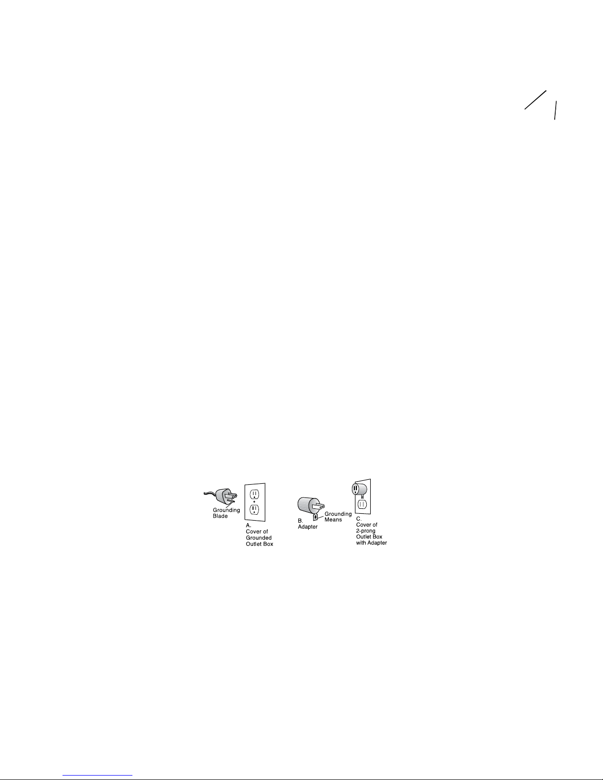
Figure 1
If your unit is for use on less than 150 volts, it
has a plug that looks like sketch A in Figure 1.
An adapter (sketches B and C) can be tempo
rarily used for connecting plugs as shown in
sketch A to 2-prong receptacles until a
qualified electrician installs an approved
3-prong receptacle. The green colored rigid
ear, lug, etc., extending from the adapter must
be connected to a permanent ground such as a
properly grounded outlet box. Some jurisdic
tions, including Canada, prohibit the use of
3 to 2 prong adapters. Where prohibited,
they should not be used.
Use proper fusing procedures.
Spare
Fuse

A-JCA-2 chuck arbor, A-WM6 wheel mandrel
and S.B0 Flexades
®
are right hand side
accessories, intended for use on the right
hand side of the lathe as you face it. Do not
use them on the left side as buff, wheel or
tool may unscrew under load. The supplied
A-TM5 tapered spindle and optional A-WM-5
wheel mandrel is intended for use on the left
side only. (Every spindle and mandrel is
marked with an R or L to indicate right or
left hand.)
Attach the spindles or mandrels by sliding
them onto the motor shaft until there is only
a 1/8″ space between the motor housing and
inside edge of the spindle or mandrel. Be
sure that the two set screws line up over the
flat on the motor shaft. Tighten both screws
securely with supplied hex key.
See Figure 2 for mounting rubber wheels or
other accessories with 1/4″ diameter center
holes on A-WM-6 wheel mandrel. Run the
lathe at slow speed without a buff (or wheel)
to see that the spindles, mandrel, or collet
holder on the lathe are running true.
Never use a buff, brush, abrasive wheel,
or any other accessory that is rated under
7,000 RPM. Never use one that appears to
wobble or vibrate. It could damage the lathe
or injure you.
Never use buffs over 4″ in diameter.
Never use grinding wheels over 2″ in
diameter. Never use rubber bonded wheels
over 3″ in diameter.
Please refer to Figure 2 for the proper mount
ing procedure for wheels or brushes on the
A-WM-6 or A-WM-5 mandrel.
Tapered Spindles: For use with 3″ or smaller
wheels with arbor holes up to 7/16″ cotton,
felt, and chamois buffs with shellac hardened
leather or lead centers. Also for felt inside
ring buffs mounted on wooden mandrels,
EXL Wheels, Radial Bristle Discs with A-4561
or A-4562 tapered spindle adapters.
Mounting Wheels onto Tapered Spindles:
Turn lathe on and run at low speed. Align arbor
hole of accessory with screw-like threads of
tapered spindle. The accessory will self tighten
as it travels up the spindle threads. To remove,
turn lathe off and manually unscrew your
wheel or buff.
Collet Holder: Loosen the two hex or allen
screws on A-CHA-5 Collet Holder and slide
onto exposed motor shaft of BL Lathe. Position
screws over the flat area of the shaft
and re-tighten.
Changing Collets and Accessories: A-CHA-5
Collet Holder comes with 3/32″, 1/8″ and 1/4″
collets for use with accessories and mandrels
with 3/32″, 1/8″
and 1/4″ diameter shanks. The
1/4″ collet typically comes installed. To switch
out a collet and/or an accessory with a differ
ent shank size, insert supplied pin with safety
spring into hole next to the two set screws.
Insert the wrench onto the flats at the tip of the
chuck nut and unscrew nut while holding pin
in place to keep spindle from turning. Remove
chuck nut and switch out collet. This may
require the use of a needle nose pliers. Replace
chuck nut and tighten after installing the
desired accessory or mandrel. Never tighten a
chuck nut without an accessory installed, as
damage to the collet may occur.
Chuck Arbor: Loosen the two hex or allen
screws on A-JCA-2 Chuck Arbor and slide onto
exposed motor shaft of BL Lathe. Position
screws over the flat area of the shaft
and re-tighten.
Changing Accessories: A-JCA-2 has a geared
3-jaw #0 chuck. Open chuck jaws as far as
necessary with key provided. Insert shank of
accessory fully into the chuck. Tighten each of
the jaws with chuck key until accessory is
secure and centered. If accessory does not
run true, reopen jaws, rotate accessory and
retighten. To release accessory, simply reopen
chuck jaws with key and pull out accessory.
The chart above shows the SFPM obtained with
different diameter wheels at various speeds.
Operation
Because of the higher maximum speed (approxi-
mately 7,000 RPM) and variable speed control,
the Foredom Bench Lathe has several advan
tages over conventional single or two speed
polishing and buffing lathes:
1. The same size buffing wheel can be used to
obtain different surface speeds, as measured
in surface feet per minute (SFPM). 3″ or 4″
diameter buffs can provide the 1,750 to 3,450
SFPM recommended for polishing and the
3,450 and higher SFPM recommended for
buffing. The chart below shows the SFPM
obtained with different diameter buffs at vari
-
ous speeds.
2. The SFPM can be varied while using the
same diameter buff or wheel. This will give
better results on different types of material.
3. The 7,000 RPM maximum speed will enable
you to get much higher SFPM with smaller 1″
or 2″ buffs or inside ring buffs, than slower
single or double speed equipment.
4. 3M Scotch-Brite™ Radial Bristle Discs in 2″
and 3″ diameters require 5,000 or higher RPM
or optimum performance, making them perfect
for use in the lathe.
5.The maximum speed of 7,000 RPM is also
fast enough to permit the use of small mount
ed abrasive points, brushes, cutters, or other
accessories in the A-CHA-5 collet holder,
S.B0-516 Flexade® or A-JCA-2 chuck holder.
For additional information on buffing and
polishing procedure, wheel selection, and
Foredom buffing and polishing compounds,
please refer to the Foredom Buffing and
Polishing Guide (Form No. 1234).
Maintenance
Lubrication: The Foredom Bench Lathe has
prelubricated ball bearings, a dust-proof motor
housing and does not require any lubrication.
The motor is designed to operate above room
temperature which will be warm to the touch but
not harmful to the motor.
Motor Brush Wear: Disconnect power cord
before checking for motor brush wear. Check for
motor brush wear periodically (about every 200
hours of continuous operation). Unscrew the
motor brush tube caps (located on front and
back of right side of lathe), check the motor
brush length, and install new brushes if the old
ones are less then 3/16″ (4.7mm) in overall
length. Be sure that the radius in the end of the
brush is in line and conforms to the commutator
surface. Replacement motor brushes (MP262 P)
are available from your dealer, the factory, or you
may order them from www.foredom.net.
Buff Speed SFPM
Diameter
1″ Full 7,000 RPM 1,750
Med 4,000 RPM 1,000
2″ Full 7,000 RPM 3,500
Med 4,000 RPM 2,000
3″ Full 7,000 RPM 5,250
Med 4,000 RPM 3,000
4″ Full 7,000 RPM 7,000
Med 4,000 RPM 4,000
Motor Shaft
set screws
Rubber
Wheel
Figure 2
Wheel Mandrel A-WM-5 and A-WM-6
Assemble all components in proper sequence.
(A-WM-5 left side wheel mandrel has same
components in opposite sequence)
 Loading...