

Page 1
®
FOREDOM
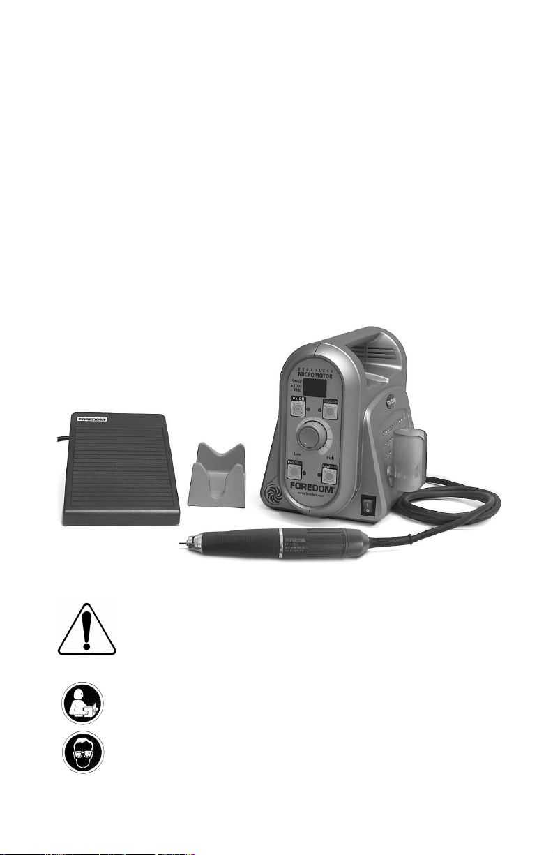
Operation and
Maintenance Manual for
K.1050 Brushless Micromotor Kit
HP4-717
HP7-7060
Foot Control
HP4-933
Cradle
Control
H.MH-150 Handpiece
For Your Safety:
Read this Manual before operating your
Foredom Micromotor Power Tool.
Always wear eye protection while operating
this Micromotor.
Page 2

Safety Instructions
A Micromotor Handpiece is a high speed rotary power tool which can be
dangerous and cause serious injury if it is not used properly.
without wearing eye protection.
• ALWAYS wear proper eye and face protection.
• ONLY use accessories rated for 50,000 rpm or higher speeds when
operating this micromotor. Follow the Allowable Rotation Speed chart
on page 9 of this manual for safe operation when using accessories with
head diameters of more than 3/32″ (2mm).
• ALWAYS observe the manufacturer's maximum speed rating when using any accessory.
NEVER use or continue to use any accessory which appears to be damaged, loose,
•
vibrating, bent, or out of balance. Inspect each accessory for cracks or flaws before use.
• ALWAYS insert the shank or arbor of an accessory or mandrel into the collet or
chuck of the handpiece as far as possible in order to provide proper support and
close the collet or chuck securely.
• NEVER use excessive side pressures which may tend to bend or break the shank or
arbor of an accessory. Let the speed of the accessory do the work.
• DO NOT stall the motor by jamming or using excessive pressure on the mounted
point, buff, wheel or accessory. This can result in damage to the motor.
NEVER operate it
WEAR a dust protector, mask or respirator to prevent the inhalation of harmful dust or
•
debris from grinding, carving or other operations performed with this power tool.
• NEVER operate with a damaged power cord. If the power cord or plug to the handpiece
is damaged, repair or replace immediately.
• USE a dust collector (vacuum system) to pull sawdust, grinding dust, or other debris
away from the work area and the micromotor intake vents.
• NEVER turn on or start the Handpiece while chuck is in open (unlocked) position.
This can damage the handpiece. Make sure that a bur is installed and secured in the
collet, that the spindle is NOT locked and that the bur can spin freely. Always operate
and store it with a bur or other accessory in the chuck and with the chuck in
the closed position.
DO NOT operate the handpiece in the presence of any flammable liquid or gas.
•
1
Page 3
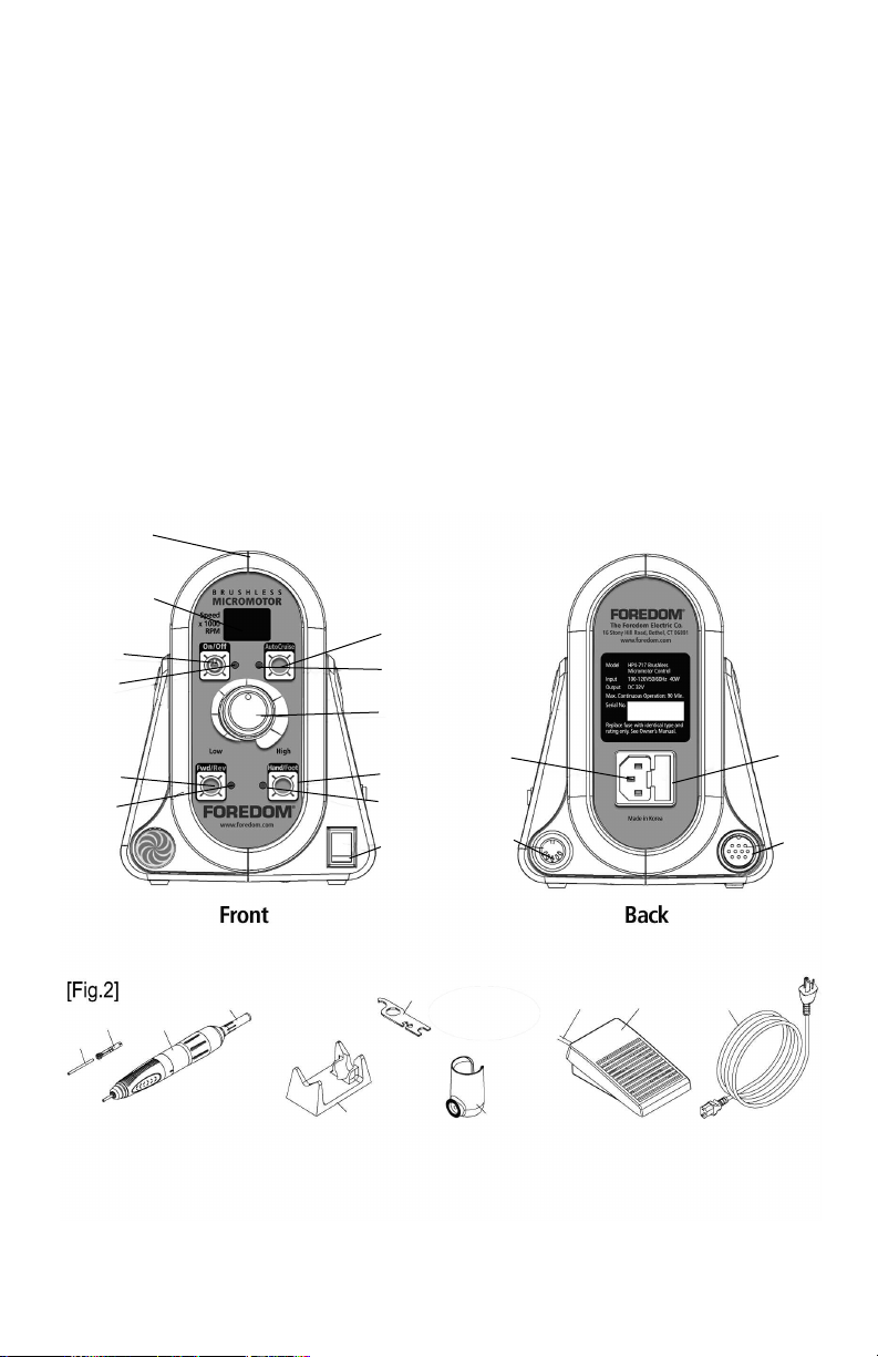
Components
1 Control Unit (HP4-717)
2 Speed Display
3 Motor On/Off Switch
4 Motor On Indicator Light
5 Auto Cruise Switch
6 Auto Cruise On Indicator Light
7 Speed Control Knob
8 Forward/Reverse Selector Switch
9 Forward/Reverse Indicator Light
1
2
3
4
10 Hand/Foot Selector Switch
11 Hand/Foot Indicator Light
12 Power On/Off Switch & Light
13 Handpiece Plug Outlet
14 Foot Pedal Plug Outlet
15 Power Cord Plug Outlet
16 Fuse Holder with spare fuse
17 Test Bur
18 3/32″ Collet (1/8″ is optional)
Collet part numbers and sizes
are listed on page 7.
5
6
7
19 Handpiece (Brushless DC
Micromotor H.MH-150)
20 Handpiece Motor Cord
21 Handpiece Cradle
(HP4-933)
22
Handpiece Holder
23
Chuck Wrench
24
Foot Pedal
25
Foot Pedal Cord
26
Power Cord
(HP7-7060)
17
18
8
9
10
11
12
20
23
15
14
25 24 26
16
13
19
21 22
2
Page 4
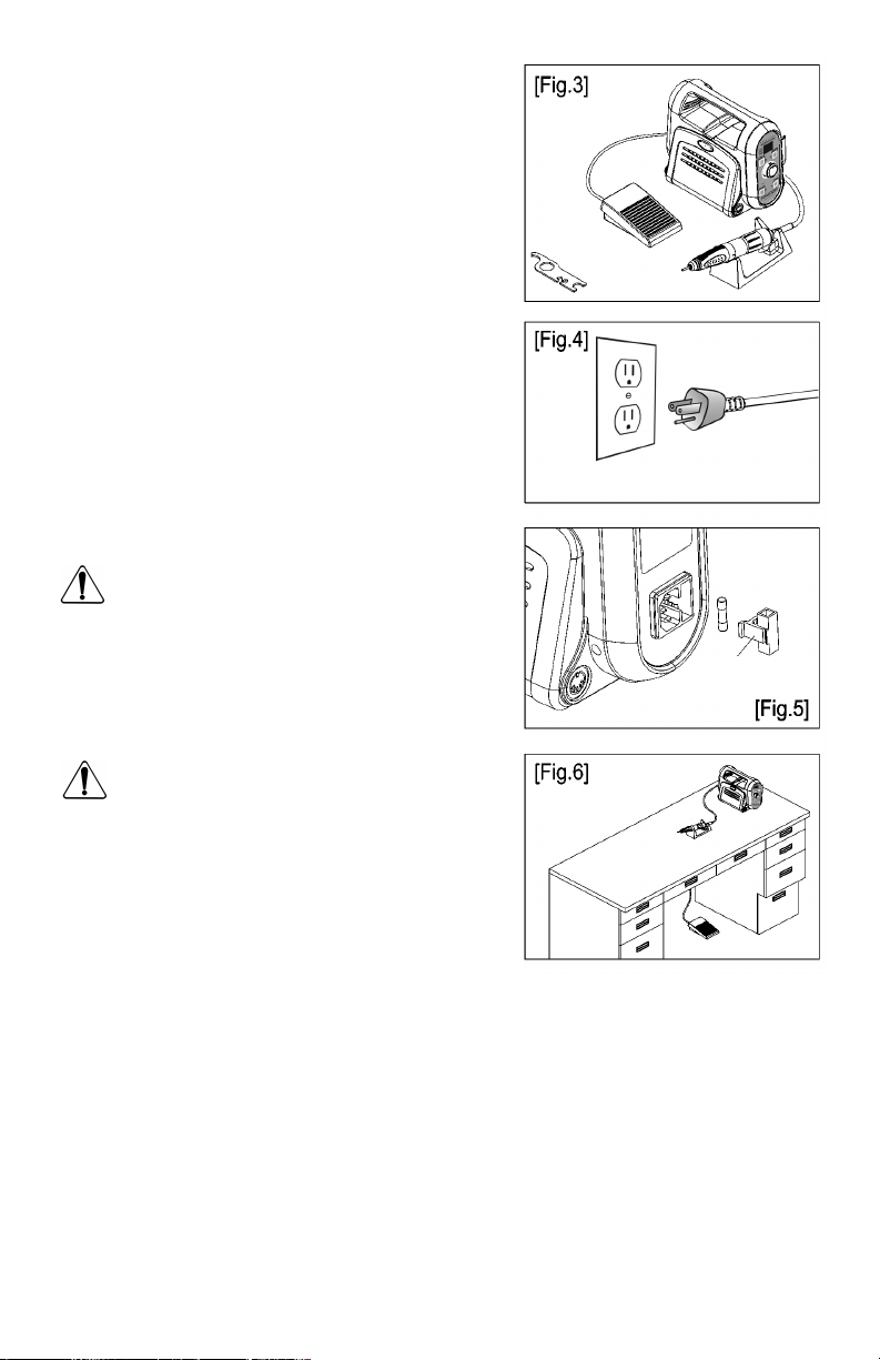
Complete Kit (Fig. 3)
Control Unit, Power Cord
Handpiece
Handpiece Holder,
Phillips Screw, Washer
Foot Pedal
Handpiece Cradle
Chuck wrench
AC Power Input (Fig. 4)
1. Check the label on the rear of the Control Unit to
make sure that the electrical specifications match
your AC power.
2. If the fuse needs to be replaced ( Fig. 6), replace it
with identical type and rating only– 5x20mm,SLOBLOW, 3.15A, 250V. For a 230V Micromotor use a
5x20mm,SLO-BLOW, 1.6A, 250V. The Fuse Holder 16
contains a spare fuse (Fig. 5).
CAUTION
• Never plug or unplug the Power Cord with wet
hands to avoid electric shock.
• Use only with a grounded AC power receptacle.
16
Installation
CAUTION
• The Control Unit should rest on a flat, steady
surface. Avoid blocking the ventilation openings in
the bottom of the case.
• Use the Control Unit in locations that have a
temperature below 100ºF. Avoid excessively dusty,
hot or humid locations.
3
Page 5
Set-up and Electric Connection
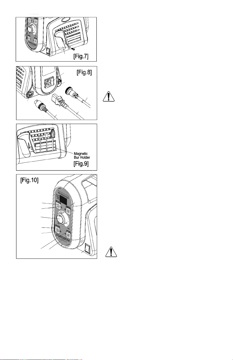
1. Fix the Handpiece Holder 22 to the right side of the
Control Unit with screw and washer. (Fig.7).
2. Plug the Handpiece Motor Cord
13 located in the rear of the Control
26 into the Power Connector 15
14
25
22
15
13
26
Motor Connector
Unit and then tighten the plug nut. (Fig.8).
3. Plug the Foot Pedal Cord
14 located in the rear of the Control Unit. (Fig.8)
4. Plug the Power Cord
in the rear of the Control Unit. (Fig.8).
20
Make sure that all cords are connected safely and
properly and that the Power Switch is off before
plugging in the Power Cord.
It is convenient to store burs on the surface of the
magnetic bur holder strips located on the side of
the controller. Some burs do not contain enough ferrous
metal to attach to the magnet. (Protect from ferrous
metal dust.) (Fig. 9).
CAUTION
Operation
a. Make sure that a bur is inserted in the motor
handpiece and collet is fully closed.
12 to off.
3
4
7
8
9
11 10
6
5
12
b. Set Power Switch
c. Plug the Power Cord
electric outlet.
d. Set the Speed Control Knob
slowest position.
e. Turn on the Power Switch
f. Select the rotation direction by pressing
Forward/Reverse Selector Switch
CAUTION Never switch rotation direction
while the handpiece is running.
Hand Mode Operation, follow steps a. through f. above, then:
1. Press the Hand/Foot Selector Switch 10 to “Hand”.
(Hand/Foot Selector indicator light
2. Press the Motor On/Off Switch
3. Set the Speed Control Knob
4. Use the Motor On/Off Switch
oot Mode Oper
F
1. Press the Hand/Foot Selector Switch 10 to “Foot”. (Hand/Foot Selector indicator light 11 lights
up orange
2. Set the Speed Control Knob
,
ation
Motor On/Off indicator light
11 lights up green.)
3 to run the motor. (Motor On/Off indicator light 4 lights up green.)
7 to desired speed.
3 to stop the motor.
above, then:
.
ough f
, follow steps a.
7 to desired maximum speed. continued
thr
4 lights up green.)
4
20 into the Handpiece
25 into the Foot Pedal Outlet
26 into a grounded
7 to the
12.
8.
Page 6

Foot Mode Operation c
3. Press the Foot Pedal 24 to run the motor from start to a maximum speed (set by the speed
control knob).
4. To increase speed, release foot pedal and allow motor to stop. Dial in new maximum speed
and proceed.
In Foot Pedal Mode the micromotor will not exceed the preset speed.
ontinued
Changing from Foot to Hand Mode
1. Press Hand/Foot selector switch, 10.
2. Press Motor On/Off switch,
3 and select a speed using the control knob 7.
Auto Cruise Mode
When the Foot Pedal is used, the Auto Cruise feature allows the speed to be maintained when the
Foot Pedal is NOT pressed. Activate by pressing the Auto Cruise Switch
Pedal depressed, for 2 seconds at the desired speed. Deactivate by pressing the Foot Pedal.
5 while keeping the Foot
Components
1 Control Unit (HP4-717)
2 Speed Display
3 Motor On/Off Switch
4 Motor On Indicator Light
5 Auto Cruise Switch
6 Auto Cruise On Indicator Light
7 Speed Control Knob
8 Forward/Reverse Selector Switch
9 Forward/Reverse Indicator Light
1
2
3
4
8
9
10 Hand/Foot Selector Switch
11 Hand/Foot Indicator Light
12 Power On/Off Switch & Light
13 Handpiece Plug Outlet
14 Foot Pedal Plug Outlet
15 Power Cord Plug Outlet
16 Fuse Holder with spare fuse
17 Test Bur
18 3/32″ Collet (1/8″ is optional)
Collet part numbers and sizes
are listed on page 7.
5
6
7
10
15
11
12
14
19 Handpiece (
micromotor H.MH-150)
Brushless DC
20 Handpiece Motor Cord
21 Handpiece Cradle
(No. HP4-933)
22
Handpiece Holder
23
Chuck Wrench
24
Foot Pedal
25
Foot Pedal Cord
26
Power Cord
(HP7-7060)
16
13
17
18
19
20
23
21 22
5
25 24 26
Page 7

CAUTION
• Do not exceed the maximum operating speed of the bur or accessory in the handpiece
to avoid personal injury.
• Before turning off the Power Switch, make sure that the motor has been stopped.
• When the unit is not in use, for maximum safety, unplug the Power Cord.
Rotation Speed Display Set Mode
NOTE: Use this set mode only when you wish to operate the micromotor handpiece with
a lower maximum RPM rating.
This function is for setting a safe maximum rotation speed of the handpiece.
a.Turn on the Power Switch 12 while pressing the Motor On/Off Switch 3 and wait for a
beep. Release the Motor On/Off Switch.
b. Set the maximum speed of the motor handpiece which you want to use by repeatedly
pressing the Hand/Foot Selector Switch 10.
c. Return to the main mode by pressing the Motor On/Off Switch.
Motor On/Off Switch Hand/Foot Selector Switch
“bc” displayed (Motor Handpiece) 25, 30, 35, 40, 45, 50 (x 1,000 rpm)
Maximum Torque Set Mode
This setting is used to match the maximum output of the control unit to the maximum
torque capability of the handpiece, or to prevent damage to the bur. The maximum
torque setting is preset at the factory to the recommended value. Use this procedure only
if you are using another motor handpiece with a lower torque rating, or if you are using
a bur which may be damaged by the full torque capability of the handpiece.
a. Turn on the Power Switch 12 while simultaneously pressing Forward/Reverse Selector
Switch 8 when you hear a beep, release the Forward/Reverse Selector Switch.
b. Set the electric current (ampere) value for maximum torque of the motor handpiece by
pressing Hand/Foot Selector Switch
displayed. The higher the current value, the more powerful the torque.
10 repeatedly until the desired amperage value is
Fwd/Rev Switch Hand/Foot Selector Switch Recommended
“c1” displayed 1a, 2a, 3a, 4a, 5a, 6a, 7a Up to 6a
CAUTION
• Do not select a current value which exceeds the rating of the motor handpiece. Too high
a rating may shorten the motor life or damage the control unit. (Consult a qualified
technician if possible.)
o check the values of maximum rotation speed and maximum torque which are
Note –
already set,
Switch
T
turn on the P
ower Switch
12 while simultaneously pressing the
5. The Set values are shown on the Speed Display LED 2 consecutively.
Auto Cruise
6
Page 8

[Fig.12]
chuck handle
23
triangular hole
bur
To order the correct Replacement
or Additional Collet check the
Handpiece Serial Number
Handpiece
Serial Nos.
808xxxx
and above
807xxxx
and below
Collet Collet
Part No. Size
HP4-117 2.35mm (3/32″)
HP4-117B
HP4-117C 3.00mm
HP7-5008
HP7-5007 3.18mm (1/8
HP7-5006
3.18mm (1/8
2.35mm (3/32
3.00mm
″)
″)
″)
Using the Motor Handpiece (MH-150)
Changing Accessories
Burs and other accessories can be inserted or
removed from the handpiece collet when the collet
is open. To open the collet:
1. Turn off the motor using the Motor On/Off
3 and the Power Switch 12.
Switch
2. Twist the Chuck Handle in the “R” or release
direction (clockwise) until the raised indicator bar
clicks into the far left mark ( 8>) on the silver
center ring (Fig.11).
2. Remove the accessory and replace with another
accessory. Insert the ‘new’ accessory shank fully
1
(about 1
You should feel it touch the back of the collet.
4.Twist the knurled Chuck Handle toward the “S”
or secure position by turning counter-clockwise
until it snaps to lock the collet. The accessory and
the collet will be able to spin freely.The raised
collet indicator bar will be above the far right
(
Note: The intermediate position between “S” and
“R” holds both the spindle and the accessory in a
locked position. This is useful to unscrew an
over-tightened mandrel screw.
Never turn the power on when the collet
is open or in the intermediate position.
The spindle is in the locked position and
will not turn.
motor.
How to Remove and Install the Collet
1. With knurled Chuck Handle in “R” release position
and bur or accessory in collet, place triangular hole
in Chuck Wrench
head and unscrew the collet counter-clockwise (Fig.
12) Remove collet.
2. With bur or accessory in new collet, thread into
handpiece. Place triangular hole in Chuck Wrench
over triangular flats of Collet head and tighten the
collet clockwise. Be careful not to over-tighten. Test
to insure that new collet releases accessory smoothly
in the “R” released position. Test to insure that new
collet holds firmly in the “S” secure position and
spindle rotates freely.
7
⁄8″) into the collet for maximum support.
<
8) mark in the silver center ring.
This will damage the
23 over triangular flats of Collet
23
Page 9
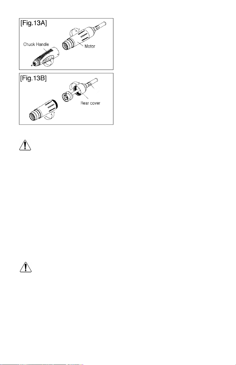
Disassembling the Chuck Handle
and the Motor
The Chuck Handle and the Motor are disassembled by continuously turning the Chuck Handle
counterclockwise (Fig.13A).
Detaching the Motor
and the Motor Cord
Unplug Handpiece Motor Cord Assembly 20
20
from Handpiece Plug Outlet 13 on the back of
the control. The Motor Cord Assembly
20 can be
replaced by unthreading the Rear Cover from the
Motor Housing (Fig.13B).
CAUTION
It is recommended that a bur be kept in the chuck at all times. Do not operate the
handpiece without a bur in the chuck.
• Use only recommended burs.
• Always be sure chuck is free of dirt or debris before replacing a bur.
• After replacing a bur, make sure that the Collet Chuck is fully closed before running the Motor.
• DO NOT to open the collet while the motor is running. It will damage the handpiece.
• Always put the Handpiece on the Handpiece Cradle 21 or in Handpiece Holder 22 while not in
use. (Fig.7). Take special care not to drop it on the floor.
• Thoroughly clean the Collet before reassembling. Clean at least once a week for
longer life.
• Keep the Handpiece clean and free of dirt and debris during disassembly.
• The spindle and the motor should be disassembled only by a qualified repair facility.
CAUTION
• Never exceed the maximum rotation speed specified by the manufacturer or for the bur
being used.
• Large burs, even when operated below maximum rated speed, may begin to vibrate. Speed
should be reduced immediately to prevent damage to the bur
until it touches the back of the Collet Chuck.
,
• Be sure to insert the Bur shank all the w
ay
handpiece
,
, or operator.
T
tighten the Collet Chuck. If the Bur is used while not inserted completely, it is very dangerous
because vibration may cause it to come out, bend, or break.
8
hen
Page 10
Error codes
Error
Code Status Cause
1. One or more hall sensors defective
“1E” Motor sensor error 2. The Motor Cord is unplugged or defective.
3. The Motor Cord is broken.
1. The Collet Chuck is opened.
“2E” Motor lock error 2. The Motor Handpiece is mechanically defective.
3. The Motor Handpiece is electrically defective.
“4E” Motor overvoltage 1. The circuit of the Control Unit is defective.
detection error
1. The Control Unit has been operated under a high load condition
for too long a time.
“5E” Overheat error 2. The Control Unit has been exposed to an excessively
warm environment (more than 100
3. Air openings are blocked.
4. Temperature sensor is defective.
“6E” Overload error 1. The motor Handpiece was operated under an overload condition,
or was stalled by jamming the bur into the work.
“7E” Control Circuit 1. The circuit of the Control Unit is defective.
Board error
ºF.)
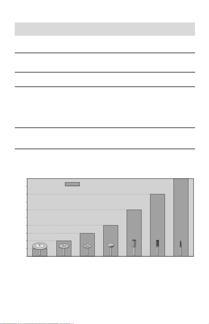
50,000
45,000
40,000
35,000
30,000
25,000
20,000
15,000
10,000
5,000
0
Accessory more than 1
1
⁄2″ 1″ 3/4″ 1/4″ 1/8″ 3/32″ less than 3/32″
Rotation Speed – RPMs
Diameter (40mm) (28– 40mm) (18 –28mm) (8–18mm) (4 –8mm) (2 – 4mm) (less than 2mm)
Allowable Rotation Speed
he chart is a general guide for the maximum rotation speed of conventional burs. The allowable
T
rotation speed can be slightly different,
depending on bur materials or types
.
9
Page 11

Troubleshooting
NOTE: When an error reading is displayed, turn off the power switch for a few seconds and then turn it on again. If
“
5E” is displayed wait for about ten minutes. If the error reading re-appears, follow the Troubleshooting Chart below.
Trouble Check Points Corrective Actions
Power
Lamp
Does Not
Light
d
displayed
displayed
displayed
Motor
Does
Not
Run
displayed
displayed
Foot Pedal
Does Not
Work
Handpiece overheats or is noisy
while operating
at no load
Motor
Vibrates
Excessively
and is
Unusually
Noisy
Make sure that the Power Cord is correctly Correctly plug in the Power Cord.
plugged into the outlet and the control unit.
Check if the fuse is blown. Replace only with the recommended fuse. If
Make sure Power Switch is working properly. Replace the Power Switch.
“1E”
Make sure Motor Cord is plugged in properly. Correctly plug in the Motor Cord. If error code
isplayed
“2E”
Check if the Collet Chuck is open. If open, close the Collet Chuck. If error code
“4E”
The circuit of the Control Unit is defective. Repair or replace.
Check if the Control Unit has been used at a Turn off the Power Switch for about 10 mins.,
high load and for a long time. then restart the Control Unit. If error code
“5E”
Check for high workplace temperature. If too warm, move the Control Unit to a loca-
Check control air openings for blockage. Unblock air opening.
Temperature sensor is defective. Replace the sensor.
Check if the Control Unit has been excessively Press the Auto Cruise Switch or turn off, then
used under a high load condition. press the Motor On/Off Switch. If error code
“6E”
Check if the Collet Chuck is open. If open, close it by turning the Chuck Handle.
Make sure the shaft of the Motor Handpiece If it cannot be rotated with the chuck closed,
can rotate freely. the spindle of the Motor Handpiece is defec-
“7E”
The circuit of the Control Unit is defective. Turn off the Power Switch for about 10 mins.,
Check if Foot Pedal Cord is properly plugged in. Plug in the Foot Pedal Cord correctly.
The Hand/Foot Selector Switch is set to “Hand”. Set the Hand/Foot Selector Switch to “Foot”.
Foot Pedal still does not work. Repair or replace it.
The ball bearings are defective. Repair the Motor Handpiece.
Make sure that the Collet Chuck is free of dirt. Thoroughly clean the Collet Chuck.
The rotation speed is too high. Reduce the rotation speed. Refer to
Check if the bur shaft is bent,
of round or unbalanced.
Make sure that the ball bearings are in Repair or replace the Motor Handpiece.
good condition.
or bur is out
the fuse blows again, repair or replace the unit.
continues, replace the Motor Cord.
continues, repair or replace the handpiece.
continues repair or replace the control unit.
tion with an indoor temperature of 32~100ºF.
continues, repair or replace Control Unit.
tive. Repair or replace it.
then restart the Control Unit. If error code
continues repair or replace the control unit.
Allowable Rotation Speed chart.
Replace with a new bur
.
Caution:
s should be performed only by qualified per
Repair
10
sonnel.
Page 12

Repair Services
Authorized repair service is available at the Foredom factory in Bethel, CT. Send items for repair to
the factory marked “Attention: Repair Department”. Enclose the item(s), a packing list, daytime
phone number, return address, and information regarding the problem or repairs required.
Estimates of repair cost will be made upon request. It is our policy not to proceed with a repair
without your approval if the cost (labor plus parts) is more than fifty percent of the cost for a new
replacement. You will be notified by mail and advised of the cost to repair and to purchase a new
replacement. Please allow three business days for an estimate to be done and five to seven business days for repair work to be completed after we receive your approval to proceed.
Please retain your proof of purchase for warranty repairs.
Warranty
Foredom warrants its product to be free of defects in material or workmanship for a period of
two years after purchase.
During the warranty period, the defective product will be repaired or replaced without charge
or, at our option, the purchase price will be refunded.This warranty does not cover damage
caused in transit or by accident, misuse, or ordinary wear.
ALL IMPLIED WARRANTIES, INCLUDING BUT NOT LIMITED TO WARRANTIES OF FITNESS AND
MERCHANTABILITY, ARE HEREBY LIMITED IN DURATION TO A PERIOD ENDING ONE YEAR
FROM DATE OF PURCHASE,AND WE WILL NOT BE LIABLE OR RESPONSIBLE FOR ANY SPECIAL
OR CONSEQUENTIAL DAMAGES.
Repair or replacement will be made at our option if the product is returned postpaid to:
The Foredom Electric Company, 16 Stony Hill Road, Bethel, CT 06801
All warranty repairs must be done at the factory at the address above.We will not pay any
shipping or transportation charges.
This warranty only covers the original purchaser of the product. Proof of purchase may
be requested.
Some states do not allow limitations on how long an implied warranty lasts, so the above
limitation may not apply to you. This warranty gives you specific legal rights, and you may also
have other rights which vary from state to state.
For More Information
For more information on Foredom machines, handpieces or accessories, contact your local dealer.
When no local dealer is available, write, call or fax:
The Foredom Electric Company, 16 Stony Hill Road, Bethel, CT 06801
(203)792-8622, Fax: 203-796-7861 or Email: [email protected]
Visit our website: www.foredom.com
F-1228 n 1/09
Printed in U.S.A.
 Loading...