

Page 1
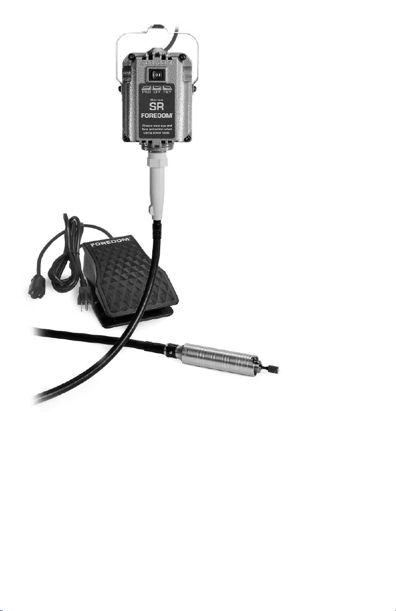
Owner’s Manual
for 1/6 HP
Series SR
Flexible Shaft
Power Tools
See Insert with
Special Instructions
for Heavy Duty
Series SRH Models
For Your Own Safety
• Please read this Assembly, Operation, and Service Manual
before operating your Foredom power tool.
• Always wear eye protection while using power tools.
• Only use accessories rated for use at 18,000 RPM.
®
FOREDOM
www.foredom.net
Form 1268 n 1/12 Printed in U.S.A.
Page 2

Contents
Page
Safety Instructions 2–4
Series SR Motors and Speed Controls 4-7
Assembly Instructions 5–6
Assembly and Adjustment of Shaft, Sheath & Handpiece 5
Connecting Foot Controls 6
Connecting Table-Top Dial Speed Controls 6
Operation – General Guidelines 7
Foredom Handpieces and Rotary Accessories 8–10
Attaching Accessories to Handpieces 9
Handpiece Lubrication 10
General Accessory Recommendations 11–12
Maintenance Procedures 13–14
Routine Motor Cleaning and Lubrication 13
Replacement of Worn Shafts and Sheaths 14
Replacement of Motor Brushes 14
Repair Service 15
Recommended Spare Parts and Supplies 15
Motor Hangers 15
Limited Warranty 16
Contact Information 16
Safety Instructions
Before using your Foredom power tool,
please read safety instructions.
They are
for your protection and should always be
followed to reduce the risk of personal
injury or damage to the tool.
• Always wear proper eye and face protection.
Wear safety glasses or face shields whenever you operate a Foredom or any power
tool to prevent serious eye or face injuries.
• Secure the work piece or item that you are
working on
in a vise or other work holding
device. Holding it with your hand can result
in serious hand injury.
• Always use a proper dust collection system or
wear a respirator
to prevent
the inhalation of
dust particles, polishing compounds, or
other debris into the lungs.
• Do not wear loose fitting clothing or jewelry.
Loose clothing or jewelr
y can become
entangled in the rotating accessory. Do not
wear items such as neckties, necklaces, or
bracelets when operating power tools. Be
tie back or secure long hair.
sure to
•
Secure power tool to motor hanger or work
surface.
Flexible shaft power tools can
“jump” at start up or vibrate during operation. The tool should be properly secured in
order to prevent it from vibrating off of the
motor hanger or work bench.
•
Never operate any accessory at speeds above
its maximum rated speed.
used, all of Foredom's accessories can be
operated at the speed ratings listed in the
Foredom Accessory Catalog or specified on
kits and packages.
manufacturer's speed rating before using
accessories other than those from Foredom.
• For added safety and comfort while using
this power tool for carving or other applications, it is recommended that you wear a
2
How-To Videos on
www.foredom.net
Click on our homepage link
where Foredom’s National
Sales Manager shows you
the basics of using and
maintaining flexible shaft
machines.
Click to View:
1. Intro & Proper Set-up
2. Safety Guidelines
3. Handpieces &
Accessories
4. Shaft and Sheath
Maintenance – Grease
and Replace
5. Motor Maintenance–
Remove Dust, Replace
Motor Brushes
We have other productrelated videos embedded
throughout our website.
We suggest that you take
the time to watch these
since they help to clarify
product features,
differences, and uses.
Visit Foredom on
www.youtube.com
When properly
Always
find out the
Page 3

heavy canvas or leather apron. It will protect
you from dust, debris and chips as well as
help prevent injury if the handpiece slips off
the workpiece. It will also help prevent loose
clothing from getting caught in a rotating
cutter, bur or other accessory.
• Never use or continue to use any
accessory which appears to be damaged,
loose, vibrating, or out of balance.
Inspect
each accessory for cracks or flaws before
using it. Avoid knots, imperfections in the
wood or metal objects like nails, which
could damage or catch the accessory.
• Always insert the shank or arbor of an
accessory or mandrel into the collet or
chuck of the handpiece as far as possible in
order to provide proper support and tighten
the collet or chuck securely.
• Never use excessive side pressure which
may bend or break the shank or arbor of an
accessory. Let the speed of the accessory
do the work.
• Do not stall the motor by jamming or using
excessive pressure on the accessory. This
can result in damage to the motor or
flexible shaft.
• Never operate the motor with the outer
sheath removed from the flexible shaft.
• Always disconnect the power cord before
servicing the motor or removing the flexible
shaft or sheath.
• Never operate your power tool during a
perceptible power decrease. Turn power tool
off and do not use until power is
fully restored.
• Use proper grounding procedures. This tool
should be grounded while in use to protect the
operator from electric shock. The tool is
equipped with an approved 3-conductor cord
and a 3-prong grounding type plug to fit the
proper grounding receptacle. The green (or
green and yellow) conductor in the cord is the
grounding wire. Never connect the green (or
green and yellow) wire to a live terminal. If
your unit is for use on less than 150 volts, it
has a plug that looks like sketch A below.
An adapter (sketches B and C) can be used for
connecting plugs as shown in sketch A to
2-prong receptacles. The green colored rigid
ear, lug, etc., extending from the adapter must
be connected to a permanent ground such as
a properly grounded outlet box.
Some jurisdictions, including Canada, prohibit the use
of 3 to 2 prong adapters. Where prohibited,
they should not be used.
Use only 3-wire
extension cords that have 3-prong grounding
type plugs and 3-pole type plugs and 3-pole
receptacles that accept the tool’s plug. Always
disconnect the power cord before servicing
the tool. Never use in an area where
flammable vapors are present.
N
ever change motor direction while the motor is running.
Changing direction while motor is running can damage the motor or
flexible shaft or lead to premature wear. To turn motor off, remove foot
from foot pedal speed control, or turn dial speed control to
“off”
position, and set rocker switch to “off” (center) position on motor.
3
Page 4

N
ever change motor direction
while the motor is running.
OFF– no rotation.
FORWARD – counterclockwise shaft rotation.
Forward is going to be the most commonly
used setting. Right-handed people will get the
most control in the forward direction.
Forward Motor Rotation
• ONLY use Chisel or Hammer handpieces or
Angle Grinder attachment for H.30
piece in
Forward Rotation. Using Chisel or
Hammer handpieces or Angle Grinder
attachment in reverse can damage the handpiece, attachment, flexible shaft, or motor
and may cause injury.
• Use the forward motor direction ONLY for
fluted burs, drills and cutters.
efficiently
• Many mandrels have right-hand threaded
only when turning in this direction.
arbor screws which will unscrew in the
reverse direction.
• Dust and debris flies away from the user
when operated in
forward in the left hand.
®
hand-
Most will cut
REVERSE – clockwise shaft rotation.
Advantages of Reverse Rotation
• Left-handed users will have better control in
the reverse direction.
• For right handed use, dust and debris flies
reverse.
away in
• Alternating motor direction helps to extend
the life of mounted abrasive points, buffs,
brushes, sanding bands, and Typhoon
• Reverse helps with accomplishing symmetri-
cal grinding and carving techniques.
• Reverse is good for “backing out” stuck drill
bits and extending the life of sanding bands
and abrasive accessories.
• Alternating motor direction makes it easier
and faster to polish metals.
• Be sure to use a mandrel with a left-hand
threaded arbor screw.
®
burs.
• Whether you are right or left handed or
operate in forward or reverse,
precautions
taken against dust and debris are always
necessary and important.
• Always securely tighten chuck nut or chuck
jaws of handpiece with wrench or chuck
key so that it will not come loose in the
• Be sure to insert the shank of the
accessory as far as possible into the collet
or chuck to give it maximum support.
•
Always wear proper eye and face protection.
Wear safety glasses or face shields whenever you operate a Foredom or any power
tool to prevent serious eye or face injuries.
reverse or forward operating directions.
Foredom®1/6 HP Series SR Power Tools
You have purchased a fine quality power tool which will perform a wide variety of tasks
difficult to do with any other kind of power tool. Foredom power tools are manufactured to
high standards of precision and performance and with proper use and regular maintenance
will give you years of trouble-free performance. This manual contains instructions for the
assembly, operation, and servicing of Foredom’s 1/6 hp Series SR motors.
M.SR Hang-Up Style
M.SRB Bench Style M.SRM Bench Style
4
with built-in control
Page 5
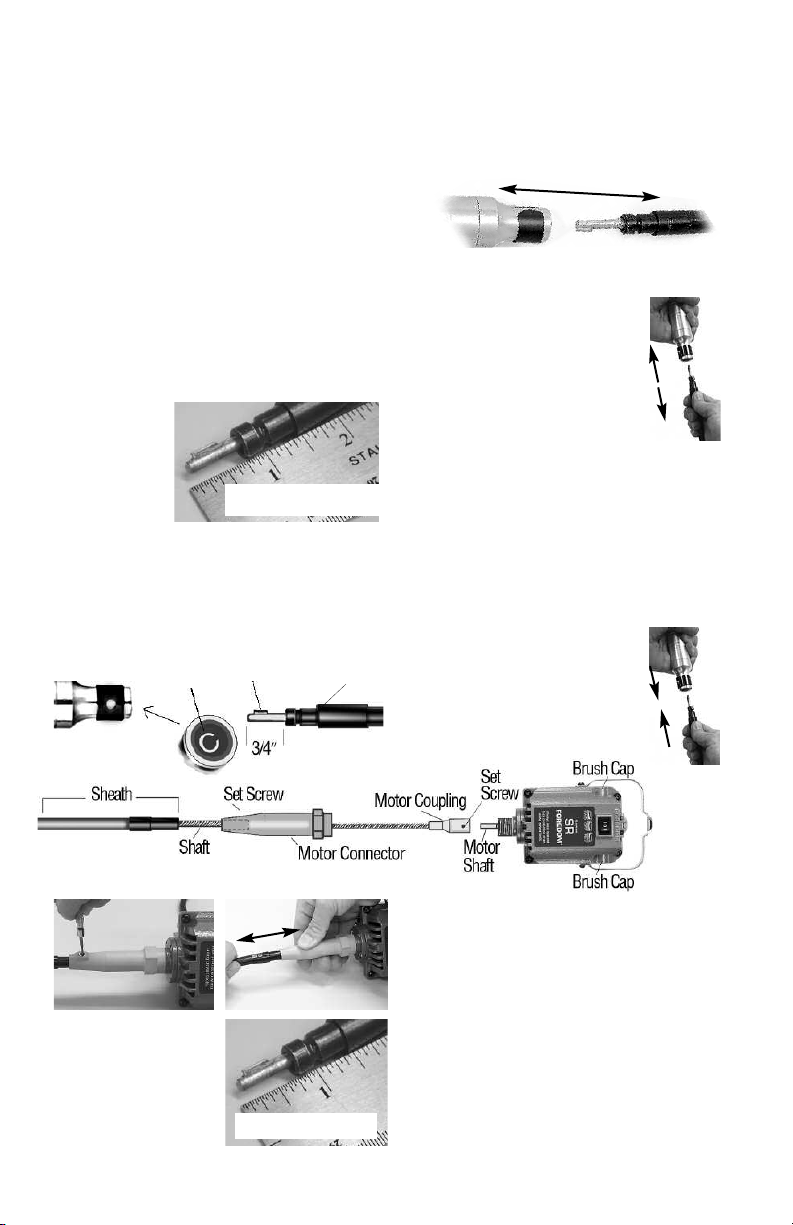
Your Series SR flexible shaft power tool consists of a motor, flexible shaft and sheath, speed control
(foot or manual) and a handpiece. Locate and identify all components, parts and accessories you
purchased before discarding the packing list and packing materials that came with your power tool.
Assembly Instructions
Always make sure your power tool is
unplugged during assembly!
After identifying all the components of your
power tool, assemble it in the following manner:
Assembly and Adjustment of Flexible
Inner Shaft, Outer Sheath, & Handpiece
Proper assembly and adjustment of the
flexible shaft and sheath are critical for the
correct operation of your Foredom power tool.
The exposed tip
(handpiece end)
of the flexible
shaft (with handpiece removed)
must extend 3/4
(19mm) beyond the sheath.
″
Important Note: The shaft and sheath
should be checked and adjusted (if necessary) even if you received them assembled
and attached to the motor!
keyway
slot
inside,
back end of
handpiece
IMPORTANT!
key tip end of shaft
metal
sheath
tip
Please follow these directions to assemble
and adjust the shaft and sheath.
To check the shaft and sheath you must first
remove the handpiece.
The handpiece is easy to remove
from the flexible shaft.
To remove:
1. First make sure your power tool
is unplugged.
handpiece off the shaft and sheath
with a firm grip.
holding the black colored metal outer sheath tip facing upward, turn on the motor so that it is running
at about half speed
inner key tip is still rotating, grip the handpiece and
push it onto the sheath tip with one firm motion
until it snaps into place (shown below). This
procedure will align the key tip into the keyway slot
(as shown below at left). To verify
this, insert and tighten an accessory
into collet or chuck, turn on control
to low speed and observe that the
accessory rotates smoothly.
Simply pull the
To Re-attach Handpiece: while
and then turn it off. While the
IMPORTANT!
2. With the handpiece removed, place the entire
unit on a flat surface with the shaft and sheath
extended straight. Loosen the set screw on the
motor connector.
piece end) of the flexible shaft so that it extends
″ (19mm) beyond the sheath, as shown at
3/4
left. This is done by moving the sheath in or out
of the motor connector (motor end) as shown
at left.
3. When the correct adjustment is made,
re-tighten the set screw in the motor connector
and re-attach handpiece onto the flexible shaft.
5
Adjust the exposed tip (hand-
Page 6
Be sure to follow the grounding
instructions on page 3 of this manual
while attaching the speed control to a
power outlet.
Wait for motor to stop rotating
before switching between forward
or reverse.
To turn motor off, remove foot from foot pedal
speed control, or turn dial speed control to “off”
position, and set rocker switch to “off” (center)
position on motor.
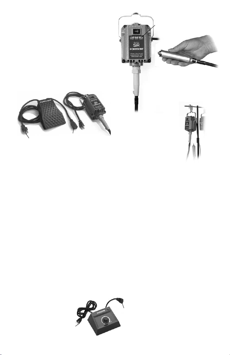
3-prong plug
connects to
power outlet
Connecting the Foot Speed Control
The electrical specifications for your power tool are
listed on the label on back of motor. It shows proper
voltage and currents to use with your power tool.
A 115 Volt, 50/60 cycle (Hz) motor can be used with
the models C.FCT-1 and C.SCT-1 foot controls on 115
Volt
AC current only. The 230 Volt, 50/60 cycle (Hz)
motor can be used with the models C.FCH-2 and
C.SCH-2 foot controls on 230 Volt
To connect the foot control to the motor, insert the
3-prong plug on the end of the motor power cord into
the socket connector on the shorter power cord on
the foot control.
the “off” position,
longer power cord from the foot control into a proper
3-prong power outlet.
When your foot is not pressing the foot
control, the motor should not be running.
Your foot must maintain steady contact with the pedal
during operation. Holding the handpiece in your hand,
put the motor fwd/off/rev switch in the desired “on”
position, begin with a light touch, start out slowly
and gradually increase the
speed. Finding the right speed
for any specific task is a
matter of experimentation
and experience.
socket
connector for
motor plug
AC current only.
With the motor fwd/off/rev switch in
plug the 3-prong plug on the
3-prong plug connects
to power outlet
orward/ Off/Reverse
F
Rocker Switch on motor
Hold the handpiece
securely before selecting
the rotation direction and
turning the motor to the
desired “on” position.
Hanging Motor Installation
M.SR Motors should be hung up
about 30″–40″ above the work
surface and to the right of the
work if you are right handed or to
the left of the work if you are
left handed.
Use a safety clip or hook like the
one shown to prevent the motor from jumping or
twisting off an open hook at start up or during use.
Properly securing the motor will help to prevent
injury to the user.
All Foredom motor hangers have this type of safety
clip (see page 15). If an “open hook” is used be sure
to secure the motor to it with wire or heavy tape.
Connecting the
Table-Top Dial Speed Control
The motors can also be used with the C.EM-1 (115
volt) or C.EMH-2 (230 Volt) dial speed control on AC
current. Connect the control to the motor by inserting
the 3-prong plug on the end of the motor power cord
into the socket connector on the shorter power cord
on the dial control. With motor fwd/off/rev switch in
the “off” position and the dial indicator arrow also
in the “off” position on the control, plug the
3-prong plug on the longer power cord from
the dial control into a proper 3-wire outlet (see page
3). Holding the handpiece in your hand, put the
motor fwd/off/rev switch in the desired “on”
position, begin with a light touch, start out
slowly and gradually increase the speed.
Finding the right speed for any specific
task is a matter of experimentation
and experience.
6
socket
connector
for motor
plug
Page 7
Operation –
General Guidelines
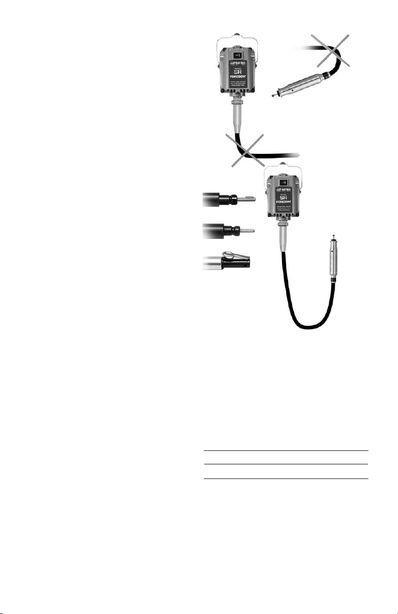
Do Not
Do This!
Read all the safety instructions in this
manual before operating your Foredom
®
Power Tool. Proper eye and face protection
must be worn to protect you from injuries
caused by flying debris, chips, or sparks
which might result from the work
being done.
It is possible to use rotary or chisel
handpieces not made by Foredom with
your Foredom flexible shaft power tool.
However, this is not recommended since
their function and safety cannot be
assured by Foredom.
Your Foredom motor may be operated in a
vertical or horizontal position, but it should
be enclosed or confined so as to restrict air
circulation. If the motor is hung up above a
workbench, be sure it is fastened securely to
the wall or motor hanger. The motor may develop a high operating temperature (up to 100
ambient) after prolonged use, and it will be too
hot to hold. This will not harm the motor which
is designed to operate at this temperature for
prolonged periods.
not
o
F +
Do not force the tool
Let the speed of the tool do the work. Avoid
using too much pressure. Generally, slower
speeds are used for rougher, heavier work or
when greater control over the accessory is
required for precise, delicate work. Higher
speeds are used for buffing, cutting and
polishing. Read Accessory Recommendations
on pages 11 and 12 of this manual.
Voltage Decreases
Never operate a power tool during a perceptible
power decrease. Turn off tool and unplug until
full power is restored.
Always wear proper eye and face
protection when operating a Foredom
power tool.
Wait for motor to stop rotating before
switching between forward or reverse.
o turn motor off, remove foot from foot pedal
T
speed control, or turn dial speed control to “off”
position, and set rocker switch to “off” (center)
position on motor
.
Do Not
Do This!
Shaft Tips
Key Tip
Square Drive
Slip Joint
Minimum
Operating
Radius
Do not bend shaft and sheath
at tight angle
When operating your Foredom tool be careful not
to bend the flexible shaft too much at either the
handpiece or motor shaft connections.
sheaths last longer when they are used without
sharp bends. If used at angles or loops, wear will
occur at the points of greatest friction. Excessive
heat and wear will occur if the bend is too great.
Torsional Breaking Point:
Key Tip (Standard) Shaft 24-lbs.-in.
Square Drive (Heavy Duty) Shaft 50-lbs.-in.
Slip Joint (European) Shaft 24-lbs.-in.
Follow these guidelines for trouble-free use:
a 4″ or larger radius,
maintained for shafts on all motors. There is no
way to avoid ultimate wear and under normal
conditions a flexible shaft machine may require
several replacement shafts and sheaths during its
lifetime. (Follow shaft and sheath assembly
instruction in the Assembly section of
this manual.)
as shown, should be
7
Shafts and
Page 8
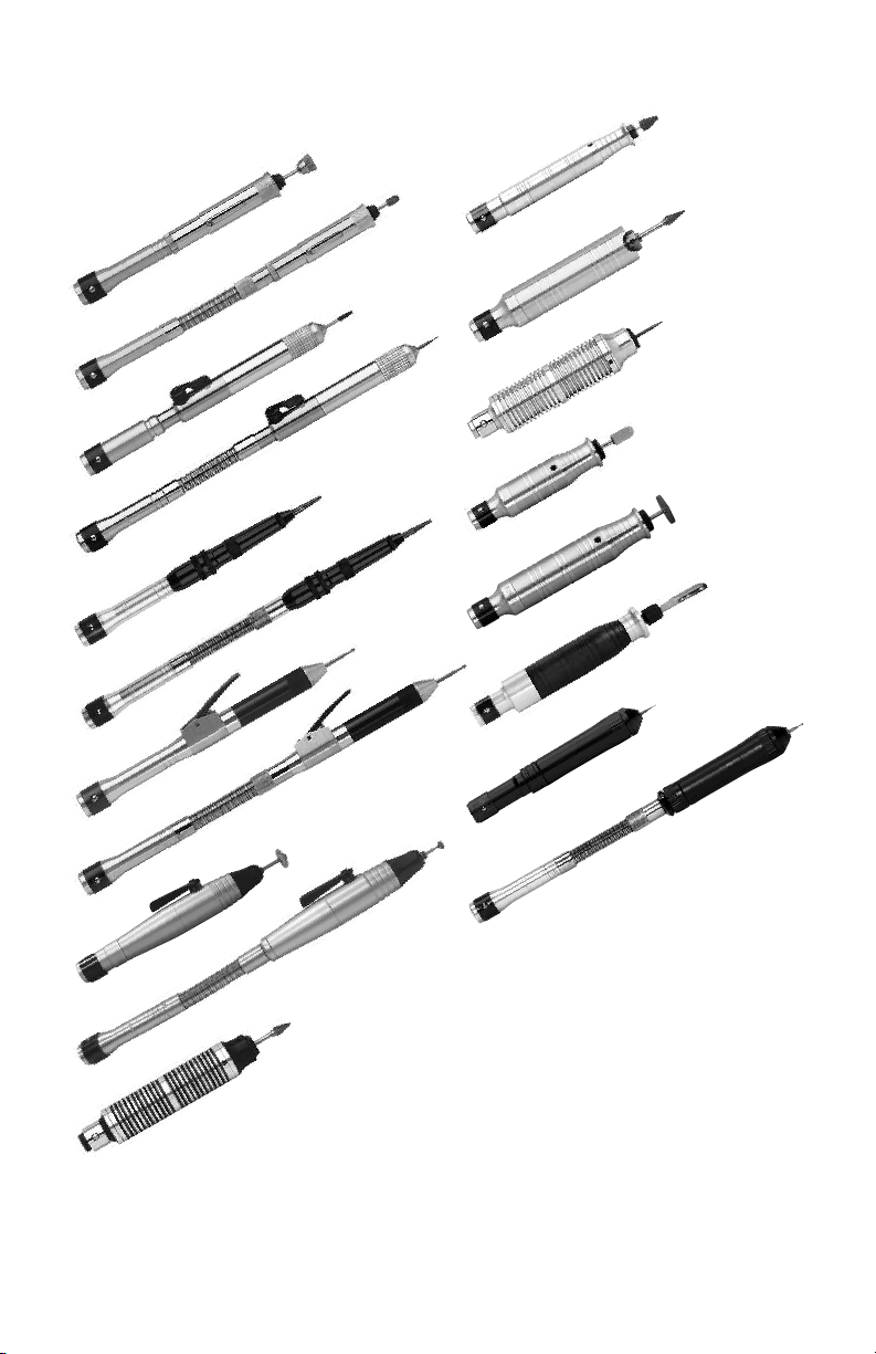
FOREDOM®Handpieces (burs not included)
H.28
H.8
H.8D
H.10
H.10D
H.15
H.15D
H.18
H.18D
H.30
H.35
H.43T
H.44T
H.50
H.52
H.52D
With the H.35
handpiece use only
®
accessories rated
for 35,000 RPM
or higher.
H.20
H.20D
H.25
Never run Handpieces H.15, H.15D or
H.50 in reverse rotation.
See insert for special square
drive handpieces for use with
Series SRH motors.
8
Page 9

Attaching Accessories to Handpieces
Directions for attaching accessories to handpieces
vary according to the type of handpiece being used.
Locate the model number of your Foredom
handpiece from the photos on page 8.
Always wait
for the motor, flexible shaft and accessory to come to a
complete stop before changing an accessory.
(Handpieces listed in brackets are for use with
Series SRH models only.) Attach the accessory
according to the following:
Collet Types –
8, 8D, 25, (25H),
28, 28SJ,
35SJ, 43T, 44T, 44TSJ, &
(28H),
35,
(44HT) Handpieces:
A collet is an interchangeable slotted cylinder
inserted tightly into the interior of a handpiece to
hold a bur or other rotary accessory. The diameter
size of the collet must match the diameter of the
accessory’s shank.
General Directions: Be sure to use the correct
shank size. The correct shank will fit snugly inside
the collet.
Caution: Never tighten a collet unless
an accessory has been inserted. Tightening an
empty collet or inserting an accessory which is too
small or too large may damage the collet.
8, 8D, and 8SJ Handpieces:
To change a collet: slide back the chuck guard and
use one wrench to hold the spindle and the other to
unscrew the chuck nut by turning counterclockwise. Remove chuck nut to expose collet and pull
collet out of handpiece shaft. Slip new collet in
place and tighten chuck nut with wrenches.
To insert accessory: insert shank as far as possible
into the collet. Tighten chuck nut. T
est for a secure
hold by pulling on accessory. Remove wrenches.
To release an accessory, follow the same steps.
Accessories can be released when chuck nut is
loosened. If accessory does not run true, loosen
chuck nut, rotate accessory, and retighten.
25, (25H), 28, 28SJ, (28H), 35,
35SJ, 43T, 44T, 44TSJ & (44HT) Handpieces:
To change a collet
: 1. Insert pin provided into the
pilot hole and through the spindle hole (turn spindle to align holes). Apply wrench and unscrew
chuck nut by turning counterclockwise.
2. Remove chuck nut to expose collet.
3. Pull collet out of
handpiece spindle.
4. Slip new collet in place
and screw on chuck nut.
5. Remove pin.
Pilot or
Spindle
Hole
25, (25H), 28, 28SJ, (28H),35, 35SJ,
43T, 44T, (44HT), and 44TSJ Collet Handpieces:
To insert or change accessories:
provided into the pilot hole and through the
spindle hole (turn spindle to align holes). Loosen
chuck nut slightly with wrench provided. Insert
shank of accessory into collet. Tighten chuck nut
with wrench, keeping pin in pilot hole. Test for a
secure hold by pulling on accessory.
Chuck Type – 30
and (30H) Handpieces:
These handpieces have a
geared 3-jaw #0 chuck. Open
chuck jaws as far as necessary with key provided. Insert shank of accessory
fully into the chuck. Tighten jaws with chuck key
until accessory is secure and centered. If accessory
does not run true, reopen jaws, rotate accessory
and retighten. To release accessory, simply reopen
chuck jaws with key and pull out accessory.
Hammer Type – 15, 15D, & 15SJ Handpieces:
These handpieces have a threaded spindle. Thread
anvil or stylus into threaded spindle as far as it will
go with clockwise motion. Insert pin provided into
cross hole in anvil or stylus. Tighten and remove
pin. To release accessory, insert pin into the cross
hole and unthread.
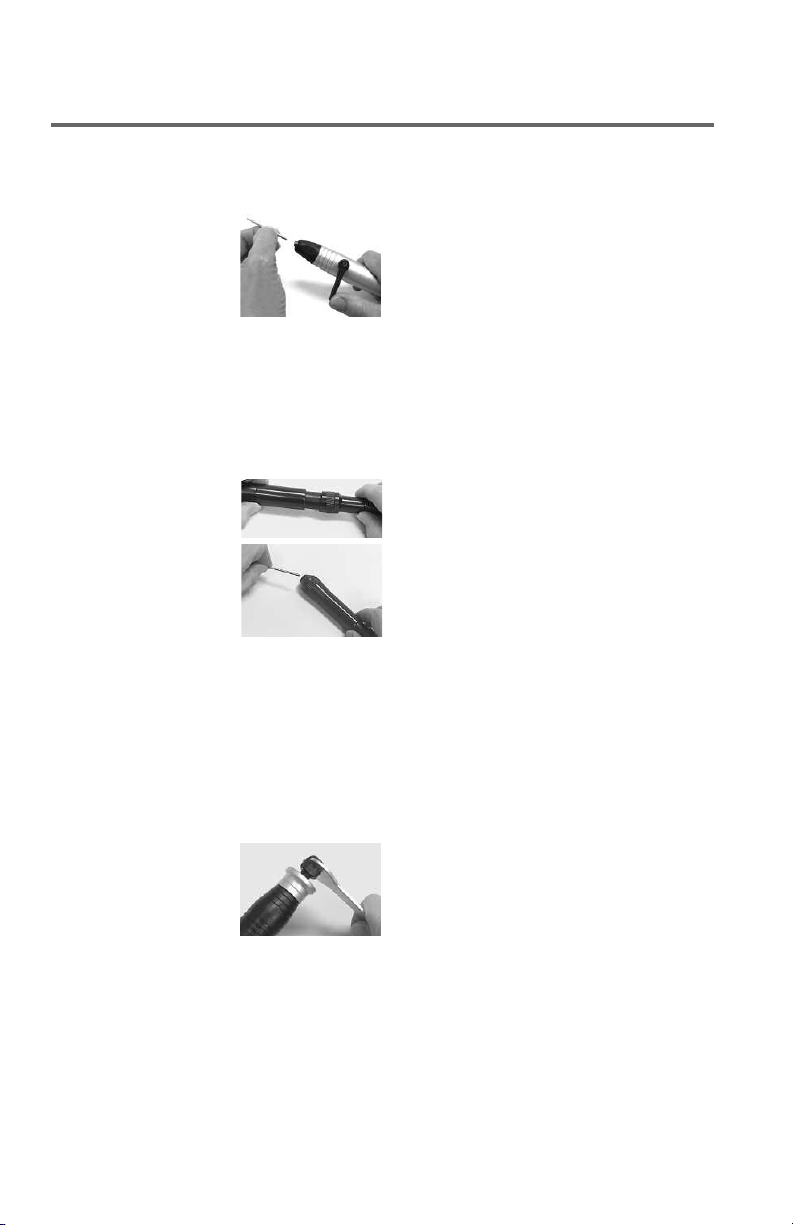
Quick Change Type – 10, 10D, 18, 18D, 18SJ,
20, 20D, 20SJ, 52, 52D, and 52SJ
Keep an accessory in these handpieces at all
times, during both operation and storage, or
damage to the collet and handpiece may result.
These handpieces accept only 2.35mm (3/32″)
shank accessories.
10 and 10D Handpieces:
To insert bur, turn lever 180º clockwise towards the
back (shaft connection end) of handpiece. Insert or
change a 2.35mm (3/32
180º forward counterclockwise. Make sure lever is
completely locked into the forward position.
change burs while handpiece is running.
18, 18D, and 18SJ Handpieces:
These handpieces have a
lever on the side of the
handpiece. Push the spring
loaded lever down to open
the collet and release the
shank of accessory (2.35mm or 3/32
accessory with the lever held down.
lever down while handpiece or fl
insert pin
®
, 30SJ,
″) shank bur and turn lever
ex shaft are rotating.
Remove pin.
Handpieces:
Never
″ only). Insert
Never push
9
Page 10
To minimize repetition, we sometimes drop prefixes associated with Foredom part numbers.
Officially, Motors begin with M. (M.SR), Handpieces with H. (H.30
®
), and Speed Controls with C. (C.FCT).
Attaching Accessories to Handpieces
Quick Change Type
20, 20D, 20SJ Handpiece:
This handpiece has a lever
action collet release mechanism. Wait for the motor,
flexible shaft, and accessory to come to a complete
stop before turning the lever to open the collet
and remove or insert accessory (2.35mm or
3/32
″ only). Turn lever 90˚ to left or right to open
collet and change an accessory. To close the collet turn the lever back to the position parallel to
the handpiece.
52, 52D, and 52SJ
Handpieces:
These quick change handpieces have a unique
push/pull collet release
mechanism for rapid
accessory changing
(2.35mm or 3/32
Wait for the motor, flexible shaft, and accessory
to come to a full stop before opening the collet.
After accessory has stopped rotating, pull the
top grip forward with one hand while holding the
bottom of the handpiece with the other. Remove
the accessory and insert the shank of the new
one fully into the collet. Push the top and bottom
portions together.
Chisel Type —
50 and 50C Handpieces
(50C includes set of
six chisels):
Inserting a chisel into this reciprocating handpiece
should be done while the motor is in the “off”
position, or with the handpiece disconnected.
Loosen the locking nut with the 12mm spanner
wrench provided by unscrewing it counterclockwise. Insert the tang fully into the plunger shaft.
Tighten the locking nut clockwise until tool is
held securely.
″ only).
Do not over tighten.
— continued
Handpiece Lubrication
(See page 8 for handpiece photos.)
8, 18, 20, 25, (25H), 28, (28H),
®
30
, (30H) 35, 43T, 44T, (44HT) and 52:
These handpieces have been permanently
lubricated. Their greased-shielded ball bearings
should absolutely not be lubricated.
listed in brackets are for use with Series TXH
and LXH models only.)
10 and 10D: Lubrication should not be
required for the first 2–3 months of continuous
use. Then, approximately every two weeks of
use, lubrication of the front and back ends of
the handpiece is required. Follow the detailed
instructions that come with your handpiece.
8D, 10D, 15D, 18D, 20D, and 52D
Handpieces with Duplex Spring Connections:
Approximately every 20 hours of operation
apply 1 or 2 drops of Foredom oil
MS10005) into the hole in the duplex spring
collar next to the sheath connector. This will
provide sufficient lubrication for both the
duplex spring connection and the
handpiece spindle.
15 and 15D: Clean off any dirt to prevent foreign matter from falling inside the handpiece.
Put two drops of Foredom oil into the oil hole
in the side of the housing. Run the handpiece
slowly to distribute the oil.
100 hours of use.
50 and 50C: After every 200 hours of use you
should clean and lubricate this handpiece. The
old grease must be cleaned off of the interior
cam chamber and replaced with new lubricant
(Part No. MS10008). Follow the detailed
instructions that come with your
chisel handpiece.
Visit www.foredom.net
How-To Videos on Foredom flex shaft
set-up, maintenance and operation!
(Handpieces
(Part No.
Lubricate ever
y
10
Page 11

General Accessory Recommendations
Foredom’s wide assortment of rotary accessories
makes your flexible shaft power tool very versatile.
Use it for grinding, sanding, carving, engraving,
brushing, cutting, buffing, and polishing on virtually
any material. The Foredom Accessory Catalog offers
the right accessories for your specific applications.
Accessories may be purchased from your local
dealer or directly from Foredom.
Always let the speed of the power tool do the work.
Avoid forcing the tool or applying too much pressure.
Experience will help you choose the right speed for the
work you are doing. It's always a good idea to practice
on a scrap piece of the same material you plan to use
to determine the best accessories and speeds.
Always follow the manufacturer’s RPM or speed
recommendations when selecting accessories.
Your motor is supplied with a variable speed control
that allows you to operate it at the most suitable
speed for each job. The motor has a maximum speed
rating of 18,000 RPM.
Always use an accessory which has the same
or a higher speed rating than your tool. Using an
accessory with a lower speed rating can result
in serious injury.
y Accessories and Motor Rotation:
Rotar
motor in forward and reverse can help to extend the
life of mounted abrasive points, Typhoon
and brushes.
Running the
®
burs, buffs,
Use only the forward motor direction for fluted
burs and cutters. Most will cut efficiently
only when turning in this direction.
Abrasive Points, Wheels, and Discs
Use Aluminum Oxide (red color) for fast cutting
on high-tensile, tough materials such as steel and
malleable iron. Also use on glass and porcelain, etc.
Aluminum Oxide (white color) points have an
extremely fine grit for producing a fine, high finish on
high-tensile materials including stainless steel and
glass.
Rubber Bonded Abrasive Wheels are used for
removing rust and for polishing with various grits. For
best results, use fi
speeds and coarser grits for stock removal at lower
speeds.
Abrasive Discs are for grinding, smoothing,
and cleaning glass, high speed steel, and other
tough materials.
Ruby Carvers have ruby crystals firmly bonded to
a metal frame. These long lasting abrasives provide a
smooth finish on hard materials such as steel,
porcelain, glass, acrylic, soft and precious metals
and wood.
ner grits for fi
nishing at high
11
Unique CeramCut Blue Stones are made from a
mixture of special man-made ceramic grain and
aluminum oxide bonded together. The ceramic
provides a faster cutting action and is more
durable so burs hold their shape longer than
standard abrasives. They are ideal for use on any
hard metal such as steel, stainless steel, chrome
cobalt, platinum and titanium, as well as on wood.
Unique V Stones have extra hard and long lasting
vitrified aluminum oxide and ceramic grain with
a special glass bead binder that makes them
extremely long lasting, cool running and very
aggressive — 40 to 60 grit. They work on the
same materials as CeramCut Blue Stones, but
much more aggressively.
Radial Bristle Discs from 3M have thin flexible
plastic bristles that get into hard to reach areas on
flat and curved surfaces. Use on metal, acrylic,
plaster, ceramics and wood without the need for
compounds. These long lasting abrasives come in
many size diameters and grits.
Ceramic Impregnated Polishing Wheels
for smoothing and polishing precious metals
including platinum, gold, and silver. They also work
on titanium, chrome cobalt, and all hard alloys.
Wheels are 7/8
″ in diameter and come in six grits.
Unique Scotch-Brite
Unique CW
TM
are used
Burs and Cutters
Vanadium Steel Cutters are suitable for all
materials except hardened steel and glass. They
are used for cutting grooves and countersinking in
soft materials, carving and hollowing woods, slotting and grooving woods, plastics, etc.
Cutters
are good for shaping, grooving, slotting
and cutting in wood, plastic and soft metals. Use
Carbide Burs on wood, plastic and tough alloys.
Carbide is generally referred to as the “hardest
man-made metal”.
High Speed Fluted Burs are used for fine detailed
work on metal and other hard materials. Generally
use medium speeds for stock removal and higher
speeds for finishing work and when using
smaller points.
groove, and trim metal, wood and ceramics.
Unique Typhoon®Carbide Burs provide very fast
and aggressive material removal. Made for use on
soft and hard woods, diestone, and plastics (do not
use Typhoon burs on metal). They have aligned
teeth that leave a smoother finish than other types
of non-fl
Cut-Off Wheels are used to cut off,
uted tungsten carbide burs.
Steel
Page 12

Drills
Step Drills are used to drill wood, precious metals,
mild steel, bone, and mother of pearl.
Coated Twist Drills
diamond coating, are used to drill extremely fine
holes in stone, ceramics, tile, glass, and hard metals.
, made of wire gauge steel with
Diamond
Plated and Sintered
Diamond Points and Discs
are used to remove stock from extremely hard
materials such as tungsten and tantalum carbide
cutting tools, dies and molds, broaches, and for
grinding and pre-polishing synthetic jewels and
precious metals, fiberglass, reinforced plastics, PVC
and ceramics. Sintered diamonds last far longer than
plated diamonds and can be re-sharpened as desired
with a wet dressing stone to expose new
diamond particles.
Sanding Drums, Bands, and Discs
These are used for removing rust, smoothing rough
surfaces and for sanding jobs on wood, plastic and
metal. (Avoid using too much pressure which will
cause clogging or a build-up on the work surface.)
For best results, use medium speeds for coarser
grits and larger diameters. Use higher speeds for
finishing work or with smaller sizes.
Ceramic Purple Coated Abrasive Bands and Discs
contain patented CubitronTMceramic aluminum oxide
mineral that sharpens itself with use. They last 2 to 4
times longer than traditional aluminum oxide discs
and remove material faster with less heat
and loading.
Unique 3M
Cotton or Felt Bobs and Buffs
Solid Felt Buffs or Bobs are used in combination
with gritty or smooth compounds for a variety of
buffing and polishing operations on plastic, wood,
and metal. They vary in shape and come in three
hardnesses — medium, hard, and rock hard.
Loosely-stitched Soft Cotton Buffs are used for
delicate work on precious metal and during polishing
operations. Generally use high speeds for cutting
down and buffing. Medium speeds are used for
more delicate, precise work and for polishing.
Brushes
Miniature Power Brushes are generally used on
metal surfaces and hard-to-reach areas. They are
ideal for deburring, surface finishing, edge blending,
roughening to create a good bonding surface, and
general cleaning. Use high speeds for cleaning and
deburring. Medium speeds are needed when
cleaning hard-to-reach areas and edge blending.
Unique Scotch-Brite
3M have thin flexible bristles that get into hard to
reach areas on flat and curved surfaces. Use on
metal, acrylic, plaster, ceramics and wood without
the need for compounds. They can sand, smooth,
polish, or burnish metal, plastic, or wood to a
bright finish.
TM
Radial Bristle Discs from
Compounds
Foredom has seven different compounds. In addition
to Emery, Tripoli, and Red and White Rouges, there
is
unique Platinum Blue for pre-polishing and cut-
ting down platinum and other metals, and for final
polishing
produces a deep luster on platinum, other metals,
and acrylics.
It produces a high luster on wood and
painted surfaces.
unique Platinum White (8000 grit) that
Carnauba is the hardest wax available.
2″ Wheels and Discs
for Angle Grinder Attachment
Foredom recently introduced several types of wheels
with 3/8
″
arbor holes for grinding, deburring,
shaping, and cutting on various materials. Also new
are various types of psa backed abrasive discs,
screens and velcro heads for sanding on wood,
metal, plastic, glass, stone and more.
Introduced in 2010, Foredom’s Angle Grinder
Attachment is
H.30H, or H.30SJ Chuck-Style Handpieces. It is
excellent for a broad range of sanding, polishing
and finishing work with 2
3/8
″ arbor hole wheels.
designed for use on the H.30®,
″ and smaller discs and
Bur and Tool Holders
Foredom has three rotating bur holders and two
small holders with covers. T
models have center cups for holding small tools
such as files and screwdrivers. A bur holder is the
perfect companion product for your collection of
burs, drill bits, and other accessories of various size
shanks.
The Foredom Accessor
accessories for your specific applications.
Accessories may be purchased from your local dealer or directly from Foredom. Contact:
The Foredom Electric Company,
16 Stony Hill Road, Bethel, CT 06801
Phone: (203)792-8622
Visit our online store at
wo of the rotating
y Catalog
www.foredom.net.
features the right
• Fax: (203)796-7861
12
Page 13
Maintenance Procedures
Always make sure your power tool
is unplugged during maintenance
procedures!
It is very important to routinely clean your
Foredom
(NOT the motor), especially in areas that
generate a lot of dust.
Dirt and improper lubrication are the most
common causes of poor operation and
excessive wear.
Always disconnect power tool before
cleaning or servicing.
Note: The motor has permanently
lubricated ball bearings and does
not require additional lubrication.
Routine Cleaning of Motors
Foredom Motors
need air circulation
through the motor
housing to remove
waste heat and cool
the windings. Inlet
and outlet slots
provide the means for air flow. However, saw dust
and conductive debris (like metal filings or gold
dust) can enter in through these slots. If not
cleaned regularly, dust can collect, making a
bridge between parts, causing an electrical short.
In high dust environments, Foredom
recommends cleaning the motor every
40 hours of use.
To remove dirt and dust buildup, motor brushes
should be removed, cleaned and replaced, and air
should be blown through the motor.
Routine Cleaning and
Lubrication of Flexible Inner Shaft
The shaft should be checked, wiped clean, and
relubricated with grease every 50 hours of use.
With every 200 hours of use, the shaft should be
thoroughly cleaned with solvent and lubricated.
Use Foredom flex shaft grease (p/n MS10006)
or high quality white lubricating grease.
®
Power Tool and lubricate the shaft
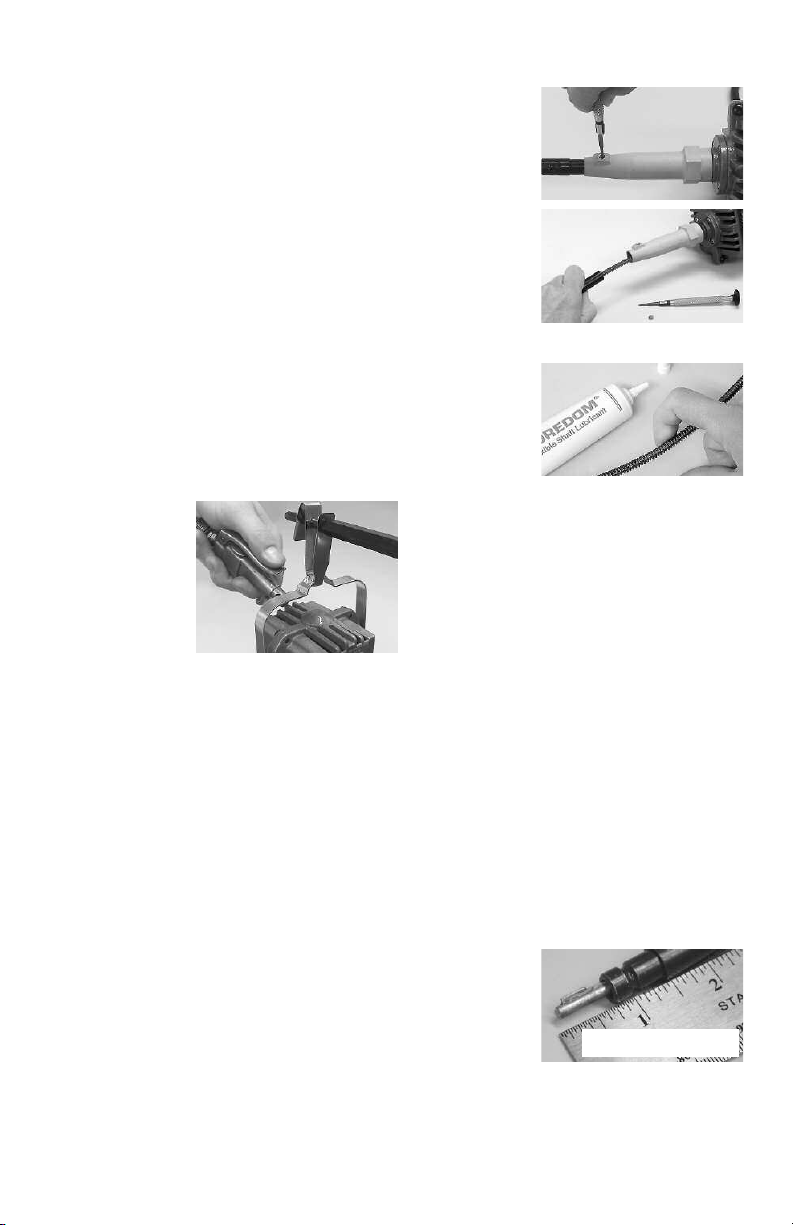
Exposing the Inner Shaft
1. Remove
h
andpiece
(see page 5).
2. Loosen set
screw on motor
connector.
3. Slide outer
sheath out of
motor connector
and wipe
shaft clean.
4. Apply a very
coating of
light
lubrication to shaft
starting at the top
and working
downward to
about one inch from the handpiece end. Apply
grease with your finger tip or small brush. Don’t
overdo, apply a light film of grease. Once the
machine is running, the shaft itself will spread the
grease. If too much grease is applied, the excess
will work its way into the handpiece and eventually seep out between the handpiece and sheath.
For this reason, apply a bit less near the handpiece end of the shaft.
Never operate the motor with the outer
sheath removed from the flexible shaft.
5. Replace and adjust sheath so that shaft key tip
extends 3/4
set screw in motor connector. See page 5, No. 2.
6. Clean outside of sheath by wiping with
a cloth.
7. Hang motor over a trash can and run it for
about 10 minutes before attaching the handpiece. This provides enough time for the grease
to warm up,
spread and drain
off. Wipe off any
excess grease at
tip end of sheath.
8. Re-attach
handpiece. See page 5.
″ (19mm) from sheath. Retighten the
IMPORTANT!
Be sure to watch shaft and sheath
maintenance videos on www.foredom.net
13
Page 14
Always make sure your power
tool is unplugged when conducting
maintenance procedures!
Replacement of
Worn Shafts and Sheaths
Shafts and sheaths last longer when they are not
used at sharp angles or loops, since wear occurs
at the points of greatest friction. There is no way
to avoid ultimate wear, and under normal conditions a flexible shaft machine may require several
replacement shafts and sheaths during its lifetime.
To expose the inner shaft follow steps 1, 2, and 3
on the previous page.
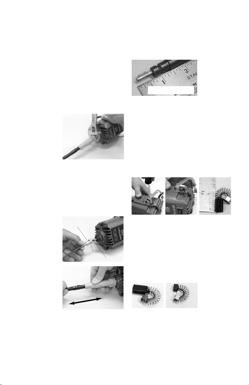
Next, remove motor
connector with 1
open end or
adjustable wrench.
Motor connector
has a left hand
thread and must
be turned clockwise (right) for removal.
Loosen set screw on the flexible shaft motor
coupling and slide shaft off the motor shaft.
″
Installation of New Shaft
1. After removing old shaft, loosen set screw on
motor
coupling
and slide
motor
shaft
.
the new flexible shaft motor coupling
coupling onto motor shaft.
2. Tighten set
screw securely
onto the flat of the
motor shaft.
3. Grease shaft prior
to putting on the
sheath. (See lubrication instructions on
page 13.)
4. Slide motor
connector back up
over the shaft and
tighten to the left
(counterclockwise).
5. Slide sheath over flexible shaft with plain
fitting directed toward the motor and into the
motor connector. (Each end of the sheath has a
tting. One is plain, the other has a groove
metal fi
around it to fit the handpiece.)
6. Adjust the shaft (page 5 and top right) and
tighten sheath set screw in motor connector
set screw
Visit www.foredom.net
How-To Videos on Foredom flex shaft
set-up, maintenance and operation!
Shaft and Sheath Adjustment
IMPORTANT!
Place the entire unit on a flat surface with
shaft and sheath extended straight.
Adjust the exposed tip of the flexible shaft
at the handpiece end so that it extends 3/4
(19mm) beyond the sheath.
This is done by moving the sheath in or out
of the motor connector. When the correct
adjustment is made, tighten the screw in
the motor connector.
Replacement of Motor Brushes
Motor brushes should be checked for wear
periodically. When new they are approximately
3/4
″ (19mm) long. Replace them when they
have worn to 1/4
disconnect motor power cord and unscrew the
brush caps. Remove the worn motor brushes,
replace with new motor brushes, and screw
motor brush caps back on. Be sure to replace
both motor brushes even if one of them is less
worn than the other.
New Motor Brush
Motor that needs
Brush
″ (6mm). To remove brushes,
replacement
″
14
Page 15
Recommended
Spare Parts & Supplies
For 1/6 hp Series SR, SRB and SRM
(115v & 230v)
• MSMK-10 Maintenance Kit which contains:
Flexible shaft (S-93)
Pair of motor brushes (MP132P)
Foredom flexible shaft grease (MS10006)
Owner’s Manual
Individual Parts
• Pair of motor brushes (MP132P)
• Flexible shaft (S-93)
• Outer sheath (S-77)
• Neoprene sheath (S-77N)
• Foredom flexible shaft grease (MS10006)
• Motor Connector (UA111P)
Repair Services
Authorized repair service is available at the
Foredom factory in Bethel, CT. Send items
for repair to the factory marked:
“Attention: Repair Department”
The Foredom Electric Company
16 Stony Hill Road, Bethel, CT 06801
Enclose the item(s), a packing list, and
information regarding the problem or repairs
required. Estimates of repair cost will be
made upon request.
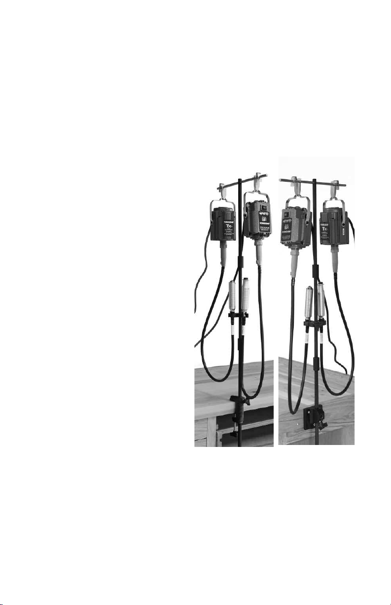
Motor Hangers
Foredom motor hangers have bases that can be
screwed or clamped to a bench. They keep
hang-up motors at just the right distance for
optimal use. Safety clips at the top prevent the
motor from jumping or twisting off at start up
and during use. Motors that slip off an open
hook can cause serious injury.
If the cost (labor plus parts) is more than
fifty percent of the price for a new replacement we will contact you and recommend
a trade-in offer.
Storage
Store your Foredom power tools in a DRY,
clean, dust-free area, and out of the reach
of children.
Visit www.foredom.net
How-To Videos on Foredom flex shaft
set-up, maintenance and operation!
Motor Hanger MAMH-1
can hang either one or
two motors. It comes
with
MABC-1 Clamp
that clamps onto a
workbench &
Handpiece Rest.
MAHR-2
15
Motor Hanger MAMH-2
can hang either one or
two motors. It comes
with
MABC-2 Base that
screws into a workbench and
Handpiece Rest.
MAHR-2
Page 16

Please retain your proof of purchase for warranty repairs.
LIMITED WARRANTY
Series SR and SRH Flexible Shaft Power Tools
Foredom warrants the Series SR and SRH Motors to be free of defects in material or workmanship for a period of 2 years after purchase. During the warranty period, the defective
product will be repaired or replaced without charge or, at our option, the purchase price will
be refunded. This warranty does not cover damage caused in transit or by accident, misuse,
or ordinary wear of shafts, sheaths, bearings, armature, and motor brushes.
ALL IMPLIED WARRANTIES, INCLUDING BUT NOT LIMITED TO WARRANTIES OF
FITNESS AND MERCHANTABILITY, ARE HEREBY LIMITED IN DURATION TO A PERIOD ENDING 2 YEARS FROM DATE OF PURCHASE, AND WE WILL NOT BE LIABLE OR RESPONSIBLE FOR ANY SPECIAL OR CONSEQUENTIAL DAMAGES.
Repair or replacement will be made at our option if the product is returned post-paid to:
The Foredom Electric Company
16 Stony Hill Road
Bethel, CT 06801
All warranty repairs must be done at the factory at the above address. We will not pay any
shipping or transportation charges. Handpieces have a 90 day warranty. Shafts, sheaths and
duplex springs are not covered by this warranty since they are especially sensitive to the
pressure and stress variables of the individual operator. This warranty only covers the origi-
chaser of the product. Some states do not allow limitations on how long an implied
nal pur
warranty lasts or the exclusion or limitation of incidental or consequential damages so the
above limitations may not apply to you. This warranty gives you specific legal rights, and you
may also have other rights which vary from state to state.
Contact Information
If you have a warranty issue with your Foredom power tool please use the contact
information below. For more information on Foredom machines, handpieces or accessories,
contact your local dealer. When no local dealer is available contact Foredom at:
The Foredom Electric Company, 16 Stony Hill Road, Bethel, CT 06801
Tel.: (203) 792-8622
Email: [email protected]
• Fax: (203) 796-7861
www.foredom.net
 Loading...