

Page 1
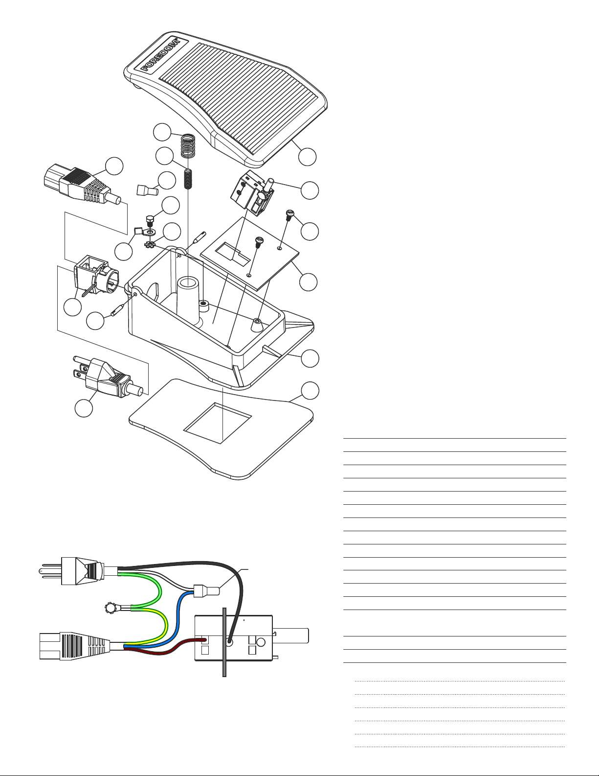
Parts List
C.SCH−2* & C.SCT−2
Foot Control, 230V
7
10
9
8
7
16
15
13
12
11
Instructions for Removing
and Replacing Trigger Switch
Disconnect Foot Control from Motor and Wall Outlet.
1.
With a punch and hammer drive two Pins (8) in until Cover (1)
lifts from each side of Bas e (5).
2.
Remove Cover and drive Pins outward with hammer and punch
to remove.
3.
Remove two Screws (3) from Bracket (4). After the wires have
been removed from the switch, as instructed in paragraph 4,
remove the switch from the board, insert the new switch in its
place, and follow the instructions in paragraph 5 and 6.
1
2
3
4
5
6
4.
On older Switches, all the terminals will be push-in, spring clamp
type. On newer Switches, Terminal 1 has a screw for fastening
the wire lead. To remove wires from the push-in terminals, insert
1.3mm [.05in] approximate diameter pin or the blade of a jeweler's
screwdriver all the way into the terminal socket to releas e the spring
clamp. Grasp the tool and wire and pull them together out of the
socket. If you have difficulty removing the wires from the push-in
terminals and you hav e wire-cutting, stripping, and soldering tools,
you can cut the wires off where they exit from the terminals. To
prepare the cut wires for installation into the replacem ent S witch,
strip them back exactly 8.25 mm [5/16 in], then apply solder to the
stripped ends to fuse the strands together.
5.
Insert new Trigger Switch into Bracket.
6.
Connect Wires to New Trigger Switch as shown in the
Wiring Diagram.
is exposed. On Screw Terminal 1, push the wire lead all the way
into the socket then tighten the screw firmly. Push the other
wire lead all the way into terminal 6. Pull on all the wires , m aking
sure they are secure.
7.
Install Bracket and Switch into Base using two Screws (3).
8.
Position wires around post of Base so wires will not
interfere with Cover travel.
9.
Install Cover over Spring (16) and align holes to Base.
Insert Pins (8) and seat them with hammer.
Push wires all the way in, so that no bare wire
Wiring Diagram
*C.SCH−2 is required for use with the latest
SR 230V Motors produced since May 2006.
AC Male Plug
To Power Source
BLK (BRN)
Wire
4
3
1
Bracket
Connector
Tigger Switch
2
GRN (GRN/YLW)
Attach Ground
Screw to Base
GRN/YLW (GRN)
Female Receptacle
to Motor
WHT (BLU)
BLU (WHT)
6
5
BRN (BLK)
}
FOREDOM The Foredom Electric Company
16 Stony Hill Rd., Bethel, CT 06801 • 203−792−8622
Fax: 203−796−7861
• www.foredom.net
CP11027
Form DN 1/11
DescriptionPart No.Item
1
2
3
4
CP11030
5
CP10690
6
CP10753
7
8
CP10584C
9
10
CP10580
11
CP10564
12
13
14
CP10542
CP10868
15
16
Cordset Option
CPOption20 CP10545 No Plug, Europe
CPOption21 CP10553 Male, United Kingdom
CPOption22 CP10554 Male, Continental Europe
CPOption25 CP10555 Male India 10A
CPOption26 CP10556 Male, Austrailia
CoverCP10691
Trigger Switch, 250VCP11027
Screw, 6−32 x 5/16"CP10571
Bracket
Base
Base Pad
Male Cordset or Substitute OptionCP10541
Hinge Pin
GrommetCP10578
Terminal Ring
Lock Washer, #8
Screw, 8−32 x 1/4"CP10563
Wire ConnectorCP11029
Female Cordset (SCT−2)
Female Cordset (SCH−2)
Set ScrewCP10562
SpringCP10588
Part No.
Description
Qty
1
1
2
1
1
1
1
2
1
1
1
1
1
1
1
1
 Loading...