

Master
Stone-Setting Kit
Instruction Handbook
AK820 Master Kit with
Foredom®H.30®handpiece
AK825 Master Kit without
Foredom®H.30®handpiece
®
FOREDOM
The Foredom Electric Company
16 Stony Hill Road,
203-792-8622
www
.foredom.com
• fax:
Bethel,
CT 06801
203-796-7861
Master
Stone-Setting Kit
Instruction
Handbook
The Allset prong, pavé and channel-cutting guides in this kit deliver precise,
repeatable accuracy and flexibility whenever they’re used. The result is higher
quality, defect-free stone settings done faster and easier than ever before!
Here’s what you’ll find with your Master Stone-Setting kit:
Non-Rotating Guide Assembly. This lightweight assembly is the heart of the Master kit. It attaches easily to a Foredom
H.30®handpiece and includes body, collar, shaft and L-bracket.
The Easy-Cut Prong Guide. Create level, uniform and precise cuts time after time with this remarkable prong-cutting aid.
Its unique design ensures a level and uniform-height cut on square, round or any other shape of prong. It also includes a new
stop guide that precisely controls the depth of each cut.
Channel-Setting Guides. Create perfectly contoured channel settings for round, square and baguette stones quickly and
easily with these precision guides. Kit includes three guides (small, large and knife-edge).
Prong Guides. Ensure the proper-depth cutting of prongs in single- or multiple-prong settings with these precise guides.
Includes 13 separate guides.
Pavé Guides. Let you create the cobblestone effect of pavé in half the time it would take by hand. Includes seven stainless
steel guides.
Allset Quality. Allset kits and components are made in the USA of highly durable materials and are versatile tools that stand
All of the cutting guides are made of the
up to multiple demands and configurations
highest quality stainless steel for a cleaner finish and a long, rust-free life.
.
Safety Notes
1. Always use eye protection when cutting prongs and channels with your AllSet Master Stone-Setting Kit or
when using any power tool.
2. Some prong and channel-cutting operations may require close placement of the hands to sharp
To avoid injury, please pay careful attention to hand placement, avoid distractions and do not operate
prong-cutting equipment without your full attention.
or safety and effectiveness with any power tool, maintain a clean work surface and general work area.
3. F
cutting edges
,
.
®
2

Introduction
The patented AllSet®guide assembly is a lightweight attachment that becomes part of a standard flexible shaft handpiece.
When properly installed, you can leave the collar and body
attached to the handpiece while doing other work with your
flex shaft. You may even decide to dedicate an extra H.30
handpiece exclusively to the AllSet guide.
To use the AllSet guide, simply slide the shaft and L- bracket
assembly into the body following the assembly instructions on
pages 4 and 5. When the handpiece is needed for another
operation such as polishing, simply loosen the rear shaft
locking screw and slide the shaft out of the body.
Assembling Your AllSet®Guide
The AllSet tool is carefully engineered to adjust for normal
manufacturing tolerance variations in the handpiece.Therefore,
you need to carefully tune the body of the AllSet to your handpiece by adjusting the collar set-screws, using the Allen Key
supplied with your AllSet Master Kit.These minor adjustments
in the collar set-screws will center the hole in the bracket in
front of the handpiece chuck. This procedure is explained in
Steps 6 and 7 of the assembly instructions on pages 4 and 5.
®
A Note About Burs
As a general rule, cutting seats for stones should be done with
low-speed burs. Vanadium steel burs are an excellent choice
because of their fine-vane design. This gives you greater control
while cutting the seat and helps eliminate the tendency of the
bur to grab and skip. As with most drilling operations, use a
low speed.
To achieve precise cuts during prong-setting, we recommend
using a flexible shaft machine with high torque at low speed
such as the Foredom®Series L or TX machine with your AllSet
tool. For cleaner cuts during channel-setting applications, you
will want to use a smaller bur and run it at a higher speed.
For this, we recommend using the Foredom Series SR.
Before You Start
Detach the H.30 handpiece from the flex shaft. Follow Steps 1
through 7 (pages 4 and 5) to install the AllSet guide assembly
on your H.30 handpiece.
®
Exploded View
Body
Shaft
Shaft
adjusting nut
L-bracket
H.30®handpiece
(supplied in Kit 820)
L-bracket
Guide
* You’ll need a flexible shaft machine fitted with a Foredom®H.30®handpiece.
(Copies of the Foredom H.30
not allow as good a fit.) Flex shaft machines are available separately.
ront guide
F
locking nut
®
Rear guide
locking nut
may have slight dimensional differences that do
Shaft
locking
screw
Collar
Set-screws
Body
Shaft
Assembled
View
L-bracket
3
90˚
Collar
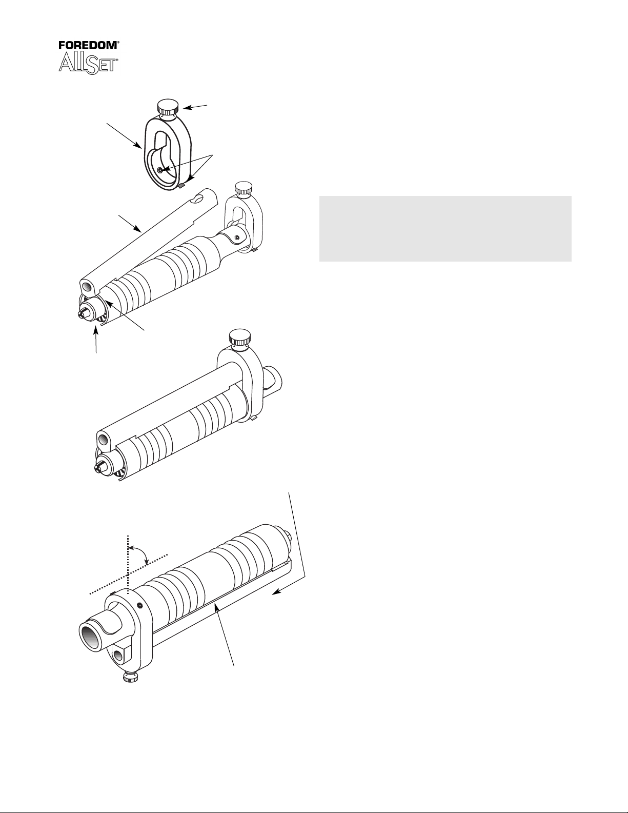
AllSet®Guide Assembly
Step 1:
Shaft locking screw
Unscrew both set-screws and shaft-locking screw, so none of
them extend into the opening of the collar (Figure 1).
igure 1
F
Figure 2
Figure 3
AllSet body
Chuck key
opening
Housing lip
Set-screws
Step 2:
Hook the front of the AllSet guide body over the front lip of the
handpiece housing, opposite the chuck key opening (Figure 2).
Lower the back of the AllSet body until it is flat against the
H.30®handpiece.
Please Note:
Be sure the front of the AllSet body is attached to
an unbent, undamaged section of the housing lip.
If the AllSet body does not lie flat on the handpiece,
it is not hook
ed properly over the housing lip.
Step 3:
Slip the collar over the back of the handpiece and AllSet body,
then push forw
ard against the handpiece housing (Figure 3).
Make sure the bevel on the inside edge of the collar is
facing forward.
Step 4:
Turn over the handpiece, body and collar assembly (Figure 4).
Screw in the shaft locking screw just enough to make sure it
is in the hole at the back of the body. Do not tighten it all the
way or the shaft will not slide completely into the body (see
Step 7). This screw is used to lock the shaft in position and does
not function to secure the collar on the body or handpiece.
Collar should be
perpendicular to
the handpiece
Figure 4
.
Push AllSet body firmly back
before tightening set-screws
(see step 5).
Make sure there is no gap
between the
handpiece housing.
AllSet body and the
Step 5:
While holding the body against the handpiece, push the front
of the body toward the collar to be sure it is still hooked over
the front lip of the handpiece housing. Evenly tighten the two
set-screws until the collar is centered from side to side on the
handpiece and the AllSet body is firmly against the handpiece
housing. Snug down the set-screws with the Allen Key included
in the kit. Do not over tighten.
Step 6:
Insert a 3/32″ (2.35mm) shank diameter bur in the handpiece
chuck (F
igure 5).
This bur will act as a reference for aligning the
AllSet guide. Since you will slip a guide over the bur, be sure
the bur head is smaller than the shank which is 2.35mm. A
2mm round bur is suggested.
Step 7:
Assemble the shaft adjusting nut and L-bracket as shown.
Insert the shaft (grooved end first) into the body of the
AllSet
(Figure 5). Loosen the shaft locking screw enough to allow the
shaft to slide past the locking screw. The bur should go through
the center of the hole in the L-bracket. Tighten the shaft
locking screw
.
4

Assembly instructions (continued)
Please Note:
Test for centering by sliding one of the prong stop
guides over the bur and into the hole in the L-bracket.
f the guide slides easily through the hole in the
I
L-bracket, the alignment is correct. The bur does not
need to be perfectly centered, but it should not rub on
the guide. The hole in the L-bracket is slightly larger
than the threaded portion of the guide to adjust for
minor variations in centering.
Installing Accessory Guides
Step 1:
Loosen the shaft locking screw and slide the shaft and
L-bracket assembly out from the bur. Slip the rear guide lock
nut over the bur (Figure 6). Slide the shaft and L-bracket back
into the body and tighten the shaft locking screw. It’s important
to tighten the shaft locking screw before aligning the guide
since the shaft will lift slightly when the screw is tightened.
Step 2:
To install a channel-setting guide or other accessory, slip the
guide over the end of the bur and into the hole in the L-bracket.
Tighten the rear guide lock nut to secure the guide, making sure
the guide is centered around the bur.
Step 3:
Loosen the shaft locking screw which allows the shaft to
slide freely. Adjust the guide using the shaft adjusting nut so
the bur protrudes from the guide (Figure 7). To change the
distance between the guide and the cutting edge of the bur,
adjust the guide using the shaft adjusting nut. Tighten
the shaft locking screw.
Please Note:
The smaller of the two basic channel-setting guides (see
page 12) is designed for use with small burs that have
tapered shafts below the bur head. Because the tip area
of the small channel guide is less than the 3/32
bur shank,
the guide will not allow burs to slip or go deeper
″ (2.35mm)
into the channel. Burs cannot be removed or inserted from
the front of the small guide.
The large channel guide is designed to accommodate larger
such as ball burs
,
burs
, and is especially useful in setting
stones with thicker girdles.
To Install Other Accessories
To install a table guide, the easy-cut prong guide or a pavé
guide, follow steps 2 and 3 (Figure 8).
Shaft
adjusting nut
L-bracket
Bur
able guide
T
Shaft
Channel
guide
Handpiece
Shaft
Bur
Body
Chuck
Body
Rear guide
lock nut
Guide
Prong guide
Shaft
locking
screw
urn shaft
T
adjusting nut
to adjust position
of the guide.
L-bracket
Figure 5
Shaft
locking
screw
Figure 6
Figure 7
Figure 8
Rear guide
Rear guide
locking nut
locking nut
5

The Easy-Cut Prong Guide
The AllSet®Easy-Cut Prong Guide helps ensure straight, uniform cuts on
each prong—every time! It’s completely adjustable and it positions the
setting precisely so the bur won’t grab or roll itself around the prongs,
ausing scratches. It adjusts to any stone shape and size. Perfect for 45°,
c
70° and 90° cuts, it allows you to cut perfect seats in the prongs of large
pendants, basket settings, solitaire mountings and much more.An
adjustable guide in back controls the depth of cut as well.
Use the Easy-Cut Prong Guide to:
• cut perfectly level stone seats regardless of the setting shape.
• gain precise, accurate control over the depth of cut so that finished
prongs are stronger.
• reduce stone breakage because you don’t have to force prongs
while setting.
L-bracket
As the bur rotates, it creates a counterclockwise force on the prong. The prong
guide allows movement only along the
guide’s edge.
Top view
stop guide
depth control
adjustment
The prong guide centers the prong for
the bearing cut; align the guide so that
the center of the prong is at the center
of the bur.
range of
adjustment
prong guide
angle adjustment
Side view
Exploded and assembled views of the Easy-Cut
Prong Guide mounted on the L-brack
attached to the H.30®handpiece.
et which is
Assembled view showing guide adjustments.
6

Using the Easy-Cut Prong Guide:
ake sure all prongs are at the same angle. File the tops of the
M
1.
prongs so they are the same height and level with one another.
2. Choose a low-speed bur that will make a cut appropriate for the
stone (usually a 90° hart bur). Fine-cut, low-speed burs will work
the best without chatter and skip.
3. Make the cuts by moving the prongs across the bur, perpendicular
to the inward direction of the cut. Cut about a third of the way
into the prong, depending on how thick the prongs are.
Many large colored stones have extra-thick girdles or some other irregularity. You will have to judge if cuts need to be wider or at different levels. Be
sure to mark the stone and the setting for position as you try the fit and
make adjustments. Well-cut stones benefit from settings made with AllSet
guides because there is little or no unusual torque or pressure from
uneven cuts.
Make sure each prong
s at the same angle
i
and is the same
length. File the top of
the prongs flat.
®
set the depth of cut into
prong with stop guide.
The end of the fence guide should
be positioned slightly underneath
the bur. This will prevent the prong
from slipping between the bur and
the guide.
Prong setting
with prong tips
on the table
Adjust the bur’s height for the
proper stone set (distance of cut
from top of prong).
Check to be sure that the piece sits level on the
table without wobbling.
Position the piece on the table using the prong
guide and depth control guide. Rotate the bur
slowly at first while making the cut into the prong.
Allen bolt
adjustment
When adjusting the guide for
prong width,
that the bur is centered with
the prong for consistent and
straight cuts.
it is very important
The stop guide (depth control) is
not necessary for all settings.
Use it whenever the depth of
the prong cut is critical
to the setting.
Rotational force
Centered prong
7

T
he Easy-Cut Prong Guide offers a wide range of adjustability.
Adjustment for prong height
Adjustment for
prong width
Adjustment
for depth of
cut into prong
same distance from top of prong
Rotational
force
Adjustment for smaller
settings/prongs
llen bolt
A
adjustment
Rotational
force
Adjustment for larger
settings/prongs
Allen bolt
adjustment
Rotational
force
Side view of ring setting showing center-cut prongs
with evenly cut heights.
Top view of ring setting showing center-cut prongs with evenly cut heights.
The Easy Cut Prong Guide produces consistent settings with perfectly even height and depth cuts.
Close-up views of cut prongs
(Easy-Cut Prong Guide vs. freehand cutting)
cut height
cut
depth
correctly
centered cut
cut height
correctly
centered cut
incorrect,
off-center cut
The result—
a perfectly
set stone!
incorrect,
off-center cut
8

Pavé Guide Set
The AllSet®Pavé guides make it quick and easy to create the field-of-
tones effect of pavé.
s
• Includes seven pavé guides, 2–5mm, in 0.5mm increments.
• Solid, non-rotating guides let you complete rows of settings in a
very short time and at the perfect depth for the material.
• Guides accept all 3/32″ (2.35mm) shank burs such as ball burs,
setting burs and hart burs.
Pavé Setting
Step 1:
Determine the diameter of the stones you will be using, making sure all
stones are the same size. Scribe the material with a crosshatch of lines
that are only slightly further apart than the diameter of the stones. This
pattern is usually a 60° offset design (Figure 9) but can be a square pattern. In any case, each line intersection must be slightly more than the
diameter of the stone from the closest adjacent intersection.
Figure 9
Figure 10
Step 2:
At each line intersection, drill through the material with a small drill
(smaller than the stone). This hole will provide a guide for the bur you use
to make the seat.
Step 3:
The AllSet pavé guide will provide a stop for the bur, making all the seats
exactly the same depth. Select a bur (usually a setting bur) the same size
as the stone. Choose one of the pavé guides that is a little larger than the
bur head.
handpiece. Adjust the pavé guide for the depth you need to make the seat
(Figure 10). This depth should allow the stone girdle to sit slightly below
the surface of the material.
drilled hole to guide the start of the bur
perpendicular to the work.
Step 4:
Place the stones in their seats to be sure they all fit. Finish the setting by
using a beading tool to push the material down between the stones
square pattern or any other spacing where there is material around the
stones, you will need to raise beads over the stones with a graver and
then finish each bead with a beading tool.
Mount the pavé guide in the
Mak
AllSet and then the bur in the
e all the seats in the material using the
Be sure to k
.
eep the tool
.
F
or a
9

Prong Guide Set
The AllSet®prong guides ensure proper depth cutting on all prongs in a
ingle setting with one quick cut. This allows you to produce more settings
s
with greater accuracy. Each prong is cut to precisely the same depth so the
stone will be absolutely level.
• 13 adjustable depth prong-setting guides allow you to use bur
sizes from 2.5mm to 8.5mm in 0.5mm graduated increments.
• Solid, non-rotating guides lets you hold settings firmly in place
with no twisting or grabbing as you cut.
• Guides accept all
Prong Setting
Step 1:
Make sure all prongs on the setting are evenly spaced and angled the
same. The distance between opposing prongs should be adjusted to
slightly less than the diameter of the stone at the height on the prongs
where you intend to cut the seat.
3
/32″ (2.35mm) shank burs.
Figure 11
Step 2:
Choose a setting bur that is just slightly smaller than the stone’s
diameter (too small a bur increases the chance that the bur will grab
and skip). The best burs are non-aggressive, fine cut burs. Select the prong
guide closest to the bur size that allows the head of the bur to fit down
inside the guide.
Step 3:
Mount the prong guide in the AllSet L-bracket (Figure 11). Insert the bur
through the guide and into the handpiece chuck. Tighten the chuck to
secure the bur.
Step 4:
Loosen the shaft locking screw and adjust the shaft with the shaft
adjusting nut so the shoulder of the bur is at the desired cut-depth below
the guide (Figure 12). You can always cut deeper, so set the depth less
rather than more for the first cut. The depth of the cut should end up
being a little deeper if the stone has a thick girdle.
Step 5:
Hold the setting securely and make sure you approach the prongs as
straight in as possible. Holding the setting with your fingers allows the
setting to move and align itself as the prongs come in contact
with the guide.
L-bracket
Figure 12
Prongs stop
flush against
guide for
a perfectly
level cut.
10

Channel-Setting Guides
Figure 13
Cut continuous channels on
straight or contoured pieces.
The AllSet®channel-setting guides allow you to cut perfect channels with
precisely the same depth on each side of the channel for level stone
setting. The set includes three adjustable depth channel-setting guides
for all channel-setting applications.
• The rounded tips of the two basic guides (small and large) make it
easy to cut continuous channels on straight or contoured pieces
(Figure 13).
• The new double knife-edge guide ensures perfect spacing of
separated stones.
Please Note: The smaller of the two basic channel setting guides
is designed for use with small burs that have tapered shafts below
the bur head. Because the tip area of the small channel guide is less
than the 3/32
″ (2.35mm) bur shank, the guide will not allow burs to
slip or go deeper into the channel. Burs cannot be removed or inserted
from the front of the small guide.
Figure 14
Front
iew
v
Knife
guide
Remove just enough of the corner edge to allow the stone to
pass as it is set into the channel. For deep or thick-girdled
stones, the lower corner edge may also be removed (use a
bur or graver to preserve smooth edges on the bearing cut).
Choose a bur
that is slightly
smaller than
your channel
width.
Secure stones in the
channel temporarily
with red sprue wax
before hammering.
ide
S
view
Move the knife guide
along the scribe marks
to create the stone
bearing-cut. Cut one
side at a time and
cut one side deeper
to allow access for
the stone.
Hammer the inside
edge of the channel
with a flat punch
or hammer
piece
hand
.
Figure 15
The large channel guide is designed to accommodate larger burs, such
as ball burs, and is especially useful in setting stones with thicker girdles.
Channel-Setting Tips:
Square Stones
For setting stones that will touch, you can cut a continuous channel
(Figure 13):
Step 1: Choose a hart bur with a diameter that will cut a channel to the
proper depth in the material for the diameter of the stones you are using.
Step 2: Select one of the two basic channel guides (small and large ) for
the size bur you are using (see note above).
Step 3: Adjust the distance between the guide tip and cutting edge of
the bur to the desired position of the channel.
Step 4: Cut each channel, making sure to keep the handpiece
perpendicular to the material.
Round Stones (using the knife guide)
For a setting where there will be space between round stones:
Step 1: Choose a hart bur that is slightly smaller than the
diameter of the stone (Figure 14).
Step 2: Scribe deep center marks on top of the channel w
use the knife-edge channel setting guide as illustrated (side view).
Step 3: Cut individual seats for each stone by sliding the knife
edge guide from one side to the other in the groove made by the
When setting the depth of the seat, be sure to allow a little
.
scribe
extra wall height for filing out the scribe marks (file out the scribe
°
30
marks before hammering).
Step 4: Set the stones in the channel (Figure 15). F
angle and hammer the top inside edge (not
channel w
all at a 30
°
the outside) to tighten the material over the stones.
ile the outside
all and
Set the leading
edge of the stone
into the first bearing
cut and lower the
opposite edge into
the opened
bearing cut.
he stone should
T
only just touch
the edge.
File a 30° angle
into the outside
edge of the
channel.
Hint:
Be sure to thoroughly clean shavings and metal debris from
out of the setting before putting the stone in place.
11

Customize Your Own Setting Operation with Allset®Kits!
Customize your AllSet just the way you want it! Choose exactly what you need to maximize your efficiency and
guarantee great results. If you already have a Foredom®handpiece or some of the equipment included in the kits,
just add the AllSet components you want from the selection described below.
Master Kit AK820
Quickly and easily achieve perfect results in all your stone-setting operations.
Includes a H.30®handpiece, AllSet handpiece attachments, complete set of
guides and video.
Master Kit AK825 Without Foredom H.30®handpiece.
Channel-Setting Kit AK828
AllSet handpiece
Cut perfect channels and maximize your production.
attachment for the H.30
knife-edge),
Channel Set Guides Only AK-829
guide locking nut,
®
three channel-setting guides
,
Allen wrench and instructions—in a fitted box.
Includes
, (small, large for baguette and
Prong-Setting Kit AK826
Produce consistent settings nearly 10 times faster than by hand! Includes AllSet
handpiece attachment for the H.30
locking nut, Allen wrench and instructions—all in a fitted box.
Prong Guides Only AK827
®
handpiece, 13 prong-setting guides, guide
Pavé-Setting Kit AK832
Allset handpiece attachment for the H.30®handpiece, seven pavé guides (for
setting a number of stones in a pattern to produce a field-of-stones effect),
guide locking nut,
Pavé Set Guides Only AK833
Allen wrench and instructions—all in a fitted box.
The Allset Accessory Video A-DVD125
Allset co-inventor, award-winning jeweler and tool designer, Jeffrey
Mathews, shows you how to use this revolutionary system to speed
stone- setting and increase accuracy.
orm 1270B n 5/08 Printed in USA.
F
31 minutes.
Easy-Cut Prong Guide Kit AK847
Allset milling table, guide locking nuts, Allen wrench and instructions—
in a fitted box.
Handpieces and guides sold separately
.
 Loading...