

Foredom K1020 User Manual
Repair Services
Other service or repairs should be done
b
y a competent repair person or you can
return your Foredom equipment to the
factory. If you wish, send your Micro
Grinder directly to the factory marked
"Attention: Repair Department". Include
a brief note describing the problem, your
name, address, phone numbers, and
email address.
Please retain your proof of
purchase for warranty repairs.
Replacement Part List
Motor Brush (pair) HP2-326
Chuck Key with handle HPCK-O
Warranty
Foredom warrants its product to be free of defects in material or workmanship
for a period of one year after purchase. During the warranty period, the defective
product will be repaired or replaced without charge or, at our option, the purchase
price will be refunded. This warranty does not cover damage caused in transit or by
accident, misuse, or ordinary wear.
ALL IMPLIED WARRANTIES, INCLUDING BUT NOT LIMITED TO WARRANTIES OF
FITNESS AND MERCHANTABILITY, ARE HEREBY LIMITED IN DURATION TO A PERIOD
ENDING ONE YEAR FROM DATE OF PURCHASE, AND WE WILL NOT BE LIABLE
OR RESPONSIBLE FOR ANY SPECIAL OR CONSEQUENTIAL DAMAGES.
Repair or replacement will be made at our option if the product is returned postpaid
The Foredom Electric Company, 16 Stony Hill Road, Bethel, CT 06801
to:
All warranty repairs must be done at the factory at the address above.We will not
pay any shipping or transportation charges.
This warranty only covers the original purchaser of the product. Proof of purchase
may be requested.
Some states do not allow limitations on how long an implied warranty lasts, so the
above limitation may not apply to you. This warranty gives you specific legal rights,
and you may also have other rights which vary from state to state.
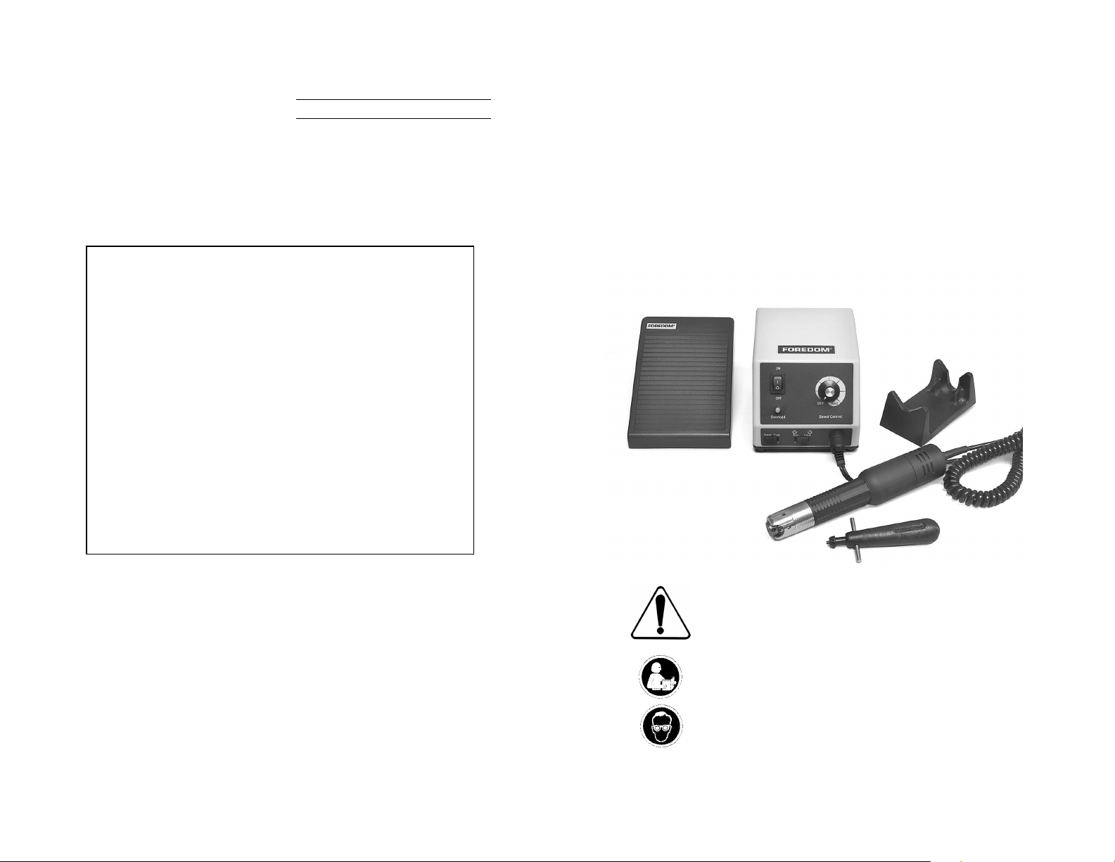
FOREDOM
Operation and
Maintenance Manual for
K.1020 Micro Grinder Kit
HP4-960
Foot Control
H.MH-120
Handpiece
HP4-917
Control
HP4-933
Cradle
®
HPCK-0
Chuck Key
Contact Information
For more information on Foredom machines, micromotors, handpieces or accessories,
contact your local dealer. When no local dealer is available, write, call, fax or email:
The Foredom Electric Company, 16 Stony Hill Road, Bethel, CT 06801
203-792-8622,
When no local dealer is available you can also visit our website at
www.foredom.com for Foredom replacement parts.
F-1224 n 5/10 Printed in U.S.A.
Fax: 203-796-7861,
customerservice@blackstoneind.com
Email:
For Your Safety:
Read this Manual before operating your
Foredom Micro Grinder Power Tool.
Always wear eye protection while using
the Foredom Micro Grinder Handpiece.
www.foredom.com
Safety
Instructions
A Micro Grinder Handpiece is a high
speed rotary power tool which can be
dangerous and cause serious injury if it
is not used properly.
NEVER operate it without wearing
eye protection.
• ALWAYS wear proper eye and
face protection.
• ONLY use accessories rated for
speeds of 20,000 rpm or higher
when operating this micromotor.
• ALWAYS observe the manufacturer's
maximum speed rating when using
any accessory.
• NEVER use or continue to use any
accessory which appears to be damaged,
loose, vibrating, bent, or out of balance.
Inspect each accessory for cracks or flaws
before use.
• ALWAYS insert the shank or arbor of an
accessory or mandrel into the chuck of the
handpiece as far as possible in order to
provide proper support and close the chuck
DO NOT use accessories with
securely.
shanks that are less than 1
• NEVER use excessive side pressures
which may tend to bend or break the shank
or arbor of an accessory
the accessory do the work.
• DO NOT stall the motor by jamming or
using excessive pressure on the mounted
point, buff, wheel or accessory
result in damage to the motor.
• WEAR a dust protector to prevent the
inhalation of harmful dust or debris from
grinding, carving or other operations performed with this power tool.
• DO NO
handpiece motor with cloth or tape. Air
must pass freely through the intake and
exhaust ventilation slots to properly cool
the motor
• If the power cord or plug to the
handpiece is damaged,
immediately
damaged power cord.
• USE a dust collector (vacuum system) to
pull sawdust,
aw
box and handpiece intake vents.
T
cover the ventilation slots or
.
.
NEVER operate with a
ay from the work area and the control
grinding dust,
″ long.
. Let the speed of
. This can
repair or replace
or other debris
• NEVER plug the Handpiece into
the Variable Speed Foot Control
Connection Port on the back of
the Control Box.
• ALWAYS plug the Handpiece into
the Handpiece Connection Port on the
Front of the Control Box.
• DO NOT operate the handpiece in the
presence of any flammable liquid or gas.
Assembly Instructions
Do not plug into a power outlet
before connecting the handpiece
or foot pedal. Check to see that the
voltage selector switch on the back
of the control box, is set to the
voltage to be used–110 or 220 volt.
Figure 1 Front Panel
Illuminated
Power
On/Off
Switch
Overload
Indicator
Light
Speed Control
Selector Switch
(Hand or Foot)
Rotation
Selection
Switch
Figure 2 Rear Panel
V
ariable Speed
oot Control
F
Connection Port
On/Off F
Connection
Port
oot
Speed Dial
Handpiece
Connection
Port
Power
Cord
Voltage Selector
Switch-110 or
220 volt
Connecting Handpiece
A
ttach the Micro Grinder handpiece to
the control box by plugging the coiled cord
into the Handpiece Connection Port on the
lower right side of the front control panel
(Figure 1). Use keyway for proper alignment
when plugging in the cord.
NEVER plug the handpiece into the
Variable Speed Foot Control
Connection Port.
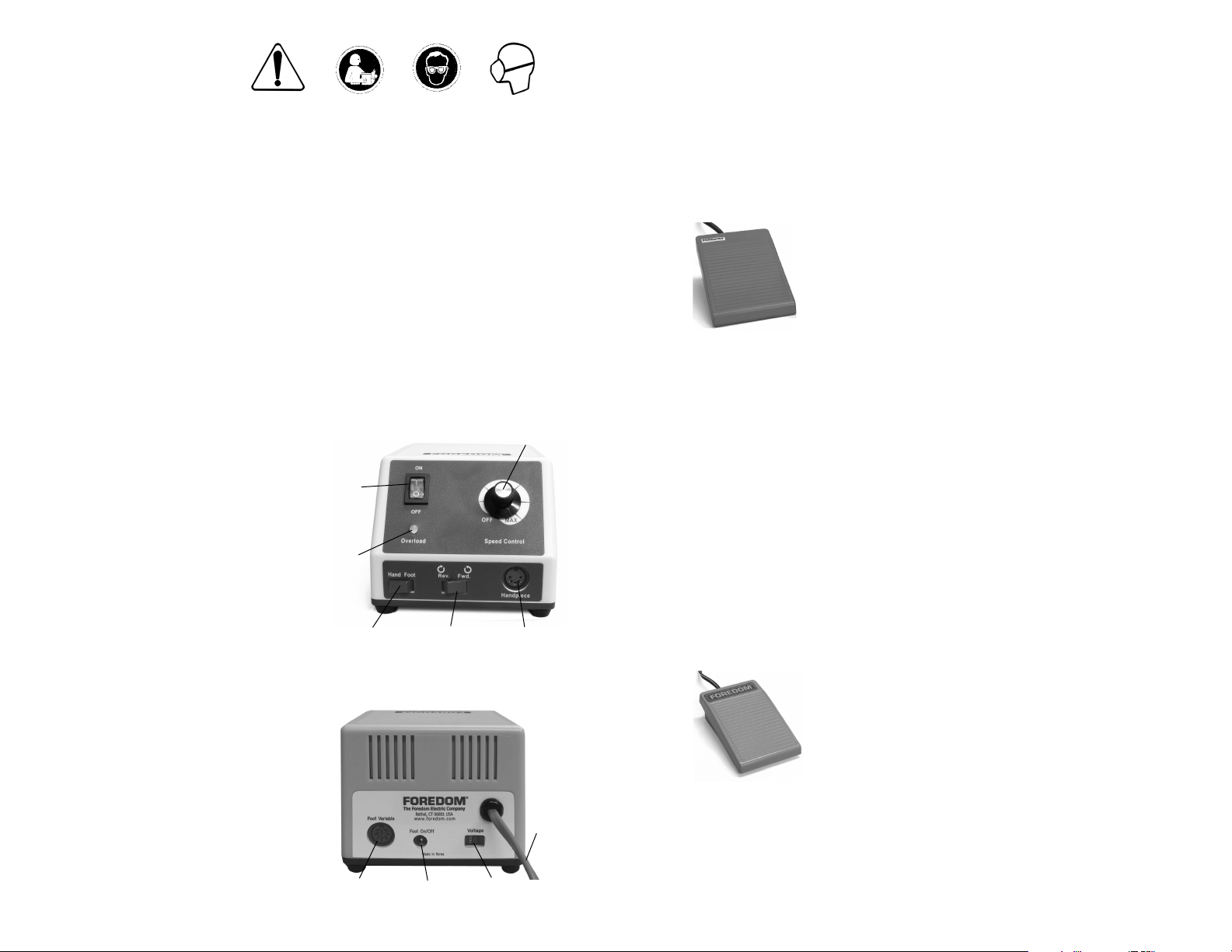
Connecting
the Variable
Speed Foot
Control
The Variable Speed
Foot Control is
suitable for either
110 or 220 volt
by inserting the connector into the Variable
Speed foot control connection port on the
rear panel of the control (Figure 2) using
the keyway for proper alignment. It is not
necessary to have the foot pedal connected
to the control box to operate the dial speed
control. The Micro Grinder control and
handpiece are now ready to operate.
operation. Attach it
Connecting Power Cord
Before connecting the power cord plug
(Figure 2) to a power outlet, select the
proper voltage (110 or 220v) on the back
of the control box. Put the On/Off Selector
Switch in the OFF position and turn the dial
speed control to the OFF speed position.
Now plug in the power cord to an
current outlet.
AC
Connecting Optional On/Off
Foot Switch This switch (p/n
HP4-927) is available separately
and attaches by
inserting the
connector into
the On/Off foot
connection port
on the rear panel
HP4-927
keyway for proper alignment.This switch
allows you to turn the motor on and off
without changing the speed set by the dial.
of the control
igure 2) using
(F
Operating Instructions
for HP4-917 Control Box
1. Power On/Off Switch
When the Power On/Off Switch is in the ON
position the switch lever will light up.
switch must be in the ON position for
the handpiece to run with either the
dial speed control or the foot speed
control selected.
Always turn the Dial and Power On/Off
Switch to the Off position when not
in use.
2. Hand or Foot
Selector Switch
With the Dial and Power On/Off Switch in
the OFF position, select either foot or hand
speed control.
• With the Speed Control Selector Switch in
the Hand position, the handpiece will run at
the speed set by the Dial Speed Control.
• With the Speed Control Selector Switch in
the Foot position, the handpiece will not
operate until the Foot Pedal is depressed.
3. Forward/Reverse
Rotation Selection Switch
With the Power On/Off Switch in OFF
position, select the desired handpiece
rotation by moving the switch to Fwd. for
FORWARD or Rev. for REVERSE rotation.
Changing handpiece rotation
direction while in operation is
not recommended.
4. Regulating Speed
• The Dial Speed Control varies the
speed of the handpiece from minimum to
maximum when the Speed Control Selector
Switch is in the Hand position.
• The Dial also controls the maximum
speed that can be reached when using a
foot pedal.
To achieve maximum speed with a foot
pedal, the dial speed control must be
turned all the way to the Max setting.
5. Handpiece
Overload Protection
he red overload light will come on with an
T
audible alarm, and the handpiece will stop
when too much load is placed on the
handpiece. Immediately turn off control by
putting the Power ON/OFF switch in OFF
position. Put power switch in ON position
again when overload condition is correct-
here may be a time delay of several
T
ed.
seconds before the overload trip resets.
This
 Loading...