

Page 1
Section 03-01: Engine , 3.8L 1995 Windstar Worksh op Manual
3
1995 Windstar
6/3/2009
http://www.fordtechservice.dealerconnection.com/pubs/content/~WSSW/~MUS~LEN/20/S
...
REMOVAL AND INST ALLATION
Engine Front Cover
If the engine front cover (6019 ) is being removed to check timin g chain deflection, refer to Timing Chain Deflection Procedure as outlined in Section 03-00.
SPECIAL SERVICE TOOL(S) REQUIRED
Crankshaft Damper Remover T58P-6316-D
Vibration Damper and Seal Replacer T82L-6316-A
Vibration Damper Remover Ad apter T82L-6316-B
Removal
Description Tool Number
1. Remove engine (6007) from vehicle. Refer to procedure in thi s section.
2. Loosen drive belt tensioner (6B209) and drive belt (8620) .
3. Remove water pump pulley retaining bolts and water pump pu lley (8509) .
4. Remove retaining bolts and disconnect heater water outlet tube (18663) from water pump (850 1) .
5. Disconnect electrical connector at camshaft position sensor.
6. Disconnect electrical connector at crankshaft position sensor (CKP sensor) (6C315) .
7. Remove retaining bolt and disconnect radiator lower hose tube (8291) from water pump .
NOTE: If the vibration dampe r and crankshaft pulley have to be separated, mark the vibration damper and crankshaft p ulley so that they may be reassembled in the
same relative position. This is important as the vibration damper and crankshaft pulley a re initially balanced as a unit.
NOTE: If the vibration dampe r is being replaced, check if the original vibration damper has balance pins installed. If so, new balance pins (6A328 or eq uivalent) must be
installed on the new vibratio n damper in the same position as the original vibration damp er. The crankshaft pulley (new or original) must also be instal led in the same
relative position as originally installed.
8. Remove crankshaft pulley (6312) and vibration damper assemb ly using Crankshaft Damper Remover T58P-6316-D and Vibrat ion Damper Remover Adapter T82L-6316-B.
9. Remove four retaining bolts and remove brace from A/C bracket and P/S bracket.
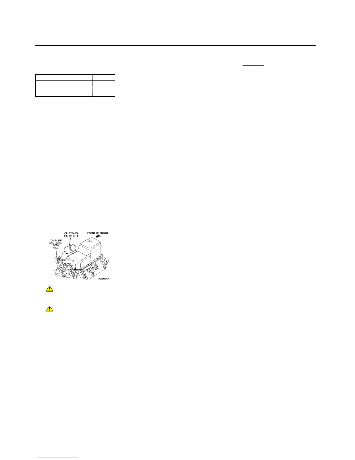
10. Remove oil bypass filter (6714) .
CAUTION: The engine front cover cannot be removed witho ut lowering the oil pan (6675 ) .
11. Remove oil pan . Refer to procedure in this section.
CAUTION: Do not overlook th e engine front cover retaining bolt located behind the oil pu mp and filter body (6603) . The engine front cover will break if pried upon
and all retaining bolts are no t removed.
12. Remove engine front cover retaining bolts. It is not necessary to remove water pump .
13. Remove engine front cover and water pump as an assembly.
14. Remove engine front cover gasket and discard.
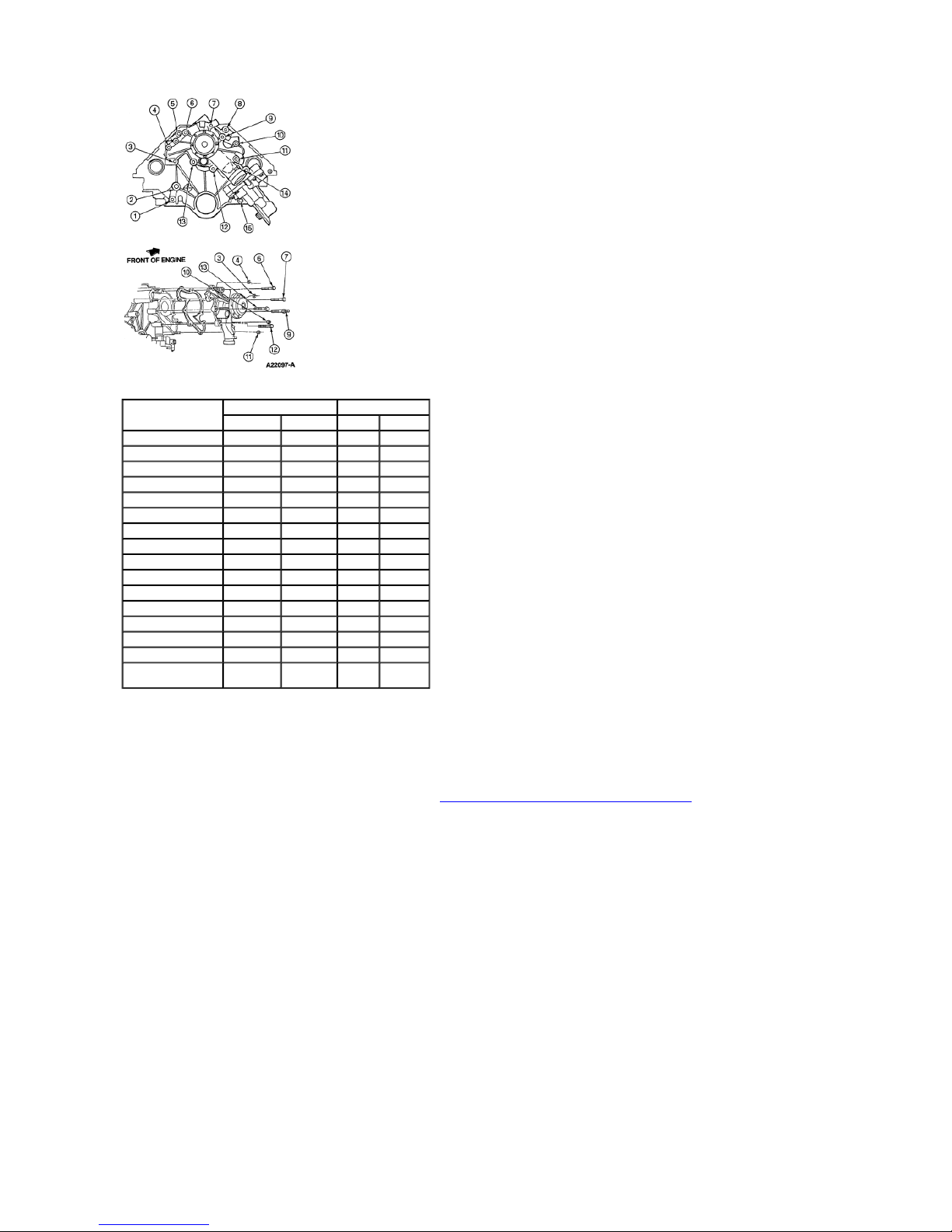
Water Pump Tightening Sequ ence
Page 2
3
1995 Windstar
6/3/2009
http://www.fordtechservice.dealerconnection.com/pubs/content/~WSSW/~MUS~LEN/20/S
...
Fastener and Hole No.
1 — 4 N805112 Stud
2 — 2 N805112 Stud
3 2 9 N804757 Stud
4 1 8 N804757 Stud
5 — 10 N605787 Bolt
6 9 15 N605908 Bolt
7 8 16 N605908 Bolt
8 — 11 N807611 Stud/Bolt
9 7 17 N804756 Bolt
10 6 1 N805275 Stud
11 5 7 N804757 Stud
12 4 13 N605908 Bolt
13 3 14 N605908 Bolt
14 — 6 N804839 Bolt
15 — 5 N804841 Capscrew
3,4,10,11 2,1,
Installation
NOTE: Lightly oil all bolt and stud bolt threads before instal lation except those specifying special sealant.
1. Clean gasket surfaces on the engine front cover and cylinder block (6010) .
If reusing the engine front cov er , replace crankshaft front seal (6700) . Refer to Crankshaft Pu lley and/or Damper and/or Crankshaft Front Seal in this section.
2. If a new engine front cover is to be installed:
Install oil pump and filter body .
Clean water pump gasket surface. Position a new water pump housing gasket (8507) on the eng ine front cover and install water pump . Install water pump retai ning bolts.
Tighten to 20-30 Nm (15-22 lb-ft).
3. Lubricate crankshaft front seal with clean engine oil XO-10W30-Q SP or -DSP or equivalent meeting Ford specification ESE-M 2C153-E.
NOTE: Gasket and Trim Adh esive D7AZ-19B508-B or equivalent meeting Ford specifica tion ESE-M2G52-A is recomme nded to hold the engine front cover gasket (6020)
in position while the engine front cover is installed.
4. Position a new engine front cover gasket on the cylinder block and install the engine front cove r / water pump assembly using dowels for proper alignment.
5. Install the engine front cover ret aining bolts. Tighten to 20-30 Nm (15-22 lb-ft). Install the capscrew (Part No. N804841) nearest the oil bypass filter flange last, a nd tighten last. Apply
Loctite® or equivalent to bolt prior to installation. Refer to illustrat ion under Step 13 of removal procedure.
6. Install oil pan as outlined.
7. Install oil bypass filter .
8. Coat pulley sealing surface with clean engine oil XO-10W30-Q SP or -DSP or equivalent meeting Ford specification ESE-M2C153-E.
NOTE: When using silicone ru bber sealer, assembly must occur within 15 minutes after sealer application. After this time, the sealer may start to setup, and its sealing
effectiveness may be reduced.
9. Apply a small amount of Silicone Gasket and Sealant F1AZ-19562-A or equivalent meeting Fo rd specification WSE-M4G320-A2 to crankshaft keyway.
10. Position crankshaft key (6B316) in the crankshaft keyway.
Water Pump Front Cover Part No. Part Name
6,5
Hole No. Fasteners
9,8,
N804758 Nut
1,7
Page 3

11. Install the crankshaft pulley using Vibration Damper and Seal Replacer T82L-6316-A.
3
1995 Windstar
6/3/2009
http://www.fordtechservice.dealerconnection.com/pubs/content/~WSSW/~MUS~LEN/20/S
...
12. Install crankshaft pulley retaining washer and bolt. Tighten bolt to 140-180 Nm (103-132 lb-ft ).
13. Install pulley to vibration damper, if removed. Tighten retaining bolts to 26-38 Nm (19-28 lb-ft).
14. Install brace to A/C bracket and P/S bracket. Tighten three M 8 retaining bolts to 20-30Nm (16 -22 lb-ft). Tighten one M10 retaining bolt to 10-54 Nm (31-41 lb -ft).
15. Connect radiator lower hose tube . Tighten bolt securely.
16. Connect crankshaft position sensor electrical connector.
17. Connect camshaft position sensor electrical connector.
18. Connect heater water outlet tube to water pump . Install retaining bolts and tighten to 8-11.5 Nm (71-102 lb-in).
19. Install water pump pulley and retaining bolts. Tighten bolts to 40.3-54.7 Nm (30-40 lb-ft).
20. Position drive belt over pulleys and drive belt tensioner . Refer to Section 03-05.
21. Install engine into vehicle. R efer to procedure in this section.
 Loading...