

Ford VSG-411, VSG-413 Service Manual

I
Power
Products
VSG-411 I41 3
ENGINE
SERVICE
MANUAL
FPPO-194-264
REVISED OCT. ‘89
IMPORTANT SAFETY NOTICE
Appropriate service methods and proper repair procedures are essential for the safe, reliable operation of all
motor vehicles as well as the personal safety of the individual doing the work. This Shop Manual provides
general directions for accomplishing service and repair work with tested, effective techniques. Following them
will help assure reliability.
There are numerous variations in procedures, techniques, tools and parts for servicing vehicles, as well as in the
skill of the individual doing the work. This Manual cannot possibly anticipate all such variations and provide
advice or cautions as to each..Accordingly, anyone who departs from the instructions provided in the fvfanual
must first establish that he compromises neither his personal safety nor the vehicle integrity by his choice of
methods, tools or parts.
NOTES, CAUTIONS, AND WARNINGS
As you read through the procedures, you will come across NOTES, CAUTIONS, and WARNINGS. Each one is
there for a specific purpose. NOTES give you added information that will help you to complete a particular
procedure. CAUTIONS are given to prevent you from making an error that could damage the engine. WARNINGS remind you to be especially careful in those areas where carelessness can cause personal injury. The
following list contains some general WARNINGS that you should follow when you work on an engine.
l
Always wear safety glasses for eye protection.
l
Use safety stands whenever a procedure requires you to be under the unit.
l
Be sure that the ignition switch is always in the OFF position, unless otherwise required by the procedure.
l
Set the parking brake when working on a vehicle. If you have an automatic transmission, set it in PARK unless
instructed otherwise for specific operation. If you have a manual transmission, it should be in REVERSE
(engine OFF) or NEUTRAL (engine ON) unless instructed otherwise for a specific operation. Place wood
blocks (4” x 4” or larger) to the front and rear surfaces of the tires to provide further restraint from inadvertent
vehicle movement.
l
Operate the engine only in a well-ventilated area to avoid the danger of carbon monoxide.
l
Keep
belts.
yourself
and your clothing away
from moving parts, when the engine is running, especially the fan and
l
To prevent serious burns, avoid
catalytic converter and muffler.
contact
with hot
metal parts such as the
radiator,
exhaust
manifold, tail
pipe,
l
Do not smoke while working on the vehicle.
l
To avoid
injury, always
a vehicle. Tie work on
remove rings, watches, loose hanging
long hair securely behind the head.
jewelry, and loose clothing
before beginning
0 Keep hands and other objects clear of the radiator fan blades. Electric cooling fans can start to operate at any
time by an increase in underhood temperatures, even though the ignition is in the OFF position. Therefore,
care should be taken to ensure that the electric cooling fan is completely disconnected when working under
the hood.

Introduction
This Service Manual provides the service technician with, information for
the proper servicing of the Valencia industrial Engine.
In general, this manual covers the servicing of the engine and
associated standard equipment. In many cases, engines are supplied
with accessories and equipment that are unique to the application. If
service information is ever required on such unique accessories or
equipment it is suggested that the Ford Power Products Operations of
Ford Motor Company be contacted. The proper information will either be
forwarded or the Service Technician will be advised where it can be
obtained.
The information in this manual is grouped in sections according to the
type of work being performed. The various sections are indicated in the
index. In addition, each section is subdivided to include topics such as
diagnosis and testing, cleaning and inspection, overhaul, removal and
installation procedures, disassembly and assembly procedures, and
service specifications.
Where the terms “Right” or “Left” occur in this publication, they refer to
the respective sides of the engine when viewed from the rear or flywheel
end.
Pistons and valves are numbered from the front or timing cover end of
the engine commencing at Number
1.
FORD MOTOR COMPANY
FORD POWER PRODUCTS OPERATIONS
FORD PARTS AND SERVICE DIVISION
3000 SCHAEFER ROAD
DEARBORN, MICHIGAN
The descriptions and specifications contained in this manual were in effect at the time the book was
released for printing. Ford Motor Company reserves the right to discontinue models at any time, or
change specifications or design, without notice and without incurring obligation.
Note: The recommendations and suggestions contained in this pubiication are made to assist the
distributor in improving his distributorship parts and/or service department operations. These
recommendations and suggestions do not supersede or override the provisions of the
Warranty and Policy Manual and in any cases where there may be a conflict, the provisions
of the Warranty and Policy Manual shall govern.
Litho in U.S.A.
48121
Rev. October, 1989

l-01
VSG GASOLINE ENGINE
PART
1 Basic Engine
PART
2 Ignition System - Breaker Type
PART 2A
PART 2B
PART
Ignition System - Solid State ......
Ignition System - Distributorless
Fuel System
3
.....................
....
...
......................
PART 1 Basic Engine
DIAGNOSIS AND TESTING’ : : : : : :
Camshaft Lobe Lift ......................
Compression Test .......................
Crankshaft End Play .....................
Flywheel Face Runout ...................
Camshaft End Play ......................
OVERHAUL ..............................
Cylinder Head ..........................
Valves .................................
Camshaft. ..............................
Crankshaft. .............................
Pistons, Pins and Rings ..................
Valve Rocker Arm and/or Shaft
Assembly
Push Rods
Cylinder Block
CLEANING AND INSPECTION .............
Intake Manifold
Exhaust Manifolds
Valve Rocker Arm and/or Shaft
Assembly .............................
Push Rods
Cylinder Heads
Tappets ................................
Timing Chain and Sprockets ..............
Camshaft. ..............................
Camshaft Bores
.............................
.............................
..........................
..........................
.......................
.............................
.........................
.........................
..............................
: : : :
......
Basic Engine
PAGE PAGE
l-01
2-01
2A-01 PART
28-01
3-01
PART 4
PART
PART
PART
Connecting Rods
Pistons, Pins and Rings ..................
Main and Connecting Rod Bearings
Cylinder Block ..........................
Oil Pan
Oil Pump ...............................
REMOVAL AND INSTALLATION ............
Valve Rocker Arm Cover, Rocker Arm
Intake Manifold
Exhaust Manifold ........................
Cylinder Head ..........................
Valve Spring, Retainer and Stem Seal
Water Pump
Cylinder Front Cover and Timing Chain, or
Adjusting Valve Clearances ...............
Crankshaft Front Oil Seal
Camshaft and/or Valve Lifters .............
Camshaft Bearings ......................
Oil Pan .................................
Flywheel Ring Gear
Crankshaft Rear Oil Seal
Pistons and Connecting Rods
Oil Filter ................................
DISASSEMBLY AND ASSEMBLY ...........
Charging System .................
5
Starting System ..................
6 Governor ........................
7
Cooling System ...................
8
Specifications and Special Tools ....
...............................
........................
.................................
and/or Shaft
Crankshaft Sprocket
..........................
..........................
............................
...................
................
.....................
.................
.................................
.............
.......
.....
l-01
4-01
5-0’1
6 01
-
7101
8-01

Basic Engine
l-02
IDENTIFICATION
An Identification Decal (Fig. 1) is affixed to the left side of the
rocker cover of each engine. The decal contains the engine serial
number which identifies this unit from all others. Next is the
engine displacement which determines the engine specifications,
then the model number and S .O. or special options which determine the parts or components required on this unit. Use all
numbers when seeking information or ordering replacement parts
for this engine.
FIG. 2 A - Serial Number
B
- Engine Code
C
- Engine Build Date
FIG. 1 Identification Decal
Identification of the cylinder block and therefore of the basic
engine type can be made by reference to the stampings on the left
rear top edge of the cylinder block (Figure 2).
The engine code will begin with a “G.” This will indicate that it
is a 1.1 liter engine.
The engine build date follows the corporate system. Example:
“4K26”. The first number indicates the year. The letter indicates
the month in alphabetical sequence, A January, B February, etc.
omitting I. The last two numbers are the day of the month.
DESCRIPTION
The engine is a water-cooled, 4 cylinder, 4 stroke, in-line
gasoline engine. The cylinder head in which the combustion
chambers are located is of a cross-flow type, the fresh fuel/air
mixture is drawn in on one side and burnt gases are passed into the
exhaust system on the opposite side.
The valves are suspended in the cylinder head and are operated
by means of tappets, pushrods and rocker arms.
The valves are disposed in an alternating pattern in the cylinder
head starting with an exhaust valve by the thermostat housing.
The three-bearing camshaft is located on the right side of the
cylinder block and driven by roller chain from the crankshaft.
The common driving gear shared by the distributor and oil
pump is located behind the second cam on the camshaft, the
eccentric cam driving the fuel pump is located between the sixth
and seventh cams.
The oil pump is bolted onto the outside of the cylinder block
below the distributor. The full-flow oil filter is angled downwards
and mounted directly on the oil pump.
The crankshaft is mounted in three or five bearings (see section
8). The crankshaft end play is determined by thrust half rings at the
center main bearing.
The front crankshaft journal is sealed by means of an oil seal
installed in the timing cover.
The rear crankshaft journal is sealed by means of an oil seal
pressed into an oil seal carrier.
The timing cover has cast ignition timing degree marks or a
TDC reference pointer. A notch on the crankshaft belt pulley is
used in conjunction with either the degree or TDC reference points
when installing the distributor and checking timing. They are
visible on the front, left side of the engine.
The spark plugs have a tapered seat without a sealing ring.
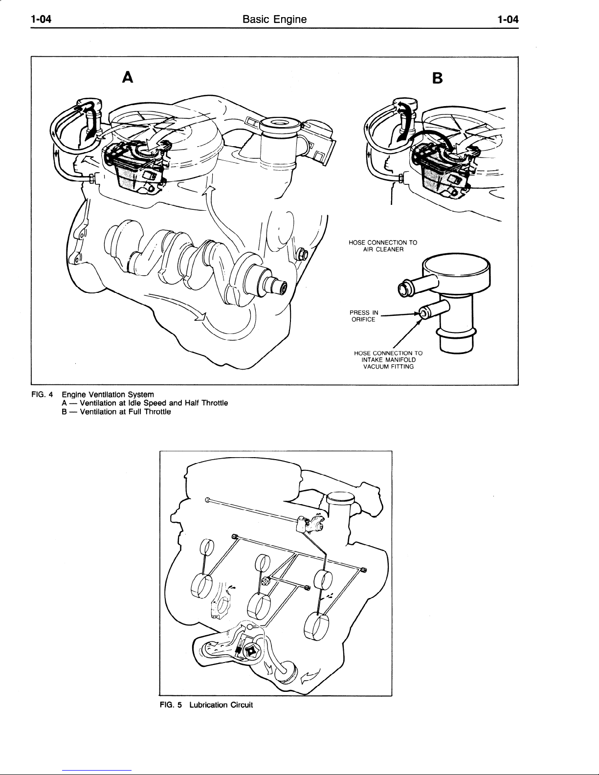
Engine Ventilation, Figure 4.
The ventilation system consists of an oil filler cap with two
connecting hoses, one of which passes to the inlet manifold and
the other to the air cleaner.
The result is a closed ventilation system in which the fumes
from the crankcase pass back via the inlet manifold into the
cylinders for combustion.
Gas flow is regulated by a calibrated orifice in the oil filler cap.
Lubrication circuit, Figure 5.
An eccentric twin-rotor oil pump draws oil via a strainer from
the sump and forces it into the full-flow oil filter.
Oil pressure is regulated by a relief valve inside the pump. The
filtered oil passes through the center of the filter element, then
along a short passage (right hand side of the engine) to the oil
pressure switch and through a transverse bore to the main oil
gallery (left hand side of the engine).
The crankshaft main bearings are fed directly from the main oil
gallery and the camshaft bearings are linked, in turn for their
lubrication with the front, center and rear main bearings. Each of
the rod journals are supplied with oil by the nearest main bearing
through oblique passages.
An oil hole in the connecting rod ensures splash lubrication of
the piston pins and the trailing side of the cylinders. Timing chain
and sprockets are also lubricated via a splash hole. The camshaft
front bearing journal has a machined groove through which oil is
intermittently forced to the rocker shaft (via passages in cylinder
block and cylinder head).
l-03
Basic Engine
I-03
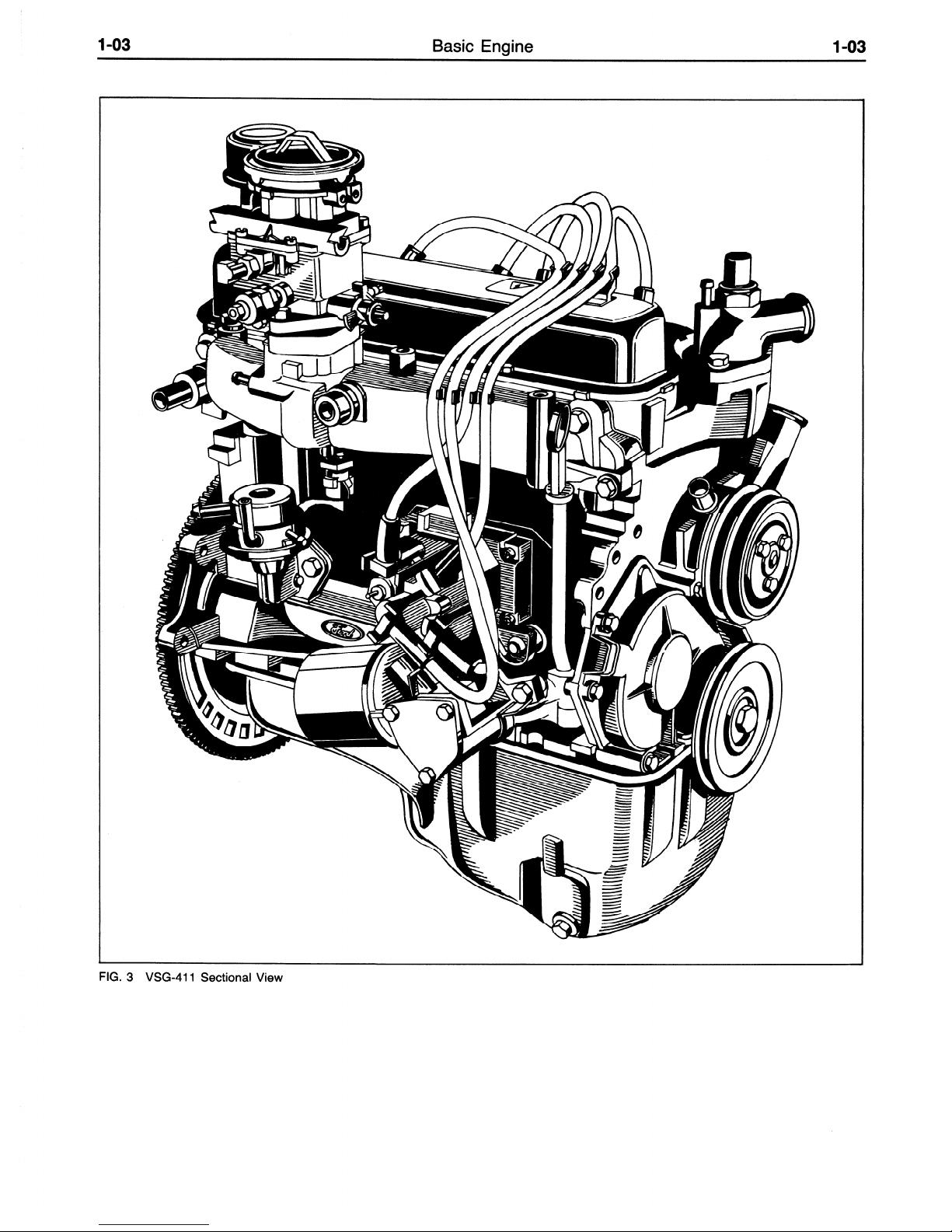
FIG. 3 VSG-411 Sectional View
l-04
Basic Engine
HOSE CONNECTION TO
AIR CLEANER
PRESS IN
ORIFICE
HOSE CX
INNECTION TO
INTAKE MANIFOLD
VACUUM FITTING
FIG. 4 Engine Ventilation System
A - Ventilation at Idle Speed and Half Throttle
B- Ventilation at Full Throttle
FIG. 5 Lubrication Circuit

l-05
Basic Engine
l-05
DIAGNOSIS AND TESTING
CAMSHAFT LOBE LIFT
Check the lift of each lobe in consecutive order and make a note
of the readings.
1. Remove the air cleaner and the valve rocker arm cover.
2. Remove the valve rocker arm shaft assembly as detailed in the
pertinent section.
3. Make sure the push rod is in the valve lifter socket. Install a
dial indicator in such a manner as to have the ball socket
adapter of the indicator on the end of the push rod and in the
same plane as the push rod movement (Figure 6).
FIG. 6 Testing Camshaft Lobe Lift
4. Connect an auxiliary starter switch in the starting circuit.
Crank the engine with the ignition switch OFF. Bump the
crankshaft over until the tappet or lifter is on the base circle of
the camshaft lobe. At this point, the push rod will be in its
lowest position.
5. Zero the ‘dial indicator. Continue to rotate the crankshaft
slowly until the push rod is in the fully raised position (highest
indicator reading).
6. Compare the total lift recorded on the indicator with
specifications.
7. To check the accuracy of the original indicator reading, continue to rotate the crankshaft until the indicator reads zero.
If
the lift on any lobe is below specified wear limits, the
camshaft and the valve lifters operating on the worn
lobe(s) must be replaced.
8. Remove the dial indicator and auxiliary starter switch.
9. Install the rocker arm shaft assembly as detailed under Removal and Installation.
10. Install the valve rocker arm cover and the air cleaner.
COMPRESSION TEST
COMPRESSION GAUGE CHECK
1.
Be sure the crankcase is at the proper level and the battery is
properly charged. Operate the engine for a minimum of 30
minutes at 1200 rpm or until the engine is at normal operating
temperature. Turn the ignition switch off; then remove all the
spark plugs.
2. Set the carburetor throttle plates and chc~ke plate in the wide
open position.
3. Install a compression gauge in No. 1 cylinder.
4. Install an auxiliary starter switch in the starting circuit. Using
the auxiliary starter switch, crank the engine (with the ignition
switch off) at least five compression strokes and record the
highest reading.
Note the approximate number of compression strokes required
d
to obtain the highest reading.
5.
Repeat the test on each cylinder as was required to obtain the
highest reading on the No. 1 cylinder.
TEST CONCLUSION
The indicated compression pressures are considered normal if
the lowest reading cylinder is within 75% of the highest. Refer to
the following example and Figure 7.
Seventy-five percent of 140, the highest cylinder reading, is
105. Therefore, cylinder No. 7 being less than 75% of cylinder
No. 3 indicates an improperly seated valve or worn or broken
piston rings.
If one or more cylinders read low, squirt approximately one (1)
tablespoon of engine oil on top of the pistons in the low reading
cylinders. Repeat compression pressure check on these cylinders.
1. If compresison improves considerably, the piston rings are at
fault.
2. If compression does not improve, valves are sticking or seating poorly.
3. If two adjacent cylinders indicate low compression pressures
’ and squirting oil on the pistons does not increase the compres-
sion, the cause may be a cylinder head gasket leak between the
cylinders. Engine oil and/or coolant in the cylinders could
result from this problem.
It is recommended the following quick reference chart be used
when checking cylinder compression pressures. The chart has
been calculated so that the lowest reading number is 75% of the
highest reading.
EXAMPLE
After checking the compression pressures in all cylinders, it was
found that the highest reading obtained was 196 psi. The lowest
pressure reading was 155 psi. The engine is within specifications
and the compression is considered satisfactory.
CRANKSHAFT END PLAY
1. Force the crankshaft toward the rear of the engine.
2. Install a dial indicator so that the contact point rests against the
crankshaft flange and the indicator axis is parallel to the
crankshaft axis .
3. Zero the dial indicator. Push the crankshaft forward and note
the reading on the dial.
4. If the end play exceeds the wear limit, replace the thrust
washers. If the end play is less than the minimum limit,
inspect the thrust bearing faces for scratches, burrs, nicks, or
dirt.
FLYWHEEL FACE RUNOUT
Install a dial indicator so that the indicator point bears against
the flywheel face. Turn the flywheel, making sure that it is full
forward or rearward so that the crankshaft end play will not be
indicated as flywheel runout.
If the clutch face runout exceeds specifications, remove the
flywheel and check for burrs between the flywheel and the face of
the crankshaft mounting flange. If no burrs exist, check the runout
of the crankshaft mounting flange. Replace the flywheel, or machine the crankshaft-flywheel mounting face sufficiently to true up
the surface if the mounting flange runout exceeds spec”fications.
Replace it or reinstall it on the flywheel.
CAMSHAFT END PLAY
Push the camshaft toward the rear of the engine. Install a dial
indicator so that the indicator point is on the camshaft sprocket
attaching screw or gear hub. Zero the dial indicator. Position a
large screwdriver between the camshaft sprocket and the cylinder
head. Pull the camshaft forward and release it. Compare the dial
indicator reading with specifications. If the end play is excessive,
replace the thrust plate retaining the camshaft. Remove the dial
indicator.

l-06
Basic Engine
I-06
Maximum
PSI
I
Minimum
PSI
~~~ T
Maximum
PSI
134
101
174
131
136
102
176
132
138
104 178 133
140
105 180 135
142
107
182
136
144
108
184 138
146 110
186 140
148 111
188
141
150 113
190
142
152 114
192 144
154
115
194 145
156
117
196
147
158 118 198 148
160 120
200 150
162
121
202 151
164 123 204 153
166
124
206
154
168 126 208 156
170
127
210
157
172 129 212 158
Minimum
PSI
I
Maximum
PSI
214
216
218
220
222
224
226
228
230
232
234
236
238
240
242
244
246
248
250
Minimum
PSI
160
162
163
165
166
168
169
171
172
174
175
177
178
180
181
183
184
186
187
FIG. 7 Quick Reference Compression Pressure Limit Chart
CA1
005-A
OVERHAUL
CYLINDER HEAD
Replace the head if it is cracked.
Do not plane or grind more
than 0.010 inch from the cylinder head gasket surface.
Remove
all burrs or scratches with an oil stone.
REAMING VALVE GUIDES
If it becomes necessary to ream the valve guide (Figure 8)) to an
oversize valve always use the reamer in sequence.
Always reface
the valve seat after the valve guide has been reamed, and use a
suitable scraper to break the sharp corner (ID) at the top of the
valve guide.
BREAKSHARP
FIG. 8
Reaming Valve Guides
REFACING VALVE SEATS
Refacing of the valve seat should be closely coordinated with
the refacing of the valve face so that the finished seat and valve
face will be concentric and the specified interference fit will be
maintained. This is important so that the valve and seat will have a
compression-tight fit. Be sure that the refacer grinding wheels are
properly dressed.
Grind the valve seats to a true 45 degree angle (Figure 9).
Remove only enough stock to clean up pits and grooves or to
correct the valve seat runout. After the seat has been refaced, use a
seat width scale or a machinist scale to measure the seat width
(Figure 10). Narrow the seat, if necessary, to bring it within
snecifications.
TO REMOVE STOCK FROM TO REMOVE STOCK FROM
TOP OF SEAT
I
BOTTOM OF SEAT
USE 30” WHEEL
I
USE 60” WHEEL
A7382-1 A
FIG. 9 Refacing
Valve
Seat
If the valve seat width exceeds the maximum limit, remove
enough stock from the top edge and/or bottom edge of the seat to
reduce the width to specifications.
On the
valve seats
of all
engines,
use a 60 degree angle grinding
wheel
to remove stock from the
bottom of the seats (raise the seats)
and use a 30 degree angle
wheel
to remove stock from the top of
the seats (lower
the seats).
The finished valve seat should
contact the approximate center
of the valve face. It is good practice to determine where the valve

l-07
Basic Engine
l-07
seat contacts the face. To do this, coat the seat with Prussian blue
and set the valve in place. Rotate the valve with light pressure. If
the blue is transferred to the center of the valve face, the contact is
satisfactory. If the blue is transferred to the top edge of the valve
face, lower the valve seat. If the blue is transferred to the bottom
edge of the valve face, raise the valve seat.
SEAT WIDTH SCALE
A
FOR DIMENSIONS
CHECK FOR
REFER TO
BENT STEM
SPECIFICATIONS
<
DIAMETER
VALVE
VALVE FACE MARGIN
FACE ANGLE
l/32” MINIMUM
(EDGE OF VALVE HEAD)
THIS LINE PARALLEL
WITH VALVE HEAD
I
AlOOSO-1B
Minor pits, grooves, etc.,
may be removed. Discard valves that
are severely damaged, if the face runout cannot be corrected by
refinishing or stem clearance exceeds specifications. Discard
any
excessively worn or damaged valve train parts.
REFACING VALVES
The valve refacing operation should be closely coordinated
with the valve seat refacing operations so that the finished angles
of the valve face and of the valve seat will be to specifications and
provide a compression-tight fit. Be sure that the refacer grinding
wheels are properly dressed.
Under no circumstances should the faces of aluminized intake
valves be ground or the valves lapped in as this will remove the
diffused aluminum coating and reduce the valves’ wear and heat
resistant properties. If the valve faces are worn or pitted it will be
necessary to install new valves and to resurface the valve seats or,
alternatively, lap the seats using dummy valves. The exhaust
valves may be lapped in or the faces ground if required.
If the valve face runout is excessive and/or to remove pits and
grooves, reface the valves to a true 44 degree angle. Remove only
enough stock to correct the runout or to clean up the pits and
grooves. If the edge of the valve head is less than l/32 inch thick
after grinding (Figure 1 l), replace the valve as the valve will run
too hot in the engine.
The interference fit of the valve and seat
should not be lapped out. Remove all grooves or score marks
from the end of the valve stem, and chamfer it as necessary.
Do not remove more than 0.010 inch from the end of the valve
stem.
If the valve and/or valve seat has been refaced, it will be
necessary to check the clearance between the rocker arm pad and
the valve stem with the valve train assembly installed in the
engine.
SELECT FllTlNG VALVES
If the valve stem to valve guide clearance exceeds the wear
limit, ream the valve guide for the
next
oversize valve stem.
Valves with oversize stem diameter ar’e available for service.
Always reface the valve seat after the guide has been reamed.
Refer to Reaming Valve Guides.
FIG. 11 Critical Valve Dimensions
CAMSHAFT REPAIR
Remove light scuffs, scores or nicks from the camshaft ma-
chined surfaces with a smooth oil stone.
CRANKSHAFT
Dress minor scores with an oil stone. If the journals are severely
marred or exceed the wear limit, they should be refinished to size
for the next undersize bearing.
REFINISHING JOURNALS
Refinish the journals to give the proper clearance with the next
undersize bearing. If the journal will not clean up to maximum
undersize bearing available, replace the crankshaft.
Always reproduce the same journal shoulder radius that existed
originally. Too small a radius will result in fatigue failure of the
crankshaft. Too large a radius will result in bearing failure due to
radius ride of the bearing.
After refinishing the journals, chamfer the oil holes; then polish
the journal with a No. 320 grit polishing cloth and engine oil.
Crocus cloth may also be used as a polishing agent.
FITTING MAIN OR CONNECTING ROD BEARINGS
WITH PLASTIGAGE
1. Clean crankshaft journals. Inspect journals and thrust faces
(thrust bearing) for nicks, burrs or bearing pickup that would
cause premature bearing wear.
When replacing standard
bearings with new bearings, it is good practice to fit the
bearing to minimum specified clearance.
If the desired
clearance cannot be obtained with a standard bearing, try a
0.002 inch undersize in combination with a standard bearing
to obtain the proper clearance.
2. If fitting a main bearing in the chassis,
position a jack under
the counterweight adjoining bearing which is being
checked. Support crankshaft with jack so its weight will
not compress Plastigage and provide an erroneous
reading.

Basic Engine
3. Place a piece of Plastigage on bearing surface across full
width of bearing cap and about l/4 inch off center (Figure 12).
4. Install cap and torque bolts to specifications. Do not turn
crankshaft while Plastigage is in place.
5. Remove cap. Using Plastigage scale, check width of Plastigage at widest point to get minimum clearance. Check at
narrowest point to get maximum clearance. Difference between readings is taper of journals.
6. If clearance exceeds specified limits on the connecting rod
bearings, try a 0.002 inch undersize bearing in combination
with the standard bearings. Bearing clearance must be within
specified limits. If 0.002 undersize main bearings are used on
more than one journal, be sure they are all installed in cylinder
block side of bearing. If standard and 0.002 inch undersize
bearings do not bring clearance within desired limits, refinish
crankshaft journal, then install undersize bearings.
7. After bearing has been fitted, remove Plastigage, apply light
coat of engine oil to journal and bearings. Install bearing cap.
Torque cap bolts to specifications.
8. Repeat procedure for remaining bearings that require
replacement.
PLACE PLASTIGAGE
FULL WIDTH
OF JOURNAL ABOUT
l/4
INCH OFF CENTER
2. Select the proper size piston to provide the desired clearance
(refer to the specifications). The piston should be measured
2-l/4 inches below the dome and at 90’ to the piston pin bore.
3. Make sure the piston and cylinder block are at room temperature (70 degrees F.).
After any refinishing operation
allow the cylinder bore to cool, and make sure the piston
and bore are clean and dry before the piston fit is checked.
FITTING PISTON RINGS
Three piston rings are fitted, two compression and one oil
control ring.
1. Select the proper ring set for the size cylinder bore.
2. Position the ring in the cylinder bore in which it is going to be
used.
3. Push the ring down into the bore area where normal ring wear
is not encountered.
4. Use the head of a piston to position the ring in the bore so that
the ring is square with the cylinder wall.
Use caution to avoid
damage to the ring or cylinder bore.
5. Measure the gap between the ends of the ring with a feeler
gauge (Figure 13). If the ring gap is less or greater than the
specified limits, try another ring set.
P
IN
PLASTIGAGE
FIG. 12 Installing and Measuring Plastigage
\ -1
. I
-CHECK WIDTH
1 CLEARANCE
OF PLASTIGAGE
A2868-B
PISTONS, PINS AND RINGS
FITTING PISTONS
Pistons are available for service in standard sizes and the over-
sizes shown in the parts list.
Measure the piston diameter to ensure that the specified clearance is obtained. It may be necessary periodically to use another
piston that is either slightly larger or smaller to achieve the specified clearance.
provide the proper clearance for the piston. When a piston has
been fitted, mark it for assembly in the cylinder to which it was
fitted. If the taper, out-of-round and piston to cylinder bore
clearance conditions of the cylinder bore are within specified
limits, new piston rings will give satisfactory service. If new
rings are to be installed in a used cylinder that has not been
refinished, remove the cylinder wall glaze (Refer to Cylinder
Block, Refinishing Cylinder Walls). Be sure to clean the cylinder bore thoroughly.
1. Calculate the size piston to be used by taking a cylinder bore
check. Follow the procedures outlined under Cleaning and
Inspection.
If none can be fitted, refinish the cylinder to
FIG. 13 Checking Piston Ring Gap
6. Check the ring side clearance of the compression rings with a
feeler gauge inserted between the ring and its lower land
(Figure 14). The gauge should slide freely around the entire
ring circumference without binding. Any wear that occurs will
form a step at the inner portion of the lower land.
If the lower
lands have high steps, the piston should be replaced.
FIG. 14 Checking Piston Ring Side Clearance

l-09
Basic Engine
l-09
FllTlNG PISTON PINS
The piston pins are selected to give the correct fit in the piston
pin bore and bushing in the connecting rod. Pistons are only
supplied in service complete with the piston pin, to ensure the
correct fit. The piston pins should not be interchanged.
VALVE ROCKER ARM AND/OR SHAFT
ASSEMBLY
Dress up minor surface defects on the rocker arm shaft and in the
rocker arm bore with a hone.
If the pad at the valve end of the rocker arm has a grooved
radius, replace the rocker
arm. Do not attempt to true this
surface by grinding.
PUSH RODS
Following the procedures under Push Rod Inspection, check the
push rods for straightness.
If the runout exceeds the maximum limit at any point, discard
the rod.
Do not attempt to straighten push rods.
CYLINDER BLOCK
REFINISHING CYLINDER WALLS
Honing is recommended for refinishing cylinder walls
only
when the walls have minor scuffs or scratches, or for fitting pistons
to the specified clearance. The grade of hone to be used is determined by the amount of metal to be removed. Follow the instructions of the hone manufacturer. If coarse stones are used to start the
honing operation, leave enough material so that all hone marks can
be removed with the finishing hone which is used to obtain the
proper piston clearance. Cylinder walls that are severely marred
and/or worn beyond the specified limits should be refinished.
Before any cylinder is refinished, all main bearing caps must
be in place and tightened to the proper torque so that the
crankshaft bearing bores will not become distorted from the
refinishing operation.
Refinish only the cylinder or cylinders that
require it. All pistons are the same weight, both standard and
oversize; therefore, various sizes of pistons can be used without
upsetting engine balance. Refinish the cylinder with the most wear
first to determine the maximum oversize. If the cylinder will not
clean up when refinished for the maximum oversize pistonrecommended, replace the block. Refinish the cylinder to within approximately 0.0015 inch of the required oversize diameter. This will
allow enough stock for the final step of honing so that the correct
surface finish and pattern are obtained. For the proper use of the
refinishing equipment follow the instructions of the manufacturer.
Only experienced personnel should be allowed to perform this
work. Use a motor-driven, spring pressure-type hone at a speed of
300500 rpm. Hones of grit sizes 180-220 will normally provide
the desired bore surface finish of 15/32 RMS. When honing the
cylinder bores use a lubricant mixture of equal parts of kerosene
and SAE No. 20 motor oil. Operate the hone in such a way to
produce a cross-hatch finish on the cylinder bore. The cross-hatch
pattern should be at an angle of approximately 30 degrees to the
cylinder bore. After the final operation in either of the two refinishing methods described and prior to checking the piston fit,
thoroughly clean and oil the cylinder walls. Mark the pistons to
correspond to the cylinders in which they are to be installed. When
the refinishing of all cylinders that require it has been completed
and all pistons are fitted, thoroughly clean the entire block and oil
the cylinder walls.
REPAIRING SAND HOLES OR
POROUS ENGINE CASTINGS
Porosity or sand hole(s) which will cause oil seepage or leakage
can occur with modem casting processes. A complete inspection
of engine and transmission should be made. If the leak is attributed
to the porous condition of the cylinder block or sand hole(s),
repairs can be made with metallic plastic (part No. C6AZ- 19554A).
Do not repair cracks with this material.
Repairs with this
metallic plastic must be confined to those cast iron engine component surfaces where the inner wall surface is not exposed to engine
coolant pressure or oil pressure. For example:
1. Cylinder block surfaces extending along the length of the
block, upward from the oil pan rail to the cylinder water jacket
but not including machined areas.
2. Lower rear face of the cylinder block.
3. Intake manifold casting.
4. Cylinder head, along the rocker arm cover gasket surface.
The following procedure should be used to repair porous areas
or sand holes in cast iron.
a.
Clean the surface to be repaired by grinding or rotary filing
to a clean bright metal surface. Chamfer or undercut the
hole or porosity to a greater depth than the rest of the
cleaned surface. Solid metal must surround the hole.
Openings larger than l/4 inch should not be repaired using
metallic plastic. Openings in excess of l/4 inch can be
drilled, tapped and plugged using common tools. Clean
the repair area thoroughly. Metallic plastic will not stick to
a dirty or oily surface.
b. Mix the metallic plastic base and hardener as directed on
the container. Stir thoroughly until uniform.
c.
Apply the repair mixture with a suitable clean tool, (putty
knife, wood spoon, etc.) forcing the epoxy into the hole or
porosity.
d. Allow the repair mixture to harden. This can be accom-
plished by two methods, heat cure with a 250 degree lamp
placed 10 inches from the repaired surface, or air dry for
lo- 12 hours at temperatures above 50 degrees F.
e. Sand or grind the repaired area to blend with the general
contour of the surrounding surface.
f. Paint the surface to match the rest of the block.

l-10
Basic Engine
CLEANING AND INSPECTION
The cleaning and inspection procedures are for a complete
engine overhaul; therefore, for partial engine overhaul or parts
replacement, follow the pertinent cleaning or inspection
procedure.
INTAKE MANIFOLD
Cleaning
Remove all gasket material from the machined surfaces of the
manifold. Clean the manifold in a suitable solvent and dry it with
compressed air.
l-10
CYLINDER HEADS
Cleanlng
With the valves installed to protect the valve seats, remove
deposits from the combustion chambers and valve heads with
a scraper and a wire brush. Be careful not to damage the
cylinder head gasket surface.
clean the valve guide bores with a valve guide cleaning tool. Use
cleaning solvent to remove dirt, grease and other deposits. Clean
all bolt holes. Remove all deposits from the valves with a fine wire
brush or buffing wheel.
After the valves are removed,
Inspection
Inspect the manifold for cracks, damaged gasket surfaces, or
other defects that would make it unfit for further service. Replace
all studs that are stripped or otherwise damaged.
Remove all
filings and foreign matter that may have entered the manifold
as a result of repairs.
EXHAUST MANIFOLDS
Cleaning
Remove all gasket material from the manifolds.
Inspection
Inspect the cylinder head joining flanges of the exhaust mani-
fold for evidence of exhaust gas leaks.
Inspect the manifolds for cracks, damaged gasket surfaces, or
other defects that would make them unfit for further service.
VALVE ROCKER ARM AND/OR SHAFT
ASSEMBLY
Cleaning
Clean all the parts thoroughly. Make sure all oil passages are
open.
Make sure the oil passage in the rocker arm is open.
Inspection
On rocker arm shaft assemblies, check the clearance between
each rocker arm and the shaft by checking the ID of the rocker arm
bore and the OD of the shaft. If the clearance between any rocker
arm and the shaft exceeds the wear limit, replace the shaft and/or
the rocker arm. Inspect the shaft and the rocker arm bore for nicks,
scratches, scores or scuffs.
Inspect the pad at the valve end of the rocker arm for indications
of scuffing or abnormal wear. If the pad is grooved, replace the
rocker arm.
Check the adjusting nut(s) torque. If not within specifications,
replace the nut(s). Check the rocker arm pad and fulcrum seat for
excessive wear, cracks, nicks or burrs.
Do not attempt to true this surface by grinding.
Inspection
Check the cylinder head for cracks and inspect the gasket
surface for burrs and nicks. Replace the head if it is cracked.
The following inspection procedures are for a cylinder head that
is to be completely overhauled. For individual repair operations,
use
only the pertinent inspection procedure.
When a cylinder head is removed because of gasket leaks,
check the flatness of the cylinder head gasket surface (Figure 15)
for conformance to specifications. If necessary to refinish the
cylinder head gasket surface,
than 0.010 inch.
I
I
FIG.
@@CHECK DIAGONALLY
@CHECK ACROSS CENTER
15
Typical Cylinder Head Flatness
Check the valve seat runout with an accurate gauge (Figure 16).
Follow the instructions of the gauge manufacturer. If the runout
exceeds the wear limit, reface the valve and valve seat. Measure
the valve seat width (Figure 10). Reface any valve seat whose
width
is not within specifications.
RUNOUT GAUGE
do not plane or grind off more
A2895 1 C
PUSH RODS
Cleaning
Clean the push rods in a suitable solvent. Blow dry the pushrod
with compressed air.
Inspection
Check the ends of the push rods for nicks, grooves, roughness
or excessive wear.
The push rods can be visually checked for straightness while
they are installed in the engine by rotating them with the valve
closed. They also can be checked with a dial indicator.
If the push rod is visibly bent, it should be replaced.
A9624-1 A
FIG. 16 Checking Valve Seat Runout
l-11
Basic Engine
l-11
Inspect the valve face and the edge of the valve head for pits,
grooves, scores or other damage. Inspect the stem for a bent
condition and the end of the valve head for pits, grooves, scores
or other wear. Inspect the stem for a bent condition and the end
of the stem for grooves or scores. Check the valve head for
signs of burning, erosion, warpage and cracking. Minor pits,
grooves, etc., may be removed. Discard valves that are severely
damaged.
Inspect the valve spring, valve spring retainers, locks and
sleeves for wear or damage. Discard any visually damaged parts.
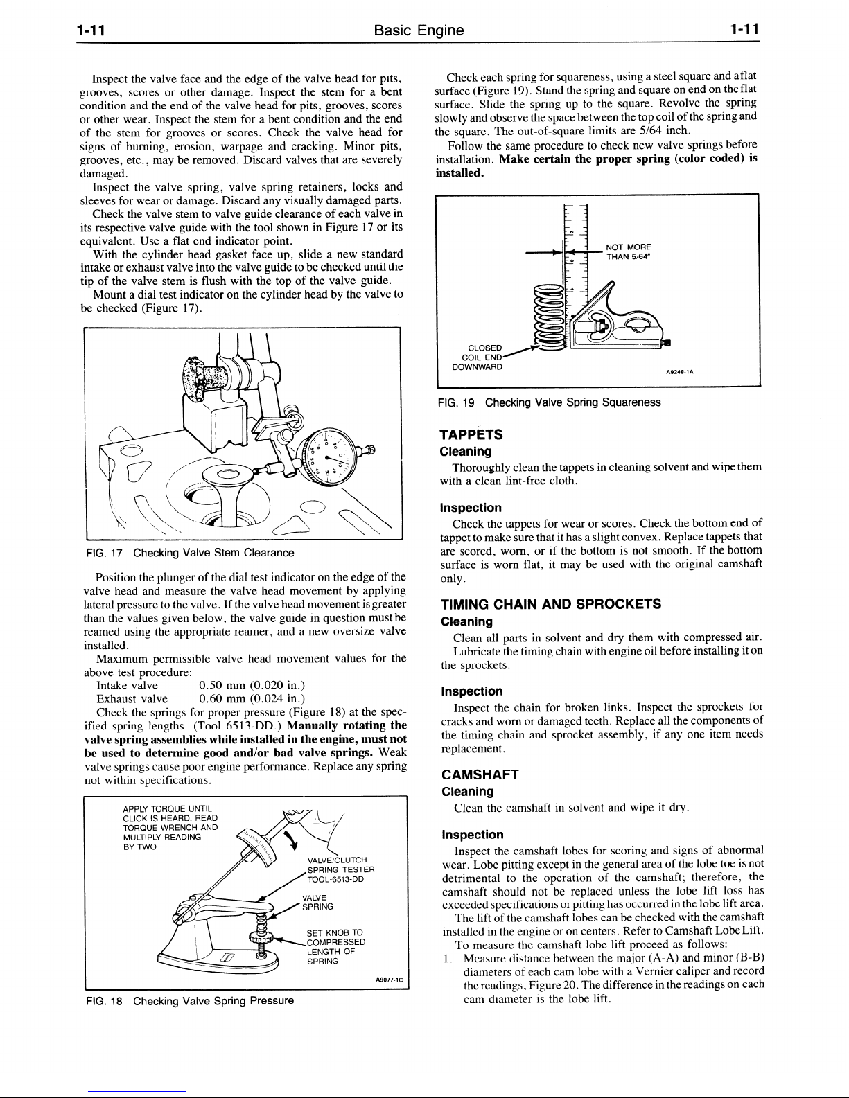
Check the valve stem to valve guide clearance of each valve in
its respective valve guide with the tool shown in Figure 17 or its
equivalent. Use a flat end indicator point.
With the cylinder head gasket face up, slide a new standard
intake or exhaust valve into the valve guide to be checked until the
tip of the valve stem is flush with the top of the valve guide.
Mount a dial test indicator on the cylinder head by the valve to
be checked (Figure 17).
FIG. 17 Checking Valve Stem Clearance
Position the plunger of the dial test indicator on the edge of the
valve head and measure the valve head movement by applying
lateral pressure to the valve. If the valve head movement is greater
than the values given below, the valve guide in question must be
reamed using the appropriate reamer, and a new oversize valve
installed.
Maximum permissible valve head movement values for the
above test procedure:
Intake valve
0.50 mm (0.020 in.)
Exhaust valve
0.60
mm (0.024 in.)
Check the springs for proper pressure (Figure 18) at the spec-
ified spring lengths. (Tool 65 13-DD.)
Manually rotating the
valve spring assemblies while installed in the engine, must not
be used to determine good and/or bad valve springs.
Weak
valve springs cause poor engine performance. Replace any spring
not within specifications.
APPLY TORQUE UNTIL
CLICK IS HEARD, READ
TORQUE WRENCH AND
MULTIPLY READING
BY TWO
SPRING TESTE
TOOL-6513-DD
SET KNOB TO
COMPRESSED
A9077-1C
FIG. 18 Checking Valve Spring Pressure
Check each spring for squareness, using a steel square and aflat
surface (Figure 19). Stand the spring and square on end on the flat
surface. Slide the spring up to the square. Revolve the spring
slowly and observe the space between the top coil of the spring and
the square. The out-of-square limits are 5/64 inch.
Follow the same procedure to check new valve springs before
installation.
Make certain the proper spring (color coded) is
installed.
CLOSED
COIL END
DOWNWARD
A9248-1 A
Thoroughly clean the tappets in cleaning solvent and wipe them
with a clean lint-free cloth.
Inspection
Check the tappets for wear or scores. Check the bottom end of
tappet to make sure that it has a slight convex. Replace tappets that
are scored, worn, or if the bottom is not smooth. If the bottom
surface is worn flat, it may be used with the original camshaft
only.
TIMING CHAIN AND SPROCKETS
Cleaning
Clean all parts in solvent and dry them with compressed air.
Lubricate the timing chain with engine oil before installing it on
the sprockets.
Inspection
Inspect the chain for broken links. Inspect the sprockets for
cracks and worn or damaged teeth. Replace all the components of
the timing chain and sprocket assembly, if any one item needs
replacement.
CAMSHAFT
Cleaning
Clean the camshaft in solvent and wipe it dry.
Inspection
Inspect the camshaft lobes for scoring and signs of abnormal
wear. Lobe pitting except in the general area of the lobe toe is not
detrimental to the operation of the camshaft; therefore, the
camshaft should not be replaced unless the lobe lift loss has
exceeded specifications or pitting has occurred in the lobe lift area.
The lift of the camshaft lobes can be checked with the camshaft
installed in the engine or on centers. Refer to Camshaft Lobe Lift.
To measure the camshaft lobe lift proceed as follows:
1. Measure distance between the major (A-A) and minor (B-B)
diameters of each cam lobe with a Vernier caliper and record
the readings, Figure 20. The difference in the readings on each
cam diameter is the lobe lift.

Basic Engine
l-12
NO PITTING
ALLOWED IN
THIS AREA
DIMENSION A MINUS
DIMENSIO
N B EQUALS
LOBE LIFT
A64898
FIG.
l/4”
l/4”
t J
A
20
Camshaft Lobe Lift Measurement Camshaft Removed
2. If the readings do not meet specification, replace the
camshaft.
CAMSHAFT BORES
Inspection
Check camshaft bores for size, taper, roundness, runout, and
finish. If any of these dimensions exceeds the limits given in
Specifications, install new camshaft bearings.
CRANKSHAFT
Cleaning
Handle the crankshaft with care to avoid possible fractures or
damage to the finished surfaces. Clean the crankshaft with solvent, then blow out all oil passages with compressed air.
Inspection
Inspect the main and connecting rod journals for cracks,
scratches, grooves or scores. Inspect the crankshaft oil seal surface
for nicks, sharp edges or burrs that might damage the oil seal
during installation or cause premature seal wear.
Measure the diameter of each journal in at least four places to
determine an out-of-round, taper or undersize condition (Figure
21).
AVSB=
CVSD= HORIZONTAL TAPER
A
CHECK FOR OUT-OF-ROUND AT EACH END OF JOURNAL
VS C AND
VERTICAL TAPER
B VS D
= OUT OF ROUND
FLYWHEEL
Inspection
Inspect the flywheel for cracks, heat check, or other damage
that would make it unfit for further service. Machine the friction
surface of the flywheel if it is scored or worn. If it is necessary to
remove more than 0.045 inch of stock from the original thickness,
replace the flywheel.
Inspect the ring gear for worn, chipped, or cracked teeth. If the
teeth are damaged, replace the ring gear.
With the flywheel installed on the crankshaft, check the
flywheel face runout, following the procedure under Diagnosis
and Testing.
CONNECTING RODS
Cleaning
Removing the bearings from the rod and cap. Identify the
bearings if they are to be used again. Clean the connecting rod in
solvent, including the rod bore and the back of the inserts.
use a caustic cleaning solution.
Blow out all passages with
Do not
compressed air.
Inspection
The connecting rods and related parts should be carefully in-
spected and checked for conformance to specifications. Various
forms of engine wear caused by these parts can be readily
identified.
A shiny surface on either pin boss side of the piston usually
indicates that a connecting rod is bent.
Abnormal connecting rod bearing wear can be caused by either
a bent connecting rod, worn or damaged crankpin, or a tapered
connecting rod bore.
Twisted connecting rods will not create an identifiable wear
pattern, but badly twisted rods will disturb the action of the entire
piston, rings and connecting rod assembly and may be the cause of
excessive oil consumption.
Inspect the connecting rods for signs of fractures and the bearing
bores for out-of-round and taper. If the bore exceeds the recommended limits and/or if the connecting rod is fractured, it should
be replaced. Check the ID of the connecting rod piston pin bore. If
the pin bore in the connecting rod is larger than specifications,
install a 0.002 inch oversize piston pin. First, prefit the oversize
piston pin to the piston pin bore by reaming or honing the piston.
Then, assemble the piston, piston pin and connecting rod follow-
ing the procedures for assembly.
It is not necessary to ream or
hone the pin bore in the connecting rod. Replace damaged
connecting rod nuts and bolts. Check the connecting rods for
bend or twist on a suitable alignment fixture. Follow the
instructions of the fixture manufacturer. If the bend and/or
twist exceeds specifications, the connecting rod must be
straightened or replaced.
PISTONS, PINS AND RINGS
Cleaning
Remove deposits from the piston surfaces. Clean gum or var-
nish from the piston skirt, piston pins and rings with solvent.
not use a caustic cleaning solution or a wire brush to clean
pistons.
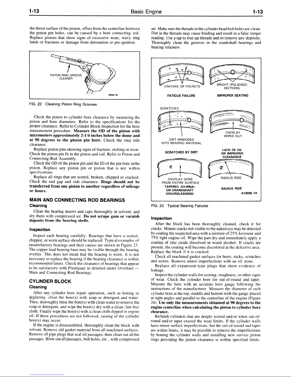
Clean the ring grooves with a ring groove cleaner (Figure 22).
Make sure the oil ring slots (or holes) are clean.
Do
FIG. 21 Crankshaft Journal Measurement
A2901-1B
Inspection
Carefully inspect the pistons for fractures at the ring lands,
skirts and pin bosses, and for scuffed, rough or scored skirts. If the
lower inner portion of the ring grooves has a high step, replacethe
piston. The step will interfere with ring operation and
excessive ring side clearance.
Spongy, eroded areas near the edge of the top of the piston are
usually caused by detonation or pre-ignition. A shiny surface on
cause
Basic Engine
1-13
the thrust surface of the piston, offset from the centerline between
the piston pin holes, can be caused by a bent connecting rod.
Replace pistons that show signs of excessive wear, wavy ring
lands or fractures or damage from detonation or pre-ignition.
air. Make sure the threads in the cylinder head bolt holes are clean.
Dirt in the threads may cause binding and result in a false torque
reading. Use a tap to true up threads and to remove any deposits.
Thoroughly clean the grooves in the crankshaft bearings and
bearing retainers.
CLEANER
FIG. 22 Cleaning Piston Ring Grooves
Check the piston to cylinder bore clearance by measuring the
piston and bore diameters. Refer to the specifications for the
proper clearance. Refer to Cylinder Block Inspection for the bore
measurement procedure.
Measure the OD of the piston with
micrometers approximately 2-I/4 inches below the dome and
at 90 degrees to the piston pin bore.
Check the ring side
clearance.
Replace piston pins showing signs of fracture, etching or wear.
Check the piston pin fit in the piston and rod. Refer to Piston and
Connecting Rod Assembly.
Check the OD of the piston pin and the ID of the pin bore inthe
piston. Replace any piston pin or piston that is not within
specifications.
Replace all rings that are scored, broken, chipped or cracked.
Check the end gap and side clearance.
Rings should not be
transferred from one piston to another regardless of mileage
or hours.
MAIN AND CONNECTING ROD BEARINGS
Cleaning
Clean the bearing inserts and caps thoroughly in solvent, and
dry them with compressed air.
Do not scrape gum or varnish
deposits from the bearing shells.
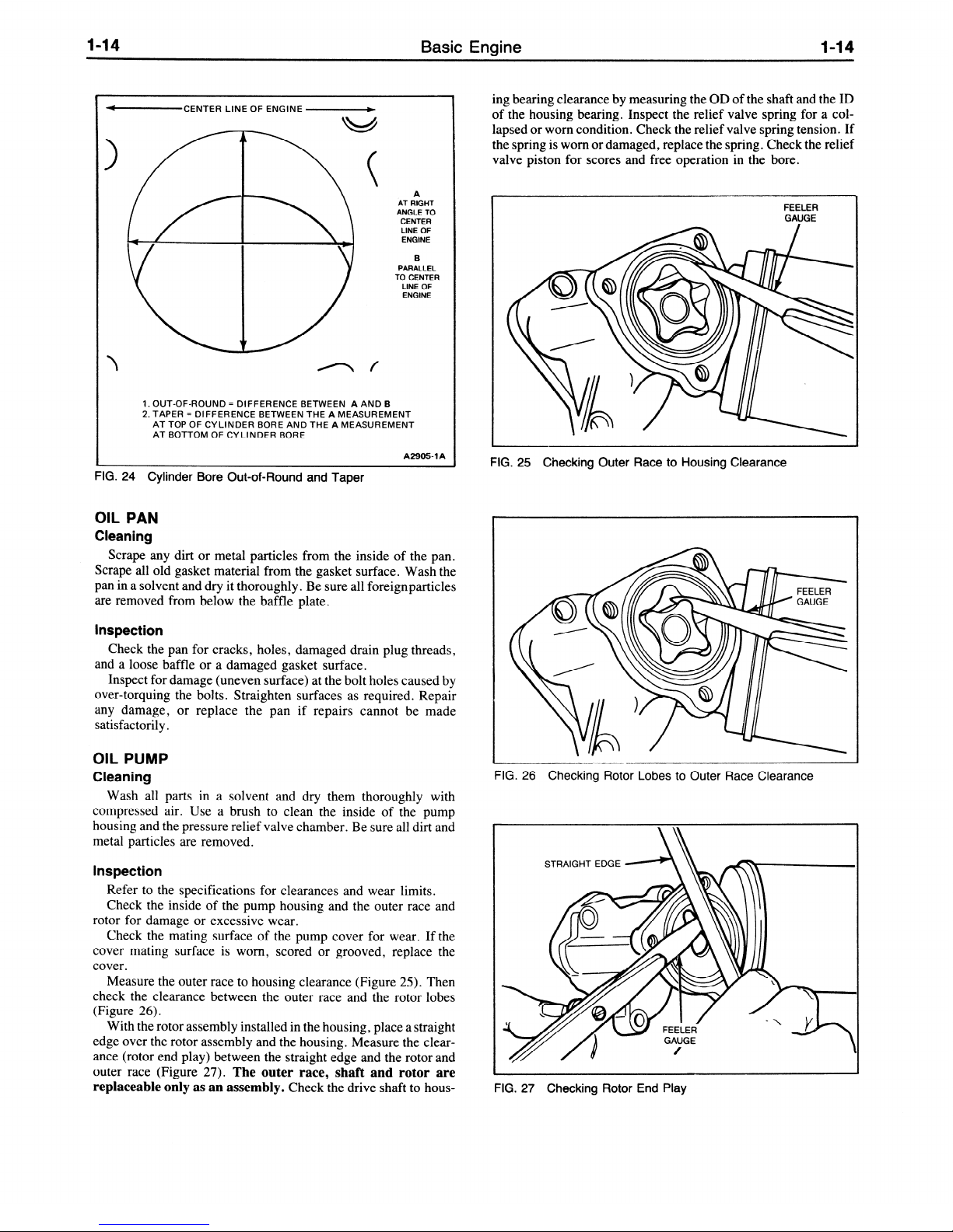
Inspection
Inspect each bearing carefully. Bearings that have a scored,
chipped, or worn surface should be replaced. Typical examples of
unsatisfactory bearings and their causes are shown in Figure 23.
The copper lead bearing base may be visible through the bearing
overlay. This does not mean that the bearing is worn. It is not
necessary to replace the bearing if the bearing clearance is within
recommended limits. Check the clearance of bearings that appear
to be satisfactory with Plastigage as detailed under Overhaul Main and Connecting Rod Bearings.
CYLINDER BLOCK
Cleaning
After any cylinder bore repair operation, such as honing or
deglazing, clean the bore(s) with soap or detergent and water.
Then, thoroughly rinse the bore(s) with clean water to remove the
soap or detergent, and wipe the bore(s) dry with a clean, lint-free
cloth. Finally wipe the bore(s) with a clean cloth dipped in engine
oil. If these procedures are not followed, rusting of the cylinder
bore(s) may occur.
If the engine is disassembled, thoroughly clean the block with
solvent. Remove old gasket material from all machined surfaces.
Remove all pipe plugs that seal oil passages; then clean out all the
passages. Blow out all passages, bolt holes, etc. , with compressed
CRATERS OR
POCKETS
FATIGUE FAILURE
IMPROPER SEATING
SCRATCHES
WIPED OUT
DIRT IMBEDDED
INTO BEARING MATERIAL
SCRATCHED BY DIRT
LACK OF OIL
OR IMPROPER
CLEARANCE
ww
OVERLAY GONE
FROM ENTIRE SURFACE
TAPERED JOURNAL
OR CRANKSHAFT
(HOURGLASSING)
RADIUS RIDE
A10095-1A
FIG. 23 Typical Bearing Failures
Inspection
After the block has been thoroughly cleaned, check it for
cracks. Minute cracks not visible to the naked eye
may
be detected
by coating the suspected area with a mixture of 25% kerosene and
75% light engine oil. Wipe the part dry and immediately apply a
coating of zinc oxide dissolved in wood alcohol. If cracks are
present, the coating will become discolored at the defective area.
Replace the block if it is cracked.
Check all machined gasket surfaces for burrs, nicks, scratches
and scores. Remove minor imperfections with an oil stone.
Replace all expansion-type plugs that show evidence of
leakage a
Inspect the cylinder walls for scoring, roughness, or other signs
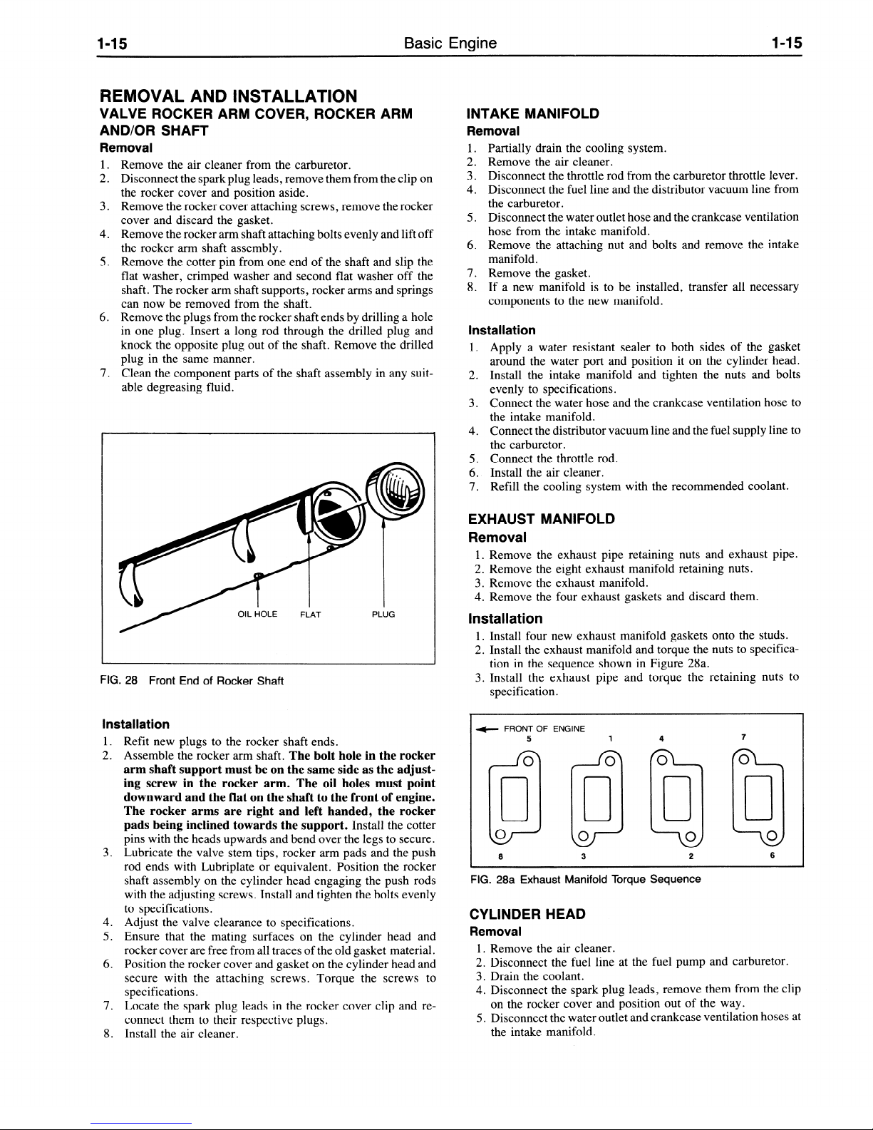
of wear. Check the cylinder bore for out-of-round and taper.
Measure the bore with an accurate bore gauge following the
instructions of the manufacturer. Measure the diameter of each
cylinder bore at the top, middle and bottom with the gauge placed
at right angles and parallel to the centerline of the engine (Figure
24). Use only the measurements obtained at 90 degrees to the
engine centerline when calculating the piston to cylinder bore
clearance.
Refinish cylinders that are deeply scored and/or when out-ofround and/or taper exceed the wear limits. If the cylinder walls
have minor surface imperfections, but the out-of-round and taper
are within limits, it may be possible to remove the imperfections
by honing the cylinder walls and installing new service piston
rings providing the piston clearance is within specified limits.
Basic Engine
l-14
-CENTER LINE OF ENGINE -
\
n f
A
AT RIGHT
ANGLE
TO
CENTER
LINE OF
ENGINE
B
PARALLEL
TO CENTER
LINE OF
ENGINE
1. OUT-OF-ROUND = DIFFERENCE BETWEEN A AND B
2. TAPER = DIFFERENCE BETWEEN THE A MEASUREMENT
AT TOP OF CYLINDER BORE AND THE A MEASUREMENT
AT BOTTOM OF CYLINDER BORE
A29051 A
FIG. 24
Cylinder Bore Out-of-Round and Taper
OIL PAN
Cleaning
Scrape any dirt or metal particles from the inside of the pan.
Scrape all old gasket material from the gasket surface. Wash the
pan in a solvent and dry it thoroughly. Be sure all foreignparticles
are removed from below the baffle plate.
Inspection
Check the pan for cracks, holes, damaged drain plug threads,
and a loose baffle or a damaged gasket surface.
Inspect for damage (uneven surface) at the bolt holes caused by
over-torquing the bolts . Straighten surfaces as required. Repair
any damage, or replace the pan if repairs cannot be made
satisfactorily.
OIL PUMP
Cleaning
Wash all parts in a solvent and dry them thoroughly with
compressed air. Use a brush to clean the inside of the pump
housing and the pressure relief valve chamber. Be sure all dirt and
metal particles are removed.
Inspection
Refer to the specifications for clearances and wear limits.
Check the inside of the pump housing and the outer race and
rotor for damage or excessive wear.
Check the mating surface of the pump cover for wear. If the
cover mating surface is worn, scored or grooved, replace the
cover.
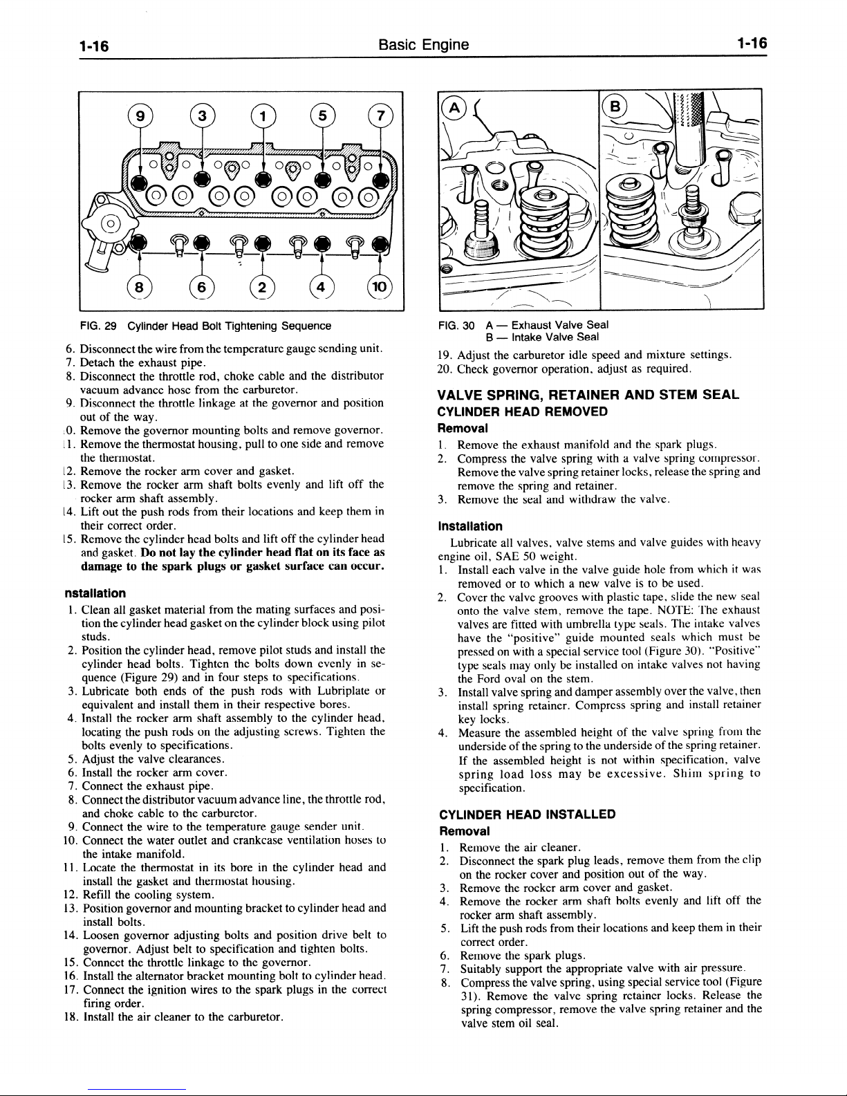
Measure the outer race to housing clearance (Figure 25). Then
check the clearance between the outer race and the rotor lobes
(Figure 26).
With the rotor assembly installed in the housing, place a straight
edge over the rotor assembly and the housing. Measure the clearance (rotor end play) between the straight edge and the rotor and
outer race (Figure 27).
The outer race, shaft and rotor are
replaceable only as an assembly.
Check the drive shaft to hous-
ing bearing clearance by measuring the OD of the shaft and the ID
of the housing bearing. Inspect the relief valve spring for a col-
lapsed or worn condition. Check the relief valve spring tension. If
the spring is worn or damaged, replace the spring. Check the relief
valve piston for scores and free operation in the bore.
FEELER
GAUGE
FIG. 25 Checking Outer Race to Housing Clearance
FIG. 26 Checking Rotor Lobes to Outer Race Clearance
STRAIGHT EDGE
FIG. 27 Checking Rotor End Play

l-15
Basic Engine
REMOVAL AND INSTALLATION
VALVE ROCKER ARM COVER, ROCKER ARM
AND/OR SHAFT
Removal
1. Remove the air cleaner from the carburetor.
2. Disconnect the spark plug leads, remove them from the clip on
the rocker cover and position aside.
3. Remove the rocker cover attaching screws, remove the rocker
cover and discard the gasket.
4. Remove the rocker arm shaft attaching bolts evenly and lift off
the rocker arm shaft assembly.
5. Remove the cotter pin from one end of the shaft and slip the
flat washer, crimped washer and second flat washer off the
shaft. The rocker arm shaft supports, rocker arms and springs
can now be removed from the shaft.
6. Remove the plugs from the rocker shaft ends by drilling a hole
in one plug. Insert a long rod through the drilled plug and
knock the opposite plug out of the shaft. Remove the drilled
plug in the same manner.
7. Clean the component parts of the shaft assembly in any suit-
able degreasing fluid.
l-15
INTAKE MANIFOLD
Removal
1. Partially drain the cooling system.
2. Remove the air cleaner.
3. Disconnect the throttle rod from the carburetor throttle lever.
4. Disconnect the fuel line and the distributor vacuum line from
the carburetor.
5. Disconnect the water outlet hose and the crankcase ventilation
hose from the intake manifold.
6. Remove the attaching nut and bolts and remove the intake
manifold.
7. Remove the gasket.
8. If a new manifold is to be installed, transfer all necessary
components to the new manifold.
Installation
1. Apply a water resistant sealer to both sides of the gasket
around the water port and position it on the cylinder head.
2. Install the intake manifold and tighten the nuts and bolts
evenly to specifications.
3. Connect the water hose and the crankcase ventilation hose to
the intake manifold.
4. Connect the distributor vacuum line and the fuel supply line to
the carburetor.
5. Connect the throttle rod.
6. Install the air cleaner.
7. Refill the cooling system with the recommended coolant.
FIG. 28
Installation
1.
2.
3.
4.
5.
6.
7.
8.
Front End of Rocker Shaft
Refit new plugs to the rocker shaft ends.
Assemble the rocker arm shaft.
arm shaft support must be on the same side as the adjusting screw in the rocker arm. The oil holes must point
downward and the flat on the shaft to the front of engine.
The rocker arms are right and left handed, the rocker
pads being inclined towards the support.
pins with the heads upwards and bend over the legs to secure.
Lubricate the valve stem tips, rocker arm pads and the push
rod ends with Lubriplate or equivalent. Position the rocker
shaft assembly on the cylinder head engaging the push rods
with the adjusting screws. Install and tighten the bolts evenly
to specifications.
Adjust the valve clearance to specifications.
Ensure that the mating surfaces on the cylinder head and
rocker cover are free from all traces of the old gasket material.
Position the rocker cover and gasket on the cylinder head and
secure with the attaching screws. Torque the screws to
specifications.
Locate the spark plug leads in the rocker cover clip and reconnect them to their respective plugs.
Install the air cleaner.
The bolt hole in the rocker
Install the cotter
EXHAUST MANIFOLD
Removal
1. Remove the exhaust pipe retaining nuts and exhaust
2. Remove the eight exhaust manifold retaining nuts.
3. Remove the exhaust manifold.
4. Remove the four exhaust gaskets and discard them.
Installation
1. Install four new exhaust manifold gaskets onto the studs.
2. Install the exhaust manifold and torque the nuts to specification in the sequence shown in Figure 28a.
3. Install the exhaust pipe and torque the retaining nuts to
specification.
L
e FRONT OF ENGINE
L
FIG. 28a Exhaust Manifold Torque Sequence
CYLINDER HEAD
Removal
1. Remove the air cleaner.
2. Disconnect the fuel line at the fuel pump and carburetor.
3. Drain the coolant.
4. Disconnect the spark plug leads, remove them from the clip
5. Disconnect the water outlet and crankcase ventilation hoses at
5
0
cl
0
0
8
on the rocker cover and position out of the way.
the intake manifold.
1 4
0
cl
0
0
3
0
cl
0
0
2
pipe.
7
0
cl
0
0
6
l-15
Basic Engine
REMOVAL AND INSTALLATION
VALVE ROCKER ARM COVER, ROCKER ARM
AND/OR SHAFT
Removal
1. Remove the air cleaner from the carburetor.
2. Disconnect the spark plug leads, remove them from the clip on
the rocker cover and position aside.
3. Remove the rocker cover attaching screws, remove the rocker
cover and discard the gasket.
4. Remove the rocker arm shaft attaching bolts evenly and lift off
the rocker arm shaft assembly.
5. Remove the cotter pin from one end of the shaft and slip the
flat washer, crimped washer and second flat washer off the
shaft. The rocker arm shaft supports, rocker arms and springs
can now be removed from the shaft.
6. Remove the plugs from the rocker shaft ends by drilling a hole
in one plug. Insert a long rod through the drilled plug and
knock the opposite plug out of the shaft. Remove the drilled
plug in the same manner.
7. Clean the component parts of the shaft assembly in any suit-
able degreasing fluid.
l-15
INTAKE MANIFOLD
Removal
1. Partially drain the cooling system.
2. Remove the air cleaner.
3. Disconnect the throttle rod from the carburetor throttle lever.
4. Disconnect the fuel line and the distributor vacuum line from
the carburetor.
5. Disconnect the water outlet hose and the crankcase ventilation
hose from the intake manifold.
6. Remove the attaching nut and bolts and remove the intake
manifold.
7. Remove the gasket.
8. If a new manifold is to be installed, transfer all necessary
components to the new manifold.
Installation
1. Apply a water resistant sealer to both sides of the gasket
around the water port and position it on the cylinder head.
2. Install the intake manifold and tighten the nuts and bolts
evenly to specifications.
3. Connect the water hose and the crankcase ventilation hose to
the intake manifold.
4. Connect the distributor vacuum line and the fuel supply line to
the carburetor.
5. Connect the throttle rod.
6. Install the air cleaner.
7. Refill the cooling system with the recommended coolant.
FIG. 28
Installation
1.
2.
3.
4.
5.
6.
7.
8.
Front End of Rocker Shaft
Refit new plugs to the rocker shaft ends.
Assemble the rocker arm shaft.
arm shaft support must be on the same side as the adjusting screw in the rocker arm. The oil holes must point
downward and the flat on the shaft to the front of engine.
The rocker arms are right and left handed, the rocker
pads being inclined towards the support.
pins with the heads upwards and bend over the legs to secure.
Lubricate the valve stem tips, rocker arm pads and the push
rod ends with Lubriplate or equivalent. Position the rocker
shaft assembly on the cylinder head engaging the push rods
with the adjusting screws. Install and tighten the bolts evenly
to specifications.
Adjust the valve clearance to specifications.
Ensure that the mating surfaces on the cylinder head and
rocker cover are free from all traces of the old gasket material.
Position the rocker cover and gasket on the cylinder head and
secure with the attaching screws. Torque the screws to
specifications.
Locate the spark plug leads in the rocker cover clip and reconnect them to their respective plugs.
Install the air cleaner.
The bolt hole in the rocker
Install the cotter
EXHAUST MANIFOLD
Removal
1. Remove the exhaust pipe retaining nuts and exhaust
2. Remove the eight exhaust manifold retaining nuts.
3. Remove the exhaust manifold.
4. Remove the four exhaust gaskets and discard them.
Installation
1. Install four new exhaust manifold gaskets onto the studs.
2. Install the exhaust manifold and torque the nuts to specification in the sequence shown in Figure 28a.
3. Install the exhaust pipe and torque the retaining nuts to
specification.
L
e FRONT OF ENGINE
L
FIG. 28a Exhaust Manifold Torque Sequence
CYLINDER HEAD
Removal
1. Remove the air cleaner.
2. Disconnect the fuel line at the fuel pump and carburetor.
3. Drain the coolant.
4. Disconnect the spark plug leads, remove them from the clip
5. Disconnect the water outlet and crankcase ventilation hoses at
5
0
cl
0
0
8
on the rocker cover and position out of the way.
the intake manifold.
1 4
0
cl
0
0
3
0
cl
0
0
2
pipe.
7
0
cl
0
0
6
l-16
Basic Engine
l-16
FIG. 29 Cylinder Head Bolt Tightening Sequence
6. Disconnect the wire from the temperature gauge sending unit.
7. Detach the exhaust pipe.
8. Disconnect the throttle rod, choke cable and the distributor
vacuum advance hose from the carburetor.
9. Disconnect the throttle linkage at the governor and position
out of the way.
kO. Remove the governor mounting bolts and remove governor.
Il. Remove the thermostat housing, pull to one side and remove
the thermostat.
12. Remove the rocker arm cover and gasket.
13. Remove the rocker arm shaft bolts evenly and lift off the
rocker arm shaft assembly.
14. Lift out the push rods from their locations and keep them in
their correct order.
15. Remove the cylinder head bolts and lift off the cylinder head
and gasket.
damage to the spark plugs or gasket surface can occur.
Do not lay the cylinder head flat on its face as
nstallation
1. Clean all gasket material from the mating surfaces and position the cylinder head gasket on the cylinder block using pilot
studs.
2. Position the cylinder head, remove pilot studs and install the
cylinder head bolts. Tighten the bolts down evenly in sequence (Figure 29) and in four steps to specifications.
3. Lubricate both ends of the push rods with Lubriplate or
equivalent and install them in their respective bores.
4. Install the rocker arm shaft assembly to the cylinder head,
locating the push rods on the adjusting screws. Tighten the
bolts evenly to specifications.
5. Adjust the valve clearances.
6, Install the rocker arm cover.
7. Connect the exhaust pipe.
8. Connect the distributor vacuum advance line, the throttle rod,
and choke cable to the carburetor.
9. Connect the wire to the temperature gauge sender unit.
10. Connect the water outlet and crankcase ventilation hoses to
the intake manifold.
11. Locate the thermostat in its bore in the cylinder head and
install the gasket and thermostat housing.
12. Refill the cooling system.
13. Position governor and mounting bracket to cylinder head and
install bolts.
14. Loosen governor adjusting bolts and position drive belt to
governor. Adjust belt to specification and tighten bolts.
15. Connect the throttle linkage to the governor.
16. Install the alternator bracket mounting bolt to cylinder head.
17. Connect the ignition wires to the spark plugs in the correct
firing order.
18. Install the air cleaner to the carburetor.
FIG. 30 A -
19. Adjust the carburetor idle speed and mixture settings.
20. Check governor operation, adjust as required.
Exhaust Valve Seal
Intake Valve Seal
B-
VALVE SPRING, RETAINER AND STEM SEAL
CYLINDER HEAD REMOVED
Removal
1. Remove the exhaust manifold and the spark plugs.
2. Compress the valve spring with a valve spring compressor.
Remove the valve spring retainer locks, release the spring and
remove the spring and retainer.
3. Remove the seal and withdraw the valve.
Installation
Lubricate all valves, valve stems and valve guides with heavy
engine oil, SAE 50 weight.
1. Install each valve in the valve guide hole from which it was
removed or to which a new valve is to be used.
2. Cover the valve grooves with plastic tape, slide the new seal
onto the valve stem, remove the tape. NOTE: The exhaust
valves are fitted with umbrella type seals. The intake valves
have the “positive” guide mounted seals which must be
pressed on with a special service tool (Figure 30). “Positive”
type seals may only be installed on intake valves not having
the Ford oval on the stem.
3. Install valve spring and damper assembly over the valve, then
install spring retainer. Compress spring and install retainer
key locks.
4. Measure the assembled height of the valve spring from the
underside of the spring to the underside of the spring retainer.
If the assembled height is not within specification, valve
spring load loss may be excessive. Shim spring to
specification.
CYLINDER HEAD INSTALLED
Removal
1. Remove the air cleaner.
2. Disconnect the spark plug leads, remove them from the clip
on the rocker cover and position out of the way.
3. Remove the rocker arm cover and gasket.
4. Remove the rocker arm shaft bolts evenly and lift off the
rocker arm shaft assembly.
5. Lift the push rods from their locations and keep them in their
correct order.
6. Remove the spark plugs.
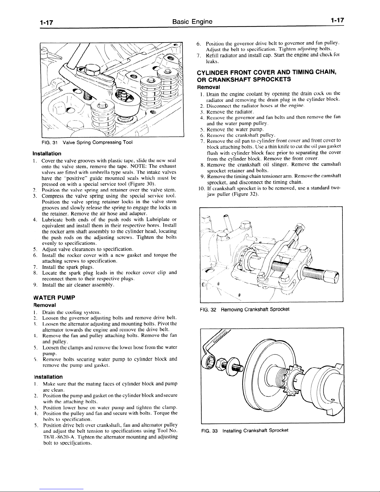
7. Suitably support the appropriate valve with air pressure.
8. Compress the valve spring, using special service tool (Figure
3 1). Remove the valve spring retainer locks. Release the
spring compressor, remove the valve spring retainer and the
valve stem oil seal.
l-17
Basic Engine
l-17
FIG. 31 Valve Spring Compressing Tool
Installation
1.
Cover the valve grooves with plastic tape, slide the new seal
onto the valve stem, remove the tape. NOTE: The exhaust
valves are fitted with umbrella type seals. The intake valves
have the “positive” guide mounted seals which must be
pressed on with a special service tool (Figure 30).
Position the valve spring and retainer over the valve stem.
Compress the valve spring using the special service tool.
Position the valve spring retainer locks in the valve stem
grooves and slowly release the spring to engage the locks in
the retainer. Remove the air hose and adapter.
Lubricate both ends of the push rods with Lubriplate or
equivalent and install them in their respective bores. Install
the rocker arm shaft assembly to the cylinder head, locating
the push rods on the adjusting screws. Tighten the bolts
evenly to specifications.
Adjust valve clearances to specification.
Install the rocker cover with a new gasket and torque the
attaching screws to specification.
Install the spark plugs.
Locate the spark plug leads in the rocker cover clip and
reconnect them to their respective plugs.
Install the air cleaner assembly.
2.
3.
4.
5.
6.
7.
8.
9.
WATER PUMP
Removal
1. Drain the cooling system.
2. Loosen the governor adjusting bolt,s and remove drive belt.
3. Loosen the alternator adjusting and mounting bolts. Pivot the
alternator towards the engine and remove the drive belt.
4. Remove the fan and pulley attaching bolts. Remove the fan
and pulley. .
5. Loosen the clamps and remove the lower hose from the water
Pump*
5. Remove bolts securing water pump to cylinder block and
remove the pump and gasket.
Installation
1. Make sure that the mating faces of cylinder block and pump
are clean.
2. Position the pump and gasket on the cylinder block andsecure
with the attaching bolts.
3. Position lower hose on water pump and tighten the clamp.
4. Position the pulley and fan and secure with bolts. Torque the
bolts to specification.
5. Position drive belt over crankshaft, fan and alternator pulley
and adjust the belt tension to specifications using Tool No.
T63L-8620-A. Tighten the alternator mounting and adjusting
bolt to specifications.
6. Position the governor drive belt to governor and fan pulley.
Adjust the belt to specification. Tighten adjusting bolts.
7.
Refill radiator and install cap. Start the engine and check for
leaks.
CYLINDER FRONT COVER AND TIMING CHAIN,
OR CRANKSHAFT SPROCKETS
Removal
1. Drain the engine coolant by opening the drain cock on the
radiator and removing the drain plug in the cylinder block.
2. Disconnect the radiator hoses at the engine.
3. Remove the radiator.
4. Remove the governor and fan belts and then remove the fan
and the water pump pulley.
5. Remove the water pump.
6. Remove the crankshaft pulley.
7. Remove the oil pan to cylinder front cover and front cover to
block attaching bolts. Use a thin knife to cut the oil pan gasket
flush with cylinder block face prior to separating the cover
from the cylinder block. Remove the front cover.
8. Remove the crankshaft oil slinger. Remove the camshaft
sprocket retainer and bolts.
9. Remove the timing chain tensioner arm. Remove the camshaft
sprocket, and disconnect the timing chain.
10. If crankshaft sprocket is to be removed, use a standard twojaw puller (Figure 32).
FIG. 32 Removing Crankshaft Sprocket
FIG. 33 Installing Crankshaft Sprocket

l-18
Basic Engine
l-18
FIG. 34 Timing Marks
FIG. 35 Aligning Front Cover and Seal
Installation
1 + If crankshaft sprocket was removed, install using the pulley,
bolt and washer. The timing mark on the sprocket must face
the end of the crankshaft.
2. Position the timing chain over the camshaft and crankshaft
sprockets so that the timing marks are aligned when the
sprocket is installed (Figure 34).
on top dead center when using the gear marks as reference.
Tighten the bolts to specification, then bend up the
locking tabs.
3. Locate the tensioner arm on the pivot pin while holding the
tensioner cam in the released position.
4. Install the oil slinger on the crankshaft.
5. Position the gasket, portions of oil pan gasket, if necessary,
and the end seal on the front cover with an oil resistant sealer at
the ends. Install the front cover and align the seal by installing
the crankshaft pulley (Figure 35). Tighten the attaching bolts
evenly to specification.
6. Install and torque crankshaft pulley retaining bolt.
7. Install the water pump and torque the attaching bolts to
specification.
8. Install the water pump pulley and fan. Install the governor and
fan belts and adjust the tension of the belts to specifications
using Tool T63L-8620-A.
9. Install the radiator.
10. Install the radiator upper and lower hoses and tighten the
clamps.
11. Refill the radiator.
12. Start engine and check for oil and water leaks.
The number 4 cylinder is
FIG. 36 Removing Front Cover Oil Seal
FIG. 37 Front Oil Seal Installation
A - Seal
C - Crankshaft Pulley
B - Tool 21-046
ADJUSTING VALVE CLEARANCES
1. Only turn the crankshaft belt pulley clockwise while adjusting
the valve clearances and start by aligning the mark on the belt
pulley with the “0” mark on the front cover.
2. If belt pulley is now turned to and fro slightly, valves of
cylinder No. 1 or 4 will be rocking, i.e., the two rockers and
push rods move in opposite directions.
3. When valves in cylinder No. 4 are rocking, No. 1 cylinder
valve clearances should be adjusted.
4. Then rotate belt pulley a further half turn. In this position
valves of cylinder No. 3 will rock and valve clearances of
cylinder No. 2 can be adjusted and so on according to firing
order. (See Technical Data for settings. )
Cylinder No. 4 rocking - adjust cylinder No. 1
Cylinder No. 3 rocking - adjust cylinder No. 2
Cylinder No. 1 rocking - adjust cylinder No. 4
Cylinder No. 2 rocking - adjust cylinder No. 3
CRANKSHAFT FRONT OIL SEAL
Removal
1. Loosen alternator and adjusting bracket bolts and remove fan
belt.
2. Remove crankshaft pulley bolt and remove pulley by hand.
3. Remove oil seal from front cover using special service tool
(21-096). NOTE: Use short end of tool on this seal (Figure
36).

l-19
Basic Engine
l-19
Installation
1. Lubricate the sealing lip of the new seal with engine oil and
push new seal into front cover using tool 21-046, crankshaft
pulley, bolt and washer (Figure 37).
2. Remove special service tool and reinstall crankshaft pulley.
Torque bolt to specification.
3. Install fan belt and adjust the tension of the belts to specification using Tool T63L-8620-A. Tighten alternator and adjusting bracket bolts.
CAMSHAFT AND/OR VALVE LIFTERS
Removal
1. Remove the engine assembly and mount the engine on a
stand. Drain the crankcase.
2.
Disconnect the fuel line at the fuel pump.
3. Loosen the alternator and governor adjustment bolts and remove the belts.
4. Remove the fan and water pump pulley.
5. Remove the oil and fuel pumps from the cylinder block.
6. Disconnect the spark plug wires from the plugs and remove
the distributor from the cylinder block.
7. Remove the rocker arm cover attaching screws and rocker
cover Clean all gasket material from rocker arm cover and
cylinder head.
8. Remove the rocker arm shaft support bolts evenly and lift off
the rocker arm shaft.
9. Lift the push rods from their locations in the cylinder block,
taking care to keep them in their correct order.
10. Invert the engine on the stand and remove the oil pan and
gaskets.
11. Remove the crankshaft pulley, the front cover and oil slinger.
12. Remove the timing chain tensioner assembly.
13. Remove the camshaft sprocket and timing chain.
14. With the engine inverted, remove the camshaft thrust plate
and remove the camshaft (Figure 38).
15. If necessary, remove the tappets from their locations in the
cylinder block and keep them in the correct order.
FIG. 38 Camshaft Removal
Installation
1. Install a new front cover oil seal, using Tool 21-046.
2. Install the tappets, if removed.
3. Install the camshaft and fit the thrust plate in the camshaft
groove. Tighten the attaching bolts to specification and bend
up the locking tabs
4. Check the camshaft end play.
5. Locate the timing chain on the camshaft sprocket and install
the camshaft sprocket with the timing mark aligned with the
one on the crankshaft sprocket. Tighten the attaching bolts to
specification and bend up the locking tabs.
6. Locate the tensioner arm on the pivot pin and install the timing
chain tensioner.
11. Install the crankshaft pulley aligning the pulley slot with the
7. Install the oil slinger on the crankshaft.
crankshaft key. Tighten the pulley attaching bolt to
8. Position the gasket on the front cover with an oil resistant
sealer at the ends, align the front cover with the crankshaft
specification.
pulley and tighten the bolts evenly to specification.
9. Position a new gasket on the block flange using an oil resistant
sealer compound at each end. Position the end seals chamfered ends into the groove, again using an oil resistant sealer at
the ends and install the oil pan. Tighten the oil pan bolts to the
correct torque, FOLLOWING FIRST THE ALPHABETICAL, THEN THE NUMERICAL SEQUENCES
SHOWN IN Figure 39.
10. Install the dipstick.
14 13 12 11
10 9 8
0
0
0
0
0
u
L
17 ‘B
K J H
G F
E
D O16
\3
M
N 0 P
Q
R
-
0
o- 0, 0
0
1
2 3 4 5
6
7
FIG. 39 Oil Pan Bolt Tightening Sequence
12. Right the engine on stand. Install and time the distributor.
13. Position a new gasket on the oil pump mounting flange and
install the oil pump and filter assembly. Tighten the attaching
bolts to specification.
14. Position a new gasket to the fuel pump flange and insert the
rocker arm through the slot in the block wall so that the arm
lies on the camshaft eccentric. Secure the fuel pump to the
cylinder block with two washers and bolts, tightening the
bolts evenly to specifications.
15. Lubricate push rod ends, valve stem tips and rocker pads with
Lubriplate or equivalent. Install the push rods in their respective bores and install the rocker arm shaft assembly, making
sure that the cupped ends of the push rods engage the adjusting
screws. Tighten the rocker arm shaft attaching bolts evenly to
specification.
16. Adjust the valve clearances to specification.
17. Install the rocker arm cover and a new gasket and secure with
attaching screws and torque to specifications.
18. Install the distributor and connect the vacuum advance line to
the carburetor o
19. Install distributor cap and connect wires to spark plugs.
20. Install the water pump pulley and fan. Position the alternator
and governor drive belts on the pulley and adjust the belt
tension to specifications. Connect the fuel line from the carburetor to the fuel pump.
21. Remove engine from stand.
22. Install the engine assembly in the unit.
23. Start the engine and check for oil and water leaks.
24. Install the air cleaner assembly.
25. Start engine, adjust the ignition timing, if necessary.

l-2
Basic Engine
l-20
26. Adjust the carburetor idle speed and fuel-air mixture to specifications. Check governor operation.
CAMSHAFT BEARINGS
The service bearings for the camshaft are pre-sized and require
no machining after installation. When one bearing requires replacement it is advisable to replace all three, as camshaft alignment may be affected if only one bearing is changed.
The camshaft front and rear bearings are both approximately
31’4 inch wide, the front one having an additional oil hole for the
rocker arm shaft oil feed, and the center bearing approximately 5/8
inch wide. Install the bearings using a replacer in addition to the
adapters previously used. Make sure that the oil holes in the
bearings and cylinder block are correctly aligned before installation and that the splits in the bearings are upwards and outwardsat
45 degrees to the vertical.
Removal
Remove camshaft following the appropriate procedures in this
section.
1. Remove the flywheel.
2. Remove the crankshaft rear oil seal carrier.
3. Remove the camshaft bearings.
4.
Check all the oil passages to make sure that they are clear.
Apply an oil resistant sealer to the oil gallery plugs prior to
installation.
Installation
1.
Install new camshaft bearings. Make sure that the oil holes in
the bearings and cylinder block are aligned. The splits in the
bearings should be upwards and outwards at 45 degrees to the
vertical (Figure 40).
2.
Install a new crankshaft rear oil seal using Tool 2 1-059A.
3. Position a new gasket to the rear oil seal carrier using an oil
resistant sealer at the ends. Install the carrier on the cylinder
block and tighten the bolts evenly to specification.
4. Locate the flywheel squarely on the crankshaft flange. Tighten the attaching bolts to specification.
5.
Install the camshaft and related parts following the appropriate procedures in this section.
CAMSHAFT BEARING
A3375-A
FIG. 40 Camshaft Bearing Position
OIL PUMP
The oil pump and filter assembly is bolted to the right side of the
cylinder block and can be removed with the engine in place.
Removal
1. Place a drain pan under the oil pump.
2. Remove the oil filter from the oil pump.
3. Remove the three bolts attaching the oil pump and remove the
assembly.
Installation
1 6 Ensure the mating surfaces are clean of old gasket material,
then install the oil pump assembly on the cylinder block, using
a new gasket together with an oil resistant sealer and secure
with the three bolts. Tighten the bolts to specifications.
2.
Install the oil filter to the oil pump assembly.
3.
Check the oil level and add oil if necessary.
4. Start the engine and check for oil leaks.
OIL PAN
Removal
1. Drain the crankcase.
2. Remove the oil level dipstick.
3.
Remove the three bolts and remove the starter motor.
4. Remove the oil pan attaching bolts and remove the pan and
gasket.
Installation
1. Clean the ail pump inlet tube and screen assembly.
3
I.
Clean the gasket surfaces of the block and oil pan. Be sure
to
clean the seal retainer grooves in the cylinder front cover and
the rear seal retainer. The oil pan has a two-piece gasket. Coat
the block surface and the oil pan gasket surface with oilresistant sealer. Position the oil pan gaskets on the cylinder
block.
3. Position the end seals with the chamfered ends into the
grooves, again using an oil resistant sealer. Position the oil
pan and tighten the bolts evenly to specifications following
first the alphabetical, then the numerical sequences shown in
Figure 39.
4. Clean and install the starter motor, securing it with the three
bolts.
5. Refill the oil pan with the correct grade of engine oil and install
the dipstick.
6.
Start the engine and check for oil leaks.
FLYWHEEL RING GEAR
The flywheel ring gear is located in a retention groove and can
be removed by cutting between two adjacent teeth with a hacksaw
and splitting the gear with a chisel. In no circumstances should
pressure be applied in an attempt to remove the ring gear for
repositioning on the flywheel.
When installing the ring gear it must be heated evenly to a
temperature of 260 to 280°C (500-535°F). Do not exceed 290°C
(554°F) as the ring gear wear resistant properties will be destroyed.
If the ring gear is to be heated by direct flame, place the ring gear
on a metal plate approximately 2 to 3 mm (.079-. 118 in.) thick and
heat plate from below in the area of the ring gear (Figure 4 1) until it
reaches the required temperature. The correct temperature can be
detected by using a special type of temperature sensitive crayon.
Fit the ring gear with the chamfers on the leading faces of the gear
teeth relative to the direction of rotation. Allow the ring gear to
cool naturally in air.
Do not quench.
FIG. 41 Heating Ring Gear
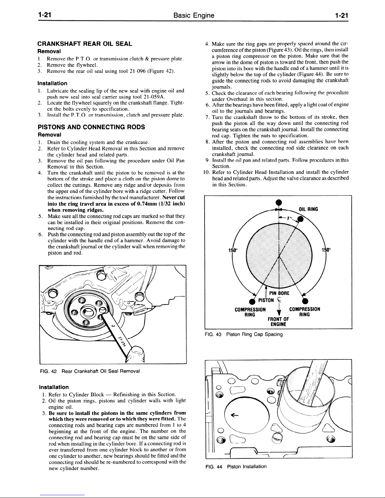
l-21
Basic Engine
l-21
CRANKSHAFT REAR OIL SEAL
Removal
1. Remove the P.T.O. or transmission clutch & pressure plate.
2.
Remove the flywheel.
3. Remove the rear oil seal using tool 2 l-096 (Figure 42).
IInstallation
I. Lubricate the sealing lip of the new seal with engine oil and
push new seal into seal carrier using tool 2 1-059A.
2. Locate the flywheel squarely on the crankshaft flange. Tighten the bolts evenly to specification.
3. Install the P.T.O. or transmission, clutch and pressure plate.
PISTONS AND CONNECTING RODS
Removal
1. Drain the cooling system and the crankcase.
2. Refer to Cylinder Head Removal in this Section and remove
the cylinder head and related parts.
3. Remove the oil pan following the procedure under Oil Pan
Removal in this Section.
4. Turn the crankshaft until the piston to be removed is at the
bottom of the stroke and place a cloth on the piston dome
to
collect the cuttings. Remove any ridge and/or deposits from
the upper end of the cylinder bore with a ridge cutter. Follow
the instructions furnished by the tool manufacturer.
Never cut
into the ring travel area in excess of Q.74mm (I/32 inch)
when removing ridges.
5. Make sure all the connecting rod caps are marked so that they
can be installed in their original positions. Remove the con-
necting rod cap.
6. Push the connecting rod and piston assembly out the top of the
cylinder with the handle end of a hammer. Avoid damage to
the crankshaft journal or the cylinder wall when removing the
piston and rod.
FIG. 42 Rear Crankshaft Oil Seal Removal
Installation
1. Refer to Cylinder Block - Refinishing in this Section.
2. Oil the piston rings, pistons and cylinder walls with light
engine oil.
3. Be sure to install the pistons in the same cylinders from
which they were removed or to which they were fitted.
The
connecting rods and bearing caps are numbered from 1 to 4
beginning at the front of the engine. The number on the
connecting rod and bearing cap must be on the same side of
rod when installing in the cylinder bore. If a connecting rod is
ever transferred from one cylinder block to another or from
one cylinder to another, new bearings should be fitted and the
connecting rod should be re-numbered to correspond with the
new cylinder number.
4. Make sure the ring gaps are properly spaced around the circumference of the piston (Figure 43). Oil the rings, then install
a piston ring compressor on the piston. Make sure that the
arrow in the dome of piston is toward the front, then push the
piston into its bore with the handle end of a hammer until it is
slightly below the top of the cylinder (Figure 44). Be sure to
guide the connecting rods to avoid damaging the crankshaft
journals.
5. Check the clearance of each bearing following the procedure
under Overhaul in this section.
6.
After the bearings have been fitted, apply a light coat of engine
oil to the journals and bearings.
7. Turn the crankshaft throw to the bottom of its stroke, then
push the piston all the way down until the connecting rod
bearing seats on the crankshaft journal. Install the connecting
rod cap. Tighten the nuts to specification.
8. After the piston and connecting rod assemblies have been
installed, check the connecting rod side clearance on each
crankshaft journal.
9. Install the oil pan and related parts. Follow procedures in this
Section.
IO. Refer to Cylinder Head Installation and install the cylinder
head and related parts. Adjust the valve clearance as described
in this Section.
1 Id”
P
COMPRESSION
i
COMPRESSION
RING RING
FRONT OF
ENGINE
FIG. 43 Piston Ring Cap Spacing
FIG. 44 Piston Installation

l-22
Basic Engine
I-22
11. Fill and bleed the cooling system. Fill the crankcase.
12. Start the engine and check for oil pressure. Operate theengine
at fast idle and check for oil and coolant leaks.
13. Operate the engine until engine temperatures have stabilized.
Check and adjust the ignition timing. Adjust the engine idle
speed and fuel mixture to the specifications.
OIL FILTER
Removal
Place a drip pan under the filter. Unscrew the filter from the
adapter fitting. Clean the adapter filter recess.
llnstallation
I. Coat the gasket on the replacement filter with oil. Position the
filter on the adapter fitting. Hand tighten the filter until the
gasket contacts the adapter face, then aavance it l/2 turn.
2. Operate the engine at fast idle, and check for oil leaks. If oil
leaks are evident, perform the necessary repairs to correct the
leakage. Check the oil level and fill the crankcase as required.
DISASSEMBLY AND ASSEMBLY
ENGINE ASSEMBLY
Disassembly
1. Mount the engine on a stand and drain crankcase.
2. Disconnect the fuel line at the fuel pump and carburetor.
3. Disconnect the spark plug leads, remove them from the clip
on the rocker cover and position out of the way.
4. Disconnect the water outlet and crankcase ventilation hoses at
the intake manifold.
5. Disconnect the wire from the temperature gauge sending unit.
6. Disconnect the throttle rod, and the distributor vacuum advance hose from the carburetor.
7. Remove the governor mounting bolts and remove governor
and drive belt.
8. Remove the thermostat housing and thermostat.
9. Remove the rocker arm cover and gasket.
10. Remove the rocker arm shaft bolts evenly and lift off the
rocker arm shaft assembly.
11. Lift out the push rods from their locations and keep them in
their correct order.
12. Remove the cylinder head bolts and lift off the cylinder head
and gasket. Do not lay the cylinder head flat on its face as
damage to the spark plugs or gasket surface can occur.
13. Remove the fuel pump and oil pump.
14. Remove the dipstick and tube.
15. Remove the distributor and secondary wiring.
16. Remove fan, spacer, pulley and alternator belt.
17. Remove the alternator mounting and adjusting bracket bolts.
Remove alternator.
18. Remove crankshaft pulley.
19. Remove the water pump, front cover and crankshaft oil
slinger.
20. Remove any ridge and/or carbon deposits from the upper end
of the cylinder bores. Move the piston to the bottom of its
travel and place a cloth on the piston head to collect the
cuttings. Remove the cylinder ridge with a ridge cutter. Follow the instructions furnished by the tool manufacturer. Nev-
er cut into the ring travel area in excess of l/32 inch when
removing ridge.
21. Invert the engine on the stand and remove the oil pan and
gaskets.
22. Remove the oil pick up tube and screen.
23. Remove the flywheel and rear engine plate.
24. Remove the rear bearing retainer.
25. Remove the timing chain tensioner.
26. Remove the camshaft sprocket and timing chain.
27. Remove the camshaft thrust plate and the camshaft.
28. Remove the tappets keeping them in their correct order.
29. Make sure all connecting rods and caps are marked so that
they can be installed in their original locations. Partially
loosen the connecting rod bolts several turns and tap them to
release the bearing caps. Remove the bolts completely and
remove the caps. Push the pistons out of the bores and remove
the assemblies.
30. Remove the main bearing caps bolts evenly and lift off each
cap. Lift out the crankshaft and handle with care to avoid
possible fracture or damage to finished surfaces.
3 1. Remove the main bearings from block and cap. Remove the
thrust washers.
32. Disassemble the piston and connecting rod assemblies. Remove the piston rings and the two piston pin snap rings. Push
the piston pin out of each piston.
33. Remove the coolant drain plug and oil pressure sending unit
from the block.
34. Remove the block from the stand.
Assembly
When installing nuts or bolts that must be torqued (refer to the
torque specifications), oil the threads with light weight engine oil.
Do not oil threads that require oil-resistant or water-resistant
sealer.
Start the assembly by examining the block and crankshaft to
determine the bearings to be used. The block with standard main
bearing bores is unmarked. With 0.38mm (0.015 in.) oversized
main bearing bores, the bearing caps are marked with white paint
(Figure 45).
FIG. 45 Main Bearing Cap Markings
The crankshaft main bearing journals of standard diameter
came in 2 size categories and are either unmarked or have a yellow
paint mark on the first counterweight (Figure 46). See specifications for dimensions.
FIG. 46 Main Bearing Journal Markings

l-23
Basic Engine
l-23
The standard diameter connecting rod journals are unmarked.
Where the connecting rod journals are 0.25 mm (.OlO in.)
undersize, the crankshaft is marked with a green paint spot on the
web next to the connecting rod bearing journal number one, as
shown in Figure 47.
FIG.
47
Connecting Rod Journal Markings
The standard main bearing and connecting rod bearing inserts
have no color marking. Bearing inserts for undersize (u/s) crankshafts or oversize (o/s) cylinder blocks have corresponding inscriptions on the back.
When new bearing inserts are selected they should be measured
to ensure that they are the appropriate size. Be sure that the
specified tolerances are adhered to by measuring bearing journals
and block bores individually with the bearing inserts installed.
1. Mount the block in the stand inverted.
2. Install the coolant drain plug and oil pressure sending unit.
3. Place the upper main bearing inserts in position in the bore
with the tang fitting in the slot provided.
4. Install the lower main bearing inserts in the bearing caps.
5. Carefully lower the crankshaft into place.
Be careful not to
damage the bearing surfaces.
Check the clearance of each
main bearing following the procedures in the Overhaul
Section.
6. Install the thrust washers to the center main. Apply a light coat
of oil to the journals and bearings. Install the main bearing
caps. Tighten the main bearing cap bolts evenly to specifications and check crankshaft rotation.
7. Check the crankshaft end play.
8. Install the tappets into their respective bores.
9. Oil the camshaft journals with heavy engine oil and apply
Lubriplate or equivalent to all lobes and then carefully slide it
through the bearings.
10. Position the camshaft thrust plate and tighten the attaching
bolts to specifications. Check the camshaft end play. Bend the
locking tabs to secure the bolts.
11. Install the camshaft sprocket and timing chain aligning the
timing marks on the camshaft and crankshaft sprockets (Figure 34). Tighten the attaching bolts to specification and bend
up the locking plate tabs.
12. Position the timing chain tehsioner arm on the pivot pin and
install the tensioner (Figure 48).
13. Install a new oil seal to the front cover using tool 21-046.
14. Install the oil slinger on the crankshaft and position the front
cover gasket in place using oil resistant sealer. Locate the front
cover, aligning the seal to the crankshaft with pulley (Figure
35). Tighten the bolts evenly to specification.
15. Install a new oil seal in the rear oil seal carrier using tool 21059A.
16. Position a new gasket on the rear oil seal carrier using oil
resistant sealer. Secure the carrier to the cylinder block. Tighten the bolts evenly to specification.
FIG. 48 Installing Timing Chain Tensioner
17. Assemble the respective pistons to their connecting rods. Be
sure the “F” or “front” on the rod and the arrow on the top of
the piston face the same side (Figure 49). Push the piston pin
into the piston and rod and install the two piston pin snap rings
on service pistons only.
FIG. 49 Connecting Rod and Piston Assembly
18. Install the rings on the piston starting with the oil ring, then
the
second compression ring and the top compression ring. Position the gaps as shown in Figure 43.
19. Rotate the engine in the stand so that the front end is up. Oil the
piston rings and cylinder bores with engine oil. Compress the
rings using a universal piston ring compressor. Install the
piston and connecting rod assemblies into their respective
bores with the arrow on top of the piston pointing toward the
front of the block.
20. Install the connecting rod bearings and check the clearances as
detailed in the Overhaul Section.
21. Oil the bearings and journals with engine oil and install the
connecting rod bearing caps. Tighten the bolts to specification. Check the connecting rod side clearance.
22. Rotate the engine to the inverted position. Replace the oil
pump pick up tube and screen. Press the tubes to the fulldepth
of the counterbored holes.
23. Position the flywheel squarely on the crankshaft flange. Tighten the attaching bolts evenly to specification.
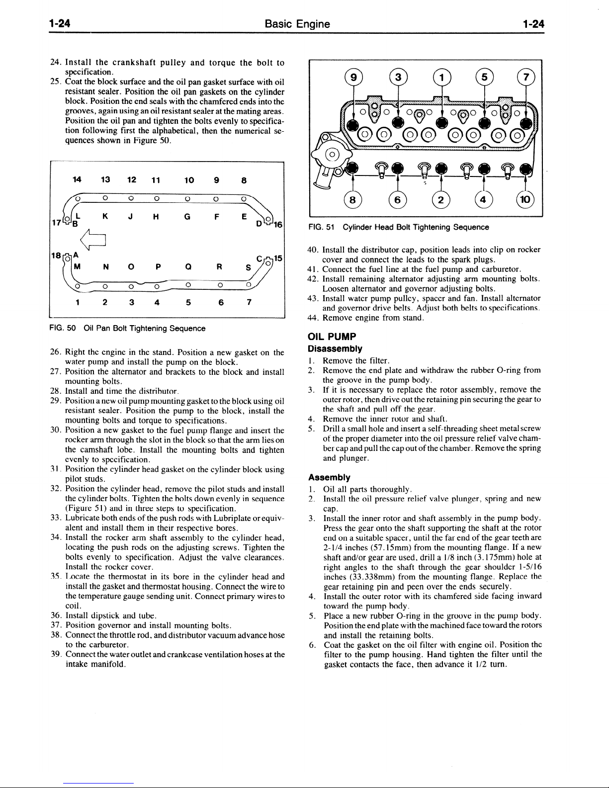
l-24
24. Install the crankshaft pulley and torque the bolt to
specification.
25. Coat the block surface and the oil pan gasket surface with oil
resistant sealer. Position the oil pan gaskets on the cylinder
block. Position the end seals with the chamfered ends into the
grooves, again using an oil resistant sealer at the mating areas.
Position the oil pan and tighten the bolts evenly to specifica-
tion following first the alphabetical, then the numerical se-
quences shown in Figure 50.
Basic Engine
l-24
14 13 12 11
0
0
L K J t-i
0
10
0
G
9
0
F E
8
0
M N 0 P 0 R
0
o- f 0,
1
2 3 4 5
FIG. 50 Oil Pan Bolt Tightening Sequence
26. Right the engine in the stand. Position a new gasket on the
water pump and install the pump on the block.
27. Position the alternator and brackets to the block and install
mounting bolts.
28. Install and time the distributor.
29. Position a new oil pump mounting gasket to the block using oil
resistant sealer Position the pump to the block, install the
mounting bolts and torque to specifications.
30. Position a new gasket to the fuel pump flange and insert the
rocker arm through the slot in the block so that the arm lieson
the camshaft lobe. Install the mounting bolts and tighten
evenly to specification.
3 1. Position the cylinder head gasket on the cylinder block using
pilot studs.
32. Position the cylinder head, remove the pilot studs and install
the cylinder bolts. Tighten the bolts down evenly in sequence
(Figure 51) and in three steps to specification.
33. Lubricate both ends of the push rods with Lubriplate or equivalent and install them in their respective bores.
34. Install the rocker arm shaft assembly to the cylinder head,
locating the push rods on the adjusting screws. Tighten the
bolts evenly to specification. Adjust the valve clearances.
Install the rocker cover.
35. Locate the thermostat in its bore in the cylinder head and
install the gasket and thermostat housing. Connect the wire to
the temperature gauge sending unit. Connect primary wires to
36. Install dipstick and tube.
37. Position governor and install mounting bolts.
38. Connect the throttle rod, and distributor vacuum advance hose
to the carburetor.
39. Connect the water outlet and crankcase ventilation hoses at the
intake manifold.
0 0
6 7
FIG. 51 Cylinder Head Bolt Tightening Sequence
40. Install the distributor cap, position leads into clip on rocker
cover and connect the leads to the spark plugs.
41. Connect the fuel line at the fuel pump and carburetor.
42. Install remaining alternator adjusting arm mounting bolts.
Loosen alternator and governor adjusting bolts.
43. Install water pump pulley, spacer and fan. Install alternator
and governor drive belts. Adjust both belts to specifications.
44. Remove engine from stand.
OIL PUMP
Disassembly
1. Remove the filter.
2. Remove the end plate and withdraw the rubber O-ring from
the groove in the pump body.
3. If it is necessary to replace the rotor assembly, remove the
outer rotor, then drive out the retaining pin securing the gear to
the shaft and pull off the gear.
4. Remove the inner rotor and shaft.
5. Drill a small hole and insert a self-threading sheet metal screw
of the proper diameter into the oil pressure relief valve chamber cap and pull the cap out of the chamber. Remove the spring
and plunger.
Assembly
1. Oil all parts thoroughly.
2. Install the oil pressure relief valve plunger, spring and new
cap.
3. Install the inner rotor and shaft assembly in the pump body.
Press the gear onto the shaft supporting the shaft at the rotor
end on a suitable spacer, until the far end of the gear teeth are
2- l/4 inches (57.15mm) from the mounting flange. If a new
shaft and/or gear are used, drill a l/8 inch (3.175mm) hole at
right angles to the shaft through the gear shoulder l-51 16
inches (33.338mm) from the mounting flange. Replace the
gear retaining pin and peen over the ends securely.
4. Install the outer rotor with its chamfered side facing inward
toward the pump body.
5. Place a new rubber O-ring in the groove in the pump body.
Position the end plate with the machined face toward the rotors
and install the retaining bolts.
6. Coat the gasket on the oil filter with engine oil. Position the
filter to the pump housing. Hand tighten the filter until the
gasket contacts the face, then advance it l/2 turn.
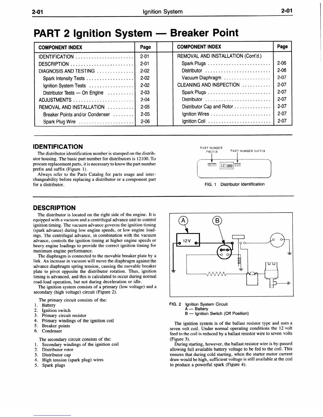
2-01
Ignition System
2-01
PART
COMPONENT INDEX
IDENTIFICATION
DESCRIPTION
DIAGNOSIS AND TESTING
Spark Intensity Tests
Ignition System Tests
Distributor Tests - On Engine
ADJUSTMENTS
REMOVAL AND INSTALLATION
Breaker Points and/or Condenser
Spark Plug Wire
2 Ignition System -
Page
......................
.........................
..............
..................
.................
..........
.......................
..........
........
.....................
2-01
2-01
2-02
2-02
2-02
2-03
2-04
2-05
2-05
2-06
IDENTIFICATION
The distributor identification number is stamped on the distributor housing. The basic part number for distributors is 12 100. To
procure replacement parts, it is necessary to know the part number
prefix and suffix (Figure 1).
Always refer to the Parts Catalog for parts usage and inter-
changeability before replacing a distributor or a component part
for a distributor.
Breaker Point
COMPONENT INDEX
REMOVAL AND INSTALLATION (Cont’d.)
Spark Plugs
Distributor
Vacuum Diaphragm
CLEANING AND INSPECTION
Spark Plugs
Distributor
Distributor Cap and Rotor
Ignition Wires
Ignition Coil
........................
......................... 2-06
.................. 2-07
........................
.........................
.............. 2-07
.......................
........................
PART NUMBER
PREFIX
FIG. 1 Distributor identification
PART NUMBER SUFFIX
...........
Page
2-06
2-07
2-07
2-07
2-07
2-07
DESCRIPTION
The distributor is located on the right side of the engine. It is
equipped with a vacuum and a centrifugal advance unit to control
ignition timing. The vacuum advance governs the ignition timing
(spark advance) during low engine speeds, or low engine loadings. The centrifugal advance, in combination with the vacuum
advance, controls the ignition timing at higher engine speeds or
heavy engine loadings to provide the correct ignition timing for
maximum engine performance.
The diaphragm is connected to the movable breaker plate by a
link. An increase in vacuum will move the diaphragm against the
advance diaphragm spring tension, causing the movable breaker
plate to pivot opposite the distributor rotation. Thus, ignition
timing is advanced, and this is calculated to occur during normal
road-load operation, but not during deceleration or idle.
The ignition system consists of a primary (low voltage) and a
secondary (high voltage) circuit (Figure 2).
The primary circuit consists of the:
1. Battery
2. Ignition switch
3. Primary circuit resistor
4. Primary windings of the ignition coil
5. Breaker points
6. Condenser
The secondary circuit consists of the:
1. Secondary windings of the ignition coil
2. Distributor rotor
3. Distributor cap
4. High tension (spark plug) wires
5. Spark plugs
FIG. 2 Ignition System Circuit
A - Battery
B - ignition Switch (Off Position)
The ignition system is of the ballast resistor type and uses a
seven volt coil. Under normal operating conditions the 12 volt
feed to the coil is reduced by a ballast resistor wire to seven volts
(Figure 3).
During starting, however, the ballast resistor wire is by-passed
allowing full available battery voltage to be fed to the coil. This
ensures that during cold starting, when the starter motor current
draw would be high, sufficient voltage is still available at the coil
to produce a powerful spark (Figure 4).

ignition System
FIG. 3 Ignition Switch in the “On” Position
G-
Ballast Resistor
FIG. 4
Ignition Switch in the “Start” Position
C - Starter Solenoid
E - Distributor
D-
Starter Motor
F - Ignition Coil
DIAGNOSIS AND TESTING
Ignition system troubles are caused by a failure in the primary
and/or the secondary circuit, incorrect ignition timing, or incorrect distributor advance. Circuit failures may be caused by shorts,
corroded or dirty terminals, loose connections, defective wire
insulation, cracked distributor cap or rotor, defective distributor
points, fouled spark plugs, or by improper dwell angle.
If engine starting or operating trouble is attributed to the ignition system, start the engine and verify the complaint. On engines
that will not start, be sure there is gasoline in the fuel tank and that
fuel is reaching the carburetor. Then locate the ignition system
problem by an oscilloscope test or by a spark intensity test.
SPARK INTENSITY TESTS
Trouble Isolation
1. Connect auxiliary starter switch in the starting circuit.
2.
Remove the coil high tension lead from the distributor cap.
3. Turn on the ignition switch.
4. While holding the high tension lead approximately 3/16 inch
from the cylinder head or any other good ground, crank the
engine with an auxiliary starter switch.
If the spark is good, the trouble lies in the secondary circuit.
If there is no spark or a weak spark, the trouble is in theprimary
circuit, coil to distributor high tension lead, or the coil.
Primary Circuit
A breakdown or energy loss in the primary circuit can be caused
by: defective primary wiring, or loose or corroded terminals;
burned, shorted, sticking or improperly adjusted breaker points,
condenser or an open or shorted coil.
A complete test of the primary circuit consists of checking the
circuit from the coil to ground, and the starting ignition circuit.
Excessive voltage drop in the primary circuit will reduce the
secondary output of the ignition coil, resulting in hard starting and
poor performance.
To isolate a trouble in the primary circuit, use a voltmeter and
perform the following test: Battery to Coil, Starting Ignition
Circuit, Coil to Ground, or Breaker Points.
Secondary Circuit
A breakdown or energy loss in the secondary circuit can be
caused by fouled or improperly adjusted spark plugs, defective
high tension wiring or high tension leakage across the coil, distributor cap or rotor resulting from an accumulation of dirt.
To check the spark intensity at the spark plugs, thereby isolating
an ignition problem to a particular cylinder, proceed as follows:
1. Disconnect a spark plug wire.
Check the spark intensity of
one wire at a time.
2. Install a terminal adapter in the terminal of the wire to be
checked. Hold the adapter approximaely 3/16 inch from the
exhaust manifold and crank the engine, using an auxiliary
starter switch. The spark should jump the gap regularly.
3. If the spark intensity of all the wires is satisfactory, the coil,
condenser, rotor, distributor cap and the secondary wires are
probably satisfactory.
If the spark is good at only some wires, check the resistance of
those particular leads.
If the spark is equal at all wires, but weak or intermittent,
check the coil, distributor cap and the coil to distributor high
tension wire. The wire should be clean and bright on the conducting ends, and on the coil tower and distributor sockets. The wire
should fit snugly and be bottomed in the sockets.
IGNITION SYSTEM TESTS
Battery to Coil Voltmeter Test
1. Connect the voltmeter leads as shown in Figure 5.
2. Connect a jumper wire to the distributor terminal of the coil to
a good ground on the distributor housing.
3. Turn the ignition switch on.
4. If the voltmeter reading is between 4.5 and 6.9 volts, the
primary circuit from the battery to the coil is satisfactory.
5. If the voltmeter reading is greater than 6.9 volts, check the
following:
l
The battery and cables for loose connections or corrosion
l
The primary insulation, broken strands, and loose or corroded terminals
6. If the voltmeter reading is less than 4.5 volts the ignition
resistor should be replaced.
l
Check the starter-relay-to-ignition switch for damage.
 Loading...