

Page 1

Table of Contents
Introduction 4
Instrument Cluster 12
Warning lights and chimes 12
Gauges 17
Entertainment Systems 20
AM/FM stereo 20
AM/FM stereo with CD 21
Auxiliary input jack (Line in) 23
Bluetooth system 25
Climate Controls 35
Manual heating and air conditioning 35
Rear window defroster 37
Lights 38
Headlamps 38
Turn signal control 41
Bulb replacement 42
Driver Controls 50
Windshield wiper/washer control 50
Steering wheel adjustment 51
Power windows 53
Mirrors 54
Speed control 55
Locks and Security 61
Keys 61
Anti-theft system 66
2010 Transit Connect (tst)
Owners Guide (own2002), 1st Printing
USA (fus)
1
Page 2

Table of Contents
Seating and Safety Restraints 70
Seating 70
Safety restraints 80
Airbags 92
Child restraints 104
Tires, Wheels and Loading 122
Tire information 124
Tire inflation 126
Tire Pressure Monitoring System (TPMS) 138
Vehicle loading 146
Trailer towing 151
Recreational towing 152
Driving 153
Starting 153
Brakes 157
AdvanceTrac威 160
Transmission operation 167
Reverse sensing system 169
Roadside Emergencies 172
Getting roadside assistance 172
Hazard flasher control 173
Fuel pump shut-off switch 174
Fuses and relays 174
Changing tires 181
Wheel lug nut torque 189
Jump starting 190
Wrecker towing 195
Customer Assistance 197
Reporting safety defects (U.S. only) 203
Reporting safety defects (Canada only) 203
Cleaning 204
2
Page 3

Table of Contents
Maintenance and Specifications 211
Engine compartment 213
Engine oil 215
Battery 218
Engine coolant 220
Fuel information 226
Air filter(s) 240
Part numbers 241
Maintenance product specifications and capacities 242
Engine data 245
Accessories 249
Ford Extended Service Plan 251
Index 254
All rights reserved. Reproduction by any means, electronic or mechanical
including photocopying, recording or by any information storage and retrieval
system or translation in whole or part is not permitted without written
authorization from Ford Motor Company. Ford may change the contents without
notice and without incurring obligation.
Copyright © 2009 Ford Motor Company
3
Page 4

Introduction
CONGRATULATIONS
Congratulations on acquiring your new Ford. Please take the time to get
well acquainted with your vehicle by reading this handbook. The more
you know and understand about your vehicle, the greater the safety and
pleasure you will derive from driving it.
For more information on Ford Motor Company and its products visit the
following website:
• In the United States: www.ford.com
• In Canada: www.ford.ca
• In Australia: www.ford.com.au
• In Mexico: www.ford.com.mx
Additional owner information is given in separate publications.
This Owner’s Guide describes every option and model variant available
and therefore some of the items covered may not apply to your
particular vehicle. Furthermore, due to printing cycles it may describe
options before they are generally available.
Remember to pass on this Owner’s Guide when reselling the vehicle. It
is an integral part of the vehicle.
WARNING: Fuel pump shut-off switch: In the event of an
accident the safety switch will automatically cut off the fuel
supply to the engine. The switch can also be activated through sudden
vibration (e.g. collision when parking). To reset the switch, refer to the
Fuel pump shut-off switch in the Roadside Emergencies chapter.
SAFETY AND ENVIRONMENT PROTECTION
Warning symbols in this guide
How can you reduce the risk of personal injury to yourself or others? In
this guide, answers to such questions are contained in comments
highlighted by the warning triangle symbol. These comments should be
read and observed.
4
Page 5
Introduction
Warning symbols on your vehicle
When you see this symbol, it is
imperative that you consult the
relevant section of this guide before
touching or attempting adjustment
of any kind.
Protecting the environment
We must all play our part in
protecting the environment. Correct
vehicle usage and the authorized
disposal of waste, cleaning and
lubrication materials are significant
steps towards this aim. Information in this respect is highlighted in this
guide with the tree symbol.
CALIFORNIA Proposition 65 Warning
WARNING: Engine exhaust, some of its constituents, and
certain vehicle components contain or emit chemicals known to
the State of California to cause cancer and birth defects or other
reproductive harm. In addition, certain fluids contained in vehicles and
certain products of component wear contain or emit chemicals known
to the State of California to cause cancer and birth defects or other
reproductive harm.
PERCHLORATE MATERIAL
Certain components of this vehicle such as airbag modules, seat belt
pretensioners, and button cell batteries may contain Perchlorate Material
– Special handling may apply for service or vehicle end of life disposal.
See www.dtsc.ca.gov/hazardouswaste/perchlorate.
BREAKING-IN YOUR VEHICLE
Your vehicle does not need an extensive break-in. Try not to drive
continuously at the same speed for the first 1,000 miles (1,600 km) of
new vehicle operation. Vary your speed frequently in order to give the
moving parts a chance to break in.
Drive your new vehicle at least 1,000 miles (1,600 km) before towing a
trailer. For more detailed information about towing a trailer, refer to
Trailer towing in the Tires, Wheels and Loading chapter.
5
Page 6

Introduction
Do not add friction modifier compounds or special break-in oils since
these additives may prevent piston ring seating. See Engine oil in the
Maintenance and Specifications chapter for more information on oil
usage.
SPECIAL NOTICES
New Vehicle Limited Warranty
For a detailed description of what is covered and what is not covered by
your vehicle’s New Vehicle Limited Warranty, refer to the Warranty
Guide/Customer Information Guide that is provided to you along with
your Owner’s Guide.
Special instructions
For your added safety, your vehicle is fitted with sophisticated electronic
controls.
WARNING: Please read the section Airbag Supplemental
Restraint System (SRS) in the Seating and Safety Restraints
chapter. Failure to follow the specific warnings and instructions could
result in personal injury.
WARNING: Front seat mounted rear-facing child or infant seats
should NEVER be placed in front of an active passenger airbag.
Notice to owners of pickup trucks and utility type vehicles
WARNING: Utility vehicles have a significantly higher rollover
rate than other types of vehicles.
Before you drive your vehicle, please read this Owner’s Guide carefully.
Your vehicle is not a passenger car. As with other vehicles of this type,
failure to operate this vehicle correctly may result in loss of vehicle
control, vehicle rollover, personal injury or death.
Using your vehicle as an ambulance
Do not use this vehicle as an ambulance.
Your vehicle is not equipped with the Ford Ambulance Preparation
Package.
6
Page 7

Introduction
DATA RECORDING
Service Data Recording
Service data recorders in your vehicle are capable of collecting and
storing diagnostic information about your vehicle. This potentially
includes information about the performance or status of various systems
and modules in the vehicle, such as engine, throttle, steering or brake
systems. In order to properly diagnose and service your vehicle, Ford
Motor Company, Ford of Canada, and service and repair facilities may
access or share among them vehicle diagnostic information received
through a direct connection to your vehicle when diagnosing or servicing
your vehicle. For U.S. only (if equipped), if you choose to use the SYNC威
Vehicle Health Report, you consent that certain diagnostic information
may also be accessed electronically by Ford Motor Company and Ford
authorized service facilities, and that the diagnostic information may be
used for any purpose. See your SYNC威 supplement for more information.
Event Data Recording
Other modules in your vehicle — event data recorders — are
capable of collecting and storing data during a crash or near
crash event. The recorded information may assist in the
investigation of such an event. The modules may record
information about both the vehicle and the occupants, potentially
including information such as:
• how various systems in your vehicle were operating;
• whether or not the driver and passenger seatbelts were
buckled;
• how far (if at all) the driver was depressing the accelerator
and/or the brake pedal;
• how fast the vehicle was traveling;
• where the driver was positioning the steering wheel; and
• longitude and latitude of vehicle at last location, using GPS
technology and advanced vehicle sensors.
To access this information, special equipment must be directly
connected to the recording modules. Ford Motor Company and
Ford of Canada do not access event data recorder information
without obtaining consent, unless pursuant to court order or
where required by law enforcement, other government authorities
or other third parties acting with lawful authority. Other parties
7
Page 8

Introduction
may seek to access the information independently of Ford Motor
Company and Ford of Canada. To the extent that any law
pertaining to Event Data Recording applies to SYNC威 or its
features, please note the following: Once 911 Assist (if equipped)
is enabled (set ON), 911 Assist may, through any paired and
connected cell phone, disclose to emergency services that the
vehicle has been in a crash involving the deployment of an airbag
or, in certain vehicles, the activation of the fuel pump shut-off.
Certain versions or updates to 911 Assist may also be capable of
electronically or verbally disclosing to 911 operators the vehicle
location, and/or other details about the vehicle or crash to assist
911 operators to provide the most appropriate emergency
services. If you do not want to disclose this information, do not
activate the feature. See your SYNC威 supplement for more
information. Additionally, when you connect to Traffic, Directions
and Information (if equipped, U.S. only), the service uses GPS
technology and advanced vehicle sensors to collect the vehicle’s
current location, travel direction, and speed (“vehicle travel
information”) only to help provide you with the directions, traffic
reports, or business searches you request. If you do not want
Ford or its vendors to receive this information, do not activate
the service. Ford Motor Company and the vendors it uses to
provide you with this information do not store your vehicle travel
information. For more information, see Traffic, Directions and
Information, Terms and Conditions. See your SYNC威 supplement
for more information.
Vehicle Modification Data Recording
Some aftermarket products may cause severe engine and/or transmission
damage; refer to the What is not covered section in The new vehicle
limited warranty for your vehicle chapter of your vehicle’s Warranty
Guide for more information. Some vehicles are equipped with
Powertrain Control Systems that can detect and store information about
vehicle modifications that, for example, increase horsepower and torque
output; this information cannot be erased and will stay in the system’s
memory even if the modification is removed. When a dealer or repair
facility works on your vehicle, it may be necessary for them to access the
information in the Powertrain Control System. This information will likely
identify if any unauthorized modifications have been made to the system,
which may be used to determine if the warranty has been violated and if
repairs will be covered by warranty.
8
Page 9

Introduction
CELL PHONE USE
The use of Mobile Communications Equipment has become increasingly
important in the conduct of business and personal affairs. However,
drivers must not compromise their own or others’ safety when using
such equipment. Mobile Communications can enhance personal safety
and security when appropriately used, particularly in emergency
situations. Safety must be paramount when using mobile communications
equipment to avoid negating these benefits.
Mobile Communication Equipment includes, but is not limited to cellular
phones, pagers, portable email devices, in-vehicle communications
systems, telematics devices and portable two-way radios.
WARNING: Driving while distracted can result in loss of vehicle
control, accident and injury. Ford strongly recommends that
drivers use extreme caution when using any device that may take their
focus off the road. The driver’s primary responsibility is the safe
operation of their vehicle. Only use cell phones and other devices not
essential to the driving task when it is safe to do so.
EXPORT UNIQUE (NON–UNITED STATES/CANADA) VEHICLE SPECIFIC INFORMATION
For your particular global region, your vehicle may be equipped with
features and options that are different from the features and options that
are described in this Owner’s Guide. A market unique supplement may
be supplied that complements this book. By referring to the market
unique supplement, if provided, you can properly identify those features,
recommendations and specifications that are unique to your vehicle. This
Owner’s Guide is written primarily for the U.S. and Canadian Markets.
Features or equipment listed as standard may be different on units built
for Export. Refer to this Owner’s Guide for all other required
information and warnings.
9
Page 10
Introduction
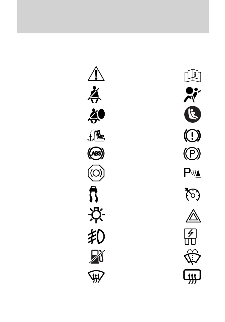
These are some of the symbols you may see on your vehicle.
Vehicle Symbol Glossary
Safety Alert
Fasten Safety Belt Airbag - Front
Airbag - Side
Child Seat Tether
Anchor
Anti-Lock Brake System Parking Brake System
Brake Fluid Non-Petroleum Based
Stability Control System Speed Control
Master Lighting Switch Hazard Warning Flasher
Fog Lamps-Front Fuse Compartment
See Owner’s Guide
Child Seat Lower
Anchor
Brake System
Parking Aid System
Fuel Pump Reset Windshield Wash/Wipe
Windshield
Defrost/Demist
10
Rear Window
Defrost/Demist
Page 11
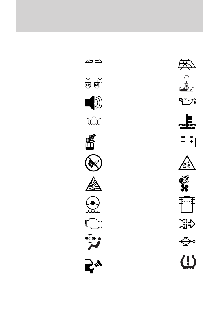
Vehicle Symbol Glossary
Introduction
Power Windows
Front/Rear
Child Safety Door
Lock/Unlock
Power Window Lockout
Interior Luggage
Compartment Release
Panic Alarm Engine Oil
Engine Coolant
Engine Coolant
Temperature
Do Not Open When Hot Battery
Avoid Smoking, Flames,
or Sparks
Battery Acid
Explosive Gas Fan Warning
Power Steering Fluid
Maintain Correct Fluid
Level
Service Engine Soon Engine Air Filter
MAX
MIN
Passenger Compartment
Air Filter
Check Fuel Cap
Jack
Low Tire Pressure
Warning
11
Page 12
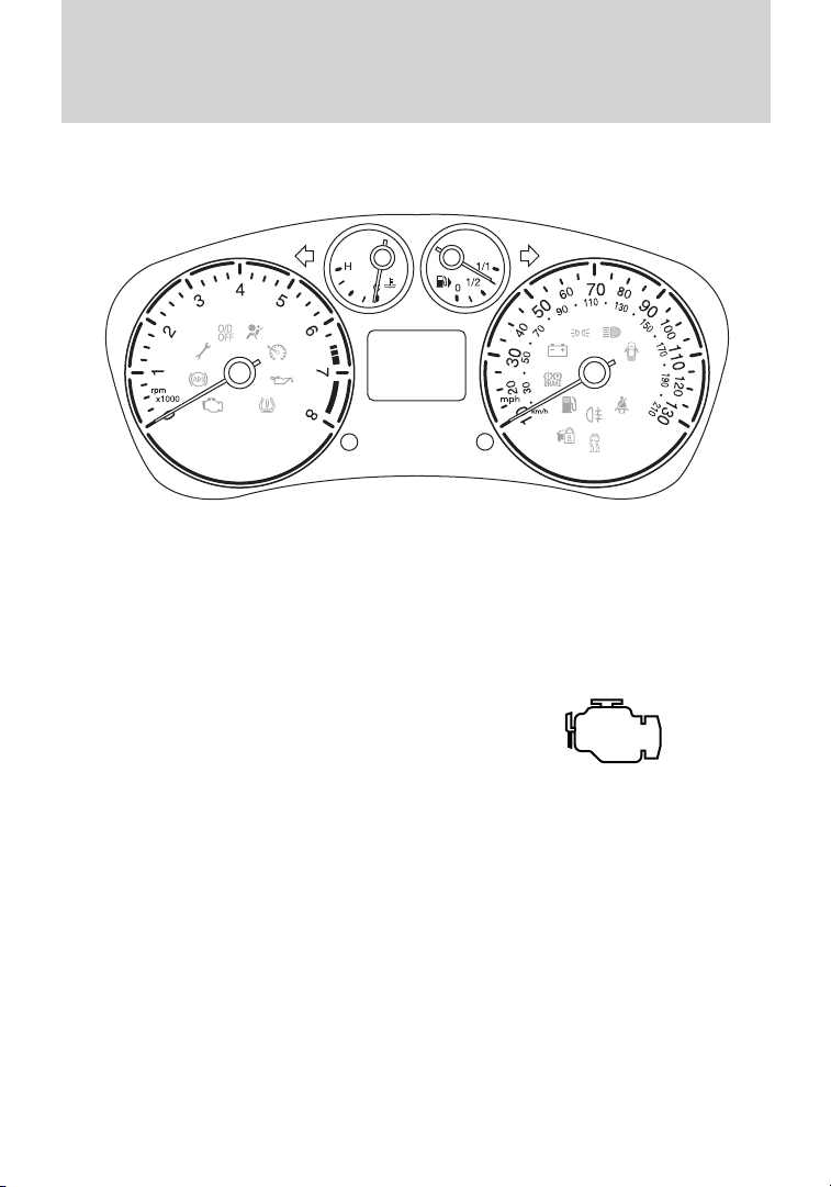
Instrument Cluster
WARNING LIGHTS AND CHIMES
Warning lights and gauges can alert you to a vehicle condition that may
become serious enough to cause expensive repairs. A warning light may
illuminate when a problem exists with one of your vehicle’s functions.
Many lights will illuminate when you start your vehicle to make sure the
bulb works. If any light remains on after starting the vehicle, refer to the
respective system warning light for additional information.
Service engine soon: The Service
engine soon indicator light
illuminates when the ignition is first
turned to the on position to check
the bulb and to indicate whether the vehicle is ready for
Inspection/Maintenance (I/M) testing. Normally, the “Service engine
soon” light will stay on until the engine is cranked, then turn itself off if
no malfunctions are present. However, if after 15 seconds the “Service
engine soon” light blinks eight times, it means that the vehicle is not
ready for I/M testing. See the Readiness for Inspection/Maintenance
(I/M) testing in the Maintenance and Specifications chapter.
Solid illumination after the engine is started indicates the On Board
Diagnostics System (OBD-II) has detected a malfunction. Refer to On
board diagnostics (OBD-II) in the Maintenance and Specifications
chapter. If the light is blinking, engine misfire is occurring which could
damage your catalytic converter. Drive in a moderate fashion (avoid
heavy acceleration and deceleration) and have your vehicle serviced
immediately by your authorized dealer.
12
Page 13
Instrument Cluster
WARNING: Under engine misfire conditions, excessive exhaust
temperatures could damage the catalytic converter, the fuel
system, interior floor coverings or other vehicle components, possibly
causing a fire.
Brake system warning light: To
confirm the brake system warning
light is functional, it will
momentarily illuminate when the
ignition is turned to the on position
when the engine is not running, or in a position between on and start, or
by applying the parking brake when the ignition is turned to the on
position. If the brake system warning light does not illuminate at this
time, seek service immediately from your authorized dealer. Illumination
after releasing the parking brake indicates low brake fluid level and the
brake system should be inspected immediately by your authorized dealer.
WARNING: Driving a vehicle with the brake system warning
light on is dangerous. A significant decrease in braking
performance may occur. It will take you longer to stop the vehicle.
Have the vehicle checked by your authorized dealer. Driving extended
distances with the parking brake engaged can cause brake failure and
the risk of personal injury.
Anti-lock brake system: If the
ABS light stays illuminated or
continues to flash, a malfunction has
been detected, have the system
serviced immediately by your
authorized dealer. Normal braking is still functional unless the brake
warning light also is illuminated.
Airbag readiness: If this light fails
to illuminate when the ignition is
turned to on, continues to flash or
remains on, have the system
serviced immediately by your authorized dealer. A chime will sound
when there is a malfunction in the indicator light.
BRAKE
P!
ABS
13
Page 14

Instrument Cluster
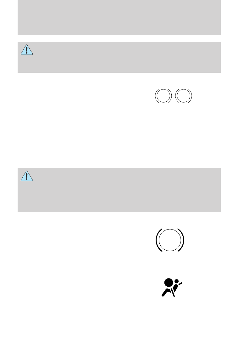
Safety belt: Reminds you to fasten
your front driver and passenger
safety belt. A Belt-Minder威 chime
will also sound to remind you to
fasten your safety belt. Refer to the
Seating and Safety Restraints chapter to activate/deactivate the
Belt-Minder威 chime feature.
Charging system: Illuminates when
the battery is not charging properly.
If it stays on while the engine is
running, there may be a malfunction
with the charging system. Contact your authorized dealer as soon as
possible. This indicates a problem with the electrical system or a related
component.
Engine oil pressure: Illuminates
when the oil pressure falls below the
normal range, refer to Engine oil in
the Maintenance and
Specifications chapter.
Anti-theft system: Flashes when
the SecuriLock™ Passive Anti-theft
system has been activated.
Overdrive off (if equipped):
Illuminates when the overdrive
function of the transaxle has been
turned off, refer to the Driving
chapter. If the light flashes steadily or does not illuminate, have the
transmission serviced soon, or damage may occur.
Speed control (if equipped):
Illuminates when the speed control
is activated. Turns off when the
speed control system is deactivated,
refer to the Instrument cluster
chapter for more information.
14
O/D
OFF
Page 15
Instrument Cluster
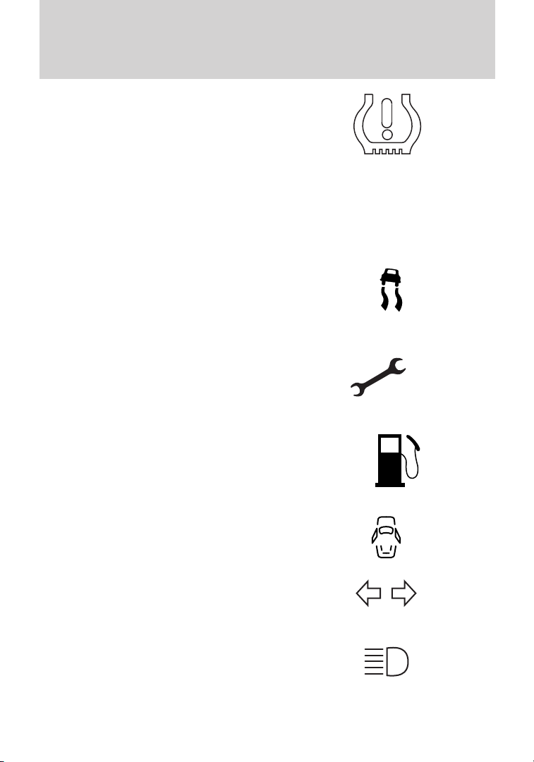
Low tire pressure warning:
Illuminates when your tire pressure
is low. If the light remains on at
start up or while driving, the tire
pressure should be checked. Refer
to Inflating your tires in the Tires, Wheels and Loading chapter. When
the ignition is first turned to on, the light will illuminate for three
seconds to ensure the bulb is working. If the light does not turn on or
begins to flash, have the system inspected by your authorized dealer. For
more information on this system, refer to Tire pressure monitoring
system (TPMS) in the Tires, Wheels and Loading chapter.
AdvanceTrac威/Traction
Control™: Illuminates when the
AdvanceTrac威/Traction Control™ is
active. If the light remains on,
contact your authorized dealer as
soon as possible. Refer to the Driving chapter for more information.
Throttle Control/Transmission:
Illuminates when a powertrain fault
has been detected. Contact your
authorized dealer as soon as
possible.
Low fuel: Illuminates when the fuel
level in the fuel tank is at or near
empty (refer to Fuel gauge in this
chapter).
Door ajar: Illuminates when the
ignition is in the on position and any
door is open.
Turn signal: Illuminates when the
left or right turn signal or the
hazard lights are turned on. If the
indicators stay on or flash faster, check for a burned out bulb.
High beams: Illuminates when the
high-beam headlamps are turned on.
15
Page 16

Instrument Cluster
Headlamps: Illuminates when the
low–beam headlamps are turned on.
Rear fog lamps: Illuminates when
the rear fog lamps are turned on.
Key-in-ignition warning chime: Sounds when the key is left in the
ignition in the off or accessory position and the driver’s door is opened.
Park warning chime: Sounds when the transmission is not in Park, the
driver’s door is opened and the ignition is off or in accessory position.
Headlamps on warning chime: Sounds when the headlamps or parking
lamps are on and the driver’s door is opened.
Seatbelt warning chime: The seatbelt chime sounds when the driver’s
seatbelt is not fastened. When the ignition is in run and the seatbelt is
not fastened, the chime will chime for 6 seconds. The chime will turn off
if the driver’s seatbelt is fastened or if the ignition returns to off or
accessory position.
Beltminder warning chime: This chime periodically sounds to remind
the driver and/or passenger that their seatbelt is unbuckled. The seatbelt
warning lamp in the cluster will also illuminate once vehicle speed has
exceeded 6 mph (10 km/h).
Airbag secondary warning chime: This chime sounds to indicate a
fault with the supplemental restraint system in the event that the airbag
readiness warning light is not operating.
Door ajar warning chime: The door ajar reminder chime informs the
driver that one or more doors are open while the ignition is in the run
position.
16
Page 17
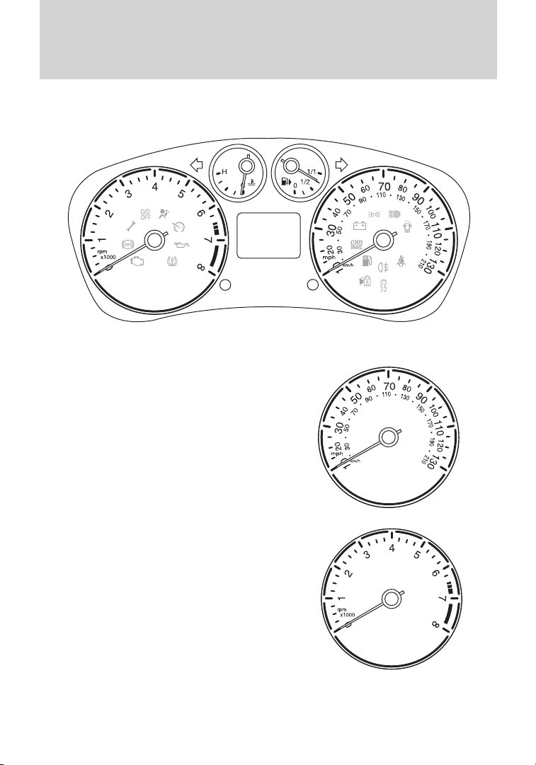
GAUGES
Speedometer: Indicates the
current vehicle speed.
Instrument Cluster
Tachometer: Indicates the engine
speed in revolutions per minute.
Driving with your tachometer
pointer continuously at the top of
the scale may damage the engine.
17
Page 18
Instrument Cluster
Engine coolant temperature
gauge: Indicates engine coolant
temperature. At normal operating
temperature, the needle will be in
the normal range. If it enters the
red section, the engine is
overheating. Stop the vehicle as
soon as safely possible, switch
off the engine and let the engine cool. If it enters the red section
and the service engine soon indicator light illuminates, refer to How fail
safe cooling works in the Maintenance and Specifications chapter.
WARNING: Never remove the coolant reservoir cap while the
engine is running or hot.
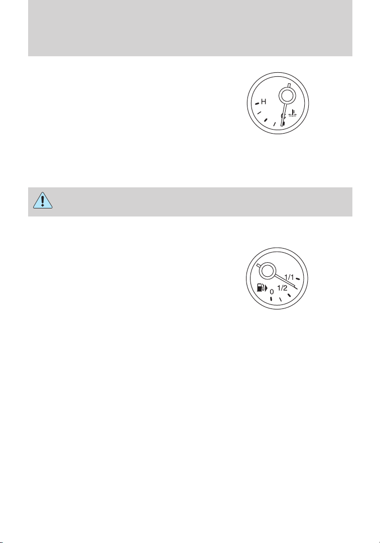
Fuel gauge: Indicates
approximately how much fuel is left
in the fuel tank (when the ignition
is in the on position). The fuel
gauge may vary slightly when the
vehicle is in motion or on a grade.
The symbol of the fuel pump with
the arrow points to the side of the
vehicle that the fuel filler inlet is located.
Refer to Filling the tank in the Maintenance and Specifications
chapter for more information.
18
Page 19
Instrument Cluster
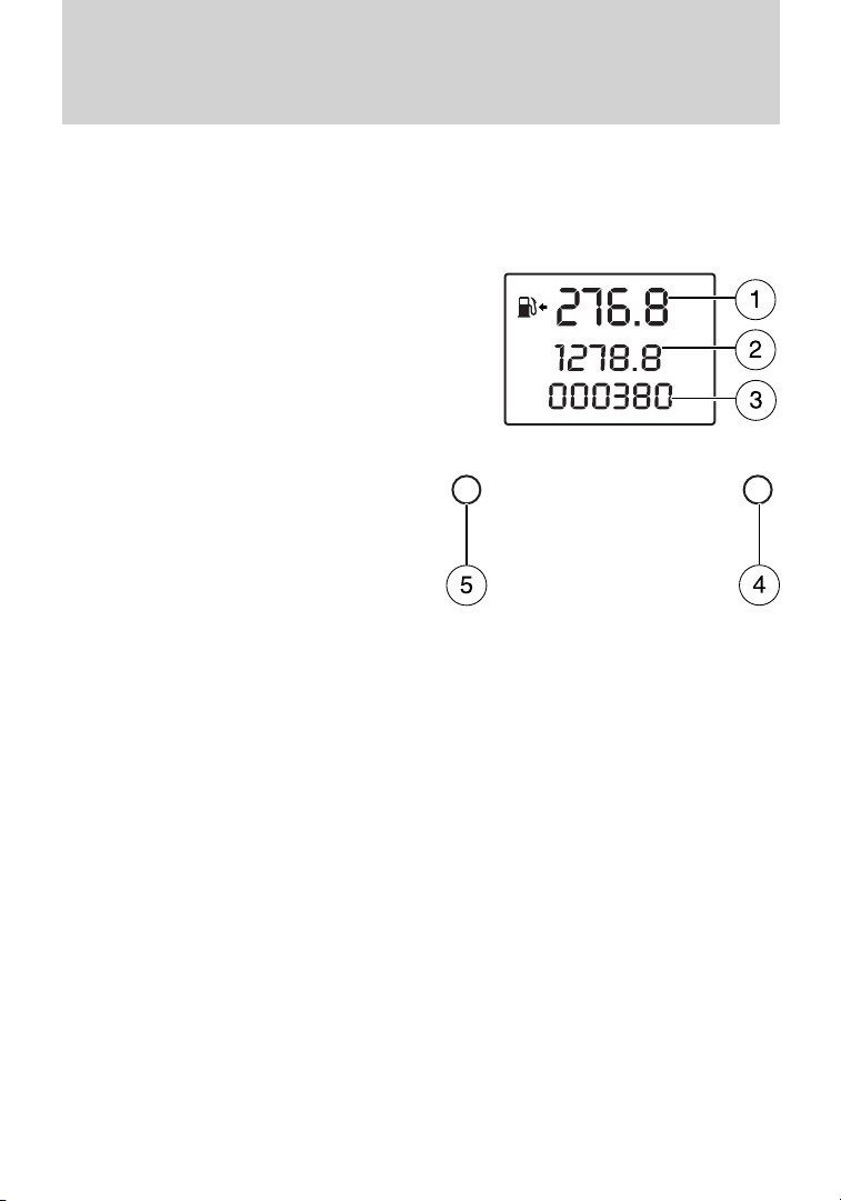
Information display
1. Distance to empty / clock:
Registers the approximate distance
the vehicle can travel before
refuelling is necessary. Clock shows
the current set time.
Switching the display between
“clock” and “distance to
empty”:
• Vehicles with “clock” displayed
normally: Press the Select button
(4) to switch to the “distance to
empty” display.
• Vehicles with “distance to empty”
displayed normally: Press the
Select button (4) to switch to the
“clock” display.
Setting the clock:
Vehicles with AM/FM radio:
Press the Select button (4) until
the time flashes in the display. Press the Select button (4) to set the
time.
Vehicles with AM/FM radio / CD player: Use the radio to set the
time. See Setting the clock in the Entertainment chapter.
2. Trip odometer: Registers the distance of individual journeys. Press
the reset button (5) until the trip odometer resets.
3. Odometer: Registers the miles (kilometers) of the vehicle.
4. Select button: Press to switch between clock and distance to empty.
Also used to set the clock for vehicles equipped with AM/FM radio.
5. Reset button: Press until the trip odometer resets.
Note: The information display will remain on for several minutes after
you switch off the ignition.
If SHON or SHIP ON is displayed, the vehicle shipping mode is switched
on. Have your dealer switch off the vehicle shipping mode.
19
Page 20
Entertainment Systems
AUDIO SYSTEMS
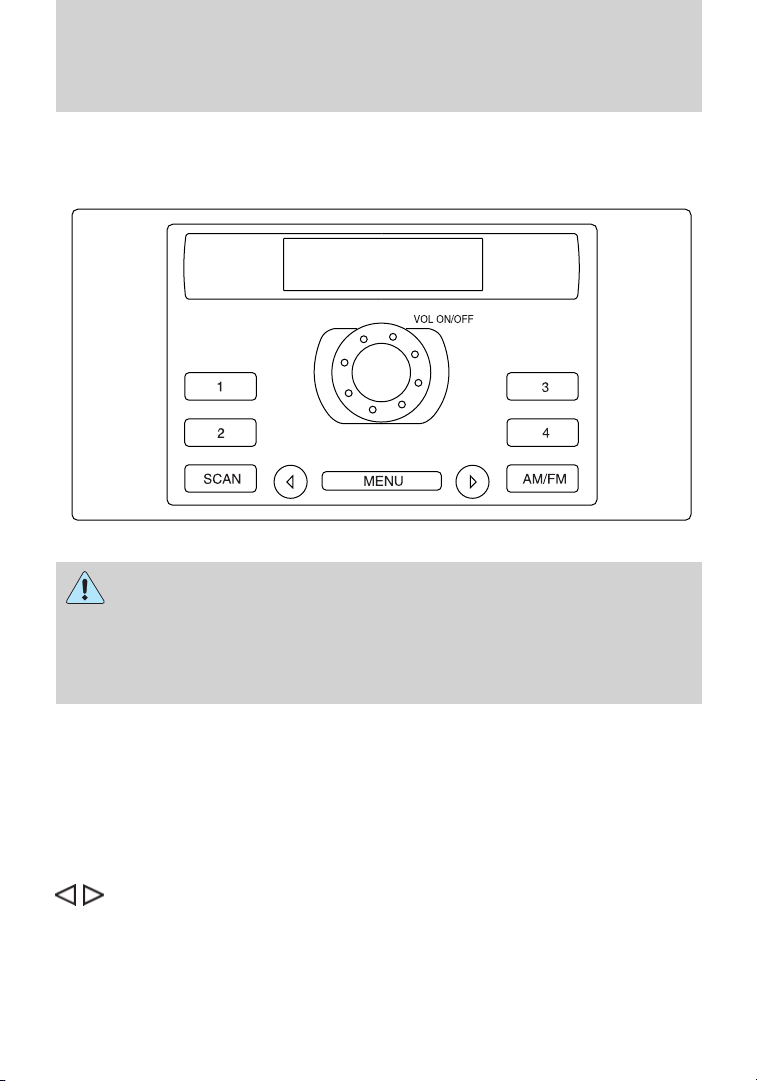
AM/FM stereo (if equipped)
WARNING: Driving while distracted can result in loss of vehicle
control, accident and injury. Ford strongly recommends that
drivers use extreme caution when using any device that may take their
focus off the road. The driver’s primary responsibility is the safe
operation of their vehicle. Only use cell phones and other devices not
essential to the driving task when it is safe to do so.
One hour mode: Press the ON/OFF control to operate the system for
up to an hour with the ignition turned off. The audio will automatically
turn off after one hour.
VOL ON/OFF: Press to turn ON/OFF. Turn to increase/decrease volume.
AM/FM Radio
AM/FM: Press repeatedly to select AM/FM frequency band.
(Seek): Press to access the next strong station on the frequency
band.
SCAN: Press for a brief sampling of all strong radio stations.
(1–4): (Memory Presets): When tuned to any station, press and hold a
preset button until sound returns.
20
Page 21
Entertainment Systems
Sound Adjustments
Press MENU repeatedly to cycle through the following features:
BASS: Press
to adjust the level of bass.
TREBLE: Press
BALANCE: Press to adjust the audio between the left (L) and
right (R) speakers.
FADE: Press
(F) speakers.
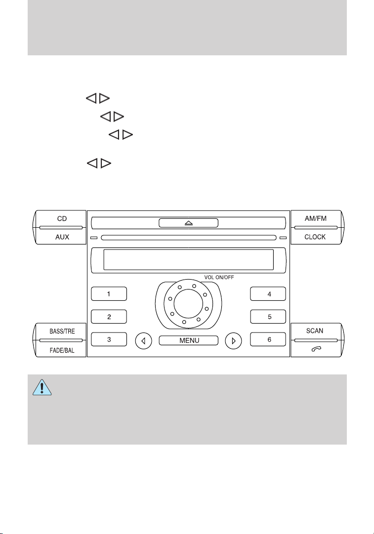
AM/FM stereo with single CD (if equipped)
WARNING: Driving while distracted can result in loss of vehicle
control, accident and injury. Ford strongly recommends that
drivers use extreme caution when using any device that may take their
focus off the road. The driver’s primary responsibility is the safe
operation of their vehicle. Only use cell phones and other devices not
essential to the driving task when it is safe to do so.
to adjust the level of treble.
to adjust the audio between the back (B) and front
One hour mode: Press the ON/OFF control to operate the system for
up to an hour with the ignition turned off. The audio will automatically
turn off after one hour.
VOL ON/OFF: Press to turn ON/OFF. Turn to increase/decrease volume.
21
Page 22

Entertainment Systems
Setting the clock
To set the time or date, turn the radio on and press CLOCK until the
time begins to flash. Press
(date or time). Once the desired selection is flashing, turn the VOL
(Volume) control to adjust the time or date forward/backward. Press
CLOCK again.
AM/FM radio
AM/FM: Press repeatedly to select AM/FM1 and FM2 frequency bands.
(Seek): Press to access the next strong station on the frequency
band.
SCAN: Press for a brief sampling of all strong radio stations.
(1–6): (Memory Presets): When tuned to any station, press and hold a
preset button until sound returns.
Note: If TP appears in the display, it is an indicator that RDS is active.
CD player
To load a CD, simply insert the disc, label side up, into the CD slot.
(Eject): Press to eject the CD.
(Seek): Press to access the previous/next track.
SCAN: Press for a brief sampling of all tracks on the current disc.
Sound Adjustments
BASS/TRE: Press to toggle between bass and treble adjustments. Once
the desired selection appears in the display, press
levels.
FADE/BAL: Press to toggle between fade and balance adjustments.
Once the desired selection appears in the display, press
the audio between front (F) and back (B) and left (L) and right (R)
speakers.
Extra Features
AUX: Press to access auxiliary input jack mode and play music from a
portable player over the vehicle speakers.
(Phone): If your vehicle is equipped with the Bluetooth威 system,
refer to Bluetooth hands free system later in this chapter for more
information. If your vehicle is not equipped with Bluetooth, this control
will not be operational.
22
or to access the desired selection
to adjust the
to adjust
Page 23

Entertainment Systems
MENU: Press repeatedly to access the following features:
MAN: Press < or > to manually advance down or up the chosen
frequency band.
SCAN: Press < or > for a brief sampling of radio stations or CD tracks.
SHUFFLE CD: Select to shuffle the tracks on the current CD.
REPEAT CD: Select to repeat the current CD.
COMP (Compression): Select to bring soft and loud CD passages
together for a more consistent listening level.
CLOCK 24H: Press > to toggle between a 12 and 24 hour clock display.
AVC: Press < or > to decrease/increase the level of automatic volume
control.
ADV MENU: When ADV MENU (Advanced menu) appears in the
display, press and hold MENU to access the following features:
• NEWS ON/OFF: News features are not available in the U.S. and
Canada markets.
• CLIP ON/OFF: Press to turn nominal volume levels on/off.
• VEHICLE ID: Press to view the vehicle’s VIN number.
• BT ON/OFF: Press to turn Bluetooth ON/OFF (if equipped). Refer to
Bluetooth hands free system later in this chapter for more
information
Auxiliary input jack (Line in)
WARNING: Driving while distracted can result in loss of vehicle
control, accident and injury. Ford strongly recommends that
drivers use extreme caution when using any device that may take their
focus off the road. The driver’s primary responsibility is the safe
operation of their vehicle. Only use cell phones and other devices not
essential to the driving task when it is safe to do so.
23
Page 24
Entertainment Systems
The auxiliary input jack allows you
to connect your portable music
player and play music through the
vehicle speakers with high fidelity.
Required equipment:
1. Any portable music player
designed to be used with
headphones
2. An audio extension cable with
stereo male 1/8 in. (3.5 mm)
connectors at each end.
To play your portable music player using the auxiliary input jack:
1. Begin with the vehicle parked and the radio turned off.
2. Ensure that the battery in your portable music player is new or fully
charged and that the device is turned off.
3. Attach one end of the audio extension cable to the headphone output
of your player and the other end of the audio extension cable to the
auxiliary input jack.
4. Turn the radio on, using either a tuned FM station or a CD loaded into
the system. Adjust the volume to a comfortable listening level.
5. Turn the portable music player on and adjust the volume to 1/2 the
volume.
6. Press AUX on the vehicle radio repeatedly until AUX appears in the
display.
You should hear audio from your portable music player although it may
be low.
7. Adjust the sound on your portable music player until it reaches the
level of the FM station or CD by switching back and forth between the
AUX and FM or CD controls.
Troubleshooting:
1. Do not connect the audio input jack to a line level output. Line level
outputs are intended for connection to a home stereo and are not
compatible with the AIJ. The AIJ will only work correctly with devices
that have a headphone output with a volume control.
2. Do not set the portable music player’s volume level higher than is
necessary to match the volume of the CD or FM radio in your audio
system as this will cause distortion and will reduce sound quality. Many
24
Page 25

Entertainment Systems
portable music players have different output levels, so not all players
should be set at the same levels. Some players will sound best at full
volume and others will need to be set at a lower volume.
3. If the music sounds distorted at lower listening levels, turn the
portable music player volume down. If the problems persists, replace or
recharge the batteries in the portable music player.
4. The portable music player must be controlled in the same manner
when it is used with headphones as the AIJ does not provide control
(play, pause, etc.) over the attached portable music player.
5. For safety reasons, connecting or adjusting the settings on your
portable music player should not be attempted while the vehicle is
moving. Also, the portable music player should be stored in a secure
location, such as the center console or the glove box, when the vehicle is
in motion. The audio extension cable must be long enough to allow the
portable music player to be safely stored while the vehicle is in motion.
BLUETOOTH姞 HANDS-FREE SYSTEM (IF EQUIPPED)
Your vehicle may be equipped with Bluetooth威, a wireless technology
which works with your cellular phone to allow you to send and receive
calls in a hands-free manner. Your cellular phone must be Bluetooth
enabled and also be connected (bonded or paired) to the vehicle’s
system. These features allow you to have hands-free conversations while
enabling you to focus your attention on the road.
WARNING: Use extreme caution when using any device or
feature that may take your attention off the road. Your primary
responsibility is the safe operation of the vehicle. Only use
non-essential features and devices when it is safe to do so.
PHONE COMPATIBILITY
While your Bluetooth system supports a variety of features, many are
dependent upon the functionality of your cellular phone with Bluetooth
wireless technology. If there is an incompatibility, the performance of
your system may be significantly degraded. Please refer to
www.fordvehicles.com/transitconnect for any questions.
25
Page 26

Entertainment Systems
Getting started
Pairing (bonding) your phone
The first thing you must do to use the system is to pair (bond) your
Bluetooth enabled cellular phone with your vehicle’s Bluetooth system.
This process allows your phone to communicate with the hands-free
system and ensures that other phones cannot inadvertently do so. You
may pair/bond up to six phones with your Bluetoothsystem.
To pair/connect your phone:
1. Ensure that your Bluetooth enabled cellular phone and audio system
are on and your vehicle is in Park (P).
2. Press MENU repeatedly until ADV MENU appears in the display.
3. Press and hold MENU to enter into the Advanced menu selections.
4. Press MENU repeatedly until BT ON/OFF appears in the display. If the
feature is set to OFF, press > so BT ON appears in the display.
5. Ensure that your phone is not in privacy mode. Then, follow the
instructions in your cellular phone’s user guide to put your phone into
Bluetooth discovery mode.
6. Select FORD AUDIO when it appears in your phone’s display.
7. Enter the code number shown on the vehicle display using the phone
keypad. If no code number is shown on the display, enter the Bluetooth
PIN number 0000 or any number using the phone keypad. Now enter the
Bluetooth PIN number shown on the vehicle display.
The phone you have just paired/bonded is now considered the ’active’
phone. When the vehicle ignition is turned on, the Bluetooth system will
automatically begin so search for paired phones, and will attempt to
re-connect to the phone last paired/bonded with the system. If this
phone is not available, the system will then automatically search for the
next most recently connected phone.
To pair/bond subsequent phones to the system, simply follow the
previous procedure.
Phonebook entries: Once theBluetooth system connects to your
phone, it will attempt to automatically download your Phonebook entries
so that you can easily access them later. The maximum number of
entries vary depending on the information attached to the number.
26
Page 27
Entertainment Systems
Voice recognition
Your Bluetooth system is equipped with a voice recognition system
which allows you to perform some operations by speaking certain
commands to the system. The system will respond with a series of beeps,
confirmations or questions when necessary. At any time, you can say,
“Cancel” if you do not wish to continue, or “Help” for a list of possible
voice commands in your current mode. Speak the command clearly to
ensure that the system is able to recognize and perform the desired
function.
For best system performance:
• After pressing VOICE on the
stalk, wait until the beep is heard
before speaking a command. Any
command spoken prior to this will
not register with the system.
• Speak naturally without large
pauses in between words.
• Ensure that the interior of the
vehicle is as quiet as possible.
Wind noise from open windows and road vibrations may prevent the
system from correctly recognizing spoken voice commands.
At any time, you can say these commands:
• Phone • Radio
• CD player • Cancel
• External device • Help
External device: Auxiliary input jack
Note: This system is language specific. If you would like the system to
operate in another language, please contact your authorized dealer.
VOL
VOL
E
IC
O
V
SEEK
E
D
O
M
27
Page 28
Entertainment Systems
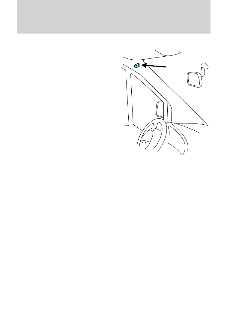
Microphone
Your vehicle has a microphone
located in the A-pillar for the
hands-free phone features and voice
commands.
To mute the microphone: During
an active call, press < or > on the
audio system. Press again to
un-mute and return to normal
function.
Voice commands
Voice commands allow you to speak commands to the system while
enabling you to keep your focus on the road. As you work through a
voice session, the system will prompt you with a tone each time the
system is ready to proceed.
Name tag feature: This system has a name tag feature which allows
you assign name tags to items such as a favorite radio station or personal
phone contact. You can store up to 20 name tags per function.
Note: There are some voice command ’short cuts’ available which allow
you to speak those commands directly without having to follow the
complete command menu.
28
Page 29
CD player voice commands
Press the VOICE button on the
stalk. After the tone, say, “CD
player” and then any of the
following commands:
Entertainment Systems
E
IC
O
V
VOL
SEEK
E
D
O
M
VOL
• Play • Track
• Shuffle all • Shuffle folder
• Shuffle off • Repeat folder
1
2
2
• Repeat track • Repeat off
• Help
1
Can be used as a shortcut.
2
Only available as a voice command if the CD contains audio data files
such as .mp3 or .wma.
Note: You can select any track number between 1–99. You can also list
numbers individually, such as, “two, four, five” for track 245.
Radio voice commands
Press the VOICE button on the stalk. After the tone, say, “Radio” and
then any of the following commands:
• AM • FM
• Tune name
1
• Delete name
• Delete directory • Play directory
• Store name • Play
• Help
1
Can be used as a shortcut. This allows you to call up a stored radio
station.
29
Page 30

Entertainment Systems
Phone voice commands
Press the VOICE button on the stalk. After the tone, say, “Phone” and
then any of the following commands:
• Mobile name
• Dial number
1
1
• Dial name
• Delete name
• Delete directory • Play directory
• Store name* • Redial
• Accept calls • Reject calls
• Help
1
Can be used as a shortcut.
Store name: When you say, “Store name”, the system will ask you for
the name. Say the name. The system will then ask you for the number
associated with that name. Say the number.
Delete name: Allows you to delete a stored radio station.
Delete directory: Allows you to delete all stored stations at once.
Play directory: Allows you to let the system tell you of all the stored
radio stations.
Note: Using the system with the engine off will drain the battery.
Phone features
Phonebook
If your Bluetooth enabled cellular phone supports the feature, you can
download your cell phone’s phone book to the Bluetooth system.
Depending on your phone book entry, different categories may be
displayed in the audio display, such as:
•
or ’Phone’
• or ’Mobile’ or ’M’
•
•
•
or ’Home’ or ’H’
or ’Office’ or ’O’
or ’Fax’ or ’F’
1
1
30
Page 31

Entertainment Systems
Making a call using voice commands
To make a hands-free call using your system:
1. Press the VOICE button on the stalk.
2. When the tone sounds, say, “Phone”. The system will confirm you are
in phone mode.
3. Say, “Dial name” or “Dial number”.
4. When prompted, say the desired name or phone number. The system
will ask you to confirm. If you confirm, the call will be placed. Otherwise,
the call will be cancelled.
Making a call using your phone book entries
To access your phone book entries via Bluetooth:
1. Press the
2. Press MENU repeatedly until PHONEBOOK appears in the display.
3. Press the SEEK switch on the back of the stalk to scroll through all
possible listings.
Note: Press and hold SEEK to advance to the next letter in the
alphabet.
4. When the desired contact appears in the display, press
the call.
Ending a call
At any time, you can end an active call by pressing
system.
To exit phone mode (and end an active call if present), CD, AM/FM,
VOL ON/OFF, or
button on your audio system.
to initiate
on the audio
on the audio system.
Answering an incoming call
Accept the call by pressing the
call will be transferred to hands-free mode.
Ignore the call by doing nothing.
Reject the call by pressing CD, AM/FM or VOL/ON/OFF on the audio
system.
Answering a second incoming call
If another calls comes in while you are already on an active call, you will
hear a beep. You have the choice to end your current call and accept the
incoming call.
button on the audio system. The
31
Page 32

Entertainment Systems
To accept the incoming call, press the button on the audio
system.
To reject the incoming call, by pressing CD or AM/FM on the audio
system.
Redialing a number
To redial a number:
1. Press
2. Press MENU repeatedly to cycle through CALL OUT, CALL IN,
MISSED, INCOMING or OUTGOING appears in the display.
3. When the desired selection appears in the display, press < or > to
access the desired number.
4. When the desired number appears in the display, press
system to initiate the call.
To redial a number using voice commands:
1. Press VOICE on the stalk.
2. After the tone, say, “Phone”.
3. When prompted, say, “Redial”. The system will attempt to redial the
last number.
Changing the active phone
With your Bluetooth system, you can pair (bond) and save up to six
phones. At any time, you can choose to make another one of your saved
phones the ’active’ phone with which the system will connect. To select a
another paired (bonded) phone as your active phone:
1. Press
2. Press MENU repeatedly until ACTIVE appears in the display.
3. Press < or > on the audio system to scroll through the list of paired
(bonded) phones.
4. When the desired selection appears in the display, press MENU.
Deleting a phone
A paired (bonded) phone can be deleted from the system at any time as
long as the phone is not involved in an active call. To delete a phone
from the system:
1. Press
2. Press MENU repeatedly until DEBOND appears in the display.
32
on the audio system to enter the phone menu.
for the
on the audio system to enter the phone menu.
on the audio system to enter the phone menu.
Page 33

Entertainment Systems
3. Press < or > on the audio system to scroll through the list of paired
(bonded) phones.
4. When the desired selection appears in the display that you would like
to delete, press MENU.
GENERAL AUDIO INFORMATION
Radio frequencies:
AM and FM frequencies are established by the Federal Communications
Commission (FCC) and the Canadian Radio and Telecommunications
Commission (CRTC). Those frequencies are:
AM: 530, 540–1700, 1710 kHz
FM: 87.7, 87.9–107.7, 107.9 MHz
Radio reception factors:
There are three factors that can affect radio reception:
• Distance/strength: The further you travel from an FM station, the
weaker the signal and the weaker the reception.
• Terrain: Hills, mountains, tall buildings, power lines, electric fences,
traffic lights and thunderstorms can interfere with your reception.
• Station overload: When you pass a broadcast tower, a stronger signal
may overtake a weaker one and play while the weak station frequency
is displayed.
CD/CD player care
Do:
• Handle discs by their edges only.
(Never touch the playing
surface).
• Inspect discs before playing.
• Clean only with an approved CD
cleaner.
33
Page 34

Entertainment Systems
• Wipe discs from the center out.
Don’t:
• Expose discs to direct sunlight or heat sources for extended periods
of time.
• Clean using a circular motion.
CD units are designed to play commercially pressed 4.75 in
(12 cm) audio compact discs only. Due to technical
incompatibility, certain recordable and re-recordable compact
discs may not function correctly when used in Ford CD players.
Do not use any irregular shaped
CDs or discs with a scratch
protection film attached.
CDs with homemade paper
(adhesive) labels should not be
inserted into the CD player as
the label may peel and cause the
CD to become jammed. It is
recommended that homemade
CDs be identified with
permanent felt tip marker rather
than adhesive labels. Ballpoint pens may damage CDs. Please
contact your authorized dealer for further information.
Audio system warranty and service
Refer to the Warranty Guide/Customer Information Guide for audio
system warranty information. If service is necessary, see your dealer or
qualified technician.
34
Page 35

Climate Controls
MANUAL HEATING AND AIR CONDITIONING SYSTEM
1. Temperature control: Controls the temperature of the airflow in the
vehicle. For optimum defrosting performance, set the dial to the defrost
symbol
2. Air flow selections: Controls the direction of the airflow in the
vehicle. See the following for a brief description on each control setting:
: Distributes air through the instrument panel vents.
: Distributes air through the instrument panel vents and floor vents.
: Distributes air through the floor vents. Note: You may notice a
small amount of air flowing from the demister and defroster vents.
: Distributes air through the windshield defroster vents, demisters
and floor vents.
: Distributes outside air through the windshield defroster and
demister vents. Can be used to clear thin ice or fog from the windshield.
To exit
3.
the vehicle. For optimum defrosting performance, set the dial to at least
the 3 or 4 position near the
.
select another mode.
Fan speed adjustment: Controls the volume of air circulated in
(defrost) symbol.
35
Page 36

Climate Controls
4. Recirculated air: Press to activate/deactivate air recirculation
in the vehicle cabin. Recirculated air may reduce the amount of time
required to cool down the interior of the vehicle and may also help
reduce undesired odors from reaching the interior of the vehicle.
Recirculated air will not function in
5. A/C: Press to activate/deactivate air conditioning. Use with
recirculated air to improve cooling performance and efficiency. Engages
automatically in
Operating tips
• To reduce fog build up on the windshield during humid weather,
select
near the (defrost) symbol. Also, set the temperature setting to
the defrost symbol
• To reduce humidity build up inside the vehicle, do not drive with the
system off or with
• Do not put objects under the front seats that will interfere with the
airflow to the back seats.
• Remove any snow, ice or leaves from the air intake area at the base of
the windshield.
• To improve the time to reach comfort in hot weather, drive with the
windows slightly open for 2-3 minutes after start up or until the
vehicle has been “aired out.”
During extreme high ambient temperatures when idling stationary for
extended periods of time in gear, it is recommended to run the A/C in
the max A/C mode, reduce blower fan speed from the highest setting and
put the vehicle’s transmission into the P (Park) gear position to continue
to receive cool air from your A/C system.
For maximum cooling performance, select max A/C by doing the
following:
1. Select the coolest temperature setting.
2. Select recirculation air mode.
3. Set the fan to the highest speed initially. As the interior starts to cool
down, adjust the fan speed to maintain comfort and/or switch from
recirculated air to outside air mode.
(defrost) and set the fan speed dial to the 3 or 4 position
(defrost).
during cooler weather.
(recirculated air) engaged and A/C off.
(defrost).
36
Page 37

Climate Controls
To aid in side window defogging/demisting in cold weather:
1. Select
2. Select A/C.
3. Adjust the temperature control to maintain comfort.
4. Set the fan speed to the highest setting.
5. Direct the outer instrument panel vents towards the side windows.
To increase airflow to the outer instrument panel vents, close the vents
located in the middle of the instrument panel.
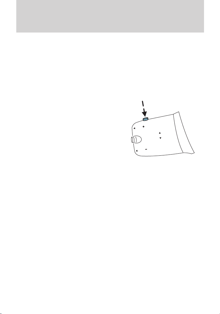
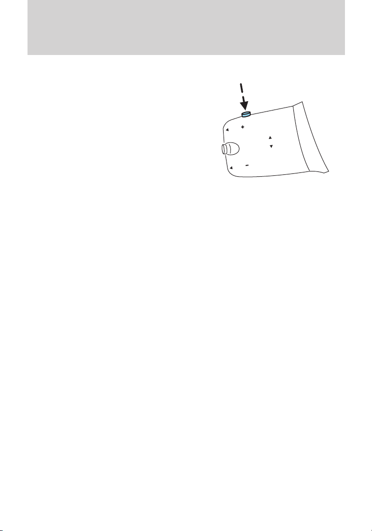
REAR WINDOW DEFROSTER (IF EQUIPPED) / HEATED MIRRORS (IF EQUIPPED)
The rear defroster control is located
on the instrument panel above the
radio and works to clear the rear
windows of fog and thin ice.
The ignition must be on to operate the rear window defroster.
Press
button will illuminate when active. The rear window defroster turns off
automatically after a predetermined amount of time, if a low battery
condition is detected or when the ignition is turned off. To manually turn
off the rear window defroster at any time, press the control again.
If your vehicle is equipped with heated mirrors, this button will activate
them. Refer to Exterior mirrors in the Driver Controls chapter.
Do not use razor blades or other sharp objects to clean the inside
of the rear window or to remove decals from the inside or the
rear window. This may cause damage to the heated grid lines and
will not be covered by your warranty.
.
to turn the rear window defroster on. An indicator light on the
37
Page 38

Lights
HEADLAMP CONTROL
Turns the lamps off.
Turns on the parking lamps,
instrument panel lamps, license
plate lamps and tail lamps.
Turns the headlamps on.
Rear fog lamp
The headlamp control also operates
the rear fog lamp. The rear fog lamp
can only be turned on when the
headlamp control is in
the
Pull the headlamp control towards you to turn the rear fog lamp on. The
fog lamp indicator light
Note: Do not use the rear fog lamp when it is raining or snowing and
visibility is more than 165 feet (50m).
position.
will illuminate.
Daytime running lamps (DRL) (if equipped)
Turns the headlamps on with a reduced output.
To activate:
• the ignition must be in the on position and
• the headlamp control is in the off or parking lamp position.
WARNING: Always remember to turn on your headlamps at
dusk or during inclement weather. The Daytime Running Lamp
(DRL) system does not activate the tail lamps and generally may not
provide adequate lighting during these conditions. Failure to activate
your headlamps under these conditions may result in a collision.
38
Page 39

High beams
Pull the lever toward you to the
second detent to activate the high
beams. Pull the lever again toward
you to the second detent to
deactivate.
Flash to pass
Pull the lever toward you to the first
detent to activate flash to pass, and
release to deactivate.
Lights
PANEL DIMMER CONTROL
Use to adjust the brightness of the
instrument panel and all applicable
switches in the vehicle during
headlamp and parking lamp
operation.
Move the control from left to right
to increase the brightness. Move the control from right to left to reduce
the brightness.
AIMING THE HEADLAMPS
The headlamps on your vehicle are properly aimed at the assembly plant.
If your vehicle has been in an accident, the alignment of your headlamps
should be checked by your authorized dealer.
39
Page 40

Lights
VERTICAL AIM ADJUSTMENT
1. Park the vehicle directly in front of a wall or screen on a level surface,
approximately 25 feet (7.6 meters) away.
• (1) 8 feet (2.4 meters)
• (2) Center height of lamp to
ground
• (3) 25 feet (7.6 meters)
• (4) Horizontal reference line
2. Measure the height from the
center of your headlamp to the
ground and mark an 8 foot
(2.4 meter) horizontal reference line
on the vertical wall or screen at this
height (a piece of masking tape works well).
3. Turn on the low beam headlamps to illuminate the wall or screen and
open the hood.
4. On the wall or screen you will
observe an area of high intensity
light. The top of the high intensity
area should touch the horizontal
reference line. If not, the beam will
need to be adjusted.
5. Locate the vertical adjuster on
each headlamp, then use a Phillips
#2 screwdriver or 10 mm
wrench/socket to adjust the
headlamp up or down.
6. Close the hood and turn off the
lamps.
HORIZONTAL AIM IS NOT REQUIRED FOR THIS VEHICLE AND IS
NON-ADJUSTABLE.
40
Page 41

Lights
TURN SIGNAL CONTROL
• Push down to activate the left
turn signal.
• Push up to activate the right turn
signal.
INTERIOR LAMPS
Dome lamps
The dome lamp is equipped with a
control switch that will illuminate
when:
• the doors are closed and the
switch is in the right position.
• the switch is in the middle
position and any door is open.
When the dome lamp switch is in the left position, it will not illuminate
when you open the doors.
Reading lamps (if equipped)
The reading lamps are operated by
separate on/off controls.
Theater dimming: The dome lamp
dims about 20 seconds after the
doors are closed.
Approach lamps (if equipped)
The approach lamps will turn on and off automatically when you open
and close the doors. If you unlock the doors with the remote control,
they will come on. They will go off automatically after a short time.
41
Page 42

Lights
BULB REPLACEMENT
Lamp assembly condensation
Exterior lamps are vented to accommodate normal changes in pressure.
Condensation can be a natural by-product of this design. When moist air
enters the lamp assembly through the vents, there is a possibility that
condensation can occur when the temperature is cold. When normal
condensation occurs, a thin film of mist can form on the interior of the
lens. The thin mist eventually clears and exits through the vents during
normal operation. Clearing time may take as long as 48 hours under dry
weather conditions.
Examples of acceptable condensation are:
• Presence of thin mist (no streaks, drip marks or droplets)
• Fine mist covers less than 50% of the lens
Examples of unacceptable moisture (usually caused by a lamp water
leak) are:
• Water puddle inside the lamp
• Large water droplets, drip marks or streaks present on the interior of
the lens
Take your vehicle to dealer for service if any of the above conditions of
unacceptable moisture are present.
Using the right bulbs
Replacement bulbs are specified in the chart below. Headlamp bulbs
must be marked with an authorized “D.O.T.” for North America to ensure
lamp performance, light brightness and pattern and safe visibility. The
correct bulbs will not damage the lamp assembly or void the lamp
assembly warranty and will provide quality bulb burn time.
Function Trade number
Headlamps H13
Turn lamp indicator (front) 3457NAK
Turn lamp indicator (rear) WY21W
Side marker lamp W5W LL
Side repeater lamp 194NA
Brake and tail lamps W21/5W
Backup lamp W21W
License plate lamp W5W LL
High-mount brake lamp LED
To replace all instrument panel lights - see your authorized dealer
42
Page 43

Replacing interior bulbs
Check the operation of all bulbs frequently.
Replacing front dome lamps
1. Make sure the headlamp switch is
in the off position.
2. Switch off the interior lamps.
3. Pry out the light assembly with a
flat screwdriver.
Install in reverse order.
Replacing rear dome lamps
1. Make sure the headlamp switch is
in the off position.
2. Switch off the interior lamps.
3. Pry out the light assembly with a
flat screwdriver.
Lights
Install in reverse order.
43
Page 44

Lights
Replacing reading bulbs
1. Open the reading lamp assembly.
2. Pull the bulb straight out and
replace it.
3. After the bulb has been replaced,
close the lamp assembly.
Install in reverse order.
Replacing exterior bulbs
Check the operation of all bulbs frequently.
Replacing headlamp bulbs
1. Make sure the headlamp control
is in the off position and open the
hood.
2. Pull off the bulb cap.
3. Disconnect electrical connector
from the bulb.
4. Twist off the bulb retainer ring by
turning it counterclockwise.
Install in reverse order.
WARNING: Handle a halogen headlamp bulb carefully and keep
out of children’s reach. Grasp the bulb by only its plastic base
and do not touch the glass. The oil from your hand could cause the
bulb to break the next time the headlamps are operated.
Note: If the bulb is accidentally touched, it should be cleaned with
rubbing alcohol before being used.
44
Page 45

Replacing front parking lamp bulbs
1. Make sure the headlamp control
is in the off position.
2. Turn the cover counterclockwise
and remove it.
3. Remove the bulb and the bulb
socket.
4. Pull the bulb straight out.
Lights
Install in reverse order.
45
Page 46

Lights
Replacing front turn signal bulbs
1. Make sure the headlamp control
is in the off position and open the
hood.
2. Remove the bulb socket from the
lamp assembly by turning it
counterclockwise.
3. Pull the bulb straight out of the
socket.
Install in reverse order.
Replacing tail/brake/backup lamps and turn signal bulbs
1. Make sure the headlamp control
is in the off position and then open
the cargo door.
2. Remove the two wing nuts and
gently pull the lamp assembly away
from the vehicle.
46
Page 47

3. Remove the bulb socket from the
lamp assembly by turning it
counterclockwise.
4. Pull the bulb straight out of the
socket.
Install in reverse order.
Lights
47
Page 48

Lights
Replacing front and rear side marker bulbs
1. Make sure the headlamp control
is in the off position and then open
the cargo door.
2. Remove the side marker by gently
prying the lamp assembly away from
the vehicle.
3. Remove the bulb socket from the
lamp assembly by turning it
counterclockwise.
4. Pull the bulb straight out of the
socket.
Install in reverse order.
Replacing side repeater bulbs
1. Make sure the headlamp control
is in the off position.
2. Remove the side repeater by
prying it out from the bottom.
3. Hold the bulb holder and turn it
counterclockwise to remove it.
4. Pull the bulb straight out.
Install in reverse order.
48
Page 49

Replacing high-mount brake lamp bulbs
See your authorized dealer for replacement.
Replacing license plate lamp bulbs
1. Make sure the headlamp control
is in the off position.
2. Remove the lens assembly.
3. Pull the bulb straight out.
Install in reverse order.
Lights
49
Page 50

Driver Controls
MULTI-FUNCTION LEVER
Windshield wiper
Move the lever down for a single
wipe.
For intermittent operation,
move control up one position and
adjust the rotary control to the
desired speed.
For normal operation, move
control up two positions and up
three positions for high speed
wiping.
Windshield washer
To activate the windshield washer, push the windshield washer
control. Release control to stop washer fluid spray. The wipers will
operate for a short time after the wash is turned off.
Note: Do not operate the washer when the washer reservoir is empty.
This may cause the washer pump to overheat. Check the washer fluid
level frequently. Do not operate the wipers when the windshield is dry.
This may scratch the glass, damage the wiper blades and cause the wiper
motor to burn out. Before operating the wiper on a dry windshield,
always use the windshield washer. In freezing weather, be sure the wiper
blades are not frozen to the windshield before operating the wipers.
Rear window wiper/washer (if equipped)
Wiper
Pull the lever towards you for intermittent wiping.
Washer
Pull the lever further to operate the washer. The wiper will operate
for a short time and will activate once more after pausing to clear the
windshield.
Reverse gear wipe
The rear wiper will be activated automatically when shifting into reverse
if the front wiper is activated.
50
Page 51

TILT AND TELESCOPE STEERING COLUMN
Release the locking lever to adjust
the height of the steering wheel and
its distance from the driver.
Return the lever to its original
position to secure the wheel.
WARNING: Never adjust the steering wheel when the vehicle is
moving.
Driver Controls
CENTER CONSOLE
Your vehicle has a variety of console features. These include:
• Cupholders
• Storage area
• Power window switches (if equipped)
WARNING: Use only soft cups in the cupholder. Hard objects
can injure you in a collision.
51
Page 52

Driver Controls
OVERHEAD STORAGE SHELF
The storage shelf above the
windshield can be used for storing
light objects such as safety jackets,
coats, etc.
WARNING: Do not place heavy or hard objects in the overhead
storage, which may fall while driving, and could cause serious
injury.
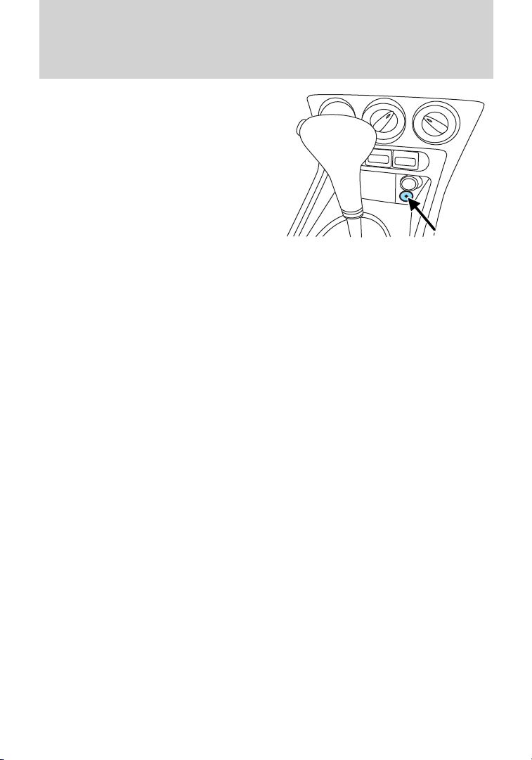
AUXILIARY POWER POINTS (12VDC)
Power outlets are designed for accessory plugs only. Do not insert
any other object in the power outlet as this will damage the
outlet and blow the fuse. Do not hang any type of accessory or
accessory bracket from the plug. Improper use of the power
outlet can cause damage not covered by your warranty.
The auxiliary power point(s) is
located near the transmission shift
lever.
Your vehicle may also include an auxiliary power point located in the
rear cargo area.
Do not use the power point for operating a cigarette lighter element.
To prevent the fuse from being blown, do not use the power point(s)
over the vehicle capacity of 12 VDC/180W. If the power point or cigar
lighter socket is not working, a fuse may have blown. Refer to Fuses and
relays in the Roadside Emergencies chapter for information on
checking and replacing fuses.
52
Page 53

Driver Controls
To have full capacity usage of your power point, the engine is required to
be running to avoid unintentional discharge of the battery. To prevent
the battery from being discharged:
• do not use the power point longer than necessary when the engine is
not running,
• do not leave battery chargers, video game adapters, computers and
other devices plugged in overnight or when the vehicle is parked for
extended periods.
Always keep the power point caps closed when not being used.
POWER WINDOWS (IF EQUIPPED)
WARNING: Do not leave children unattended in the vehicle and
do not let children play with the power windows. They may
seriously injure themselves.
WARNING: When closing the power windows, you should verify
they are free of obstructions and ensure that children and/or
pets are not in the proximity of the window openings.
Press/pull the window switches,
located on the center console near
the cupholders, to open/close the
windows.
One touch down
Allows the driver’s window to open fully without holding the control
down. Press the switch down and release quickly. The window will open
fully. Press it again to stop the window.
53
Page 54

Driver Controls
INTERIOR MIRROR
The interior rear view mirror has two pivot points on the support arm
which lets you adjust the mirror: up, down and from side-to-side.
Push the tab to help reduce glare at
night.
WARNING: Do not adjust the mirror while the vehicle is in
motion.
EXTERIOR MIRRORS
Power side view mirrors (if equipped)
To adjust your mirrors:
1. Rotate the control clockwise to
adjust the right mirror or
counterclockwise to adjust the left
mirror.
2. Move the control in the direction
you wish to tilt the mirror.
3. Return the control to the center position to lock mirrors in place.
Heated side view mirrors (if equipped)
Both mirrors are heated automatically to remove ice, mist and fog when
the rear window defrost is activated.
Do not remove ice from the mirrors with a scraper or attempt to
readjust the mirror glass if it is frozen in place. These actions
could cause damage to the glass and mirrors.
Fold-away mirrors
Pull/push the mirrors in to fold/unfold them.
54
Page 55

Driver Controls
SPEED CONTROL (IF EQUIPPED)
With speed control set, you can maintain a set speed without keeping
your foot on the accelerator pedal.
WARNING: Do not use the speed control in heavy traffic or on
roads that are winding, slippery or unpaved.
Setting speed control
The controls for using your speed
control are located on the steering
wheel.
1. Press ON and release it.
2. Accelerate to the desired speed.
3. Press SET + and release it.
4. Take your foot off the accelerator
pedal.
5. The indicator light on the
instrument cluster will turn on.
RES
SET
Note:
• Vehicle speed may vary momentarily when driving up and down a
steep hill.
• If the vehicle speed increases above the set speed on a downhill, you
may want to apply the brakes to reduce the speed.
• If the vehicle speed decreases more than 10 mph (16 km/h) below
your set speed on an uphill, your speed control will disengage.
Disengaging speed control
To disengage the speed control, depress the brake pedal.
Disengaging the speed control will not erase previous set speed.
55
Page 56

Driver Controls
Resuming a set speed
Press RES and release it. This will
automatically return the vehicle to
the previously set speed.
Increasing speed while using speed control
There are two ways to set a higher
speed:
• Press and hold SET + until you
get to the desired speed, then
release the control. You can also
use the SET + control to operate
the Tap-Up function. Press and
release this control to increase
the vehicle set speed in small
amounts by 1 mph (1.6 km/h).
• Use the accelerator pedal to get to the desired speed. When the
vehicle reaches that speed, press and release the SET + control.
RES
SET
Reducing speed while using speed control
There are two ways to reduce a set
speed:
• Press and hold – until you get to
the desired speed, then release
the control. You can also use the
– control to operate the
Tap-Down function. Press and
release – to decrease the vehicle
set speed in small amounts by
1 mph (1.6 km/h).
56
Page 57

Driver Controls
• Depress the brake pedal until the
desired vehicle speed is reached,
press SET +.
Turning off speed control
Press OFF.
Note: When you turn off the speed
control or the ignition, your speed
control set speed memory is erased.
STEERING WHEEL CONTROLS (IF EQUIPPED)
The following functions can be operated with the steering wheel
controls:
Volume
• Volume up: Press the top button
on the back of the remote
control.
• Volume down: Press the bottom
button on the back of the remote
control.
VOL
VOL
RES
SET
E
C
I
O
V
K
E
E
S
E
D
O
M
57
Page 58

Driver Controls
Seek
Move the SEEK switch up or down:
• In radio mode, this will locate the
next radio station up or down the
frequency band.
• In CD mode, it will select the
next or previous track.
Mode
Briefly press the button on the side:
• In radio mode, this will locate the
next pre-set radio station.
• In CD mode, this will select the
next CD when equipped with a
CD changer.
• In all modes to abort a traffic
message during broadcasting
Press and hold the button on the side:
• In radio mode, to change the band (AM, FM).
E
IC
O
V
L
O
V
K
E
E
S
E
D
O
M
L
O
V
VOICE
L
O
V
K
E
E
S
MODE
L
O
V
58
Page 59

DUAL REAR DOORS
Open the right hand door first from
either the outside (1) or inside (2)
the vehicle.
Open the left hand door second by
squeezing the handle to unlatch the
door and pulling it open.
Driver Controls
12
59
Page 60

Driver Controls
Note: The dual rear doors should be closed before driving your vehicle.
Leaving the doors open could cause serious damage to them and their
components. The left door must be closed first.
Opening the doors fully
Push the yellow button located on
the door and swing it open. The
check arms will automatically
re-engage when the doors are
closed.
60
Page 61

Locks and Security
KEYS
The key operates all locks on your vehicle. You should always carry a
second key with you in a safe place in case you require it in an
emergency.
If your vehicle is equipped with the SecuriLock™ Passive Anti-theft
system, your keys are electronically coded to your vehicle; using a
non-coded key will not permit your vehicle to start. If you lose your
dealer supplied keys, replacement keys are available through your
authorized dealer.
Central unlocking/locking
• To unlock the passenger doors, turn the key towards the front of the
vehicle.
• To lock the all doors, turn the key towards the rear of the vehicle.
CHILDPROOF DOOR LOCKS
• When these locks are set, the
sliding doors cannot be opened
from the inside.
• The sliding doors can be opened
from the outside when the doors
are unlocked.
The childproof locks are located on
rear edge of each sliding door and
must be set separately for each
door. Setting the lock for one door
will not automatically set the lock
for both doors.
• Insert the key and turn to the
lock position to engage the
childproof locks.
• Insert the key and turn to the
unlock position to disengage the
childproof locks.
61
Page 62

Locks and Security
REMOTE ENTRY SYSTEM (IF EQUIPPED)
This device complies with part 15 of the FCC rules and with RSS-210 of
Industry Canada. Operation is subject to the following two conditions:
(1) This device may not cause harmful interference, and (2) This device
must accept any interference received, including interference that may
cause undesired operation.
Remote entry receiver certification numbers
Country Part Label/Type Approval
Canada SIEMENS VDO 5WK4 7899
IC: 267T - 5WK47899
USA SIEMENS VDO 5WK4 7899
FCC ID: KR55WK47899
Changes or modifications not expressly approved by the party
responsible for compliance could void the user’s authority to
operate the equipment.
The typical operating range for your remote entry transmitter is
approximately 33 feet (10 meters). A decrease in operating range could
be caused by:
• weather conditions,
• nearby radio towers,
• structures around the vehicle, or
• other vehicles parked next to
your vehicle.
The remote entry system allows you
to lock or unlock all vehicle doors
and cargo door without a key.
Note: The lock and unlock buttons
work only when the ignition is the
off position. The cargo door button
works when the ignition is any
position.
If there are problems with the
remote entry system, make sure to take ALL remote entry
transmitters with you to the authorized dealer in order to aid in
troubleshooting the problem.
62
Page 63

Locks and Security
Two-step door unlocking
• Press
• Within three seconds, press and release again to unlock all the
doors.
Note: The interior lamps will illuminate if the control on the overhead
lamp is not set to the off position.
One-step door unlocking
If the one step door unlocking feature is activated, press
once to unlock all the doors. Note: The interior lamps will illuminate
(refer to the Illuminated entry feature later in this section), if the
control on the overhead lamp is not set to the off position.
Switching from two step to one step door unlocking
Your vehicle comes with two step unlocking enabled. With the vehicle
locked, unlocking can be switched between two step and one step door
unlocking by pressing and holding both the
simultaneously on the remote entry transmitter for approximately four
seconds and release. The turn signal lamps will flash twice to indicate
that the vehicle has switched to one step unlocking. Repeat the
procedure to switch back to two-step unlocking.
Unlocking cargo doors
• Press
Ensure that the cargo doors are closed and latched before driving your
vehicle. Failure to properly latch the cargo doors may cause objects to
fall out.
and release to unlock the passenger doors.
and release
and buttons
to unlock the cargo doors.
Locking the doors
1. Press and release to lock all the doors. If all doors are closed the
turn signal lamps will flash twice.
63
Page 64

Locks and Security
Replacing the battery
The remote entry transmitter uses one coin type three-volt lithium
battery CR2032 or equivalent.
To replace the battery:
1. Carefully separate the transmitter
unit from the key using a flat object
(e.g. a screwdriver) at the recess on
the back.
2. Open the transmitter unit by
separating the retaining clips on the
sides with the flat object.
3. Remove the old battery.
Note: Please refer to local
regulations when disposing of
transmitter batteries.
4. DO NOT TAKE THE PLASTIC
COVER AND CIRCUIT BOARD OFF
THE FRONT HOUSING OF THE
REMOTE ENTRY TRANSMITTER.
5. Do not wipe off any grease on the
battery terminals or the back
surface of the circuit board.
6. Insert the new battery. The positive + terminal should face upwards.
Press the battery down to ensure that the battery is fully seated in the
battery housing cavity.
64
Page 65

Locks and Security
7. Snap the two halves back together.
Note: Replacement of the battery will not cause the remote transmitter
to become deprogrammed from your vehicle. The remote transmitter
should operate normally after battery replacement.
Replacing lost remote entry transmitters
If you would like to have your remote entry transmitter reprogrammed
because you lost one, or would like to buy additional remote entry
transmitters, you can either reprogram them yourself, or take all
remote entry transmitters to your authorized dealer for
reprogramming.
How to reprogram your remote entry transmitters
You must have all remote entry transmitters (maximum of four)
available before beginning this procedure. If all remote entry transmitters
are not present during the programming procedure, the transmitters that
are not present during programming will no longer operate the vehicle.
Note: Ensure the brake pedal is not depressed during this sequence.
To reprogram the remote entry transmitters:
1. Ensure the vehicle is electronically unlocked.
2. Put the key in the ignition.
3. Turn the key from the O (off)
position to II (on).
4. Cycle eight times rapidly (within
10 seconds) between the O (off)
position and II (on).
Note: The eighth turn must end in
the II (on) position.
5. The doors will lock, then unlock,
to confirm that the programming mode has been activated.
6. Within 20 seconds press any button on the remote entry transmitter.
Note: If more than 20 seconds have passed you will need to start the
procedure over again.
7. The doors will lock, then unlock, to confirm that this remote entry
transmitter has been programmed.
8. Repeat Step 6 to program each additional remote entry transmitter.
9. Turn the ignition to the O (off) position after you have finished
programming all of the remote entry transmitters.
10. The doors will lock, then unlock, to confirm that the programming
mode has been exited.
65
Page 66

Locks and Security
Illuminated entry
The interior lamps illuminate when the remote entry system is used to
unlock the door(s).
The illuminated entry system will turn off the interior lights if:
• the ignition switch is turned to the on position, or
• the remote transmitter lock control is pressed, or
• after 25 seconds of illumination.
The dome lamp control (if equipped) must not be set to the off position
for the illuminated entry system to operate.
The inside lights will not turn off if:
• they have been turned on with the dome lamp control, or
• any door is open.
SECURILOCK™ PASSIVE ANTI-THEFT SYSTEM (IF EQUIPPED)
SecuriLock™ passive anti-theft system is an engine immobilization
system. This system is designed to help prevent the engine from being
started unless a coded key programmed to your vehicle is used. The
use of the wrong type of coded key may lead to a “no-start” condition.
Your vehicle comes with two coded keys; additional coded keys may be
purchased from your authorized dealer. The authorized dealer can
program your spare keys to your vehicle or you can program the keys
yourself. Refer to Programming spare keys for instructions on how to
program the coded key.
Note: The SecuriLock™ passive anti-theft system is not compatible with
non-Ford aftermarket remote start systems. Use of these systems may
result in vehicle starting problems and a loss of security protection.
Note: Large metallic objects, electronic devices that are used to
purchase gasoline or similar items, or a second coded key on the same
key chain may cause vehicle starting issues. You need to prevent these
objects from touching the coded key while starting the engine. These
objects will not cause damage to the coded key, but may cause a
momentary issue if they are too close to the key when starting the
engine. If a problem occurs, turn the ignition off, remove all objects on
the key chain away from the coded key and restart the engine.
Note: Do not leave a duplicate coded key in the vehicle. Always
take your keys and lock all doors when leaving the vehicle.
66
Page 67

Locks and Security
Anti-theft indicator
The anti-theft indicator is located in the instrument cluster.
• When the ignition is in the off
position, the indicator will flash
briefly to indicate the
SecuriLock™ system is
functioning as a theft deterrent.
The indicator light will stop flashing after approximately 10 seconds.
• When the ignition is in the on position, the indicator will glow for
three seconds, then turn off, to indicate normal system functionality.
If a problem occurs with the SecuriLock™ system, the indicator will flash
rapidly or glow steadily when the ignition is in the on position. If this
occurs, turn the ignition off then back to on to make sure there was no
electronic interference with the programmed key. If the vehicle doesn’t
start, try to start it with the 2nd programmed key and if successful
contact your authorized dealership for key replacement. If the indicator
still flashes rapidly or glows steadily, and the vehicle will not start,
contact your authorized dealer as soon as possible for service.
Automatic arming
The vehicle is armed immediately after switching the ignition to the off
position.
Automatic disarming
Switching the ignition to the on position with a coded key disarms the
vehicle.
Replacement keys
If your keys are lost or stolen and you don’t have an extra coded key,
you will need to have your vehicle towed to an authorized dealer. The
key codes need to be erased from your vehicle and new coded keys will
need to be programmed.
Replacing coded keys can be very costly. Store an extra programmed key
away from the vehicle in a safe place to help prevent any
inconveniences. Please visit an authorized dealer to purchase additional
spare or replacement keys.
Programming spare keys
You can program your own coded keys to your vehicle. Please read and
understand the entire procedure before you begin.
67
Page 68

Locks and Security
The process for programming Securilock™ keys is independent of the
process for programming Remote Entry Transmitters. If your vehicle is
fitted with Securilock™ and Remote Entry, you must perform both
learning procedures in order to program both the Immobilizer and
Remote Locking functions of the key fob.
Tips:
• A maximum of eight keys can be coded to your vehicle.
• Only use SecuriLock™ keys.
• You must have two previously programmed coded keys (keys that
already operate your vehicle’s engine) and the new unprogrammed
key(s) readily accessible.
• If two previously programmed coded keys are not available, you must
take your vehicle to your authorized dealer to have the spare key(s)
programmed.
1. Insert a previously programmed
coded key into the ignition.
2. Turn the ignition from the O (off)
position to the II (on) position.
Keep the ignition in the II (on)
position for at least one second, but
no more than 10 seconds.
3. Turn the ignition to the O (off)
position.
4. Remove the previously programmed coded key from the ignition.
5. After three seconds but within 10 seconds of removing the previously
programmed coded key, insert the other previously programmed coded
key into the ignition.
6. Turn the ignition from the O (off) position to the II (on) position.
Keep the ignition in the II (on) position for at least one second but not
more than 10 seconds.
7. Turn the ignition to the O (off) position.
8. Remove the previously programmed coded key from the ignition.
9. After three seconds but within twenty seconds of removing the
previously programmed coded key, insert the unprogrammed key
(new/valet key) into the ignition.
10. Turn the ignition from the O (off) position to the II (on) position.
Keep the ignition in the II (on) position for at least one second, but no
more than 10 seconds.
68
Page 69

Locks and Security
11. Your new, unprogrammed key is now programmed.
If the key has been successfully programmed it will start the vehicle’s
engine and the theft indicator light will illuminate for three seconds and
then go out.
If the key was not successfully programmed, it will not start your
vehicle’s engine and the theft indicator light will flash on and off, or stay
on for more than three seconds. If failure repeats, bring your vehicle to
your authorized dealer to have the new key(s) programmed.
To program additional new unprogrammed key(s), repeat this procedure
from Step 1 for each additional key.
69
Page 70

Seating and Safety Restraints
SEATING
WARNING: Reclining the seatback can cause an occupant to
slide under the seat’s safety belt, resulting in severe personal
injuries in the event of a collision.
WARNING: Do not pile cargo higher than the seatbacks to
reduce the risk of injury in a collision or sudden stop.
WARNING: Before returning the seatback to its original
position, make sure that cargo or any objects are not trapped
behind the seatback. After returning the seatback to its original
position, pull on the seatback to ensure that it has fully latched. An
unlatched seat may become dangerous in the event of a sudden stop or
collision.
Adjustable head restraints
Your vehicle is equipped with front row outboard head restraints that are
vertically adjustable.
WARNING: To minimize the risk of neck injury in the event of a
crash, the driver and passenger occupants should not sit in
and/or operate the vehicle, until the head restraint is placed in its
proper position. The driver should never adjust the head restraint
while the vehicle is in motion.
The adjustable head restraints
consist of:
• a trimmed energy absorbing foam
and structure (1),
• two steel stems (2),
• a guide sleeve lock/release button
(3),
• and a guide sleeve with a smaller
button for removing the head
restraint (4).
70
Page 71

Seating and Safety Restraints
To adjust the head restraint, do the following:
1. Adjust the seatback to an upright driving/riding position.
2. Raise the head restraint by
pulling up on the head restraint.
3. Lower the head restraint by
pressing and holding the guide
sleeve lock/release button and
pushing down on the head restraint.
Properly adjust the head restraint so that the top of the head restraint is
even with the top of your head and positioned as close as possible to the
back of your head. For occupants of extremely tall stature, adjust the
head restraint to its full up position.
WARNING: The adjustable head restraint is a safety device.
Whenever possible it should be installed and properly adjusted
when the seat is occupied.
71
Page 72

Seating and Safety Restraints
To remove the adjustable head restraint, do the following:
1. Pull up the head restraint until it
reaches the highest adjustment
position.
2. Use a push tool, such as a key, to
press the small button located on
the side of the guide sleeve and, at
the same time, press the
lock/release button, then pull the
head restraint upward.
To reinstall the adjustable head restraint, do the following:
1. Insert the two stems into the
guide sleeve collars.
2. Push the head restraint down
until it locks.
Properly adjust the head restraint so that the top of the head restraint is
even with the top of your head and positioned as close as possible to the
back of your head. For occupants of extremely tall stature, adjust the
head restraint to its full up position.
72
Page 73

Seating and Safety Restraints
WARNING: To minimize the risk of neck injury in the event of a
crash, head restraints must be installed properly.
Adjusting the front manual seat
WARNING: Never adjust the driver’s seat or seatback when the
vehicle is moving.
WARNING: Always drive and ride with your seatback upright
and the lap belt snug and low across the hips.
Lift handle to move seat forward or
backward.
Rotate the control to adjust
seatback.
73
Page 74

Seating and Safety Restraints
Move the front control to raise or
lower the seat cushion.
Using the manual lumbar support
The lumbar support control is
located on the in-board side of the
seatback.
Turn the lumbar support control
clockwise for more support.
Turn the lumbar support
counter-clockwise for less support.
Using the armrest (if equipped)
Move the armrest up or down. You
can also move it all the way up to
stow it on the side of the seatback.
REAR SEATS
Second row adjustable head restraints
Your vehicle is equipped with second row outboard head restraints that
are vertically adjustable.
74
Page 75

Seating and Safety Restraints
WARNING: To minimize the risk of neck injury in the event of a
crash, the driver and passenger occupants should not sit in
and/or operate the vehicle, until the head restraint is placed in its
proper position. The driver should never adjust the head restraint
while the vehicle is in motion.
The adjustable head restraints
consist of :
• a trimmed energy absorbing foam
and structure (1),
• two steel stems (2),
• a guide sleeve adjust release
button (3),
• and a red guide sleeve
unlock/remove button (4).
To adjust the head restraint, do the following:
1. Adjust the seatback to an upright driving/riding position.
2. Raise the head restraint by
pulling up on the head restraint.
3. Lower the head restraint by
pressing and holding the guide
sleeve adjust release button and
pushing down on the head restraint.
75
Page 76

Seating and Safety Restraints
Properly adjust the head restraint so that the top of the head restraint is
even with the top of your head and positioned as close as possible to the
back of your head. For occupants of extremely tall stature, adjust the
head restraint to its full up position.
WARNING: The adjustable head restraint is a safety device.
Whenever possible it should be installed and properly adjusted
when the seat is occupied.
To remove the adjustable head restraint, do the following:
1. Pull up the head restraint until it
reaches the highest adjustment
position.
2. Simultaneously press and hold
both the adjust/release button and
the unlock/remove button, then pull
up on the head restraint.
76
Page 77

Seating and Safety Restraints
To reinstall the adjustable head restraint, do the following:
1. Insert the two stems into the
guide sleeve collars.
2. Push the head restraint down
until it locks.
Properly adjust the head restraint so that the top of the head restraint is
even with the top of your head and positioned as close as possible to the
back of your head. For occupants of extremely tall stature, adjust the
head restraint to its full up position.
WARNING: To minimize the risk of neck injury in the event of a
crash, head restraints must be installed properly.
Folding down the rear seat
One or both rear seatbacks can be folded down to provide additional
cargo space.
To lower a single seatback:
1. Remove the head restraint(s).
Refer to Second row adjustable
head restraints earlier in this
chapter.
Note: Place the head restraint
underneath the back of the front
seat for storage.
2. Pull down the lever on the side of
the seat back.
3. Push the seatback forward.
77
Page 78

Seating and Safety Restraints
To lower both seatbacks:
1. Remove all head restraints. Refer
to Adjustable rear head restraints
in this chapter.
Note: Place the head restraint
underneath the back of the front
seat for storage.
2. Pull the levers on the side of the
seatback.
3. Fold the seatback forward.
To place the seat in the tumble position:
4. Pull the release straps up.
5. Fold the seat forwards until the
lever is automatically locked and
you hear a click.
When raising the seatback(s), make
sure the lever is locked and you
hear the seat latch into place.
78
Page 79

Seating and Safety Restraints
Returning the seat to the upright position
WARNING: Before returning the seatback to its original
position, make sure that cargo or any objects are not trapped
behind the seatback. After returning the seatback to its original
position, pull on the seatback to ensure that it has fully latched. An
unlatched seat may become dangerous in the event of a sudden stop or
collision.
1. Pull down on the locking lever.
2. Fold the seat down.
3. Raise the seatback.
4. Install all head restraints.
5. Ensure that the red indicator is in
the locked position.
• Locked
79
Page 80

Seating and Safety Restraints
• Unlocked
SAFETY RESTRAINTS
Personal Safety System姞
The Personal Safety System威 provides an improved overall level of
frontal crash protection to front seat occupants and is designed to help
further reduce the risk of airbag-related injuries. The system is able to
analyze different occupant conditions and crash severity before activating
the appropriate safety devices to help better protect a range of
occupants in a variety of frontal crash situations.
Your vehicle’s Personal Safety System威 consists of:
• Driver and passenger dual-stage airbag supplemental restraints.
• Front safety belts with pretensioners, energy management retractors,
and safety belt usage sensors.
• Driver’s seat position sensor.
• Two front crash severity sensors.
• Front passenger sensing system
• “Passenger airbag off” or “pass airbag off” indicator lamp
• Restraints Control Module (RCM) with impact and safing sensors.
• Restraint system warning light and back-up tone.
• The electrical wiring for the airbags, crash sensor(s), safety belt
pretensioners, front safety belt usage sensors, driver seat position
sensor, and indicator lights.
How does the Personal Safety System姞 work?
The Personal Safety System威 can adapt the deployment strategy of your
vehicle’s safety devices according to crash severity and conditions. A
collection of crash sensors provides information to the Restraints Control
80
Page 81

Seating and Safety Restraints
Module (RCM). During a crash, the RCM may activate the safety belt
pretensioners and/or either none, one, or both stages of the dual-stage
airbag supplemental restraints based on crash severity and conditions.
The fact that the pretensioners or airbags did not activate for both front
seat occupants in a collision does not mean that something is wrong with
the system. Rather, it means the Personal Safety System威 determined
the accident conditions (crash severity, belt usage, etc.) were not
appropriate to activate these safety devices. Front airbags are designed
to activate only in frontal and near-frontal collisions, not rollovers,
side-impacts, or rear-impacts unless the collision causes sufficient
longitudinal deceleration.
Driver and passenger dual-stage airbag supplemental restraints
The dual-stage airbags offer the capability to tailor the level of airbag
inflation energy. A lower, less forceful energy level is provided for more
common, moderate-severity impacts. A higher energy level is used for
the most severe impacts. Refer to Airbag supplemental restraints
(SRS) section in this chapter.
Front crash severity sensors
The front crash severity sensors enhance the ability to detect the
severity of an impact. Positioned up front, they provide valuable
information early in the crash event on the severity of the impact. This
allows your Personal Safety System威 to distinguish between different
levels of crash severity and modify the deployment strategy of the
dual-stage airbags and safety belt pretensioners.
Driver’s seat position sensor
The driver’s seat position sensor allows your Personal Safety System威 to
tailor the deployment level of the driver dual-stage airbag based on seat
position. The system is designed to help protect smaller drivers sitting
close to the driver airbag by providing a lower airbag output level.
Front passenger sensing system
For airbags to do their job they must inflate with great force, and this
force can pose a potentially deadly risk to occupants that are very close
to the airbag when it begins to inflate. For some occupants, like infants
in rear-facing child seats, this occurs because they are initially sitting
very close to the airbag. For other occupants, this occurs when the
occupant is not properly restrained by safety belts or child safety seats
and they move forward during pre-crash braking. The most effective way
to reduce the risk of unnecessary injuries is to make sure all occupants
81
Page 82

Seating and Safety Restraints
are properly restrained. Accident statistics suggest that children are
much safer when properly restrained in the rear seating positions than in
the front.
WARNING: Air bags can kill or injure a child in a child seat.
NEVER place a rear-facing child seat in front of an active air
bag. If you must use a forward-facing child seat in the front seat, move
the seat all the way back.
WARNING: Always transport children 12 years old and under in
the back seat and always properly use appropriate child
restraints.
The front passenger sensing system can automatically turn off the
passenger front airbag. The system is designed to help protect small
(child size) occupants from airbag deployments when they are
improperly seated or restrained in the front passenger seat contrary to
proper child-seating or restraint usage recommendations. Even with this
technology, parents are STRONGLY encouraged to always properly
restrain children in the rear seat. The sensor also turns off the airbag
when the passenger seat is empty to prevent unnecessary replacement of
the airbag(s) after a collision.
When the front passenger seat is occupied and the sensing system has
turned off the passenger’s frontal airbag, the “pass airbag off” indicator
will light and stay lit to remind you that the front passenger frontal
airbag is off. See Front passenger sensing system in the Airbag
supplemental restraints (SRS) section of this chapter.
Front safety belt usage sensors
The front safety belt usage sensors detect whether or not the driver and
front outboard passenger safety belts are fastened. This information
allows your Personal Safety System威 to tailor the airbag deployment and
safety belt pretensioner activation depending upon safety belt usage.
Front outboard safety belt pretensioners
The safety belt pretensioners at the front outboard seating positions are
designed to tighten the safety belts firmly against the occupant’s body
during frontal collisions, and in side collisions when the side air curtain
system activates. This helps increase the effectiveness of the safety belts.
In frontal collisions, the safety belt pretensioners can be activated alone
or, if the collision is of sufficient severity, together with the front airbags.
82
Page 83

Seating and Safety Restraints
Front outboard safety belt energy management retractors
The front safety belt energy management retractors allow webbing to be
pulled out of the retractor in a gradual and controlled manner in
response to the occupant’s forward momentum. This helps reduce the
risk of force-related injuries to the occupant’s chest by limiting the load
on the occupant. Refer to the Energy management feature section in
this chapter.
Determining if the Personal Safety System姞 is operational
The Personal Safety System威 uses a warning light in the instrument
cluster or a back-up tone to indicate the condition of the system. Refer
to the Warning light section in the Instrument Cluster chapter.
Routine maintenance of the Personal Safety System威 is not required.
The Restraints Control Module (RCM) monitors its own internal circuits
and the circuits for the airbag supplemental restraints, crash sensor(s),
safety belt pretensioners, front safety belt buckle sensors, front
passenger sensing system, and the driver seat position sensor. In
addition, the RCM also monitors the restraints warning light in the
instrument cluster. A difficulty with the system is indicated by one or
more of the following.
• The warning light will either flash or stay lit.
• The warning light will not illuminate immediately after ignition is
turned on.
• A series of five beeps will be heard. The tone pattern will repeat
periodically until the problem and warning light are repaired.
If any of these things happen, even intermittently, have the Personal
Safety System威 serviced at an authorized dealer immediately. Unless
serviced, the system may not function properly in the event of a
collision.
Safety restraints precautions
WARNING: Always drive and ride with your seatback upright
and the lap belt snug and low across the hips.
WARNING: To reduce the risk of injury, make sure children sit
in a rear seating position where they can be properly restrained.
83
Page 84

Seating and Safety Restraints
WARNING: Never let a passenger hold a child on his or her lap
while the vehicle is moving. The passenger cannot protect the
child from injury in a collision.
WARNING: All occupants of the vehicle, including the driver,
should always properly wear their safety belts, even when an
airbag supplemental restraint system (SRS) is provided.
WARNING: It is extremely dangerous to ride in a cargo area,
inside or outside of a vehicle. In a collision, people riding in
these areas are more likely to be seriously injured or killed. Do not
allow people to ride in any area of your vehicle that is not equipped
with seats and safety belts. Be sure everyone in your vehicle is in a
seat and using a safety belt properly.
WARNING: In a rollover crash, an unbelted person is
significantly more likely to die than a person wearing a safety
belt.
WARNING: Each seating position in your vehicle has a specific
safety belt assembly which is made up of one buckle and one
tongue that are designed to be used as a pair. 1) Use the shoulder belt
on the outside shoulder only. Never wear the shoulder belt under the
arm. 2) Never swing the safety belt around your neck over the inside
shoulder. 3) Never use a single belt for more than one person.
WARNING: When possible, all children 12 years old and under
should be properly restrained in a rear seating position.
WARNING: Safety belts and seats can become hot in a vehicle
that has been closed up in sunny weather; they could burn a
small child. Check seat covers and buckles before you place a child
anywhere near them.
WARNING: Front and rear seat occupants, including pregnant
women, should wear safety belts for optimum protection in an
accident.
84
Page 85

Seating and Safety Restraints
Combination lap and shoulder belts
1. Insert the belt tongue into the proper buckle (the buckle closest to
the direction the tongue is coming from) until you hear a snap and feel it
latch. Make sure the tongue is securely fastened in the buckle.
• Front and rear seats
2. To unfasten, push the release button and remove the tongue from the
buckle.
• Front and rear seats
All safety restraints in the vehicle are combination lap and shoulder
belts. All of the passenger combination lap and shoulder belts have three
types of locking modes described below:
Vehicle sensitive mode
This is the normal retractor mode, which allows free shoulder belt length
adjustment to your movements and locking in response to vehicle
movement. For example, if the driver brakes suddenly or turns a corner
sharply, or the vehicle receives an impact of approximately 5 mph
(8 km/h) or more, the combination safety belts will lock to help reduce
forward movement of the driver and passengers.
85
Page 86

Seating and Safety Restraints
Automatic locking mode
When to use the automatic locking mode
In this mode, the shoulder belt is automatically pre-locked. The belt will
still retract to remove any slack in the shoulder belt. The automatic
locking mode is not available on the driver safety belt.
This mode should be used any time a child safety seat, except a
booster, is installed in passenger front or rear seating position (if
equipped). Children 12 years old and under should be properly
restrained in the rear seat whenever possible. Refer to Safety restraints
for children or Safety seats for children later in this chapter.
How to use the automatic locking mode
• Buckle the combination lap and
shoulder belt.
• Grasp the shoulder portion and
pull downward until the entire
belt is pulled out.
• Allow the belt to retract. As the belt retracts, you will hear a clicking
sound. This indicates the safety belt is now in the automatic locking
mode.
How to disengage the automatic locking mode
Disconnect the combination lap/shoulder belt and allow it to retract
completely to disengage the automatic locking mode and activate the
vehicle sensitive (emergency) locking mode.
86
Page 87

Seating and Safety Restraints
WARNING: After any vehicle collision, the safety belt systems
at all seating positions (except the driver position, which does
not have this feature) must be checked by an authorized dealer to
verify that the automatic locking retractor feature for child seats is still
functioning properly. In addition, all safety belts should be checked for
proper function.
WARNING: BELT AND RETRACTOR ASSEMBLY MUST BE
REPLACED if the safety belt assembly “automatic locking
retractor” feature or any other safety belt function is not operating
properly when checked by an authorized dealer. Failure to replace the
Belt and Retractor assembly could increase the risk of injury in
collisions.
Safety belt pretensioner
Your vehicle is equipped with safety belt pretensioners at the driver and
front outboard passenger seating positions.
The safety belt pretensioner tightens the safety belts firmly against the
occupant’s body at the start of the crash.
WARNING: The driver and front passenger safety belt system
(including retractors, buckles and height adjusters) must be
replaced if the vehicle is involved in a collision that results in
deployment of front airbags, side airbags, and safety belt pretensioners.
Front safety belt height adjustment
The front seat and outboard
positions are equipped with a height
adjuster. Adjust the height of the
shoulder belt so the belt rests
across the middle of your shoulder.
To adjust the shoulder belt height,
push the button and slide the height
adjuster down. Release the button
and pull down on the height
adjuster to make sure it is locked in
place.
To adjust the belt upward, slide the adjuster up. There is no need to
push the button. Pull down on the height adjuster to make sure it is
locked in place.
87
Page 88

Seating and Safety Restraints
WARNING: Position the safety belt height adjusters so that the
belt rests across the middle of your shoulder. Failure to adjust
the safety belt properly could reduce the effectiveness of the safety
belt and increase the risk of injury in a collision.
Safety belt warning light and indicator chime
The safety belt warning light illuminates in the instrument cluster and a
chime sounds to remind the occupants to fasten their safety belts.
Conditions of operation
If... Then...
The driver’s safety belt is not
buckled before the ignition
switch is turned to the on
position...
The driver’s safety belt is
buckled while the indicator
light is illuminated and the
warning chime is sounding...
The driver’s safety belt is
buckled before the ignition
switch is turned to the on
position...
The safety belt warning light
illuminates 1-2 minutes and the
warning chime sounds 4-8 seconds.
The safety belt warning light and
warning chime turn off.
The safety belt warning light and
indicator chime remain off.
Belt-Minder姞
The Belt-Minder威 feature is a supplemental warning to the safety belt
warning function. This feature provides additional reminders by
intermittently sounding a chime and illuminating the safety belt warning
light in the instrument cluster when the driver’s and front passenger’s
safety belt is unbuckled.
The Belt-Minder威 feature uses information from the front passenger
sensing system to determine if a front seat passenger is present and
therefore potentially in need of a warning. To avoid activating the
Belt-Minder威 feature for objects placed in the front passenger seat,
warnings will only be given to large front seat occupants as determined
by the front passenger sensing system.
88
Page 89

Seating and Safety Restraints
Both the driver’s and passenger’s safety belt usages are monitored and
either may activate the Belt-Minder威 feature. The warnings are the same
for the driver and the front passenger. If the Belt-Minder威 warnings have
expired (warnings for approximately five minutes) for one occupant
(driver or front passenger), the other occupant can still activate the
Belt-Minder威 feature.
If... Then...
The driver’s and front
passenger’s safety belts are
buckled before the ignition
switch is turned to the on
position or less than
1-2 minutes have elapsed since
the ignition switch has been
turned to on...
The driver’s or front
passenger’s safety belt is not
buckled when the vehicle has
reached at least 6 mph
(10 km/h) and 1-2 minutes
have elapsed since the ignition
switch has been turned to on...
The driver’s or front
passenger’s safety belt becomes
unbuckled while the vehicle is
traveling at least 6 mph
(10 km/h) and more than
1-2 minutes have elapsed since
the ignition switch has been
turned to on...
The Belt-Minder威 feature will not
activate.
The Belt-Minder威 feature is activated
- the safety belt warning light
illuminates and the warning chime
sounds for six seconds every
16 seconds, repeating for
approximately five minutes or until
the safety belts are buckled.
The Belt-Minder威 feature is activated
- the safety belt warning light
illuminates and the warning chime
sounds for six seconds every
16 seconds, repeating for
approximately five minutes or until
the safety belts are buckled.
89
Page 90

Seating and Safety Restraints
The following are reasons most often given for not wearing safety belts
(All statistics based on U.S. data):
Reasons given... Consider...
“Crashes are rare events” 36700 crashes occur every day. The
more we drive, the more we are
exposed to “rare” events, even for
good drivers. 1in4ofuswillbe
seriously injured in a crash during
our lifetime.
“I’m not going far” 3of4fatal crashes occur within 25
miles (40 km) of home.
“Belts are uncomfortable” We design our safety belts to enhance
comfort. If you are uncomfortable try different positions for the safety
belt upper anchorage and seatback
which should be as upright as
possible; this can improve comfort.
“I was in a hurry” Prime time for an accident.
Belt-Minder威 reminds us to take a few
seconds to buckle up.
“Safety belts don’t work” Safety belts, when used properly,
reduce risk of death to front seat
occupants by 45% in cars, and by
60% in light trucks.
“Traffic is light” Nearly 1 of 2 deaths occur in
single-vehicle crashes, many when
no other vehicles are around.
“Belts wrinkle my clothes” Possibly, but a serious crash can do
much more than wrinkle your clothes,
particularly if you are unbelted.
“The people I’m with don’t
wear belts”
Set the example, teen deaths occur 4
times more often in vehicles with
TWO or MORE people. Children and
younger brothers/sisters imitate
behavior they see.
90
Page 91

Seating and Safety Restraints
Reasons given... Consider...
“I have an airbag” Airbags offer greater protection when
used with safety belts. Frontal airbags
are not designed to inflate in rear and
side crashes or rollovers.
“I’d rather be thrown clear” Not a good idea. People who are
ejected are 40 times more likely
to DIE. Safety belts help prevent
ejection, WE CAN’T “PICK OUR
CRASH”.
WARNING: Do not sit on top of a buckled safety belt or insert a
latchplate into the buckle to avoid the Belt-Minder威 chime. To
do so may adversely affect the performance of the vehicle’s air bag
system.
Deactivating/activating the Belt-Minder姞 feature
Read Steps1-4thoroughly before proceeding with the
deactivation/activation programming procedure.
The Belt-Minder威 feature can be deactivated/activated by performing the
following procedure:
Before following the procedure, make sure that:
• The parking brake is set.
• The gearshift is in P (Park).
• The ignition is off.
• The driver and front passenger safety belts are unbuckled.
WARNING: While the design allows you to deactivate your
Belt-Minder威, this system is designed to improve your chances of
being safely belted and surviving an accident. We recommend you
leave the Belt-Minder威 system activated for yourself and others who
may use the vehicle. To reduce the risk of injury, do not
deactivate/activate the Belt-Minder威 feature while driving the vehicle.
91
Page 92

Seating and Safety Restraints
1. Turn the ignition switch to the on position. DO NOT START THE
ENGINE.
2. Wait until the safety belt warning light turns off (Approximately
1–2 minutes).
• Step 3 must be completed within 50 seconds after the safety belt
warning light turns off.
3. Buckle then unbuckle the driver’s safety belt nine times at a moderate
speed, ending in the unbuckled state.
• This will disable the Belt-Minder威 feature if it is currently enabled or
enable the Belt-Minder威 feature if it is currently disabled. As
confirmation, the safety belt warning light will flash three times.
AIRBAG SUPPLEMENTAL RESTRAINT SYSTEM (SRS)
Important SRS precautions
The SRS is designed to work with
the safety belt to help protect the
driver and right front passenger
from certain upper body injuries.
Airbags DO NOT inflate slowly;
thereisariskofinjuryfroma
deploying airbag.
92
Page 93

Seating and Safety Restraints
WARNING: All occupants of the vehicle, including the driver,
should always properly wear their safety belts, even when an air
bag supplemental restraint system (SRS) is provided.
WARNING: Always transport children 12 years old and under in
a rear seating position, and always properly use appropriate child
restraints. Never place a rear-facing child seat in front of an active
airbag. If you must transport a forward-facing child in the front seat,
move the seat all the way back and use appropriate restraints.
WARNING: National Highway Traffic Safety Administration
(NHTSA) recommends a minimum distance of at least 10 inches
(25 cm) between an occupant’s chest and the driver airbag module.
WARNING: Never place your arm over the air bag module as a
deploying air bag can result in serious arm fractures or other
injuries.
To properly position yourself away from the airbag:
• Move your seat to the rear as far as you can while still reaching the
pedals comfortably.
• Recline the seat slightly one or two degrees from the upright position.
WARNING: Do not put anything on or over the air bag module.
Placing objects on or over the air bag inflation area may cause
those objects to be propelled by the air bag into your face and torso
causing serious injury.
WARNING: Do not attempt to service, repair, or modify the
airbag supplemental restraint systems or its fuses. Contact your
authorized dealer as soon as possible.
WARNING: Modifying or adding equipment to the front end of
the vehicle (including frame, bumper, front end body structure
and tow hooks) may affect the performance of the airbag system,
increasing the risk of injury. Do not modify the front end of the
vehicle.
93
Page 94

Seating and Safety Restraints
WARNING: Additional equipment may affect the performance of
the airbag sensors increasing the risk of injury. Please refer to
the Body Builders Layout Book for instructions about the appropriate
installation of additional equipment.
Children and airbags
Children must always be properly
restrained. Accident statistics
suggest that children are safer when
properly restrained in the rear
seating positions than in the front
seating position. Failure to follow
these instructions may increase the
risk of injury in a collision.
WARNING: Airbags can kill
or injure a child in a child
seat. NEVER place a rear-facing
child seat in front of an active
airbag. If you must use a
forward-facing child seat in the
front seat, move the seat all the
way back.
How does the airbag supplemental restraint system work?
The airbag SRS is designed to
activate when the vehicle sustains a
longitudinal deceleration sufficient
to cause the airbag sensors to close
an electrical circuit that initiates
airbag inflation. The fact that the
airbags did not inflate in a collision
does not mean that something is
wrong with the system. Rather, it
means the forces were not sufficient
enough to cause activation. Airbags
are designed to inflate in frontal and
near-frontal collisions, not rollover, side-impact, or rear-impacts unless
the collision causes sufficient longitudinal deceleration.
94
Page 95

Seating and Safety Restraints
The airbags inflate and deflate
rapidly upon activation. After airbag
deployment, it is normal to notice a
smoke-like, powdery residue or
smell the burnt propellant. This may
consist of cornstarch, talcum
powder or sodium compounds which
may irritate the skin and eyes, but
none of the residue is toxic.
While the SRS is designed to help
reduce serious injuries, contact with
a deploying airbag may also cause
abrasions, swelling or temporary
hearing loss. Because airbags must
inflate rapidly and with considerable
force, there is the risk of death or
serious injuries such as fractures, facial and eye injuries or internal
injuries, particularly to occupants who are not properly restrained or are
otherwise out of position at the time of airbag deployment. It is
extremely important that occupants be properly restrained as far away
from the airbag module as possible while maintaining vehicle control.
The SRS consists of:
• driver and passenger airbag modules (which include the inflators and
airbags)
• one or more impact and safing sensors
• a readiness light and tone
• a diagnostic module
• and the electrical wiring which connects the components
The diagnostic module monitors its own internal circuits and the
supplemental airbag electrical system wiring (including the impact
sensors), the system wiring, the airbag system readiness light, the airbag
back up power and the airbag ignitors.
WARNING: Several air bag system components get hot after
inflation. Do not touch them after inflation.
WARNING: If the air bag has deployed, the air bag will not
function again and must be replaced immediately. If the air
bag is not replaced, the unrepaired area will increase the risk of injury
in a collision.
95
Page 96

Seating and Safety Restraints
Front passenger sensing system
The front passenger sensing system is designed to meet the regulatory
requirements of Federal Motor Vehicle Safety Standard (FMVSS) 208
and is designed to disable (will not inflate) the front passenger’s frontal
airbag under certain conditions.
The front passenger sensing system works with sensors that are part of
the front passenger’s seat and safety belt. The sensors are designed to
detect the presence of a properly seated occupant and determine if the
front passenger’s frontal airbag should be enabled (may inflate) or
disabled (will not inflate).
The front passenger sensing system will disable (will not inflate) the
front passenger’s frontal airbag if:
• the front passenger seat is unoccupied, or has small/medium objects in
the front seat,
• the system determines that an infant is present in a rear-facing infant
seat that is installed according to the manufacturer’s instructions,
• the system determines that a small child is present in a forward-facing
child restraint that is installed according to the manufacturer’s
instructions,
• the system determines that a small child is present in a booster seat,
• a front passenger takes his/her weight off of the seat for a period of
time,
• a child or a small person occupies the front passenger seat.
The front passenger sensing system will turn off the passenger seat side
airbag if:
• the seat is empty.
• a child or a small person occupies the front passenger seat and the
child or small person is unbuckled.
The front passenger sensing system
uses a ⬙passenger airbag off⬙ or
⬙pass airbag off⬙ indicator which will
illuminate and stay lit to remind you
that the front passenger frontal airbag is disabled. The indicator lamp is
located at the top of the instrument panel center stack area above the
radio and next to the hazard warning indicator.
Note: The indicator lamp will illuminate for a short period of time when
the ignition is turned to the on position to confirm it is functional.
96
Page 97

Seating and Safety Restraints
When the front passenger seat is not occupied (empty seat) or in the
event that the front passenger frontal airbag is enabled (may inflate), the
indicator lamp will be unlit.
The front passenger sensing system is designed to disable (will not
inflate) the front passenger’s frontal airbag when a rear facing infant
seat, a forward-facing child restraint, or a booster seat is detected.
• When the front passenger sensing system disables (will not inflate)
the front passenger frontal airbag, the indicator lamp will illuminate
and stay lit to remind you that the front passenger frontal airbag is
disabled.
• If the child restraint has been installed and the indicator lamp is not
lit, then turn the vehicle off, remove the child restraint from the
vehicle and reinstall the restraint following the child restraint
manufacturer’s instructions.
The front passenger sensing system is designed to enable (may inflate)
the front passenger’s frontal airbag anytime the system senses that a
person of adult size is sitting properly in the front passenger seat.
• When the front passenger sensing system enables the front passenger
frontal airbag (may inflate), the indicator will be unlit and stay unlit.
If a person of adult size is sitting in the front passenger’s seat, but the
⬙passenger airbag off⬙ or ⬙pass airbag off⬙ indicator lamp is lit, it is
possible that the person isn’t sitting properly in the seat. If this happens:
• Turn the vehicle off and ask the person to place the seatback in the
full upright position.
• Have the person sit upright in the seat, centered on the seat cushion,
with the person’s legs comfortably extended.
• Restart the vehicle and have the person remain in this position for
about two minutes. This will allow the system to detect that person
and enable the passenger’s frontal airbag.
• If the indicator lamp remains lit even after this, the person should be
advised to ride in the rear seat.
97
Page 98

Seating and Safety Restraints
Occupant
Empty seat Unlit Disabled
Small child in child
safety seat or booster
Small child with safety
belt buckled or
unbuckled
Adult Unlit Enabled
WARNING: Even with Advanced Restraints Systems, children
12 and under should be properly restrained in a rear seating
position.
After all occupants have adjusted their seats and put on safety belts, it’s
very important that they continue to sit properly. A properly seated
occupant sits upright, leaning against the seat back, and centered on the
seat cushion, with their feet comfortably extended on the floor. Sitting
improperly can increase the chance of injury in a crash event. For
example, if an occupant slouches, lies down, turns sideways, sits forward,
leans forward or sideways, or puts one or both feet up, the chance of
injury during a crash is greatly increased.
WARNING: Sitting improperly out of position or with the seat
back reclined too far can take off weight from the seat cushion
and affect the decision of the front passenger sensing system, resulting
in serious injury or death in a crash.
Always sit upright against your seatback, with your feet on the floor.
Pass Airbag Off
Indicator Lamp
Lit Disabled
Lit Disabled
Passenger Airbag
The front passenger sensing system may detect small or medium objects
placed on the seat cushion. For most objects that are in the front
passenger seat, the passenger airbag will be disabled. Even though the
passenger airbag is disabled, the ⬙pass airbag off⬙ lamp may or may not
be illuminated according to the table below.
98
Page 99

Seating and Safety Restraints
Objects
Small (i.e. three-ring
binder, small purse,
bottled water)
Medium (i.e. heavy
briefcase, fully packed
luggage)
Empty seat, or small
to medium object with
safety belt buckled
If you think that the status of the passenger airbag off indicator lamp is
incorrect, check for the following:
• Objects lodged underneath the seat
• Objects between the seat cushion and the center console (if
equipped)
• Objects hanging off the seat back
• Objects stowed in the seatback map pocket (if equipped)
• Objects placed on the occupant’s lap
• Cargo interference with the seat
• Other passengers pushing or pulling on the seat
• Rear passenger feet and knees resting or pushing on the seat
The conditions listed above may cause the weight of a properly seated
occupant to be incorrectly interpreted by the passenger sensing system.
The person in the front passenger seat may appear heavier or lighter due
to the conditions described in the list above.
Pass Airbag Off
Indicator Lamp
Unlit Disabled
Lit Disabled
Lit Disabled
Passenger Airbag
WARNING: To reduce the risk of possible serious injury:
Do not stow objects in seat back map pocket (if equipped) or
hang objects off seat back if a child is in the front passenger seat.
Do not place objects underneath the front passenger seat or between
the seat and the center console (if equipped).
Check the “passenger airbag off” or “pass airbag off” indicator lamp for
proper airbag Status.
Failure to follow these instructions may interfere with the passenger
seat sensing system.
99
Page 100

Seating and Safety Restraints
In case there is a problem with the
front passenger sensing system, the
airbag readiness lamp in the
instrument cluster will stay lit.
If the airbag readiness lamp is lit, do the following:
The driver and/or adult passengers should check for any objects that
may be lodged underneath the front passenger seat or cargo interfering
with the seat.
If objects are lodged and/or cargo is interfering with the seat; please take
the following steps to remove the obstruction:
• Pull the vehicle over.
• Turn the vehicle off.
• Driver and/or adult passengers should check for any objects lodged
underneath the front passenger seat or cargo interfering with the seat.
• Remove the obstruction(s) (if found).
• Restart the vehicle.
• Wait at least two minutes and verify that the airbag readiness lamp is
no longer illuminated
• If the airbag readiness lamp remains illuminated, this may or may/not
be a problem due to the front passenger sensing system.
DO NOT attempt to repair or service the system; take your vehicle
immediately to an authorized dealer.
If it is necessary to modify an advanced front airbag system to
accommodate a person with disabilities, contact the Ford Customer
Relationship Center at the phone number shown in the Customer
Assistance section of this Owner’s Guide.
WARNING: Any alteration/modification to the front passenger
seat may affect the performance of the front passenger sensing
system.
Determining if the system is operational
The SRS uses a readiness light in the instrument cluster or a tone to
indicate the condition of the system. Refer to Airbag readiness section
in the Instrument Cluster chapter. Routine maintenance of the airbag is
not required.
100
 Loading...