

Page 1
Feel the difference
FordTourneoConnect
FordTransitConnect
Owner's handbook
Page 2
The information contained in this publication was correct at the time of going to print. In the interest of
development the right is reserved to change specifications, design or equipment at any time without
notice and without incurring any obligations. This publication, or part thereof, may not be reproduced
nor translated without our approval. Errors and omissions excepted.
© Ford Motor Company 2009
All rights reserved.
Part number: 9T1J-19A321-DA (CG3526en) 01/2009 20090226083433
E108837
Page 3

Introduction
About this handbook................................5
Symbols glossary......................................5
Parts and accessories..............................5
Quick start
Quick start..................................................6
Child safety
Child seats................................................10
Booster cushions.....................................11
Child seat positioning..............................12
ISOFIX anchor points...............................14
Child safety locks.....................................14
Occupant protection
Principle of operation..............................16
Fastening the seat belts..........................17
Seat belt height adjustment...................18
Seat belt reminder...................................19
Using seat belts during pregnancy.......19
Disabling the passenger airbag.............19
Keys and remote controls
General information on radio
frequencies...........................................21
Programming the remote control.........21
Changing the remote control
battery....................................................21
Locks
Locking and unlocking...........................23
Engine immobiliser
Principle of operation..............................28
Coded keys.............................................28
Arming the engine immobiliser.............28
Disarming the engine immobiliser........28
Alarm
Principle of operation..............................29
Arming the alarm.....................................29
Disarming the alarm................................29
Steering wheel
Adjusting the steering wheel.................30
Audio control...........................................30
Voice control.............................................31
Wipers and washers
Windscreen wipers.................................33
Autowipers...............................................33
Windscreen washers.............................34
Rear window wiper and washers.........34
Checking the wiper blades...................35
Changing the wiper blades...................35
Lighting
Lighting control........................................37
Autolamps................................................38
Front fog lamps.......................................38
Rear fog lamps........................................38
Hazard warning flashers........................39
Headlamp levelling..................................39
Direction indicators.................................40
Interior lamps............................................41
Changing a bulb.......................................41
Bulb specification chart..........................46
Windows and mirrors
Electric windows.....................................48
Exterior mirrors........................................48
Electric exterior mirrors..........................48
Rear quarter windows............................49
Auto-dimming mirror..............................49
Instruments
Gauges.....................................................50
1
Table of contents
Page 4

Warning lamps and indicators..............52
Audible warnings and indicators..........54
Information displays
General information................................56
Trip computer..........................................58
Personalised settings.............................59
Information messages...........................60
Climate control
Principle of operation..............................63
Air vents....................................................63
Heated windows and mirrors...............63
Manual climate control...........................64
Auxiliary heater........................................67
Seats
Sitting in the correct position..................71
Front seats................................................71
Head restraints........................................74
Rear seats................................................74
Heated seats............................................77
Convenience features
Instrument lighting dimmer....................78
Cigar lighter..............................................78
Auxiliary power sockets.........................78
Cup holders..............................................79
Storage compartments.........................79
Map pockets............................................80
Auxiliary input (AUX IN) socket..............80
Starting the engine
General information.................................81
Ignition switch...........................................81
Starting a diesel engine...........................81
Switching off the engine........................82
Diesel particulate filter (DPF).................82
Fuel and refuelling
Safety precautions..................................83
Fuel quality - Diesel.................................83
Catalytic converter..................................83
Fuel filler flap.............................................83
Refuelling..................................................84
Fuel consumption...................................84
Technical specifications.........................84
Transmission
Manual transmission...............................86
Brakes
Principle of operation..............................87
Hints on driving with ABS.......................87
Parking brake...........................................87
Stability control
Principle of operation..............................88
Using stability control..............................88
Traction control
Principle of operation..............................89
Using traction control.............................89
Hill start assist
Principle of operation..............................90
Using hill start assist................................90
Parking aid
Principle of operation..............................92
Using the parking aid..............................92
Load carrying
General information................................94
Roof racks and load carriers.................94
Cargo nets...............................................94
2
Table of contents
Page 5

Towing
Towing a trailer........................................96
Driving hints
Running-in................................................97
Emergency equipment
First aid kit.................................................98
Warning triangle......................................98
Status after a collision
Inspecting safety system
components.........................................99
Fuses
Fuse box locations................................100
Changing a fuse.....................................101
Fuse labels...............................................101
Fuse specification chart.......................102
Vehicle recovery
Towing points.........................................106
Towing the vehicle on four wheels.....106
Maintenance
General information..............................108
Opening and closing the bonnet........108
Engine compartment overview - 1.8L
Duratorq-TDCi (Lynx) Diesel/1.8L
Duratorq-TDDi (Lynx) Diesel.............110
Engine oil dipstick - 1.8L Duratorq-TDCi
(Lynx) Diesel/1.8L Duratorq-TDDi
(Lynx) Diesel.........................................111
Engine oil check......................................111
Engine coolant check............................112
Brake and clutch fluid check................112
Power steering fluid check...................112
Washer fluid check.................................113
Technical specifications........................113
Vehicle care
Cleaning the exterior.............................115
Cleaning the interior...............................115
Repairing minor paint damage............116
Vehicle battery
Using booster cables.............................117
Wheels and tyres
General information...............................118
Changing a road wheel.........................118
Tyre care.................................................123
Using winter tyres..................................123
Using snow chains................................123
Technical specifications........................123
Vehicle identification
Vehicle identification plate....................126
Vehicle identification number (VIN).....126
Load apportioning valve (LAV)
plate.....................................................126
Technical specifications
Technical specifications........................127
Telephone
General information..............................133
Telephone setup...................................133
Bluetooth setup.....................................134
Telephone controls...............................135
Using the telephone - Vehicles Without:
Navigation System.............................135
Using the telephone - Vehicles With:
Navigation System.............................137
Voice control
Principle of operation............................139
Using voice control...............................139
Audio unit commands..........................140
Telephone commands.........................146
3
Table of contents
Page 6

Navigation system commands...........150
Appendices
Type approvals.......................................151
Type approvals......................................153
Electromagnetic compatibility.............153
4
Table of contents
Page 7
ABOUT THIS HANDBOOK
Thank you for choosing Ford. We
recommend that you take some time to
get to know your vehicle by reading this
handbook. The more that you knowabout
it, the greater the safety and pleasure you
will get from driving it.
WARNING
Always drive with due care and
attention when using and operating
the controls and features on your
vehicle.
Note:
This handbook describes product
features and options available throughout
the range, sometimes even before they
are generally available. It may describe
options not fitted to your vehicle.
Note:
Always use and operate your
vehicle in line with all applicable laws and
regulations.
Note:
Pass on this handbook when
selling your vehicle. It is an integral part of
the vehicle.
SYMBOLS GLOSSARY
Symbols in this handbook
WARNING
You risk death or serious injury to
yourself and others if you do not
follow the instructions highlighted
by the warning symbol.
CAUTION
You risk damaging your vehicle if you
do not follow the instructions
highlighted by the caution symbol.
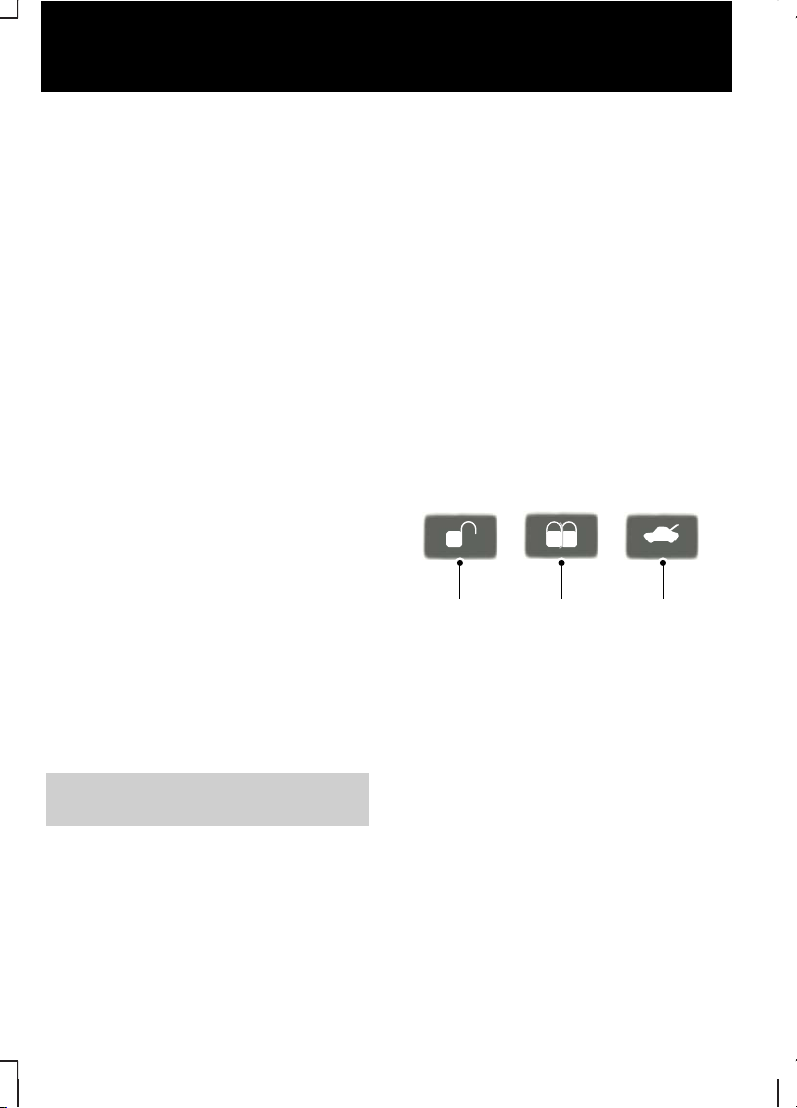
Symbols on your vehicle
When you see these symbols, read and
follow the relevant instructions in this
handbook before touching or attempting
adjustment of any kind.
PARTS AND ACCESSORIES
Genuine Ford parts and accessories have
been designed specifically for your
vehicle. Unless we have specifically
stated, we have not tested non-Ford
parts and accessories and, therefore, we
will not guarantee that they are suitable
for your vehicle. We recommend that you
ask your Ford Dealer for advice on parts
and accessories suitable for your vehicle.
5
Introduction
Page 8
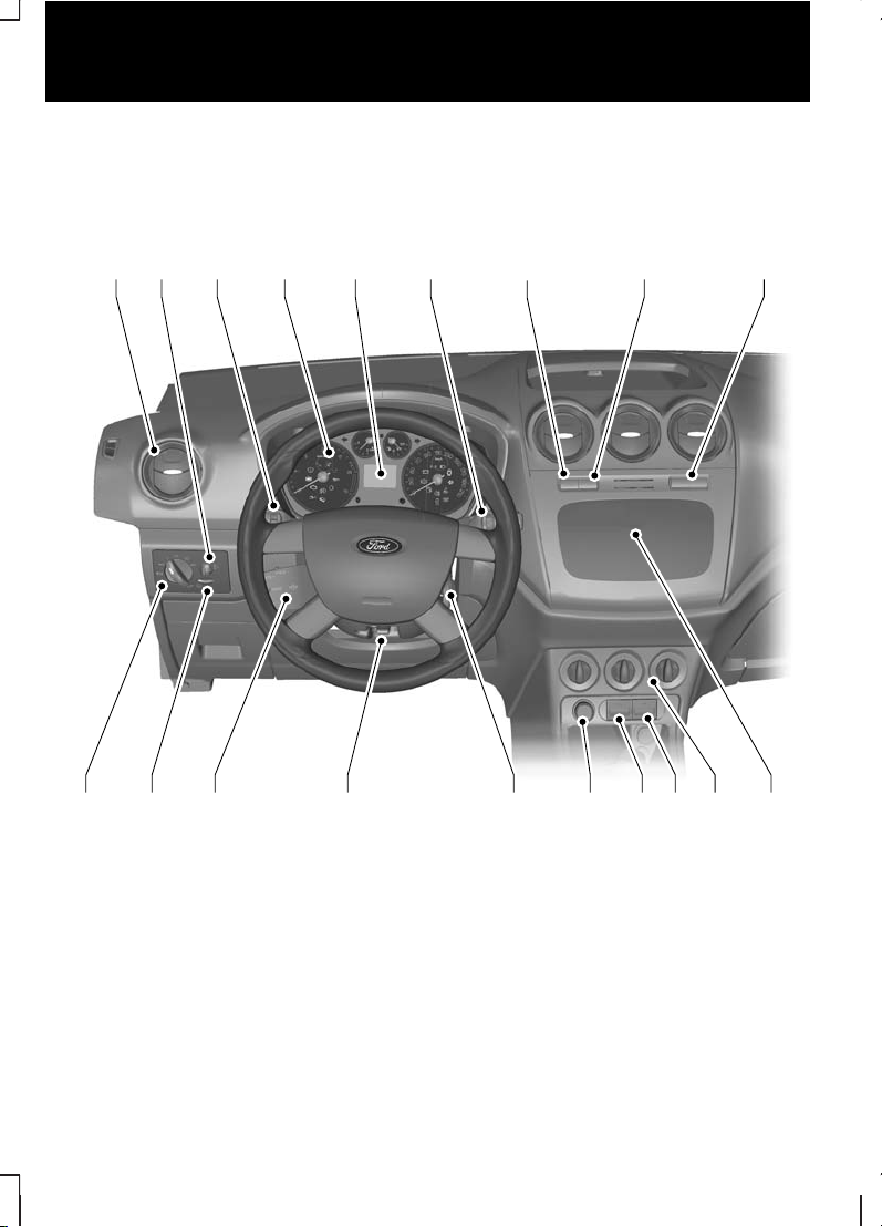
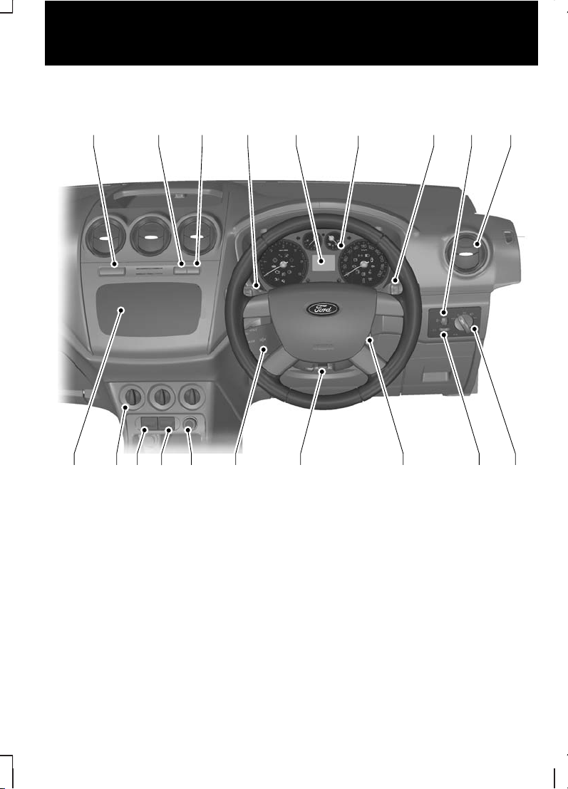
QUICK START
Instrument panel overview
Left-hand drive
E115781
IH
G
FD ECA B
S Q PR O N M KL J
6
Quick start
Page 9
Right-hand drive
ABF
D
EH CGI
J PQK OL
M
N R S
E115782
Air vent. See Climate control (page 63).
A
Headlamp levelling control. See Headlamp levelling (page 39).
B
Direction indicators. See Lighting (page 37).
C
Instrument cluster. See Gauges (page 50).
D
Information display. See (page 56).
E
Wiper lever. See Wipers and washers (page 33).
F
Hazard warning flasher switch. See Lighting (page 37).
G
Passenger airbag disabled indicatator. See Disabling the passenger
airbag (page 19).
H
7
Quick start
Page 10
Heated windscreen and heated rear window switches. See Climate control
(page 63).
I
Audio or navigation unit. See separate handbook.J
Climate controls. See Climate control (page 63).
K
Recirculated air switch. See Climate control (page 63).
L
Air conditioning switch. See Climate control (page 63).
M
Cigar lighter or auxiliary power socket. See Convenience features (page
78).
N
Ignition switch.O
Steering wheel adjustment lever. See Steering wheel (page 30).
p
Audio control. See Audio control (page 30).
Q
Instrument lighting dimmer. See Instrument lighting dimmer (page 78).
R
Lighting controls. See Lighting (page 37).
S
Locking and unlocking the
doors with the key
Allvehicles
Turn the top of the key towards the front
of the vehicle twice to unlock all doors.
Transit Connect
Turn the top of the key towards the front
of the vehicle to unlock the front doors.
Tourneo Connect
Turn the top of the key towards the front
of the vehicle to unlock the front and
sliding doors.
See Locking and unlocking (page
23).
Locking and unlocking the
doors with the remote control
E87379
A B C
UnlockA
LockB
Luggage compartment lid
unlock
C
Transit Connect
Press button A once to unlock the front
doors only.
Press button A twice to unlock all doors.
Press button C once to unlock the sliding
door and the luggage compartment lid.
8
Quick start
Page 11
Tourneo Connect
Press button A once to unlock the front
and sliding doors.
Press button A twice to unlock all doors.
Press button C once to unlock the
luggage compartment lid.
All vehicles
Press button B once to lock all doors and
the luggage compartment lid.
Press button B twice within three
seconds to activate double locking.
Note:
The anti-theft alarm system can
also be armed independently from the
double locking system by turning the door
key to the lock position.
See Locking and unlocking (page
23).
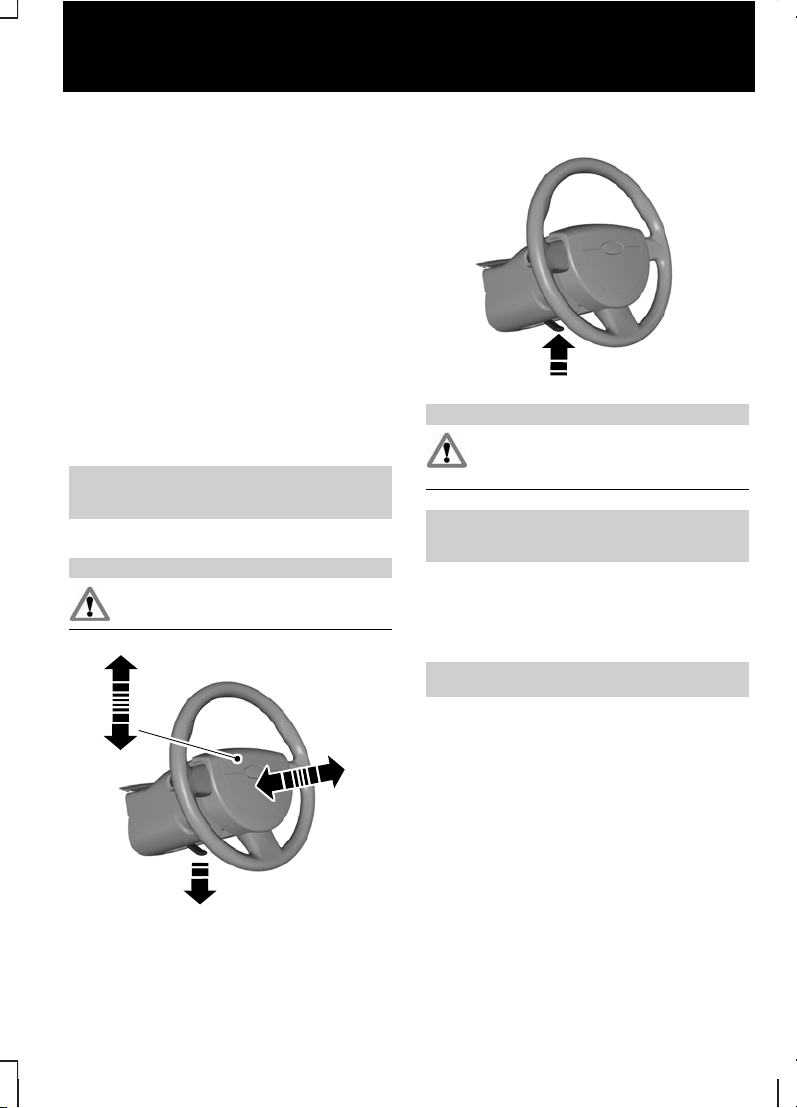
Adjusting the steering wheel
WARNING
Never adjust the steering wheel
when the vehicle is moving.
1
2
2
E95178
3
E95179
WARNING
Make sure that you fully engage the
locking lever when returning it to its
original position.
See Adjusting the steering wheel
(page 30).
Engine idle speed after starting
The engine may idle at a higher speed
than normal immediately after starting
from cold.
See Starting the engine (page 81).
9
Quick start
Page 12
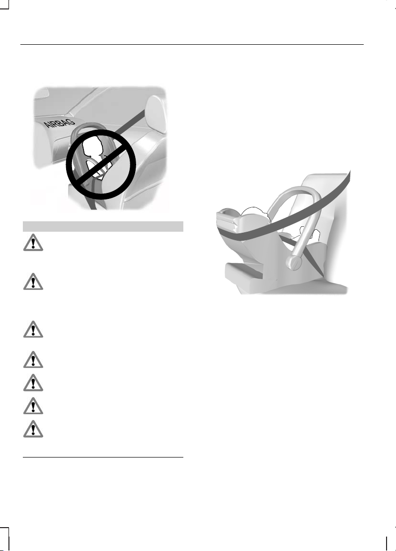
CHILD SEATS
E68916
WARNINGS
Secure children that are less than
150 centimetres tall or less than 12
years of age in a suitable, approved
child restraint, in the rear seat.
Original text according to ECE
R94.01: Extreme Hazard! Do not use
a rearward facing child restraint on
a seat protected by an air bag in front of
it!
Read and follow the manufacturer’s
instructions when you are fitting a
child restraint.
Do not modify child restraints in any
way.
Do not hold a child on your lap when
the vehicle is moving.
Do not leave unattended children in
your vehicle.
If your vehicle has been involved in
an accident, have the child restraints
checked by properly trained
technicians.
Note:
Mandatory use of child restraints
varies from country to country.
Only child restraints certified to
ECE-R44.03 (or later) have been tested
and approved for use in your vehicle. A
choice of these are available from your
Dealer.
Child restraints for different
mass groups
Use the correct child restraint as follows:
Baby safety seat
E68918
Secure children that weigh less than 13
kilograms in a rearward facing baby safety
seat (Group 0+) in the rear seat.
10
Child safety
Page 13
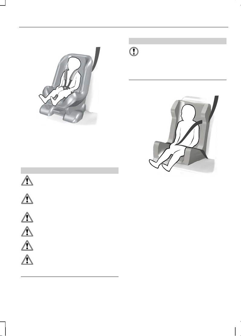
Child safety seat
E68920
Secure children that weigh between 13
and 18 kilograms in a child safety seat
(Group 1) in the rear seat.
BOOSTER CUSHIONS
WARNINGS
Do not install a booster seat or a
booster cushion with only the lap
strap of the seat belt.
Do not install a booster seat or a
booster cushion with a seat belt that
is slack or twisted.
Do not put the seat belt under your
child’s arm or behind its back.
Do not use pillows, books or towels
to boost your child’s height.
Make sure that your children sit in
an upright position.
Secure children that weigh more
than 15 kilograms but are less than
150 centimetres tall in a booster
seat or a booster cushion.
CAUTION
When using a child seat on a rear
seat, make sure that the child seat
rests tightly against the vehicle seat.
It may be necessary to lift or remove the
head restraint. See Head restraints
(page 74).
Booster seat (Group 2)
E70710
We recommend that you use a booster
seat that combines a cushion with a
backrest instead of a booster cushion
only. The raised seating position will allow
you to position the shoulder strap of the
adult seat belt over the centre of your
child’s shoulder and the lap strap tightly
across its hips.
11
Child safety
Page 14
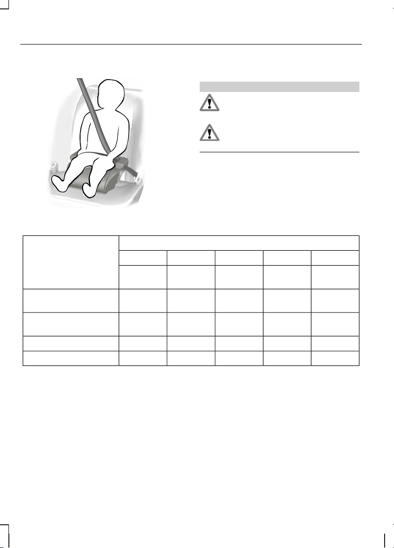
Booster cushion (Group 3)
E68924
CHILD SEAT POSITIONING
WARNINGS
When using a forward facing child
seat on a rear seat, always remove
the head restraint from that seat.
When fitting a child seat using the
vehicle seat belts make sure the
belts are not slack.
Note:
When using a child restraint on a
front seat, it may prove difficult to tighten
the lap section of the seat belt without
slack remaining. If this is the case, adjust
the seatback to the fully upright position
and raise the height of the seat. See
Front seats (page 71).
Mass group categories
Seating positions
IIIIII0+0
22 to 36
kg
15 to 25
kg
9 to 18 kgUp to 13
kg
Up to 10
kg
U
1
U
1
U
1
XX
Front passenger seat
with airbag
U
1
U
1
U
1
U
1
U
1
Front passenger seat
without airbag
UUUUUSecond row rear seats
UUUUUThird row rear seats
X Not suitable for children in this mass group.
U Suitable for universal category child restraints approved for use in this mass group.
U1Suitable for universal category child restraints approved for use in this mass group.
However, we recommend that you secure children in a government approved child
restraint, in the rear seat.
12
Child safety
Page 15

ISOFIX child restraints
Mass group categoriesSeating positions
IIIIII0+0
22 - 36 kg15 - 25 kg9 - 18 kgUp to 13
kg
Up to 10
kg
XX
L
**
L
**
XSecond row ISOFIX
seats
XXA, B, B1, C,
D
C, D, EESecond row ISOFIX
classes*
X Not suitable for children in this mass group.
L Recommended only for the following rearward facing ISOFIX child restraints: Roemer
Baby-Safe (E1-04301146), Roemer Baby-Safe Plus (E1-04301146), Britax Cosy Tot
(E1-04301146), Britax Cosy Tot Premium (E1-04301146).
L Recommended only for the following forward facing ISOFIX child restraint with top
tether (group I): Roemer Duo (E1-40301133).
*
As defined by ECE-R16.
N/A Not applicable.
Note:
**
When you are purchasing an ISOFIX restraint, make sure that you know the
correct mass group and ISOFIX size class for the intended seating locations.
13
Child safety
Page 16
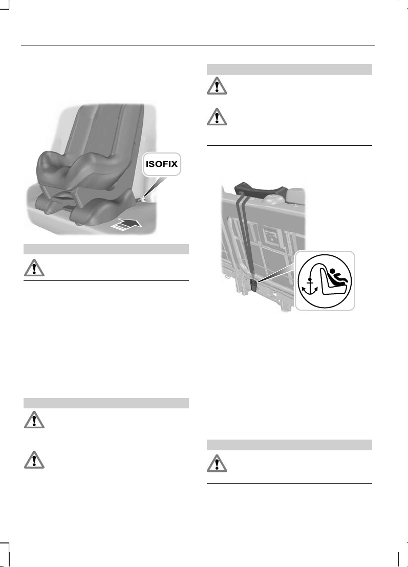
ISOFIX ANCHOR POINTS
Tourneo Connect
E68945
WARNING
Use only ISOFIX child seats we
recommend.
You can fit ISOFIX child restraints using
the ISOFIX anchor points.
The ISOFIX system comprises of two rigid
attachment arms on the child restraint
that attach to anchor points on the rear
seats, where the cushion and backrest
meet. Tether anchor points may also be
fitted.
Attaching a child restraint with a top
tether
WARNINGS
Use an anti-rotation device when
using the ISOFIX system. We
recommend that you use a top
tether or a support leg.
For ISOFIX child seats fitted with a
top tether, always use a top tether
anchor point.
WARNINGS
Do not attach a tether strap to
anything other than the correct
tether anchor point.
Always use the top tether anchor
point at the base of the second row
seatback when the third row is
occupied.
1. Remove the head restraint. See
Head restraints (page 74).
E75771
2. Route the tether strap to the anchor
point.
3. Push the child seat back firmly to
engage the ISOFIX lower anchor
points.
4. Tighten the tether strap in line with the
child seat manufacturer's instructions.
CHILD SAFETY LOCKS
Tourneo Connect
WARNING
You cannot open the doors from
inside if you have put the child safety
locks on.
14
Child safety
Page 17
Note:
Child safety locks are only fitted to
sliding doors.
A
B
E75766
LockA
UnlockB
15
Child safety
Page 18
PRINCIPLE OF OPERATION
Airbags
WARNINGS
Do not modify the front of your
vehicle in any way. This could
adversely affect deployment of the
airbags.
Original text according to ECE
R94.01: Extreme Hazard! Do not use
a rearward facing child restraint on
a seat protected by an airbag in front of
it!
Wear a seat belt and keep sufficient
distance between yourself and the
steering wheel. Only when you use
the seat belt properly, can it hold you in a
position that allows the airbag to achieve
its optimum effect. See Sitting in the
correct position (page 71).
Have repairs to the steering wheel,
steering column, seats, airbags and
seat belts carried out by properly
trained technicians.
Keep the areas in front of the
airbags free from obstruction. Do
not affix anything to or over the
airbag covers.
Do not poke sharp objects into
areas where airbags are fitted. This
could damage and adversely affect
deployment of the airbags.
Use seat covers designed for seats
with side airbags. Have these fitted
by properly trained technicians.
Note:
You will hear a loud bang and see
a cloudof harmless powdery residue if an
airbag deploys. This is normal.
Note:
Only wipe airbag covers with a
damp cloth.
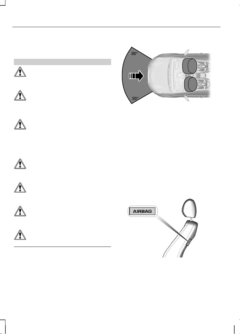
Driver and front passenger airbags
E74302
The driver and front passenger airbags
will deploy during significant frontal
collisions or collisions that are up to 30
degrees from the left or the right. The
airbags will inflate within a few
thousandths of a second and deflate on
contact with the occupants, thus
cushioning forward body movement.
During minor frontal collisions, overturns,
rear collisions and side collisions, the driver
and front passenger airbags will not
deploy.
Side airbags
E72658
Side airbags are fitted inside the seatback
of the front seats. A label indicates that
side airbags are fitted to your vehicle.
16
Occupant protection
Page 19
The side airbags will deploy during
significant lateral collisions. Only the airbag
on the side affected by the collision will
deploy. The airbags will inflate within a few
thousandths of a second and deflate on
contact with the occupants, thus
providing protection for the chest and
shoulder areas. During minor lateral
collisions, overturns, front collisions and
rear collisions, the side airbags will not
deploy.
Seat belts
WARNINGS
Wear a seat belt and keep sufficient
distance between yourself and the
steering wheel. Only when you use
the seat belt properly, can it hold you in a
position to achieve its optimum effect.
See Sitting in the correct position
(page 71).
Never use a seat belt for more than
one person.
Use the correct buckle for each seat
belt.
Do not use a seat belt that is slack
or twisted.
Do notwear thick clothing. The seat
belt must fit tightly around your body
to achieve its optimum effect.
Position the shoulder strap of the
seat belt over the centre of your
shoulder and position the lap strap
tightly across your hips.
The drivers seat belt retractor is fitted with
a seat belt pretensioner. Seat belt
pretensioners have a slightly lower
deployment threshold than the airbags.
During significant frontal collisions, it is
possible that only the seat belt
pretensioners will deploy.
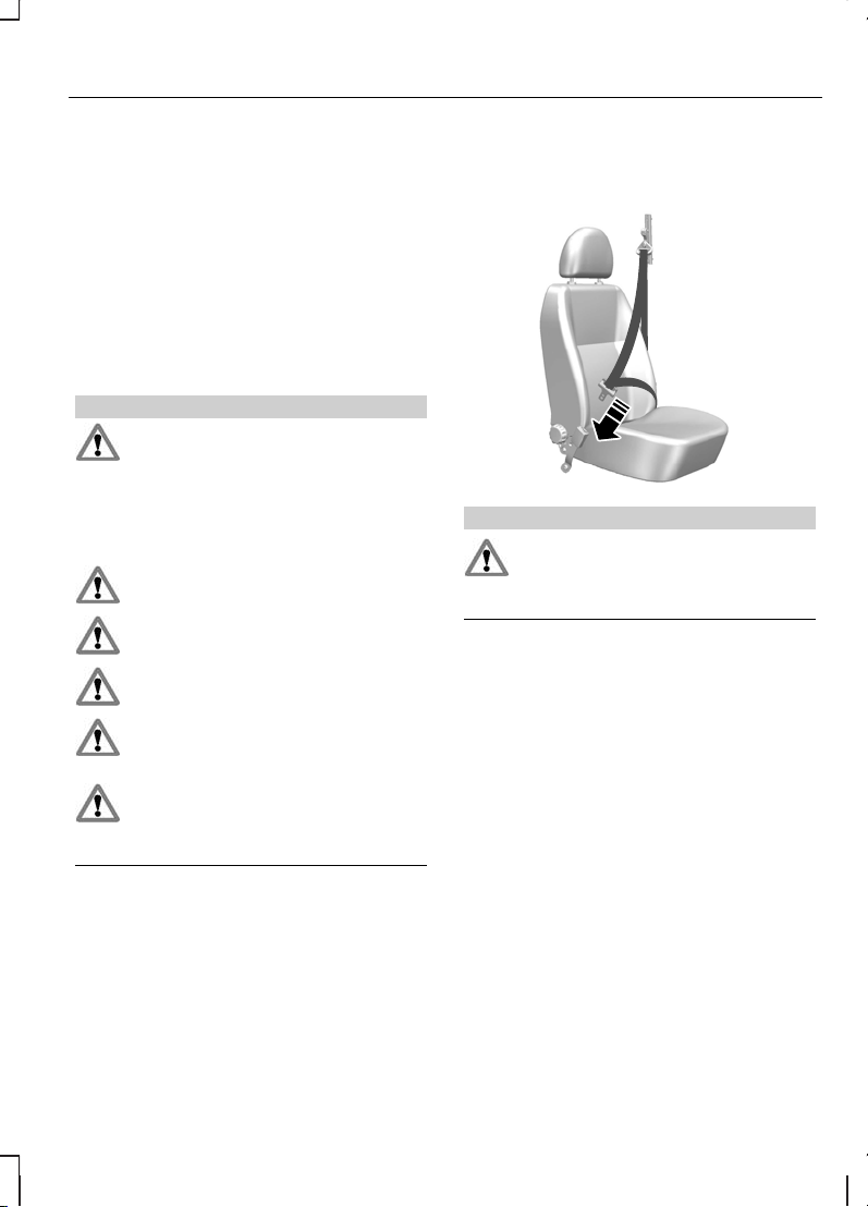
FASTENING THE SEAT BELTS
E66541
WARNING
Insert the tongue into the buckle
until a distinct click is heard,
otherwise the seat belt will not be
locked correctly.
Pull the belt out steadily. It may lock if
pulled sharply or if the vehicle is on a
slope.
To release the belt, press the red button
on the buckle and let the belt rewind
completely and smoothly.
17
Occupant protection
Page 20
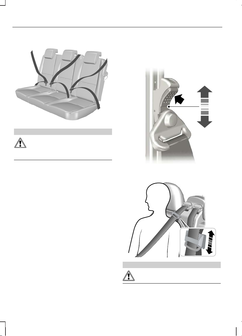
Rear seat belts
E75564
WARNING
In order to ensure that the centre
belt works properly, the rear
seatback must be correctly
engaged.
Make sure that each seat belt uses the
correct buckle.
SEAT BELT HEIGHT ADJUSTMENT
Front seat belt
E68901
Rear seat belt
E73074
WARNING
Make sure that the seat belt runs
smoothly through the guide.
18
Occupant protection
Page 21
SEAT BELT REMINDER
WARNING
The occupant protection system will
only provide optimum protection
when you use the seat belt properly.
The seat belt reminder warning
lamp illuminates and an audible
warning will sound if the driver's
seat belt has not been fastened and the
vehicle exceeds a relatively low speed. It
will also illuminate if the driver's seat belt
is unfastened when the vehicle is moving.
The audible warning will go off after five
minutes but the seat belt reminder
warning lamp will remain on until the
driver's seat belt is fastened.
Deactivating the seat belt
reminder
See your dealer.
USING SEAT BELTS DURING PREGNANCY
E68587
WARNING
Position the seat belt correctly for
your safety and that of your unborn
child. Do not use only the lap strap
or the shoulder strap.
Position the lap strap comfortably across
your hips and low beneath your pregnant
abdomen. Position the shoulder strap
between your breasts, above and to the
side of your pregnant abdomen.
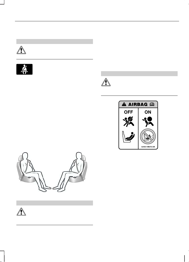
DISABLING THE PASSENGER AIRBAG
WARNING
To avoid the risk of death or serious
injury, NEVER use a rearward
facing child restraint in the front,
unless the airbag is OFF.
E71313
The key switch and the airbag
deactivation lamp are located in the
instrument panel.
If the airbag warning lamp in the
instrument cluster illuminates
intermittently, it means that there is a
malfunction. Remove the child restraint
from the front. Have the system checked
by a suitably trained technician for your
own safety. See Warning lamps and
indicators (page 52).
19
Occupant protection
Page 22
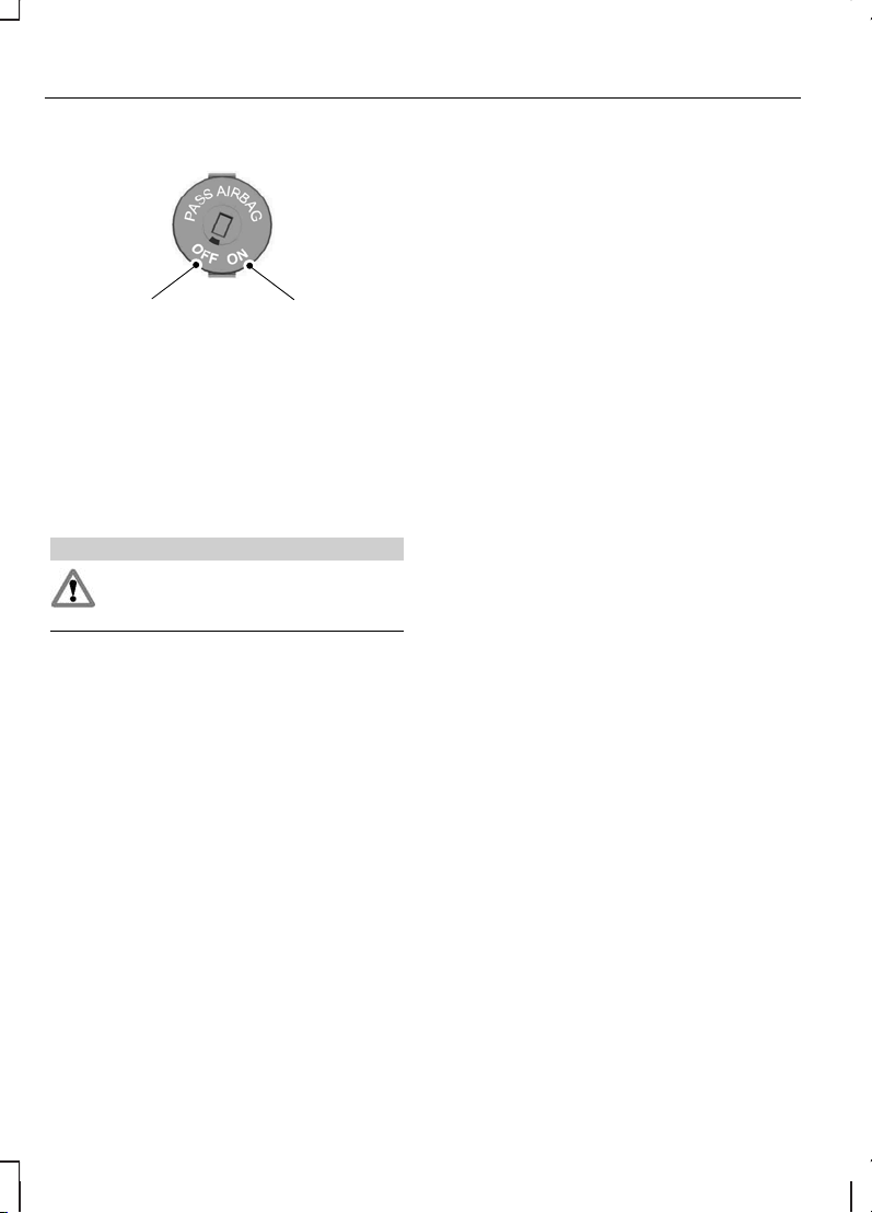
Disabling the passenger airbag
A B
E71312
To use a child restraint in the front, make
sure that the key switch is turned to
position A.
When you switch the ignition on, check
that the passenger airbag deactivation
warning lamp comes on. See Quick
start (page 6).
Enabling the passenger airbag
WARNING
For the adult restraint system to
perform as intended, make sure that
the airbag is ON.
After removing the child restraint from the
front, make sure that you turn the key
switch to position B.
20
Occupant protection
Page 23
GENERALINFORMATIONON RADIO FREQUENCIES
CAUTION
The radio frequency used by your
remote control can also be used by
other short distance radio
transmissions (e.g. amateur radios,
medical equipment, wireless headphones,
remote controls and alarm systems). If
the frequencies are jammed, you will not
be able to use your remote control. You
can lock and unlock the doors with the
key.
Note:
You could unlock the doors if you
press the buttons on the remote control
unintentionally.
The operating range between your
remote control and your vehicle varies
depending on the environment.
PROGRAMMING THE REMOTE CONTROL
A maximum of four remote controls
(including any supplied with your vehicle)
can be programmed. The remote controls
must remain inside the vehicle during the
programming procedure. Fasten the front
seat belts and close all doors to ensure
that conflicting chimes do not sound
during programming.
Programming a new remote
control
1. To programme new remote controls
turn the ignition key to position II four
times within six seconds.
2.
Turn the ignition to position 0. A tone
sounds to indicate that it is now
possible to programme the remote
controls for ten seconds.
3. Press any button on a new remote
control. A tone will sound as
confirmation.
4. Repeat this last step for all your
remote controls, including your
original. Do not remove the key from
the ignition when pressing the button
on this remote control.
5. Switch the ignition back on (position
II) or wait for ten seconds without
programming another remote control
to end the key programming. Only the
remote controls which you have just
programmed are now able to lock and
unlock the vehicle.
Reprogramming the unlocking
function
Note:
When you press the unlock button
either all the doors are unlocked or
depending on the locking configuration,
specific doors are unlocked. Pressing the
unlock button again unlocks all the doors.
Press and hold the unlock and lock
buttons on the remote key simultaneously
for at least four seconds with the ignition
off. The direction indicators will flash twice
to confirm the change.
To return to the original unlocking function,
repeat the process.
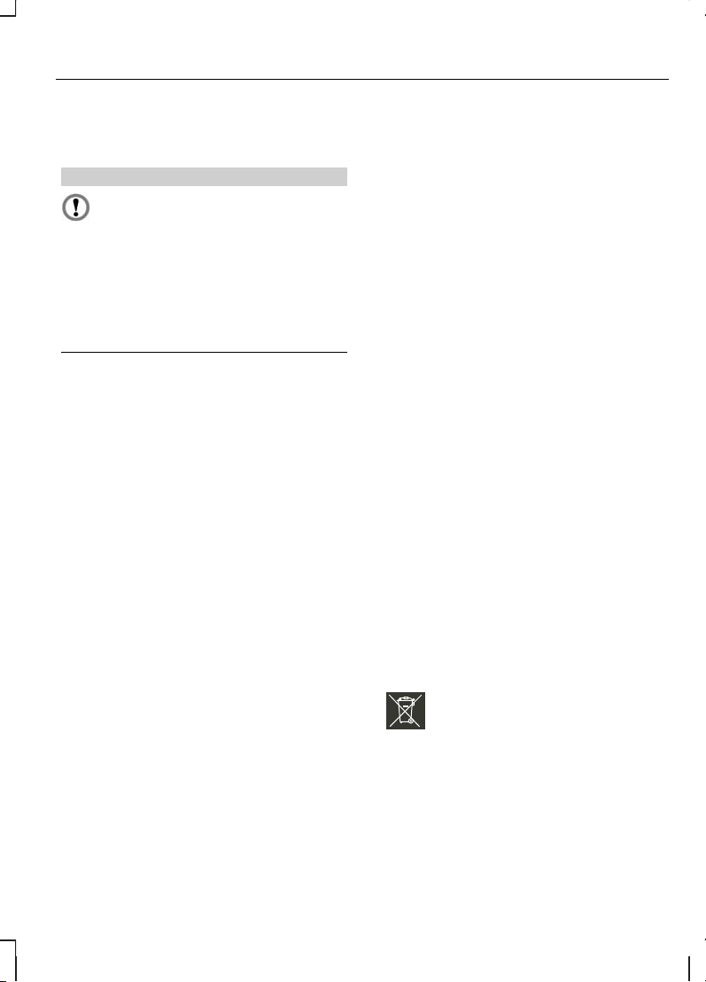
CHANGING THE REMOTE CONTROL BATTERY
E107998
Make sure that you dispose of
old batteries in an
environmentally friendly way.
Seek advice from your local authority
regarding recycling.
21
Keys and remote controls
Page 24

E74386
1. Insert a screwdriver into the recess on
the back of the key and remove the
key blade.
2. Release the retaining clips with the
screwdriver and separate the two
halves of the remote control.
CAUTION
Do not touch the battery contacts or
the printed circuit board with the
screwdriver.
3. Carefully prise out the battery with the
screwdriver.
4. Install a new battery (3V CR 2032) with
the + facing upwards.
5. Assemble the two halves of the
remote control.
6. Install the key blade.
22
Keys and remote controls
Page 25
LOCKING AND UNLOCKING
Central locking
Note:
You can unlock all the doors and
luggage compartment lid with the key
from the front doors. This needs to be
used if the remote control system is not
functioning. If single stage unlocking is
disabled turn the key twice to the unlock
position.
Note:
Unlocking the luggage
compartment lid with a key will only unlock
that door.
Note:
You can only centrally lock the
doors if they are all closed.
Double locking
WARNING
Do not activate double locking when
persons or animals are inside the
vehicle. You will not be able to
unlock the doors from the inside if you
have double locked them.
Double locking is a theft protection feature
that prevents someone from opening the
doors from the inside. You can only
double lock the doors if they are all closed.
Locking and unlocking
confirmation
When you unlock the doors, the direction
indicators will flash once.
On vehicles without double locking, the
direction indicators will flash twice when
you lock the doors.
On vehicles with double locking, the
direction indicators will flash twice when
you double lock the doors.
Unlocking the doors with the
key
Note:
If single stage unlocking is enabled
all doors will be unlocked with one turn of
the key or one press of button A on the
remote.
All vehicles
Turn the top of the key towards the front
of the vehicle twice to unlock all doors.
Transit Connect
Turn the top of the key towards the front
of the vehicle to unlock the front doors.
Tourneo Connect
Turn the top of the key towards the front
of the vehicle to unlock the front doors
and sliding doors.
Locking the doors with the key
Turn the top of the key towards the rear
of the vehicle to lock all doors.
Locking and unlocking the
luggage compartment lid
You can lock or double lock the whole
vehicle or unlock the luggage
compartment lid with the key at the
luggage compartment lid.
Double locking the doors with
the key
Turn the key to the unlock position and
then the lock position within three
seconds to double lock the doors.
23
Locks
Page 26

Locking and unlocking the
doors with the remote control
E87379
A B C
UnlockA
LockB
Luggage compartment lid
unlock
C
Note:
The alarm system is armed when
the vehicle is locked with either the key
or by pressing button B on the remote
control.
Note:
Depending on the vehicle
configuration, the doors unlocked with
one turn of the key or press of button A
on the remote control may vary.
Note:
Button C will remain functional
when the ignition is on if the vehicle is
stationary or moving very slowly.
Transit Connect
Press button A once to unlock the front
doors only.
Press button A twice to unlock all doors.
Press button C once to unlock the sliding
door and luggage compartment lid.
Tourneo Connect
Press button A once to unlock the front
doors and sliding doors.
Press button A twice to unlock all doors.
Press button C once to unlock the
luggage compartment lid.
All vehicles
Press button B once to lock all doors.
Press button B twice within three
seconds to activate double locking.
One-stage unlocking
You can programme the locking system
so that all doors are unlocked with one
key turn in a front door or a press of
button A on the remote control.
Type 1 See Personalised settings
(page 59).
Type2 See Programmingthe remote
control (page 21).
Two-stage unlocking
Two stage unlocking is the default unlock
setting if one stage unlocking is not
enabled.
One key turn or a press of button A on
the remote control will unlock the first
stage. Two key turns or two presses of
button A on the remote control will unlock
all the doors.
One press of button C on the remote
control will unlock the luggage
compartment lid. Two presses of button
C on the remote control will unlock all the
doors.
Automatic relocking
The doors will relock automatically if you
do not open a door within 45 seconds of
unlocking the doors with the remote
control. The door locks and the alarm will
return to their previous state.
Sliding door memory locking
If the vehicle is locked when a sliding door
is open, the sliding door will become
locked when it is closed. It is not possible
to double lock the vehicle with a sliding
door open.
24
Locks
Page 27
Locking and unlocking the
doors from inside
Front doors
E74704
A
B
Lock all doorsA
UnlockB
Note:
Dependent on vehicle lock
configuration different doors will open
using B. If single stage unlocking is
enabled all doors will be unlocked.
Sliding door
E74706
A B
LockA
UnlockB
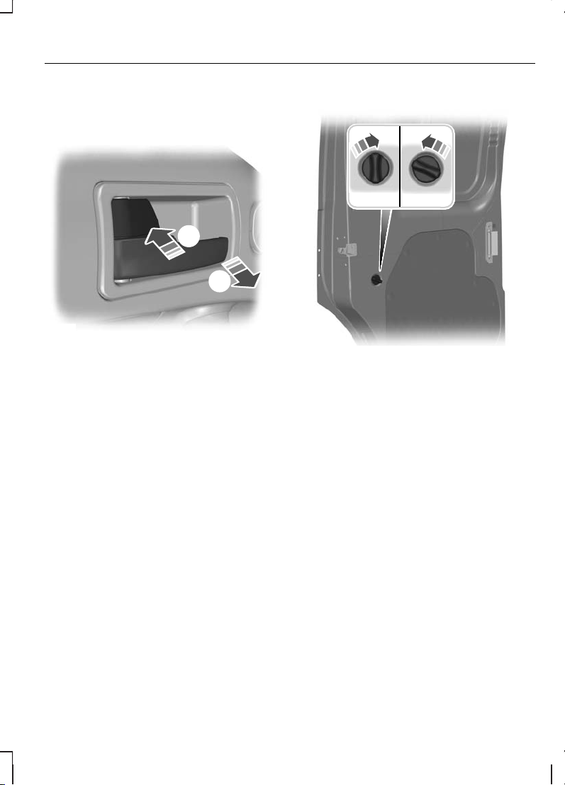
Opening the doors
Sliding door
Note:
On Tourneo Connect, the
right-hand sliding door is inhibited from
opening fully when the fuel filler flap is
unlocked and open.
25
Locks
Page 28
1
2
A
B
E74705
OutsideA
InsideB
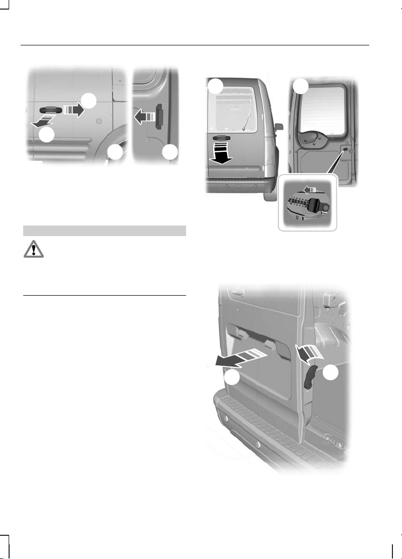
Double rear doors
WARNING
Close the rear doors properly to
prevent them from opening while
you are driving. Driving with the rear
doors open is extremely dangerous as
exhaust fumes can be drawn into the
vehicle’s interior.
Right-hand rear door
E74707
BA
OutsideA
InsideB
Left-hand rear door
E74708
1
2
26
Locks
Page 29
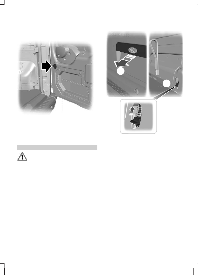
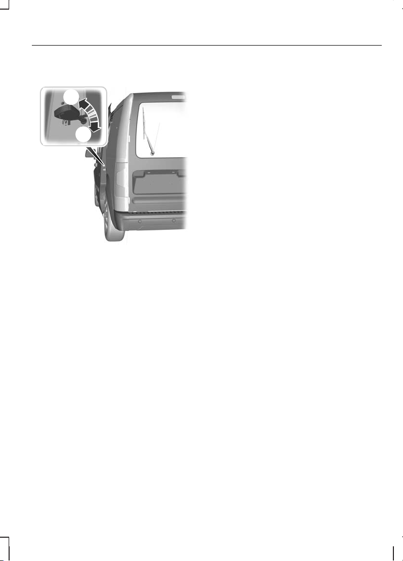
Opening the doors through 180 and
250 degrees
E74709
Push the yellow button located on the
door. The check arms will automatically
re-engage when the doors are closed.
Luggage compartment lid
WARNING
Close the luggage compartment lid
properly to prevent it opening while
you are driving. Driving with it open
is extremely dangerous as exhaust fumes
can be drawn into the vehicle’s interior.
Note:
To open theluggage compartment
lid from inside, you can access the release
button through an aperture at the bottom
of the luggage compartment lid.
A
B
E66517
OutsideA
InsideB
27
Locks
Page 30

PRINCIPLE OF OPERATION
The engine immobiliser is a theft
protection system that prevents someone
from starting the engine with an
incorrectly coded key.
CODED KEYS
Note:
Do not shield your keys with metal
objects. This may prevent the receiver
from recognising your key as a valid one.
Note:
Have all of your remaining keys
erased and recoded if you lose a key. Ask
your dealer for further information. Have
replacement keys recoded together with
your existing keys.
If you lose a key, you can obtain a
replacement from your Ford Dealer. If
possible, provide them with the key
number from the tag provided with the
original keys. You can also obtain
additional keys from your Ford Dealer.
ARMING THE ENGINE IMMOBILISER
The engine immobiliser is armed
automatically a short time after you have
switched the ignition off.
The indicator in the instrument cluster will
flash to confirm that the system is
operating.
DISARMING THE ENGINE IMMOBILISER
The engine immobiliser is disarmed
automatically when you switch the ignition
on with a correctly coded key.
The indicator in the instrument cluster will
come on for approximately three seconds
and then go out. If the indicator stays on
for one minute or flashes for
approximately one minute and then
repeatedly at irregular intervals, your key
has not been recognised. Remove the
key and try again.
If you are unable to start the engine with
a correctly coded key, this indicates a
malfunction. Have the immobiliser
checked immediately.
28
Engine immobiliser
Page 31

PRINCIPLE OF OPERATION
The perimeter alarm is a deterrent against
unauthorised access to your vehicle
through the doors and the bonnet. It also
protects the audio unit.
Triggering the alarm
Once armed, the alarm is triggered in any
of the following ways:
•
If someone opens a door, the luggage
compartment or the bonnet without
a valid key or remote control.
•
If the bonnet is opened with a valid
key.
•
If someone removes the audio or
navigation system.
If the alarm is triggered, the alarm horn will
sound for 30 seconds and the hazard
warning flasher will flash for five minutes.
Any further attempts to perform one of
the above will trigger the alarm again.
ARMING THE ALARM
To arm the alarm, lock the vehicle. See
Locks (page 23).
DISARMING THE ALARM
Disarm and silence the alarm by unlocking
either of the front doors or luggage
compartment with the key.
29
Alarm
Page 32

ADJUSTING THE STEERING WHEEL
WARNING
Never adjust the steering wheel
when the vehicle is moving.
Note:
Make sure that you are sitting in
the correct position. See Sitting in the
correct position (page 71).
1
2
2
E95178
3
E95179
WARNING
Make sure that you fully engage the
locking lever when returning it to its
original position.
AUDIO CONTROL
Select radio or CD mode on the audio
unit.
The following functions can be operated
with the remote control:
Volume
E116379
Volume up: Press the top button on the
back of the remote control.
Volume down: Press the bottom button
on the back of the remote control.
30
Steering wheel
Page 33

Seek
E116380
Move the lever up or down:
•
In radio mode, this will locate the
next radio station up or down the
frequency band.
•
In CD mode, it will select the next or
previous track.
Mode
E116297
Briefly press the button on the side:
•
In radio mode, this will locate the
next pre-set radio station.
•
In CD mode, this will select the next
CD if a CD changer is fitted.
•
In all modes to abort a traffic
message during broadcasting.
Press and hold the button on the side:
•
In radio mode to change the
waveband.
VOICE CONTROL
For further information See Voice
control (page 139).
To select or deselect voice control:
31
Steering wheel
Page 34

E116297
32
Steering wheel
Page 35

WINDSCREEN WIPERS
E71012
A
B
C
D
Single wipeA
Intermittent wipe or autowipersB
Normal wipeC
High speed wipeD
Intermittent wipe
E71013
C
A
B
Long wipe intervalA
Intermittent wipeB
Short wipe intervalC
AUTOWIPERS
CAUTIONS
Do not switch autowipers on in dry
weather conditions. The rain sensor
is very sensitive and the wipers may
operate if dirt, mist or flies hit the
windscreen.
Replace the wiper blades as soon as
they begin to leave bands of water
and smears. If you do not replace
them, the rain sensor will continue to
detect water on the windscreen and the
wipers will operate, even though the
majority of the windscreen is dry.
Fully defrost the windscreen in icy
conditions before you switch
autowipers on.
Switch autowipers off before you
enter a car wash.
E71013
C
A
B
Low sensitivityA
OnB
High sensitivityC
If you switch autowipers on, the wipers
will not cycle until water is detected on
the windscreen. The rain sensor will then
continuously measure the amount of
water on the windscreen and adjust the
speed of the wipers automatically.
33
Wipers and washers
Page 36

Adjust the sensitivity of the rain sensor
using the rotary control. With low
sensitivity, the wipers will operate when
the sensor detects a lot of water on the
windscreen. With high sensitivity, the
wipers will operate if the sensor detects
a small amount of water on the
windscreen.
WINDSCREEN WASHERS
E71016
WARNING
Do not operate the washer for more
than 10 seconds at a time, and
never when the reservoir is empty.
While the button at the end of the lever is
pressed the washer will work in
conjunction with the wipers.
After releasing the button, the wipers
operate for a short time.
REAR WINDOW WIPER AND WASHERS
Intermittent wipe
E71017
Pull the lever towards the steering wheel.
Reverse gear wipe
The rear wiper will be activated
automatically when selecting reverse gear
if:
•
the rear wiper is not already switched
on,
•
the wiper lever is in position A, B, C
or D and
•
the front wiper is operating (when set
to position B).
The rear wiper will follow the front wiper
interval (at intermittent or normal speed).
34
Wipers and washers
Page 37

Rear window washer
E71018
WARNING
Do not operate the washer for more
than 10 seconds at a time, and
never when the reservoir is empty.
While the lever is pulled towards the
steering wheel the washer will work in
conjunction with the wipers.
Once the wash and wipe cycle is
completed, the wipers will pause and then
perform one more wipe to clear the
windscreen.
After releasing the lever, the wipers
operate for a short time.
CHECKING THE WIPER BLADES
E66644
Run the tip of your fingers over the edge
of the blade to check for roughness.
Clean the wiper blade lips with water
applied with a soft sponge.
CHANGING THE WIPER BLADES
E93783
1
2
35
Wipers and washers
Page 38

E93784
3
5
4
E93785
6
E93786
Install in the reverse order.
36
Wipers and washers
Page 39

LIGHTING CONTROL
Lighting control positions
E71094
D
B CAF
E
OffA
Side and tail lampsB
HeadlampsC
Front fog lampsD
Rear fog lampsE
Parking lampsF
Parking lamps
First, switch off the ignition.
Push the lighting control inwards and turn
it to position F.
Main and dipped beam
E71095
Pull the lever fully towards the steering
wheel to switch between main and
dipped beam.
Headlamp flasher
Pull the lever slightly towards the steering
wheel.
Home safe lighting
You can switch home safe lighting on up
to 10 minutes after you have switched the
ignition off.
Vehicles without autolamps
Switch the headlamps on and then switch
them off within two seconds.
Vehicles with autolamps
1.
Switch autolamps on and then switch
them off within two seconds.
2.
Switch autolamps off and then switch
them on within two seconds
All vehicles
The headlamps will go off automatically
after 3 minutes with any door open, or 30
seconds after the last door has been
closed.
37
Lighting
Page 40

With all doors closed, but within the 30
second delay, opening any door will result
in the 3 minute timer starting again.
The home safe lights can be cancelled by
either turning the headlamp switch ON or
by turning the ignition switch ON.
AUTOLAMPS
E73840
Note:
If you have switched autolamps
on, you can only switch the main beam
on when autolamps has switched the
headlamps on.
The headlamps will come on and go off
automatically depending on the ambient
light.
FRONT FOG LAMPS
E71096
WARNING
Only use the front fog lamps when
visibility is considerably restricted by
fog, snow or rain.
Note:
You cannot switch the front fog
lamps on if you have switched autolamps
on.
REAR FOG LAMPS
E71097
WARNING
Do not use the rear fog lamps when
it is raining or snowing and visibility
is more than 50 metres.
38
Lighting
Page 41

Note:
You cannot switch the rear fog
lamps on if you have switched autolamps
on.
HAZARD WARNING FLASHERS
Note:
Depending on applicable laws and
regulations in the country for which your
vehicle was originally built, the hazard
warning flashers may flash if you brake
heavily.
E71943
For item location: See Quick start (page
6).
HEADLAMP LEVELLING
All vehicles
E65990
You can adjust the level of the headlamp
beams according to the vehicle load.
Recommended headlamp
levelling switch positions
Note:
Higher control positions (+1) may
be necessary when towing a trailer.
Transit Connect
Control positionLoad
T220/T230T210T200Load in luggage compart-
ment
1
Persons
Information
not available
Information
not available
Information
not available
-1
/Information
not available
Information
not available
Information
not available
max.
2
1
1
When the vehicle is fitted with the attitude or ride height pack, headlamp levelling may
need to be adjusted.
2
See Vehicle identification (page 126).
3
Long wheelbase.
4
Short wheelbase.
39
Lighting
Page 42

Tourneo Connect
Control positionLoad
K230K220K200/
K210
Load in luggage
compartment
1
Persons
RearFront
Informa-
tion not
available
Informa-
tion not
available
Informa-
tion not
available
--1-2
Informa-
tion not
available
Informa-
tion not
available
Informa-
tion not
available
-12
Informa-
tion not
available
Informa-
tion not
available
Informa-
tion not
available
-32
Informa-
tion not
available
Informa-
tion not
available
Informa-
tion not
available
max.
1
32
Informa-
tion not
available
Informa-
tion not
available
Informa-
tion not
available
max.
1
-1
1
See Vehicle identification (page 126).
2
Long wheelbase.
3
Short wheelbase.
DIRECTION INDICATORS
E71098
Note:
Tap the lever up or down to make
the direction indicators flash only three
times.
40
Lighting
Page 43

INTERIOR LAMPS
B
A
C
E72170
OffA
Door contactB
OnC
If you set the switch to position B, the
courtesy lamp will come on when you
unlock or open a door or the tailgate. If
you leave a door open with the ignition
switch off, the courtesy lamp will go off
automatically after some time to prevent
the vehicle battery from discharging. To
switch it back on, switch on the ignition
for a short time.
The courtesy lamp will also come on when
you switch off the ignition. It will go off
automatically after a short time or when
you start or restart the engine.
If you set the switch to position C with the
ignition switch off, the courtesy lamp will
come on. It will go off automatically after
a short time to prevent the vehicle battery
from discharging. To switch it back on,
switch on the ignition for a short time.
Reading lamps
E72171
CHANGING A BULB
WARNINGS
Switch the lights and the ignition off.
Let the bulb cool down before
removing it.
CAUTIONS
Do not touch the glass of the bulb.
Only fit bulbs of the correct
specification. See Bulb
specification chart (page 46).
Note:
When replacing a bulb, clean the
headlamp lens with a damp cloth to avoid
any electrostatic charging, which attracts
dust to the plastic lens.
Note:
The following instructions describe
how to remove the bulbs. Fit
replacements in the reverse order unless
otherwise stated.
41
Lighting
Page 44

Headlamp
Direction indicator
1
E76059
2
1. Turn the bulb holder anti-clockwise
and remove it.
2. Gently press the bulb into the bulb
holder, turn it anti-clockwise and
remove it.
Headlamp main and dipped beam
1
E76060
Note:
When installing the cover, make
sure the arrow faces up.
1. Turn the cover anti-clockwise and
remove it.
E76062
2
3
2. Disconnect the electrical connector.
3. Release the clip and remove the bulb.
42
Lighting
Page 45

Side lamp
1
E76060
Note:
When installing the cover, make
sure the arrow faces up.
1. Turn the cover anti-clockwise and
remove it.
E76061
3
2
2. Remove the bulb and the bulb holder.
3. Remove the bulb.
Side repeaters
E76063
1
3
2
1. Carefully remove the side repeater.
2. Hold the bulb holder, turn the housing
anti-clockwise and remove it.
3. Remove the bulb.
43
Lighting
Page 46

Front fog lamps
E76064
2
1
Note:
You cannot separate the fog lamp
bulb from the bulb holder.
Note:
You can access the lamp from
behind the front bumper.
1. Disconnect the electrical connector.
2. Turn the bulb holder anti-clockwise
and remove it.
Rear lamps
E76065
1
2 2
E76066
A
B
C
D
Tail and brake lampA
Direction indicatorB
Reversing lampC
Fog lampD
1. Remove the wing nuts.
44
Lighting
Page 47

2. Remove the rear lamp and unclip the
bulb holder.
3. Gently press the bulb into the bulb
holder, turn it anti-clockwise and
remove it.
Central high mounted brake
lamp
E76067
3
2
1
1. Remove the screws.
2. Remove the lamp.
3. Remove the bulb.
Number plate lamp
Vehicles with double rear doors
E71074
2
1
1. Remove the lens.
2. Remove the bulb.
Vehicles with a tailgate
2
2
1
1
E71075
1. Open the lens.
2. Gently press the bulb into the bulb
holder, turn it anti-clockwise and
remove it.
45
Lighting
Page 48

Interior lamp
Front
E76068
2
1
Rear
E76070
1
2
1. Carefully prise out the lamp.
2. Remove the bulb.
Reading lamps
E76069
1
2
2
1. Carefully prise out the lamp.
2. Remove the bulb.
BULB SPECIFICATION CHART
Power (watt)SpecificationLamp
55/60H4Headlamp main and dipped beam
55H11Front fog lamp
21PY21WFront direction indicator
5W5WSide lamp
5WY5WSide repeater
21/5P21/5WBrake and tail lamp
16W16WCentral high mounted brake lamp
21PY21W LLRear direction indicator
46
Lighting
Page 49

Power (watt)SpecificationLamp
21P21WRear fog lamp
10R10WNumber plate lamp (vehicles with a
tailgate)
5W5WNumber plate lamp (vehicles with
double rear doors)
21P21WReversing lamp
10FestoonInterior lamp
6H6WReading lamp
47
Lighting
Page 50

ELECTRIC WINDOWS
WARNING
Do not operate the electric windows
unless they are free from
obstruction.
Note:
If you operate the switches often
during a short period of time, the system
might become inoperable for a certain
time to prevent damage due to
overheating.
E93505
Switch on the ignition to operate the
electric windows.
To open the driver’s window
automatically
Press the switch to the second action
point and release it. Press it again to stop
the window.
EXTERIOR MIRRORS
WARNING
Do not overestimate the distance
of the objects that you see in the
convex mirror. Objects seen in
convex mirrors will appear smaller and
further away than they actually are.
Manual folding mirrors
Folding
Push the mirror towards the door window
glass.
Unfolding
Make sure that you fully engage the mirror
in its support when returning it to its
original position.
ELECTRIC EXTERIOR MIRRORS
E71280
B
C
A
Left-hand mirrorA
OffB
Right-hand mirrorC
E71281
48
Windows and mirrors
Page 51

The electric exterior mirrors are fitted with
a heating element that will defrost or
demist the mirror glass. See Climate
control (page 63).
REAR QUARTER WINDOWS
E66498
Pull the lever outwards to open the
window. Press the lever in the middle to
engage it in its catch. Pull the lever in the
middle to close the window. Push it
backwards until it engages in its catch.
AUTO-DIMMING MIRROR
E71028
The auto-dimming mirror will adjust
automatically when hit by glaring light from
behind. It will not work when you have
selected reverse gear.
49
Windows and mirrors
Page 52

GAUGES
Type 1
A
B
C
D
F EG
E74268
TachometerA
Engine coolant temperature gaugeB
Fuel gaugeC
SpeedometerD
Clock set buttonE
Information displayF
Tripmeter reset buttonG
50
Instruments
Page 53

Type 2
E115885
A
B
C
D
EF
TachometerA
Engine coolant temperature gaugeB
Fuel gaugeC
SpeedometerD
Information displayE
Message indicatorF
Engine coolant temperature
gauge
All vehicles
Shows the temperature of the engine
coolant. At normal operating temperature,
the needle will remain in the centre
section.
CAUTION
Do not restart the engine until the
cause of overheating has been
resolved.
51
Instruments
Page 54

If the needle enters the red section, the
engine is overheating. Stop the engine,
switch the ignition off and determine the
cause once the engine has cooled
down.
Vehicleswithaninformation display
In addition, a warning message will appear
in the display.
Fuel gauge
The arrow adjacent to the fuel pump
symbol tells you on which side of your
vehicle the fuel filler cap is located.
WARNING LAMPS AND INDICATORS
The following warning lamps and
indicators will come on briefly when you
switch the ignition on to confirm that the
system is operational:
•
ABS
•
Airbag
•
Brake system
•
Engine
•
Engine immobiliser
•
Ignition
•
Low fuel level
•
Oil pressure
•
Service interval
•
Shift
•
Stability control (ESP) and traction
control
•
Water-in-fuel
If a warning or indicator lamp does not
illuminate when the ignition is switched
on, this indicates a malfunction. Have the
system checked by a properly trained
technician.
ABS warning lamp
If a warning or indicator lamp
does not illuminate when the
ignition is switched on, this
indicates a malfunction. Have the system
checked by properly trained technician.
Airbag warning lamp
If it illuminates when driving, this
indicates a malfunction. Have
the system checked by a
properly trained technician.
Brake system warning lamp
It illuminates when the parking
brake is engaged.
WARNING
Reduce your speed gradually and
stop your vehicle as soon as it is
safe to do so. Use your brakes with
care.
If it illuminates when you are driving, check
that the parking brake is not engaged. If
the parking brake is not engaged, this
indicates a malfunction. Have the system
checked by a properly trained technician
immediately.
Direction indicator
Flashes during operation. A
sudden increase in the rate of
flashing warns of a failed
indicator bulb. See Changing a bulb
(page 41).
Door open warning lamp
It will illuminate when you switch
the ignition on if you have not
closed the doors, the bonnet or
tailgate properly.
52
Instruments
Page 55

Engine warning lamps
Malfunction indicator lamp
Powertrain warning lamp
All vehicles
If either lamp illuminates when the engine
is running, this indicates a fault. The engine
will continue to run but it may have limited
power. If it flashes when you are driving,
reduce the speed of your vehicle
immediately. If it continues to flash,
avoid heavy acceleration or deceleration.
Have the system checked by a properly
trained technician immediately.
WARNING
Have this checked immediately.
If both lamps illuminate together, stop
your vehicle as soon as it is safe to
do so (continued use may cause
reduced power and cause the engine to
stop). Turn the ignition off and attempt to
restart the engine. If the engine restarts
have the system checked by a properly
trained technician immediately. If the
engine does not restart the vehicle must
be checked before continuing your
journey.
Front fog lamp indicator
It will illuminate when you switch
the front fog lamps on.
Glow plug indicator
See Startinga diesel engine
(page 81).
Headlamp indicator
It will illuminate when you switch
the headlamp dipped beam or
the side and tail lamps on.
Ignition warning lamp
WARNING
If the charging system drive belt on
the diesel engines is loose, torn or
broken, the servo assistance for the
braking system also no longer operates.
If it illuminates whilst driving, this
indicates a malfunction. Switch
off all unnecessary electrical
equipment. Have the system checked by
a properly trained technician immediately.
Low fuel level warning lamp
If it illuminates, refuel as soon as
possible.
The arrow adjacent to the fuel pump
symbol tells you on which side of your
vehicle the fuel filler cap is located.
Main beam indicator
Illuminates when you switch the
headlamp main beam on. It will
flash when you use the
headlamp flasher.
Message indicator
It will illuminate when a new message is
stored in the information display. See
Information messages (page 60).
53
Instruments
Page 56

Oil pressure warning lamp
CAUTION
Do not resume your journey if the oil
pressure warning lamp comes on
despite the oil level being correct.
Have the system checked by a properly
trained technician immediately.
If the lamp stays on after
starting or illuminates during a
journey, this indicates a
malfunction. Stop your vehicle as soon as
it is safe to do so and switch the engine
off. Check the engine oil level. See
Engine oil check (page 111). Top up
straight away if the level is low.
Rear fog lamp indicator
It will illuminate when you switch
the rear fog lamps on.
Service interval indicator
It will illuminate when a service
is due or there is excessive soot
or sludge in the oil. Have the
engine oil changed as soon as possible.
Your dealer will switch the service interval
indicator lamp off for you after completing
the service.
Seat belt reminder
See Seat belt reminder
(page 19).
Shift indicator
It will illuminate for a short period
of time to inform you that
shifting to a higher gear may
give better fuel economy and lower CO2
emissions. It will not illuminate during
periods of high acceleration, braking or
when the clutch pedal is pressed.
Stability control (ESP) and
traction control warning lamp
Note:
If either the ESP system or traction
control system malfunctions, the
respective system will switch off
automatically.
It will flash when either system
is operating. If it does not flash
or it comes on when you are
driving, this indicates a malfunction. Have
the system checked by a properly trained
technician immediately.
If you switch ESP off, the warning lamp
will come on. The lamp will go out when
you switch the system back on or when
you switch the ignition off.
Water-in-fuel indicator
Vehicles with a diesel engine
It will illuminate if there is excess
water in the fuel filter. Have the
system checked by a properly
trained technician immediately.
AUDIBLE WARNINGS AND INDICATORS
Door open
A warning tone will sound if the vehicle
exceeds a relatively low speed and you
have not closed the doors or the bonnet
properly.
54
Instruments
Page 57

Frost
WARNING
Even if the temperature rises to
above +4ºC there is no guarantee
that the road is free of hazards
caused by inclement weather.
A warning chime will sound in the following
conditions:
•
+4ºC or lower: frost warning
•
0ºC or lower: danger of icy roads
Lights on
A warning tone will sound if the driver's
door is opened when the lights are on and
the ignition is switched off.
Low fuel
A warning chime will sound at the
following ranges: 80 km (50 miles), 40 km
(25 miles), 20 km (12 miles), 0 km (0
miles).
55
Instruments
Page 58

GENERAL INFORMATION
WARNING
Do not operate the information
display controls when the vehicle is
moving.
Note:
The information display will remain
on for several minutes after you switch off
the ignition.
Various systems on your vehicle can be
controlled using the multi-function lever
on the steering column. Corresponding
information is displayed in the information
display.
Controls
E73265
Use the rotary control:
•
to scroll through the trip computer
displays
•
to scroll through and highlight the
options within a menu.
E73266
Press the SET/RESET button to:
•
enter the main menu from the trip
computer displays
•
enter a sub-menu
•
exit a menu
•
choose and confirm a setting
•
reset trip computer function.
Note:
If the chimes are activated, a short
tone will sound each time the button is
pressed.
56
Information displays
Page 59

Menu structure
ESP
Remote unlocking
Approach lights
Lane change indicators
Radio display
Hazards on heavy braking
Chimes
Hill start
ENGLISH MLS
ENGLISH KM
DEUTSCH
ITALIANO
FRANCAIS
ESPAÑOL
TÜRKÇE
РУССКИЙ
NEDERLANDS
POLSKI
PORTUGUES
SVENSKA
Select Language
Press Set to Exit
Clock Setting
Vehicle Settings
Menu Exit
E116081
57
Information displays
Page 60

TRIP COMPUTER
Type 1 information display
E91003
E D
A
B
C
Distance to empty or clockA
TripmeterB
OdometerC
Clock set buttonD
Trip meter reset buttonE
Setting the time
E91004
Note:
You can only set the time through
the audio unit on some vehicles. See
separate handbook.
1. Press the clock set button until the
time flashes in the display.
2. Press the clock set button to set the
time.
Type 2 information display
E
A
B
D
E115886
C
Clock, radio station or CD trackA
Outside air temperatureB
TripmeterC
OdometerD
Message indicatorE
You can change the settings of various
functions through the information display.
The information display also provides
information messages. See Information
messages (page 60).
Odometer
Registers the total mileage of the vehicle.
Tripmeter
Registers the mileage of individual
journeys.
58
Information displays
Page 61

Distance to empty
Indicates the approximate distance the
vehicle will travel on the fuel remaining in
the tank. Changes in driving pattern may
cause the value to vary.
Average fuel consumption
Indicates the average fuel consumption
since the function was last reset.
Average speed
Indicates the average speed calculated
since the function was last reset.
Outside air temperature
Shows the outside air temperature.
Menu
Enters the main menu. See General
information (page 56).
The trip computer includes the following
information displays:
Dist to empty
123456 Mls
Average speed
Average fuel
Vehicle Settings:
Press set to exit
E116080
Use the rotary control to scroll through
the trip computer displays.
Note:
The position of the trip computer
display may vary depending on the
information shown in the display.
PERSONALISED SETTINGS
1. Use the rotary control to enter the
main menu.
2.
Press the SET/RESET button to
choose a sub-menu and adjust the
settings.
ESP
Select this option to activate or deactivate
ESP.
1. Use the rotary control to enter the
main menu.
2.
Highlight ESP and press the
SET/RESET button.
3.
Use the SET/RESET button to
highlight the desired setting.
4. Use the rotary control to return to
Menu Exit.
5.
Press the SET/RESET button to exit
the menu.
Clock setting
1. Use the rotary control to enter the
main menu.
2.
Highlight Clock setting and press
the SET/RESET button.
3.
Highlight Clock setting and press
the SET/RESET button. The hours
start to flash.
4. Use the rotary control to adjust the
hours to the desired setting.
5.
Press the SET/RESET button to
confirm the setting. The minutes start
to flash.
6. Proceed in the same way to set the
minutes and the date.
59
Information displays
Page 62

7.
Press the SET/RESET button to
confirm the setting.
8.
Press the SET/RESET button to exit
the menu.
Vehicle settings
Language settings, chimes,
approach lights, lane change
indicators, radio display, hazards
on heavy braking, remote
unlocking, hill start.
1. Use the rotary control to enter the
main menu.
2.
Highlight Vehicle Settings and
press the SET/RESET button.
3. Highlight the desired menu and press
the SET/RESET button.
4. Highlight the desired setting and press
the SET/RESET button to confirm
the setting.
5. Use the rotary control to return to
Vehicle Settings.
6.
Press the SET/RESET button twice
to exit the menus.
INFORMATION MESSAGES
E73265
E73266
Press the SET/RESET button to
acknowledge and remove some
messages from the information display.
Other messages will be removed
automatically after a short time.
Certain messages need to be confirmed
before you can access the menus.
Message indicator
The message indicator illuminates to
supplement some messages. It will be
red or amber depending on the severity
of the message and will remain on until
the cause of the message has been
rectified.
Doors open
SystemWarning lampMessage
Locks. Vehicle is moving. Stop the
vehicle as soon as safely possible
and close.
RedDriver door open
60
Information displays
Page 63

SystemWarning lampMessage
Locks. Vehicle is moving. Stop the
vehicle as soon as safely possible
and close.
RedPassenger door open
Locks. Vehicle is moving. Stop the
vehicle as soon as safely possible
and close.
RedBonnet open
Locks. Vehicle is moving. Stop the
vehicle as soon as safely possible
and close.
RedSliding doors open
Locks. Vehicle is moving. Stop the
vehicle as soon as safely possible
and close.
RedRear door open
Hill start assist
SystemWarning lampMessage
Apply the parking brake.redPlease use parkbrake
Hill start assist active. See Hill
start assist (page 90).
amberHill start assist active
Hill start assist disabled. See Hill
start assist (page 90).
amberHill start assist off
Hill start assist not available. See
Hill start assist (page 90).
amberHill start assist not available
61
Information displays
Page 64

Lighting
SystemWarning lampMessage
A left-hand side indicator bulb has
failed. See Changing a bulb
(page 41).
amberLeft indicator bulb failure
A right-hand side indicator bulb
has failed. See Changing a
bulb (page 41).
amberRight indicator bulb failure
Autolamps or autowipers have
malfunctioned. Have the system
checked by a properly trained
technician as soon as possible.
amberAuto lamp / wiper failure
Maintenance
SystemWarning lampMessage
Cooling system.redHigh engine temperature
Engine. Stop the vehicle as soon
as safely possible and switch off
the engine immediately. Have the
system checked by a properly
trained technician immediately.
redEngine malfunction
The remote control battery is low.
Have this checked as soon as
possible.
amberRemote key battery low
Stability control (ESP)
SystemWarning lampMessage
Stability control (ESP). Have your
vehicle checked by a properly
trained technician.
amberESP malfunction
62
Information displays
Page 65

PRINCIPLE OF OPERATION
Outside air
Keep the air intakes forward of the
windscreen free from obstruction (snow,
leaves etc.) to allow the climate control
system to function effectively.
Recirculated air
CAUTION
Prolonged use of recirculated air may
cause the windows to mist up. If the
windows mist up, follow the settings
for defrosting and demisting the
windscreen.
The air currently in the passenger
compartment will be recirculated. Outside
air will not enter the vehicle.
Heating
Heating performance depends on the
temperature of the engine coolant.
Air conditioning
Note:
The air conditioning operates only
when the temperature is above 4°C.
Note:
If you use the air conditioning, the
fuel consumption of your vehicle will be
higher.
Air is directed through the evaporator
where it is cooled. Humidity is extracted
from the air to help keep the windows free
of mist. The resulting condensation is
directed to the outside of the vehicle and
it is therefore normal if you see a small
pool of water under your vehicle.
Fresh air filter
CAUTION
Switch off the blower when using an
automatic car wash.
The fresh air filter removes most
potentially harmful particles such as pollen,
industrial fallout and road dust from the
air entering the vehicle’s interior.
AIR VENTS
E71942
HEATED WINDOWS AND MIRRORS
Heated windows
Use the heated windows to defrost or
demist the windscreen or rear window.
Note:
The heated windscreen operates
only when the engine is running.
Heated windscreen
E74670
Heated rear window
E74671
The indicator in the switch will illuminate
when the system is on.
63
Climate control
Page 66

Press the switch again to switch off. It will
switch off automatically after a short time.
Heated exterior mirrors
Electric exterior mirrors are fitted with a
heating element that will defrost or demist
the mirror glass. They will switch on
automatically when you switch the heated
rear window on.
MANUAL CLIMATE CONTROL
Blower
Note:
If you switch the blower off, the
windscreen may mist up.
E75470
A
OffA
Temperature control
E74658
Air distribution control
Note:
A small amount of air is always
directed towards the windscreen.
64
Climate control
Page 67

E74660
A
C
B
D
A
Face levelA
Face level and footwellB
FootwellC
Footwell and windscreenD
WindscreenE
Recirculated air
Press the button to toggle between
outside air and recirculated air.
Rapid heating of vehicle interior
E74662
Ventilation
E74663
Set the air distribution control to position
A or B. Set the blower to any position.
Open the air vents to suit individual
requirements.
Defrosting and demisting the
windscreen
Note:
Recirculated air is switched off
automatically.
E74664
If necessary, switch the heated windows
on. See Heated windows and
mirrors (page 63).
65
Climate control
Page 68

Air conditioning
Switching the air conditioning on
and off
Note:
For the air conditioning to operate
the engine must be running.
Press the A/C switch to turn the air
conditioning on and off. The indicator in
the switch will come on when the air
conditioning is operating.
If you turn the blower off, the air
conditioning will turn off. When you turn
the blower on again, the air conditioning
will come on automatically.
Cooling with outside air
E74667
Switch the air conditioning on.
Cooling the interior quickly
E74668
Switch on the air conditioning and
recirculated air.
Defrosting and demisting the
windscreen
E74666
Set the air distribution control to position
E and select outside air.
When the temperature is above 4 °C, the
air conditioning will switch on
automatically. Make sure the blower is on.
If you move the air distribution control to
a position other than E, the A/C will return
to its previous setting.
You can not switch the air conditioning
and recirculated air on and off while the
air distribution control is set to position E.
If necessary, switch the heated windows
on. See Heated windows and
mirrors (page 63).
Reducing interior air humidity
E74669
Set the air distribution control to position
D and switch on the air conditioning.
66
Climate control
Page 69

AUXILIARY HEATER
General information
WARNINGS
Do not operate the programmable
fuel fired heater at filling stations,
near sources of combustible
vapours or dust or in enclosed spaces.
Do not refuel when the
programmable fuel fired heater
display is on.
Note:
The programmable fuel fired
heater will switch off automatically when
the battery voltage is low.
Note:
All symbols on the display will flash
if the power to the programmable fuel
fired heater has been interrupted. The
heater will not operate under these
circumstances. Re-set the clock time.
Note:
The programmable fuel fired
heater will shut down in the event of a
malfunction. Have the system checked
by an expert.
Observe the following information:
•
Switch the programmable fuel fired
heater on for approximately 10
minutes at least once a month, all year
round. This prevents the water pump
and heater motor from seizing.
•
To avoid corrosion, make sure the
coolant in your vehicle contains at
least 10 % antifreeze all year round.
•
Make sure the coolant level is
between the MAX and MIN marks
on the reservoir to prevent air locks.
See Engine coolant check (page
112).
•
Programmable blower operation
begins when the coolant reaches a
certain temperature. In this mode,
ambient temperature has no effect.
•
In continuous heater operation, the
unit senses the ambient temperature.
If this is above 5°C (41°F) the
programmable fuel fired heater heater
will not activate.
The programmable fuel fired heater
operates independently of the vehicle
heater by heating the engine’s coolant
circuit. It is fed from the vehicle fuel tank.
It may also be used while the vehicle is in
motion to help the vehicle heater warm
up the interior more quickly.
It is possible that when the programmable
fuel fired heater is activated, exhaust
fumes may come from under the sides
of the vehicle. This is normal.
Principle of operation
Before operation
CAUTION
Turning the blower switch to a
position other than position one will
reduce battery life or even flatten the
battery.
Before activating or programming the
heater, prepare the following settings:
•
Set the vehicle heater temperature
control to maximum.
•
Turn the blower switch to position one.
•
Switch on the recirculated air before
turning the ignition off. Wait at least
five seconds for the ventilation system
to close the outside air vents.
•
Open all the cabin air vents.
67
Climate control
Page 70

Setting the clock time
A
D
B
E71347
Press and hold button A for more than
three seconds, until the time flashes in the
display. Within five seconds, press buttons
B and D to set the time. To adjust the
time rapidly, press and hold the respective
button.
Setting the heating duration
A
D
B
E71348
CAUTION
The recommended setting is 30
minutes. Longer durations will reduce
battery life or even flatten the battery.
Note:
The heating duration for pre-set
times and the timed heating mode can
be set between 10 and 120 minutes.
Press and hold button A for more than
three seconds, until the time flashes in the
display. Wait for five seconds until the
heating symbol appears and the heating
time flashes.
Press buttons B and D to adjust the
heating duration.
After setting the heating duration, press
button A. The display will show the clock
time with the colon flashing.
Switching off the heater
Press the heating symbol button. The
heater will operate for an additional three
minutes, and then stop. The display will
then show the clock time.
Timed heating mode
C
E71349
The heater may be switched on to heat
for the pre-set duration at any time. Press
button C. The display will light up and
show the remaining heating time and the
heating symbol.
68
Climate control
Page 71

Continuous heater operation
B C
E71350
WARNING
The heater will continue to operate
after the ignition is switched off.
Switch the heater off to avoid
unnecessary heating.
Press and hold button B. Press button C.
The heater will now operate until button
C is pressed again. The display will light
up and show the clock time and the
heating symbol.
Programmable heating mode
The heater will come on automatically at
the activated pre-set start time, and will
stay on for the programmed duration. The
display will light up and show the
remaining heating duration and the
heating symbol.
You can program up to three different
pre-set start times.
Programming the pre-set heating
start times
A
D
B
E71351
Press button A repeatedly, until the
symbol (1, 2 or 3) for the desired pre-set
time is displayed. Press buttons B and D
to set the time. To adjust the time rapidly,
press and hold the respective button.
After programming the pre-set start times
press button A. The display will show the
clock time with the colon flashing.
Activating and deactivating pre-set
start times
A C
E71352
69
Climate control
Page 72

Press button A repeatedly, until the
symbol (1, 2 or 3) for the desired pre-set
time is displayed. Press button C. The ON
symbol will appear in the display. To
deactivate a pre-set time, press button
C again.
70
Climate control
Page 73

SITTING IN THE CORRECT POSITION
E68595
WARNINGS
Do not adjust the seats when the
vehicle is moving.
Only when you use the seat belt
properly, can it hold you in a position
that allows the airbag to achieve its
optimum effect.
When you use them properly, the seat,
head restraint, seat belt and airbags will
provide optimum protection in the event
of a collision. We recommend that you:
•
sit in an upright position with the base
of your spine as far back as possible.
•
do not recline the seatback more than
30 degrees.
•
adjust the head restraint so that the
top of it is level with the top of your
head and as far forwards as possible,
remaining comfortable.
•
keep sufficient distance between
yourself and the steering wheel. We
recommend a minimum of 250
millimetres (10 inches) between your
breastbone and the airbag cover.
•
hold the steering wheel with your arms
slightly bent.
•
bend your legs slightly so that you can
press the pedals fully.
•
position the shoulder strap of the seat
belt over the centre of your shoulder
and position the lap strap tightly
across your hips.
Make sure that your driving position is
comfortable and that you can maintain full
control of your vehicle.
FRONT SEATS
WARNING
Do not adjust the seats while the
vehicle is moving.
Moving the seats backwards
and forwards
1
2
2
E74816
WARNING
Rock the seat backwards and
forwards after releasing the lever to
make sure that it is fully engaged in
its catch.
71
Seats
Page 74

Adjusting the lumbar support
E74817
Adjusting the height of the seat
E74818
E80778
Adjusting the angle of the
seatback
E74819
72
Seats
Page 75

Adjusting the armrest
E74820
Folding the front passenger
seat
WARNINGS
Make sure that the seats and the
seatbacks are secure and fully
engaged in their catches.
Do not place objects on the
seatback when the vehicle is
moving.
Transit Connect
E74821
1
3
4
2
E74822
73
Seats
Page 76

5
6
E74823
1. Pull the release strap and fold the seat
cushion forwards.
2. Fold the head restraint forwards.
3. Pull the release lever.
4. Fold the seatback forwards.
5. Pull the release lever.
6. Push the seatback down.
HEAD RESTRAINTS
E75767
E81584
Adjusting the head restraint
WARNING
Raise rear head restraint when the
rear seat is occupied by a
passenger or a child restraint.
Adjust the head restraint so that the top
of it is level with the top of your head.
Removing the head restraint
Press the locking buttons and remove the
head restraint.
REAR SEATS
WARNINGS
Do not use the bench seats as a
bed when the vehicle is moving.
Make sure that the seats and the
seatbacks are secure and fully
engaged in their catches.
74
Seats
Page 77

WARNINGS
Make sure the red indicator is not
showing when you engage the seat
rear legs and the third row seatback
catches.
Do not place objects on a folded
seat.
Do not pull on the second row seat
when the entire seat is folded
forwards.
Folding a single seatback
forwards
Second row
1
2
E74829
Third row
1
2
E74830
Folding the entire seat
forwards
Second row
1
2
3
4
E74832
75
Seats
Page 78

5
6
E74833
1. Remove the centre head restraint.
2. Fully lower the outer head restraints.
3. Pull the levers on the side of the
seatback.
4. Fold the seatback forwards.
5. Pull the release straps down.
6. Fold the seat forwards.
Third row
1
2
3
E74845
5
4
4
E74846
1. Fully lower the head restraints.
2. Pull the levers on the side of the
seatback.
3. Fold the seatback forwards.
4. Pull the locking levers up.
5. Fold the seat forwards.
Returning the seat to the
upright position
WARNING
When folding the seatbacks up,
make sure that the belts are visible
to an occupant and not caught
behind the seat.
Second row
1
E74840
76
Seats
Page 79

1. Pull the locking levers down.
2. Fold the seat down.
3. Raise the seatback.
4. Install the centre head restraint.
Third row
1
2
E74849
1. Push the release levers down.
2. Fold the seat down.
3. Raise the seatback.
HEATED SEATS
CAUTION
Operating this function with the
engine off will drain the battery.
E75768
The seat heating will operate only when
the ignition is switched on.
The maximum temperature is reached
after five or six minutes. It is regulated
thermostatically.
The seat heating will remain on until either
the heated seat switch or the ignition is
turned off.
77
Seats
Page 80

INSTRUMENT LIGHTING DIMMER
E70454
CIGAR LIGHTER
E78055
WARNING
Never hold the lighter in as this will
result in damage. Always remove
the lighter as a precaution when
children are left alone in the vehicle.
To use the lighter, press it in and wait until
it pops out automatically. The lighter will
also operate when the ignition is switched
off.
Other appliances can be connected to
the cigar lighter power point.
When connecting appliances, use only
specified connectors from the Ford
Accessory range or connectors for use
with SAE standard sockets.
AUXILIARY POWER SOCKETS
CAUTION
If you use the socket when the
engine is not running, the battery
may discharge.
Note:
You can use the socket to power
12 volt appliances that have a maximum
current rating of 10 Amperes. Use only
Ford accessory connectors or connectors
specified for use with SAE standard
sockets.
E116341
78
Convenience features
Page 81

E74677
CUP HOLDERS
WARNING
Do not place hot drinks in the cup
holders when the vehicle is moving.
Seat back trays
WARNING
Do not use the trays when the
vehicle is moving. Make sure that
you secure the trays in the lowered
position before setting off.
E72630
STORAGECOMPARTMENTS
Overhead storage
compartment
WARNING
Do not place heavy objects in the
overhead storage compartment.
E74681
Seat storage
2
1
E74685
79
Convenience features
Page 82

MAP POCKETS
E74686
E80718
AUXILIARY INPUT (AUX IN) SOCKET
E115675
See separate audio instructions.
80
Convenience features
Page 83

GENERAL INFORMATION
General points on starting
If the battery has been disconnected the
vehicle may exhibit some unusual driving
characteristics for approx. 8 kilometres
(5 miles) after reconnecting the battery.
This is because the engine management
system must realign itself with the engine.
Any unusual driving characteristics during
this period may be disregarded.
Starting the engine by towing
or pushing
WARNING
To prevent damage you must not
push or tow start your vehicle. Use
booster cables and a booster
battery. See Using booster cables
(page 117).
IGNITION SWITCH
Ignition switch positions
Position 0
WARNING
Never return the key to the 0
position when the vehicle is in
motion.
Ignition off. When the key is removed from
the ignition switch, the steering column
lock will be activated as soon as the
steering wheel is turned.
Position I
Steering unlocked. Ignition and all main
electrical circuits are disabled. The ignition
key should not be left in this position for
too long to avoid discharging the battery.
Positon II
Ignition switched on, all electrical circuits
operational. Warning and indicator lamps
illuminate. This is the key position when
driving, and must also be selected when
being towed.
Postion III
Starter motor activated. Release the key
as soon as the engine starts.
STARTINGA DIESEL ENGINE
Cold or hot engine
Note:
When the temperature is below
-15ºC (5ºF), you may need to crank the
engine for up to 25 seconds. If you
consistently operate the vehicle in such
temperatures, we recommend that you
have an engine block heater fitted.
Note:
Continue cranking the engine until
it starts.
Note:
You can only operate the starter
for a maximum of 30 seconds at a time.
Switch the ignition on and wait
until the glow plug indicator
goes off.
Note:
Do not touch the accelerator
pedal.
1. Fully depress the clutch pedal.
2. Start the engine.
81
Starting the engine
Page 84

SWITCHING OFF THE ENGINE
Vehicles with a turbocharger
CAUTION
Do not switch the engine off when it
is running at high speed. If you do,
the turbocharger will continue
running after the engine oil pressure has
dropped to zero. This will lead to
premature turbocharger bearing wear.
Release the accelerator pedal. Wait until
the engine has reached idle speed and
then switch it off.
DIESEL PARTICULATE FILTER (DPF)
The DPF forms part of the emissions
reduction systems fitted to your vehicle.
It filters harmful diesel particulates (soot)
from the exhaust gas.
Regeneration
WARNING
Do not park or idle your vehicle over
dry leaves or dry grass or other
combustible material. The
regeneration process requires very high
exhaust gas temperatures and the
exhaust will radiate a considerable
amount of heat during and after
regeneration, and after you have switched
the engine off. This is a potential fire
hazard.
Unlike a normal filter which requires
periodic replacement, the DPF has been
designed to regenerate, or clean itself to
maintain operating efficiency. The
regeneration process takes place
automatically. However, some driving
conditions mean that you may need to
support the regeneration process.
If you drive only short distances or your
journeys contain frequent stopping and
starting, occasional trips with the following
conditions could assist the regeneration
process:
•
Drive your vehicle, preferably on a
main road or motorway, for up to 20
minutes avoiding prolonged idling, but
always observing speed limits and
road conditions.
•
Do not switch off the ignition.
•
Use a lower gear than normal to
maintain a higher engine speed during
this journey, where appropriate.
82
Starting the engine
Page 85

SAFETY PRECAUTIONS
WARNINGS
Stop refuelling after the fuel nozzle
stops the second time. Additional
fuel will fill the expansion space in
the fuel tank which could lead to fuel
overflowing. Fuel spillage could be
hazardous to other road users.
Do not use any kind of flames or
heat near the fuel system. The fuel
system is under pressure. There is
a risk of injury if the fuel system is leaking.
FUEL QUALITY - DIESEL
Note:
We recommend that you use only
high quality fuel without additives or other
engine treatments.
WARNING
Do not mix diesel with oil, petrol or
other liquids. This could cause a
chemical reaction.
CAUTION
Do not add kerosene, paraffin or
petrol to diesel. This could cause
damage to the fuel system.
Note:
We do not recommend the
prolonged use of additives intended to
prevent fuel waxing.
Use diesel that meets the specification
defined by EN 590, or equivalent.
You can use diesel that contains up to 5%
RME (bio diesel).
CATALYTIC CONVERTER
Driving with a catalytic
converter
CAUTIONS
Avoid running out of fuel.
Do not crank the engine for long
periods.
Do not run the engine when a spark
plug lead is disconnected.
Do not push-start or tow-start your
vehicle. Use booster cables. See
Using booster cables (page 117).
Do not switch the ignition off when
driving.
Parking
WARNING
Do not park your vehicle over dry
leaves or dry grass. The exhaust will
continue to radiate a considerable
amount of heat after you have switched
the engine off. This is a potential fire
hazard.
FUEL FILLER FLAP
All vehicles
WARNINGS
Take care when refuelling to avoid
spilling any residual fuel from the fuel
pipe nozzle.
We recommend that you wait at
least 10 seconds before removing
the fuel pipe nozzle to allow any
residual fuel to drain into the fuel tank.
83
Fuel and refuelling
Page 86

Note:
When you remove the filler cap, a
hissing noise may be heard. This is normal
and should be disregarded.
E75775
B
A
A
B
OpenA
CloseB
Tourneo Connect
Note:
The sliding door is inhibited from
opening fully when the fuel filler flap is
unlocked and open.
REFUELLING
CAUTION
Do not attempt to start the engine if
you have filled the fuel tank with the
incorrect fuel. This could damage the
engine. Have the system checked by a
properly trained technician immediately.
FUEL CONSUMPTION
The CO2 and fuel consumption figures
are derived from laboratory tests
according to EEC Directive 80/1268/EEC
and subsequent amendments and are
carried out by all vehicle manufacturers.
They are intended as a comparison
between makes and models of vehicles.
They are not intended to represent the
real world fuel consumption you may get
from your vehicle. Real world fuel
consumption is governed by many factors
including; driving style, high speed driving,
stop/start driving, air conditioning usage,
the accessories fitted and towing etc.
Your Ford dealer can give you advice on
improving your fuel consumption.
TECHNICAL SPECIFICATIONS
84
Fuel and refuelling
Page 87

Tourneo and Kombi Connect
Fuel consumption figures
CO2 emis-
sions
CombinedExtra-urbanUrban
Variant
g/km
l/100 km
(mpg)
l/100 km
(mpg)
l/100 km
(mpg)
1676.3 (44.8)5.5 (51.4)7.8 (36.2)
1.8 l Duratorq-TDCi Turbo
diesel (75 PS), Stage IV,
Axle ratio: 4.06
1686.4 (44.1)5.5 (51.4)7.9 (35.8)
1.8 l Duratorq-TDCi Turbo
diesel (90 PS), Stage IV,
Axle ratio: 4.06
1596.0 (47.1)5.2 (54.3)7.6 (37.2)
1.8 l Duratorq-TDCi Turbo
diesel (110 PS), Stage IV,
Axle ratio: 3.80
85
Fuel and refuelling
Page 88

MANUAL TRANSMISSION
CAUTION
Do not engage reverse gear when
the vehicle is moving. This can cause
damage to the transmission.
Note:
Fully depress the clutch pedal and
wait for three seconds before you select
first gear.
Selecting reverse gear
E72455
86
Transmission
Page 89

PRINCIPLE OF OPERATION
Disc brakes
Wet brake discs result in reduced braking
efficiency. Dab the brake pedal when
driving from a car wash to remove the film
of water.
ABS
WARNING
The ABS does not relieve you of
your responsibility to drive with due
care and attention.
The ABS helps you to maintain full steering
and directional stability when you brake
heavily in an emergency, by preventing
the road wheels from locking.
HINTS ON DRIVING WITH ABS
When the ABS is operating, the brake
pedal will pulse. This is normal. Maintain
pressure on the brake pedal.
The ABS will not eliminate the dangers
inherent when:
•
you drive too close to the vehicle in
front of you.
•
the vehicle is aquaplaning.
•
you take corners too fast.
•
the road surface is poor.
PARKING BRAKE
Applying the parking brake
E66567
WARNING
Make sure that the parking brake is
applied before you release the lever.
Note:
Do not press the release button
when you apply the parking brake.
1. Press the brake pedal firmly.
2. Pull the parking brake lever upwards
to its fullest extent.
Parking on a hill
If you have to park facing uphill, select first
gear and turn the front wheels away from
the kerb. If you have to park facing
downhill, select reverse gear and turn the
front wheels towards the kerb.
Releasing the parking brake
1. Press the brake pedal firmly.
2. Pull the parking brake lever upwards
slightly, press the release button and
push the lever downwards.
87
Brakes
Page 90

PRINCIPLE OF OPERATION
Electronic stability programme
(ESP)
WARNING
ESP does not relieve you of your
responsibility to drive with due care
and attention.
E72903
A
A
A
B
B
B
B
without ESPA
with ESPB
The ESP supports stability when the
vehicle starts to slide away from your
intended path. This is performed by
braking individual wheels and reducing
engine torque as needed.
The system also provides an enhanced
traction control function by reducing
engine torque if the wheels spin when you
accelerate. This improves your ability to
pull away on slippery roads or loose
surfaces, and improves comfort by limiting
wheel spin in hairpin bends.
Stability control (ESP) warning lamp
The ESP warning lamp will flash when the
system is operating. See Warning
lamps and indicators (page 52).
Emergency brake assist
WARNING
Emergency brake assist does not
relieve you of your responsibility to
drive with due care and attention.
Emergency brake assist will detect when
you brake heavily by measuring the rate
at which you press the brake pedal. It will
provide maximum braking efficiency as
long as you press the pedal. Emergency
brake assist can reduce stopping
distances in critical situations.
USING STABILITY CONTROL
Note:
The system will be switched on
automatically every time you switch the
ignition on.
To turn the system off and on. See
Personalised settings (page 59).
88
Stability control
Page 91

PRINCIPLE OF OPERATION
The traction control system improves
traction when one wheel starts to spin at
vehicle speeds up to 40 km/h (25 mph).
If a wheel starts to spin, the traction
control system varies the pressure to the
brake of that wheel until is stops spinning.
USING TRACTION CONTROL
The traction control system is operational
when you switch the ignition on.
The traction control indicator will flash
when the system is operating. Slowly
accelerate until the spinning wheel regains
its traction.
The traction control system will stop
working temporarily if used excessively
within a short period of time. This is normal
and has no effect on the brake system.
89
Traction control
Page 92

PRINCIPLE OF OPERATION
The hill launch assist (HLA) system makes
it easier to pull away when the vehicle is
on a slope without the need to use the
parking brake.
When the HLA is active, the vehicle will
remain stationary on the slope for two to
three seconds after you release the brake
pedal. During this time, you have time to
move your foot from the brake to the
accelerator pedal and pull away. The
brakes are released automatically once
the engine has developed sufficient drive
to prevent the vehicle from rolling down
the slope. This is an advantage when
pulling away on a slope, for example from
a car park ramp, traffic lights or when
reversing uphill into a parking space.
WARNING
The HLA does not replace the
parking brake. When you leave the
vehicle, always apply the parking
brake and select first or reverse gear.
USING HILL START ASSIST
The system is activated automatically
when the vehicle is stopped on a slope
greater than 3%. The system operates
with the vehicle facing downhill if reverse
gear is selected and with the vehicle
facing uphill if any forward gear is
selected.
Activating the system
WARNINGS
You must remain in the vehicle once
you have activated the system.
WARNINGS
The system is active only if the
green lamp illuminates in the
instrument cluster. During all times
you are responsible for controlling the
vehicle, supervising the system and
intervening, if required.
You can activate the system only if the
following conditions have been met:
•
The engine is running.
•
The parking brake is fully disengaged.
•
No failure mode is present.
To activate the system:
Make sure the system is enabled via the
trip control menu. See Information
displays (page 56).
1. Press the brake and clutch pedals to
bring the vehicle to a complete
standstill. Keep the brake and clutch
pedals depressed.
2. If the sensors detect that the vehicle
is on a slope the system will be
activated automatically and the green
lamp will illuminate in the instrument
cluster.
3. When you remove your foot from the
brake pedal, the vehicle will remain on
the slope without rolling away for
approximately two to three seconds.
This hold time will automatically be
extended if you are in the process of
driving off.
4. Drive off in the normal manner. The
brakes will be released automatically.
WARNING
If the engine is revved excessively,
or if a malfunction is detected when
the system is active, the system will
be deactivated and the green lamp will
go out.
90
Hill start assist
Page 93

Deactivating the system
To deactivate the system, perform one
of the following:
•
Apply the parking brake.
•
Drive off uphill without re-applying the
brake.
•
Wait for two to three seconds until the
system deactivates automatically.
•
If the system is active in a forward
gear, select reverse gear.
•
If the system is active in neutral,
release the clutch pedal.
•
If the system is active in reverse gear,
select neutral.
The green lamp will go out.
Disabling the system
See Information displays (page 56).
91
Hill start assist
Page 94

PRINCIPLE OF OPERATION
WARNING
The parking aid does not relieve you
of your responsibility to drive with
due care and attention.
CAUTIONS
Vehicles fitted with a trailer tow
module not approved by us may not
correctly detect obstacles.
The sensors may not detect objects
in heavy rain or other conditions that
cause disruptive reflections.
The sensors may not detect objects
with surfaces that absorb ultrasonic
waves.
The parking aid does not detect
obstacles moving away from the
vehicle. They will only be detected
shortly after they start to move towards
the vehicle again.
Take particular care when reversing
with a tow ball arm or rear fitted
accessories e.g. a bicycle carrier, as
the rear parking aid will only indicate the
distance from the bumper to the obstacle.
If you use a high pressure spray to
wash your vehicle, only spray the
sensors briefly from a distance not
less than 20 centimetres (8 inches).
Note:
On vehicles fitted with a tow ball
arm, the parking aid is deactivated
automatically when any trailer lamps (or
lighting boards) are connected to the
13-pin socket via a trailer tow module we
have approved.
Note:
Keep the sensors free from dirt,
ice and snow. Do not clean with sharp
objects.
Note:
The parking aid may emit false
tones if it detects a signal using the same
frequency as the sensors or if the vehicle
is fully laden.
Note:
The outer sensors may detect the
side walls of a garage. If the distance
between the outer sensor and the side
wall remains constant for three seconds,
the tone will switch off. As you continue,
the inner sensors will detect rearward
objects.
USING THE PARKING AID
WARNING
The parking aid does not relieve you
of your responsibility to drive with
due care and attention.
E77927
The parking aid is automatically activated
when you select reverse gear with the
ignition switched on.
You will hear an intermittent tone at a
distance of approximately 150
centimetres (59 inches) between the
obstacle and rear bumper and
approximately 50 centimetres (20 inches)
to the side. Decreasing the distance
accelerates the intermittent tone. A
continuous tone will start at a distance of
less than 30 centimetres (11 inches) to the
rear bumper.
92
Parking aid
Page 95

Note:
If a high pitch tone is heard for
three seconds, this indicates a
malfunction. The system will be disabled.
Have the system checked by a properly
trained technician.
93
Parking aid
Page 96

GENERAL INFORMATION
WARNINGS
Use load securing straps to an
approved standard, e.g. DIN.
Make sure that you secure all loose
items properly.
Place luggage and other loads as
low and as far forward as possible
within the luggage or loadspace.
Do not drive with the tailgate or rear
door open. Exhaust fumes may
enter the vehicle.
Do not exceed the maximum front
and rear axle loads for your vehicle.
See Vehicle identification (page
126).
CAUTIONS
Do not allow items to contact the rear
windows.
Do not use any abrasive materials to
clean the interior of the rear windows.
Do not install stickers or labels to the
interior of the rear windows.
ROOF RACKS AND LOAD CARRIERS
Roof rack
WARNINGS
If you use a roof rack, the fuel
consumption of your vehicle will be
higher and you may experience
different driving characteristics.
Read and follow the manufacturer’s
instructions when you are fitting a
roof rack.
CAUTION
Do not exceed the maximum
permissible roof load (including the
roof rack).
E75777
1
1
Attachment points1
Check the security of the roof rack and
tighten its fittings as follows:
•
before starting
•
after driving 50 kilometres (30 miles)
•
at 1 000 kilometres (600 miles)
intervals.
CARGO NETS
CAUTIONS
Do not exceed the maximum
permissible cargo net load of 9.5
kilogrammes.
Make sure that the telescopic bars
are securely positioned in the trim
panels.
94
Load carrying
Page 97

E81954
The 3 telescopic bars can be moved to
allow up to 5 cargo net positions.
95
Load carrying
Page 98

TOWING A TRAILER
WARNING
Do not exceed the maximum
vehicle and trailer weight stated on
the vehicle identification plate. See
Vehicle identification (page 126).
Note:
Not all vehicles are suitable or
approved to have tow bars fitted. Check
with your dealer first.
Place loads as low and central to the
axle(s) of the trailer as possible. If you are
towing with an unladen vehicle, the load
in the trailer should be placed toward the
nose, within the maximum nose load, as
this gives the best stability.
Note:
The maximum trailer nose weight
can be found in the original vehicle
documents (confirmation of conformity).
Alternatively refer to your dealer.
The stability of the vehicle to trailer
combination is very much dependant on
the quality of the trailer.
In high altitude regions above 1 000
metres (3 281 feet), the stipulated
maximum permitted gross train weight
must be reduced by 10% for every
additional 1 000 metres (3 281 feet).
Steep gradients
WARNING
The overrun brake on a trailer is not
controlled by ABS.
Change down a gear before you reach a
steep downhill gradient.
96
Towing
Page 99

RUNNING-IN
Tyres
WARNING
New tyres need to be run-in for
approximately 500 kilometres (300
miles). During this time, you may
experience different driving
characteristics.
Brakes and clutch
WARNING
Avoid heavy use of the brakes and
clutch if possible for the first 150
kilometres (100 miles) in town and
for the first 1 500 kilometres (1 000 miles)
on motorways.
Engine
CAUTION
Avoid driving too fast during the first
1 500 kilometres (1 000 miles). Vary
your speed frequently and change
up through the gears early. Do not labour
the engine.
97
Driving hints
Page 100

FIRST AID KIT
Space isprovided under the driver's seat.
WARNING TRIANGLE
Space is provided in the left-hand side
wall of the load area.
98
Emergency equipment
 Loading...