

Page 1

Owner's handbook
FordTourneoConnect
FordTransitConnect
100% Ford. 100% Enjoyment.
Page 2

The information contained in this publication was correct at the time of going to print. In the
interest of development the right is reserved to change specifications, design or equipment
at any time without notice and without incurring any obligations. This publication, or part
thereof, may not be reproduced nor translated without our approval. Errors and omissions
excepted.
© Ford Motor Company 2006
All rights reserved.
Part number: 7T1J-19A321-DA (CG3526en) 06/2006 20060720145026
Page 3

Introduction
About this handbook........................5
Symbols glossary..............................5
Parts and accessories......................5
Quick start
Child safety
Child seats........................................10
Child seat positioning.......................11
Booster cushions.............................14
ISOFIX anchor points.......................15
Child safety locks.............................17
Occupant protection
Principle of operation......................18
Fastening the seat belts................22
Seat belt height adjustment..........23
Using seat belts during
pregnancy....................................23
Keys and remote
controls
General information on radio
frequencies..................................24
Programming the remote
control...........................................24
Changing the remote control
battery...........................................25
Locks
Locking and unlocking...................26
Engine immobiliser
Principle of operation.....................33
Coded keys.....................................33
Arming the engine immobiliser.....34
Disarming the engine
immobiliser...................................35
Alarm
Arming the alarm.............................36
Disarming the alarm........................36
Steering wheel
Adjusting the steering wheel.........37
Audio control....................................37
Wipers and washers
Windscreen wipers.........................39
Windscreen washers.....................39
Rear window wiper and
washers........................................39
Adjusting the windscreen washer
jets.................................................40
Checking the wiper blades...........40
Changing the wiper blades............41
Lighting
Lighting control................................42
Front fog lamps...............................42
Rear fog lamps................................42
Headlamp levelling..........................43
Hazard warning flashers................45
Direction indicators.........................46
Interior lamps...................................46
Changing a bulb..............................47
Windows and mirrors
Electric windows.............................52
Exterior mirrors................................52
1
Table of contents
Page 4

Electric exterior mirrors..................53
Interior mirror...................................53
Rear quarter windows...................54
Instruments
Instrument panel overview............55
Gauges.............................................59
Warning lamps and indicators......60
Audible warnings and
indicators......................................63
Climate control
Principle of operation.....................64
Air vents............................................65
Heated windows and mirrors.......65
Manual climate control...................66
Auxiliary heater................................69
Seats
Sitting in the correct position.........74
Front seats.......................................74
Head restraints................................78
Rear seats........................................78
Heated seats....................................81
Convenience features
Sun visors.........................................82
Clock.................................................82
Cigar lighter......................................82
Ashtray..............................................83
Auxiliary power sockets.................83
Glove box.........................................84
Centre console................................84
Storage compartments.................85
Map pockets...................................86
Seat back trays................................87
Starting the engine
General information........................88
Ignition switch..................................88
Starting a petrol engine..................88
Starting a diesel engine..................89
Switching off the engine................89
Fuel and refuelling
Safety precautions..........................90
Fuel quality - Petrol.........................90
Fuel quality - Diesel.........................90
Catalytic converter.........................90
Fuel filler flap.....................................91
Refuelling...........................................91
Technical specifications..................91
Transmission
Manual transmission.......................93
Brakes
Principle of operation.....................94
Hints on driving with ABS...............94
Parking brake..................................95
Parking aid
Principle of operation.....................96
Using the parking aid......................96
Load carrying
General information........................97
Roof racks and load carriers.........97
Cargo nets.......................................97
2
Table of contents
Page 5

Towing
Towing a trailer................................99
Driving hints
General driving points...................100
Running-in......................................100
Emergency
equipment
First aid kit........................................101
Warning triangle..............................101
Status after a
collision
Fuel cut-off switch.........................102
Inspecting safety system
components...............................102
Fuses
Fuse box locations........................103
Changing a fuse............................104
Fuse labels......................................104
Fuse specification chart...............106
Vehicle recovery
Towing points.................................108
Towing the vehicle on four
wheels.........................................109
Maintenance
General information.......................110
Opening and closing the
bonnet...........................................111
Engine compartment overview -
1.8L Duratec-DOHC (Zetec).....112
Engine compartment overview -
1.8L Duratorq-TDDi (Kent)
Diesel/1.8L Duratorq-TDCi (Kent)
Diesel............................................113
Engine oil check.............................114
Engine coolant check....................115
Brake and clutch fluid check........116
Power steering fluid check...........117
Washer fluid check.........................117
Technical specifications.................117
Vehicle care
Cleaning the exterior.....................119
Cleaning the interior.......................119
Repairing minor paint damage.....120
Vehicle battery
Battery care....................................121
Using booster cables....................121
Changing the vehicle battery......122
Wheels and tyres
Changing a road wheel................123
Tyre care.........................................128
Using snow chains........................129
Technical specifications................129
Vehicle identification
Vehicle identification plate............132
Vehicle identification number
(VIN).............................................132
Engine number..............................132
Load apportioning valve (LAV)
plate.............................................132
3
Table of contents
Page 6

Technical specific-
ations
Technical specifications................133
Type approvals
4
Table of contents
Page 7
ABOUT THIS HANDBOOK
Thank you for choosing Ford. We
recommend that you take some time
to get to know your vehicle by
reading this handbook. The more that
you know about it, the greater the
safety and pleasure you will get from
driving it.
Note:
This handbook describes
every model and option, sometimes
even before they are generally
available. It may describe options not
fitted to your vehicle.
Note:
Always use and operate your
vehicle in line with all applicable laws
and regulations.
Note:
Pass on this handbook when
selling your vehicle. It is an integral
part of the vehicle.
SYMBOLS GLOSSARY
Symbols in this handbook
WARNING
You risk death or serious injury
to yourself and others if you do
not follow the instructions highlighted
by the warning symbol.
CAUTION
You risk damaging your vehicle
if you do not follow the
instructions highlighted by the caution
symbol.
Symbols on your vehicle
When you see these symbols, read
and follow the relevant instructions
in this handbook before touching or
attempting adjustment of any kind.
PARTS AND ACCESSORIES
Genuine Ford parts and accessories
have been designed specifically for
your vehicle. Unless we have
specifically stated, we have not
tested non-Ford parts and
accessories and, therefore, we will
not guarantee that they are suitable
for your vehicle. We recommend that
you ask your Ford Dealer for advice
on parts and accessories suitable for
your vehicle.
5
Introduction
Page 8
Unlocking
Transit Connect
E74805
Position 1 once to unlock both front
doors.
Position 2 twice to unlock all doors.
Rear door: turn clockwise to unlock.
E74801
Press the unlock button on the
remote control once to unlock both
front doors.
Press the unlock button on the
remote control twice within three
seconds to unlock all doors.
E66522
Press the cargo unlock button on the
remote control once to unlock the
rear doors or tailgate and the sliding
door(s) only.
Tourneo Connect
E74800
Position 1 once to unlock all doors.
The direction indicators will flash
once as confirmation.
6
Quick start
Page 9
E74802
Press the unlock button on the
remote control once to unlock all
doors. The direction indicators will
flash once as confirmation.
Locking
To activate central locking and arm
the anti-theft alarm system:
E74803
Turn to position 2.
E66524
Press the lock button on the remote
control once. On vehicles without
double locking, the direction
indicators will flash twice as
confirmation.
To activate double locking and arm
the anti-theft alarm system:
E74805
Turn the key in a front door to
position 1 and then to position 2
within three seconds.
7
Quick start
Page 10
Central or double locking can also be
activated from the rear door. Turn
the key in the direction shown for the
front right-hand door.
E66524
Press the lock button on the remote
control twice within three seconds.
The direction indicators will flash
twice as confirmation.
Setting the clock
Version 1
E74265
Toggle and reset buttonA
•
Turn the ignition to position II.
•
Hold the button A pressed for at
least three seconds until the time
in the display flashes.
•
To advance the minutes, press
the button A. To advance rapidly,
hold the button pressed.
To toggle between 12 or 24 hour
format, turn the ignition to position I
and press the button A.
Version 2
For detailed instructions on how to
adjust the clock, refer to the separate
audio manual.
E83530
Press button A to show the time.
Windscreen defrosting or
demisting
E74666
8
Quick start
Page 11

Select the maximum temperature,
set the air distribution control to the
windscreen and set the blower to
position 4. Air conditioning will be
switched on automatically to support
defrosting or demisting. If necessary,
turn the heated windscreen and
heated rear window on.
9
Quick start
Page 12
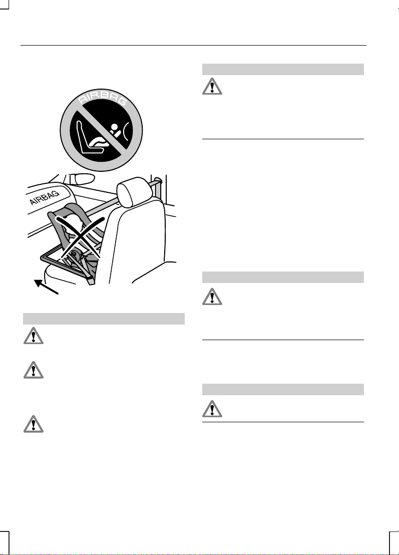
CHILD SEATS
E72336
WARNINGS
Extreme Hazard! Do not use a
child restraint on a seat
protected by an airbag in front of it!
Original text according to ECE
R94.01: Extreme Hazard! Do not
use a rearward facing child restraint
on a seat protected by an air bag in
front of it!
There is a risk of death or
serious injury when the airbag
deploys.
WARNINGS
Always have the rear row head
restraint raised when a child
restraint is being installed or
occupying the seat, provided doing
so does not move the child restraint
away from the vehicle seat.
Note:
If the vehicle has been
involved in an accident, have the child
safety seat checked by an expert as
it might be damaged.
Note:
Do not leave children
unattended in the child safety seat or
in the vehicle.
Note:
When installing a child
seat/restraint with the seat belt,
always ensure belts fit without slack
or twists.
WARNING
There is a risk of death or
serious injury when the
manufacturer’s instructions are not
followed properly or when the child
seat/restraint is modified in any way.
Whenever installing a child
seat/restraint, always read and follow
the manufacturer’s instructions.
WARNING
Do not hold a child on your lap
while the vehicle is moving.
10
Child safety
Page 13
Children of height 150 cm or under
or aged 12 years or under should be
secured in special restraints for
children, such as baby seats, child
safety seats or booster cushions in
the rear seats.
Such equipment must be suitable
and government approved
(depending on country).
A choice of ECE approved child
restraints is available at your Ford
Dealer. Please ask for the
recommended child seats. Together
with the adult seat belt, these
restraints help to provide maximum
security for the children.
Child restraints for different
mass groups
The correct restraint to be used
depends on the child’s age and
weight:
Baby safety seat
E72337
Babies under 13 kg (approximately
18 months) are best protected if
properly restrained in rearward facing
baby safety seats (Group 0+) on
the rear seat.
Child safety seat
E72338
Children weighing between 13 and
18 kg (approximately nine months to
four years old) should be carried
properly restrained in child safety
seats (Group I) in the rear seat.
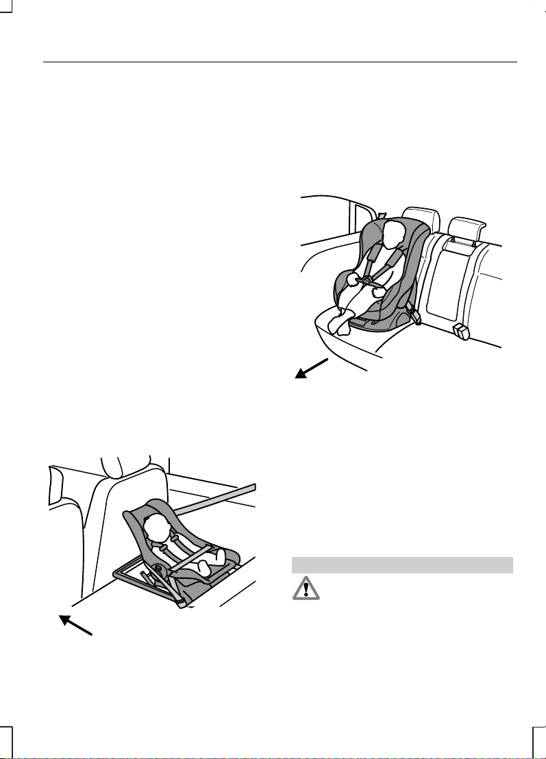
CHILD SEAT POSITIONING
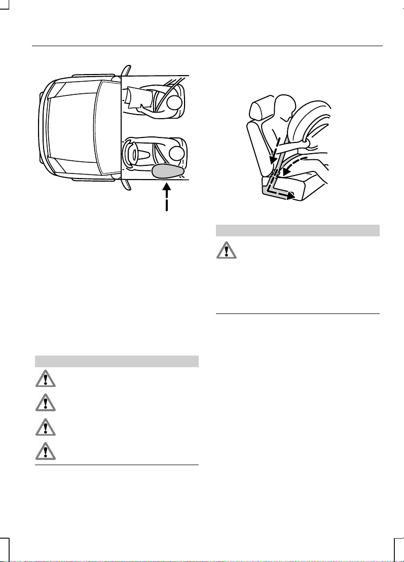
WARNINGS
If your Ford vehicle is equipped
with a front passenger airbag,
children of height 150 cm or under or
aged 12 years and under must only
be properly restrained in the rear seat
– never in the front.
11
Child safety
Page 14

WARNINGS
Extreme Hazard! Do not use a
rearward facing child restraint
on a seat protected by an airbag in
front of it!
Note:
If individual circumstances
require that a child weighing more
than 9 kg must travel in a front seat
protected by an operational front
airbag, only use a forward facing
restraint.
The following table advises on the
suitability of child restraint fitment
locations.
Child seat positions
Mass group categories
Seating positions
IIIIII0+0
22 to 36
kg
(about
6− 12
years)
15 to 25
kg
(about
31/2 − 12
years)
9 to 18
kg
(about 9
months−
4 years)
Up to 13
kg
(about
0− 2
years)
Up to 10
kg
(about
0− 9
months)
Booster
seat/
cushion
Booster
seat/
cushion
Child
safety
seat
Baby
safety
seat
Baby
safety
seat
U
1
U
1
U
1
XX
Front passenger
seat, with airbag
UUUUU
Front passenger
seat, without
airbag
UUUUURear seats
N/AN/ALLN/A
ISOfix child seat,
second row centre
X = Seat position not suitable for children in this mass/age group.
U = Seat position suitable for universal category restraints approved for use
in this mass/age group.
12
Child safety
Page 15

U1 = Seat position suitable for universal category restraints but Ford
recommends that children should be secured in an appropriate child restraint
in the rear seats.
L = Seat position suitable for particular child restraints approved for use in this
mass/age group.
N/A = Not applicable.
13
Child safety
Page 16
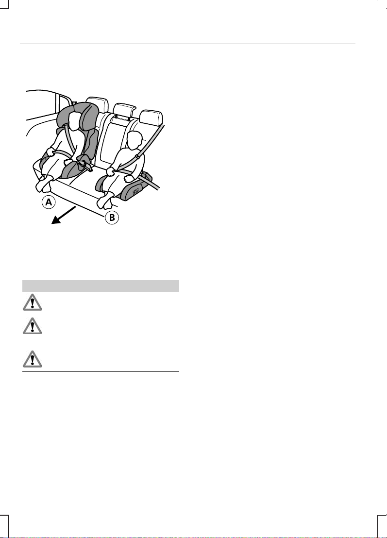
BOOSTER CUSHIONS
E72362
Booster seatA
Booster cushionB
WARNINGS
You should never use a booster
seat with only a lap belt.
Never put the shoulder belt
under a child’s arm or behind
the back.
Never use pillows, books, or
towels to boost a child.
Children weighing more than 15 kg
and under 150 cm should use a
booster seat or booster cushion.
Ford recommends using booster
seats that combine a booster
cushion and a back rest into one seat
for children between 15 and 25 kg.
The raised seating position ensures
that the adult seat belt can be
correctly guided over the centre of
the shoulder instead of along the
neck, the lap belt lying tightly across
the hips instead of the stomach.
Make sure that your child sits in an
upright position.
14
Child safety
Page 17
ISOFIX ANCHOR POINTS
Tourneo Connect
WARNINGS
Ford does not recommend the
use of an ISOfix system without
the use of an anti-rotation device,
such as a top tether anchor or
support leg, correctly installed.
There is a risk of death or
serious injury when the
manufacturers instructions are not
followed properly or when the child
restraint is modified in any way.
Your vehicle has been equipped with
ISOFIX anchor points. Your Ford
Dealer will be pleased to make them
accessible.
E75769
The ISOFIX system consists of two
rigid latching arms on the child seat
which attach to anchor points at the
bottom of the seat. When made
available by your Ford Dealer, the two
lower anchor points may be found
on the second row centre seat and
are labelled with a circular pictogram
and the text ‘ISOFIX’. The guides
enable the latching arms of an ISOFIX
child seat to be easily and securely
attached.
ISOFIX child seats not approved by
Ford have not been validated by
Ford, and neither the suitability nor
the safety of such seats can be
certified, whether installed using the
ISOFIX system or the normal seat
belts.
Attaching a child seat with top
tethers
WARNING
Attach the tether strap only to
the appropriate tether anchor
as shown. The tether strap may not
work properly if attached somewhere
other than the correct tether location.
A third anchor point has been
provided for child seats that are
equipped with a top tether, available
for use in the forward facing
configuration. This additional anchor
will enable the use of a top tether
strap. Contact your Ford Dealer to
have this anchor installed.
15
Child safety
Page 18
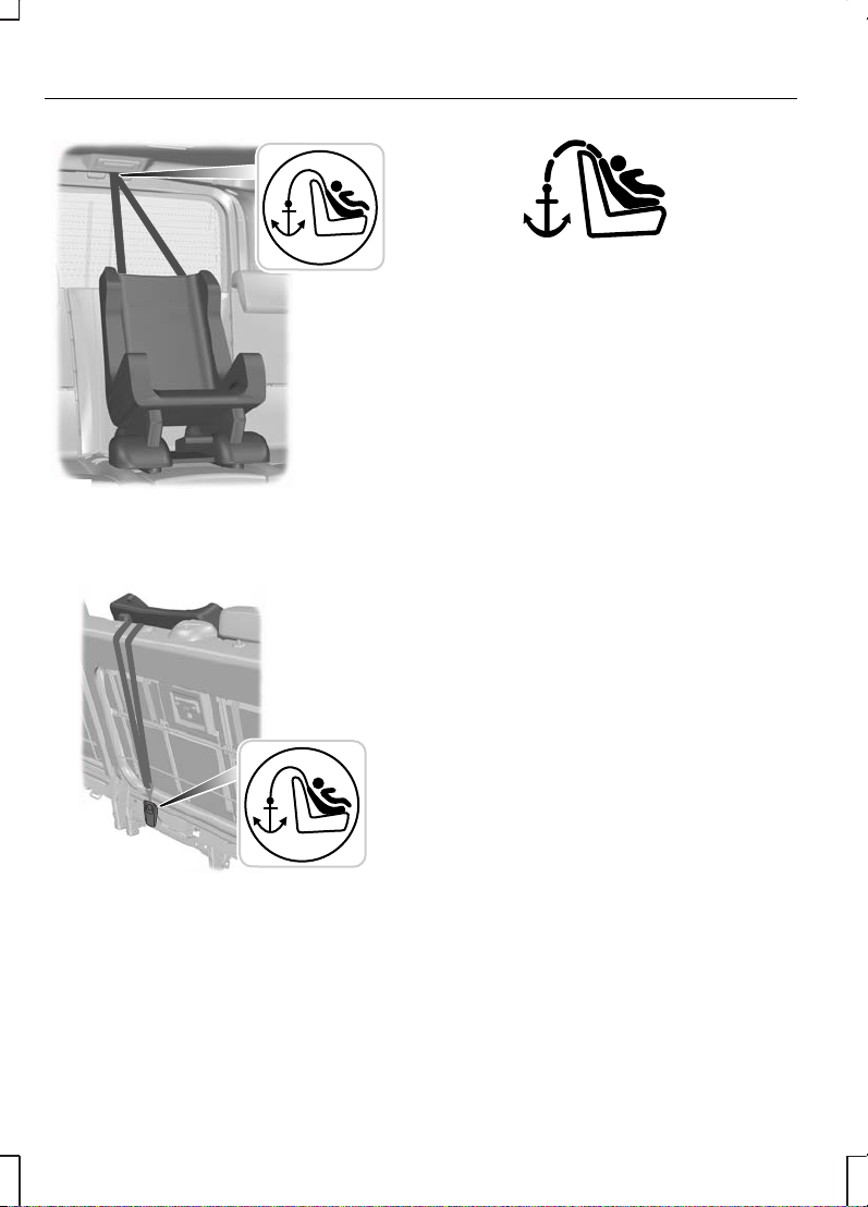
E75770
On vehicles with five seats, the
anchor is located at the top of the
rear door opening.
E75771
On vehicles with eight seats, it is
located on the rear of the second
row centre seat.
E75772
The anchor point is identified by a
pictogram. The tether strap should
be routed beneath the raised head
restraint to the anchor point. Remove
the anchor point cover and attach
the strap. After installing the child
safety seat, tighten the tether strap
according to the manufacturer’s
instructions.
16
Child safety
Page 19
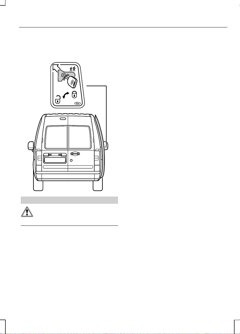
CHILD SAFETY LOCKS
Tourneo Connect
E75766
WARNING
When the child safety lock is
activated, the door can only be
opened from outside.
Note:
Child safety locks are only
fitted to sliding doors.
Using the ignition key, turn the safety
lock lever on the end of the door
outwards. The door cannot be
opened from inside the vehicle.
To deactivate the lock, turn the safety
lock lever inwards.
17
Child safety
Page 20
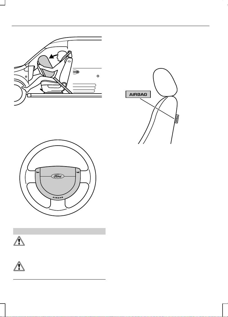
PRINCIPLE OF OPERATION
Airbags
E75574
WARNING
Do not modify the front of the
vehicle in any way, as this can
adversely affect the airbag
deployment.
Note:
A loud bang will be heard
when an airbag deploys and it is
normal to see a cloud of harmless
powdery residue.
The airbag system comprises the
following:
•
driver and front passenger
inflatable nylon bags (airbags) with
gas generators.
•
side airbags
•
curtain airbags
•
a seat belt pretensioner
•
crash sensors.
•
a warning lamp in the instrument
cluster.
•
an electronic control and
diagnostic unit.
E72330
18
Occupant protection
Page 21
WARNINGS
Repairs to either of the front
seat covers or the sensors
attached to the seats should only be
carried out by properly trained
technicians. Injuries may result if the
side airbags are triggered
inadvertently.
Do not block, obstruct or cover
the airbag because it may
prevent proper deployment. Do not
poke any sharp objects into the areas
where airbags are fitted. This could
damage the airbags.
Do not use any accessory seat
covers that are not specifically
designed for seats with side airbags.
These seat covers must be fitted by
properly trained technicians.
E66553
WARNING
Always wear the seat belt and
keep sufficient distance
between the driver and the steering
wheel. Only when the seat belt is
used properly, can it hold the body
in a position which allows the airbag
to achieve its optimum effect. There
is a risk of injury when the airbag
deploys.
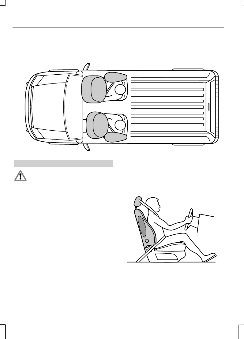
The seat and back must be set
correctly for the airbags to be
optimally effective. See Sitting in
the correct position (page 74).
This is the ideal seating position for
the driver and front passenger and
helps reduce the risk of injury from
sitting too close to an inflating airbag.
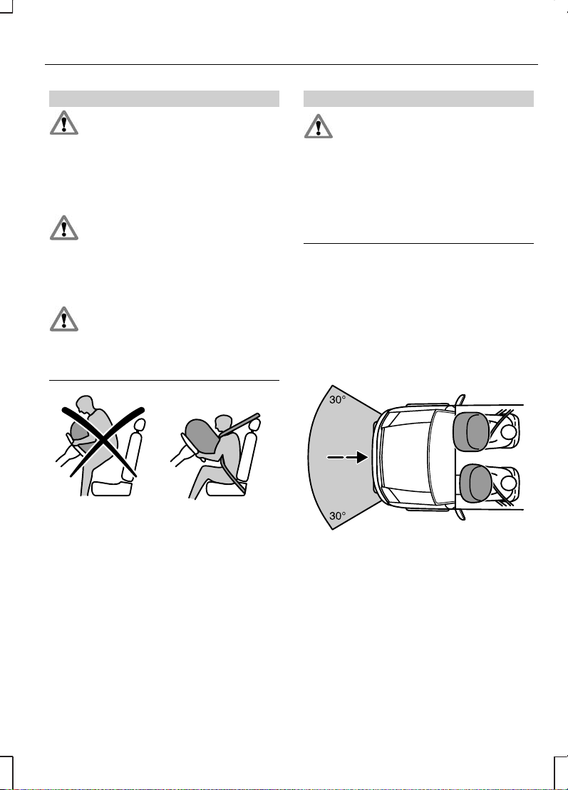
E75575
The front airbags activate during
significant collisions which are
either frontal or up to 30
degrees from the left or the right.
The airbags inflate within a few
thousandths of a second. They will
deflate on contact with the front
occupants thus cushioning forward
body movement.
19
Occupant protection
Page 22
E75576
During minor collisions as well as
overturns and rear or side collisions,
the front airbag system will not be
activated.
E75577
WARNINGS
Repairs to the steering wheel,
steering column and airbag
system should be carried out by
properly trained technicians.
Always keep the areas in front
of the airbags free. Never affix
anything to or over these areas.
These areas should only be wiped
with a damp cloth, never with a wet
cloth.
Side air bags
E72328
A label on the seatback indicates that
side airbags are fitted. The side
airbags are fitted on the side of the
seatbacks of the front seats. In case
of a severe lateral collision, the airbag
on the side affected by the collision
will be inflated.
20
Occupant protection
Page 23
E75578
The airbag will inflate between the
door panel and occupant and above
the door panel trim to provide
protection to the head and rib areas.
Once the occupant’s body contacts
the airbag, the propellant escapes,
thereby cushioning the impact.
The side airbags are not activated
upon minor lateral collisions nor upon
front or rear impacts.
Seat belts
WARNINGS
Use seat belts at all times.
Never use a seat belt for more
than one person.
Avoid wearing thick clothing.
The seat belts should fit tightly
around the body.
Seat belt pretensioner
E72333
WARNING
The belt pretensioners must not
be removed. If the
pretensioners deployed during an
accident, they must be replaced.
Have the pretensioners serviced and
disposed of by specially trained
personnel only.
The restraint system, with belt
pretensioner in the driver’s seat belt,
helps to reduce the risk of serious
injury in a major frontal impact. During
a serious crash the driver’s seat belt
is pretensioned to help reduce slack
in the belt. The safety belt
pretensioner is a device which
removes excess webbing from the
safety belt system. When the safety
belt pretensioner deploys, webbing
from the lap and shoulder belt is
tightened.
The belt pretensioner is not triggered
in any side, rear or minor frontal
collisions.
21
Occupant protection
Page 24
FASTENING THE SEAT BELTS
E66541
WARNING
Insert the tongue into the buckle
until a distinct click is heard,
otherwise the seat belt will not be
locked correctly.
Pull the belt out steadily. It may lock
if pulled sharply or if the vehicle is on
a slope.
To release the belt, press the red
button on the buckle and let the belt
rewind completely and smoothly.
Rear seat belts
E75564
WARNING
In order to ensure that the
centre belt works properly, the
rear seatback must be correctly
engaged.
Make sure that each seat belt uses
the correct buckle.
22
Occupant protection
Page 25
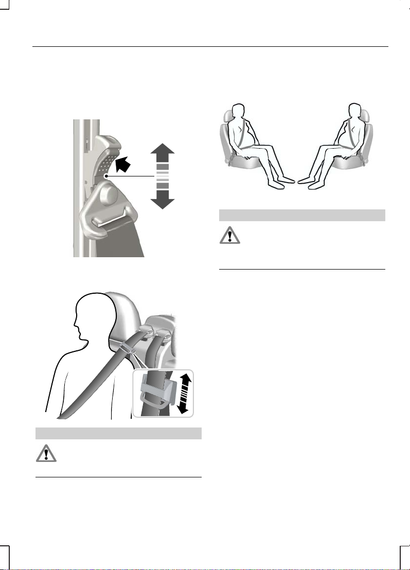
SEAT BELT HEIGHT ADJUSTMENT
Front seat belt
E68901
Rear seat belt
E73074
WARNING
Make sure that the seat belt
runs smoothly through the
guide.
USING SEAT BELTS DURING PREGNANCY
E68587
WARNING
Position the seat belt correctly
for your safety and that of your
unborn child. Do not use only the lap
strap or the shoulder strap.
Position the lap strap comfortably
across your hips and low beneath
your pregnant abdomen. Position the
shoulder strap between your breasts,
above and to the side of your
pregnant abdomen.
23
Occupant protection
Page 26
GENERAL INFORMATION ON RADIO FREQUENCIES
CAUTION
The radio frequency used by
your remote control can also be
used by other short distance radio
transmissions (e.g. amateur radios,
medical equipment, wireless
headphones, remote controls and
alarm systems). If the frequencies are
jammed, you will not be able to use
your remote control. You can lock
and unlock the doors with the key.
Note:
You could unlock the doors if
you press the buttons on the remote
control unintentionally.
The operating range between your
remote control and your vehicle
varies depending on the
environment.
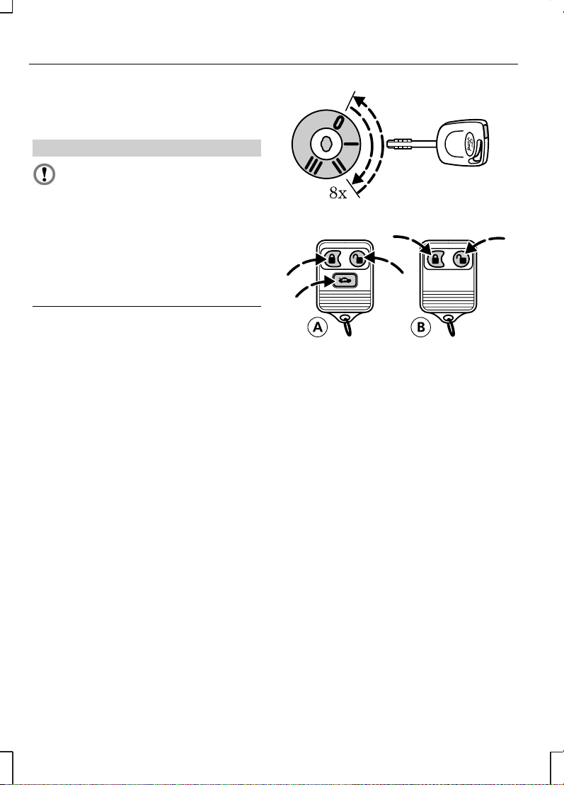
PROGRAMMING THE REMOTE CONTROL
A maximum of four remote controls
(including the ones supplied with the
vehicle) can be programmed.
E74806
Transit ConnectA
Tourneo ConnectB
Note:
Ensure that the anti-theft
alarm is deactivated and that all
doors are closed.
•
To programme new remote
controls, turn the ignition key from
position 0 to position II eight times
within 10 seconds. The ignition
must end in position II and remain
in this position. The door locks will
cycle to indicate that it is now
possible to programme new
remote controls.
•
Press any button on a new
remote control within 20 seconds
of the door locks cycling. The
door locks will cycle again to
indicate that the remote control
has been successfully
programmed.
24
Keys and remote controls
Page 27
•
Repeat step 2 for all your remote
controls, including your original
remote control. Each time a new
remote control is successfully
programmed, the programming
period starts again and it is
possible to programme a new
remote control for 20 seconds.
•
Turn the ignition to position 0. The
door locks will cycle to indicate
that the remote control
programming is ended. Only the
remote controls which you have
just programmed are now able to
lock and unlock your vehicle.
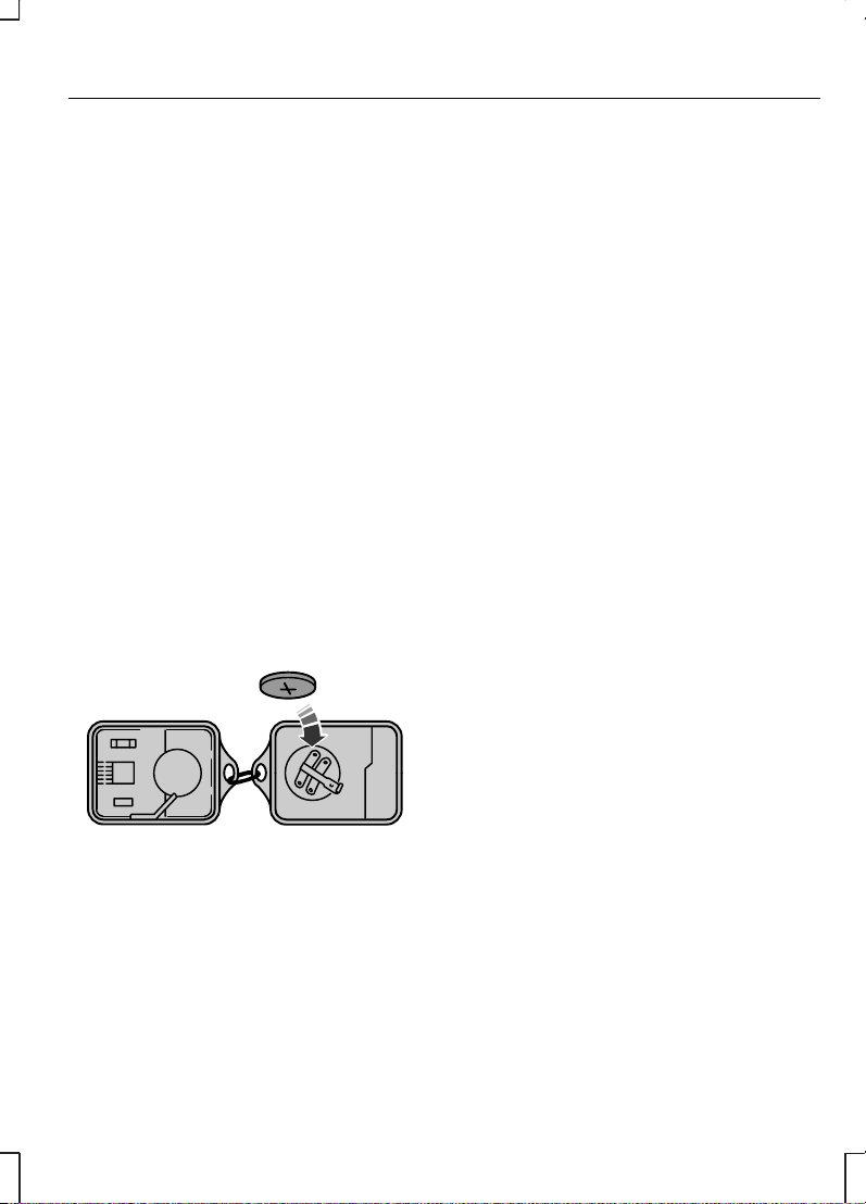
CHANGING THE REMOTE CONTROL BATTERY
If the range of the transmitter in the
key decreases gradually, the battery
(type 3V CR 2032) should be
replaced.
E66527
•
Open the transmitter unit by
separating the sides with a flat
object.
•
Carefully prise out the battery with
the flat object. Fit the new battery
between the contacts with the +
sign facing downwards.
Reassemble the transmitter unit
in reverse order.
25
Keys and remote controls
Page 28
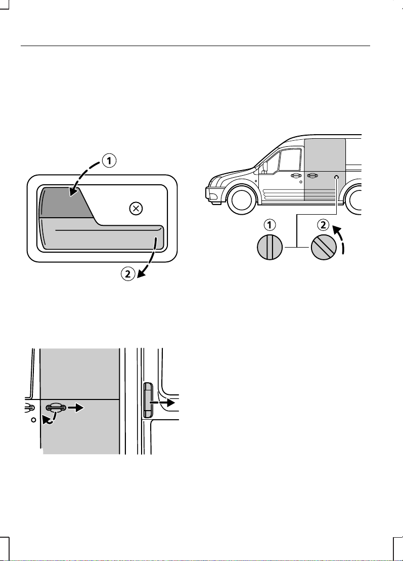
LOCKING AND UNLOCKING
Front doors
The front doors can be locked and
unlocked from the outside with the
key or the remote control.
E74704
When inside the vehicle, they can be
locked with the locking lever 1 and
unlocked using the door handle 2.
Sliding door
E74705
Note:
On Tourneo Connect, the
right-hand sliding door is inhibited
from opening fully when the fuel filler
flap is unlocked and open.
To open, pull the door handle and
then slide the door backwards.
E74706
To manually lock the sliding door, turn
the locking knob on the inside of the
door to the locked position 1. To
unlock turn it to the unlocked position
2.
26
Locks
Page 29
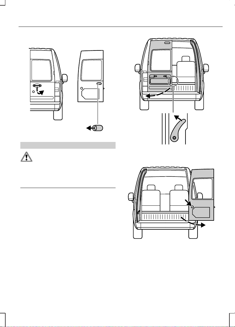
Double rear doors
E74707
WARNING
Close the rear doors properly to
prevent them from opening
while you are driving. Driving with the
rear doors open is extremely
dangerous as exhaust fumes can be
drawn into the vehicle’s interior.
To open the right-hand rear door
from the outside, pull the door
handle. To unlock and open the
right-hand door from the inside, push
the emergency release lever to the
left.
E74708
To open the left-hand rear door, pull
the door handle.
E74709
Both doors can be opened through
180 degrees. Once the 90 degree
position is reached, push the yellow
button located on the door. The
check arms will automatically
re-engage when the doors are
closed.
27
Locks
Page 30
E74710
Some models have rear doors that
can be opened through 250
degrees. Once the 90 degree
position is reached, push the yellow
button located on the door. The
check arms will automatically
re-engage when the doors are
closed.
Tailgate
E66517
B
A
WARNING
Close the tailgate properly to
prevent it opening while you are
driving. Driving with the tailgate open
is extremely dangerous as exhaust
fumes can be drawn into the
vehicle’s interior.
To open, pull the door handle A
located above the number plate. The
tailgate can be opened from inside
by moving the release button B
upwards, which is accessible through
the aperture at the bottom of the
tailgate.
Central locking
E74798
28
Locks
Page 31

WARNING
If a failure occurs in the vehicle’s
electrical system the front doors
or the rear door can still be individually
unlocked with the key.
The central locking system can be
activated from the driver's or front
passenger's door. It can also be
activated from the rear doors or
tailgate.
The central locking system can be
deactivated from the driver's or front
passenger's door.
Make sure all doors are fully closed
to ensure proper locking.
The locking system is activated from
the outside with the key or the
remote control. From the inside it is
activated with the locking lever above
the door opening lever on the front
doors.
The sliding door can be locked
separately from the inside with the
locking knob on the door.
Unlocking the rear door with a key
will only unlock that door.
Double locking
E74799
WARNING
Double locking should not be
activated when people are
inside the vehicle.
Double locking is an additional theft
protection feature which prevents
the vehicle’s doors from being
opened from inside the vehicle.
Double locking is possible only if all
doors are closed.
Unlocking the vehicle
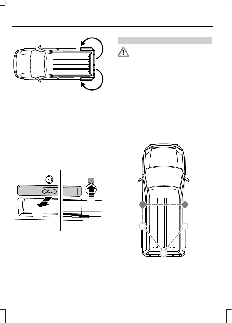
Transit Connect
Once any door is unlocked, the
direction indicators will flash once
as confirmation.
29
Locks
Page 32

E74800
With the key: Turn the key in the
driver’s or front passenger's door to
position 1 to unlock the front doors.
Turn the key in the driver’s or front
passenger's door to position 1 twice
to unlock all doors.
Turn the key in the rear door
clockwise to unlock the rear door
only.
E74801
With the remote control: Press
the unlock button once to unlock the
front doors only or press the unlock
button twice within 3 seconds to
unlock all doors.
E66522
Press the unlock button once to
unlock the rear doors and the sliding
door.
Tourneo Connect
E74800
To unlock all doors and disarm the
anti-theft alarm system:
30
Locks
Page 33

With the key: Turn the key in the
driver’s or front passenger's door to
position 1 to unlock the front doors.
E74802
With the remote control: Press
the unlock button once.
The direction indicators will flash
once as confirmation.
Locking the vehicle
E74803
To activate central locking and arm
the anti-theft alarm system:
With the key: Turn the key in the
driver's or front passenger's door to
position 2.
E66524
With the remote control: Press
the lock button once.
On vehicles without double locking,
the direction indicators will flash
twice as confirmation.
E74805
To activate double locking and arm
the anti-theft alarm system:
31
Locks
Page 34

With the key: Turn the key in the
driver's or passenger's door to
position 1 and then to position 2
within three seconds.
Central/double locking can also be
activated from the rear door by
turning the key in the same direction
as shown for the front right-hand
door.
E66521
With the remote control: Press
the lock button twice within three
seconds.
The direction indicators will flash
twice as confirmation.
The anti-theft alarm system can also
be armed independently from the
double locking system by turning the
door key to position 2.
32
Locks
Page 35

PRINCIPLE OF OPERATION
The engine immobilisation system is
a theft protection feature which
prevents the engine from being
started with an incorrectly coded key.
CODED KEYS
E66506
Your vehicle is supplied with coded
keys.
WARNING
If a key is lost, it is imperative to
erase and recode the remaining
keys. Consult your dealer if you now
have only one valid key.
Replacement keys must be recoded
together with your other keys.
In case of loss, replacement keys are
available from dealers by stating the
key number shown on the tag
provided with the original keys.
Note:
To ensure a trouble’free data
exchange between the vehicle and
key, do not shield the keys with any
metal objects.
E66505
Key coding
A maximum of eight keys (including
the ones supplied with the vehicle)
can be coded using two other keys
previously coded for your vehicle.
Complete each of the following steps
within five seconds.
E66507
1. Insert the first key in the ignition
switch and turn to position II.
2.
Turn the key back to position 0
and remove from the ignition
switch.
33
Engine immobiliser
Page 36

3. Insert the second key in the
ignition switch and turn to position
II.
4. Turn the second key back to
position 0 and remove from the
ignition switch − the key coding
mode is now activated.
5. If an uncoded key is now inserted
in the ignition switch and turned
to position II within 10 seconds,
this key is coded to the system.
6. After the coding process is
completed, remove the key from
the ignition switch. Wait five
seconds for the system to be
activated.
If coding is not completed correctly,
the indicator light flashes after the
ignition is switched on with the newly
coded key and the engine will not
start.
Repeat the coding process after
waiting 20 seconds with the ignition
switched on (position II).
Coding erasure
With two keys coded for your vehicle
you can make all the other coded
keys unusable, e.g. after loss:
Complete each of the following steps
within five seconds.
Carry out the first four steps under
Key coding, then continue as
follows:
E66508
•
Insert the second key in the
ignition switch and turn to position
II.
•
Remove the key from the ignition
switch.
•
Insert the first key in the ignition
switch, turn to position II and hold.
The control light flashes for five
seconds.
•
If the ignition is switched off during
these five seconds, the erasure
process is terminated and no key
is erased.
•
If the erasure process is
completed, all the other keys,
apart from the two used for
erasure, can no longer be used
unless recoded.
Additional keys can now be coded.
ARMING THE ENGINE IMMOBILISER
The engine immobiliser is armed
automatically five seconds after you
have switched the ignition off. The
indicator in the instrument cluster will
flash to confirm that the system is
operating.
34
Engine immobiliser
Page 37

DISARMING THE ENGINE IMMOBILISER
The engine immobiliser is disarmed
automatically when you switch the
ignition on with a correctly coded key.
The indicator in the instrument cluster
will come on for approximately three
seconds and then go out. If the
indicator stays on for one minute or
flashes for approximately one minute
and then repeatedly at irregular
intervals, your key has not been
recognised. Remove the key and try
again.
If you attempt to start the engine with
an incorrectly coded key, you will
need to wait for approximately 20
seconds before attempting to start
the engine again with a correctly
coded key. If you are unable to start
the engine with a correctly coded
key, this indicates a malfunction.
Have this checked immediately.
35
Engine immobiliser
Page 38

ARMING THE ALARM
The system is armed as soon as the
vehicle is locked and acts as a
deterrent to unauthorised persons
who attempt to open the doors,
bonnet or luggage compartment, or
remove the audio system.
Automatic arming delay
The 20 seconds arming delay begins
when the bonnet, luggage
compartment and all doors are
closed and locked.
Alarm
The alarm sounds for 30 seconds if
an unauthorised person opens a
door, the load compartment or the
bonnet. The hazard warning flashers
will flash for five minutes.
Any attempt to start the engine or to
remove the audio system sounds the
alarm again.
DISARMING THE ALARM
The anti-theft alarm system can be
deactivated at any time − even when
the alarm is sounding − by unlocking
one of the front doors.
The anti-theft alarm system is
deactivated when the luggage
compartment is unlocked with a key.
After closure, the alarm is once again
armed.
36
Alarm
Page 39

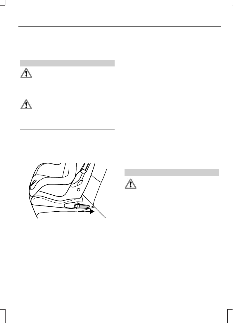
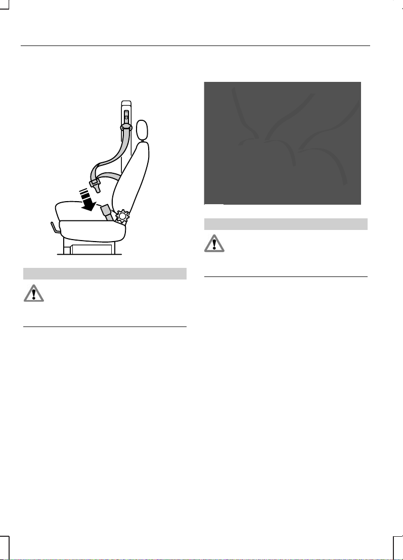
ADJUSTING THE STEERING WHEEL
E70358
WARNING
Never adjust the steering wheel
when the vehicle is moving.
Release the locking lever to adjust
the height of the steering wheel and
its distance from the driver.
Return the lever to its original position
to secure the wheel.
See Sitting in the correct
position (page 74).
AUDIO CONTROL
Select radio, CD or cassette mode
on the audio unit.
The following functions can be
operated with the remote control:
Volume
E70361
Volume up: Pull the VOL+ switch
towards the steering wheel.
Volume down: Pull the VOL− switch
towards the steering wheel.
Seek
E70362
Move the SEEK switch towards the
steering wheel or the instrument
panel:
•
In radio mode, this will locate
the next radio station up or down
the frequency band.
•
In CD mode, it will select the
next or previous track.
37
Steering wheel
Page 40

Mode
E70363
Briefly press the button on the side:
•
In radio mode, this will locate
the next pre-set radio station.
•
In CD mode, this will select the
next CD if a CD changer is fitted.
•
In all modes to abort a traffic
message during broadcasting.
Press and hold the button on the
side:
•
In radio mode, to change the
waveband.
38
Steering wheel
Page 41

WINDSCREEN WIPERS
E65995
A
B
C
D
Single wipeA
Intermittent wipingB
Normal wipingC
High speed wipingD
WINDSCREEN WASHERS
E74364
WARNING
Do not operate the washer for
more than 10 seconds at a time,
and never when the reservoir is
empty.
Press the knob at the end of the lever
and hold it to operate the windscreen
washers.
The washer will operate in
conjunction with the wipers.
REAR WINDOW WIPER AND WASHERS
Intermittent wiping
E65996
Pull the lever towards the steering
wheel.
39
Wipers and washers
Page 42

Washer
E74365
WARNING
Do not operate the washer for
more than 10 seconds at a time,
and never when the reservoir is
empty.
Pull the lever fully towards the
steering wheel and hold it to operate
the washer.
The washer will operate in
conjunction with the wipers.
ADJUSTING THE WINDSCREEN WASHER JETS
E73425
The eye ball jets can be adjusted
precisely using a pin.
CHECKING THE WIPER BLADES
E66644
Run the tip of your fingers over the
edge of the blade to check for
roughness.
Clean the wiper blade lips with water
applied with a soft sponge.
40
Wipers and washers
Page 43

CHANGING THE WIPER BLADES
E66645
5
2
4
3
1
1. Lift the wiper arm.
2. Position the wiper blade at a right
angle to the wiper arm (1).
3. Press the retaining clip in the
direction of the arrow (2).
4. Disengage the wiper blade from
the arm (3).
5.
Move the blade sideways (4).
6.
Pull the blade off the arm (5).
Install in the reverse order.
41
Wipers and washers
Page 44

LIGHTING CONTROL
Lighting control positions
A
D
B
C
E65986
OffA
Side and tail lampsB
HeadlampsC
Front fog lampsD
Main/dipped beam
E65987
To switch over pull the lever towards
the steering wheel.
Headlamp flasher
E65987
Pull the lever slightly towards the
steering wheel.
FRONT FOG LAMPS
E65988
1
2
Switch on the headlamps 1 and pull
out the control switch one position
2.
The front fog lamps should be used
only when visibility is considerably
restricted by fog, snow or rain.
REAR FOG LAMPS
E65989
1
2
42
Lighting
Page 45

WARNING
The rear fog lamps may only be
used when visibility is restricted
to less than 50 m and must not be
used when it is raining or snowing.
Note:
On vehicles not equipped with
front fog lamps the control switch
can be pulled out only one position.
Switch on the exterior lamps 1 and
pull out the control two positions 2.
HEADLAMP LEVELLING
All vehicles
The level of the headlamp beams can
be adjusted according to the vehicle
load. Turn the thumbwheel
downward to lower the beams, and
upward to raise them.
E65990
Transit Connect
E74263
Without headlamp levellingA
With headlamp levellingB
43
Lighting
Page 46

Recommended headlamp levelling control positions
Control positionLoad
T220/
T230
T210T200Load in luggage
compartment
1
Persons
000-1
1.53/2
4
1.52
max.
2
1
1
When the vehicle is fitted with the attitude/ride height pack, headlamp levelling
may need to be adjusted.
2
See Technical specifications. See Technical specifications (page 133).
3
Long wheelbase.
4
Short wheelbase.
Higher control positions (+1) may be necessary when towing a trailer.
Tourneo Connect
E74264
Without headlamp levellingA
With headlamp levellingB
44
Lighting
Page 47

Recommended headlamp levelling control positions
Control positionLoad
K230K220K200/
K210
Load in luggage
compartment
1
Persons
RearFront
000--1-2
00.50-12
00.5
02/0.5
3
-32
1.53/2.5
2
1
12/1.5
3
max.
1
32
22/2.5
3
2.5
22/2.5
3
max.
1
-1
1
See Technical specifications. See Technical specifications (page 133).
2
Long wheelbase.
3
Short wheelbase.
Higher control positions (+1) may be necessary when towing a trailer.
HAZARD WARNING FLASHERS
E74367
Press the switch to turn on or off. The
hazard warning flashers can also be
operated when the ignition is off.
45
Lighting
Page 48

DIRECTION INDICATORS
E74363
INTERIOR LAMPS
A
B C
E72170
OffA
Door contactB
OnC
With the switch in position B, the
interior lamps illuminate when the
doors are unlocked (central locking
only) with the key or the remote
control or when the door is opened.
On some models, with the switch in
position B, the interior lamps will stay
on for a while after the doors are
shut. They will switch off immediately
when the ignition is switched on or
the doors are locked.
With the switch in position C and the
ignition off, the interior lamps will
switch off automatically after
approximately 30 minutes.
To switch the lamps back on switch
on the ignition (position II) for a short
time or close and re-open the driver's
door.
Reading lamps
E72171
46
Lighting
Page 49

CHANGING A BULB
WARNINGS
During operation, the bulbs and
their surroundings get hot.
Switch off the lamps and let the bulbs
cool down before replacing them.
Have the headlamp alignment
checked by an expert after
each replacement of a bulb.
Always switch off lamps and ignition
before replacing any bulb.
Never touch the glass of the bulbs.
Fit only bulbs having a UV filter.
Always replace a faulty bulb with a
new one of the same type.
When replacing a bulb, clean the
headlamp lens with a damp cloth to
avoid any electrostatic charging,
which attracts dust to the plastic lens.
After replacing a bulb, check that the
lamps operate correctly.
Front direction indicators
E76059
21 watt spherical bulb, orange
Turn the bulb holder anticlockwise
and pull out. Turn the bulb under
slight pressure anticlockwise and
remove it. Replace the bulb. When
installing in the reverse order, pay
attention to the guide tabs.
Headlamps
Opening the headlamp
assembly
E76060
47
Lighting
Page 50

Turn the cover anticlockwise and
remove. When installing in the
reverse order, make sure the arrow
on the cover faces up.
Side lamp
E76061
5 watt wedge base bulb
Remove the cover and pull out the
socket. Pull out the bulb and replace
it. Install in the reverse order.
Headlamp - dipped/main beam
E76062
H4, 55/60 watt halogen bulb
Pull off the wiring connector.
Disengage the wire clip and pull out
the bulb. Replace the bulb. When
installing in the reverse order, make
sure the wire clip engages properly
to bulb housing.
Side repeater indicator
E76063
5 watt wedge base bulb
Turn the complete lamp assembly
clockwise and pull it out. Grasp the
bulb holder, turn the lamp housing
anticlockwise and remove it. Pull the
bulb out and replace it. Install in the
reverse order.
48
Lighting
Page 51

Fog lamps
E76064
H11, 55 watt halogen bulb
Reach behind the bumper and pull
off the wiring connector. Turn the
bulb holder anticlockwise and pull it
out. Replace the bulb with the
integrated bulb holder. Install in the
reverse order.
Rear lamps
E76065
E76066
Tail/brake lamp 5/21 wattA
Direction indicator 21 wattB
Reversing lamp 21 wattC
Rear fog lamp 21 wattD
Open the rear doors and remove the
two nuts securing the lamp.
Withdraw the rear lamp assembly
from the vehicle and unclip the bulb
carrier. Gently press the bulb into the
bulb holder, turn anticlockwise,
remove and replace the bulb. Install
in the reverse order.
49
Lighting
Page 52

Central brake lamp
E76067
16 watt wedge base bulb
Remove the nuts securing the lamp.
Withdraw the lamp assembly from
the vehicle. Pull the bulb out and
replace it. Install in the reverse order.
Number plate lamp
Vehicles with a tailgate
2
1
E66620
10 watt bayonet bulb
Open the lens, remove and replace
the bulb. Install in the reverse order.
Vehicles with double rear
doors
E66619
5 watt wedge base bulb
Carefully prise the cap from the lamp
with a suitable screwdriver and pull
the bulb out of the holder. Install in
the reverse order.
50
Lighting
Page 53

Interior lamps
Front
E76068
10 watt festoon bulb
Switch off the interior lamps. Prise out
the lamp assembly with a flatbladed
screwdriver at the side opposite the
switch. Remove and replace the
bulb. Install in the reverse order.
Rear
E76070
10 watt festoon bulb
Carefully prise out the lamp assembly
and remove the bulb. Fit new bulb in
the reverse order.
Reading lamps
E76069
5 watt spherical bulb
Switch off the interior lamps. Prise out
the lamp assembly with a flatbladed
screwdriver at the side opposite the
switch. Remove and replace the
bulb. The bulbs can be replaced after
the contact plate has been hinged
back.
51
Lighting
Page 54

ELECTRIC WINDOWS
WARNING
Before operating the electric
windows you should verify they
are free of obstructions and ensure
that children and/or pets are not in
the proximity of window openings.
Failure to do so could result in serious
personal injury. It is the primary
responsibility of the supervising adults
to never leave a child unattended in
a vehicle and to never leave the keys
in an unattended vehicle.
Note:
When the switches are
operated often during a short period
of time, the system might become
inoperable for a certain time to
prevent damage due to overheating.
Switch on the ignition to operate the
electric windows.
A
B
E68836
Press to openA
Press to closeB
To open the driver’s
window automatically
Momentarily press A. Press A again
to stop the window.
EXTERIOR MIRRORS
E71273
A
Convex mirrorA
WARNING
Do not over estimate the
distance of the objects that you
see in the convex mirrors. Objects
seen in convex mirrors will appear
smaller and further away than they
actually are.
The mirrors increase your rearward
field of vision to reduce the so-called
blind spot at the rear quarter of your
vehicle.
52
Windows and mirrors
Page 55

E71274
Make sure that you fully engage the
mirror in its support when returning
it to its original position.
ELECTRIC EXTERIOR MIRRORS
E71280
B
C
A
Left-hand mirrorA
OffB
Right-hand mirrorC
E71281
D
E
F
G
UpA
RightB
DownC
LeftD
The electric exterior mirrors are fitted
with a heating element that will
defrost or demist the mirror glass.
See Heated windows and
mirrors (page 65).
INTERIOR MIRROR
E71272
Dip the mirror to reduce glare when
driving at night.
53
Windows and mirrors
Page 56

REAR QUARTER WINDOWS
E66498
Pull the lever outwards to open the
window. Press the lever in the middle
to engage it in its catch. Pull the lever
in the middle to close the window.
Push it backwards until it engages in
its catch.
54
Windows and mirrors
Page 57

INSTRUMENT PANEL OVERVIEW
Left-hand drive
E74266
Lighting control/front fog lamps/rear fog lamps. See Lighting (page
42).
A
Multi−function lever: direction indicators, main beam. See Lighting
(page 42).
B
55
Instruments
Page 58

Horn.C
Instrument cluster. See Instruments (page 55).
D
Digital clock. See Clock (page 82).
E
Wiper lever. See Wipers and washers (page 39).
F
Air vents. See Air vents (page 65).
G
Hazard warning flasher switch. See Hazard warning flashers
(page 45).
H
Audio equipment. See separate handbook.I
Climate controls. See Climate control (page 64).
J
Heated windscreen/heated rear window switches. See Climate
control (page 64).
K
Ashtray/storage. See Convenience features (page 82).
L
Recirculated air/air conditioning switches. See Climate control
(page 64).
M
Cigar lighter/auxiliary power socket. See Convenience features
(page 82).
N
Ignition switch. See Ignition switch (page 88).
O
Steering wheel adjustment. See Adjusting the steering wheel
(page 37).
P
Audio control. See Audio control (page 37).
Q
Fuses. See Fuses (page 103).
R
Headlamp levelling control. See Headlamp levelling (page 43).
S
56
Instruments
Page 59

Right-hand drive
E74267
Audio equipment. See separate handbook.A
Hazard warning flasher switch. See Hazard warning flashers
(page 45).
B
Air vents. See Air vents (page 65).
C
57
Instruments
Page 60

Multi−function lever: direction indicators, main beam. See Lighting
(page 42).
D
Instrument cluster. See Instruments (page 55).
E
Horn.F
Digital clock. See Clock (page 82).
G
Wiper lever. See Wipers and washers (page 39).
H
Headlamp levelling control. See Headlamp levelling (page 43).
I
Lighting control/front fog lamps/rear fog lamps. See Lighting (page
42).
J
Ignition switch. See Ignition switch (page 88).
K
Steering wheel adjustment. See Adjusting the steering wheel
(page 37).
L
Audio control. See Audio control (page 37).
M
Cigar lighter/auxiliary power socket. See Convenience features
(page 82).
N
Ashtray/storage. See Convenience features (page 82).
O
Heated windscreen/heated rear window switches. See Climate
control (page 64).
P
Recirculated air/air conditioning switches. See Climate control
(page 64).
Q
Climate controls. See Climate control (page 64).
R
58
Instruments
Page 61

GAUGES
E74268
Engine coolant temperature gaugeA
TachometerB
SpeedometerC
Fuel gaugeD
Toggle and reset buttonE
Clock, odometer and tripmeterF
Digital clock set buttonG
Engine coolant temperature
gauge
At normal operating temperature, the
needle remains within the centre
section.
If the needle enters the red section,
the engine is overheating. A fail safe
cooling system is activated which
allows the vehicles to be driven
temporarily.
59
Instruments
Page 62

Tachometer
On vehicles with a diesel engine, the
tachometer goes to 5 000
revolutions per minute.
Fuel gauge
The arrow adjacent to the fuel pump
symbol indicates on which side of the
vehicle the fuel filler cap is located.
Odometer
E74269
Registers the total distance of the
vehicle.
To toggle between odometer and
tripmeter, briefly press the toggle and
rest button E.
Tripmeter
E74270
The tripmeter can register the
distance of individual journeys. To
reset, press and hold the toggle and
reset button E for two seconds.
Digital clock
See Clock (page 82).
WARNING LAMPS AND INDICATORS
The following warning lamps and
indicators illuminate when the ignition
is switched on to confirm that the
system is operational:
•
ABS
•
Airbag
•
Brake system
•
Engine
•
Engine immobiliser
•
Ignition
•
Low fuel level warning lamp
•
Multi-function
•
Oil pressure
•
Traction control
•
Water trap warning lamp
If a warning lamp or indicator does
not illuminate when the ignition is
switched on, it indicates a
malfunction. Have the system
checked by an expert.
ABS warning lamp
If the ABS warning lamp
illuminates when driving, it
indicates a malfunction.
Have this checked by an expert.
Normal braking (without ABS) will be
maintained.
60
Instruments
Page 63

Airbag warning lamp
When the ignition is
switched on (position II), the
lamp illuminates briefly to
confirm that the system is
operational. If it does not illuminate, if
it stays on or illuminates intermittently
or continuously while driving, it
indicates a malfunction. Have this
checked by an expert for your own
safety.
Brake system warning lamp
WARNING
If it illuminates after releasing the
parking brake or when driving,
have the braking system checked by
an expert immediately.
Illuminates when the parking
brake is applied.
Brake system and ABS
warning lamps
WARNING
Reduce vehicle speed gradually.
Use the brake with great care.
Do not step on the brake pedal
abruptly.
If both warning lamps illuminate at the
same time, stop the vehicle as soon
as it is safe to do so. Have the
braking system checked by an
expert before continuing your
journey.
Direction indicator
Flashes during operation. A
sudden increase in the rate
of flashing warns of a failed
indicator bulb.
Engine warning lamp
Vehicles with a petrol engine
The engine warning lamp
should extinguish as soon
as the engine starts. If it
illuminates with the engine running, it
indicates a malfunction. Have this
checked by an expert as soon as
possible. If it flashes, when driving,
reduce the vehicle speed
immediately. If it continues to flash,
avoid heavy acceleration or
deceleration. Have your vehicle
checked by an expert immediately.
Vehicles with a diesel engine
Note:
The engine warning lamp also
functions as a glow plug indicator
lamp. See Starting a diesel
engine (page 89).
If it illuminates with the
engine running, it indicates
a malfunction. Have this
checked by an expert as soon as
possible. If it flashes, when driving,
reduce the vehicle speed
immediately. If it continues to flash,
avoid heavy acceleration or
deceleration. The engine will continue
to operate but it will have limited
engine power. Have your vehicle
checked by an expert immediately.
61
Instruments
Page 64

Ignition warning lamp
WARNING
If the charging system drive belt
on the diesel engines is loose,
torn or broken, the servo assistance
for the braking system also no longer
operates.
If it illuminates whilst driving,
switch off all unnecessary
electrical equipment and
drive immediately to the nearest
expert.
Low fuel level warning lamp
E75774
When the warning light illuminates,
refuel as soon as possible.
Main beam indicator
Illuminates when the
headlamps are on main
beam or when the
headlamp flasher is used.
Multi-function warning lamp
If it illuminates when driving,
it indicates a malfunction.
Have this checked by an
expert as soon as possible.
Oil pressure warning lamp
If the lamp stays on after
starting or illuminates during
a journey, stop immediately,
switch off the engine and check the
engine oil level. See Engine oil
check (page 114). Top up straight
away if the level is low.
Traction control (BTCS)
indicator
When the ignition is
switched on (position II), the
indicator illuminates briefly to
confirm that the system is
operational. While driving, the
indicator flashes during activation of
the system. After switching on the
ignition, if the indicator does not
illuminate or illuminates continuously
while driving, it indicates a
malfunction. During a malfunction,
the system switches off. Have the
system checked by an expert.
Water trap warning lamp
If it illuminates when driving,
have the water drained from
the fuel filter by an expert as
soon as possible.
62
Instruments
Page 65

AUDIBLE WARNINGS AND INDICATORS
Lights on
A warning tone will sound if the
driver's door is opened when the
lights are on and the ignition is
switched off.
63
Instruments
Page 66

PRINCIPLE OF OPERATION
Outside air
Always keep the air intakes forward
of the front windscreen free of snow,
leaves etc., to allow the system to
function effectively.
Recirculated air
Note:
It is not recommended to use
recirculated air for more than 30
minutes as there is no air exchange
and the windows may mist up.
When recirculated air is selected, only
the air currently in the passenger
compartment will be circulated.
Outside air will not enter the vehicle.
Fresh air filter
The fresh air filter removes most
potentially harmful particles such as
pollen, industrial fallout and road dust
from the air entering the vehicle’s
interior.
In an automatic car wash, you should
switch off the ventilation blower to
prevent the filter collecting wax
deposits.
Blower
The blower motor may emit noises.
Heating
The heating depends upon the
coolant temperature and is therefore
only effective when the engine is
warm.
Air conditioning
Note:
The air conditioning system
only operates when the temperature
is above +4 ºC, the engine is running
and the blower is switched on.
Operating the air conditioning leads
to higher fuel consumption.
The air is directed through the
coolant heat exchanger where it is
cooled if the air conditioning is
switched on. In addition, humidity is
extracted from the air to help keep
the windows free of mist.
The resulting condensation is
directed to the outside of the vehicle.
It is therefore quite normal if you
notice a small pool of water
underneath the parked vehicle.
General notes on
controlling the climate in
the vehicle’s interior
Close all the windows completely.
To warm the interior effectively, direct
the heated air to the footwell area. In
cold or humid weather, direct some
of the air towards the front
windscreen and side windows.
To cool the interior effectively, direct
the cooled air towards the face level.
64
Climate control
Page 67

AIR VENTS
E74362
HEATED WINDOWS AND MIRRORS
Heated windows
Use for quick defrosting or demisting
of the windscreen or rear window. It
should be switched on only if
necessary.
Heated windscreen
E74670
The system operates only when the
engine is running and also defrosts
the front washer jets. Press the
switch to turn on or off. The lamp in
the switch indicates operation.
The heating system switches off
automatically after a short period of
time.
Heated rear window
E74671
Switch on the ignition first.
Press the switch to turn on or off. The
lamp in the switch indicates
operation.
The heating system switches off
automatically after a short period of
time.
Heated exterior mirrors
Electrically operated door mirrors also
have a heating element to clear the
glass. This system operates when
the heated rear window is switched
on.
65
Climate control
Page 68

MANUAL CLIMATE CONTROL
Air distribution control
E74660
Face levelA
Face level and footwellB
FootwellC
Footwell and windscreenD
WindscreenE
The air distribution control can be set
to any position between the symbols.
A minor portion of the air stream is
always directed towards the
windscreen.
Temperature control
E74658
ColdBlue
WarmRed
Blower
E74659
OffA
To increase the blower speed, select
a higher position.
With the blower turned off, the
windscreen may mist up.
66
Climate control
Page 69

Recirculated air
E74661
Press the switch to toggle between
outside air and recirculated interior
air. The light in the switch indicates
operation.
Rapid windscreen
defrosting/demisting
E74664
Recirculated air is switched off
automatically. If necessary turn the
heated windows on. See Heated
windows and mirrors (page 65).
Rapid heating of vehicle
interior
E74662
Ventilation
E74663
Set the air distribution control to face
level or face level and footwell. Set
the blower to any position. Open the
air vents to suit individual
requirements.
Air conditioning
Switching the air conditioning
on and off
E74665
67
Climate control
Page 70

Note:
For the air conditioning to
operate the engine must be running.
Press the switch to turn on or off. The
lamp in the switch indicates when air
conditioning is selected.
If the blower is turned to position 0,
the air conditioning will turn off. When
the blower is turned on again, the air
conditioning will reactivate
automatically.
Cooling with outside air
E74667
Switch the air conditioning on.
Rapid cooling of the vehicles
interior
E74668
Switch the air conditioning on.
Windscreen
defrosting/demisting
E74666
Outside air will flow into the vehicle.
As long as the air distribution control
is set to windscreen, recirculated air
cannot be selected and the air
conditioning will be turned on
automatically. Make sure the blower
is on.
The lamp in the A/C switch
illuminates during
defrosting/demisting.
If the A/C switch is pressed the lamp
in the switch will extinguish but the
air conditioning cannot be switched
off while the air distribution control is
set to windscreen.
Reducing air humidity
E74669
68
Climate control
Page 71

Switching the air conditioning on
extracts humidity from the air and
demists the windows faster.
AUXILIARY HEATER
General information
WARNINGS
Do not operate the
programmable fuel fired heater
at filling stations, near sources of
combustible vapours or dust or in
enclosed spaces.
Do not refuel when the
programmable fuel fired heater
display is on.
Note:
The programmable fuel fired
heater will switch off automatically
when the battery voltage is low.
Note:
All symbols on the display will
flash if the power to the
programmable fuel fired heater has
been interrupted. The heater will not
operate under these circumstances.
Re-set the clock time.
Note:
The programmable fuel fired
heater will shut down in the event of
a malfunction. Have the system
checked by an expert.
Observe the following information:
•
Switch the programmable fuel
fired heater on for approximately
10 minutes at least once a month,
all year round. This prevents the
water pump and heater motor
from seizing.
•
To avoid corrosion, make sure the
coolant in your vehicle contains at
least 10 % antifreeze all year
round.
•
Make sure the coolant level is
between the MAX and MIN
marks on the reservoir to prevent
air locks. See Engine coolant
check (page 115).
•
Programmable blower operation
begins when the coolant reaches
a certain temperature. In this
mode, ambient temperature has
no effect.
•
In continuous heater operation,
the unit senses the ambient
temperature. If this is above 5°C
the programmable fuel fired
heater heater will not activate.
The programmable fuel fired heater
operates independently of the vehicle
heater by heating the engine’s
coolant circuit. It is fed from the
vehicle fuel tank. It may also be used
while the vehicle is in motion to help
the vehicle heater warm up the
interior more quickly.
It is possible that when the
programmable fuel fired heater is
activated, exhaust fumes may come
from under the sides of the vehicle.
This is normal.
69
Climate control
Page 72

Principle of operation
Before operation
CAUTION
Turning the blower switch to a
position other than position one
will reduce battery life or even flatten
the battery.
Before activating or programming the
heater, prepare the following
settings:
•
Set the vehicle heater
temperature control to maximum.
•
Turn the blower switch to position
one.
•
Switch on the recirculated air
before turning the ignition off. Wait
at least five seconds for the
ventilation system to close the
outside air vents.
•
Open all the cabin air vents.
Setting the clock time
A
D
B
E71347
Press and hold button A for more
than three seconds, until the time
flashes in the display. Within five
seconds, press buttons B and D to
set the time. To adjust the time
rapidly, press and hold the respective
button.
70
Climate control
Page 73

Setting the heating duration
A
D
B
E71348
CAUTION
The recommended setting is 30
minutes. Longer durations will
reduce battery life or even flatten the
battery.
Note:
The heating duration for
pre-set times and the timed heating
mode can be set between 10 and
120 minutes.
Press and hold button A for more
than three seconds, until the time
flashes in the display. Wait for five
seconds until the heating symbol
appears and the heating time flashes.
Press buttons B and D to adjust the
heating duration.
After setting the heating duration,
press button A. The display will show
the clock time with the colon flashing.
Switching off the heater
Press the heating symbol button. The
heater will operate for an additional
three minutes, and then stop. The
display will then show the clock time.
Timed heating mode
C
E71349
The heater may be switched on to
heat for the pre-set duration at any
time. Press button C. The display will
light up and show the remaining
heating time and the heating symbol.
71
Climate control
Page 74

Continuous heater operation
B C
E71350
WARNING
The heater will continue to
operate after the ignition is
switched off. Switch the heater off to
avoid unnecessary heating.
Press and hold button B. Press
button C. The heater will now
operate until button C is pressed
again. The display will light up and
show the clock time and the heating
symbol.
Programmable heating mode
The heater will come on automatically
at the activated pre-set start time,
and will stay on for the programmed
duration. The display will light up and
show the remaining heating duration
and the heating symbol.
You can program up to three
different pre-set start times.
Programming the pre-set
heating start times
A
D
B
E71351
Press button A repeatedly, until the
symbol (1, 2 or 3) for the desired
pre-set time is displayed. Press
buttons B and D to set the time. To
adjust the time rapidly, press and
hold the respective button.
After programming the pre-set start
times press button A. The display will
show the clock time with the colon
flashing.
72
Climate control
Page 75

Activating and deactivating
pre-set start times
A C
E71352
Press button A repeatedly, until the
symbol (1, 2 or 3) for the desired
pre-set time is displayed. Press
button C. The ON symbol will appear
in the display. To deactivate a pre-set
time, press button C again.
73
Climate control
Page 76

SITTING IN THE CORRECT POSITION
E68595
WARNINGS
Do not adjust the seats when
the vehicle is moving.
Only when you use the seat belt
properly, can it hold you in a
position that allows the airbag to
achieve its optimum effect.
When you use them properly, the
seat, head restraint, seat belt and
airbags will provide optimum
protection in the event of a collision.
We recommend that you:
•
sit in an upright position with the
base of your spine as far back as
possible.
•
do not recline the seatback more
than 30 degrees.
•
adjust the head restraint so that
the top of it is level with the top of
your head.
•
keep sufficient distance between
yourself and the steering wheel.
We recommend a minimum of
254 millimetres (10 inches)
between your breastbone and the
airbag cover.
•
hold the steering wheel with your
arms slightly bent.
•
bend your legs slightly so that you
can press the pedals fully.
•
position the shoulder strap of the
seat belt over the centre of your
shoulder and position the lap strap
tightly across your hips.
Make sure that your driving position
is comfortable and that you can
maintain full control of your vehicle.
FRONT SEATS
WARNING
Do not adjust the seats while
the vehicle is moving.
74
Seats
Page 77

Moving the seats
backwards and forwards
1
2
2
E74816
WARNING
Rock the seat backwards and
forwards after releasing the
lever to make sure that it is fully
engaged in its catch.
Adjusting the lumbar
support
E74817
Adjusting the height of the
seat
E74818
E80778
75
Seats
Page 78

Adjusting the angle of the
seatback
E74819
Adjusting the armrest
E74820
Folding the front passenger
seat
WARNINGS
Make sure that the seats and
the seatbacks are secure and
fully engaged in their catches.
WARNINGS
Do not place objects on the
seatback when the vehicle is
moving.
Transit Connect
E74821
1
3
4
2
E74822
76
Seats
Page 79

5
6
E74823
1. Pull the release strap and fold the
seat cushion forwards.
2. Fold the head restraint forwards.
3. Pull the release lever.
4. Fold the seatback forwards.
5. Pull the release lever.
6. Push the seatback down.
Tourneo Connect
Remove the head restraint. See
Head restraints (page 78).
E74827
1
2
3
E74828
77
Seats
Page 80

4
5
E81077
1. Pull the release strap and fold the
seat cushion forwards.
2. Pull the release lever.
3. Fold the seatback forwards.
4. Pull the release lever.
5. Push the seatback down.
HEAD RESTRAINTS
E75767
E81584
Adjusting the head restraint
WARNING
Raise rear head restraint when
the rear seat is occupied by a
passenger or a child restraint.
Adjust the head restraint so that the
top of it is level with the top of your
head.
Removing the head
restraint
Press the locking buttons and
remove the head restraint.
REAR SEATS
WARNINGS
Do not use the bench seats as
a bed when the vehicle is
moving.
78
Seats
Page 81

WARNINGS
Make sure that the seats and
the seatbacks are secure and
fully engaged in their catches.
Make sure the red indicator is
not showing when you engage
the seat rear legs and the third row
seatback catches.
Do not place objects on a folded
seat.
Do not pull on the second row
seat when the entire seat is
folded forwards.
Folding a single seatback
forwards
Second row
1
2
E74829
Third row
1
2
E74830
Folding the entire seat
forwards
Second row
1
2
3
4
E74832
79
Seats
Page 82

5
6
E74833
E74843
7
1. Remove the centre head restraint.
2. Fully lower the outer head
restraints.
3. Pull the levers on the side of the
seatback.
4. Fold the seatback forwards.
5. Pull the release straps down.
6. Fold the seat forwards.
7. Push the locking levers down.
Third row
1
2
3
E74845
5
4
4
E74846
1. Fully lower the head restraints.
2. Pull the levers on the side of the
seatback.
3. Fold the seatback forwards.
4. Pull the locking levers up.
5. Fold the seat forwards.
80
Seats
Page 83

Returning the seat to the
upright position
Second row
E74840
1
1. Pull the locking levers up.
2. Fold the seat down.
3. Raise the seatback.
4. Install the centre head restraint.
Third row
1
2
E74849
1. Push the release levers down.
2. Fold the seat down.
3. Raise the seatback.
HEATED SEATS
E75768
WARNING
Start the engine to use the
heated seats.
The heated seats will reach their
maximum temperature after five or
six minutes. They will go off
automatically.
81
Seats
Page 84

SUN VISORS
E66493
CLOCK
Version 1
E74265
Toggle and reset buttonA
To set the time
•
Turn the ignition to position II.
•
Hold the button A pressed for at
least three seconds until the time
in the display flashes.
•
To advance the minutes, press
the button A. To advance rapidly,
hold the button pressed.
12 and 24 hour format
To toggle between 12 or 24 hour
format, turn the ignition to position I
and press the button A.
Version 2
For detailed instructions on how to
adjust the clock, refer to the separate
audio manual.
E83530
Press button A to show the time.
CIGAR LIGHTER
E74675
WARNING
Never hold the lighter in as this
will result in damage. Always
remove the lighter as a precaution
when children are left alone in the
vehicle.
The cigar lighter will operate when
the ignition switched off.
To use the lighter press it in and wait
until it pops out automatically.
82
Convenience features
Page 85

The lighter socket can also be used
to power 12 volt appliances having a
current rating of maximum 10
amperes. However, if the engine is
not running, this will cause the battery
to discharge.
When connecting appliances, use
only specified connectors from the
Ford Accessory range or connectors
for use with SAE standard sockets.
ASHTRAY
E74680
Pull to open.
To empty, press the levers on the
sides and gently pull out the
complete ashtray.
AUXILIARY POWER SOCKETS
All vehicles
E74676
The power socket can be used to
power 12 volt appliances having a
current rating of maximum 20
amperes. However, if the engine is
not running, this will cause the battery
to discharge.
When connecting appliances, use
only specified connectors from the
Ford Accessory range or connectors
for use with SAE standard sockets.
Transit Connect
E74677
An additional power socket is located
at the rear of the loadspace on the
right-hand side.
83
Convenience features
Page 86

GLOVE BOX
E74687
A hook is integrated into the glove
box latch for light bags.
CENTRE CONSOLE
E74366
84
Convenience features
Page 87

WARNING
Do not place hot drinks in the
cup holders whilst driving −
there is a risk of scalding.
The following storage areas are
incorporated into the centre console:
•
Coin tray
•
Pen/pencil holder
•
Storage bin
•
Cup holders
STORAGE COMPARTMENTS
Front storage tray
E74680
Overhead storage
compartment
E74681
WARNING
Do not store heavy or hard
objects to the overhead storage
compartment. There is a risk of injury
during an accident.
The storage compartment above the
windscreen can be used for storing
light objects e.g. safety jackets, coats
etc.
Sun visor straps
E74682
A strap on the sun visors is provided
for storing paperwork.
85
Convenience features
Page 88

Instrument panel storage
E74683
The storage area on the top of the
instrument panel can me used to
store paperwork.
Door bins
E74684
Door bins are incorporated into the
front doors.
Seat storage
2
1
E74685
Driver seat pocketA
Under-seat storageB
MAP POCKETS
E74686
86
Convenience features
Page 89

E80718
SEAT BACK TRAYS
WARNING
Do not use the trays when the
vehicle is moving. Make sure
that you secure the trays in the
lowered position before setting off.
E72630
87
Convenience features
Page 90

GENERAL INFORMATION
General points on starting
If the battery has been disconnected
the vehicle may exhibit some unusual
driving characteristics for approx. 8
kilometres (5 miles) after
reconnecting the battery.
This is because the engine
management system must realign
itself with the engine. Any unusual
driving characteristics during this
period may be disregarded.
Starting the engine by
towing or pushing
WARNING
To prevent damage you must
not push or tow start your
vehicle. Use booster cables and a
booster battery. See Using
booster cables (page 121).
IGNITION SWITCH
Ignition switch positions
Position 0
WARNING
Never return the key to the 0
position when the vehicle is in
motion.
Ignition off. When the key is removed
from the ignition switch, the steering
column lock will be activated as soon
as the steering wheel is turned.
Position I
Steering unlocked. Ignition and all
main electrical circuits are disabled.
The ignition key should not be left in
this position for too long to avoid
discharging the battery.
Positon II
Ignition switched on, all electrical
circuits operational. Warning and
indicator lamps illuminate. This is the
key position when driving, and must
also be selected when being towed.
Postion III
Starter motor activated. Release the
key as soon as the engine starts.
STARTING A PETROL ENGINE
Note:
You can only operate the
starter for a maximum of 30 seconds
at a time.
Cold or hot engine
CAUTION
When the temperature is below
-20ºC, switch the ignition on for
at least one second before starting
the engine. This will make sure that
the maximum fuel pressure is
established for starting the engine.
Fully depress the clutch pedal and
start the engine without touching the
accelerator pedal.
88
Starting the engine
Page 91

If the engine does not start within 15
seconds, wait for a short period and
try again.
If the engine does not start after
three attempts, wait 10 seconds and
follow the Flooded engine
procedure.
If you have difficulty starting the
engine when the temperature is
below -25ºC, press the accelerator
pedal between ¼ to ½ of its travel
and try again.
Flooded engine
Fully depress the clutch pedal.
Slowly press the accelerator pedal
to the floor, hold it in this position
and start the engine.
If the engine does not start, repeat
the Cold or hot engine
procedure.
STARTING A DIESEL ENGINE
Note:
You can only operate the
starter for a maximum of 30 seconds
at a time.
Cold or hot engine
Note:
Do not press the accelerator
pedal.
Fully depress the clutch pedal.
Switch the ignition on and
wait until the glow plug
indicator goes off.
Note:
When the temperature is
below -15ºC, you may need to crank
the engine for up to 25 seconds. If
you consistently operate the vehicle
in such temperatures, we
recommend that you have an engine
block heater fitted.
Note:
Continue cranking the engine
until it starts.
Start the engine.
If the engine stalls, repeat the entire
procedure.
SWITCHING OFF THE ENGINE
Vehicles with a
turbocharger
CAUTION
Do not switch the engine off
when it is running at high speed.
If you do, the turbocharger will
continue running after the engine oil
pressure has dropped to zero. This
will lead to premature turbocharger
bearing wear.
Release the accelerator pedal. Wait
until the engine has reached idle
speed and then switch it off.
89
Starting the engine
Page 92

SAFETY PRECAUTIONS
WARNINGS
Always stop refuelling after the
fuel nozzle stops the second
time. Additional fuel will fill the
expansion space in the fuel tank
which could lead to fuel overflowing.
Fuel spillage could be hazardous to
other road users.
Do not use any kind of flames
or heat near the fuel system.
The fuel system is under pressure.
There is a risk of injury if the fuel
system is leaking.
FUEL QUALITY - PETROL
Note:
We recommend that you use
only high quality fuel without additives
or other engine treatments.
CAUTION
Do not use leaded petrol or
petrol with additives containing
other metallic compounds (e.g.
manganese-based). They could
damage the emission system.
Use minimum 95 octane
unleaded petrol that meets the
specification defined by EN 228, or
equivalent.
FUEL QUALITY - DIESEL
Note:
We recommend that you use
only high quality fuel without additives
or other engine treatments.
WARNING
Do not mix diesel with oil, petrol
or other liquids. This could cause
a chemical reaction.
CAUTION
Do not add kerosene, paraffin or
petrol to diesel. This could cause
damage to the fuel system.
Note:
We do not recommend the
prolonged use of additives intended
to prevent fuel waxing.
Use diesel that meets the
specification defined by EN 590, or
equivalent.
You can use diesel that contains up
to 5% RME (bio diesel).
CATALYTIC CONVERTER
Driving with a catalytic
converter
CAUTIONS
Avoid running out of fuel.
Do not crank the engine for long
periods.
Do not run the engine when a
spark plug lead is disconnected.
Do not push-start or tow-start
your vehicle. Use booster cables.
See Using booster cables (page
121).
Do not switch the ignition off
when driving.
90
Fuel and refuelling
Page 93

Parking
WARNING
Do not park your vehicle over
dry leaves or dry grass. The
exhaust will continue to radiate a
considerable amount of heat after
you have switched the engine off.
This is a potential fire hazard.
FUEL FILLER FLAP
All vehicles
E75775
To unlock turn the key clockwise.
Open the flap and turn the fuel filler
cap anticlockwise.
When the filler cap is removed, a
hissing noise may be heard. This is
normal and should be disregarded.
To close turn the cap clockwise until
it clicks.
Tourneo Connect
Note:
The sliding door is inhibited
from opening fully when the fuel filler
flap is unlocked and open.
REFUELLING
CAUTION
Do not attempt to start the
engine if you have filled the fuel
tank with the incorrect fuel. This could
damage the engine. Have the system
checked by a properly trained
technician immediately.
TECHNICAL SPECIFICATIONS
91
Fuel and refuelling
Page 94

Tourneo Connect
Fuel consumption figures
CO2 emis-
sions
Combined
Extra-
urban
Urban
Variant
g/km
l/100 km
(mpg)
l/100 km
(mpg)
l/100 km
(mpg)
2299.7 (29.1)7.3 (38.7)13.8 (20.5)
1.8 l Duratec (115 PS),
Axle ratio: 4.06
1716.3 (44.8)5.6 (50.4)7.6 (37.2)
1.8 l Duratorq-TDCi
Turbo diesel (75 PS,
1590 Kg), Stage IV, Axle
ratio: 4.06
1716.3 (44.8)5.5 (51.4)7.8 (36.2)
1.8 l Duratorq-TDCi
Turbo diesel (75 PS,
1470 Kg), Stage IV, Axle
ratio: 4.06
1746.5 (43.5)5.6 (50.4)7.8 (36.2)
1.8 l Duratorq-TDCi
Turbo diesel (90 PS,
1590 Kg), Stage IV, Axle
ratio: 4.06
1726.4 (44.1)5.5 (51.4)7.9 (35.8)
1.8 l Duratorq-TDCi
Turbo diesel (90 PS,
1470 Kg), Stage IV, Axle
ratio: 4.06
1656.1 (46.3)5.3 (53.3)7.6 (37.2)
1.8 l Duratorq-TDCi
Turbo diesel (110 PS,
1590 Kg), Stage IV, Axle
ratio: 3.80
1636.0 (47.1)5.2 (54.3)7.6 (37.2)
1.8 l Duratorq-TDCi
Turbo diesel (110 PS,
1470 Kg), Stage IV, Axle
ratio: 3.80
92
Fuel and refuelling
Page 95

MANUAL TRANSMISSION
WARNINGS
Engage reverse gear only when
the vehicle is stationary.
Do not apply any undue lateral
force to the gear lever when
changing from 5th to 4th gear as this
could lead to the inadvertent
selection of 2nd gear.
To avoid shifting noises when
engaging the reverse gear, wait
approximately three seconds with
the clutch depressed when the
vehicle is stationary.
Reverse gear − 5-speed
transmission
E72455
To select the reverse gear, shift the
lever into the neutral position and
then press the lever fully to the right
against a spring pressure, before
pulling rearwards.
93
Transmission
Page 96

PRINCIPLE OF OPERATION
Dual circuit braking system
E71353
WARNING
If a brake circuit fails, you will
notice a softer feel to the brake
pedal. Press the brake pedal firmly
and allow for increased stopping
distances. Stop and have this
checked immediately. Do not
continue your journey.
Your vehicle is fitted with a diagonally
split, dual circuit brake system. If a
brake circuit fails, the other remains
operational.
Disc brakes
E71354
Wet brake discs result in reduced
braking efficiency. Dab the brake
pedal when driving from a car wash
to remove the film of water.
ABS
WARNING
The ABS does not relieve you of
your responsibility to drive with
due care and attention.
The ABS helps you to maintain full
steering and directional stability when
you brake heavily in an emergency,
by preventing the road wheels from
locking. The ABS monitors the speed
of each road wheel and varies the
pressure to each brake. The ABS
optimizes the tyre-to-road adhesion
when you brake heavily.
HINTS ON DRIVING WITH ABS
E71355
When the ABS is operating, the brake
pedal will pulse. This is normal.
Maintain pressure on the brake
pedal.
94
Brakes
Page 97

The ABS will not eliminate the
dangers inherent when:
•
you drive too close to the vehicle
in front of you.
•
the vehicle is aquaplaning.
•
you take corners too fast.
•
the road surface is poor.
PARKING BRAKE
Applying the parking brake
E66567
WARNING
Make sure that the parking
brake is applied before you
release the lever.
Note:
Do not press the release
button when you apply the parking
brake.
1. Press the brake pedal firmly.
2. Pull the parking brake lever
upwards to its fullest extent.
Parking on a hill
If you have to park facing uphill, select
first geat and turn the front wheels
away from the kerb. If you have to
park facing downhill, select reverse
gear and turn the front wheels
towards the kerb.
Releasing the parking
brake
1. Press the brake pedal firmly.
2. Pull the parking brake lever
upwards slightly, press the release
button and push the lever
downwards.
95
Brakes
Page 98

PRINCIPLE OF OPERATION
WARNING
The parking aid is an auxiliary
system which is not intended to
relieve the driver of his responsibility
for exercising due care and attention
when reversing. In particular, some
objects close to the vehicle (approx.
30 cm) and above or below the
sensors may not be detected by the
park distance sensor and cause
damage to the vehicle. Ultrasonic
waves, heavy rain and/or conditions
causing disruptive reflections may
lead to objects not being detected
by the sensors. In addition, objects
which absorb ultrasonic waves may
not always be detected due to their
unfavourable surface characteristics.
USING THE PARKING AID
E75778
WARNING
Be careful when a tow bar is
installed.
The system is activated automatically
after the reverse gear is selected with
the ignition switched on.
At a distance of up to 180 cm
between the obstacle and rear
bumper an intermittent sound
appears. Decreasing the distance
accelerates the intermittent sound.
It turns into a continuous tone at a
distance of less than 25 cm.
The system is switched off
automatically if a Ford approved
trailer tow module is attached to the
vehicle.
Always keep the sensors free from
dirt, ice and snow (do not clean with
sharp objects).
If the system has a fault when
engaging reverse gear or turning the
ignition on, a single, three second
tone will be heard only once. The
system is automatically disabled
when a fault is detected. Have the
system checked by an expert.
96
Parking aid
Page 99

GENERAL INFORMATION
WARNINGS
Use load securing straps to an
approved standard, e.g. DIN.
Make sure that you secure all
loose items properly.
Place luggage and other loads
as low and as far forward as
possible within the luggage or
loadspace.
Do not drive with the tailgate or
rear door open. Exhaust fumes
may enter the vehicle.
Do not exceed the maximum
front and rear axle loads for your
vehicle. See Technical
specifications (page 129).
ROOF RACKS AND LOAD CARRIERS
Roof rack
E75776
WARNING
Driving with a roof load can have
a negative influence on the
driveability of the vehicle.
E75777
Attachment points are shown.
CARGO NETS
CAUTIONS
Do not exceed the maximum
permissible cargo net load of 9.5
kilogrammes.
Make sure that the telescopic
bars are securely positioned in
the trim panels.
97
Load carrying
Page 100

E81954
The 3 telescopic bars can be moved
to allow up to 5 cargo net positions.
98
Load carrying
 Loading...