

Page 1
Feel the difference
FordTransit
Owner's handbook
Page 2

The information contained in this publication was correct at the time of going to print. In the
interest of development the right is reserved to change specifications, design or equipment
at any time without notice and without incurring any obligations. This publication, or part
thereof, may not be reproduced nor translated without our approval. Errors and omissions
excepted.
© Ford Motor Company 2007
All rights reserved.
Part number: 8C1J-19A321-DA (CG3527en) 06/2007 20070727105346
Page 3

Introduction
About this handbook........................5
Symbols glossary..............................5
Parts and accessories......................5
Quick start
Quick start..........................................6
Occupant protection
Principle of operation......................14
Fastening the seat belts.................16
Seat belt height adjustment...........17
Using seat belts during
pregnancy.....................................17
Disabling the passenger
airbag..............................................17
Keys and remote
controls
General information on radio
frequencies...................................19
Programming the remote
control............................................19
Locks
Locking and unlocking...................20
Engine immobiliser
Principle of operation.....................25
Coded keys.....................................25
Arming the engine immobiliser.....25
Disarming the engine
immobiliser...................................25
Alarm
Principle of operation.....................26
Arming the alarm.............................27
Disarming the alarm........................27
Wipers and washers
Windscreen wipers.........................28
Autowipers.......................................28
Windscreen washers.....................29
Rear window wiper and
washers........................................29
Checking the wiper blades...........30
Changing the wiper blades...........30
Lighting
Lighting control................................32
Autolamps........................................33
Front fog lamps...............................33
Rear fog lamps................................33
Headlamp levelling..........................34
Hazard warning flashers................34
Direction indicators.........................34
Interior lamps...................................35
Stepwell lamps................................36
Changing a bulb..............................36
Bulb specification chart..................44
Windows and mirrors
Electric windows.............................46
Exterior mirrors................................46
Electric exterior mirrors..................47
Interior mirror...................................47
Sliding windows...............................48
Rear quarter windows...................48
Instruments
Gauges.............................................49
1
Table of contents
Page 4

Warning lamps and indicators......52
Audible warnings and
indicators......................................56
Information displays
General information........................57
Information messages...................59
Personalised settings.....................62
Climate control
Principle of operation.....................65
Air vents............................................66
Manual climate control...................66
Heated windows and mirrors.......69
Auxiliary heater................................69
Seats
Sitting in the correct position.........74
Front seats.......................................74
Rear seats........................................76
Head restraints................................78
Heated seats...................................78
Convenience features
Clock.................................................79
Sun visors.........................................79
Ticket holders..................................80
Cigar lighter......................................80
Ashtray..............................................80
Auxiliary power sockets..................81
Cup holders......................................81
Glove box.........................................82
Storage compartments.................82
Bottle holder....................................82
Starting the engine
Starting a petrol engine..................84
Starting a diesel engine..................85
Diesel particulate filter (DPF).........85
Switching off the engine................86
Fuel and refuelling
Safety precautions..........................87
Fuel quality - Petrol..........................87
Fuel quality - Diesel.........................87
Catalytic converter..........................87
Fuel filler flap.....................................88
Refuelling..........................................88
Fuel consumption...........................89
Technical specifications.................89
Transmission
Manual transmission.......................92
All-wheel drive (AWD).....................92
Brakes
Principle of operation.....................94
Hints on driving with ABS...............94
Parking brake..................................95
Stability control
Principle of operation.....................96
Using stability control......................97
Hill launch assist
(HLA)
Principle of operation.....................98
Using HLA.........................................98
2
Table of contents
Page 5

Traction control
Principle of operation....................100
Using traction control...................100
Parking aid
Principle of operation.....................101
Using the parking aid.....................101
Rear view camera
Principle of operation....................103
Using the rear view camera........104
Cruise control
Principle of operation....................106
Using cruise control......................106
Load carrying
General information......................108
Load retaining fixtures..................108
Roof racks and load carriers........110
Towing
Towing a trailer................................111
Driving hints
Running-in.......................................112
Reduced engine performance.....112
Emergency
equipment
First aid kit........................................113
Warning triangle..............................113
Emergency exit..............................113
Status after a
collision
Fuel cut-off switch.........................114
Inspecting safety system
components................................114
Fuses
Fuse box locations.........................115
Changing a fuse.............................117
Fuse specification chart................117
Vehicle recovery
Towing points.................................127
Towing the vehicle on four
wheels..........................................127
Towing the vehicle on four wheels
- AWD..........................................128
Maintenance
General information......................129
Opening and closing the
bonnet.........................................130
Engine compartment overview -
2.3L Duratec-HE (MI4)..............131
Engine compartment overview -
2.2L Duratorq-TDCi (Puma)
Diesel...........................................132
Engine compartment overview -
2.4L Duratorq-TDCi (Puma)
Diesel/3.2L Duratorq-TDCi
(Puma) Diesel.............................134
Engine oil dipstick - 2.3L
Duratec-HE (MI4).......................135
Engine oil dipstick - 2.2L
Duratorq-TDCi (Puma)
Diesel...........................................135
3
Table of contents
Page 6

Engine oil dipstick - 2.4L
Duratorq-TDCi (Puma)
Diesel/3.2L Duratorq-TDCi
(Puma) Diesel.............................136
Engine oil check.............................136
Engine coolant check...................137
Brake and clutch fluid check.......137
Power steering fluid check..........138
Draining the fuel filter water
trap...............................................138
Washer fluid check........................139
Technical specifications................139
Vehicle care
Cleaning the exterior....................142
Cleaning the interior......................143
Repairing minor paint damage.....143
Vehicle battery
Battery care....................................144
Using booster cables....................144
Changing the vehicle battery......145
Battery connection points...........146
Child safety
Child seats......................................147
Child seat positioning....................148
Booster cushions..........................150
ISOFIX anchor points.....................151
Child safety locks..........................152
Wheels and tyres
General information......................153
Changing a road wheel................153
Tyre repair kit..................................160
Tyre care.........................................166
Using winter tyres..........................166
Using snow chains........................166
Technical specifications................167
Vehicle identification
Vehicle identification plate.............171
Vehicle identification number
(VIN)..............................................171
Technical specific-
ations
Technical specifications................172
Telephone
General information......................186
Telephone setup...........................186
Bluetooth setup.............................188
Telephone controls.......................189
Using the telephone - Vehicles
Without: Navigation System.....190
Using the telephone - Travel Pilot
EX.................................................193
Voice control
Principle of operation....................196
Using voice control........................197
Audio unit commands..................197
Telephone commands................202
Navigation system
commands.................................207
Climate control commands........207
Appendices
Type approvals..............................210
4
Table of contents
Page 7
ABOUT THIS HANDBOOK
Thank you for choosing Ford. We
recommend that you take some time
to get to know your vehicle by
reading this handbook. The more that
you know about it, the greater the
safety and pleasure you will get from
driving it.
Note:
This handbook describes
every model and option, sometimes
even before they are generally
available. It may describe options not
fitted to your vehicle.
Note:
Always use and operate your
vehicle in line with all applicable laws
and regulations.
Note:
Pass on this handbook when
selling your vehicle. It is an integral
part of the vehicle.
SYMBOLS GLOSSARY
Symbols in this handbook
WARNING
You risk death or serious injury
to yourself and others if you do
not follow the instructions highlighted
by the warning symbol.
CAUTION
You risk damaging your vehicle
if you do not follow the
instructions highlighted by the caution
symbol.
Symbols on your vehicle
When you see these symbols, read
and follow the relevant instructions
in this handbook before touching or
attempting adjustment of any kind.
PARTS AND ACCESSORIES
Genuine Ford parts and accessories
have been designed specifically for
your vehicle. Unless we have
specifically stated, we have not
tested non-Ford parts and
accessories and, therefore, we will
not guarantee that they are suitable
for your vehicle. We recommend that
you ask your Ford Dealer for advice
on parts and accessories suitable for
your vehicle.
5
Introduction
Page 8
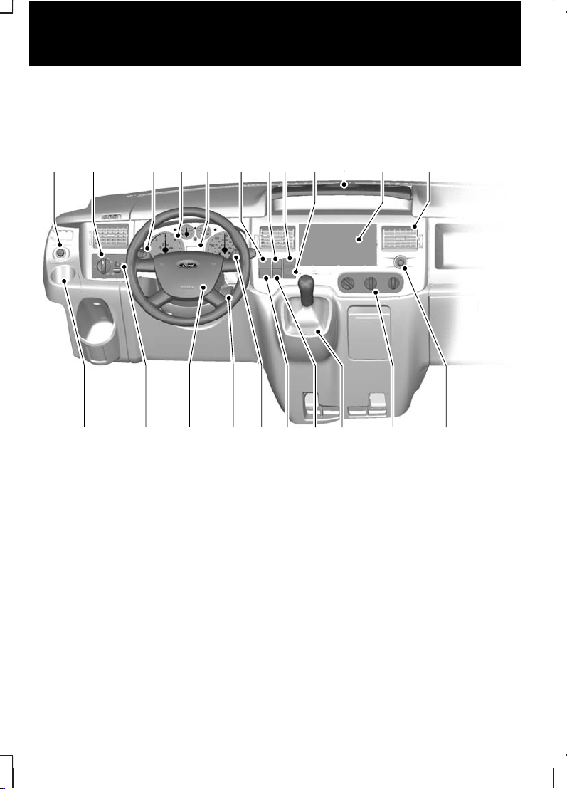
QUICK START
Instrument panel overview - left-hand drive
E70781
A B C D
TUV RS
E GF H J L
MNOQ P
KI
6
Quick start
Page 9
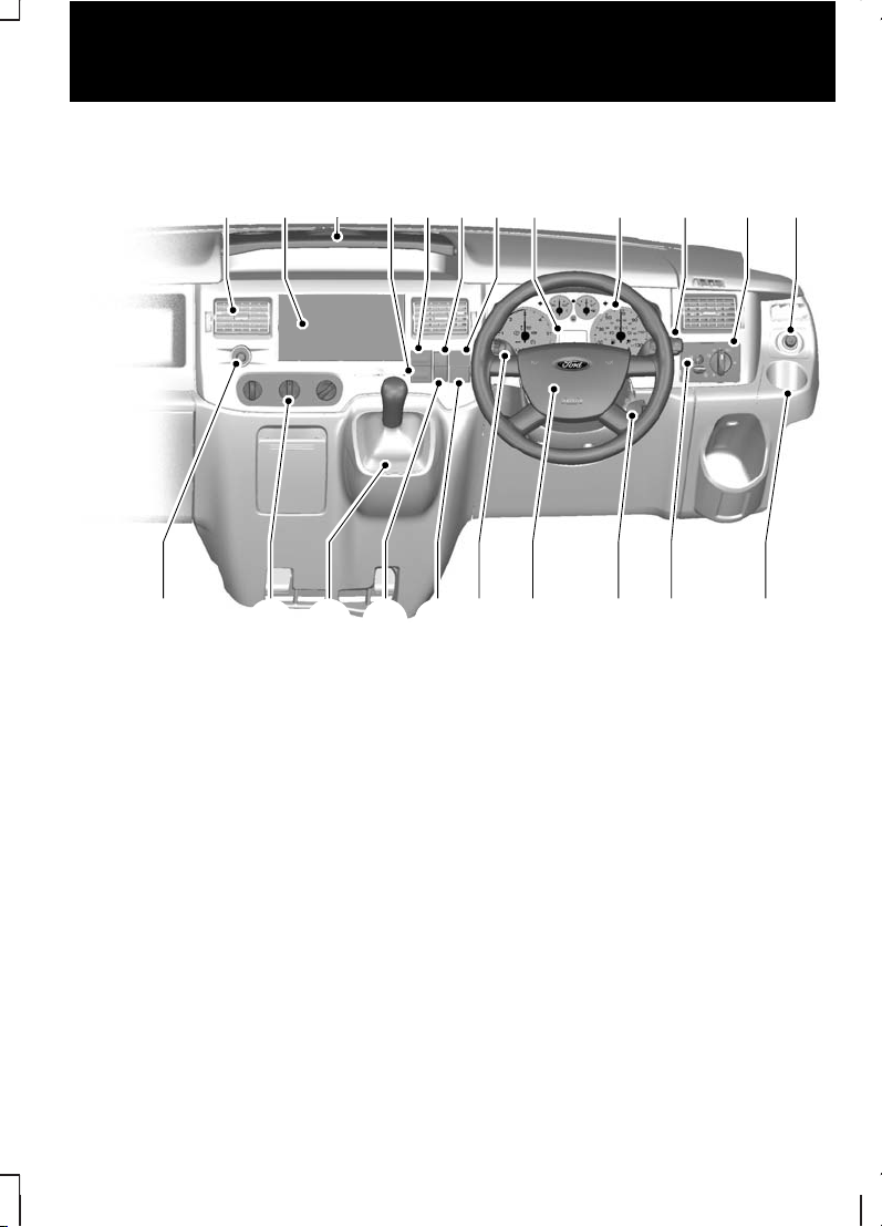
Instrument panel overview - right-hand drive
L E RDG F B
STQP CONM VU
A
E76166
JK I H
Electric exterior mirror switch. See Electric exterior mirrors
(page 47).
A
Lighting control. See Lighting control (page 32).
B
Multifunction lever. See Direction indicators (page 34). See
Lighting control (page 32).
C
Instrument cluster. See Gauges (page 49).
D
Clock.E
All wheel drive (AWD) indicator. See All-wheel drive (AWD) (page
92).
F
Hazard warning flasher switch. See Hazard warning flashers
(page 34).
G
Heated windscreen switch. See Heated windows and mirrors
(page 69).
H
7
Quick start
Page 10

Heated rear window switch. See Heated windows and mirrors
(page 69).
I
Tray with cup holders. See Cup holders (page 81).
J
Audio unit. See separate handbook.K
Air vents. See Air vents (page 66).
L
Cigar lighter. See Cigar lighter (page 80).
M
Climate controls. See Climate control (page 65).
N
Gear lever. See Manual transmission (page 92).
O
Passenger airbag deactivation warning lamp. See Disabling the
passenger airbag (page 17).
P
Stability control (ESP) switch. See Stability control (page 96).
Q
Wiper lever. See Wipers and washers (page 28).
R
Ignition switch.S
Horn.T
Headlamp levelling control. See Headlamp levelling (page 34).
U
Cup holder. See Cup holders (page 81).
V
8
Quick start
Page 11
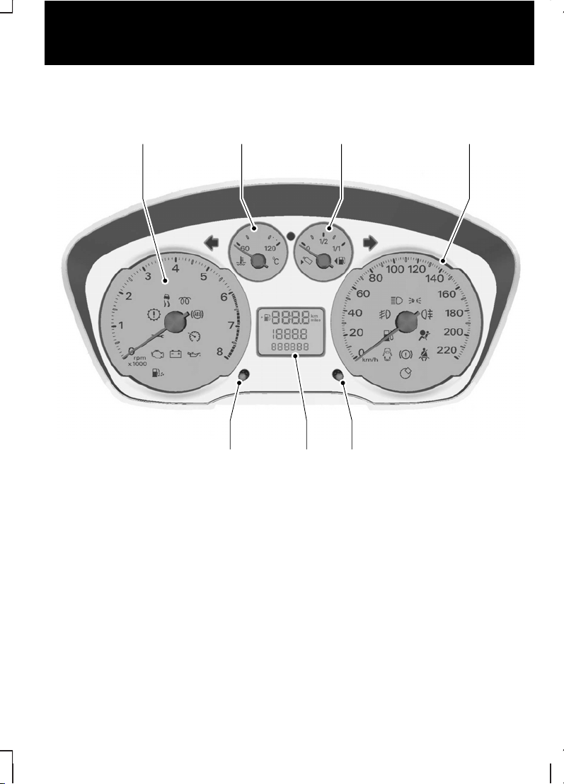
Low series instrument cluster
E71334
BA C
EG F
D
TachometerA
Engine coolant temperature gaugeB
Fuel gaugeC
SpeedometerD
Tripmeter reset buttonE
Odometer, tripmeter, clock, distance to empty and door open warning
indicator
F
Clock set buttonG
9
Quick start
Page 12
See Gauges (page 49).
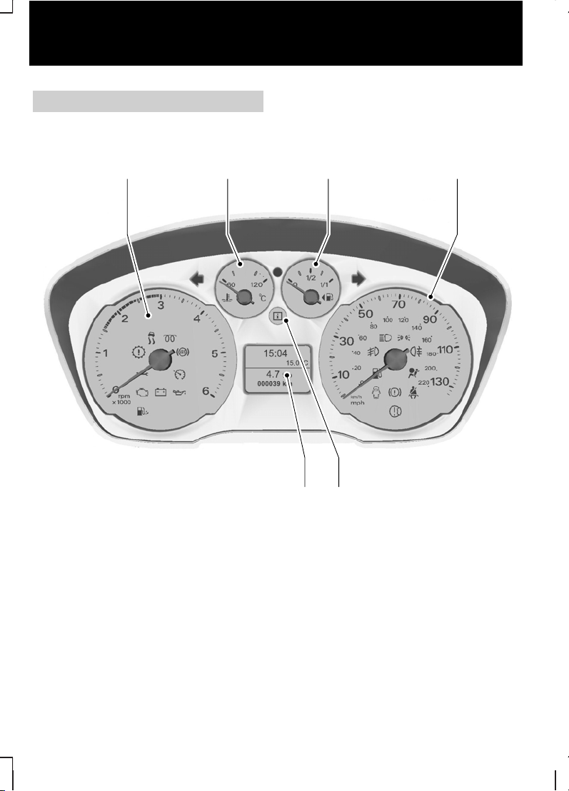
High series instrument cluster
E73043
BA C
EF
D
TachometerA
Engine coolant temperature gaugeB
Fuel gaugeC
SpeedometerD
Information message warning lampE
Information display. See Information displays (page 57).
F
10
Quick start
Page 13
See Gauges (page 49).
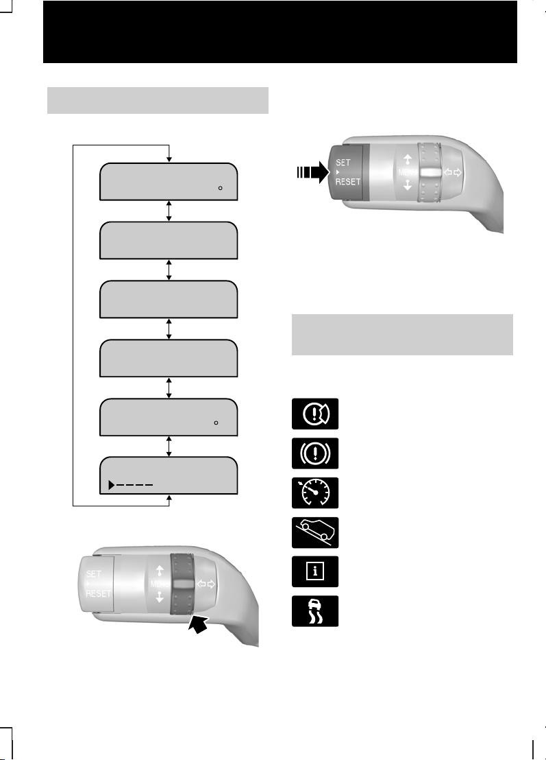
Information displays
15:04
15.0 C
DISTANCE TO
AVERAGE FUEL
8.0 l/100
AVERAGE SPEED
87 km/h
YOUR SETTINGS
SET/RESET
OUTSIDE AIR
TEMP 15.0 C
200 kmEMPTY:
E73982
E73265
Use the rotary control to scroll
through the menu.
E73266
Press the SET and RESET button
to select a sub-menu or the item that
you want to adjust.
See Information displays (page
57).
Warning lamps and
indicators
Brake pad wear warning
lamp
Brake system warning lamp
E71340
Cruise control indicator
E95339
Hill launch assist indicator
Message indicator lamp
Stability control (ESP) and
traction control warning
lamp
11
Quick start
Page 14
Service interval indicator
lamp (vehicles with a diesel
engine)
Shift indicator
Water-in-fuel indicator lamp
(vehicles with a diesel
engine)
See Warning lamps and
indicators (page 52).
Locking and unlocking
Rear doors
E71287
C
A
B
Unlock or openA
LockB
White visible, door lockedC
Sliding door
E71289
D
A B
CC
Van and KombiA
BusB
LockC
UnlockD
Double rear doors
E71290
A
B
OutsideA
InsideB
12
Quick start
Page 15
Tailgate
E71292
A
B
OutsideA
InsideB
Locking system operation
The locking system of your vehicle
may have been configured to
operate in one of three main lock
operation combinations. See
Locking and unlocking (page
20).
Auxiliary power sockets
E69125
CAUTION
If you use the auxiliary power
socket when the engine is not
running, the battery may discharge.
Switch the ignition on to use the
auxiliary power socket.
Engine idle speed after
starting
The engine may idle at a higher
speed than normal immediately after
starting from cold.
See Starting the engine (page
84).
13
Quick start
Page 16
PRINCIPLE OF OPERATION
Airbags
WARNINGS
Do not modify the front of your
vehicle in any way. This could
adversely affect deployment of the
airbags.
Original text according to ECE
R94.01: Extreme Hazard! Do not
use a rearward facing child restraint
on a seat protected by an air bag in
front of it!
Wear a seat belt and keep
sufficient distance between
yourself and the steering wheel. Only
when you use the seat belt properly,
can it hold you in a position that
allows the airbag to achieve its
optimum effect. See Sitting in the
correct position (page 74).
Have repairs to the steering
wheel, steering column, seats,
airbags and seat belts carried out by
properly trained technicians.
Keep the areas in front of the
airbags free from obstruction.
Do not affix anything to or over the
airbag covers.
Do not poke sharp objects into
areas where airbags are fitted.
This could damage and adversely
affect deployment of the airbags.
Use seat covers designed for
seats with side airbags. Have
these fitted by properly trained
technicians.
Note:
You will hear a loud bang and
see a cloud of harmless powdery
residue if an airbag deploys. This is
normal.
Note:
The front passenger airbag
protects both positions of a double
seat.
Note:
Only wipe airbag covers with
a damp cloth.
Driver and front passenger
airbags
E68581
30
o
30
o
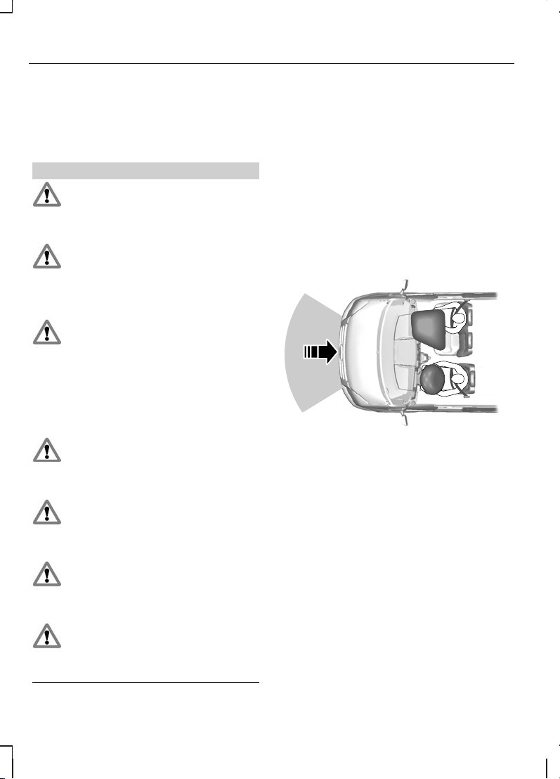
The driver and front passenger
airbags will deploy during significant
frontal collisions or collisions that are
up to 30 degrees from the left or the
right. The airbags will inflate within a
few thousandths of a second and
deflate on contact with the
occupants, thus cushioning forward
body movement. During minor frontal
collisions, overturns, rear collisions
and side collisions, the driver and
front passenger airbags will not
deploy.
14
Occupant protection
Page 17

Side airbags
E68905
Side airbags are fitted inside the
seatback of the front seats. A label
indicates that side airbags are fitted
to your vehicle.
The side airbags will deploy during
significant lateral collisions. Only the
airbag on the side affected by the
collision will deploy. The airbags will
inflate within a few thousandths of a
second and deflate on contact with
the occupants, thus providing
protection for the head and rib areas.
During minor lateral collisions,
overturns, front collisions and rear
collisions, the side airbags will not
deploy.
Seat belts
WARNINGS
Wear a seat belt and keep
sufficient distance between
yourself and the steering wheel. Only
when you use the seat belt properly,
can it hold you in a position to
achieve its optimum effect. See
Sitting in the correct position
(page 74).
Use a seat belt for only one
person.
Use the correct buckle for each
seat belt.
Do not use a seat belt that is
slack or twisted.
Do not wear thick clothing. The
seat belt must fit tightly around
your body to achieve its optimum
effect.
Position the shoulder strap of
the seat belt over the centre of
your shoulder and position the lap
strap tightly across your hips.
Seat belt pretensioners have a lower
deployment threshold than the
airbags. During minor collisions, it is
possible that only the seat belt
pretensioner will deploy.
15
Occupant protection
Page 18

FASTENING THE SEAT BELTS
E68584
E68585
E68586
WARNING
Insert the tongue into the buckle
until you hear a distinct click.
You have not fastened the seat belt
properly if you do not hear a click.
Pull the seat belt out steadily. It may
lock if you pull it sharply or if the
vehicle is on a slope.
Press the red button on the buckle
to release the seat belt. Let it retract
completely and smoothly.
16
Occupant protection
Page 19

SEAT BELT HEIGHT ADJUSTMENT
Front seat belt
E68901
Rear seat belt
E73074
WARNING
Make sure that the seat belt
runs smoothly through the
guide.
USING SEAT BELTS DURING PREGNANCY
E68587
WARNING
Position the seat belt correctly
for your safety and that of your
unborn child. Do not use only the lap
strap or the shoulder strap.
Position the lap strap comfortably
across your hips and low beneath
your pregnant abdomen. Position the
shoulder strap between your breasts,
above and to the side of your
pregnant abdomen.
DISABLING THE PASSENGER AIRBAG
WARNING
To avoid the risk of death or
serious injury, NEVER use a
rearward facing child restraint in the
front, unless the airbag is OFF.
17
Occupant protection
Page 20
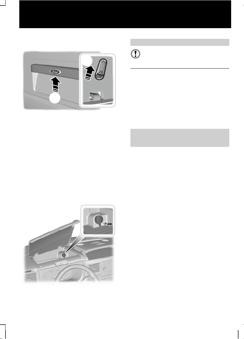
E71313
The key switch and the airbag
deactivation lamp are located in the
instrument panel.
If the airbag warning lamp in the
instrument cluster illuminates
intermittently, it means that there is
a malfunction. Remove the child
restraint from the front. Have the
system checked by a suitably trained
technician for your own safety. See
Warning lamps and indicators
(page 52).
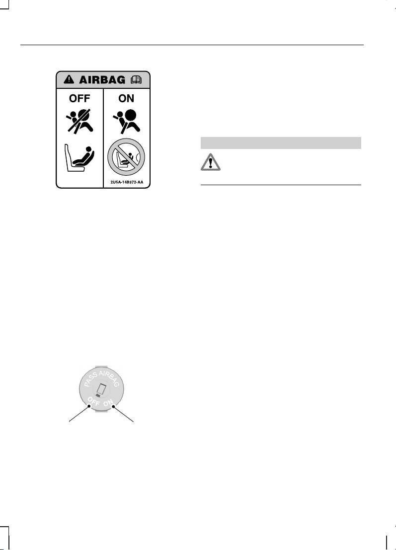
Disabling the passenger
airbag
A B
E71312
To use a child restraint in the front,
make sure that the key switch is
turned to position A.
When you switch the ignition on,
check that the passenger airbag
deactivation warning lamp comes on.
See Quick start (page 6).
Enabling the passenger
airbag
WARNING
For the adult restraint system to
perform as intended, make sure
that the airbag is ON.
After removing the child restraint
from the front, make sure that you
turn the key switch to position B.
18
Occupant protection
Page 21

GENERAL INFORMATION ON RADIO FREQUENCIES
CAUTION
The radio frequency used by
your remote control can also be
used by other short distance radio
transmissions (e.g. amateur radios,
medical equipment, wireless
headphones, remote controls and
alarm systems). If the frequencies are
jammed, you will not be able to use
your remote control. You can lock
and unlock the doors with the key.
Note:
You could unlock the doors if
you press the buttons on the remote
control unintentionally.
The operating range between your
remote control and your vehicle
varies depending on the
environment.
PROGRAMMING THE REMOTE CONTROL
You can programme a maximum of
eight remote controls to use with
your vehicle (including any supplied
with your vehicle). Ask your dealer for
instructions.
19
Keys and remote controls
Page 22
LOCKING AND UNLOCKING
Double locking
WARNING
Do not activate double locking
when persons or animals are
inside the vehicle. You will not be able
to unlock the doors from the inside if
you have double locked them.
Double locking is a theft protection
feature that prevents someone from
opening the doors from the inside.
You can only double lock the doors
if they are all closed. If you try to
double lock the doors when a door
is still open, you may hear a short
tone from the horn and the locks will
cycle. The door locks will return to
their previous state.
If you have double locked the doors
successfully, the direction indicators
will flash twice. If the hazard warning
flashers are on, the direction
indicators will give two long flashes.
Locking and unlocking the
doors with the key
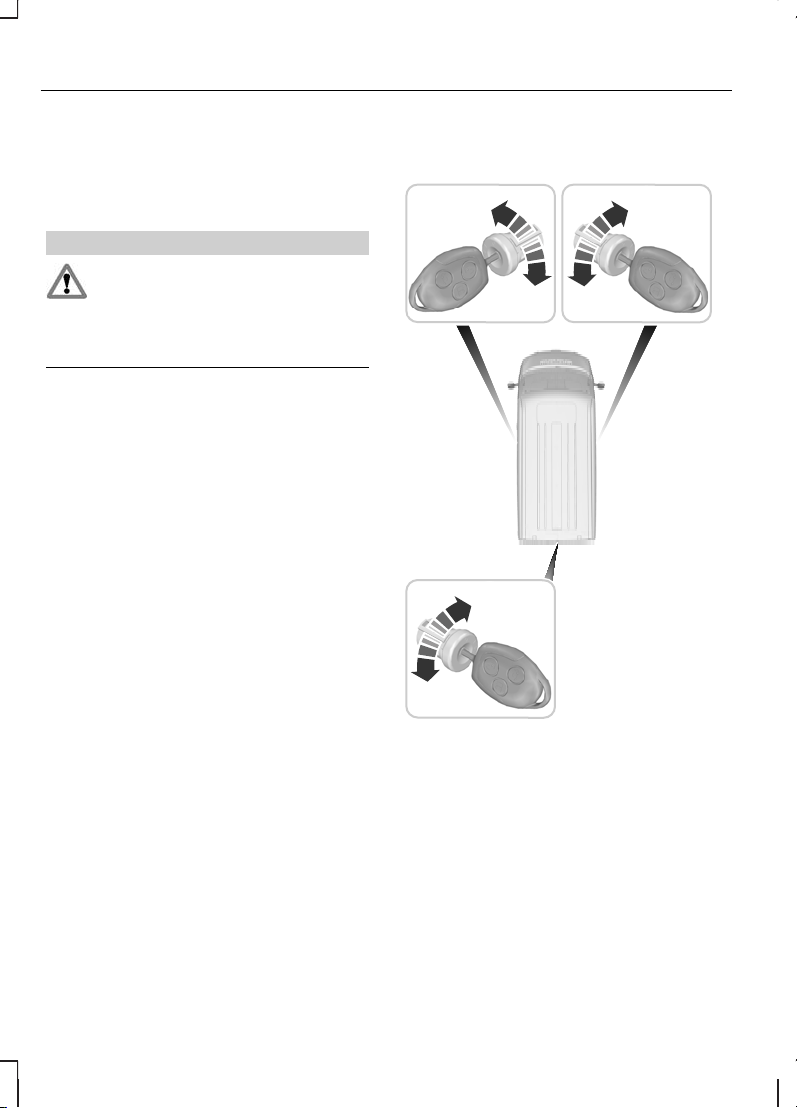
E71294
A
B
A
B
A
B
UnlockA
LockB
Double locking the doors with
the key
Turn the key to the unlock position
and then to the lock position to
double lock the doors.
20
Locks
Page 23
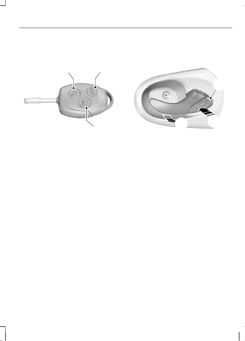
Locking and unlocking the
doors with the remote
control
E71293
A
CB
LockA
UnlockB
Cargo unlockC
Press the appropriate button once.
Double locking the doors with
the remote control
Press the lock button twice.
Locking and unlocking the
doors with the handles
Front doors
E71286
B
C
A
White markA
LockB
UnlockC
If you see the white mark, the door
is locked.
21
Locks
Page 24
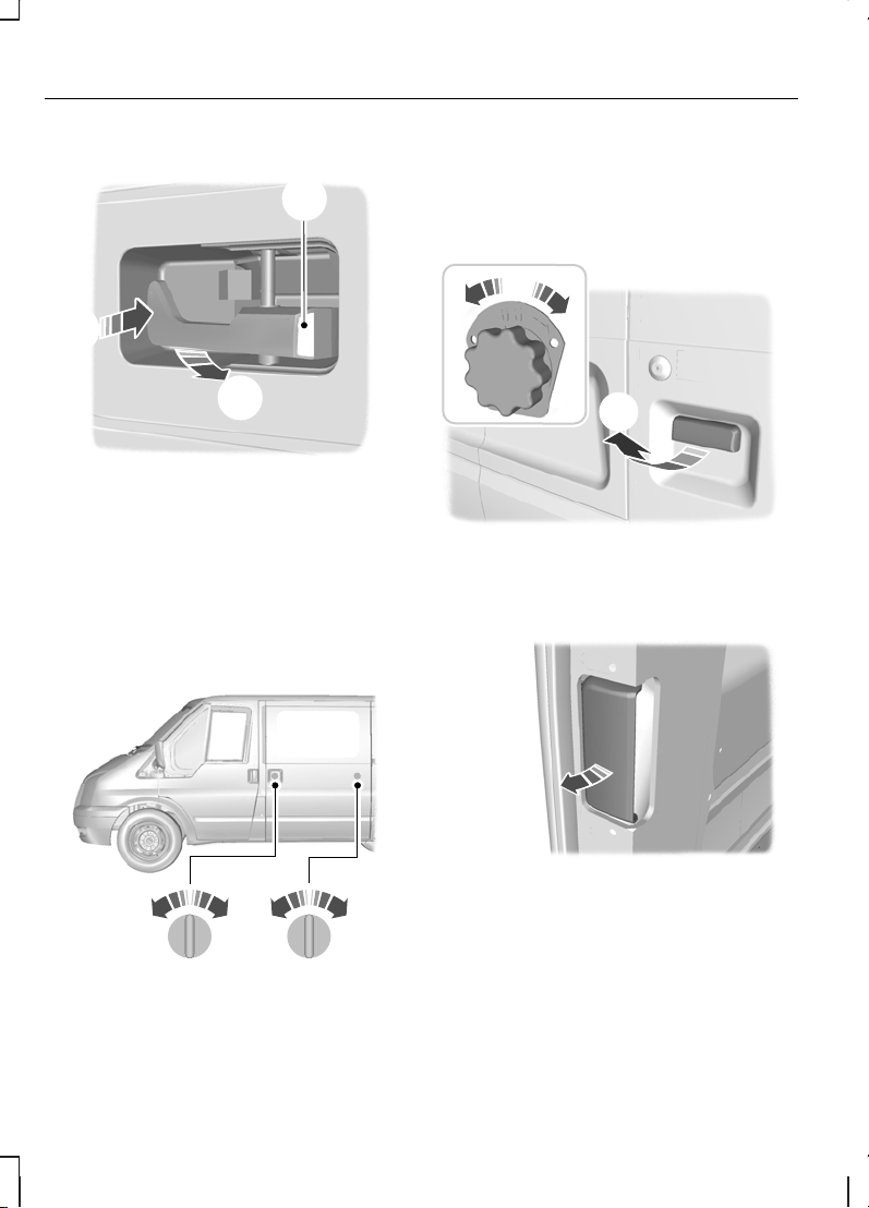
Rear doors
E71287
C
A
B
Unlock or openA
LockB
White markC
If you see the white mark, the door
is locked.
Sliding door
E71289
D
A B
CC
Van and KombiA
BusB
LockC
UnlockD
Double rear doors
E71290
A
B
OutsideA
InsideB
E71291
22
Locks
Page 25
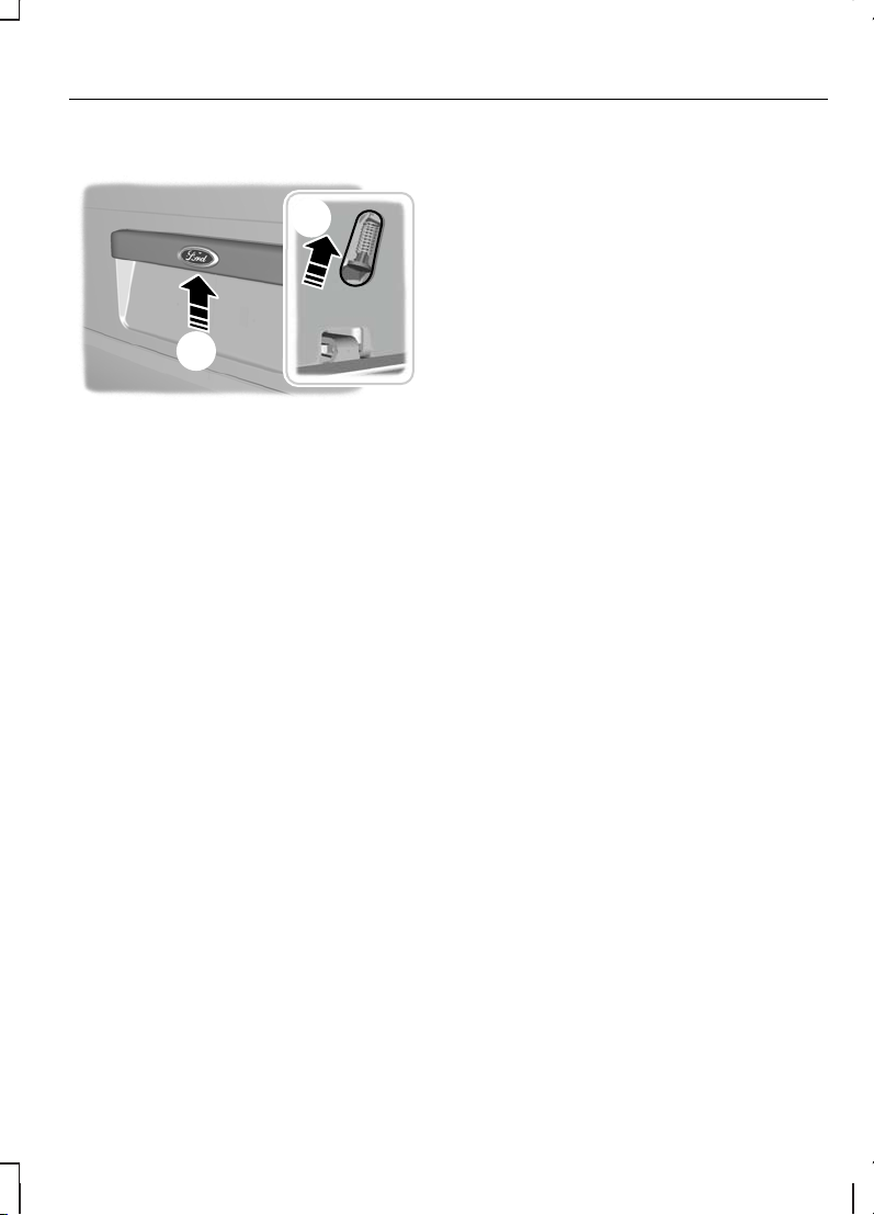
Tailgate
E71292
A
B
OutsideA
InsideB
Access the release button through
the aperture at the bottom of the
tailgate.
Slam locking
Note:
Do not leave your keys in the
vehicle.
Note:
You may hear a short tone
from the horn if you try to lock the
doors when a door is still open.
Slam locking allows you to lock a
door with the key or remote control
with the door open. The door will be
locked when it is closed.
Automatic locking
The doors will lock automatically
when you exceed 8 km/h (5 mph).
Unlock the doors with the interior
handle.
Automatic re-locking
The doors will re-lock automatically
if you do not open a door within 45
seconds of unlocking the doors with
the remote control. The door locks
and the alarm will return to their
previous state.
One-stage unlocking
Note:
The direction indicators will
flash once when you unlock the
doors.
When enabled, the following features
are available:
You will unlock all of the doors when
you:
•
pull either interior handle (except
if you have double locked the
doors).
•
turn the key in either of the door
locks.
•
press the unlock button on the
remote control once.
•
press the cargo unlock button on
the remote control once (Chassis
Cab).
You will unlock the rear doors or
tailgate and the sliding door if you
press the cargo unlock button once.
Two-stage unlocking
Note:
The direction indicators will
flash once when you unlock the
doors.
23
Locks
Page 26

You will unlock the front doors when
you:
•
pull either interior handle (except
if you have double locked the
doors).
•
turn the key in either of the door
locks.
•
press the unlock button on the
remote control once (Van, Bus
and Kombi).
You will unlock the driver side door
when you:
•
press the unlock button on the
remote control once (Chassis
Cab).
You will unlock the front doors, rear
doors and loadspace doors when
you:
•
turn the key in either of the front
door locks twice within three
seconds.
•
press the unlock button on the
remote control twice within three
seconds.
On Van vehicles, you will unlock the
rear doors or tailgate and the sliding
door if you press the cargo unlock
button once.
On Chassis Cab vehicles, you will
unlock the passenger side door if you
press the cargo unlock button once.
Zone re-locking
The locks on Van, Bus and Kombi are
split into two zones, cabin and cargo.
Chassis Cab has only the cabin zone.
•
Exit the vehicle and press the lock
button.
•
Press the unlock button or the
cargo unlock button once to open
the respective zone.
If you now open a door within the
unlocked zone, the other doors in
that zone will automatically lock.
Configurable unlocking
Configurable unlocking is set at the
time of vehicle purchase and allows
you to select which doors unlock
when the unlock and cargo unlock
buttons on the remote control are
pressed once or twice. If you have
this feature deactivated, it can not be
reactivated. Ask your dealer for
further information.
24
Locks
Page 27

PRINCIPLE OF OPERATION
The engine immobiliser is a theft
protection system that prevents
someone from starting the engine
with an incorrectly coded key.
CODED KEYS
Note:
Do not shield your keys with
metal objects. This may prevent the
receiver from recognising your key
as a valid one.
Note:
Have all of your remaining
keys erased and recoded if you lose
a key. Ask your dealer for further
information. Have replacement keys
recoded together with your existing
keys.
If you lose a key, you can obtain a
replacement from your Ford Dealer.
If possible, provide them with the key
number from the tag provided with
the original keys. You can also obtain
additional keys from your Ford
Dealer.
ARMING THE ENGINE IMMOBILISER
The engine immobiliser is armed
automatically a short time after you
have switched the ignition off.
The indicator in the instrument cluster
will flash to confirm that the system
is operating.
DISARMING THE ENGINE IMMOBILISER
The engine immobiliser is disarmed
automatically when you switch the
ignition on with a correctly coded key.
The indicator in the instrument cluster
will come on for approximately three
seconds and then go out. If the
indicator stays on for one minute or
flashes for approximately one minute
and then repeatedly at irregular
intervals, your key has not been
recognised. Remove the key and try
again.
If you attempt to start the engine with
an incorrectly coded key, you will
need to wait for approximately 20
seconds before attempting to start
the engine again with a correctly
coded key.
If you are unable to start the engine
with a correctly coded key, this
indicates a malfunction. Have the
immobiliser checked immediately.
25
Engine immobiliser
Page 28
PRINCIPLE OF OPERATION
All vehicles
If the alarm is triggered, the alarm
horns will sound for 30 seconds and
the hazard warning flashers will flash
for five minutes. If the cause of the
alarm being triggered has been
removed, the alarm will return to its
previous armed state. If the cause
has not been removed, the alarm
horns will sound again.
Vehicles with a perimeter
alarm
The perimeter alarm is a deterrent
against unauthorised access to your
vehicle through the doors and the
bonnet. It also protects the audio unit
and the trailer (if a Ford trailer-tow kit
is fitted). You can fully arm or partially
arm the alarm. Trailer detection is
disabled when you have partially
armed the alarm.
The perimeter alarm will be triggered
if someone:
•
opens a door.
•
opens the bonnet.
•
attempts to start the engine with
an incorrectly coded key.
•
removes the audio unit.
•
disconnects the trailer electrical
connector (if it was connected at
the time the alarm was armed).
Vehicles with a category
one alarm
E71401
The category one alarm is additional
to the perimeter alarm. Ultrasonic
interior motion detection protects
your vehicle against unauthorised
access to the passenger
compartment and the cargo area.
You can fully arm or partially arm the
alarm. Trailer detection and interior
motion detection are disabled when
you have partially armed the alarm.
Interior motion detection is not
activated if you arm the alarm when
a door is open.
The category one alarm will only
function correctly if all windows are
fully closed. Keep the area in front of
the motion sensors free from
obstruction.
The category one alarm is triggered
if:
•
motion is detected in the
passenger compartment or cargo
area.
•
someone attempts to access the
cargo area through the rear door
or tailgate window.
26
Alarm
Page 29

ARMING THE ALARM
Perimeter alarm
The alarm is armed 20 seconds after
you have locked the doors. This delay
allows you to close any doors or the
bonnet without triggering the alarm.
Partial arming
Lock the doors with the key. See
Locking and unlocking (page
20).
Full arming
Lock the doors with the remote
control or double lock the doors with
the key or the remote control. See
Locking and unlocking (page
20).
Category one alarm
Partial arming
Lock the doors with the key. See
Locking and unlocking (page
20).
Full arming
Note:
Do not fully arm the alarm if
someone is inside the vehicle.
Lock the doors with the remote
control or double lock the doors with
the key or the remote control. See
Locking and unlocking (page
20).
DISARMING THE ALARM
Perimeter alarm
Disarm and silence the alarm by
unlocking the doors with the key,
switching the ignition on with a
correctly coded key or unlocking the
doors with the remote control. See
Locking and unlocking (page
20).
Category one alarm
Disarm and silence the alarm by
unlocking the doors with the key in
the driver’s door and switching the
ignition on with a correctly coded key
within 12 seconds or unlocking the
doors with the remote control. See
Locking and unlocking (page
20).
27
Alarm
Page 30
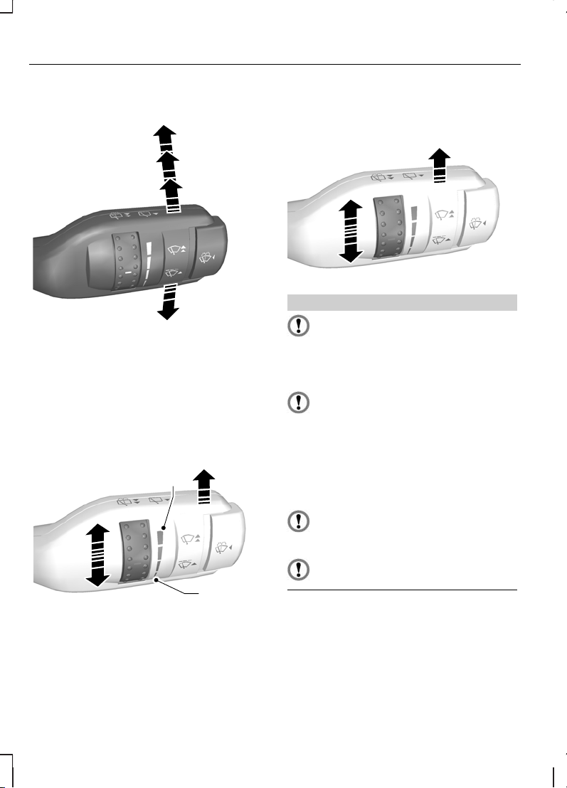
WINDSCREEN WIPERS
E71012
A
B
C
D
Single wipeA
Intermittent wipeB
Normal wipeC
High speed wipeD
Intermittent wipe
E71013
B
C
A
Long wipe intervalA
Intermittent wipeB
Short wipe intervalC
AUTOWIPERS
Autowipers
E71014
B
CAUTIONS
Do not switch autowipers on in
dry weather conditions. The rain
sensor is very sensitive and the
wipers may operate if dirt, mist or flies
hit the windscreen.
Replace the wiper blades as
soon as they begin to leave
bands of water and smears. If you do
not replace them, the rain sensor will
continue to detect water on the
windscreen and the wipers will
operate, even though the majority of
the windscreen is dry.
Fully defrost the windscreen in
icy conditions before you switch
autowipers on.
Switch autowipers off before you
enter a car wash.
28
Wipers and washers
Page 31

If you switch autowipers on after you
have switched the ignition on, the
wipers will cycle once regardless of
whether the windscreen is wet or dry.
The rain sensor will then continuously
measure the amount of water on the
windscreen and adjust the speed of
the wipers automatically.
If you switch the ignition on with
autowipers already switched on, the
wipers will not cycle until the rain
sensor detects water on the
windscreen.
E71015
B
A
Low sensitivityA
High sensitivityB
Adjust the sensitivity of the rain
sensor using the rotary control. If you
set the control to low sensitivity, the
wipers will operate when the sensor
detects a lot of water on the
windscreen. If you set the control to
high sensitivity, the wipers will
operate if the sensor detects a small
amount of water on the windscreen.
WINDSCREEN WASHERS
E71016
WARNING
Do not operate the windscreen
washers for more than 10
seconds or when the reservoir is
empty.
REAR WINDOW WIPER AND WASHERS
Intermittent wipe
E71017
The rear window wiper will follow the
windscreen wiper interval.
29
Wipers and washers
Page 32

Reverse gear wipe
The rear window wiper will operate
automatically when you select
reverse gear if the wiper lever is in
position A, B, C or D.
Rear window washer
E71018
WARNING
Do not operate the rear window
washer for more than 10
seconds or when the reservoir is
empty.
CHECKING THE WIPER BLADES
E66644
Run the tip of your fingers over the
edge of the blade to check for
roughness.
Clean the wiper blade lips with water
applied with a soft sponge.
CHANGING THE WIPER BLADES
E93783
1
2
E93784
3
30
Wipers and washers
Page 33

5
4
E93785
6
E93786
Install in the reverse order.
31
Wipers and washers
Page 34

LIGHTING CONTROL
Lighting control positions
E71094
D
B CAF
E
OffA
Side and tail lampsB
HeadlampsC
Front fog lampsD
Rear fog lampsE
Parking lampsF
Parking lamps
First, switch off the ignition.
Both sides
Push the lighting control inwards and
turn it to position F.
Single side
E77368
A
B
Right-hand sideA
Left-hand sideB
Main and dipped beam
E71095
Pull the lever fully towards the
steering wheel to switch between
main and dipped beam.
Headlamp flasher
Pull the lever slightly towards the
steering wheel.
32
Lighting
Page 35

Home safe lighting
Switch the ignition off and pull the
direction indicator lever towards the
steering wheel to switch the
headlamps on. You will hear a short
tone. The headlamps will go off
automatically after 3 minutes with any
door open, or 30 seconds after the
last door has been closed.
With all doors closed, but within the
30 second delay, opening any door
will result in the 3 minute timer
starting again.
The home safe lights can be
cancelled by either pulling the
direction indicator lever towards the
steering wheel again or by turning
the ignition switch ON.
AUTOLAMPS
E73840
A
Note:
If you have switched
autolamps on, you can only switch
the main beam on when autolamps
has switched the headlamps on.
The headlamps will come on and go
off automatically depending on the
ambient light.
FRONT FOG LAMPS
E71096
WARNING
Only use the front fog lamps
when visibility is considerably
restricted by fog, snow or rain.
Note:
You cannot switch the front
fog lamps on if you have switched
autolamps on.
REAR FOG LAMPS
E71097
33
Lighting
Page 36

WARNING
Do not use the rear fog lamps
when it is raining or snowing and
visibility is more than 50 metres.
Note:
You cannot switch the rear
fog lamps on if you have switched
autolamps on.
HEADLAMP LEVELLING
You can adjust the level of the
headlamp beams according to the
vehicle load.
E74611
A
B
Raise beamsA
Lower beamsB
Set the headlamp levelling control to
zero when your vehicle is unloaded.
Set it to provide illumination between
35 and 100 metres when your vehicle
is partially or fully loaded.
HAZARD WARNING FLASHERS
E71943
For item location: See Quick start
(page 6).
DIRECTION INDICATORS
E71098
Note:
Tap the lever up or down to
make the direction indicators flash
only three times.
34
Lighting
Page 37

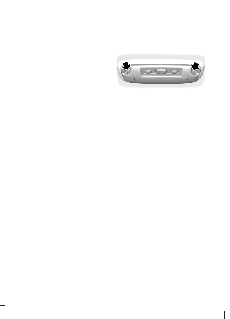
INTERIOR LAMPS
Courtesy lamps - Vehicles
without interior sensors
E71099
B
C
A
OnA
OffB
Door contactC
Courtesy lamps that are not fitted
with a switch will only come on when
the switch on the front courtesy lamp
is set to position C and you open a
door.
Vehicles with double
locking
If you set the switch to position C, the
courtesy lamps will stay on for a short
time after you close the doors. They
will go off immediately when you
switch the ignition on.
When you switch the ignition off, the
courtesy lamps will come on. They
will go off automatically after a short
time.
If you leave a door open, the
courtesy lamps will go off
automatically after 30 minutes. To
switch them back on, switch the
ignition on for a short time.
Courtesy lamp - Vehicles
with interior sensors
C
B
A
E71945
OffA
Door contactB
OnC
If you set the switch to position B, the
courtesy lamp will come on when you
unlock or open a door or the tailgate.
If you leave a door open, it will go off
automatically after a short time to
prevent the vehicle battery from
discharging. To switch it back on,
switch the ignition on for a short time.
The courtesy lamp will also come on
when you switch the ignition off. It will
go off automatically after a short time
or when you start or restart the
engine.
If you set the switch to position C, the
courtesy lamp will come on. It will go
off automatically after a short time to
prevent the vehicle battery from
discharging. To switch it back on,
switch the ignition on for a short time.
35
Lighting
Page 38

Reading lamps
E71946
If you switch the ignition off, the
reading lamps will go off automatically
after a short time to prevent the
vehicle battery from discharging. To
switch them back on, switch the
ignition on for a short time.
STEPWELL LAMPS
The stepwell lamps will come on and
go off automatically when you open
and close the doors. If you unlock the
doors with the remote control, they
will come on. They will go off
automatically after a short time.
CHANGING A BULB
WARNINGS
Switch the lights and the ignition
off.
Let the bulb cool down before
removing it.
CAUTIONS
Do not touch the glass of the
bulb.
CAUTIONS
Only fit bulbs of the correct
specification. See Bulb
specification chart (page 44).
Note:
We recommended that you
ask your dealer to change the bulbs
if your vehicle is fitted with air
conditioning. Some bulbs are difficult
to access.
Note:
You will need to remove the
headlamp to change the headlamp,
side lamp or front direction indicator
bulbs.
Note:
The following instructions
describe how to remove the bulbs.
Fit replacements in the reverse order
unless otherwise stated.
Removing a headlamp
E71057
2
4
3
1. Open the bonnet. See
Maintenance (page 129).
2. Remove the screws.
36
Lighting
Page 39

3. Disconnect the electrical
connector.
4. Remove the headlamp.
Headlamp main and dipped
beam
E71058
3
2
1
E71059
45
1. Remove the headlamp.
2. Release the clips.
3. Remove the cover.
4. Disconnect the electrical
connector.
5. Release the clip and remove the
bulb.
Side lamps
E71060
2341
1. Remove the headlamp.
2. Remove the cover.
3. Remove the bulb and the bulb
holder.
4. Remove the bulb.
Front direction indicators
E71061
3
2
1
37
Lighting
Page 40

1. Remove the headlamp.
2. Turn the bulb holder
anti-clockwise and remove it.
3. Gently press the bulb into the bulb
holder, turn it anti-clockwise and
remove it.
Front fog lamps
E71062
1
2
Note:
You cannot separate the bulb
from the bulb holder.
1. Disconnect the electrical
connector.
2. Turn the bulb holder
anti-clockwise and remove it.
Side repeaters
E71063
13
2
1. Carefully remove the side
repeater.
2. Hold the bulb holder, turn the
housing anti-clockwise and
remove it.
3. Remove the bulb.
E71064
1
2
1. Turn the lens clockwise and
remove it.
2. Gently press the bulb into the bulb
holder, turn it anti-clockwise and
remove it.
38
Lighting
Page 41

Side marker lamps
Chassis cab and Flatbed truck
with extended frame
E75022
1
2
3
1. Disconnect the electrical
connector.
2. Turn the bulb holder
anti-clockwise and remove it.
3. Remove the bulb.
Jumbo van
E71065
1
2
1. Turn the lens in either direction
and remove it.
2. Remove the bulb.
Rear lamps
Bus and Kombi
E71066
1 2
39
Lighting
Page 42

A
B
C
D
E71067
Tail and brake lampA
Direction indicatorB
Reversing lampC
Fog lampD
1. Remove the wing nuts.
2. Remove the rear lamp and unclip
the bulb holder.
3. Gently press the bulb into the bulb
holder, turn it anti-clockwise and
remove it.
Chassis cab and Flatbed truck
E71068
2
1
3
E71069
E D C B A
Direction indicatorA
Brake lampB
Tail lampC
Reversing lampD
Fog lampE
1. Release the retaining clip and
move the plastic frame to the
side.
2. Remove the lens.
3. Gently press the bulb into the bulb
holder, turn it anti-clockwise and
remove it.
40
Lighting
Page 43

Rear side lamps
Flatbed truck
E71072
2
1
1. Carefully prise the lens from the
holder.
2. Gently press the bulb into the bulb
holder, turn it anti-clockwise and
remove it.
Central brake lamp
E71071
1
2
3
1. Remove the screws.
2. Remove the lamp.
3. Remove the bulb.
Roof position lamps
E71073
1
2
3
1. Remove the screws.
2. Remove the lens.
3. Gently press the bulb into the bulb
holder, turn it anti-clockwise and
remove it.
Number plate lamp
Vehicles with double rear
doors
E71074
2
1
1. Remove the lens.
2. Remove the bulb.
41
Lighting
Page 44

Vehicles with a tailgate
E71075
2
2
1
1
1. Open the lens.
2. Gently press the bulb into the bulb
holder, turn it anti-clockwise and
remove it.
Flatbed truck
E71076
1
2
1. Remove the lens.
2. Gently press the bulb into the bulb
holder, turn it anti-clockwise and
remove it.
Front interior lamps
Vehicles without interior
sensors
E71077
1
2
1. Carefully prise out the lamp.
2. Gently press the bulb into the bulb
holder, turn it anti-clockwise and
remove it.
Vehicles with interior sensors
E73091
1
2
42
Lighting
Page 45

E73092
3
1. Carefully prise out the lamp.
2. Remove the lens.
3. Remove the bulb.
Rear interior lamps
E71078
1
2
1. Carefully prise out the lamp.
2. Remove the bulb.
Front reading lamps
E73938
1
2
E73939
3
1. Carefully prise out the lamp.
2. Turn the bulb holder
anti-clockwise and remove it.
3. Remove the bulb.
43
Lighting
Page 46

Stepwell lamps
2
2
E71080
1
3
1. Carefully prise out the lamp.
2. Remove the bulb holder.
3. Remove the bulb.
BULB SPECIFICATION CHART
Watts (Specification)Bulb
55/60Headlamp main and dipped beam
5Side lamp
21Front direction indicator
55 (H11)Front fog lamp
5Side repeater
21/5Side repeater
3Side marker lamp
21/5Tail and brake lamp
10Tail lamp - Chassis Cab and Flatbed Truck
21Brake lamp - Chassis Cab and Flatbed Truck
21Rear direction indicator
21Reversing lamp
21Rear fog lamp
44
Lighting
Page 47

Watts (Specification)Bulb
4Rear side lamp - Flatbed Truck
16Central brake lamp
4Roof marker lamp
5
Number plate lamp - Vehicles with double rear
doors
10
Number plate lamp - Except vehicles with double
rear doors
10Interior lamp
10Reading lamp
10Stepwell lamp
45
Lighting
Page 48

ELECTRIC WINDOWS
WARNING
Do not operate the electric
windows unless they are free
from obstruction.
E71327
Switch on the ignition to operate the
electric windows.
Opening the driver window
automatically
Press the switch to the second action
point and release it. Press it again to
stop the window.
EXTERIOR MIRRORS
E71273
A
Convex mirrorA
WARNING
Do not over estimate the
distance of the objects that you
see in the convex mirrors. Objects
seen in convex mirrors will appear
smaller and further away than they
actually are.
The mirrors increase your rearward
field of vision to reduce the so-called
blind spot at the rear quarter of your
vehicle.
46
Windows and mirrors
Page 49

E71274
Make sure that you fully engage the
mirror in its support when returning
it to its original position.
ELECTRIC EXTERIOR MIRRORS
E71280
B
C
A
Left-hand mirrorA
OffB
Right-hand mirrorC
E71281
The electric exterior mirrors are fitted
with a heating element that will
defrost or demist the mirror glass.
See Climate control (page 65).
INTERIOR MIRROR
E71272
Dip the mirror to reduce glare when
driving at night.
47
Windows and mirrors
Page 50

SLIDING WINDOWS
E66497
1
2
REAR QUARTER WINDOWS
E66498
Pull the lever outwards to open the
window. Press the lever in the middle
to engage it in its catch. Pull the lever
in the middle to close the window.
Push it backwards until it engages in
its catch.
48
Windows and mirrors
Page 51

GAUGES
Low series instrument cluster
E71334
BA C
EG F
D
TachometerA
Engine coolant temperature gaugeB
Fuel gaugeC
SpeedometerD
Tripmeter reset buttonE
49
Instruments
Page 52

Odometer, tripmeter, clock, distance to empty and door open warning
indicator
F
Clock set buttonG
High series instrument cluster
E73043
BA C
EF
D
TachometerA
Engine coolant temperature gaugeB
Fuel gaugeC
SpeedometerD
50
Instruments
Page 53

Message warning lampE
Message centre. See General information (page 57).
F
Engine coolant temperature
gauge
Shows the temperature of the engine
coolant. At normal operating
temperature, the needle will remain
in the centre section.
CAUTION
Do not restart the engine until the
cause of overheating has been
resolved.
If the needle moves towards 120°C,
the engine is overheating. Stop the
engine, switch the ignition off and
determine the cause once the
engine has cooled down. See
Engine coolant check (page 137).
See Reduced engine
performance (page 112).
Fuel gauge
The arrow adjacent to the fuel pump
symbol tells you on which side of
your vehicle the fuel filler cap is
located.
Odometer, tripmeter and
clock
Low series instrument cluster
A B
C
E71335
Clock and distance to emptyA
TripmeterB
OdometerC
The tripmeter will register the
distance of individual journeys. Press
the reset button to reset the
tripmeter.
51
Instruments
Page 54

WARNING LAMPS AND INDICATORS
Low series instrument
cluster
The following warning lamps and
indicators will come on briefly when
you switch the ignition on to confirm
that the system is operational:
•
ABS
•
Airbag
•
Brake pad wear
•
Brake system
•
Cruise control
•
Door open
•
Engine
•
Hill launch assist
•
Ignition
•
Low fuel level
•
Oil pressure
•
Engine
•
Service interval
•
Shift
•
Stability control (ESP) and traction
control
•
Water-in-fuel
High series instrument
cluster
The following warning lamps and
indicators will come on briefly when
you switch the ignition on to confirm
that the system is operational:
•
ABS
•
Airbag
•
Brake pad wear
•
Brake system
•
Cruise control
•
Engine
•
Hill launch assist
•
Ignition
•
Low fuel level
•
Message indicator
•
Shift
•
Stability control (ESP) and traction
control
•
Water-in-fuel
If a warning or indicator lamp does
not illuminate when the ignition is
switched on, this indicates a
malfunction. Have the system
checked by properly trained
technician.
ABS warning lamp
If it illuminates when driving,
this indicates a malfunction.
Have the system checked
by a properly trained technician. You
will continue to have normal braking
(without ABS) but have this checked
as soon as possible.
Airbag warning lamp
If it does not illuminate, if it
stays on or illuminates
intermittently or continuously
while driving, this indicates a
malfunction. Have the system
checked by a properly trained
technician.
52
Instruments
Page 55

Brake pad wear warning
lamp
It will illuminate when the
brake pads have worn down
to a predetermined limit.
Have this checked by a properly
trained technician as soon as
possible.
Brake system warning lamp
WARNING
Reduce your speed gradually.
Use your brakes with great care.
Do not step on the brake pedal
abruptly.
If it illuminates when you are
driving, this indicates a
malfunction in one of the
brake circuits. Check the brake fluid
level. See Brake and clutch fluid
check (page 137).
WARNING
Have this checked immediately.
If the brake system warning lamp
illuminates with the ABS warning
lamp, this indicates a malfunction.
Stop your vehicle as soon as it is safe
to do so and have this checked
before continuing you journey.
Cruise control indicator
E71340
It will illuminate when you
have set a speed using the
cruise control system. See
Using cruise control (page 106).
Direction indicator
Flashes during operation. A
sudden increase in the rate
of flashing warns of a failed
indicator bulb. See Changing a
bulb (page 36).
Door open warning lamp
It will illuminate when you
switch the ignition on if you
have not closed the doors,
the bonnet or tailgate properly.
Engine warning lamps
Malfunction indicator lamp
Powertrain warning lamp
All vehicles
If either lamp illuminates when the
engine is running, this indicates a
fault. The engine will continue to run
but it may have limited power. If it
flashes when you are driving,
reduce the speed of your
vehicle immediately. If it
continues to flash, avoid heavy
acceleration or deceleration. Have
the system checked by a properly
trained technician immediately.
53
Instruments
Page 56

WARNING
Have this checked immediately.
If both lamps illuminate together,
stop your vehicle as soon as
it is safe to do so (continued use
may cause reduced power and
cause the engine to stop). Turn the
ignition off and attempt to restart the
engine. If the engine restarts have
the system checked by a properly
trained technician immediately. If the
engine does not restart the vehicle
must be checked before continuing
your journey.
Front fog lamp indicator
It will illuminate when you
switch the front fog lamps
on.
Glow plug indicator
See Starting a diesel
engine (page 85).
Headlamp indicator
It will illuminate when you
switch the headlamp dipped
beam or the side and tail
lamps on.
Hill launch assist indicator
E95339
While driving, it illuminates
during activation of the
system. After switching on
the ignition, if it does not illuminate
this indicates that the system has
been disabled. Your dealer can
re-enable it. During a malfunction, the
system switches off and it will not
illuminate while driving.
Ignition warning lamp
All vehicles
If it illuminates when you are
driving, this indicates a
malfunction. Switch off all
unnecessary electrical equipment.
Have the system checked by a
properly trained technician
immediately.
Low fuel level warning lamp
If it illuminates, refuel as soon
as possible.
The arrow adjacent to the fuel pump
symbol tells you on which side of
your vehicle the fuel filler cap is
located.
Main beam indicator
It will illuminate when you
switch the headlamp main
beam on. It will flash when
you use the headlamp flasher.
54
Instruments
Page 57

Message indicator
It will illuminate when a new
message is stored in the
information display. See
Information messages (page
59).
Oil pressure warning lamp
CAUTION
Do not resume your journey if the
oil pressure warning lamp
illuminates despite the oil level being
correct. Have the system checked
by a properly trained technician
immediately.
If the lamp stays on after
starting or illuminates during
a journey, this indicates a
malfunction. Stop your vehicle as
soon as it is safe to do so and switch
the engine off. Check the engine oil
level. See Engine oil check (page
136).
Rear fog lamp indicator
It will illuminate when you
switch the rear fog lamps
on.
Service interval indicator
Vehicles with a diesel engine
It will illuminate when a
service is due or there is
excessive soot or sludge in
the oil. Have the engine oil changed
as soon as possible.
Your dealer will switch the service
interval indicator lamp off for you after
completing the service.
Shift indicator
It will illuminate for a short
period of time to inform you
that shifting to a higher gear
may give better fuel economy and
lower CO2 emissions. It will not
illuminate during periods of high
acceleration, braking or when the
clutch pedal is pressed.
Soot overload warning
lamp
E95449
It will illuminate when a
regeneration is due. See
Diesel particulate filter
(DPF) (page 85).
CAUTIONS
If it illuminates with the
malfunction indicator lamp, it
indicates an overload of soot. Have
this checked by a properly trained
technician as soon as possible.
If it illuminates with the powertrain
warning lamp, your diesel
particulate filter may need replacing.
Have this checked by a properly
trained technician immediately.
Stability control (ESP) and
traction control warning
lamp
Note:
If either the ESP system or
traction control system malfunctions,
the respective system will switch off
automatically.
55
Instruments
Page 58

It will flash when either
system is operating. If it
does not flash or it comes
on when you are driving, this
indicates a malfunction. Have the
system checked by a properly
trained technician immediately.
If you switch ESP off, the warning
lamp will come on. The lamp will go
out when you switch the system
back on or when you switch the
ignition off.
Water-in-fuel indicator
Vehicles with a diesel engine
It will illuminate if there is
excess water in the fuel filter.
Drain off the water
immediately. See Draining the
fuel filter water trap (page 138).
AUDIBLE WARNINGS AND INDICATORS
Door open warning
The door open warning chime will
sound if you switch the ignition on
and you have not closed the doors,
the bonnet or tailgate properly.
Message centre
See Personalised settings (page
62).
56
Instruments
Page 59

GENERAL INFORMATION
WARNING
For road safety reasons, set and
reset the functions only when
the vehicle is stationary.
Various functions can be
programmed using the message
centre and the multi-function lever
on the steering column.
The message centre also provides
warning messages about faults or
system malfunctions. See
Information messages (page
59).
Main menu
Overview of the main menu
displays
15:04
15.0 C
DISTANCE TO
AVERAGE FUEL
8.0 l/100
AVERAGE SPEED
87 km/h
YOUR SETTINGS
SET/RESET
OUTSIDE AIR
TEMP 15.0 C
200 kmEMPTY:
E73982
The various sub-menus are
accessed from the main menu.
57
Information displays
Page 60

Controls
E73265
Use the rotary control to scroll
through the menu.
E73266
Note:
If the chimes are activated, a
short tone will sound each time the
button is pressed.
Press the SET and RESET button
to select a sub-menu or the item that
you want to adjust.
Odometer
4.7 trip
15:04
000039 km
15.0 C
E73983
Tripmeter
4.7 trip
15:04
000039 km
15.0 C
E73984
Press the SET and RESET button
for at least 2 seconds to reset.
Distance to empty
E73985
4.7 trip
DISTANCE TO
EMPTY 200 km
000039 km
Note:
Changes in driving pattern
may cause the value to vary.
Indicates the approximate distance
the vehicle will travel on the fuel
remaining in the tank.
Average fuel consumption
E73986
4.7 trip
AVERAGE FUEL
8.0 l/100
000039 km
Indicates the average fuel
consumption since the function was
last reset.
58
Information displays
Page 61

Press the SET and RESET button
to reset.
Average speed
E73987
4.7 trip
AVERAGE SPEED
87 km/h
000039 km
Indicates the average speed
calculated over the last 1 000
kilometres (600 miles) or since the
function was last reset.
Press the SET and RESET button
to reset.
Outside air temperature
E73988
4.7 trip
OUTSIDE AIR
TEMP
000039 km
15.0 C
WARNING
Even if the temperature rises to
above +4 ºC there is no
guarantee that the road is free of
hazards caused by inclement
weather.
A warning chime will sound in the
following conditions:
•
+4 ºC or lower: frost warning
•
0 ºC or lower: danger of icy roads
INFORMATION MESSAGES
Warning messages
When certain warning message
appear in the display, you must press
the SET and RESET button to
acknowledge them.
E73273
Some warning messages are
supplemented by the message
centre warning lamp above the
display which comes on red or
amber, depending on the severity of
the problem.
If a warning message accompanied
by the warning lamp is present, the
warning lamp will remain on.
59
Information displays
Page 62

MeaningWarning
lamp
Messages
Malfunction of the engine or related
systems. Stop the vehicle as soon as safely
possible and switch off the engine immediately. Have the engine checked by properly
trained technicians.
redENGINE MALFUNC-
TION
Low oil level. Stop the vehicle as soon as
safely possible and switch off the engine
immediately. Top up the engine oil. See
Engine oil check (page 136).
redLOW OIL LEVEL
Water has been detected in the fuel. Have
the fuel system checked by properly trained
technicians.
redWATER DETECTED IN
FUEL
Outside temperature is below 0 ºCredLOW OUTSIDE
TEMPERATURE
Outside temperature is below +4 ºCamberLOW OUTSIDE
TEMPERATURE
Have your vehicle checked by properly
trained technicians.
amberSERVICE OIL NOW
Check all doors are fully closed.amberDOOR AJAR CLOSE
DOOR
The driver’s door is open.amberDRIVER DOOR OPEN
The front passenger’s door is open.amberPASSENGER DOOR
OPEN
The rear door on the driver’s side is open.amberDRIVER SIDE REAR
DOOR OPEN
The rear door on the passenger’s side is
open.
amberPASSENGER SIDE
REAR DOOR OPEN
The cargo compartment or rear door is
open.
amberLUGGAGE COMP
OPEN
The bonnet is open.amberBONNET OPEN
60
Information displays
Page 63

MeaningWarning
lamp
Messages
Indicates the oil service is due.-SERVICE OIL SOON xx
DAYS
Service oil reset is in progress.-SERVICE OIL RESET IN
PROG
Service oil reset is complete.-SERVICE OIL RESET
COMPLETE
Alarm clock is ringing. See Personalised
settings (page 62).
-*ALARM* RESET TO
STOP
61
Information displays
Page 64

PERSONALISED SETTINGS
Overview of the your
settings menu displays
E73990
YOUR SETTINGS
YOUR SETTINGS
EXIT
LANGUAGE
ENGLISH
MEASURE UNITS
METRIC
MESSAGE CHIMES
OFF
CLOCK SETTING
12:5931.12.04
12:5931.12.04
TIME FORMAT
24 h
ALARM SETTING
OFF
SET/RESET
Your settings menu
YOUR SETTINGS
SET/RESET
E73989
4.7 trip
000039 km
The following sub-menus are
available in the your settings
menu:
•
Language
•
Clock setting
•
Alarm setting
•
Time format
•
Units of measure
•
Message chimes
Language setting
LANGUAGE
ENGLISH
E73991
4.7 trip
000039 km
A choice of eleven languages are
available:
English (UK), German, Italian, French,
Spanish, Turkish, Russian, Dutch,
Polish, Swedish, Portuguese.
Once selected, turn the rotary control
to save the setting and exit the menu.
Clock setting
See Clock (page 79).
62
Information displays
Page 65

Alarm setting
ALARM SETTING
04.08.00 23.59
OFF
E74286
4.7 trip
000039 km
•
Press and hold SET and RESET.
The day starts to flash. Adjust
using the rotary control.
•
Press the SET and RESET
button to confirm the setting and
move to the month.
•
Proceed in the same way to set
the year, hours and minutes.
•
After setting the minutes and
pressing SET and RESET, the
time is stored.
•
Press SET and RESET to turn
the alarm on or off.
Alarm activated
E74287
4.7 trip
000039 km
15:04
15.0 C
E74387
4.7 trip
*ALARM*
RESET TO STOP
000039 km
Press SET and RESET to turn off.
Time format
TIME FORMAT
24 h
E73995
4.7 trip
000039 km
Press SET and RESET to toggle
between 12 and 24 hour format.
Units of measure
MEASURE UNITS
METRIC
E73993
4.7 trip
000039 km
Press SET and RESET to toggle
between metric and imperial units.
Message chimes
The following chimes can be
deactivated:
•
ambient temperature at 4°C
•
set time confirmation
•
SET and RESET button press
MESSAGE CHIMES
OFF
E73994
4.7 trip
000039 km
63
Information displays
Page 66

Press SET and RESET to toggle the
chimes on and off.
Your Settings – Exit
E73996
YOUR SETTINGS
EXIT
Press SET and RESET to exit.
64
Information displays
Page 67

PRINCIPLE OF OPERATION
Outside air
Keep the air intakes forward of the
windscreen free from obstruction
(snow, leaves etc.) to allow the
climate control system to function
effectively.
Recirculated air
CAUTION
Prolonged use of recirculated air
may cause the windows to mist
up. If the windows mist up, follow the
settings for defrosting and demisting
the windscreen.
The air currently in the passenger
compartment will be recirculated.
Outside air will not enter the vehicle.
Heating
Heating performance depends on
the temperature of the engine
coolant.
Air conditioning
Note:
The air conditioning operates
only when the temperature is above
4ºC (39ºF).
Note:
If you use the air conditioning,
the fuel consumption of your vehicle
will be higher.
Air is directed through the evaporator
where it is cooled. Humidity is
extracted from the air to help keep
the windows free of mist. The
resulting condensation is directed to
the outside of the vehicle and it is
therefore normal if you see a small
pool of water under your vehicle.
General information on
controlling the interior
climate
Fully close all the windows.
Warming the interior
Direct the air towards your feet. In
cold or humid weather conditions,
direct some of the air towards the
windscreen and the door windows.
Cooling the interior
Direct the air towards your face.
65
Climate control
Page 68

AIR VENTS
E71344
E
F
A B
C
D
LeftA
RightB
OpenC
CloseD
DownE
UpF
MANUAL CLIMATE CONTROL
Air distribution control
E65965
A
C
B
Face levelA
FootwellB
WindscreenC
Note:
A small amount of air is always
directed towards the windscreen.
Temperature control
E65966
66
Climate control
Page 69

Blower
E65967
A
OffA
Note:
If you switch the blower off,
the windscreen may mist up.
Recirculated air
E65968
A B
Recirculated airA
Outside airB
Defrosting and demisting
the windscreen quickly
E65969
Close all of the air vents for maximum
airflow to the windscreen. If
necessary, switch the heated
windows on. See Heated
windows and mirrors (page 69).
Heating the interior quickly
E65970
Ventilation
E65971
67
Climate control
Page 70

Air conditioning
Switching the air conditioning
on and off
E65972
C
A B
D
Recirculated airA
Outside airB
On and offC
Air conditioning indicatorD
Note:
The indicator in the control will
come on when the air conditioning is
operating.
Cooling with outside air
E65973
Switch the air conditioning on.
Cooling the interior quickly
E65974
Switch the air conditioning on.
Defrosting and demisting the
windscreen
E65975
A
WindscreenA
Set the air distribution control to
position A and select outside air.
When the temperature is above 4°C
(39°F), the air conditioning will switch
on automatically. The indicator in the
control will not come on in this
instance.
68
Climate control
Page 71

Reducing interior air humidity
E65976
A
WindscreenA
Set the air distribution control to
position A and select outside air.
When the temperature is above 4°C
(39°F), the air conditioning will switch
on automatically. The indicator in the
control will not come on in this
instance.
HEATED WINDOWS AND MIRRORS
Heated windows
Use the heated windows to defrost
or demist the windscreen or rear
window.
Note:
The heated windows operate
only when the engine is running.
Heated windscreen
E72506
Heated rear window
E72507
Heated exterior mirrors
Electric exterior mirrors are fitted with
a heating element that will defrost or
demist the mirror glass. They will
switch on automatically when you
switch the heated windscreen or the
heated rear window on.
AUXILIARY HEATER
General information
WARNINGS
Do not operate the
programmable fuel fired heater
at filling stations, near sources of
combustible vapours or dust or in
enclosed spaces.
Do not refuel when the
programmable fuel fired heater
display is on.
Note:
The programmable fuel fired
heater will switch off automatically
when the battery voltage is low.
Note:
All symbols on the display will
flash if the power to the
programmable fuel fired heater has
been interrupted. The heater will not
operate under these circumstances.
Re-set the clock time.
Note:
The programmable fuel fired
heater will shut down in the event of
a malfunction. Have the system
checked by an expert.
Observe the following information:
69
Climate control
Page 72

•
Switch the programmable fuel
fired heater on for approximately
10 minutes at least once a month,
all year round. This prevents the
water pump and heater motor
from seizing.
•
To avoid corrosion, make sure the
coolant in your vehicle contains at
least 10 % antifreeze all year
round.
•
Make sure the coolant level is
between the MAX and MIN
marks on the reservoir to prevent
air locks. See Engine coolant
check (page 137).
•
Programmable blower operation
begins when the coolant reaches
a certain temperature. In this
mode, ambient temperature has
no effect.
•
In continuous heater operation,
the unit senses the ambient
temperature. If this is above 5°C
(41°F) the programmable fuel fired
heater heater will not activate.
The programmable fuel fired heater
operates independently of the vehicle
heater by heating the engine’s
coolant circuit. It is fed from the
vehicle fuel tank. It may also be used
while the vehicle is in motion to help
the vehicle heater warm up the
interior more quickly.
It is possible that when the
programmable fuel fired heater is
activated, exhaust fumes may come
from under the sides of the vehicle.
This is normal.
Principle of operation
Before operation
CAUTION
Turning the blower switch to a
position other than position one
will reduce battery life or even flatten
the battery.
Before activating or programming the
heater, prepare the following
settings:
•
Set the vehicle heater
temperature control to maximum.
•
Turn the blower switch to position
one.
•
Switch on the recirculated air
before turning the ignition off. Wait
at least five seconds for the
ventilation system to close the
outside air vents.
•
Open all the cabin air vents.
70
Climate control
Page 73

Setting the clock time
A
D
B
E71347
Press and hold button A for more
than three seconds, until the time
flashes in the display. Within five
seconds, press buttons B and D to
set the time. To adjust the time
rapidly, press and hold the respective
button.
Setting the heating duration
A
D
B
E71348
CAUTION
The recommended setting is 30
minutes. Longer durations will
reduce battery life or even flatten the
battery.
Note:
The heating duration for
pre-set times and the timed heating
mode can be set between 10 and
120 minutes.
Press and hold button A for more
than three seconds, until the time
flashes in the display. Wait for five
seconds until the heating symbol
appears and the heating time flashes.
Press buttons B and D to adjust the
heating duration.
After setting the heating duration,
press button A. The display will show
the clock time with the colon flashing.
71
Climate control
Page 74

Switching off the heater
Press the heating symbol button. The
heater will operate for an additional
three minutes, and then stop. The
display will then show the clock time.
Timed heating mode
C
E71349
The heater may be switched on to
heat for the pre-set duration at any
time. Press button C. The display will
light up and show the remaining
heating time and the heating symbol.
Continuous heater operation
B C
E71350
WARNING
The heater will continue to
operate after the ignition is
switched off. Switch the heater off to
avoid unnecessary heating.
Press and hold button B. Press
button C. The heater will now
operate until button C is pressed
again. The display will light up and
show the clock time and the heating
symbol.
Programmable heating mode
The heater will come on automatically
at the activated pre-set start time,
and will stay on for the programmed
duration. The display will light up and
show the remaining heating duration
and the heating symbol.
You can program up to three
different pre-set start times.
72
Climate control
Page 75

Programming the pre-set
heating start times
A
D
B
E71351
Press button A repeatedly, until the
symbol (1, 2 or 3) for the desired
pre-set time is displayed. Press
buttons B and D to set the time. To
adjust the time rapidly, press and
hold the respective button.
After programming the pre-set start
times press button A. The display will
show the clock time with the colon
flashing.
Activating and deactivating
pre-set start times
A C
E71352
Press button A repeatedly, until the
symbol (1, 2 or 3) for the desired
pre-set time is displayed. Press
button C. The ON symbol will appear
in the display. To deactivate a pre-set
time, press button C again.
73
Climate control
Page 76

SITTING IN THE CORRECT POSITION
E68595
WARNINGS
Do not adjust the seats when
the vehicle is moving.
Only when you use the seat belt
properly, can it hold you in a
position that allows the airbag to
achieve its optimum effect.
When you use them properly, the
seat, head restraint, seat belt and
airbags will provide optimum
protection in the event of a collision.
We recommend that you:
•
sit in an upright position with the
base of your spine as far back as
possible.
•
do not recline the seatback more
than 30 degrees.
•
adjust the head restraint so that
the top of it is level with the top of
your head and as far forwards as
possible, remaining comfortable.
•
keep sufficient distance between
yourself and the steering wheel.
We recommend a minimum of
254 millimetres (10 inches)
between your breastbone and the
airbag cover.
•
hold the steering wheel with your
arms slightly bent.
•
bend your legs slightly so that you
can press the pedals fully.
•
position the shoulder strap of the
seat belt over the centre of your
shoulder and position the lap strap
tightly across your hips.
Make sure that your driving position
is comfortable and that you can
maintain full control of your vehicle.
FRONT SEATS
WARNING
Do not adjust the seats when
the vehicle is moving.
74
Seats
Page 77

Moving the seats
backwards and forwards
E66529
1
2
2
WARNING
Rock the seat backwards and
forwards after releasing the
lever to make sure that it is fully
engaged in its catch.
CAUTION
Do not move the front seats too
close to the instrument panel.
The front nine catch positions are
only to provide access to the vehicle
battery.
Adjusting the lumbar
support
E66530
A
A
B
IncreaseA
DecreaseB
Adjusting the angle of the
seat base
E66531
75
Seats
Page 78

E66532
Adjusting the angle of the
seatback
E66533
Adjusting the armrest
E66534
Turn the wheel underneath the
armrest.
REAR SEATS
WARNINGS
Do not use the bench seats as
a bed when the vehicle is
moving.
Make sure that the seats and
the seatbacks are secure and
fully engaged in their catches.
Folding a single seatback
forwards
E70789
1
3
2
76
Seats
Page 79

Folding the entire seatback
forwards
E68610
To fold the seatback:
1. Pull the release straps down and
hold them there.
2. Push the seatback forwards.
To return the seatback to its upright
position:
1. Pull the release straps down and
hold them there.
2. Push the seatback to the upright
position.
Removing the bench seats
E68611
2
1
E68612
WARNINGS
Plug the bolt holes that are
exposed when you remove the
seats to prevent exhaust fumes from
entering the vehicle.
The bench seat weighs 89
kilogrammes.
77
Seats
Page 80

CAUTION
Store the seat in a dry and
secure place.
1. Fold the seatback forwards.
2. Pull the release up and hold it
there.
3. Gently pull the seat backwards
until the front of the seat frame
clears the catches on the floor.
4. Remove the seat.
Install the seat in the reverse order.
HEAD RESTRAINTS
E66539
Adjusting the head restraint
WARNING
Raise rear head restraint when
the rear seat is occupied by a
passenger or a child restraint.
Adjust the head restraint so that the
top of it is level with the top of your
head.
Removing the head
restraint
Press the locking buttons and
remove the head restraint.
HEATED SEATS
E66540
Note:
Start the engine to use the
heated seats.
The heated seats will reach their
maximum temperature after five or
six minutes. They will go off
automatically.
78
Seats
Page 81

CLOCK
Vehicles with low series
instrument cluster
With a Ford audio navigation
system or audio unit with
compact disc player
For detailed instructions on how to
adjust the clock, refer to the separate
audio manual.
With an audio unit without
compact disc player
See Gauges (page 49).
Note:
You will hear a short tone
when the time is set.
•
Switch the ignition to position II.
•
Press and hold the clock set
button for more than three
seconds, until the time flashes in
the display.
•
Press the clock set button to
adjust the time. To adjust the time
rapidly, press and hold the button.
Press and hold the clock set button
for more than one second to toggle
between 12 and 24 hour format.
Vehicles with high series
instrument cluster
With a Ford audio navigation
system or audio unit
For detailed instructions on how to
adjust the clock, refer to the separate
manual.
Without a Ford audio
navigation system or audio
unit
CLOCK SETTING
01.01.00 15.03
E73992
4.7 trip
000039 km
•
Scroll to this display. Press and
hold SET and RESET. The day
starts to flash. Adjust using the
rotary control.
•
Press the SET and RESET
button to confirm the setting and
move to the month.
•
Proceed in the same way to set
the year, hours and minutes.
After setting the minutes and
pressing SET and RESET, the time
and date are stored.
SUN VISORS
E66493
79
Convenience features
Page 82

TICKET HOLDERS
E77059
CIGAR LIGHTER
CAUTIONS
If you use the socket when the
engine is not running, the battery
may discharge.
Do not hold the cigar lighter
element pressed in.
Note:
Switch the ignition on to use
the cigar lighter. You can also use it
for up to 30 minutes after you have
switched the ignition off.
Note:
You can use the socket to
power 12 volt appliances that have a
maximum current rating of 20
Amperes. Use only Ford accessory
connectors or connectors specified
for use with SAE standard sockets.
E72972
Press the element in to use the cigar
lighter. It will pop out automatically.
For item location: See Quick start
(page 6).
ASHTRAY
E69119
80
Convenience features
Page 83

AUXILIARY POWER SOCKETS
CAUTION
If you use the auxiliary power
socket when the engine is not
running, the battery may discharge.
Note:
Switch the ignition on to use
the auxiliary power socket.
Note:
You can use the auxiliary
power socket when the ignition is
switched off.
Note:
You can use the socket to
power 12 volt appliances that have a
maximum current rating of 20
Amperes. Use only Ford accessory
connectors or connectors specified
for use with SAE standard sockets.
E69125
CUP HOLDERS
E69128
E69129
WARNINGS
Do not place hot drinks in the
cup holders when the vehicle is
moving.
Do not use the tray when the
vehicle is moving.
Do not place glass objects in the
cup holders.
81
Convenience features
Page 84

GLOVE BOX
E69134
You can use the glove box as a filing
cabinet.
STORAGE COMPARTMENTS
Overhead storage
compartment
E69133
WARNING
Do not place heavy objects in
the overhead storage
compartment.
Front storage compartment
E77061
BOTTLE HOLDER
E75484
82
Convenience features
Page 85

WARNING
Do not place glass objects in the
bottle holder.
83
Convenience features
Page 86

STARTING A PETROL ENGINE
Note:
You can only operate the
starter for a maximum of 30 seconds
at a time.
Cold or hot engine
All vehicles
CAUTION
When the temperature is below
-20ºC (-4ºF), switch the ignition
on for at least one second before
starting the engine. This will make
sure that the maximum fuel pressure
is established for starting the engine.
Vehicles with manual
transmission
Note:
Do not touch the accelerator
pedal.
1. Fully depress the clutch pedal.
2. Start the engine.
Vehicles with automatic
transmission
Note:
Do not touch the accelerator
pedal.
1. Select park or neutral.
2. Fully depress the brake pedal.
3. Start the engine.
All vehicles
If the engine does not start within 15
seconds, wait for a short period and
try again.
If the engine does not start after
three attempts, wait 10 seconds and
follow the Flooded engine
procedure.
If you have difficulty starting the
engine when the temperature is
below -25ºC (-13ºF), press the
accelerator pedal between ¼ to ½
of its travel and try again.
Flooded engine
Vehicles with manual
transmission
1. Fully depress the clutch pedal.
2. Fully depress the accelerator
pedal and hold it there.
3. Start the engine.
Vehicles with automatic
transmission
1. Select park or neutral.
2. Fully depress the accelerator
pedal and hold it there.
3. Fully depress the brake pedal.
4. Start the engine.
All vehicles
If the engine does not start, repeat
the Cold or hot engine
procedure.
Engine idle speed after
starting
The speed at which the engine idles
immediately after starting will vary
depending on the engine
temperature.
84
Starting the engine
Page 87

If the engine is cold then the idle
speed will automatically be increased.
The idle speed will slowly decrease
to the normal level as the engine
warms up.
STARTING A DIESEL ENGINE
Cold or hot engine
All vehicles
Note:
When the temperature is
below -15ºC (5ºF), you may need to
crank the engine for up to 25
seconds. If you consistently operate
the vehicle in such temperatures, we
recommend that you have an engine
block heater fitted.
Note:
Continue cranking the engine
until it starts.
Note:
You can only operate the
starter for a maximum of 30 seconds
at a time.
Switch the ignition on and
wait until the glow plug
indicator goes off.
Vehicles with manual
transmission
Note:
Do not touch the accelerator
pedal.
1. Fully depress the clutch pedal.
2. Start the engine.
Vehicles with automatic
transmission
1. Select park or neutral.
2. Fully depress the brake pedal.
3. Start the engine.
DIESEL PARTICULATE FILTER (DPF)
The DPF forms part of the emissions
reduction systems fitted to your
vehicle. It filters harmful diesel
particulates (soot) from the exhaust
gas.
Regeneration
WARNING
Do not park or idle your vehicle
over dry leaves or dry grass or
other combustible material. The
regeneration process requires very
high exhaust gas temperatures and
the exhaust will radiate a
considerable amount of heat during
and after regeneration, and after you
have switched the engine off. This is
a potential fire hazard.
Unlike a normal filter which requires
periodic replacement, the DPF has
been designed to regenerate, or
clean itself to maintain operating
efficiency. The regeneration process
takes place automatically. However,
some driving conditions mean that
you may need to support the
regeneration process.
85
Starting the engine
Page 88

If you drive only short distances or
your journeys contain frequent
stopping and starting, you must
initiate the regeneration process if
the soot overload warning lamp in
the instrument cluster illuminates.
See Warning lamps and
indicators (page 52). When safe
to do so:
•
Drive your vehicle on a free
flowing journey for up to 30
minutes, avoiding prolonged
idling.
•
Do not switch off the ignition.
•
Use a lower gear than normal to
maintain a higher engine speed
during this journey.
This process may have to be
repeated. The warning lamp will go
out when the regeneration process
is successful.
SWITCHING OFF THE ENGINE
Vehicles with a
turbocharger
CAUTION
Do not switch the engine off
when it is running at high speed.
If you do, the turbocharger will
continue running after the engine oil
pressure has dropped to zero. This
will lead to premature turbocharger
bearing wear.
Release the accelerator pedal. Wait
until the engine has reached idle
speed and then switch it off.
86
Starting the engine
Page 89

SAFETY PRECAUTIONS
WARNINGS
Stop refuelling after the fuel
nozzle stops the second time.
Additional fuel will fill the expansion
space in the fuel tank which could
lead to fuel overflowing. Fuel spillage
could be hazardous to other road
users.
Do not use any kind of flames
or heat near the fuel system.
The fuel system is under pressure.
There is a risk of injury if the fuel
system is leaking.
FUEL QUALITY - PETROL
Note:
We recommend that you use
only high quality fuel without additives
or other engine treatments.
CAUTION
Do not use leaded petrol or
petrol with additives containing
other metallic compounds (e.g.
manganese-based). They could
damage the emission system.
Use minimum 95 octane
unleaded petrol that meets the
specification defined by EN 228, or
equivalent.
FUEL QUALITY - DIESEL
Note:
We recommend that you use
only high quality fuel without additives
or other engine treatments.
WARNING
Do not mix diesel with oil, petrol
or other liquids. This could cause
a chemical reaction.
CAUTION
Do not add kerosene, paraffin or
petrol to diesel. This could cause
damage to the fuel system.
Note:
We do not recommend the
prolonged use of additives intended
to prevent fuel waxing.
Use diesel that meets the
specification defined by EN 590, or
equivalent.
You can use diesel that contains up
to 5% RME (bio diesel).
CATALYTIC CONVERTER
Driving with a catalytic
converter
CAUTIONS
Avoid running out of fuel.
Do not crank the engine for long
periods.
Do not run the engine when a
spark plug lead is disconnected.
Do not push-start or tow-start
your vehicle. Use booster cables.
See Using booster cables (page
144).
Do not switch the ignition off
when driving.
87
Fuel and refuelling
Page 90

Parking
WARNING
Do not park your vehicle over
dry leaves or dry grass. The
exhaust will continue to radiate a
considerable amount of heat after
you have switched the engine off.
This is a potential fire hazard.
FUEL FILLER FLAP
WARNINGS
Take care when refuelling to
avoid spilling any residual fuel
from the fuel pipe nozzle.
We recommend that you wait
at least 10 seconds before
removing the fuel pipe nozzle to allow
any residual fuel to drain into the fuel
tank.
CAUTION
If you use a high pressure spray
to wash your vehicle, only spray
the fuel filler flap briefly from a
distance not less than 20 centimetres
(8 inches).
Note:
It is normal to hear a hissing
noise when you remove the filler cap.
1
E66588
2
E95392
REFUELLING
CAUTION
Do not attempt to start the
engine if you have filled the fuel
tank with the incorrect fuel. This could
damage the engine. Have the system
checked by a properly trained
technician immediately.
88
Fuel and refuelling
Page 91

FUEL CONSUMPTION
The CO2 and fuel consumption
figures are derived from laboratory
tests according to EEC Directive
80/1268/EEC and subsequent
amendments and are carried out by
all vehicle manufacturers.
They are intended as a comparison
between makes and models of
vehicles. They are not intended to
represent the real world fuel
consumption you may get from your
vehicle. Real world fuel consumption
is governed by many factors
including; driving style, high speed
driving, stop/start driving, air
conditioning usage, the accessories
fitted and towing etc.
Your Ford dealer can give you advice
on improving your fuel consumption.
TECHNICAL SPECIFICATIONS
Fuel consumption figures
CO2 emis-
sions
Combined
Extra-
urban
Urban
Variant
g/km
l/100 km
(mpg)
l/100 km
(mpg)
l/100 km
(mpg)
2017.6 (37.2)6.6 (42.8)9.3 (30.4)
Tourneo 2.2L DuraTorqTDCi 62.5kW (85 PS),
Axle ratio: 4.23
2017.6 (37.2)6.6 (42.8)9.3 (30.4)
Tourneo 2.2L DuraTorqTDCi 81kW (110 PS), Axle
ratio: 4.23
2077.8 (36.0)6.7 (42.2)9.8 (28.8)
Tourneo 2.2L DuraTorqTDCi 96kW (130 PS),
Axle ratio: 4.54
195 - 198
7.4 (38.2) -
7.5 (37.7)
6.4 (44.1) -
6.5 (43.5)
9.1 (31.0) -
9.2 (30.7)
Kombi 2.2L DuraTorqTDCi 62.5kW (85 PS),
Axle ratio: 4.23
195 - 198
7.4 (38.2) -
7.5 (37.7)
6.4 (44.1) -
6.5 (43.5)
9.1 (31.0) -
9.2 (30.7)
Kombi 2.2L DuraTorqTDCi 81kW (110 PS), Axle
ratio: 4.23
89
Fuel and refuelling
Page 92

CO2 emis-
sions
Combined
Extra-
urban
Urban
Variant
g/km
l/100 km
(mpg)
l/100 km
(mpg)
l/100 km
(mpg)
200 - 203
7.6 (37.2) -
7.7 (36.8)
6.7 (42.2) -
6.8 (41.5)
9.1 (31.0) -
9.2 (30.7)
Kombi 2.2L DuraTorqTDCi 81kW (110 PS), Axle
ratio: 4.54
202 - 204
7.6 (37.0) -
7.7 (36.5)
6.5 (43.5) -
6.6 (42.8)
9.6 (29.4) -
9.7 (29.1)
Kombi 2.2L DuraTorqTDCi 96kW (130 PS),
Axle ratio: 4.54 up to
T300
203 - 206
7.7 (36.7) -
7.8 (36.2)
6.7 (42.2) -
6.8 (41.5)
9.4 (30.1) -
9.5 (29.7)
Kombi 2.2L DuraTorqTDCi 96kW (130 PS),
Axle ratio: 4.54 T330
and above
230 - 238
8.7 (32.5) -
9.0 (31.3)
7.3 (38.7) -
7.7 (36.7)
11.1 (25.5) -
11.3 (25.0)
Kombi 2.4L DuraTorqTDCi 74kW (100 PS),
Axle ratio: 4.78
245 - 255
9.3 (30.5) -
9.7 (29.2)
7.8 (36.2) -
8.2 (34.5)
11.8 (23.9)
- 12.2
(23.2)
Kombi 2.4L DuraTorqTDCi 74kW (100 PS),
Axle ratio: 5.11
220 - 225
8.3 (34.0) -
8.5 (33.2)
7.1 (39.8) -
7.3 (38.7)
10.4 (27.2)
- 10.6
(26.7)
Kombi 2.4L DuraTorqTDCi 85kW (115 PS),
Axle ratio: 3.73, 6-speed
manual transmission
247 - 254
9.4 (30.2) -
9.6 (29.3)
7.7 (36.7) -
7.9 (35.8)
12.2 (23.2)
- 12.6
(22.4)
Kombi 2.4L DuraTorqTDCi 85kW (115 PS),
Axle ratio: 4.27, 6-speed
manual transmission
229 - 238
8.7 (32.6) -
9.0 (31.4)
7.2 (39.2) -
7.6 (37.2)
11.2 (25.2)
- 11.4 (24.8)
Kombi 2.4L DuraTorqTDCi 103kW (140 PS),
Axle ratio: 3.73, 6-speed
manual transmission
90
Fuel and refuelling
Page 93

CO2 emis-
sions
Combined
Extra-
urban
Urban
Variant
g/km
l/100 km
(mpg)
l/100 km
(mpg)
l/100 km
(mpg)
249 - 260
9.4 (30.0) -
9.8 (28.7)
7.7 (36.7) -
8.1 (34.9)
12.4 (22.8)
- 12.8 (22.1)
Kombi 2.4L DuraTorqTDCi 103kW (140 PS),
Axle ratio: 4.27, 6-speed
manual transmission
209 - 3419.8 (28.7)7.9 (35.8)12.9 (21.9)
Kombi 3.2L DuraTorqTDCi, Axle ratio: 3.58
222 - 38010.6 (26.7)8.4 (33.6)14.4 (19.6)
Kombi 3.2L DuraTorqTDCi, Axle ratio: 4.10
91
Fuel and refuelling
Page 94

MANUAL TRANSMISSION
CAUTION
Do not engage reverse gear
when the vehicle is moving. This
could cause damage to the
transmission.
Note:
Fully depress the clutch pedal
and wait for three seconds before
you select reverse gear.
Selecting reverse gear
Vehicles with a 5-speed
transmission
E68298
Vehicles with a 6-speed
transmission
1
2
E68299
ALL-WHEEL DRIVE (AWD)
CAUTION
A vehicle fitted with AWD must
be recovered with either ALL
wheels on the ground or ALL wheels
off the ground. See Vehicle
recovery (page 127).
92
Transmission
Page 95

The AWD system, fitted to certain
rear-wheel drive variants, is purely
mechanical and will automatically
provide driving torque to the front
wheels when road conditions
become slippery with rain, snow or
ice etc.
While driving, the AWD indicator
illuminates during activation of the
system. If it does not illuminate or
illuminates continuously while driving,
this indicates a malfunction. During a
malfunction, the system switches off.
Have the system checked by a
properly trained technician.
When AWD is no longer required the
system automatically disengages and
normal rear-wheel drive functionality
is resumed.
93
Transmission
Page 96

PRINCIPLE OF OPERATION
Dual circuit braking system
E71353
WARNING
If a brake circuit fails, you will
notice a softer feel to the brake
pedal. Press the brake pedal firmly
and allow for increased stopping
distances. Stop and have this
checked immediately. Do not
continue your journey.
Your vehicle is fitted with a diagonally
split, dual circuit brake system. If a
brake circuit fails, the other remains
operational.
Disc brakes
E71354
Wet brake discs result in reduced
braking efficiency. Dab the brake
pedal when driving from a car wash
to remove the film of water.
ABS
WARNING
The ABS does not relieve you of
your responsibility to drive with
due care and attention.
The ABS helps you to maintain full
steering and directional stability when
you brake heavily in an emergency,
by preventing the road wheels from
locking. The ABS monitors the speed
of each road wheel and varies the
pressure to each brake. The ABS
optimizes the tyre-to-road adhesion
when you brake heavily.
HINTS ON DRIVING WITH ABS
E71355
When the ABS is operating, the brake
pedal will pulse. This is normal.
Maintain pressure on the brake
pedal.
94
Brakes
Page 97

The ABS will not eliminate the
dangers inherent when:
•
you drive too close to the vehicle
in front of you.
•
the vehicle is aquaplaning.
•
you take corners too fast.
•
the road surface is poor.
PARKING BRAKE
Applying the parking brake
E66567
WARNING
Make sure that the parking
brake is applied before you
release the lever.
Note:
Do not press the release
button when you apply the parking
brake.
1. Press the brake pedal firmly.
2. Pull the parking brake lever
upwards to its fullest extent.
Parking on a hill
If you have to park facing uphill, select
first gear and turn the front wheels
away from the kerb. If you have to
park facing downhill, select reverse
gear and turn the front wheels
towards the kerb.
Releasing the parking
brake
1. Press the brake pedal firmly.
2. Pull the parking brake lever
upwards slightly, press the release
button and push the lever
downwards.
95
Brakes
Page 98

PRINCIPLE OF OPERATION
Electronic stability
programme (ESP)
WARNING
ESP does not relieve you of your
responsibility to drive with due
care and attention.
E72903
A
A
A
B
B
B
B
without ESPA
with ESPB
The ESP supports stability when the
vehicle starts to slide away from your
intended path. This is performed by
braking individual wheels and
reducing engine torque as needed.
The system also provides an
enhanced traction control function
by reducing engine torque if the
wheels spin when you accelerate.
This improves your ability to pull away
on slippery roads or loose surfaces,
and improves comfort by limiting
wheel spin in hairpin bends.
Stability control (ESP) warning
lamp
The ESP warning lamp will flash when
the system is operating. See
Warning lamps and indicators
(page 52).
Emergency brake assist
WARNING
Emergency brake assist does
not relieve you of your
responsibility to drive with due care
and attention.
Emergency brake assist will detect
when you brake heavily by measuring
the rate at which you press the brake
pedal. It will provide maximum
braking efficiency as long as you
press the pedal. Emergency brake
assist can reduce stopping distances
in critical situations.
96
Stability control
Page 99

USING STABILITY CONTROL
E78085
With vehicle speed below 60 km/h
(37 mph), press and hold the switch
for one second. The switch will
illuminate.
Note:
If you turn the system off, the
system will reactivate temporarily if
the brakes are applied during a
vehicle slide. The ESP warning lamp
will flash in this instance.
Note:
If you turn the system off, the
system will automatically reactivate
if your vehicle speed goes above 60
km/h (37 mph).
Press the switch again to turn the
system on. The system will be
switched on automatically every time
you switch the ignition on.
For item location: See Quick start
(page 6).
97
Stability control
Page 100

PRINCIPLE OF OPERATION
The hill launch assist (HLA) system
makes it easier to pull away when the
vehicle is on a slope without the need
to use the parking brake.
When the HLA is active, the vehicle
will remain stationary on the slope for
two to three seconds after you
release the brake pedal. During this
time, you have time to move your
foot from the brake to the
accelerator pedal and pull away. The
brakes are released automatically
once the engine has developed
sufficient drive to prevent the vehicle
from rolling down the slope. This is
an advantage when pulling away on
a slope, for example from a car park
ramp, traffic lights or when reversing
uphill into a parking space.
WARNING
The HLA does not replace the
parking brake. When you leave
the vehicle, always apply the parking
brake and select first or reverse gear.
USING HLA
The HLA is activated automatically
when the vehicle is stopped on a
slope greater than 4%. HLA operates
with the vehicle facing downhill if
reverse gear is selected.
Activating the HLA
WARNINGS
You must remain in the vehicle
once you have activated the
HLA.
The HLA is active only if the
green HLA lamp illuminates in
the instrument cluster. During all
times you are responsible for
controlling the vehicle, supervising
the HLA and intervening, if required.
You can activate the HLA only if the
following conditions have been met:
•
The engine is running.
•
All doors (including cargo doors)
are fully closed.
•
The parking brake is fully
disengaged.
•
No failure mode is present.
To activate the HLA:
1. Press the brake and clutch pedals
to bring the vehicle to a complete
standstill. Keep the brake and
clutch pedals depressed.
2. If the sensors detect that the
vehicle is on a slope the HLA will
be activated automatically and the
green HLA lamp will illuminate in
the instrument cluster.
3. When you remove your foot from
the brake pedal, the vehicle will
remain on the slope without rolling
away for approximately two to
three seconds. This hold time will
automatically be extended if you
are in the process of driving off.
98
Hill launch assist (HLA)
 Loading...