

Ford Thunderbird 1967 Shop Manual
1967
FORD
SHOP
MANUAL
Copyright © 2009, Forel Publishing Company, LLC, Woodbridge, Virginia
All Rights Reserved. No part of this book may be used or reproduced in any manner whatsoever
without written permission of Forel Publishing Company, LLC. For information write to Forel
Publishing Company, LLC, 3999 Peregrine Ridge Ct., Woodbridge, VA 22192
1967 Ford Thunderbird Shop Manual
EAN: 978-1-60371-017-6
ISBN: 1-60371-017-5
Forel Publishing Company, LLC
3999 Peregrine Ridge Ct.
Woodbridge, VA 22192
Email address: webmaster@ForelPublishing.com
Website: http://www.ForelPublishing.com
This publication contains material that is reproduced and distributed under a license from Ford
Motor Company. No further reproduction or distribution of the Ford Motor Company material is
allowed without the express written permission of Ford Motor Company.
NNoottee ffrroomm tthhee EEddiittoorr
This product was created from the original Ford Motor Company’s publication. Every effort has
been made to use the original scanned images, however, due to the condition of the material;
some pages have been modified to remove imperfections.
Although every effort was made to ensure the accuracy of this book, no representations or
warranties of any kind are made concerning the accuracy, completeness or suitability of the
information, either expressed or implied. As a result, the information contained within this book
should be used as general information only. The author and Forel Publishing Company, LLC
shall have neither liability nor responsibility to any person or entity with respect to any loss or
damage caused, or alleged to be caused, directly or indirectly by the information contained in
this book. Further, the publisher and author are not engaged in rendering legal or other
professional services. If legal, mechanical, electrical, or other expert assistance is required, the
services of a competent professional should be sought.
Disclaimer
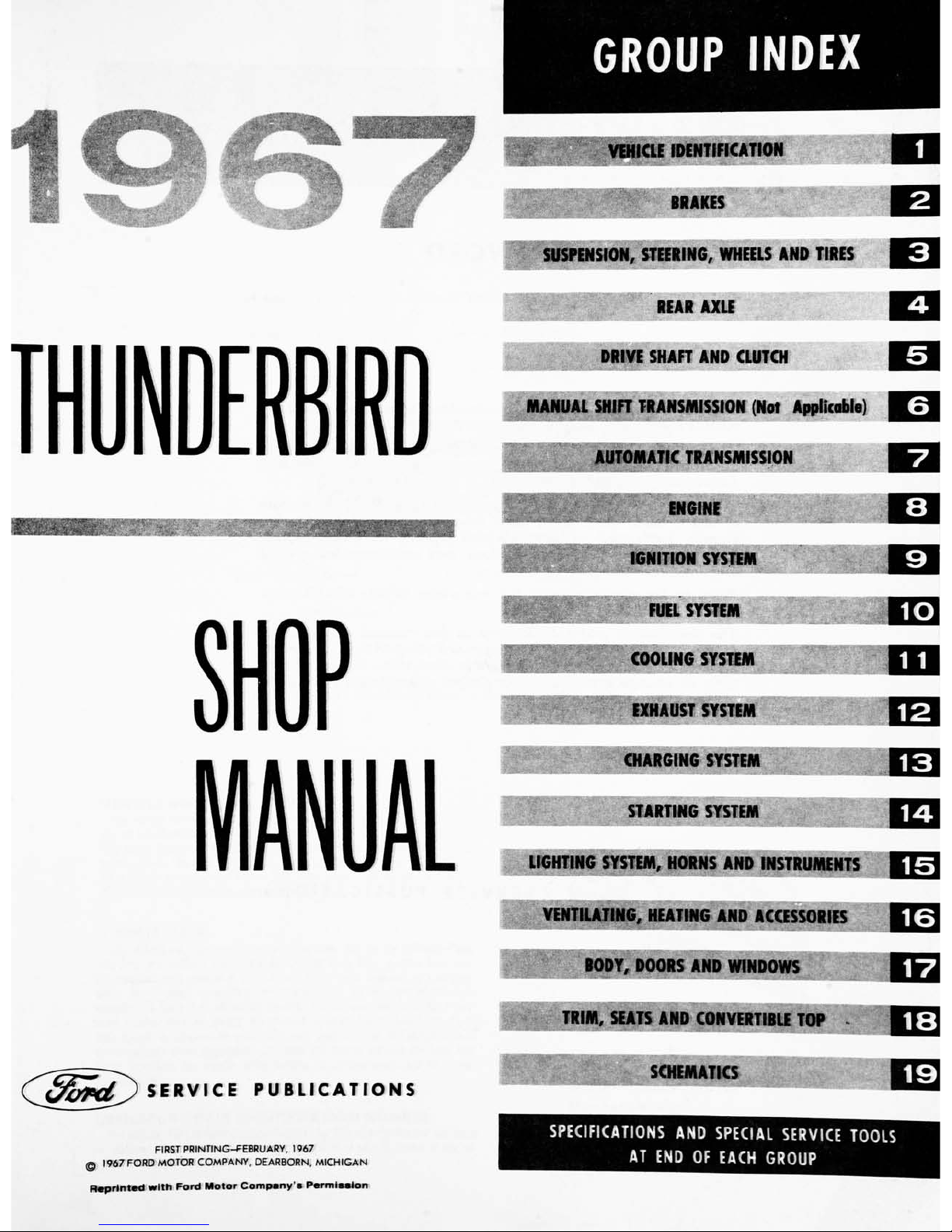
GROUP
INDEX
(^Bo^d^)
SERVICE
PUBLICATIONS
FIRST
PRINTING-FEBRUARY,
1967
1967
FORD
MOTOR
COMPANY,
DEARBORN,
MICHIGAN
Reprinted
with
Ford
Motor
Company's
Permission
VEHICLE
IDENTIFICATION
BRAKES
SUSPENSION,
STEERING,
WHEELS
AND
TIRES
REAR
AXLE
DRIVE
SHAFT
AND
CLUTCH
MANUAL
SHIFT
TRANSMISSION
(Not
Applicable)
AUTOMATIC
TRANSMISSION
ENGINE
IGNITION
SYSTEM
FUEL
SYSTEM
COOLING
SYSi
AUST
SYSTEM
CHARGING
SYST
STARTING
SYSTEM
LIGHTING
SYSTEM,
HORNS
AND
INSTRUMENTS
VENTILATING,
HEATING
AND
ACCESSORIES
BODY,
DOORS
AND
WINDOWS
!M,
SEATS
AND
CONVERTIBLE
TOP
SCHEMATICS
ED
SPECIFICATIONS
AND
SPECIAL
SERVICE
TOOLS
AT
END
OF
EACH
GROUP
FOREWORD
This
shop
manual
provides
the
Service
Technician
with
infor
mation
for
the
proper
servicing
of
the
1967
Thunderbird.
The
maintenance
schedule
and
procedures
for
maintenance
oper
ations
are
published
in
the
1967
Passenger
Car
Maintenance
and
Lubrication
Manual.
The
information
in
this
manual
is
grouped
according
to
the
type
of
work
being
performed,
such
as
diagnosis
and
testing,
fre
quently
performed
adjustments
and
repairs,
in-vehicle
adjust
ments,
overhaul,
etc.
Specifications
and
recommended
special
tools
are
included.
Refer
to
the
opposite
page
for
important
vehicle
identification
data.
The
descriptions
and
specifications
in
this
manual
were
in
effect
at
the
time
this
manual
was
approved
for
printing.
The
Ford
Motor
Company
reserves
the
right
to
discontinue
models
at
any
time,
or
change
specifications
or
design,
without
notice
and
with
out
incurring
obligation.
~&JJS
SERVICE
PUBLICATIONS

Vehicle
Identification
1-1
GROUP
1
I
ASSEMBLY
PLANT
CODE
MODEL
YEAR
CODE
BODY
SERIAL
CODE
ENGINE
CODE
CONSECUTIVE
UNIT
NUMBER
BODY
TYPE
CODE
COLOR
CODE
TRIM
CODE
TRANSMISSION
CODE
REAR
AXLE
CODE
DISTRICT
or
DISTRICT
AND
SPECIAL
EQUIPMENT CODE
N
1S88-A
p/G.
7
Typical
Warranty
Plate
Thunderbird
VEHICLE
WARRANTY
NUMBER
The
vehicle
warranty
number
is
the
first
line
of
numbers
and
letters
appear
ing
on
the
Warranty
Plate
(Fig.
1).
The
first
number
indicates
the
model
year.
The
letter
following
the
model
year
number
indicates
the
manufacturing
as
sembly
plant.
The
next
two
numbers
designate
the
Body
Serial
Code
followed
by
a
letter
expressing
the
Engine
Code.
The
group
of
six
digits
remaining
on
the
first
line
indicate
the
Consecutive
Unit
Number.
VEHICLE
DATA
The
vehicle
data
appears
on
the
second
or
lower
line
on
the
Warranty
Plate.
The
first
two
numbers
and
a
letter
identify
the
Body
Style.
A
letter
or
a
num
ber
appears
next
indicating
the
Exterior
Paint
Color
followed
by
a
number-
letter
combination
designating
the
Interior
Trim.
To
the
right
of
this
code
appears
the
Date
Code
indicating
the
date
the
car
was
manufactured.
A
two-
digit
number
next
designates
the
district
in
which
the
car
was
ordered
and
may
appear
in
conjunction
with
a
Domestic
Special
OrderorForeign
Special
Order
number
when
applicable.
The
final
two
spaces
indicate
the
Rear
Axle
Ratio
(numbers
for
regular
axles,
letters
for
locking-types)
and
the
Trans
mission
type.
OFFICIAL
VEHICLE
IDENTIFICATION
NUMBER
The
official
Vehicle
Identification
Number
for
title
and
registration
purposes
is
stamped
on
the
cowl
top
panel
tab
right
hand
side
of
center
in
the
en
gine
compartment
(Fig.
2).
N
1526
-A
FIG.
2
Thunderbird
Identification
Number
Location
1-2
GROUP
1
-Vehicle
Identification
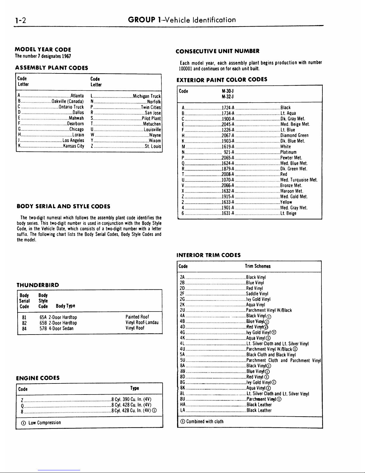
MODEL
YEAR
CODE
The
number
7
designates
1967
ASSEMBLY
PLANT
CODES
A
Atlanta
B
Oakville
(Canada)
C
Ontario
Truck
D
Dallas
E
Mahwah
F
Dearborn
G
Chicago
H
Lorain
J
Los
Angeles
K
Kansas
City
L
Michigan
Truck
N
Norfolk
P
Twin
Cities
R
San
Jose
S
Pilot
Plant
T
Metuchen
U
Louisville
W
Wayne
Y
Wixom
Z
St.
Louis
BODY
SERIAL
AND
STYLE
CODES
The
two-digit
numeral
which
follows
the
assembly
plant
code
identifies
the
body
series.
This
two-digit
number
is
used
in
conjunction
with
the
Body
Style
Code,
in
the
Vehicle
Date,
which
consists
of
a
two-digit
number
with
a
letter
suffix.
The
following
chart
lists
the
Body
Serial
Codes,
Body
Style
Codes
and
the
model.
CONSECUTIVE
UNIT
NUMBER
Each
model
year,
each
assembly
plant
begins
production
with
number
100001
and
continues
on
for
each
unit
built.
EXTERIOR
PAINT
COLOR
CODES
A
1724-A
B
1734-A
C
1900-A
E
2045-A
F
1226-A
H
2067-A
K
1903-A
M
1619-A
N
921-A
P
2065-A
Q
1624-A
R
1879-A
T
2008-A
U
1070-A
V
2066-A
X
1632-A
Z
1915-A
2
1633-A
4
1901-A
6
1631-A
Black
Lt.
Aqua
Dk.
Gray
Met.
Med.
Beige
Met.
Lt.
Blue
Diamond
Green
Dk.
Blue
Met.
White
Platinum
Pewter
Met.
Med.
Blue
Met.
Dk.
Green
Met.
Red
Med.
Turquoise
Met.
Bronze
Met.
Maroon
Met.
Med.
Gold
Met.
Yellow
Med.
Gray
Met.
Lt.
Beige
INTERIOR
TRIM
CODES
THUNDERBIRD
Body
Body
Serial
Style
Code
Code
Body
Type
81
82
84
65A
2-Door
Hardtop
65B
2-Door
Hardtop
57B
4-Door
Sedan
Painted
Roof
Vinyl
Roof-Landau
Vinyl
Roof
ENGINE
CODES
Code
Type
Z
8
Cyl.
390
Cu.
In.
(4V)
n
8
Cyl.
428
Cu.
In.
(4V)
8
8
Cyl.
428
Cu.
In.
(4V)
Low
Compression
Code
Trim
Schemes
2A.
2B.
2D.
2F.
2G.
2K.
2U.
4A.
4B.
4D.
4G.
4K.
4L.
4U.
5A.
5U.
8A.
86.
8D.
8G.
8K.
81.
8U.
HA.
LA.
.Black
Vinyl
.Blue
Vinyl
.Red
Vinyl
.Saddle
Vinyl
.Ivy
Gold
Vinyl
.Aqua
Vinyl
.Parchment
Vinyl
W/Black
.Black
Vinyl
q
Blue
Vinyl
.Red
Vinyt
.Ivy
Gold
Vinyl
.Aqua
Vinyl
.Lt.
Silver
Cloth
and
Lt.
Silver
Vinyl
.Parchment
Vinyl
W/Black
.Black
Cloth
and
Black
Vinyl
.Parchment
Cloth
and
Parchment
Vinyl
.Black
Vinyl
.Blue
Vinyt
.Red
Vinyl
.Ivy
Gold
Vinyl
.Aqua
Vinyl
Lt.
Silver
Cloth
and
Lt.
Silver
Vinyl
..Parchment
Vinyl
.Black
Leather
..Black
Leather
Combined
with
cloth
GROUP
1
-Vehicle
Identification
1-3
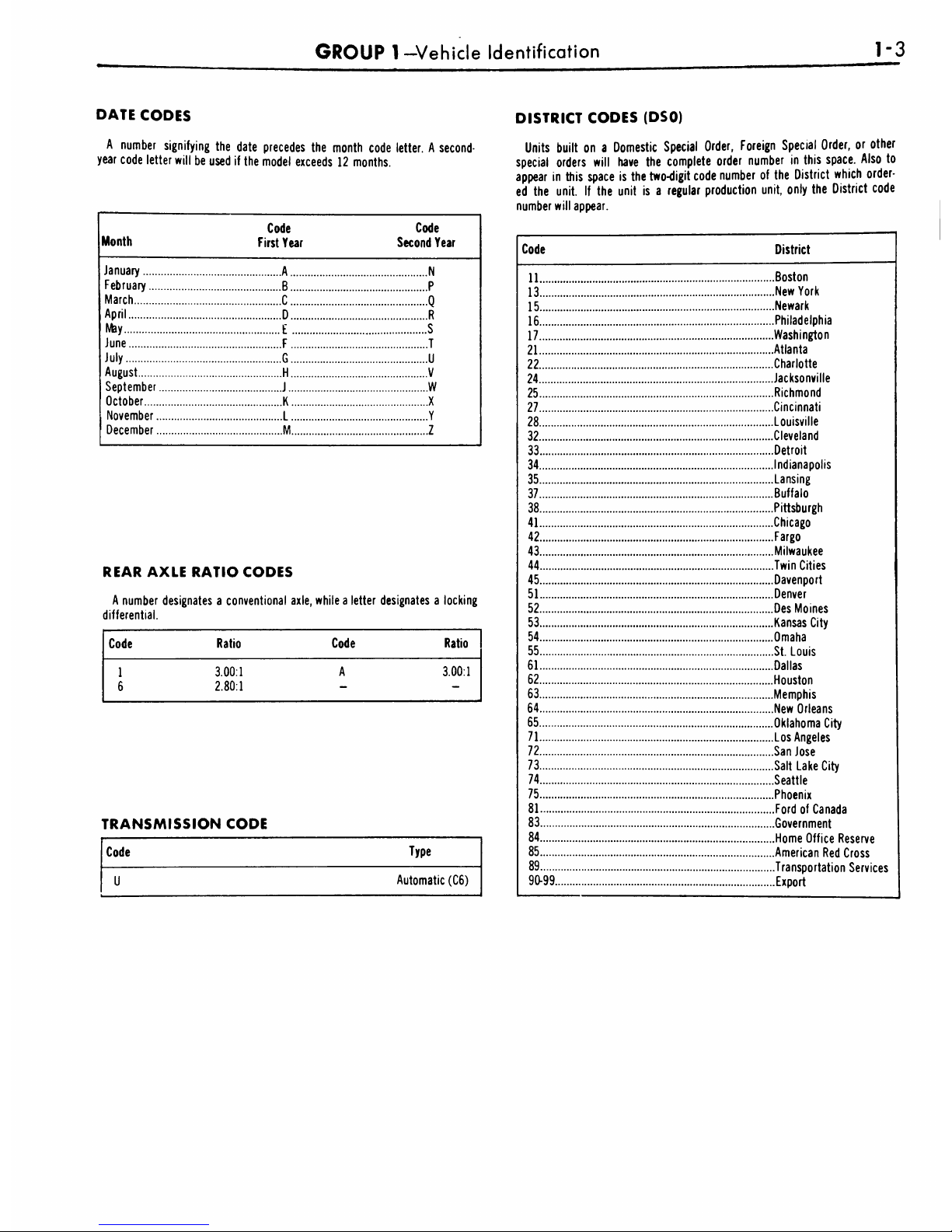
DATE
CODES
A
number
signifying
the
date
precedes
the
month
code
letter.
A
second-
year
code
letter
will
be
used
if
the
model
exceeds
12
months.
January
February...
March
April
May
June
July
August
September
October....
November
December
Code
First
Year
Code
Second
Year
A
N
B
P
C
Q
D
R
E
S
F
T
G
U
H
V
J
W
K X
L
Y
M
Z
REAR
AXLE
RATIO
CODES
A
number
designates
a
conventional
axle,
while
a
letter
designates
a
locking
differential.
TRANSMISSION
CODE
Code
Type
Automatic
(C6)
DISTRICT
CODES
(DSO)
Units
built
on
a
Domestic
Special
Order,
Foreign
Special
Order,
or
other
special
orders
will
have
the
complete
order
number
in
this
space.
Also
to
appear
in
this
space
is
the
two-digit
code
number
of
the
District
which
order
ed
the
unit.
If
the
unit
is
a
regular
production
unit,
only
the
District
code
number
will
appear.
Code
District
11
Boston
13
New
York
15
Newark
16
Philadelphia
17
Washington
21
Atlanta
22
Charlotte
24
Jacksonville
25
Richmond
27
Cincinnati
28
Louisville
32
Cleveland
33
Detroit
34
Indianapolis
35
Lansing
37
Buffalo
38
Pittsburgh
41
Chicago
42
Fargo
43
Milwaukee
44
Twin
Cities
45
Davenport
51
Denver
52
Des
Moines
53
Kansas
City
54
Omaha
55
St.
Louis
61
Dallas
62
Houston
63
Memphis
64
New
Orleans
65
Oklahoma
City
71
Los
Angeles
72
San
Jose
73
Salt Lake
City
74
Seattle
75
Phoenix
81
Ford
of
Canada
83
Government
84
Home
Office
Reserve
85
American
Red
Cross
89
Transportation
Services
90-99
Export
2-1
akes
GROUP
2
PART
2-1
PAGE
General
Brake
Service
2-1
PART
2-2
Brake
System
2-8
PART
2-3
Specifications
PAGE
2-26
PART
2-1-Genera/
Brake
Service
Section
Page
1
Diagnosis
and
Testing
2-1
Brake
Systems
Tests
2-1
Road
Test
2-1
Disc
Brake
Trouble
Symptoms
and
Possible
Causes
2-3
Drum
Brake
Trouble
Symptoms
and
Possible
Causes
2-4
2
Common
Adjustments
andRepairs
2-5
Parking
Brake
Linkage
Adjustment
2-5
PAGE
Section
Power
Brake
Master
Cylinder
Push Rod
Adjustment
2-5
Hydraulic
System
Bleeding
and
Centralizing
of
the
Differential
Valve
2-6
3
Cleaning
and
Inspection
2-7
Front
Brakes
2-7
Rear
Brakes
2-7
Booster
Unit
2-7
DIAGNOSIS
AND
TESTING
BRAKE
SYSTEM
TESTS
BRAKE
FLUID
LEVEL
AND
HYDRAULIC
SYSTEM
Always
check
the
fluid
level in
the
brake
master
cylinder
reservoirs
before
performing
the
test
procedures.
If
the
fluid
level
is
not
within
1/4
to
1/2
inch
of
the
top
of
the
master
cylinder
reservoirs,
add
Rotunda
Brake Fluid
Extra
Heavy
Duty
C6AZ19542-A
(ESA-M6C25-A).
The
disc
brake
extra
heavy
duty
brake
fluid
is
colored
for
identification
purposes.
Do
not
mix
low
temperature
brake
fluids
with
the
specified
brake
fluid.
1.
Turn
the
ignition
dual
master
cylinder
brake
system
switch
to
the
ACC
or
ON
position.
If
the
light
on
the
brake
warning
lamp
remains
on,
the
condition
may
be
caused
by
a
defective
switch,
grounded
switch
wires
or
the
differen
tial
pressure
valve
is
not
centered.
Centralize
the
differential
pressure
valve
as
outlined
under
Bleeding
the
Brake
System
in
this
section
of
the
manual.
If
the
warning
light
re
mains
on,
the
condition
may
be
caus
ed
by
a
defective
switch,
grounded
switch
wires
or
the
differential
pressure
valve
is
not
centered.
Centralize
the
dif
ferential
pressure
valve
as
outlined
un
der
Bleeding
the
Brake
System
in
this
section
of
the
manual.
If
the
warn
ing
light
remains
on,
check
the
switch
connector
and
wire
for
a
grounded
condition
and
repair
or
replace
the
wire
assembly.
If
the
condition
of
the
wire
is
good,
replace
the
brake
warn
ing
lamp
switch.
2.
If
the
brake
warning
lamp
does
not
light
when
a
pressure
dif
ferential
condition
exists
in
the
brake
system,
the
warning
lamp
may
be
burned
out,
the
warning
lamp
switch
is
inoperative
or
the
switch
to
lamp
wiring
has
an open
circuit.
Check
the
bulb
and
replace
it,
if
required.
Check
the
switch
to
lamp
wires
for
an
open
circuit
and
repair
or
replace
them,
if
required.
If
the
warning
lamp
still
does
not
light,
replace
the
switch.
BRAKE
PEDAL FREE
HEIGHT
AND
TRAVEL
MEASUREMENTS
With
the
engine
running
for
full
power
brake
operation,
measure
the
brake
pedal
free
height,
and
check
the
brake
pedal
travel
with
the
use
of
the
Brake
Pedal
Pressure
Gauge,
Tool
WRE-500-50
as
follows:
Brake
Pedal
Free
Height
Measurement
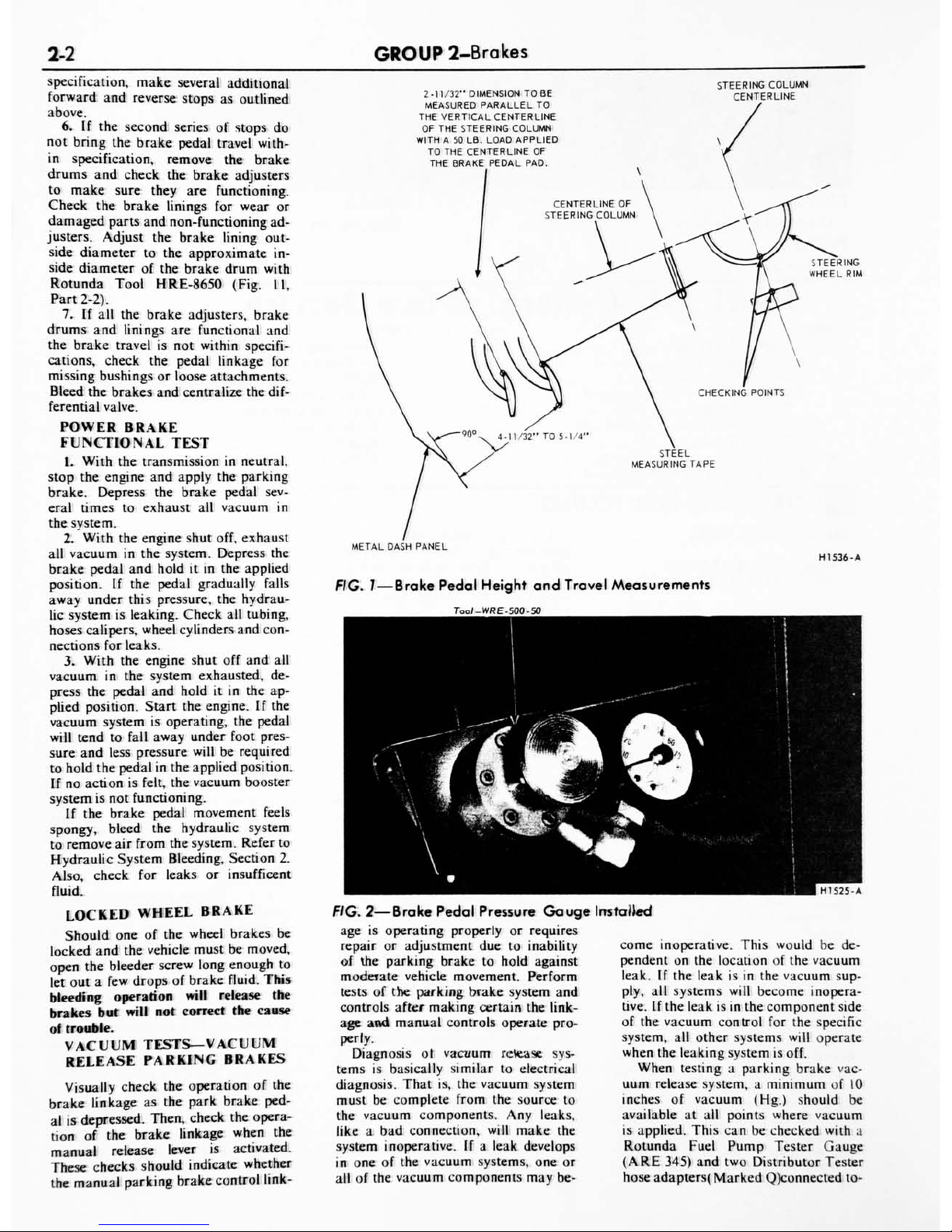
1.
Insert
a
slender,
sharp
point
ed
prod
through
the
carpet
and
sound
deadener
to
the
dash
panel metal
and
measure
the
distance
to the
brake
pedal
(Fig.
1).
2.
If
the
position
of
the
pedal
is
not
within
specification,
check
the
brake
pedal
linkage
for
missing
bushings
or
loose
attaching
bolts
and
replace
them,
if
required.
3.
If
the
pedal
free
height
is
still
out
of
specification,
check
the
brake
pedal
booster
or
master
cylinder
to
be
sure
the
correct
parts
are
installed.
Replace
the
defective
parts
as
neces
sary.
Brake
Pedal
Travel
Measurement
1.
Install
a
Brake Pedal
Effort
Gauge
on
the
brake
pedal pad
(Fig.
2).
2.
Hook
a
steel
measuring
tape
to
the
brake
pedal
as
shown
in
Fig.
1.
Measure
and
record
the
distance
from
the
brake
pedal
free
height
po
sition
to
the
reference
point,
which
is
at
the
six
o'clock
position
on
the
steering
wheel
rim.
3.
With
the
steel
tape
still
hooked
to
the
brake
pedal
depress
the
brake
pedal
by
pressing
downward
on
the
brake
pedal
effort
gauge.
Apply
a
50
pound
load
to
the
center
of
the
pedal
by
observing
the
pressure
gauge,
and
measure
the
distance
from
the
brake
pedal
to
the
fixed
ref
erence
point
on
the
steering
wheel
rim
parallel
to
the
centerline
of
the
steer
ing
column.
4.
Tie
difference
between
the
brake
pedal
free
height
and
the
depressed
ped
al
measurement
under
a
50
pound
load
should
be
within
the
specified
max
imum
pedal
travel
service
specification
Bin
Fig.
1.
5.
If
the
pedal
travel
is
more
than
the
specified
maximum
shown,
in
Fig.
1,
dimension
B,
make
several
sharp
re
verse
stops
(equivalent
to
50
pounds
pedal
pressure)
with
a
forward
stop
be
fore
each.
Move
the
vehicle
in
reverse
and
forward
for
a
distance
of
approx
imately
ten
feet;
then
apply
the
brakes
sharply
and
hold
the
brake
pedal
down
until
the
vehicle
is
completely
stopped.
This
will
actuate
the
brake
self-adjusters.
If
these
stops
do
not
bring
the
brake
pedal
travel
within
2-2
GROUP
2-Brakes
specification,
make
several
additional
forward
and
reverse
stops
as
outlined
above.
6.
If
the
second
series
of
stops
do
not
bring
the
brake
pedal
travel
with
in
specification,
remove
the
brake
drums
and
check
the
brake
adjusters
to
make
sure
they
are
functioning.
Check
the
brake
linings
for
wear
or
damaged
parts
and
non-functioning
ad
justers.
Adjust
the
brake
lining
out
side
diameter
to
the
approximate
in
side
diameter
of
the
brake
drum
with
Rotunda
Tool
HRE-8650
(Fig.
11,
Part
2-2).
7.
If
all
the
brake
adjusters,
brake
drums
and
linings
are
functional
and
the
brake
travel
is
not
within
specifi
cations,
check
the
pedal
linkage
for
missing
bushings
or
loose
attachments.
Bleed
the
brakes
and
centralize
the
dif
ferential
valve.
POWER
BRAKE
FUNCTIONAL
TEST
1.
With
the
transmission
in
neutral,
stop
the
engine
and
apply
the
parking
brake.
Depress
the
brake
pedal
sev
eral
times
to
exhaust
all
vacuum
in
the
system.
2.
With
the
engine
shut
off,
exhaust
all
vacuum
in
the
system.
Depress
the
brake
pedal
and
holditin
the
applied
position.
If
the
pedal
gradually
falls
away
under
this
pressure,
the
hydrau
lic
system
is
leaking.
Check
all
tubing,
hoses
calipers,
wheel
cylinders
and
con
nections
for leaks.
3.
With
the
engine
shut
off
and
all
vacuum
in
the
system
exhausted,
de
press
the
pedal
and
hold
it
in
the
ap
plied
position.
Start
the
engine.
If
the
vacuum
system
is
operating,
the
pedal
will
tend
to
fall
away
under
foot
pres
sure
and
less
pressure
will
be
required
to
hold
the
pedal
in
the
applied
position.
If
no
action
is
felt,
the
vacuum
booster
system
is
not
functioning.
If
the
brake
pedal
movement
feels
spongy,
bleed
the
hydraulic
system
to
remove
air
from
the
system.
Refer
to
Hydraulic
System
Bleeding,
Section
2.
Also,
check
for
leaks
or
insufficent
fluid.
LOCKED
WHEEL
BRAKE
Should
one
of
the
wheel
brakes
be
locked
and
the
vehicle
must
be
moved,
open
the
bleeder
screw
long
enough
to
let
out
a
few
drops
of
brake
fluid.
This
bleeding
operation
will
release
the
brakes
but
will
not
correct
the
cause
of
trouble.
VACUUM
TESTS
VACUUM
RELEASE
PARKING
BRAKES
Visually
check
the
operation
of
the
brake
linkage
as
the
park
brake
ped
al
is
depressed.
Then,
check
the
opera
tion
of
the
brake
linkage
when
the
manual
release
lever
is
activated.
These
checks
should
indicate
whether
the
manual
parking
brake
control
link-
2-11/32"
DIMENSION
TO
BE
MEASURED
PARALLEL
TO
THE
VERTICAL
CENTERLINE
OF
THE
STEERING
COLUMN
WITH
A
50
LB.
LOAD
APPLIED
TO
THE
CENTERLINE
OF
THE
BRAKE
PEDAL
PAD.
STEERING
COLUMN
CENTERLINE
STEEL
MEASURING
TAPE
METAL
DASH
PANEL
FIG.
7
Brake
Pedal
Height
and
Travel
Measurements
Too/-WRE-500-50
H1536-A
^m
'
*
^1
W&F
'
M^m
^^^^H
'
'
*/f]
^MC^^
^'
^
Vtfl
^p
*
^B
jj^
jLjHJ
SkR
m
iL
WL*
jH
Ik.*
>afl
HnC^I
MPP
0'H
HI
525
-A
FIG.
2
Brake
Pedal
Pressure
Gauge
age
is
operating
properly
or
requires
repair
or
adjustment
due
to
inability
of
the
parking
brake
to
hold
against
moderate
vehicle
movement.
Perform
tests
of
the
parking
brake
system
and
controls
after
making
certain
the
link
age
and
manual
controls
operate
pro
perly.
Diagnosis
ot
vacuum
rctease
sys
tems
is
basically
similar
to
electrical
diagnosis.
That
is,
the
vacuum
system
must
be
complete
from
the
source
to
the
vacuum
components.
Any
leaks,
like
a
bad
connection,
will
make
the
system
inoperative.
If
a
leak
develops
in
one
of
the
vacuum
systems,
one
or
all
of
the
vacuum
components
may
be-
Ins
tailed
come
inoperative.
This
would
be
de
pendent
on
the
location
of
the
vacuum
leak.
If
the
leak
is
in
the
vacuum
sup
ply,
all
systems
will
become
inopera
tive.
If
the
leak
is
in
the
component
side
of
the
vacuum
control
for
the
specific
system,
all
other
systems
will
operate
when
the
leaking
system
is
off.
When
testing
a
parking
brake
vac
uum
release
system,
a
minimum
of
10
inches
of
vacuum
(Hg.)
should
be
available
at
all
points
where
vacuum
is
applied.
This
can
be
checked
with
a
Rotunda
Fuel
Pump
Tester
Gauge
(ARE
345)
and
two
Distributor Tester
hose
adapters(
Marked
Q)connected
to-
PART
2-1
-Gen
era
I
Brake
Service
2-3
TROUBLE
SYMPTOMS
POSSIBLE
CAUSES
OF
TROUBLE
3
>
ed
la
H
"3
O
5
CU
>
If)
J
o
X
m
"E.
E
3
0-
"3
o
1>
5
u
o
/>
u
c
JC
00
3
o
ed
u.
03
a-*
aa
o
{=
"c3
"8
Cu
>
to
i/>
CU
U
X
UJ
3
Dm
UL
8
ed
~Z
tc
o
*s
u-
o
c
rt
oo
c
*a>
Q
00
c
la
3
Q
o
S
X
C/l
rt
u
CQ
la
4>
o
c
">>
U
1
JC
JX
e
<L>
-J
c
o
aaal
O
<
(30
c
12
ed
aa
OQ
C
It
>
g
la
o
00
c
15
ed
la
0
CU
(A
la
o.
Q
on
"ed
"O
V
Oa
C
V
t>
<*-
taa
UJ
oo
c
IS
ed
aa
OQ
O
Z
D.
<
o
z
o
Q
V
(/>
>>
>
CJ
9*
V
06.
V
J=
*-
la
o
la.
l/>
J*
ed
la
OS
c
ed
Oa
-c
C/>
ed
Q
la
o
la
o
o
u-
"O
la
ed
*
O
H
</>
>
o
"ed
3
"O
ed
la
o
"ed
"8
Oa
aJ
cn
>
ed
a
E
ed
al
oo
c
'c
a>
00
Hi
a-
o
Z
CM
Q
a
E
ed
?J
oo
C
'c
la
ed
Shoe
and
Lining
Knock-back
after
Violent
Cornering
or
Rough
Road
Travel
X
Shoe
and
Lining
Assembly
not
Properly
Seated
or
Positioned
X
X
X
Leak
or
Insufficient
Fluid
in
System
or
Caliper
X
X
X
X
Loose
Wheel
Bearing
Adjustment
X X
Damaged
or
Worn
Caliper
Piston
Seal
X
X
X
Improper
Master
Cylinder Push
Rod
Adjustment
X
Excessive
Rotor
Runout
or
Out-of-Parallel
X
Incorrect
Tire
Pressure
X
X
Frozen
or
Seized
Pistons
X
X X
X
Brake
Fluid,
OilorGrease
on
Linings
X
X
X
X
Shoe
and
Lining
Worn
Below
Specifications
X
Proportioning
Valve
Malfunction
X
X
Booster
Inoperative
X
Caliper
Out
of
Alignment
with
Rotor
X
X
Loose
Caliper
Attachment
X X
X
X
Metering
Valve
Seal
Leaks
X
Excessive
Clearance
Between Shoe
and
Caliper
or
Between
Shoe
and
Splash
Shield
X
Shoe Hold
Down
Clips
Missing
or
Improperly
Positioned
X
Operator
Riding
Brake
Pedal
X
Scores
in
the
Cylinder
Bore
X
Corrosion
Build-
Up
in
the
Cylinder
Bore
or
on
the
Piston
Surface
X
X
X
Bleeder
Screw
Still
Open
X
X
Caliper
Out-of-Parallel
with
Rotor
X
One
Section
Dual
Brake
System
is
Inoperative
X
X
Differential
Pressure
Valve
is
Not
Centered
X
Wiring
to
Warning
Lamp
SwitchisGrounded
X
Warning
Lamp
Switch
is
Grounded
X
Warning
Lamp
is
Burned
Out
X
Warning
Lamp
Switch
Has
an
Open
Circuit
X
Warning
Lamp
Switch
is
Inoperative
X
Wiring
to
Warning
Lamp
Has
Open
Circuit
X
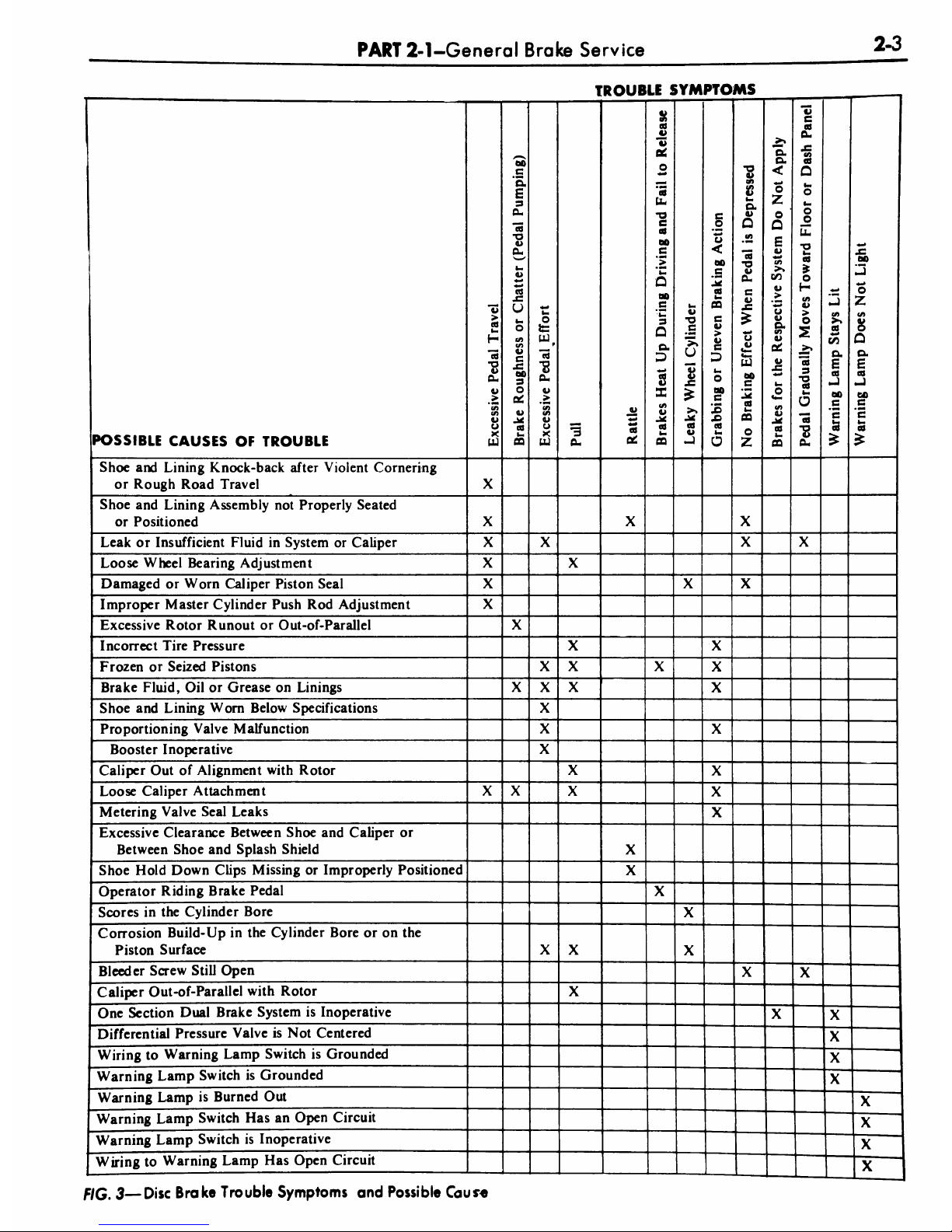
FIG.
3
Disc
Brake
Trouble
Symptoms
and
Possible
Caus*e
2-4
GROUP
2-Brakes
TROUBLE
SYrV
IPTC
>MS
POSSIBLE
CAUSES
OF
TROUBLE
cd
la
Q
u
_<:
ed
la
OQ
a
c
O
QO
cd
a-
0
</>
ii
cd
la
OQ
<
rt
-o
ii
Oa
la
X
ed
o
ii
Cm
>
c
o
Q.
ii
oo
u
c
o
o
(/>
*3
cu
la
rt
u
1/5
aJ
"ej
J.
u
c
O
a
ed
u
U
JX
&
la
CQ
4>
>
cd
la
H
"cd
"8
Cu
a
>
8
X
UJ
la
o
Lu
O
(/>
8
0
"cd
3
"O
cd
la
o
"rt
"O
o>
CU
c
ii
>
ii
c
<s>
ii
-at
rt
la
09
09
cd
U
06*
la
<aa
<
JX
o
u
ii
o
-C
C/3
c/i
cd
la
CQ
00
c
15
X>
ed
la
a
la
o
*o
Z
"o.
o.
<
o
Z
o
Q
</
u
cd
la
CQ
<
o
z
o
Q
E
a
00
a
>
o
a
o.
(/>
V
ii
la
o
u-
cn
U
ed
la
CQ
in
c/>
>>
2
i/5
o.
E
ed
aJ
oo
e
c
cej
ii
c
cd
Cu
JC
(/
cd
Q
la
o
la
o
o
u-
T3
la
cd
O
H
t/>
a
>
o
"rt
3
o
rt
la
o
"rt
O
a
Oa
JB
00
aj
o
Z
Ul
1>
O
Q
Q.
E
aJ
oo
c
'c
la
Mechanical
Resistance
at
Pedal
or
Shoes
X
X
Brake
Line
Restricted
X
X
X
X
Leaks
or
Insufficient Fluid
X
X
X
X
X
Improper
Tire
Pressure
X
X
Distorted
or
Improperly
Adjusted
Brake
Shoe
X
X
X
X
X
X X
Faulty
Retracting
Spring
X
X
Drum
Out
of
Round
X
X X
Lining
Glazed
or
Worn
X
X
X
X
X
X X
Oil
or
Grease
on
Lining
X
X
X X X X
Loose
Carrier
Plate
X X
X
Loose
Lining
X
Scored
Drum
X
X
Dirt
on
Drum-Lining
Surface
X
Faulty
Brake
Cylinder
X X X
X
Dirty
Brake
Fluid
X
X
X
X
Faulty
Master
Cylinder
X
X
X
X
Air
in
Hydraulic
System
X
X
X
X
Self
Adjusters
Not
Operating
X
X
Insufficient
Shoe-to-Carrier
Plate
Lubrication
X
X X
Tire
Tread
Worn
X
Poor
Lining-to-Drum
Contact
X
Loose
Front
Suspension
X
Threads
Left
by
Drum
Turning
Tool
Pulls
Shoe
Sideways
X
1
Cracked
Drum
X
One
Section
Dual
Brake
System
is
Inoperative
x
X
Differential
Pressure
Valve
is
Not
Centered
X
Wiring
to
Warning
Lamp
SwitchisGrounded
X
Warning
Lamp
Switch
is
Grounded
X
Warning
Lamp
is
Burned
Out
X
Warning
Lamp
Switch
Has
an
Open
Circuit
X
Wiring
to
Warning
Lamp
Has
Open
Circuit
1
X
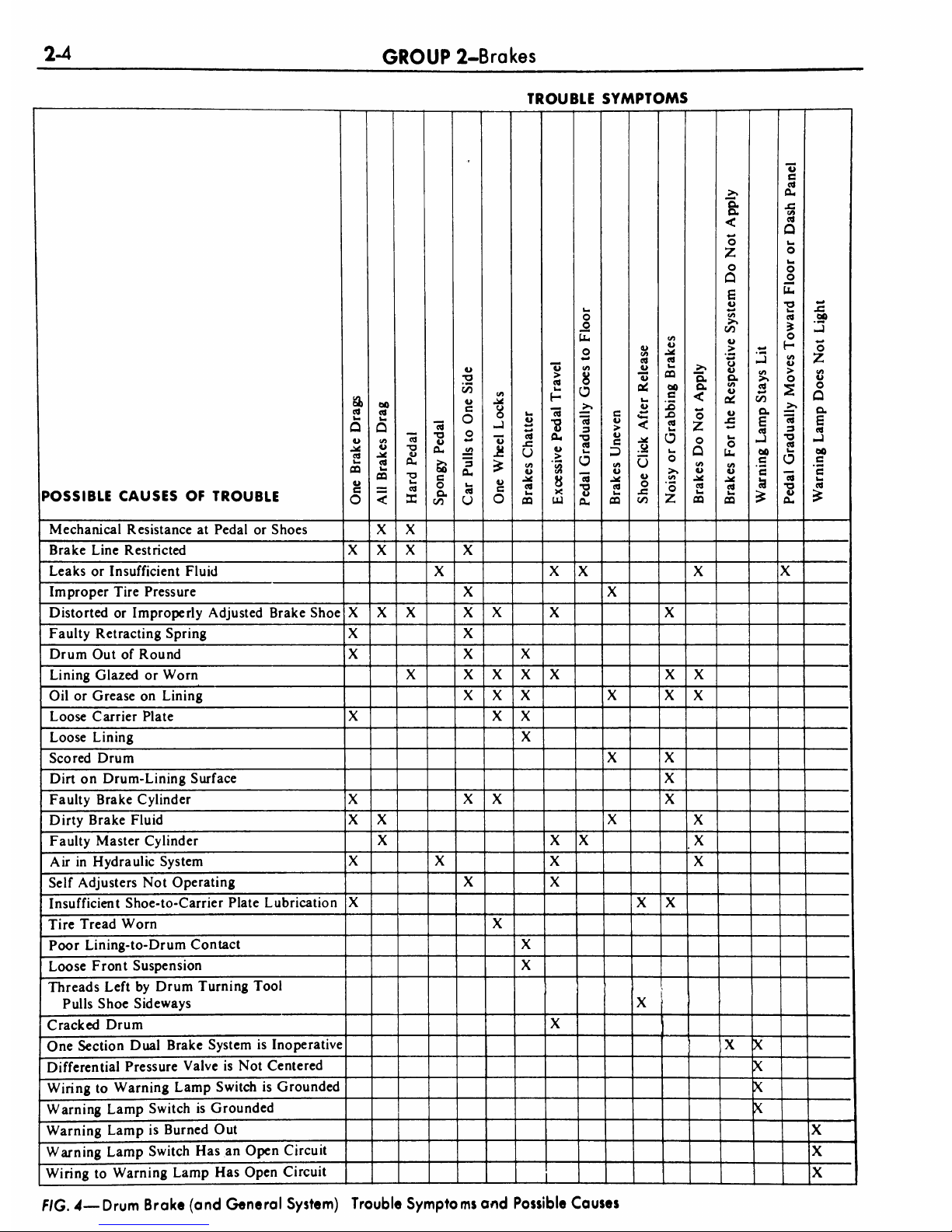
FIG.
4
Drum
Brake
(and
General
System)
Trouble
Symptoms
and
Possible
Causes
PART
2-1
-Gen
era
I
Brake
Service
2-5
gether
with
a
coupling.
This
allows
the
Fuel
Pump
Tester
Gauge
to
be
adapted
to
any
other
vacuum
hose
or
rubber
connector
in
the
vacuum
systems.
Failure
to
maintain
10
inches
of
vacuum
(Hg.)
during
vacuum
sys
tem
tests
could
be
caused
by
a
bad
hose
connection,
resulting
in
a
vacuum
leak.
When
checking
for
vacuum
be
tween
two
points,
trace
the
hose
along
the
entire
routing
to
be
sure
it
is
not
crossed
with
another
hose
and
con
nected
to
the
wrong
connection.
All
of
the
vacuum
parking
brake
release
checks
are
to
be
performed
with
the
engine
running
at
idle
speed.
Leaks
in
the
parking
brake
hoses
or
a
disconnected
or
improperly
con
nected
hose
can
usually
be
found
by
listening
for
a
hissing
sound
along
the
hose
routings.
Under
no
circum
stances
should
air
pressure
be
applied
to
the
vacuum
system
as
the
actuator
diaphragm
in
the
parking
brake
vac
uum
motor
may
be
damaged.
1.
Start
the
engine
and
run
it
at
idle
speed.
With
the
transmission
shift
control
in
neutral,
depress
the
parking
brake
pedal
and
apply
the
parking
brake.
Move
the
transmission
shift
con
trol
to
drive
range
and
observe
the
parking
brake
pedal
to
see
that
the
pedal
moves
upward
and
the
parking
brake
releases.
If
the
parking
brake
releases,
the
parking
brake
vacuum
control
is
working
properly.
2.
If
the
parking
brake
does
not
release,
start
the
engine.
Test
for
vac
uum
at
the
steering
column
neutral
switch
port
in
the
left
junction
block,
vacuum
lines
and
the
parking
brake
release
vacuum
motor.
Use
the
Ro
tunda
Vacuum
and
Fuel
Pump
Tester
ARE
345.
This
can
be
accomplished
by
removing
the
hose
from
each
com
ponent
and
attaching
it
to
the
vacuum
gauge.
Connect
two
distributor
tester
vacuum
hose
adapters
together
with
a
coupling
as
a
connector
to
attach
the
gauge.
A
minimum
of
ten
inches
of
vacuum
is
required
to
actuate
the
parking
brake
vacuum
motor.
Do
not
remove
any
of
the
vacuum
hoses
from
the
junction
block
unless
the
junction
block
is
being
replaced,
as
the
plastic
nipples
are
thin
and
very
brittle
and
damage
may
result.
If
a
minimum
reading
is
not
present
when
checking
each
of
the
aforementioned
compo
nents,
they
must
be
replaced.
COMMON
ADJUSTMENTS
AND
REPAIRS
PARKING
BRAKE
LINKAGE
ADJUSTMENT
Check
the
parking
brake
cables
when
the
brakes
are
fully
released.
If
the
cables
are
loose,
adjust
them
as
follows:
I.
Fully
release
the
parking
brake
pedal
by
pushing
down
the
manual
release
lever.
2.
Raise
the
vehicle.
3.
Depress
the
parking
brake
ped
al
1
1/4
inch
from
its
normal
released
position.
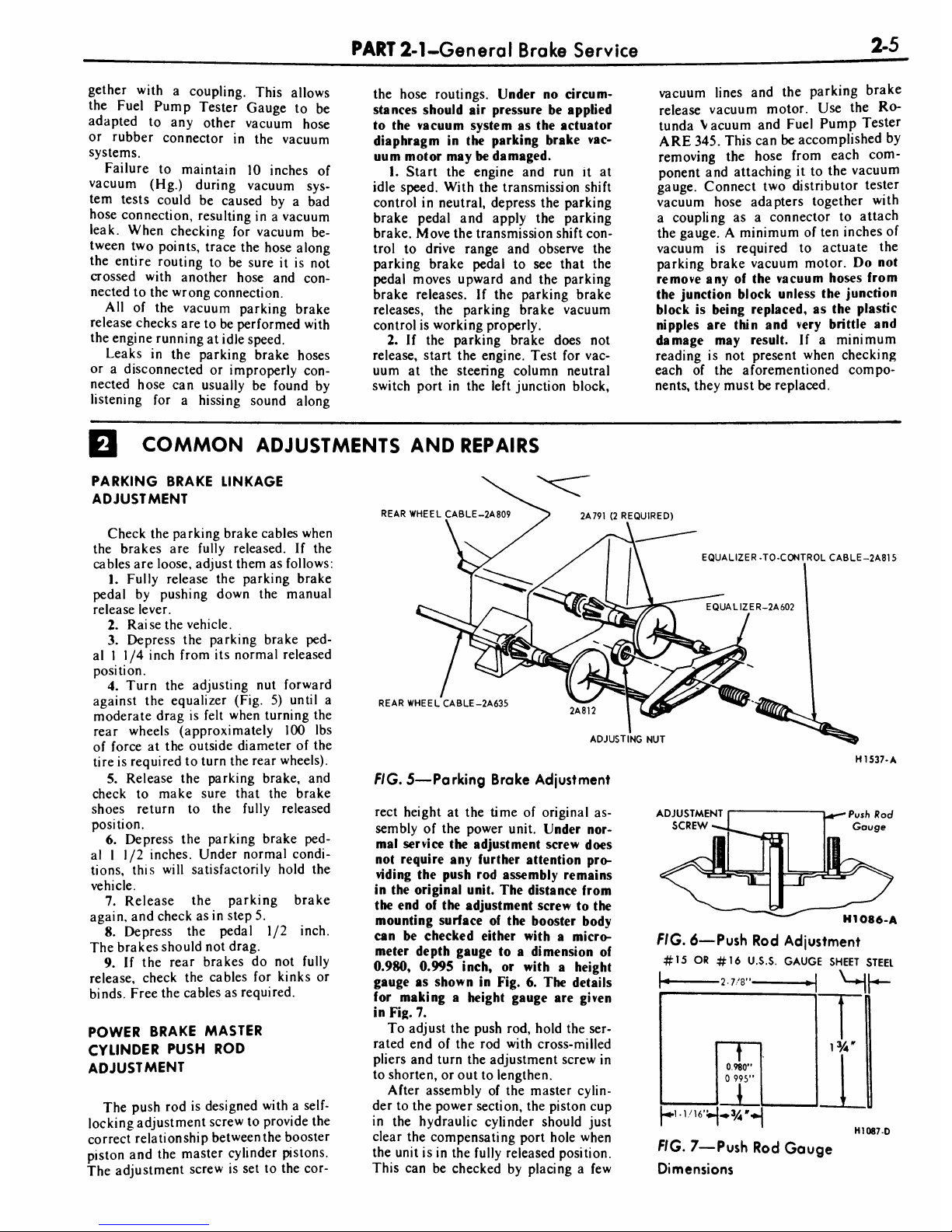
4.
Turn
the
adjusting
nut
forward
against
the
equalizer
(Fig.
5)
until
a
moderate
drag
is
felt
when
turning
the
rear
wheels
(approximately
100
lbs
of
force
at
the
outside
diameter
of
the
tire
is
required
to
turn
the
rear
wheels).
5.
Release
the
parking
brake,
and
check
to
make
sure
that
the
brake
shoes
return
to
the
fully
released
position.
6.
Depress
the
parking
brake
ped
al
1
1/2
inches.
Under
normal
condi
tions,
this
will
satisfactorily
hold
the
vehicle.
7.
Release
the
parking
brake
again,
and
check
as
in
step
5.
8.
Depress
the
pedal
1/2
inch.
The
brakes
should
not
drag.
9.
If
the
rear
brakes
do
not
fully
release,
check
the
cables
for
kinks
or
binds.
Free
the
cables
as
required.
POWER
BRAKE
MASTER
CYLINDER
PUSH
ROD
ADJUSTMENT
The
push
rod
is
designed
with
a
self-
locking
adjustment
screw
to
provide
the
correct
relationship
between
the
booster
piston
and
the
master
cylinder
pistons.
The
adjustment
screw
is
set
to
the
cot-
rear
WHEEL
CABLE-2A809
EQUALIZER.
TO-CONTROL
CABLE-2A815
REAR
WHEEL
CABLE-2A635
ADJUSTING
NUT
FIG.
5
Parking
Brake
Adjustment
rect
height
at
the
time
of
original
as
sembly
of
the
power
unit.
Under
nor
mal
service
the
adjustment
screw
does
not
require
any
further
attention
pro
viding
the
push
rod
assembly
remains
in
the
original
unit.
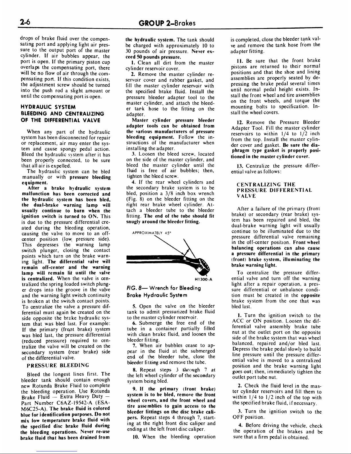
The
distance from
the
end
of
the
adjustment
screw
to
the
mounting
surface
of
the
booster
body
can
be
checked
either
with
a
micro
meter
depth
gauge
to
a
dimension
of
0.980,
0.995
inch,
or
with
a
height
gauge
as
shown
in
Fig.
6.
The
details
for
making
a
height
gauge
are
given
in
Fig.
7.
To
adjust
the
push
rod,
hold
the
ser
rated
end
of
the
rod with
cross-milled
pliers
and
turn
the
adjustment
screw
in
to
shorten,
or
out
to
lengthen.
After
assembly
of
the
master
cylin
der
to
the
power
section,
the
piston
cup
in
the
hydraulic
cylinder
should
just
clear
the
compensating
port
hole
when
the
unit
is
in
the
fully
released
position.
This
can
be
checked
by
placing
a
few
ADJUSTMENT
SCREW
HI
537-
A
Push
Rod
Gauge
H1086-A
FIG.
6
Push
Rod
Adjustment
#15
OR
#16
U.S.S.
GAUGE
SHEET
STEEt
FIG.
7
Push
Rod
Gauge
Dimensions
H1087D
2-6
GROUP
2-Brakes
drops
of
brake
fluid
over
the
compen
sating
port
and
applying
light
air
pres
sure
to
the
output
port
of
the
master
cylinder.
If
air
bubbles
appear,
the
port
is
open.
If
the
primary
piston
cup
overlaps
the
compensating
port,
there
will
be
no
flow
of
air
through
the
com
pensating
port.
If
this
condition
exists,
the
adjustment
screw
should
be
turned
into
the
push
rod
a
slight
amount
or
until
the
compensating
port
is
open.
HYDRAULIC
SYSTEM
BLEEDING
AND
CENTRALIZING
OF
THE
DIFFERENTIAL
VALVE
When
any
part
of
the
hydraulic
system
has
been
disconnected
for
repair
or
replacement,
air
may
enter
the
sys
tem
and
cause
spongy
pedal
action.
Bleed
the
hydraulic
system
after
it
has
been
properly
connected,
to
be
sure
that
all
air
is
expelled.
The
hydraulic
system
can
be
bled
manually
or
with
pressure
bleeding
equipment.
After
a
brake
hydraulic
system
malfunction
has
been
corrected
and
the
hydraulic
system
has
been
bled,
the
dual-brake
warning
lamp
will
usually
continue
to
burn
when
the
ignition
switch
is
turned
to
ON.
This
is
due
to
the
pressure
differential
cre
ated
during
the
bleeding
operation,
causing
the
valve
to
move
to
an
off-
center
position
(low
pressure
side).
This
depresses
the
warning
lamp
switch
plunger,
closing
the
contact
points
which
turn
on
the
brake
warn
ing
light.
The
differential
valve
will
remain
off-center
and
the
warning
lamp
will
remain
lit
until
the
valve
is
centralized.
When
the
valve
is
cen
tralized
the
spring
loaded
switch
plung
er
drops
into
the
groove
in
the
valve
and
the
warning
light
switch
continuity
is
broken
at
the
switch
contact
points.
To
centralize
the
valve
a
pressure
dif
ferential
must
again
be
created
on
the
side
opposite
the
brake
hydraulic
sys
tem
that
was
bled
last.
For
example:
If
the
primary
(front
brake)
system
was
bled
last,
the
pressure
differential
(reduced
pressure)
required
to
cen
tralize
the
valve
will
be
created
on
the
secondary
system
(rear
brake)
side
of
the
differential
valve.
PRESSURE
BLEEDING
Bleed
the
longest
lines
first.
The
bleeder
tank
should
contain
enough
new
Rotunda
Brake
Fluid
to
complete
the
bleeding
operation.
Use
Rotunda
Brake
Fluid
Extra
Heavy
Duty
Part
Number
C6AZ-I9542-A
(ESA-
M6C25-A).
The
brake
fluid
is
colored
blue
for
identification
purposes.
Do
not
mix
low
temperature
brake
fluid
with
the
specified
disc
brake
fluid
during
the
bleeding
operations.
Never
re-use
brake
fluid
that
has
been
drained
from
the
hydraulic
system.
The
tank
should
be
charged
with
approximately
10
to
30
pounds
of
air
pressure.
Never
ex
ceed
50
pounds
pressure.
1.
Clean
all
dirt
from
the
master
cylinder
reservoir
cover.
2.
Remove
the
master
cylinder
re
servoir
cover
and
rubber
gasket,
and
fill
the
master
cylinder
reservoir
with
the
specified
brake
fluid.
Install
the
pressure
bleeder
adapter
tool
to
the
master
cylinder,
and
attach
the
bleed
er
tark
hose
to
the
fitting
on
the
adapter.
Master
cylinder
pressure
bleeder
adapter
tools
can
be
obtained
from
the
various
manufacturers
of
pressure
bleeding
equipment.
Follow
the
in
structions
of
the
manufacturer
when
installing
the
adapter.
3.
Loosen
the
bleed
screw,
located
on
the
side
of
the
master
cylinder,
and
bleed
the
master
cylinder
until
the
fluid
is
free
of
air
bubbles;
then,
tighten
the
bleed
screw.
4.
If
the
rear
wheel
cylinders
and
the
secondary
brake
system
is
to
be
bled,
position
a
3/8
inch
box
wrench
(Fig.
8)
on
the
bleeder
fitting
on
the
right
rear
brake
wheel
cylinder.
At
tach
a
bleeder
tube
to
the
bleeder
fitting.
The
end
of
the
tube
should
fit
snugly
around
the
bleeder
fitting.
APPROXIMATELY
45
H1300-A
FIG.
8
Wrench
for
Bleeding
Brake
Hydraulic
System
5.
Open
the
valve
on
the
bleeder
tank
to
admit
pressurized
brake
fluid
to
the
master
cylinder
reservoir.
6.
Submerge
the
free
end
of
the
tube
in
a
container
partially
filled
with
clean
brake
fluid,
and
loosen
the
bleeder
fitting.
7.
When
air
bubbles
cease
to
ap
pear
in
the
fluid
at
the
submerged
end
of
the
bleeder
tube,
close
the
bteeder
fitting
and
remove
the
tube.
8.
Repeat
steps
3
through
7
at
the
left
wheel
cylinder
of
the
secondary
system
being
bled.
9.
If
the
primary
(front
brake)
system
is
to
be
bled,
remove
the
front
wheel
covers,
and
the
front
wheel
and
tire
assemblies
to
gain
access
to
the
bleeder
fittings
on
the
disc
brake
cali
pers.
Repeat
steps
4
through
7,
start
ing
at
the
right
front
disc
caliper
and
ending
at
the
left
front
disc
caliper.
10.
When
the
bleeding
operation
is
completed,
close
the
bleeder
tank
val
ve
and
remove
the
tank
hose
from
the
adapter
fitting.
11.
Be
sure
that
the
front
brake
pistons
are
returned
to
their
normal
positions
and
that
the
shoe
and
lining
assemblies
are
properly
seated
by
de
pressing
the
brake
pedal
several
times
until
normal
pedal
height
exists.
In
stall
the
front
wheel
and
tire
assemblies
on
the
front
wheels,
and
torque
the
mounting
bolts
to
specification.
In
stall
the
wheel
covers.
12.
Remove
the
Pressure
Bleeder
Adapter
Tool.
Fill
the
master
cylinder
reservoirs
to
within
1/4
to
1/2
inch
from
the
top.
Install
the
master
cylin
der
cover
and
gasket.
Be
sure
the
dia
phragm
type
gasket
is
properly
posi
tioned
in
the
master
cylinder
cover.
13.
Centralize
the
pressure
differ
ential
valve
as
follows:
CENTRALIZING
THE
PRESSURE
DIFFERENTIAL
VALVE
After
a
failure
of
the
primary
(front
brake)
or
secondary
(rear
brake)
sys
tem
has
been
repaired
and
bled,
the
dual-brake
warning
light
will
usually
continue
to
be
illuminated
due
to
the
pressure
differential
valve
remaining
in
the
off-center
position.
Front
wheel
balancing
operations
can
also
cause
a
pressure
differential
in
the
primary
(front)
brake
system,
illuminating
the
brake
warning
light.
To
centralize
the
pressure
differ
ential
valve
and
turn
off
the
warning
light
after
a
repair
operation,
a
pres
sure
differential
or
unbalance condi
tion
must
be
created
in
the
opposite
brake
system
from
the
one
that
was
bled
last.
1.
Turn
the
ignition
switch
to
the
ACC
or
ON
position.
Loosen
the
dif
ferential
valve
assembly
brake
tube
nut
at
the
outlet
port
on
the
opposite
side
of
the
brake
system
that
was
wheel
balanced,
repaired
and/or
bled
last.
Depress
the
brake
pedal
slowly
to
build
line
pressure
until
the
pressure
differ
ential
valve
is
moved
to
a
centralized
position
and
the
brake
warning
light
goes
out;
then,
immediately
tighten
the
outlet
port
tube
nut.
2.
Check
the
fluid
level
in
the
mas
ter
cylinder
reservoirs
and
fill
them
to
within
1/4
to
1/2
inch
of
the
top
with
the
specified
brake
fluid,
if
necessary.
3.
Turn
the
ignition
switch
to
the
OFF
position.
4.
Before
driving
the
vehicle,
check
the
operation
of
the
brakes
and
be
sure
that
a
firm
pedal
is
obtained.
PART
2-1
-Gen
era
I
Brake
Service
2-7
CLEANING
AND
INSPECTION
FRONT
BRAKES
1.
Remove
the
wheel
and
tire,
brake
shoe
retainers,
and
the
shoe
and
linings
as
outlined
in
Part
2-2,
Section
2.
2.
Make
three
thickness
measure
ments
with
a
micrometer
across
the
middle
section
of
the
shoe
and
lining.
Take
one
reading
at
each
side
and
one
in
the
center.
If
the
assembjv
has
worn
to
a
thickness
of
0.231
inch
(Shoe
and
lining
together)
or
0.066
inch
(Lining
material
only)
at
any
one
of
the
three
measuring
locations,
or
if
the
lining
shows
evidence
of
brake
fluid
or
oil
contamination,
replace
all
(4)
shoe
and
linings
on
both
front
wheels.
3.
Check
caliper
to
spindle
attach
ing
bolt
and
caliper
bridge
bolt
tor
que.
Torque
them
to
specification
if
required.
4.
To
check
rotor
runout,
first
elimi
nate
the
wheel
bearing
end
play
by
tightening
the
adjusting
nut
to
5
inch
pounds
torque.
After
tightening
the
nut,
check
to
see
that
the
rotor
can
still
be
rotated.
5.
Clamp
a
dial
indicator
to
the
caliper
housing
so
that
the
stylus
contacts
the
rotor
at
a
point
approx
imately
1
inch
from
the
outer
edge.
Rotate
the
rotor
and
take
an
indica
tor
reading.
If
the
reading
exceeds
0.002
inch
total
lateral
runout
on
the
indicator,
replace
or
resurface
the
disc
brake
rotor.
The
following
require
ments
must
be
met
when
resurfacing
disc
brake
rotors:
Rotunda
Disc
Brake
Attachment
FRE-2249-2
is
the
only
approved
tool
to
be
used
to
refinish
the
disc
brake
rotors.
The
step-by-step
resurfacing
procedure
provided
with
the
tool
must
be
adhered
to.
The
finished
braking
surfaces
of
the
rotor
must
be
flat
and
parallel
within
0.0007
inch;
lateral
runout
must
not
exceed
0.002
inch
total
in
dicator
reading,
and
the
surface
fin
ish
of
the
braking
surfaces
are
to
be
85/15
micro
inches.
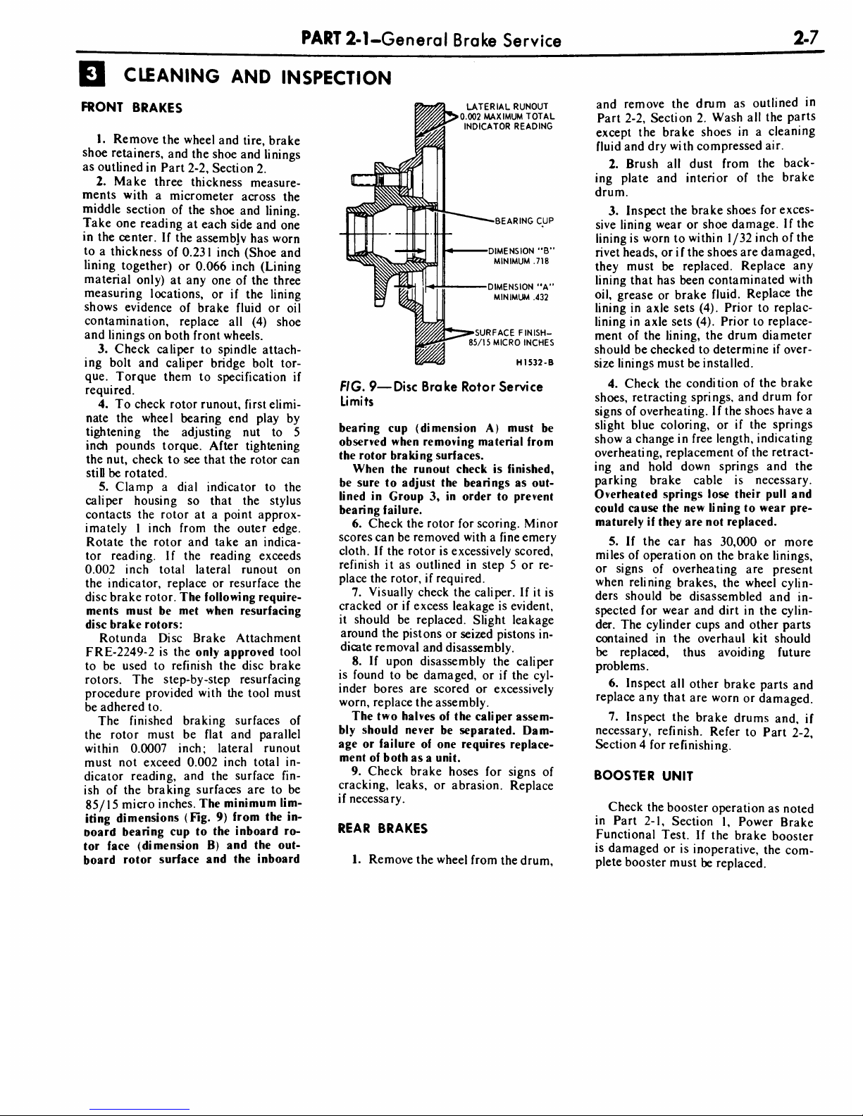
The
minimum
lim
iting
dimensions
(Fig.
9)
from
the
in-
noard
bearing
cup
to
the
inboard
ro
tor
face
(dimension
B)
and
the
out
board
rotor
surface
and
the
inboard
LATER1AL
RUNOUT
0.002
MAXIMUM
TOTAL
INDICATOR
READING
BEARING
CUP
DIMENSION
"B1
MINIMUM
.718
DIMENSION
"A'
MINIMUM
.432
SURFACE
FINISH-
85/15
MICRO
INCHES
H1532-B
FIG.
9
Disc
Brake
Rotor
Service
Limits
bearing
cup
(dimension
A)
must
be
observed
when
removing
material
from
the
rotor
braking
surfaces.
When
the
runout
check
is
finished,
be
sure
to
adjust
the
bearings
as
out
lined
in
Group
3,
in
order
to
prevent
bearing
failure.
6.
Check
the
rotor
for
scoring.
Minor
scores
can
be
removed with
a
fine
emery
cloth.
If
the
rotor
is
excessively
scored,
refinish
it
as
outlined
in
step
5
or
re
place
the
rotor,
if
required.
7.
Visually
check
the
caliper.
If
it
is
cracked orifexcess
leakage
is
evident,
it
should
be
replaced.
Slight
leakage
around
the
pistons
or
seized
pistons
in
dicate
removal
and
disassembly.
8.
If
upon
disassembly
the
caliper
is
found
to
be
damaged,
or
if
the
cyl
inder
bores
are
scored
or
excessively
worn,
replace
the
assembly.
The
two
halves
of
the
caliper
assem
bly
should
never
be
separated.
Dam
age
or
failure
of
one
requires
replace
ment
of
both
as
a
unit.
9.
Check
brake
hoses
for
signs
of
cracking,
leaks,
or
abrasion.
Replace
if
necessary.
REAR
BRAKES
1.
Remove
the
wheel
from
the
drum,
and
remove
the
drum
as
outlined
in
Part
2-2,
Section
2.
Wash
all
the
parts
except
the
brake
shoes
in
a
cleaning
fluid
and
dry
with
compressed
air.
2.
Brush
all
dust
from
the
back
ing
plate
and
interior
of
the
brake
drum.
3.
Inspect
the
brake
shoes
for
exces
sive
lining
wear or
shoe
damage.
If
the
lining
is
worn
to
within
1/32
inch
of
the
rivet
heads,
or
if
the
shoes
are
damaged,
they
must
be
replaced.
Replace
any
lining
that
has
been
contaminated
with
oil,
grease
or
brake
fluid.
Replace
the
lining
in
axle
sets
(4).
Prior
to
replac-
lining
in
axle
sets
(4).
Prior
to
replace
ment
of
the
lining,
the
drum
diameter
should
be
checked
to
determine
if
over
size
linings
must
be
installed.
4.
Check
the
condition
of
the
brake
shoes,
retracting
springs,
and
drum
for
signs
of
overheating.
If
the
shoes
have
a
slight
blue
coloring,
or
if
the
springs
show
a
change
in
free
length,
indicating
overheating,
replacement
of
the
retract
ing
and
hold
down
springs
and
the
parking
brake
cable
is
necessary.
Overheated
springs
lose
their
pull
and
could
cause
the
new
lining
to
wear
pre
maturely
if
they
are
not
replaced.
5.
If
the
car
has
30,000
or
more
miles
of
operation
on
the
brake
linings,
or
signs
of
overheating
are
present
when
relining
brakes,
the
wheel
cylin
ders
should
be
disassembled
and
in
spected
for
wear and
dirt
in
the
cylin
der.
The
cylinder
cups
and
other
parts
contained
in
the
overhaul
kit
should
be
replaced,
thus
avoiding
future
problems.
6.
Inspect
all
other
brake
parts
and
replace
any
that
are
worn
or
damaged.
7.
Inspect
the
brake
drums
and,
if
necessary,
refinish.
Refer
to
Part
2-2,
Section
4
for
refinishing.
BOOSTER
UNIT
Check
the
booster
operation
as
noted
in
Part
2-1,
Section
1,
Power
Brake
Functional
Test.
If
the
brake
booster
is
damaged
or
is
inoperative,
the
com
plete
booster
must
be
replaced.
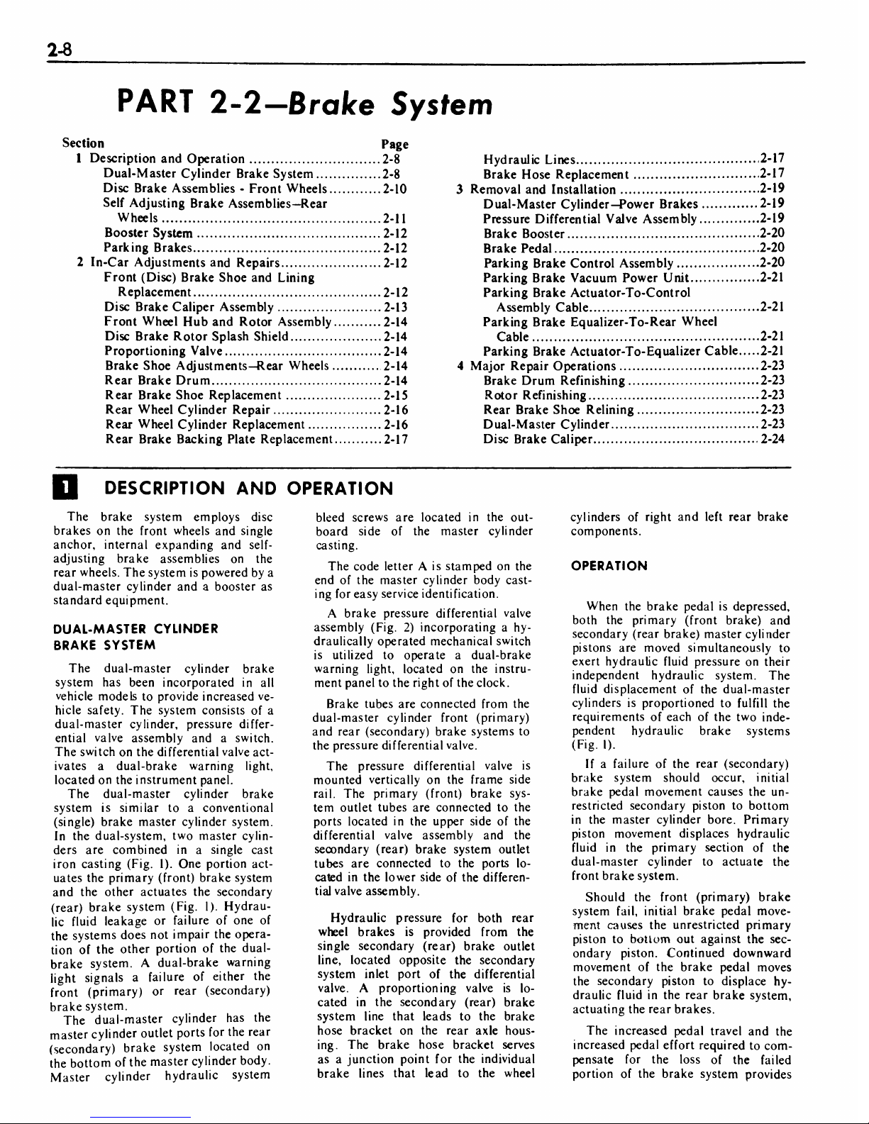
2-8
PART
2-2-Brake
System
Section
Page
1
Description
and
Operation
2-8
Dual-Master
Cylinder
Brake
System
2-8
Disc
Brake
Assemblies
-
Front
Wheels
2-10
Self
Adjusting
Brake
Assemblies
Rear
Wheels
2-11
Booster
System
2-12
Parking
Brakes
2-12
2
In-Car
Adjustments
and
Repairs
2-12
Front
(Disc)
Brake
Shoe
and
Lining
Replacement
2-12
Disc
Brake
Caliper
Assembly
2-13
Front
Wheel
Hub
and
Rotor
Assembly
2-14
Disc
Brake
Rotor
Splash
Shield
2-14
Proportioning
Valve
2-14
Brake
Shoe
Adjustments
Rear
Wheels
2-14
Rear
Brake
Drum
2-14
Rear
Brake
Shoe
Replacement
2-15
Rear
Wheel
Cylinder
Repair
2-16
Rear
Wheel
Cylinder
Replacement
2-16
Rear
Brake
Backing
Plate
Replacement
2-17
Hydraulic
Lines
2-17
Brake
Hose
Replacement
2-17
Removal
and
Installation
2-19
Dual-Master
Cylinder
Power Brakes
2-19
Pressure
Differential
Valve
Assembly
2-19
Brake
Booster
2-20
Brake
Pedal
2-20
Parking
Brake
Control
Assembly
2-20
Parking
Brake
Vacuum
Power
Unit
2-21
Parking
Brake
Actuator-To-Control
Assembly
Cable
2-2
1
Parking
Brake
Equalizer-To-Rear
Wheel
Cable
2-21
Parking
Brake
Actuator-To-Equalizer
Cable
2-21
Major
Repair
Operations
2-23
Brake
Drum
Refinishing
2-23
Rotor
Refinishing
2-23
Rear
Brake
Shoe
Relining
2-23
Dual-Master
Cylinder
2-23
Disc
Brake
Caliper
2-24
DESCRIPTION
AND
OPERATION
The
brake
system
employs
disc
brakes
on
the
front
wheels
and
single
anchor,
internal
expanding
and
self-
adjusting
brake
assemblies
on
the
rear
wheels.
The
system
is
powered
by
a
dual-master
cylinder
and
a
booster
as
standard
equipment.
DUAL-MASTER
CYLINDER
BRAKE
SYSTEM
The
dual-master
cylinder
brake
system
has
been
incorporated
in
all
vehicle
models
to
provide
increased
ve
hicle
safety.
The
system
consists
of
a
dual-master
cylinder,
pressure
differ
ential
valve
assembly
and
a
switch.
The
switch
on
the
differential
valve
act
ivates
a
dual-brake
warning
light,
located
on
the
instrument
panel.
The
dual-master
cylinder
brake
system
is
similar
to
a
conventional
(single)
brake
master
cylinder
system.
In
the
dual-system,
two
master
cylin
ders
are
combined
in
a single
cast
iron
casting
(Fig.
1).
One
portion
act
uates
the
primary
(front)
brake
system
and
the
other
actuates
the
secondary
(rear)
brake
system
(Fig.
1).
Hydrau
lic
fluid
leakage
or
failure
of
one
of
the
systems
does
not
impair
the
opera
tion
of
the
other
portion
of
the
dual-
brake
system.
A
dual-brake
warning
light
signals
a
failure
of
either
the
front
(primary)
or
rear
(secondary)
brake
system.
The
dual-master
cylinder
has
the
master
cylinder
outlet
ports
for
the
rear
(secondary)
brake
system
located
on
the
bottom
of
the
master
cylinder
body.
Master
cylinder
hydraulic
system
bleed
screws
are
located
in
the
out
board
side
of
the
master
cylinder
casting.
The
code
letter
A
is
stamped
on
the
end
of
the
master
cylinder
body
cast
ing
for
easy
service
identification.
A
brake
pressure
differential
valve
assembly
(Fig.
2)
incorporating
a
hy-
draulically
operated
mechanical
switch
is
utilized
to
operate
a
dual-brake
warning
light,
located
on
the
instru
ment
panel
to
the
right
of
the
clock.
Brake
tubes
are
connected
from
the
dual-master
cylinder
front
(primary)
and
rear
(secondary)
brake
systems
to
the
pressure
differential
valve.
The
pressure
differential
valve
is
mounted
vertically
on
the
frame
side
rail.
The
primary
(front)
brake
sys
tem
outlet
tubes
are
connected
to
the
ports
located
in
the
upper
side
of
the
differential
valve
assembly
and
the
secondary
(rear)
brake
system
outlet
tubes
are
connected
to
the
ports
lo
cated
in
the
lower
side
of
the
differen
tial
valve
assembly.
Hydraulic
pressure
for
both
rear
wheel
brakes
is
provided
from
the
single
secondary
(rear)
brake
outlet
line,
located
opposite
the
secondary
system
inlet
port
of
the
differential
valve.
A
proportioning
valve
is
lo
cated
in
the
secondary
(rear)
brake
system
line
that
leads
to
the
brake
hose
bracket
on
the
rear
axle
hous
ing.
The
brake
hose
bracket
serves
as
a
junction
point
for
the
individual
brake
lines
that
lead
to
the
wheel
cylinders
of
right
and
left
rear
brake
components.
OPERATION
When
the
brake
pedal
is
depressed,
both
the
primary
(front
brake)
and
secondary
(rear
brake)
master
cylinder
pistons
are
moved
simultaneously
to
exert
hydraulic
fluid
pressure
on
their
independent
hydraulic
system.
The
fluid
displacement
of
the
dual-master
cylinders
is
proportioned
to
fulfill
the
requirements
of
each
of
the
two
inde
pendent
hydraulic
brake
systems
(Fig.
I).
If
a
failure
of
the
rear
(secondary)
brake
system
should
occur,
initial
brake
pedal
movement
causes
the
un
restricted
secondary
piston
to
bottom
in
the
master cylinder
bore.
Primary
piston
movement
displaces
hydraulic
fluid
in
the
primary
section
of
the
dual-master
cylinder
to
actuate
the
front
brake
system.
Should
the
front
(primary)
brake
system
fail,
initial
brake
pedal
move
ment
causes
the
unrestricted
primary
piston
to
botlom
out
against
the
sec
ondary
piston.
Continued
downward
movement
of
the
brake
pedal
moves
the
secondary
piston
to
displace
hy
draulic
fluid
in
the
rear
brake
system,
actuating
the
rear
brakes.
The
increased
pedal
travel
and
the
increased
pedal
effort
required
to
com
pensate
for
the
loss
of
the
failed
portion
of
the
brake
system
provides
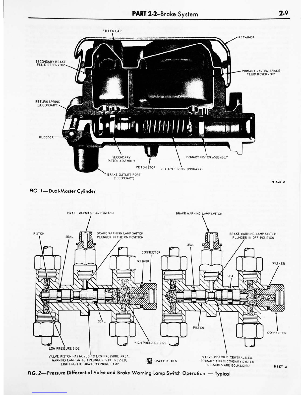
PART
2-2-Brake
System
2-9
FILLER
CAP
SECONDARY
BRAKE
FLUID
RESERVOIR
RETURN
SPRING
(SECONDARY)
BLEEDER
RETAINER
PRIMARY
SYSTEM
BRAKE
FLUID
RESERVOIR
RETURN
SPRING
(PRIMARY)
BRAKE
OUTLET
PORT
(SECONDARY)
FIG.
1
Dual-Master
Cylinder
H1526-A
BRAKE
WARNING
LAMP
SWITCH
BRAKE
WARNING
LAMP
SWITCH
PISTON
BRAKE
WARNING
LAMP
SWITCH
PLUNGER
IN
OFF
POSITION
WASHER
CONNECTOR
LOW
PRESSURE
SIDE
VALVE
PISTON
HAS
MOVED
TO
LOW
PRESSURE
AREA.
WARNING
LAMP
SWITCH
PLUNGER
IS
DEPRESSED,
LIGHTING
THE
BRAKE
WARNING
LAMP
BRAKE
FLUID
VALVE
PISTON
IS
CENTRALIZED.
PRIMARY
AND
SECONDARY
SYSTEM
PRESSURES
ARE
EQUALIZED
H1471-A
FIG.
2
Pressure
Differential
Valve
and
Brake
Warning
Lamp
Switch
Operation
Typical
 Loading...