

Ford Thunderbird 1966 Shop Manual
1966
FORD
SHOP
MA
Copyright © 2009, Forel Publishing Company, LLC, Woodbridge, Virginia
All Rights Reserved. No part of this book may be used or reproduced in any manner whatsoever
without written permission of Forel Publishing Company, LLC. For information write to Forel
Publishing Company, LLC, 3999 Peregrine Ridge Ct., Woodbridge, VA 22192
1966 Ford Thunderbird Shop Manual
EAN: 978-1-60371-016-9
ISBN: 1-60371-016-7
Forel Publishing Company, LLC
3999 Peregrine Ridge Ct.
Woodbridge, VA 22192
Email address: webmaster@ForelPublishing.com
Website: http://www.ForelPublishing.com
This publication contains material that is reproduced and distributed under a license from Ford
Motor Company. No further reproduction or distribution of the Ford Motor Company material is
allowed without the express written permission of Ford Motor Company.
NNoottee ffrroomm tthhee EEddiittoorr
This product was created from the original Ford Motor Company’s publication. Every effort has
been made to use the original scanned images, however, due to the condition of the material;
some pages have been modified to remove imperfections.
Although every effort was made to ensure the accuracy of this book, no representations or
warranties of any kind are made concerning the accuracy, completeness or suitability of the
information, either expressed or implied. As a result, the information contained within this book
should be used as general information only. The author and Forel Publishing Company, LLC
shall have neither liability nor responsibility to any person or entity with respect to any loss or
damage caused, or alleged to be caused, directly or indirectly by the information contained in
this book. Further, the publisher and author are not engaged in rendering legal or other
professional services. If legal, mechanical, electrical, or other expert assistance is required, the
services of a competent professional should be sought.
Disclaimer
GROUP
INDEX
Imrnf^k
mI"**
m^
m^ll
pffllik
liwik
^J5^)SERVICE
PUBLICATIONS
FIRST
PRINTING
AUGUST,
1985
1965
FORD
MOTOR
COMPANY.
DEARBORN,
MICHIGAN
Reproduced
under
License
#
5008
from
Ford
Motor
Company
-
May
2000
CHICLE
IDENTIFICATION
DRIVE
SHAFT
AND
CLUTCH
MANUAL
SHIFT
TRANSMISSION
(Not
Applicable)
AUTOMATIC
TRANSMISSION
mH
ENGINE
.
\WL%\mjB/nKmKKMmmmmMm^
mm.
a
m^^simWimK^aBMkm^iwm^am^mm^mwm^Mmwm^m^mwKM
IGNITION
SYSTEM
BB
FUEL
SYSTEM
ITS1
121
1^
COOLING
SYSTEM
MM
EXHAUST
SYSTEM
J^Mj
CHARGING
SYSTEM
STARTING
SYSTEM
UGHTJNG
SYSTEM,
HORNS
AND
INSTRUMENTS
VENTILATING,
HEATING
AND
ACCESSORIES
BODY,
DOORS
AND
WINDOWS
TRIM,
SEATS
AND
CONVERTIBLE
TOP
fTTI
haWaaal
MAINTENANCE
SCHEDULE
MAINTENANCE
OPERATIONS
LUBRICATION
CHARTS
AND
SPECIFICATIONS
SCHEMATICS
20
SPECIFICATIONS
AND
SPECIAL
SERVICE
TOOLS
AT
END
OF
EACH
GROUP

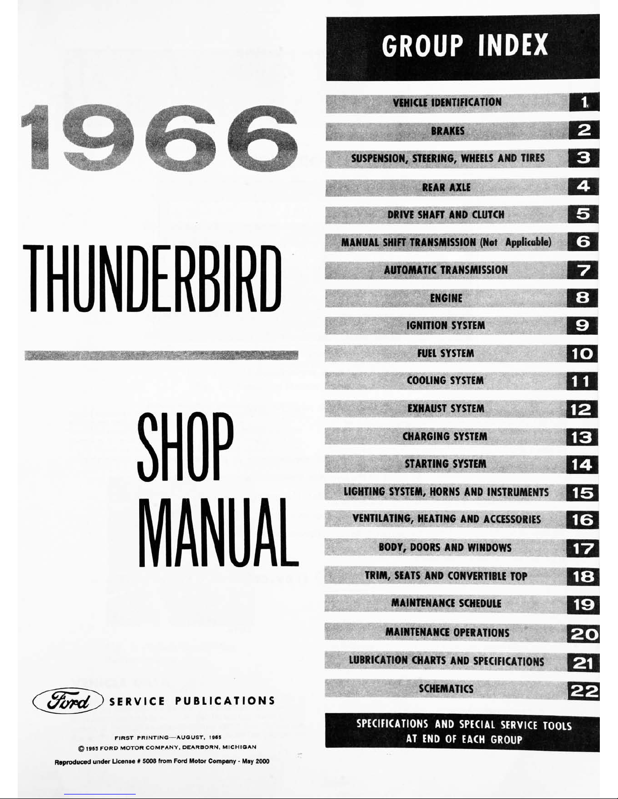
FOREWORD
This
shop
manual
provides
the
Service
Technician
with
complete
information
for
the
proper
servicing
of
the
1966
Thunderbird
The
information
is
grouped
according
to the
type
of
work
being
performed,
such
as
diagnosis
and
testing,
frequently
performed
adjustments
and
repairs,
in-vehicle
adjustments,
overhaul,
etc.
Specifications
and
recom
mended special
tools
are
included.
Refer
to
the
opposite
page
for
important
vehicle
identi
fication
data.
The
descriptions
and
specifications
in
this
manual
were
in
effect
at
the
time
this
manual
was
approved
for
print
ing.
The
Ford
Motor
Company
reserves
the
right
to
discontinue
models
at
any
time,
or
change
specifications
or
design,
without
notice
and
without
incurring
obligation,
^d
SERVICE
PUBLICATIONS
1-1
\/ri
iif*i
p
IDENTIFICATION
GROUP
1
EXTERIOR
PAINT
COLOR
(WHITE)
BODY
STYLE
\
(2
DOOR
HARDTOP)
\
DATE
CODE
(26TH
DAY
AUGUST)
INTERIOR
TRIM
SILVER
MINK
DETROIT
DISTRICT
AXLE
RATIO
CODE
(3.00:1
AXLE
RATIO)
TRANSMISSION
CODE
(C6
DUAL
RANGE
AUTOMATIC)
BODY//
COLORJ
TRIIVUJ
DATE//
dso/
U
AXLE
ILTRANS
63A
M.'
21
'
26H
33
N
N
j
VEHICLE
WARRANTY
NUMBER
\\OT
\pR
TITLE
Q
>N
PURPOSES
.
,
IEWS
MANUFACTURED
UNDER
UNITED
STATES
D
CTOEI&N
PATENTS
AND
PATENT
APPLICATIONS
A
P\\ODl\VT
OF
lt^^
y
MOTOR
COMPANY
MODEL
YEAR
(1966)
ASSEMBLY
PLANT
(WIXOM)
-\-
CONSECUTIVE UNIT
NUMBER
^ENGINE
CODE
(8
CYL.
390
CID
ENGINE)
BODY
SERIAL
CODE
(2-DOOR
HARDTOP)
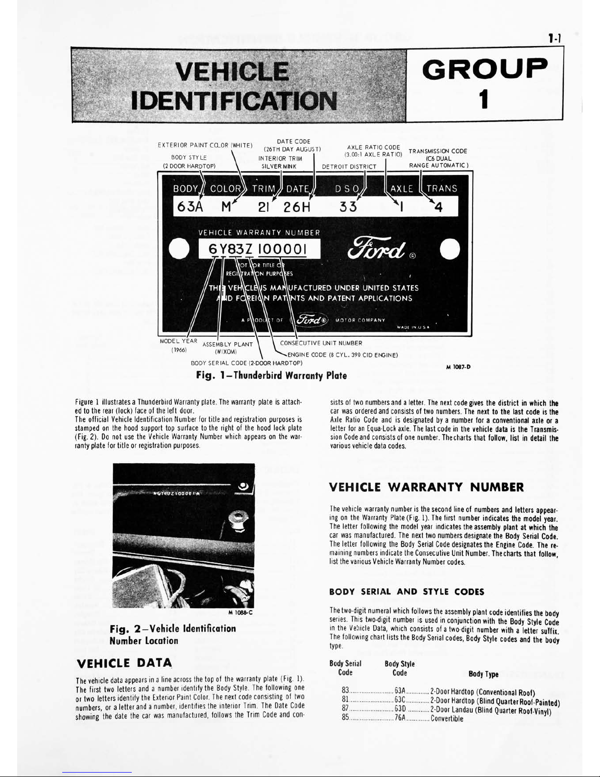
Fig.
1
-Thunderbird
Warranty
Plate
M
1087-D
Figure1illustrates
a
Thunderbird
Warranty
plate.
The
warranty
plate
is
attach
ed
to
the
rear
(lock)
face
of
the
left
door.
The
official
Vehicle
Identification
Number
for
title
and
registration
purposes
is
stamped
on
the
hood
support
top
surface
to
the
right
of
the
hood
lock
plate
(Fig. 2).
Do
not
use
the
Vehicle
Warranty
Number
which
appears
on
the
war
ranty
plate
for
title
or
registration
purposes.
sists
of
two
numbers
and
a
letter.
The
next
code
gives
the
district
in
which
the
car
was
ordered
and
consists
of
two
numbers.
The
next
to
the
last
code
is
the
Axle
Ratio Code
and
is
designated
by
a
number
for
a
conventional
axle
or
a
letter
for
an
Equa-Lock
axle.
The
last
code
in
the
vehicle
data
is
the
Transmis
sion
Code
and
consists
of
one
number.
The
charts
that
follow,
list
in
detail
the
various
vehicle
data
codes.
M
1088-C
Fig.
2
-Vehicle
Identification
Number
Location
VEHICLE
DATA
The
vehicle
data
appears
inaline
across
the
top
of
the
warranty
plate
(Fig.
1).
The
first
two
letters
and
a
number
identify
the
Body
Style.
The
following
one
or
two
letters
identify
the
Exterior
Paint
Color.
The
next
code
consisting
of
two
numbers,
or
a
letter
and
a
number,
identifies
the
interior
Trim.
The
Date
Code
showing
the
date
the
car
was
manufactured,
follows
the
Trim
Code
and
con-
VEHICLE
WARRANTY
NUMBER
The
vehicle
warranty
number
is
the
second
line
of
numbers
and
letters
appear
ing
on
the
Warranty
Plate
(Fig.
1).
The
first
number
indicates
the
model
year.
The
letter
following
the
model
year
indicates
the
assembly
plant
at
which
the
car
was
manufactured.
The
next
two
numbers
designate
the
Body
Serial
Code.
The
letter
following
the
Body
Serial
Code
designates
the
Engine
Code.
The
re
maining
numbers
indicate
the
Consecutive
Unit
Number.
Thecharts
that
follow,
list
the
various
Vehicle
Warranty
Number
codes.
BODY
SERIAL
AND
STYLE
CODES
The
two-digit
numeral
which
follows
the
assembly
plant
code
identifies
the
body
series.
This
two-digit
number
is
used
in
conjunction
with
the
Body
Style
Code
in
the
Vehicle
Data,
which
consists
of
a
two-digit
number
with
a
letter
suffix
The
following
chart
lists
the
Body
Serial
codes,
Body
Style
codes
and
the
body
type.
Body
Serial
Body
Style
Code
Code
Body
Type
83
63A
2-Door
Hardtop
(Conventional
Roof)
81
63C
2-Door
Hardtop
(Blind
Quarter
Roof-Painted)
87
63D
2-Door
Landau
(Blind
Quarter
Roof-Vinvh
85
76A
Convertible
1}
12
GROUP
1-
VEHICLE
IDENTIFICATION
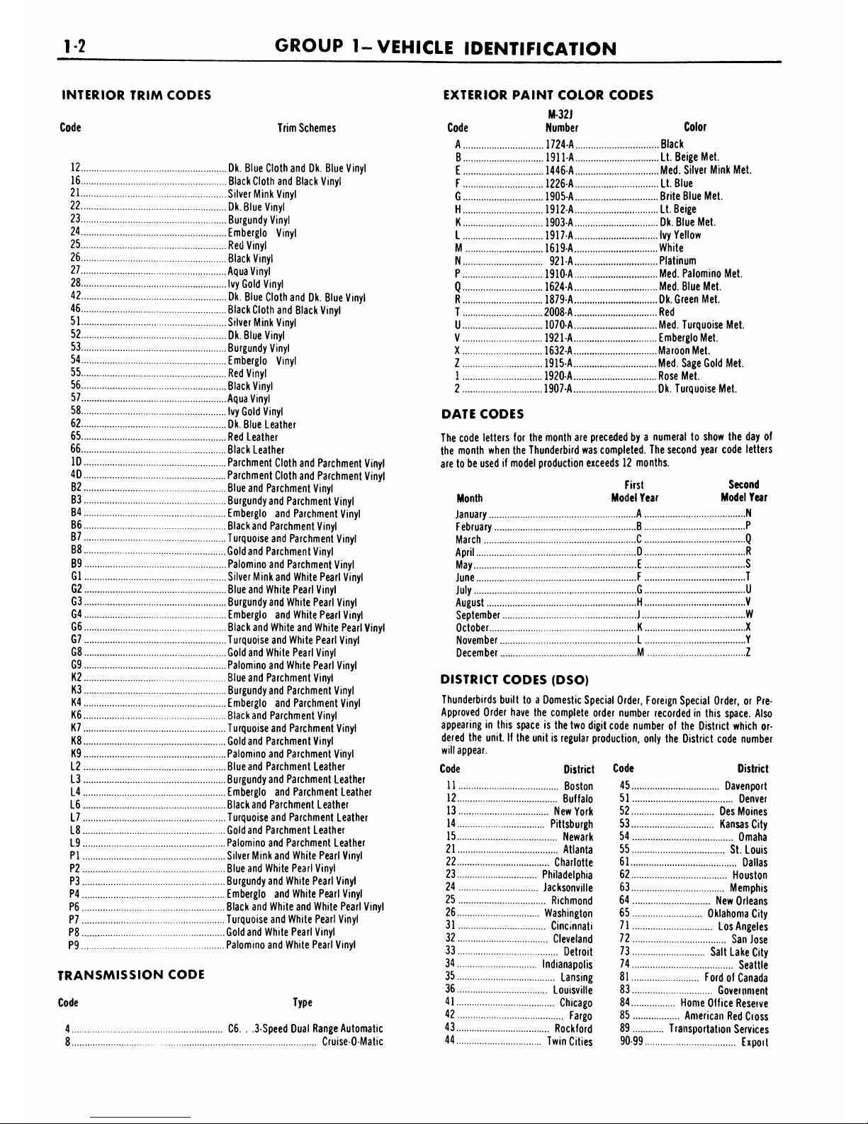
INTERIOR TRIM
CODES
Code
Trim
Schemes
12
Dk.
Blue
Cloth
and
Dk.
Blue
Vinyl
16
Black
Cloth
and
Black
Vinyl
21
Silver
Mink
Vinyl
22
Dk.
Blue
Vinyl
23
Burgundy
Vinyl
24
Emberglo
Vinyl
25
Red
Vinyl
26
Black
Vinyl
27
Aqua
Vinyl
28
Ivy
Gold
Vinyl
42
Dk.
Blue
Cloth
and
Dk.
Blue
Vinyl
46
Black
Cloth
and
Black
Vinyl
51
Silver
Mink
Vinyl
52
Dk.
Blue
Vinyl
53
Burgundy
Vinyl
54
Emberglo
Vinyl
55
Red
Vinyl
56
Black
Vinyl
57
Aqua
Vinyl
58
Ivy
Gold
Vinyl
62
Dk.
Blue
Leather
65
Red
Leather
66
Black
Leather
ID
Parchment
Cloth
and
Parchment
Vinyl
40
Parchment
Cloth
and
Parchment
Vinyl
B2
Blue
and
Parchment
Vinyl
B3
Burgundy
and
Parchment
Vinyl
B4
Emberglo
and
Parchment
Vinyl
B6
Blackand
Parchment
Vinyl
B7
Turquoise
and
Parchment
Vinyl
B8
Gold
and
Parchment
Vinyl
B9
Palomino
and
Parchment
Vinyl
Gl
Silver
Mink
and
White
Pearl
Vinyl
G2
Blue
and
White
Pearl
Vinyl
G3
Burgundy
and
White
Pearl
Vinyl
G4
Emberglo
and
White
Pearl
Vinyl
G6
Black
and
White
and
White
Pearl
Vinyl
G7
Turquoise
and
White
Pearl
Vinyl
G8
Gold
and
White
Pearl
Vinyl
G9
Palomino
and
White
Pearl
Vinyl
K2
Blue
and
Parchment
Vinyl
K3
Burgundy
and
Parchment
Vinyl
K4
Emberglo
and
Parchment
Vinyl
K6
Blackand
Parchment
Vinyl
K7
Turquoise
and
Parchment
Vinyl
K8
Gold
and
Parchment
Vinyl
K9
Palomino
and
Parchment
Vinyl
L2
Blue
and
Parchment
Leather
L3
Burgundy
and
Parchment
Leather
L4
Emberglo
and
Parchment
Leather
L6
Blackand
Parchment Leather
L7
Turquoise
and
Parchment
Leather
L8
Gold
and
Parchment
Leather
L9
Palomino
and
Parchment
Leather
PI
Silver
Mink
and
White
Pearl
Vinyl
P2
Blue
and
White
Pearl
Vinyl
P3
Burgundy
and
White
Pearl
Vinyl
P4 Emberglo
and
White
Pearl
Vinyl
P6
Black
and
White
and
White
Pearl
Vinyl
P7
Turquoise
and
White
Pearl
Vinyl
P8
Gold
and
White
Pearl
Vinyl
P9
Palomino
and
White
Pearl
Vinyl
TRANSMISSION
CODE
Code
4
EXTERIOR
PAINT
COLOR
CODES
M-32J
Code
Number
Color
A
1724-A
Black
B
1911
A
Lt.
Beige
Met.
E
1446-A
Med.
Silver
Mink
Met.
F
1226-A
Lt.
Blue
G
1905-A
Brite
Blue
Met.
H
1912-A
Lt.
Beige
K
1903-A
Dk.
Blue
Met.
L
1917-A
Ivy
Yellow
M
1619-A
White
N
921-A
Platinum
P
1910-A
Med.
Palomino
Met.
Q
1624-A
Med.
Blue
Met.
R
1879-A
Dk.
Green Met.
T
2008-A Red
U
1070-A
Med.
Turquoise
Met.
V
1921
A
Emberglo
Met.
X
1632-A
Maroon
Met.
Z
1915-A
Med.
Sage
Gold
Met.
1
1920-A
Rose
Met.
2
1907-A
Dk.
Turquoise
Met.
DATE
CODES
The
code
letters
for
the
month
are preceded
by
a
numeral
to
show
the
day
of
the
month
when
the
Thunderbird
was
completed.
The
second
year code
letters
are
to
be
used
if
model
production
exceeds
12
months.
First
Second
Month
Model
Year
Model
Year
January
A
N
February
B
P
March
C
Q
April
D
R
May
E
S
June
F
T
July
G
U
August
H
V
September
J
W
October
K
X
November
L
Y
December
M
Z
DISTRICT
CODES
(DSO)
Thunderbirds
built
to
a
Domestic Special
Order,
Foreign
Special
Order,
or
Pre-
Approved
Order
have
the
complete
order
number
recorded
in
this
space.
Also
appearing
in
this
space
is
the
two
digit
code
number
of
the
District
which
or
dered the
unit.
If
the
unit
is
regular
production,
only
the
District
code
number
will
appear.
Code
District
Code
District
C6.
Type
3
Speed
Dual
Range
Automatic
Cruise-O-Matic
11
Boston
12
Buffalo
13
New
York
14
Pittsburgh
15
Newark
21
Atlanta
22
Charlotte
23
Philadelphia
24
Jacksonville
25
Richmond
26
Washington
31
Cincinnati
32
Cleveland
33
Detroit
34
Indianapolis
35
Lansing
36
Louisville
41
Chicago
42
Fargo
43
Rockford
44
Twin
Cities
45
Davenport
51
Denver
52
Des
Moines
53
Kansas
City
54
Omaha
55
St.
Louis
61
Dallas
62
Houston
63
Memphis
64
New
Orleans
65
Oklahoma
City
71
Los
Angeles
72
San
Jose
73
Salt
Lake
City
74
Seattle
81
Ford
of
Canada
83
Government
84
Home
Office
Reseive
85
American
Red
Cioss
89
Transportation
Services
90-99
Expoit

PART
1-VEHICLE
IDENTIFICATION
1-3
REAR
AXLE
RATIO
CODE
Code
Ratio
1
3.00:1
3
3.20:1
6
2.80:1
ENGINE
CODES
Code
Type
Z
8
Cylinder
390
Cubic
Inch
(4
barrel)
Q
8
Cylinder
428
Cubic
Inch
(4
barrel)
CONSECUTIVE
UNIT
NUMBER
The
assembly
plant,
with
each
model
year,
begins
with
consecutive
unit
num
ber
100001
and
continues
on
for
each
unit
built.
ASSEMBLY
PLANT
CODES
Code
Letter
Assembly
Plant
A
Atlanta
B
Oakville
Passenger
C
Ontario
Truck
D
Dallas
E
Mahwah
G
Chicago
H
Lorain
J
Los
Angeles
K
Kansas
City
L
Michigan
Truck
MODEL
YEAR
The
number
6
designates
1966
Code
Letter
Assembly
Plant
N
Norfolk
p
Twin
Cities
R
San
Jose
S
Pilot
Plant
T
Metuchen
U
Louisville
W
Wayne
Y
Wixom
Z
St.
Louis
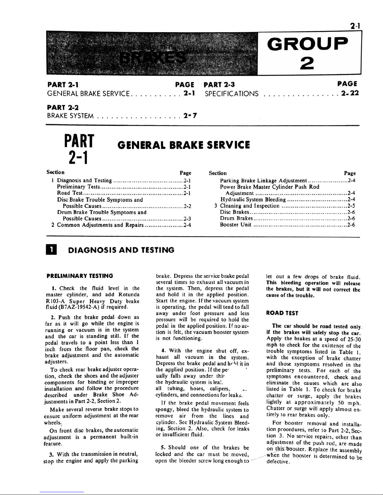
2-1
GROUP
PART
2-1
GENERAL
BRAKE
SERVICE
PART
2-2
BRAKE
SYSTEM
PAGE
PART
2-3
. .
2-1
SPECIFICATIONS
PAGE
.
2.22
2-7
PART
2-1
GENERAL
BRAKE
SERVICE
Section
Page
1
Diagnosis
and
Testing
2-1
Preliminary
Tests
2-1
Road
Test
2-1
Disc
Brake
Trouble
Symptoms
and
Possible
Causes
2-2
Drum
Brake
Trouble
Symptoms
and
Possible
Causes
2-3
2
Common
Adjustments
and
Repairs
2-4
Section
Page
Parking
Brake
Linkage
Adjustment
2-4
Power
Brake
Master
Cylinder
Push
Rod
Adjustment
2-4
Hydraulic
System
Bleeding
2-4
3
Cleaning
and
Inspection
2-5
Disc
Brakes 2-6
Drum
Brakes
2-6
Booster
Unit
2-6
DIAGNOSIS
AND
TESTING
PRELIMINARY
TESTING
1.
Check
the
fluid
level
in
the
master
cylinder,
and
add
Rotunda
R103-A
Super
Heavy
Duty
brake
fluid
(B7AZ-19542-A)
if
required.
2.
Push
the
brake
pedal
down
as
far
as
it
will
go
while
the
engine
is
running
or
vacuum
is
in
the
system
and
the
car
is
standing
still.
If
the
pedal
travels
to
a
point
less
than
1
inch
from
the
floor
pan,
check
the
brake
adjustment
and
the
automatic
adjusters.
To
check
rear
brake
adjuster
opera
tion,
check
the
shoes
and
the
adjuster
components
for
binding
or
improper
installation
and
follow
the
procedure
described
under
Brake
Shoe
Ad
justments
in
Part
2-2,
Section
2.
Make
several
reverse
brake
stops
to
ensure
uniform
adjustment
at
the
rear
wheels.
On
front
disc
brakes,
the
automatic
adjustment
is
a
permanent
built-in
feature.
3.
With
the
transmission
in
neutral,
stop
the
engine
and
apply
the
parking
brake.
Depress
the
service
brake
pedal
several
times
to
exhaust
all
vacuum
in
the
system.
Then,
depress
the
pedal
and
hold
it
in
the
applied
position.
Start
the
engine.
If
the
vacuum
system
is
operating,
the
pedal
will
tend
to
fall
away
under
foot
pressure
and
less
pressure
will
be
required
to
hold
the
pedal
in
the
applied
position.
If
no
ac
tion
is
felt,
the
vacuum
booster
system
is
not
functioning.
4.
With
the
engine
shut
off,
ex
haust
all
vacuum
in
the
system.
Depress
the
brake
pedal
and
hr'd
it
in
the
applied
position.
Ifthepc
ually
falls
away
under
thi?
the
hydraulic
system
is
lea!.
all
tubing,
hoses,
calipers,
cylinders,
and
connections
for
leaks.
If
the
brake
pedal
movement
feels
spongy,
bleed
the
hydraulic
system
to
remove
air
from
the
lines
and
cylinder.
See
Hydraulic
System
Bleed
ing,
Section
2.
Also,
check
for
leaks
or
insufficient
fluid.
5.
Should
one
of
the
brakes
be
locked
and
the
car
must
be
moved,
open
the
bleeder
screw
long
enough
to
let
out
a
few
drops
of
brake
fluid.
This
bleeding
operation
will
release
the
brakes,
but
it
will
not
correct
the
cause
of
the
trouble.
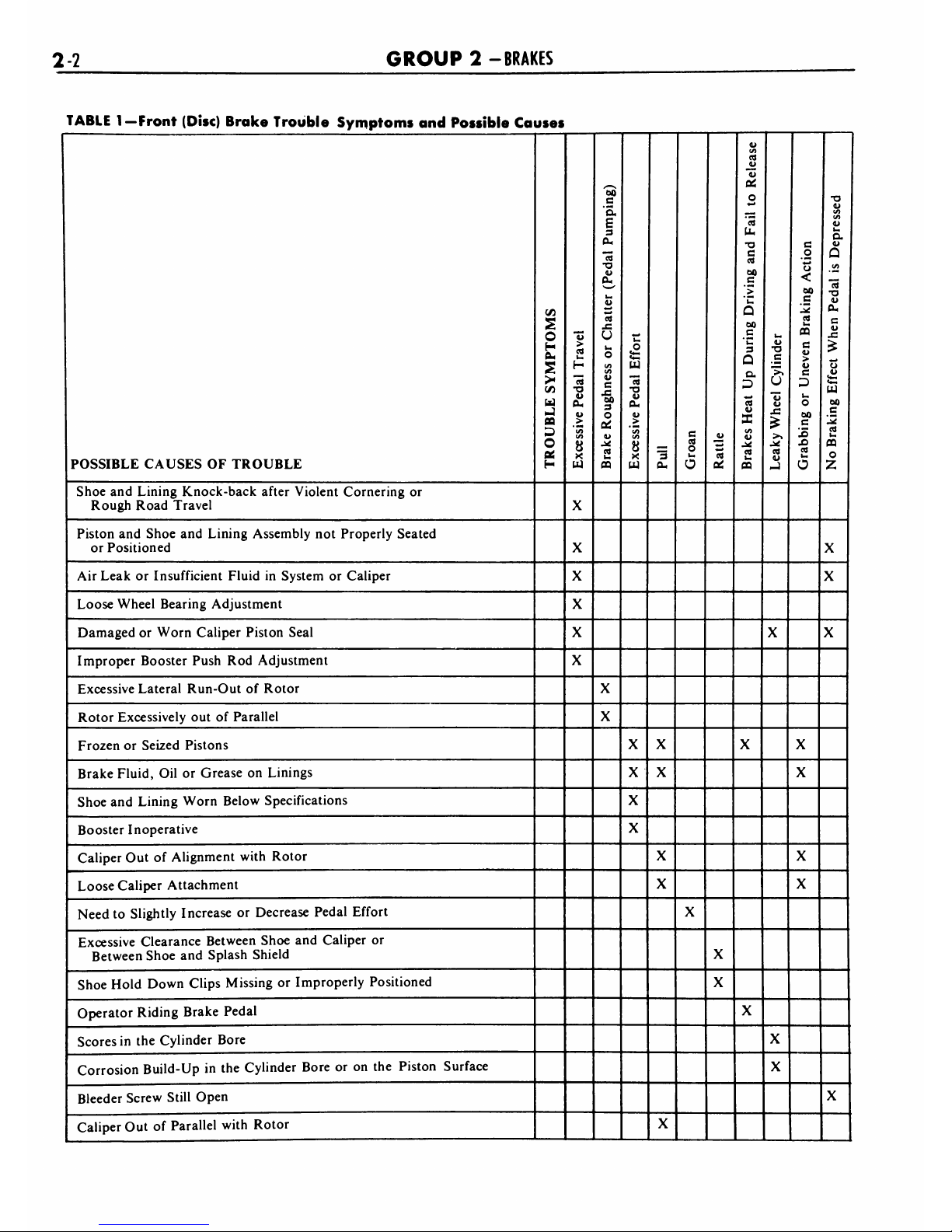
ROAD
TEST
The
car
should
be
road
tested
only
if
the
brakes
will
safely
stop
the
car.
Apply
the
brakes
at
a
speed
of
25-30
mph
to
check
for
the
existence
of
the
trouble
symptoms
listed
in
Table
1,
with
the
exception
of
brake
chatter
and
those
symptoms
resolved
in
the
preliminary
tests.
For
each
of
the
symptoms
encountered,
check
and
eliminate
the
causes
which
are
also
listed
in
Table
1.
To
check
for
brake
chatter
or
surge,
apply
the
brakes
lightly
at
approximately
50
mph.
Chatter
or
surge
will
apply
almost
en
tirely
to
rear
brakes
only.
For
booster
removal
and
installa
tion
procedures,
refer
to
Part
2-2,
Sec
tion
3.
No
service
repairs,
other
than
adjustment
of
the
push
rod,
are
made
onjhfcrfco-oster.
Replace
the
assembly
Avlien
the
booster
is
determined
to
be
defective.
2-2
GROUP
2
-BRAKES
TABLE
1
Front
(Disc)
Brake
Trouble
Symptoms
and
Possible
Causes
POSSIBLE
CAUSES
OF
TROUBLE
C/3
2
o
H
>
u
J
ca
S3
o
a.
H
>
CC
ha
H
"5
o
<l>
0-
V
>
</>
a
X
UJ
/S5
c
"S.
3
CU
"c5
T3
CL,
t-
U
ed
U
u
O
</>
</>
ii
c
_c
00
3
o
cQ
a
CO
u
o
<
.
<
UJ
"5
"O
V
da
>
8
X
UJ
3
a.
c
CQ
o
o
rt
CKJ
</>
CQ
JL>
*4>
a!
o
'3
U,
T3
C
d
oo
C
>
a
00
c
3
Q
o.
08
V
X
(/>
u
CQ
Urn
a>
c
">
U
13
u
>>
_:
CQ
-J
c
o
o
<
00
cQ
la)
OQ
c
>
u
c
ha
o
oo
c
15
X)
CQ
>
O
T3
u
(/>
</)
V
u
a
Q
(/>
"cQ
TJ
<1>
Oa
C
i>
Ua
00
c
12
CQ
Ua
CQ
O
Z
Shoe
and
Lining
Knock-back
after
Violent
Cornering
or
Rough
Road
Travel
X
Piston
and
Shoe
and
Lining
Assembly
not
Properly
Seated
or
Positioned
X
X
Air
Leak
or
Insufficient
FluidinSystem
or
Caliper
X
X
Loose
Wheel
Bearing
Adjustment
X
Damaged
or
Worn
Caliper
Piston
Seal
X
X X
Improper
Booster
Push
Rod
Adjustment
X
Excessive
Lateral
Run-Out
of
Rotor
X
Rotor
Excessively
out
of
Parallel
X
Frozen
or
Seized
Pistons
X X
X X
Brake
Fluid,
Oil
or
Grease
on
Linings
X X
X
Shoe
and
Lining
Worn
Below
Specifications
X
Booster
Inoperative
X
Caliper
Out
of
Alignment
with
Rotor
X
X
Loose
Caliper
Attachment
X
X
Need
to
Slightly
Increase
or
Decrease
Pedal
Effort
X
Excessive
Clearance
Between
Shoe
and
Caliper
or
Between
Shoe
and
Splash
Shield
X
Shoe
Hold
Down
Clips
Missing
or
Improperly
Positioned
X
Operator
Riding
Brake
Pedal
X
Scores
in
the
Cylinder
Bore
X
Corrosion
Build-Up
in
the
Cylinder
Bore
or
on
the
Piston
Surface
X
Bleeder
Screw
Still
Open
X
Caliper
Out
of
Parallel
with
Rotor
X
PART
2-1
-GENERAL
BRAKE
SERVICE
2-3
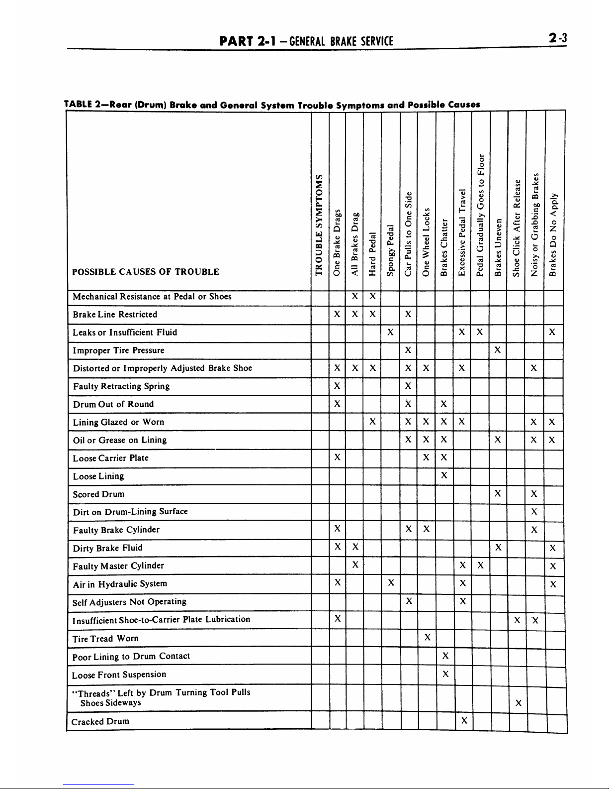
TABLE
2
Rear
(Drum)
Brake
and
General
System
Trouble
Symptoms
and
Possible
Causes
POSSIBLE
CAUSES
OF
TROUBLE
C/5
O
H
a.
>
u.
J
CC
O
ft.
H
00
ca
ha
Q
ha
CQ
c
O
00
C9
ha
Q
</i
u
rt
ha
ca
<
rt
-a
u
0-
T3
ha
X
T3
0-
>
00
c
o
a
on
u
.12
i/5
u
c
O
o
(/I
"3
ft.
ha
rt
u
10
.X
0
0
-J
"w
u
x:
c
0
u
u
<u
ca
ha
CQ
>
rt
ha
H
"rt
-0
u
Oa
cu
>
(/5
un
u
0
X
UJ
ha
0
u_
0
00
cu
0
0
>>
"rt
3
0
ca
ha
0
"rt
0
u
Oa
c
>
c
</)
rt
ha
CQ
(U
c/l
rt
s
ha
CU
<*-
<
0
0
(U
0
-n
00
00
u
-X
rt
CQ
00
c
IS
X)
ca
ha
0
ha
0
>-.
CO
'5
z
>>
a
a
<
0
z
0
a
I/)
u
J*
rt
ha
CC
Mechanical
Resistance
at
Pedal
or
Shoes
X
X
Brake
Line
Restricted
X X
X
X
Leaks
or
Insufficient
Fluid
X X
X
X
Improper
Tire
Pressure
X
X
Distorted
or
Improperly
Adjusted
Brake
Shoe
X X
X
X
X
X
X
Faulty
Retracting
Spring
X
X
Drum
Out
of
Round
X
X
X
Lining
Glazed
or
Worn
X X
X
X
X
X X
Oil
or
Grease
on
Lining
X
X
X
X
X
X
Loose
Carrier
Plate
X
X
X
Loose
Lining
X
Scored
Drum
X
X
Dirt
on
Drum-Lining
Surface
X
Faulty
Brake
Cylinder
X
X X
X
Dirty
Brake
Fluid
X
X
X
X
Faulty
Master
Cylinder
X
X
X
X
Air
in
Hydraulic
System
X
X
X
X
Self
Adjusters
Not
Operating
X
X
Insufficient
Shoe-to-Carrier
Plate
Lubrication
X
X
X
Tire
Tread
Worn
X
Poor
Lining
to
Drum
Contact
X
Loose
Front
Suspension
X
Threads"
Left
by
Drum
Turning
Tool
Pulls
Shoes
Sideways
X
Cracked
Drum
X
.

24
GROUP
2
-BRAKES
COMMON
ADJUSTMENTS
AND
REPAIRS
PARKING
BRAKE
LINKAGE
ADJUSTMENT
Check
the
parking
brake
cables
when
the
brakes
are
fully
released.
If
the
cables
are
loose,
adjust
them
as
follows:
1.
Fully
release
the
parking
brake
pedal
by
pushing
down
the
manual
release
lever.
2.
Raise
the
car.
3.
Adjust
the
equalizer
lever
against
the
cable
spring
on
the
pedal
cable
to
the
dimension
shown
in
Fig.
1.
4.
Loosen
the
adjusting
nut
on
the
equalizer
rod,
and
then
turn
the
lock
nut
in
front
of
the
equalizer
several
turns
forward.
5.
Depress
the
parking
brake
pedal
1
3/4
inches
from
its
normal
released
position.
6.
While
turning
the
rear
wheels
in
a
rearward
direction,
turn
the
ad
justing
nut
against
the
equalizer
until
a
moderate
drag
is
felt
(Fig.
1).
7.
When
the
cables
are
properly
adjusted,
tighten
the
lock
nut
against
the
equalizer.
8.
Release
the
parking
brake,
and
check
to
make
sure
that
the
brake
shoes
return
to
the
fully
released
position.
9.
Depress
the
parking
brake
pedal
two
inches.
Under
normal
conditions,
this
will
satisfactorily
hold
the
car.
10.
Release
the
parking
brake
again,
and
then
depress
the
pedal
1/2
inch.
The
brakes
should
not
drag
with
the
pedal
depressed
1/2
inch.
If
the
rear
brakes
do
not
fully
release,
check
the
cables
for
kinks
or
binds.
Free
the
cables
as
required.
MASTER
CYLINDER
PUSH
ROD
ADJUSTMENT
The
push
rod
is
designed
with
a
self-locking
adjustment
screw
to
provide
the
correct
relationship
between
the
booster
piston
and
the
master
cylinder
piston.
The
ad
justment
screw
is
set
to
the
correct
height
at
the
time
of
original
assembly
of
the
power
unit.
Under
normal
service
the
adjustment
screw
does
not
require
any
further
attention
providing
the
push
rod
assembly
re-
U-CLIP
CABLE
HOUSING
END
SPRING
SEAT
CABLE
SPRING
LEVER-TO-CABLE
ADJUSTING
NUT
EQUALIZER
ROD
EQUALIZER
LEVER
CABLES
TO
REAR
WHEELS
H1307-A
FIG.
1
Parking
Brake
Adjustments
mains
in
the
original
unit.
However,
when
a
new
push rod
is
used
or
the
push
rod
assembly
is
transferred to
another
unit,
the
distance
from
the
end
of
the
adjustment
screw
to
the
mounting
surface
of
the
booster
body
should
be
rechecked
either
with
a
micrometer
depth
gauge
to
a
dimen
sion
of
0.380
0.995
inch,
or
with
a
height
gauge
as
shown
in
Fig.2.The
details
for
making
a
height
gauge
are
given
in
Fig.
3.
ADJUSTMENT
SCREW
Push
Rod
Gauge
HI
086-
A
FIG.
2
-Push
Rod
Adjustment
#15
OR
#16
U.S.S.
GAUGE
SHEET
STEEL
2-7/8".
H1087-C
FIG.
3-Push
Rod
Gouge
Dimensions
To
adjust
the
push
rod,
hold
the
serrated
end
of
the
rod
with
cross-
milled
pliers
and
turn
the
adjustment
screw
in
to
shorten,
or
out
to
lengthen.
After
assembly
of
the
master
cylinder
to
the
power
section,
the
pis
ton
cup
in
the
hydraulic
cylinder
should
just
clear
the
compensating
port
hole
when
the
unit
is
in
the
fully
released
position.
This
can
be
checked
by
placing
a
few
drops
of
brake
fluid
over
the
compensating
port
and
ap
plying
light
air
pressure
to
the
output
port
of
the
master
cylinder.
If
air
bub
bles
appear,
the
port
is
open.
If
the
primary
piston
cup
overlaps
the
com
pensating
port,
there
will
be
no
flow
of
air
through
the
compensating
port.
If
this
condition
exists,
the
ad
justment
screw
should
be
turned
into
the
push
rodaslight
amount
or
until
the
compensating
portisopen.
HYDRAULIC
SYSTEM
BLEEDING
When
any
part
of
the
hydraulic
sys
tem
has
been
disconnected
for
repair
or
replacement,
air
may
get
into
the
lines
and
cause
spongy
pedal
action.
Bleed
the
hydraulic
system
after
it
has
been
properly
connected
to
be
sure
that
all
air
is
expelled
from
the
brake
cylinders,
disc
brake
calipers,
and
lines.
PART
2-1
-GENERAL
BRAKE
SERVICE
25
The
hydraulic
system
can
be
bled
manually
or
with
pressure
bleeding
equipment.
With
disc
brakes,
more
pumping
of
the
pedal
is
required
and
more
frequent
checking
of
the
master
cylinder
may
be
necessary
while
bleeding.
Remove
the
front
wheel
and
tire
as
semblies
in
order
to
gain
access
to
the
bleeder
fittings
on
the
disc
brake
calipers.
MANUAL
BLEEDING
Bleed
the
longest
lines
first.
Keep
the
master
cylinder
reservoir
filled
with
new
Rotunda
R103-A
Extra
Heavy
Duty
brake
fluid
during
the
bleeding
operation.
Never
use
brake
fluid
which
has
been
drained
from
the
hydraulic
sys
tem.
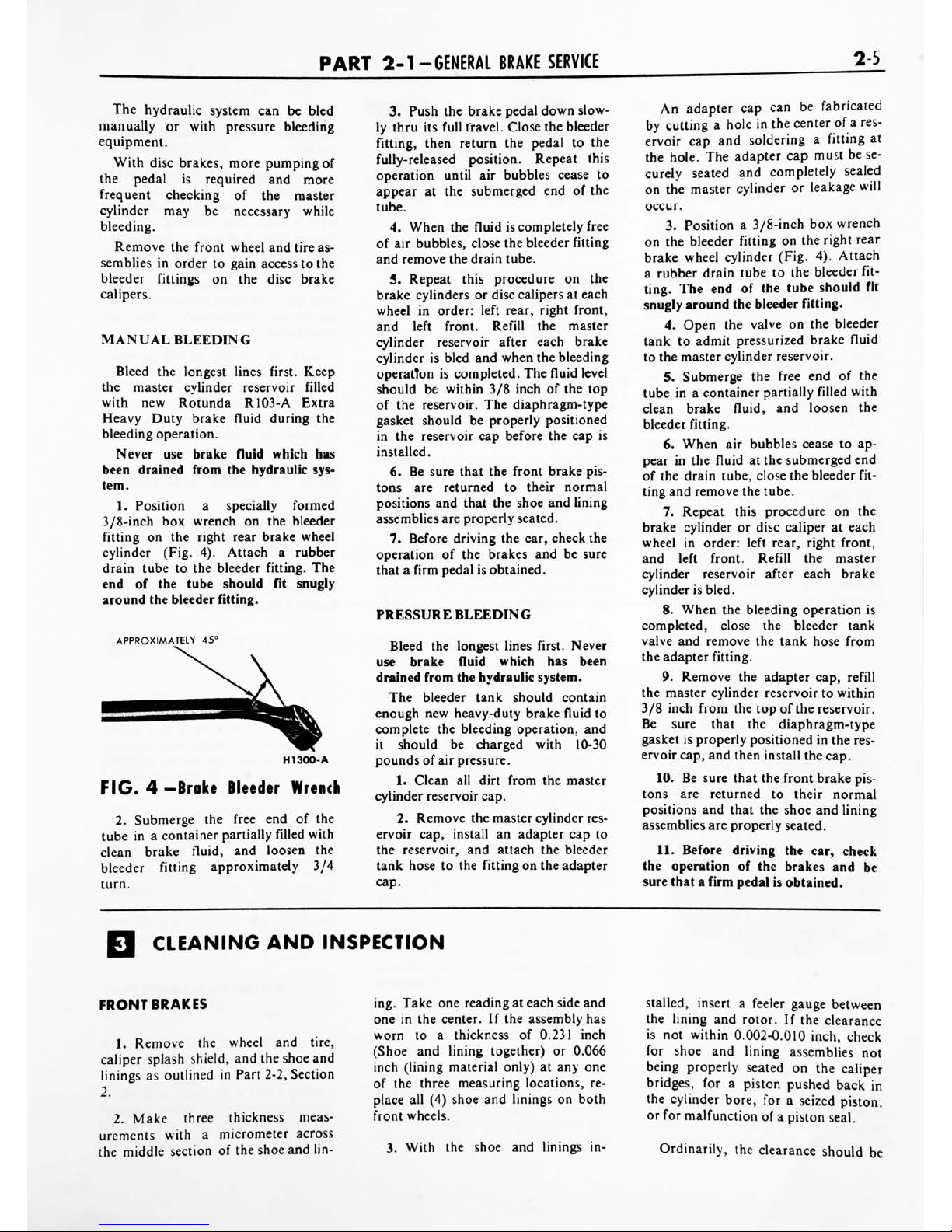
1.
Position
a
specially
formed
3/8-inch
box
wrench
on
the
bleeder
fitting
on
the
right
rear
brake
wheel
cylinder
(Fig.
4).
Attach
a
rubber
drain
tube
to
the
bleeder
fitting.
The
end
of
the
tube
should
fit
snugly
around
the
bleeder
fitting.
APPROXIMATELY
45
HI
300-
A
FIG.
4
-Brake
Bleeder
Wrench
2.
Submerge
the
free
end
of
the
tube
in
a
container
partially
filled
with
clean
brake
fluid,
and
loosen
the
bleeder
fitting
approximately
3/4
turn.
3.
Push
the
brake
pedal
down
slow
ly
thru
its
full
travel.
Close
the
bleeder
fitting,
then
return
the
pedal
to
the
fully-released
position.
Repeat
this
operation
until air
bubbles
cease
to
appear
at
the
submerged
end
of
the
tube.
4.
When
the
fluid
is
completely
free
of
air
bubbles,
close
the
bleeder
fitting
and
remove
the
drain
tube.
5.
Repeat
this
procedure
on
the
brake
cylinders
or
disc
calipers
at
each
wheel
in
order:
left
rear,
right
front,
and
left
front.
Refill
the
master
cylinder
reservoir
after
each
brake
cylinder
is
bled
and
when
the
bleeding
operation
is
completed.
The
fluid
level
should
be
within
3/8
inch
of
the
top
of
the
reservoir.
The
diaphragm-type
gasket
should
be
properly
positioned
in
the
reservoir
cap
before
the
cap
is
installed.
6.
Be
sure
that
the
front
brake
pis
tons
are
returned
to
their
normal
positions
and
that
the
shoe
and
lining
assemblies
are
properly
seated.
7.
Before
driving
the
car,
check
the
operation
of
the
brakes
and
be
sure
that
a
firm
pedal
is
obtained.
PRESSURE
BLEEDING
Bleed
the
longest
lines
first.
Never
use
brake
fluid
which
has
been
drained
from
the
hydraulic
system.
The
bleeder
tank
should
contain
enough
new
heavy-duty
brake
fluid
to
complete
the
bleeding
operation,
and
it
should
be
charged
with
10-30
pounds
of
air
pressure.
1.
Clean
all
dirt
from
the
master
cylinder
reservoir
cap.
2.
Remove
the
master
cylinder
res
ervoir
cap,
install
an
adapter
cap
to
the
reservoir,
and
attach
the
bleeder
tank
hose
to
the
fitting
on
the
adapter
cap.
An
adapter
cap
can
be
fabricated
by
cutting
a
hole
in
the
center
of
a
res
ervoir
cap
and
soldering
a
fitting
at
the
hole.
The
adapter
cap
must
be
se
curely
seated
and
completely
sealed
on
the
master
cylinder
or
leakage
will
occur.
3.
Position
a
3/8-inch
box
wrench
on
the
bleeder
fitting
on
the
right
rear
brake
wheel
cylinder
(Fig.
4).
Attach
a
rubber
drain
tube
to
the
bleeder
fit
ting.
The
end
of
the
tube
should
fit
snugly
around
the
bleeder
fitting.
4.
Open
the
valve
on
the
bleeder
tank
to
admit
pressurized
brake
fluid
to
the
master
cylinder
reservoir.
5.
Submerge
the
free
end
of
the
tube
in
a
container
partially
filled
with
clean
brake
fluid,
and
loosen
the
bleeder
fitting.
6.
When
air
bubbles
cease
to
ap
pear
in
the
fluid
at
the
submerged
end
of
the
drain
tube,
close
the
bleeder
fit
ting
and
remove
the
tube.
7.
Repeat
this
procedure
on
the
brake
cylinder
or
disc
caliper
at
each
wheel
in
order:
left
rear,
right
front,
and
left
front.
Refill
the
master
cylinder
reservoir
after
each
brake
cylinder
is
bled.
8.
When
the
bleeding
operation
is
completed,
close
the
bleeder
tank
valve
and
remove
the
tank
hose
from
the
adapter
fitting.
9.
Remove
the
adapter
cap,
refill
the
master
cylinder
reservoir
to
within
3/8
inch
from
the
top
of
the
reservoir.
Be
sure
that
the
diaphragm-type
gasket
is
properly
positioned
in
the
res
ervoir
cap,
and
then
install
the
cap.
10.
Be
sure
that
the
front
brake
pis
tons
are
returned
to
their
normal
positions
and
that
the
shoe
and
lining
assemblies
are
properly
seated.
11.
Before
driving
the
car,
check
the
operation
of
the
brakes
and
be
sure
that
a
firm
pedal
is
obtained.
CLEANING
AND
INSPECTION
FRONT
BRAKES
1.
Remove
the
wheel
and
tire,
caliper
splash
shield,
and
the
shoe
and
linings
as
outlined
in
Part
2-2,
Section
2.
2.
Make
three
thickness
meas
urements
with
a
micrometer
across
the
middle
section
of
the
shoe
and
lin
ing.
Take
one
reading
at
each
side
and
one
in
the
center.
If
the
assembly
has
worn
to
a
thickness
of
0.231
inch
(Shoe
and
lining
together)
or
0.066
inch
(lining
material
only)
at
any
one
of
the
three
measuring
locations,
re
place
all
(4)
shoe
and
linings
on
both
front
wheels.
3.
With
the
shoe
and
linings
in
stalled,
insert
a
feeler
gauge
between
the
lining
and
rotor.
If
the
clearance
is
not
within
0.002-0.010
inch,
check
for
shoe
and
lining
assemblies
not
being
properly
seated
on
the
caliper
bridges,
for
a
piston
pushed
back
in
the
cylinder
bore,
for
a
seized
piston,
or
for
malfunction
of
a
piston
seal.
Ordinarily,
the
clearance
should
be
2-6
GROUP
2
-BRAKES
0.002-0.010
inch.
However,
if
the
car
was
stopped
by
a
brake
application
just
prior
to
checking
the
clearance,
the
brakes
may
drag
slightly.
4.
To
check
rotor
runout,
first
eliminate
the
wheel
bearing
end
play
by
tightening
the
adjusting
nut.
After
tightening
the
nut
check
to
see
that
the
rotor
can
still
be
rotated.
5.
Clamp
a
dial
indicator
to
the
caliper
housing
so
that
the
stylus
con
tacts
the
rotor
at
a
point
approximate
ly
1
inch
from
the
outer
edge.
Rotate
the
rotor
and
take
an
indicator
read
ing.
If
the
reading
exceeds
0.002
inch
total
indicator
runout,
replace
the
rotor.
Do
not
attempt
to
refinish
a
rotor
that
indicates
runout
in
excess
of
specification.
When
the
runout
check
is
finished
be
sure
to
adjust
the
bearings
as
outlined
in
Group
3,
in
order
to
prevent
bearing
failure.
6.
Check
the
rotor
for
scoring.
Minor
scores
can
be
removed
with
a
fine
emery
cloth.
If
the
rotor
is
exces
sively
scored
replace
it.
7.
Visually
check
the
caliper.
Ifitis
cracked
or
if
excess
leakage
is
evident,
it
should
be
replaced.
Slight
leakage
or
seized
pistons
indicate
removal
and
disassembly.
8.
If
upon
disassembly
the
caliper
is
found
to
be
distorted
or
damaged,
or
if
the
cylinder
bores
are
scored
or
excessively
worn,
replace
the
as
sembly.
The
two
halves
of
the
caliper
as
sembly
should
never
be
separated.
Damage
or
failure
of
one
requires
re
placement
of
both
as
a
unit.
REAR
BRAKES
1.
Remove
the
wheel
from
the
drum,
and
remove
the
drum
as
out
lined
in
Part
2-2,
Section
2.
Wash
all
the
parts
except
the
brake
shoes
in
a
cleaning
fluid
and
dry
with
com
pressed
air.
2.
Brush
all
dust
from
the
carrier
plate
and
interior
of
the
brake
drum.
3.
Inspect
the
brake
shoes
for
ex
cessive
lining
wear
or
shoe
damage.
If
the
lining
is
worn
to
within
1/32
inch
of
the
rivet
heads
or
if
the
shoes
are
damaged,
they
must
be
replaced.
Rep
lace
any
lining
that
has
been
oil
satu
rated.
Replace
the
lining
in
axle
sets.
Prior
to
replacement
of
the
lining,
the
drum
diameter
should
be
checked
to
determine
if
oversize
linings
must
be
installed.
4. Check
the
condition
of
the
brake
shoes,
retracting
springs,
and
drum
for
signs
of
overheating.
If
the
shoes
have
a
slight
blue
coloring,
or
if
the
springs
show
a
change
in
free
length,
indicating
overheating,
replacement
of
the
retracting
and
hold
down
springs
is
necessary.
Overheated
springs
lose
their
pull and
could
cause
the
new
lin
ing
to
wear
prematurely
if
they
are
not
replaced.
5.
If
the
car
has
30,000
or
more
miles
of
operation
on
the
brake
lin
ings,
or
signs
of
overheating
are
pres
ent
when
relining
brakes,
the
wheel
cylinders
should
be
disassembled
and
inspected
for
wear
and
dirt
in
the
cylinder.
The
cylinder
cups
and
other
parts
contained
in
the
overhaul
kit
should
be
replaced,
thus
avoiding
future
problems.
6.
Inspect
all
other
brake
parts
and
replace
any
that
are
worn
or
da
maged.
7.
Inspect
the
brake
drums
and,
if
necessary,
refinish.
Refer
to
Part
2-2,
Section
4
for
refinishing.
2-7
PART
2-2
BRAKE
SYSTEM
Section
Page
Section
Page
Description
and
Operation
2-7
Disc
Brake
Assemblies
2-7
Hydraulic
Self-
Adjusting
Brake
System
2-8
Booster
System
2-9
Parking
Brake
2-9
In-Car
Adjustments
and
Repairs
2-10
Disc
Brake
Caliper
Assembly
2-11
Front
Wheel
Hub
and
Rotor
Assembly
-
Disc Brakes
2-11
Disc
Brake
Rotor
Splash
Shield
2-12
Proportioning
Valve
2-12
Brake
Shoe
Adjustments
2-12
Rear
Brake
Drum
2-13
Brake
Shoes
and
Adjusting
Screw
2-13
Disc
Brake
Shoe
and
Lining
Replacement
2-13
Wheel Cylinder
Repair
2-14
Wheel
Cylinder
Replacement
2-15
Brake
Carrier
Plate
Replacement
2-15
Hydraulic
Lines
2-15
Brake
Tube
Replacement
2-15
Brake
Hose
Replacement
2-15
Removal
and
Installation
2-16
Master
Cylinder
-
Power
Brakes
2-16
Booster
Unit
2-17
Brake
Pedal
-
Automatic
Transmission
2-17
Parking
Brake
Control
Assembly
2-18
Parking
Brake
Vacuum
Power
Unit
2-19
Parking
Brake
Equalizer
to
Control
Cable
2-19
Parking
Brake
Equalizer
to
Rear
Wheel
Cable
2-19
Major
Repair
Operations
2-20
Brake
Drum
Refinishing
2-20
Brake
Shoe
Relining
2-20
Master
Cylinder
2-20
DESCRIPTION
AND
OPERATION
The
1966
Thunderbird
brake
system
employs
disc
brakes
on
the
front
wheels
and
single
anchor,
internal
ex
panding
and
self-adjusting
brake
as
semblies
on
the
rear
wheels.
The
sys
tem
is
powered
by
a
vacuum
booster
as
standard
equipment.
The
master
cylinder
converts
physi
cal
force
from
the
brake
pedal
and
booster
into
hydraulic
pressure
against
the
pistons
in
the
calipers
(front
wheels)
or
in
the
wheel
cylinders
(rear
wheels).
The
pistons
in
turn
convert
hydraulic
pressure
back
into
physical
force
at
the
discs
and
brake
shoes.
DISC
BRAKE
ASSEMBLIES
-FRONT
WHEELS
RELATION
AND
FUNCTION
OF
COMPONENT
PARTS
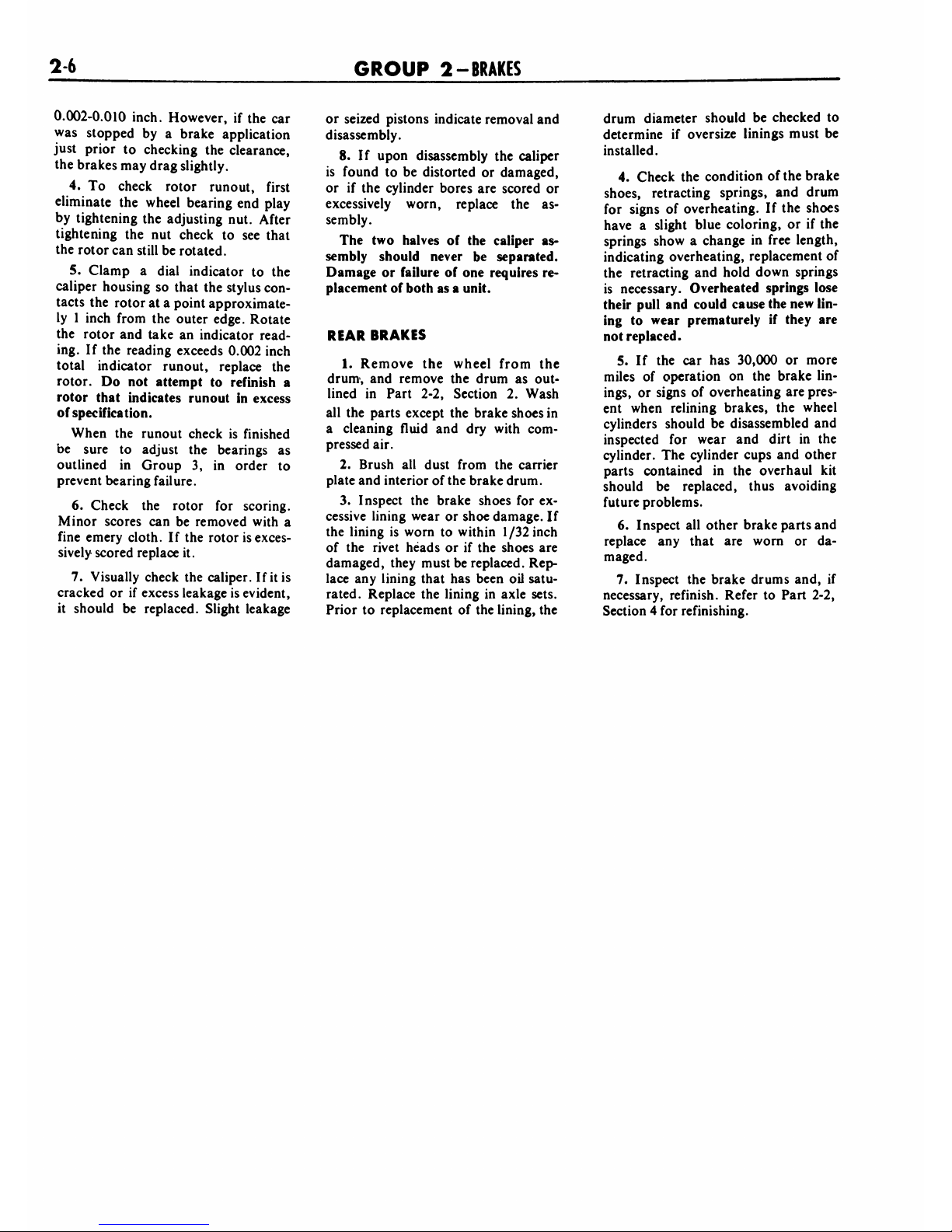
The
disc
brake
is
a
fixed
caliper,
opposed
piston,
non-energized,
ven
tilated
disc
type,
actuated
by
a
hy
draulic
system
(Fig.
1).
There
is
no
lateral
movement
of
either
the
disc
(rotor)
or
the
caliper.
The
caliper
as
sembly
consists
of
two
caliper
housings
bolted
together
with
each
half
containing
two
cylinder
bores
of
1
15/16
inch
diameter.
Each
cylinder
bore
contains
a
piston
with
an
at
tached
molded
rubber
dust
boot
to
seal
the
cylinder
bore
from
con
tamination*
(Fig.
2).
Square-section
rubber
piston
seals
are
positioned
in
grooves
in
the
cylinder
bores.
The
piston
seals
perform
three
im
portant
tasks:
1.
They
provide
hydraulic
sealing
between
the
cylinders
and
pistons.
2.
They
return
the
pistons
to
released
position,
when
hydraulic
pressure
is
released.
3.
They
maintain
the
shoes
in
cor
rect
adjustment
at
all
times
(compar
able
to
the
automatic
adjusters
in
drum-type
brakes.
The
cylinders
are
connected
hy-
draulically
by
means
of
internal
pas
sages
in
the
caliper
housings
and
an
external
transfer
tube
between
the
two
halves
of
the
caliper
assembly.
One
CALIPER
SPLASH
SHIELD
EXTERNAL
TRANSFER
HUB
AND
ROTOR
ASSEMBLY
DER
SCREW
H1368-B
FIG.
1
Disc
Brake
Assembly
bleeder
screw
and
fluid
inlet
fitting
is
provided
on
each
caliper
assembly.
The
shoe
and
lining
assemblies
are
located
in
between
parallel
machined
abutments
within
the
caliper,
and
are
supported
radially
by
tabs
on
the
2-8
GROUP
2
-BRAKES
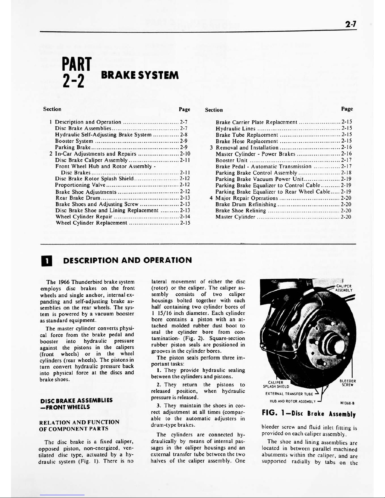
CALIPER
HOUSING
CALIPER
TO
ROTOR
CLEARANCE
TRANSFER
TUBE
-ROTOR
PISTON
OUST
BOOT
RETAINING
GROVE
PISTON
SEAL
FIG.
2
Caliper
Assembly
Sectional
View
outer
ends
of
the
shoe
assemblies
(Fig.
21).
The
shoes
slide
axially
in
the
caliper
abutments
by
means
of
the
tabs
which
ride
on
machined
ledges
(bridges)
when
hydraulic
pressure
is
applied
to
the
piston
(Fig.
7).
A
shoe
and
lining
assembly
consists
of
fric
tion
material
bonded
to
a
metal
plate
called
the
shoe.
It
is
replaced
as
a
unit.
Brake
torque
is
absorbed
by
the
mating
of
the
shoe
end
against
the
caliper
abutments
(Fig.
21).
A
splash
shield
is
attached
to
the
top
of
the
caliper
to
retain
the
shoe
and
lining
assemblies
and
reduce
contamination.
The
caliper
assembly
is
mounted
on
the
front
wheel
spindle
to
the
rear
of
the
wheel
vertical
centerline.
The
cast
iron
disc
is
of
the
ventilat
ed
rotor
type
incorporating
forty
fins
and
is
staked
to,
and
rotates
with,
the
wheel
hub.
The
outside
diameter
of
the
rotor
is
1
1
.87
inches
and
the
inside
diameter
is
7.875
inches.
This
type
of
design
increases
cooling
area
and
per
mits
circulation
of
air
through
the
rotor
resulting
in
more rapid
cooling
of
the
brake.
A
splash
shield
bolted
to
the
spindle
is
used
primarily
to
prevent
road
contaminants
from
con
tacting
the
inboard
rotor
and
lining
surfaces
(Fig.
8).
The
wheel
provides
protection
for
the
outboard
surface
of
the
rotor.
OPERATION
As
the
brake
pedal
is
depressed,
hydraulic
pressure
from
the
master
cylinder
forces
the
pistons
out
of
the
caliper
bores
against
their
respective
shoe
and
lining
assemblies.
The
force
of
the
pistons
against
the
shoes
moves
the
linings
against
both
sides
of
the
re
volving
rotor
to
effect
braking
action.
During
brake
application,
the
rub
ber
seal
in
each
piston
stretches
as
the
piston
moves
against
the
shoe
(Fig.
3).
When
the
hydraulic
pressure
against
the
piston
is
released,
the
seal
relaxes
or
rolls
back.
This
roll-back
action
pulls
the
piston
away
from
the
shoe
approximately
0.005
inch
to
relieve
the
force
of
the
lining
against
the
rotor
and,
thereby,
provide
the
required
running
clearance.
Also,
in
herent
rotor
runout
contributes
to
the
maintenance
of
running
clearance.
Automatic
adjustment
is
achieved
by
the
pistons
sliding
in
the
seals
out
ward
from
the
cylinder
bores.
The
pis
ton
gradually
changes
its
position
rel
ative
to
the
seal
as
the
lining
wears
and,
thus,
maintains
the
correct
ad
justment
location
at
all
times.
PISTON
t
When
the
brakes
are
in
the
unap
plied
position,
there
is
no
hydraulic
pressure
to
the
calipers
because
the
fluid
source
at
the
master
cylinder
by
passes
the
residual
check
valve.
A
proportioning
valve
located
between
the
master
cylinder
and
the
rear
brake
wheel
cylinder
provides
bal
anced
braking
action
between
the
front
and
the
rear
brakes
under
a
wide
range
of
braking
conditions
(Fig.
16).
By
regulating
the
hydraulic
pressure
applied
to
the
rear
wheel
cylinders,
the
valve
limits
rear
braking
action
when
high
pressures
are
required
at
the
front
brakes.
In
this
manner,
pre
mature
rear
wheel
skid
is
prevented.
The
proportioning
valve
is
serviced
as
an
assembly
and
is
never
adjusted
or
overhauled.
SELF-ADJUSTING
BRAKE
ASSEMBLIES-REAR
WHEELS
The
self-adjusting
brake
mechanism
consists
of
a
cable,
cable
guide,
adjust
ing
lever,
adjusting
screw
assembly,
and
adjuster
spring
(Fig.
4).
The
cable
is
hooked
over
the
anchor
pin
at
the
top
and
is
connected
to
the
lever
at
the
bottom.
The
cable
is
connected
to
the
secondary
brake
shoe
by
means
of
the
cable
guide.
The
adjuster
spring
is
hooked
to
the
primary
brake
shoe
and
to
the
lever.
The
automatic
ad
juster
operates
only
when
the
brakes
are
applied
while
the
car
is
moving
rearward
and
only
when
the
secon
dary
shoe
is
free
to
move
toward
the
drum
beyond
a
predetermined
point.
With
the
car
moving
rearward
and
the
brakes
applied,
the
wrap-around
action
of
the
shoes
following
the
drum
forces
the
upper
end
of
the
primary
shoe
against
the
anchor
pin.
The
ac
tion
of
the
wheel
cylinder
moves
the
upper
end
of
the
secondary
shoe
away
CALIPER
HOUSING
BRAKES
APPLIED
BRAKES
RELEASED
HI
370-
A
FIG.
3
-Function
of
Piston
Seal
 Loading...