

Ford Thundenbind 1961, 1961 Thunderbind Shop Manual
Copyright © 2009, Forel Publishing Company, LLC, Woodbridge, Virginia
All Rights Reserved. No part of this book may be used or reproduced in any manner whatsoever
without written permission of Forel Publishing Company, LLC. For information write to Forel
Publishing Company, LLC, 3999 Peregrine Ridge Ct., Woodbridge, VA 22192
1961 Ford Thunderbird Shop Manual
EAN: 978-1-60371-011-4
ISBN: 1-60371-011-6
Forel Publishing Company, LLC
3999 Peregrine Ridge Ct.
Woodbridge, VA 22192
Email address: webmaster@ForelPublishing.com
Website: http://www.ForelPublishing.com
This publication contains material that is reproduced and distributed under a license from Ford
Motor Company. No further reproduction or distribution of the Ford Motor Company material is
allowed without the express written permission of Ford Motor Company.
NNoottee ffrroomm tthhee EEddiittoorr
This product was created from the original Ford Motor Company’s publication. Every effort has
been made to use the original scanned images, however, due to the condition of the material;
some pages have been modified to remove imperfections.
Although every effort was made to ensure the accuracy of this book, no representations or
warranties of any kind are made concerning the accuracy, completeness or suitability of the
information, either expressed or implied. As a result, the information contained within this book
should be used as general information only. The author and Forel Publishing Company, LLC
shall have neither liability nor responsibility to any person or entity with respect to any loss or
damage caused, or alleged to be caused, directly or indirectly by the information contained in
this book. Further, the publisher and author are not engaged in rendering legal or other
professional services. If legal, mechanical, electrical, or other expert assistance is required, the
services of a competent professional should be sought.
Disclaimer
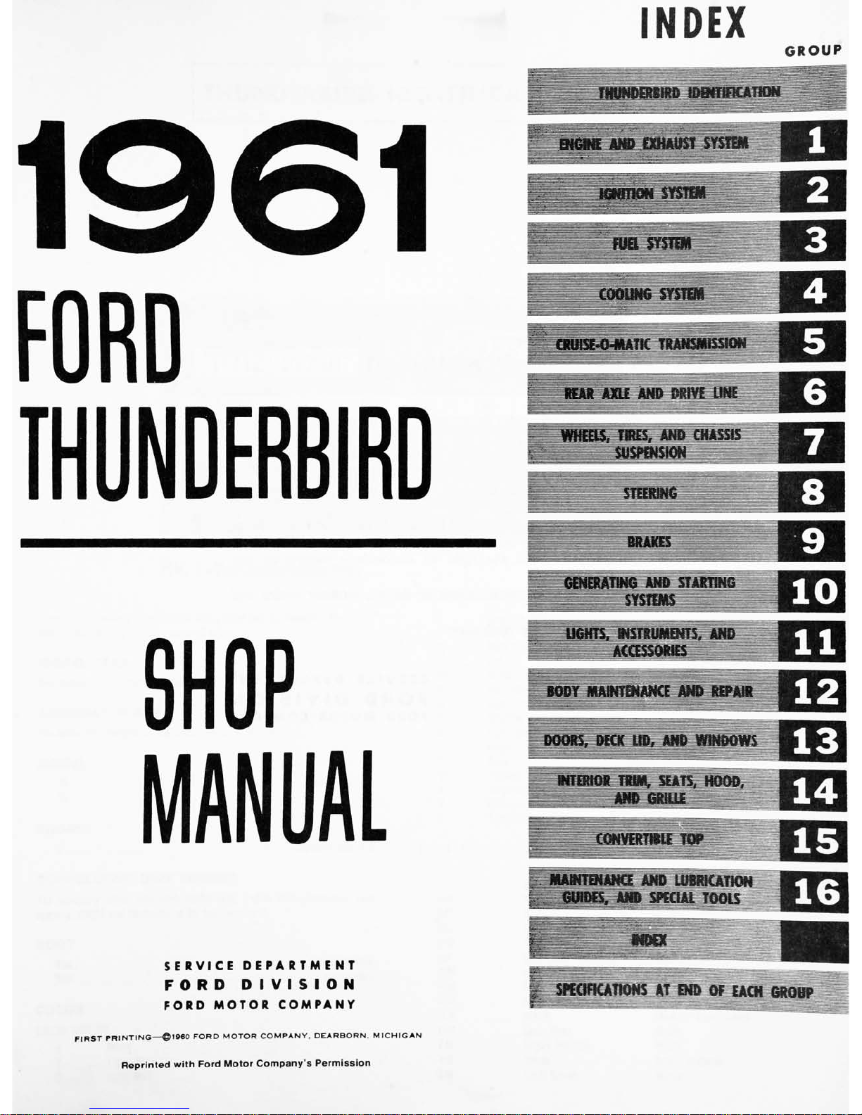
INDEX
GROUP
SERVICE
DEPARTMENT
FORD
DIVISION
FORD
MOTOR
COMPANY
FIRST
PRINTING
1900
FORD
MOTOR
COMPANY,
DEARBORN.
MICHIGAN
Reprinted
with
Ford
Motor Company's
Permission
FOREWORD
This
manual
provides
information
for
the
proper
servicing
of
the
1961
Thunderbird.
The
descriptions
and
specifications
contained
in
this
manual
were
in
effect
at
the
time
the
manual
was
approved
for
printing.
The
Ford
Division
of
Ford
Motor
Company
reserves
the
right
to
discontinue
models
at
any
time,
or
change
specifications
or
design,
without notice
and
without
incurring
obligation.
SERVICE
DEPARTMENT
FORD
DIVISION
FORD
MOTOR
COMPANY
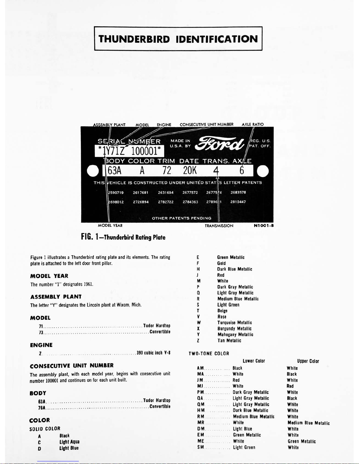
THUNDERBIRD
IDENTIFICATION
>EMBLY
PLANT
MODEL
ENGINE
CONSECUTIVE
UNIT
NUMBER
AXLE
RATIO
1Y71Z
100001
TP
MADE
IN
U.S.A.
BY
&&F<1'
*EG.
U.S.
'AT.
OFF.
BODY
COLOR
TRIM
DATE
TRANS.
A.
THIS
U/EHICLE
IS
CONSTRUCTED
UNDER
UNITED
STAT
CS
LETTER
PATENTS
2590719
2617681
2631694
2677572
26775ir4
2683578
'.698012
2726894
2782722
2784363
27896
1
2810447
OTHER
PATENTS
PENDING
MODEL
YEAR
FIG.
1
Thunderbird
Rating
Plate
TRANSMISSION
NIOOl-B
Figure
1
illustrates
a
Thunderbird
rating
plate
and
its
elements.
The
rating
plate
is
attached
to
the
left
door
front
pillar.
MODEL
YEAR
The
number
"1"
designates
1961.
ASSEMBLY
PLANT
The
letter
"Y"
designates
the
Lincoln
plant
at
Wixom,
Mich.
MODEL
71
Tudor
Hardtop
73
Convertible
ENGINE
1
390
cubic
inch
V-8
CONSECUTIVE
UNIT
NUMBER
The
assembly
plant,
with
each
model
year,
begins
with
consecutive
unit
number
100001
and
continues
on
for
each
unit
built.
BODY
53A
Tudor
Hardtop
70A
Convertible
COLOR
SOLID
COLOR
A
Black
C
Light
Aqua
D
Light
Blue
E
Green
Metallic
F
Gold
H
Dark
Blue
Metallic
J
Red
M
White
P
Q
R
Dark
Gray
Metallic
Light
Gray
Metallic
Medium
Blue
Metallic
S
T
V
Light
Green
Beige
Rose
W
Turquoise
Metallic
X
Y
z
Burgundy
Metallic
Mahogany
Metallic
Tan
Metallic
TWO-TONE
COLOR
Lower
Color
AM
Black
MA
White
JM
Red
MJ
White
PM
Dark
Gray
Metallic
QA
Light
Gray
Metallic
QM
Light
Gray
Metallic
HM
Dark
Blue
Metallic
RM
Medium
Blue
Metallic
MR
White
DM
Light
Blue
EM
Green
Metallic
ME
White
SM
Light
Green
Upper
Color
White
Black
White
Red
White
Black
White
White
White
Medium
Blue
Metallic
White
White
Green
Metallic
White
TWO-TONE
COLOR-Continued
Lower
Color
Upper
Color
WM
Turquoise
Metallic
White
MW
White
Turquoise
Metallic
CM
Light
Aqua
White
TZ
Beige
Tan
ZM
Tan
White
MZ
White
Tan
YM
Mahogany
Metallic
White
FM
Gold
White
VA
Rose
Black
VM
Rose
White
XM
Burgundy
Metallic
White
DATE
The
date
code
shows
the
day
and
month
when
the
Thunderbird
was
com
pleted.
The
months
are
designated
as
follows:
A
January
G
July
B
February
H
August
C
March
J
September
D
April
K
October
E
May
L
November
F
June
M
December
TRANSMISSION
4
AXLE
6
3..
H.
Cruise-O-Matic
3.00
to
1
3.10
to
1
2.91
to
1
GROUP
I
ENGINE
AND
EXHAUST
SYSTEM
PAGE
PART
1-1
ENGINE
1.
P
A
RT
1-2
EXHAUST
SYSTEM
1-45
PART
1-3
SPECIFICATIONS
1-47
12
Section
Page
1
Description
1-2
2
Engine
Trouble
Diagnosis.
.
1-6
3
Tune-Up
1-12
Engine
Compression
Test
.
1-13
Camshaft
Lobe
Lift
1-16
Valve
Clearance
1-16
Manifold
Vacuum
Test.
.
1-17
4
Engine
Removal
and
Installation
1-17
5
In-Chassis
Repair
Operations
1-19
Engine
Supports
1-19
Section
Page
Valve
Rocker
Aim
Shaft
Assembly
1-19
Intake
Manifold
1-21
Exhaust
Manifold
1-22
Regulator
Valve
Positive
Crankcase
Ventilation
System
1-23
Cylinder
Heads
and
Valves
1-23
Valve
Stem
Seal
Replacement
1-26
Cylinder
Front
Cover
and
Timing
Chain
1-27
Section
Page
Camshaft
1-29
Camshaft
Rear
Bearing
Bore
Plug
Replacement.
.
1-30
Hydraulic
Valve
Lifter
Replacement
1-30
Crankshaft
Lower
Rear
Oil
Seal
Replacement
1-31
Main
and
Connecting
Rod
Bearing
Replacement
1-32
Piston
and
Connecting
Rod
Assembly
1-32
Flywheel
1-36
Oil
Pan
and
Oil
Pump
..
.
1-36
Oil
Filter
Replacement.
.
.
1-36
6
Work
Stand
Repair
Operations
1-38
Crankshaft
1-38
Camshaft
Bearing
Replacement
1-40
Engine
Disassembly
1-40
Cylinder
Block
Cleaning
and
Inspection
1-42
Engine
Assembly
1-42
7
Crankcase
Ventilation
System
Maintenance
1-44
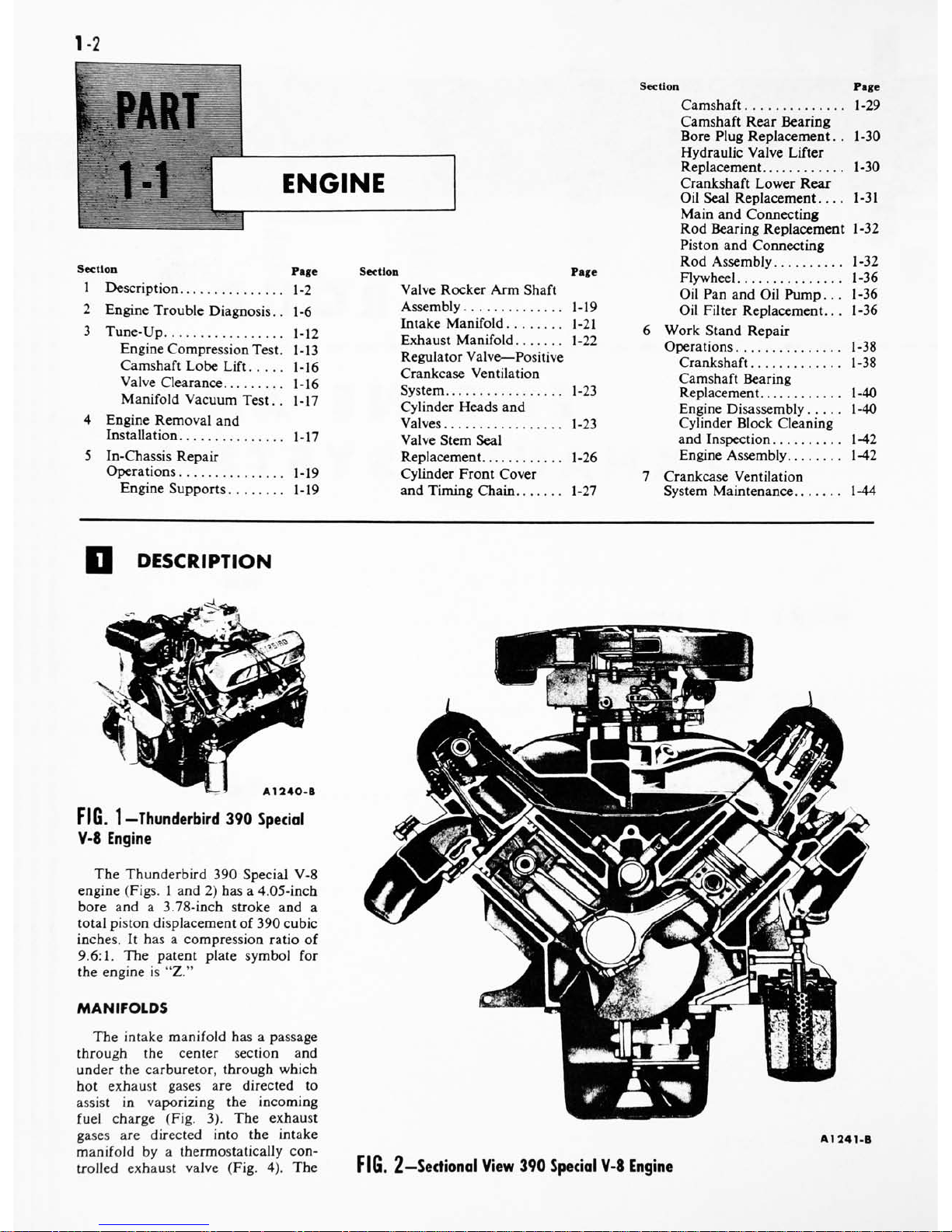
DESCRIPTION
A1240-B
FIG.
1
Thunderbird
390
Special
V-8
Engine
The
Thunderbird
390
Special
V-8
engine
(Figs.
1
and
2)
has
a
4.05-inch
bore
and
a
3.78-inch
stroke
and
a
total
piston
displacement
of
390
cubic
inches.
It
has
a
compression
ratio
of
9.6:1.
The
patent
plate
symbol
for
the
engine
is
"Z."
MANIFOLDS
The
intake
manifold
has
a
passage
through
the
center
section
and
under
the
carburetor,
through
which
hot
exhaust
gases
are
directed
to
assist
in
vaporizing
the
incoming
fuel
charge
(Fig.
3).
The
exhaust
gases
are
directed
into
the
intake
manifold
by
a
thermostatically
con
trolled
exhaust
valve
(Fig.
4).
The
A1241-B
FIG.
2
-Sectional
View
390
Special
V-8
Engine

PART
1-1
-ENGINE
1-3
AIR
INLET
A1242-A
FIG.
3
Intake
Manifold
Exhaust
Gas
Passages
valve
is
located
at
the
outlet
of
the
right
exhaust
manifold.
When
the
valve
is
in
the
closed
or
heat
on
posi
tion,
part
of
the
exhaust
gases
are
di
rected
from
the
right
exhaust
mani
fold,
through
the
heat
riser
passage,
to
the
left
exhaust
manifold.
When
the
valve
is
open
or
in
the
heat
off
position,
more
of
the
exhaust
gases
from
the
right
manifold
are
permitted
OPEN
(HEAT
OFF)
CLOSED
(HEAT
ON)
A1073-A
FIG.
4
Exhaust
Gas
Control
Valve
4
1243-A
FIG.
5-lntake
Manifold
Fuel
Passages
AIR HEAT
CHAMBER
A
1206-
A
FIG.
6
Automatic
Choke
Heat
Chamber
to
flow
directly
out
of
the
exhaust
system
in
the
normal
manner.
The
intake
manifold
has
two
sets
of
fuel
passages,
each
with
its
own
separate
inlet
connection
to
the
car
buretor
(Fig.
5).
The
right
barrels
of
the
carburetor
feed Nos.
1,
4,
6,
and
7
cylinders
and
the
left
barrels
feed
Nos.
2,
3,
5,
and
8
cylinders.
The
distributor
is
mounted
at
the
left front
of
the
intake
manifold.
Warm
air
for
the
automatic
choke
is
drawn
from
the
heat
chamber
of
the
right
exhaust
manifold
(Fig.
6).
CYLINDER
HEADS
The
cylinder
head
assemblies
con
tain
the
valves
and
the
valve
rocker
arm
shaft
assembly.
The
combus
tion
chambers are
machined
in
the
head.
Valve
guides
are
an
integral
VALVE
OPEN
LIFTER
BODY
A1244-A
FIG.
7
-Valve
Port
Arrangement
part
of
the
head.
The
valves
are
ar
ranged
from
front
to
rear
on
both
banks
E-I-E-I-I-E-I-E
(Fig.
7).
CYLINDER
BLOCK
The
cylinders
are
numbered
from
front
to
rear,
on
the
right
bank
1,
2,
3
and
4
and
on
the
left
bank
5,
6,
7
and
8.
The
firing
order
is
1-5-4-2-6-3-
7-8.
The
oil
pump,
mounted
inside
the
oil
pan
at
the
front,
is
driven
by
the
distributor
through
an
intermediate
drive
shaft.
The
crankshaft
is
supported
by
five
main
bearings.
Crankshaft
end
thrust
is
controlled
by
the
flanges
of
the
No.
3
main
bearing.
The
pistons
have
two
compression
rings
and
one
oil
control
ring.
The
top
compression
ring
is
chrome-
plated
and
the
lower
compression
ring
is
phosphate-coated.
The
oil
con
trol
ring
assembly
consists
of
a
ser
rated
spring
and
two
chrome-plated
steel
rails.
VALVE
TRAIN
The
intake
and
exhaust
valve
as
semblies
are
the
rotating-type
which
VALVE
CLOSED
DISC
VALVE
BASE
CIRCLE
A1245-A
FIG.
8
Typical
Hydraulic
Valve
Lifter
Operation
14
GROUP
1-
ENGINE
AND
EXHAUST
SYSTEM
rotate
each
time
the
valve
opens
and
closes.
The
push
rods
are
solid
steel
with
oil
cushioned
sockets.
The
camshaft
is
supported
by
five
bearings
pressed
into
the
block.
It
is
driven
by
a
sprocket
and
timing
chain
in
mesh
with
a
sprocket
on
the
crank
shaft.
Camshaft
end
play
is
controlled
by
a
thrust
button
and
spring
located
between
the
camshaft
sprocket
bolt
and
the
cylinder
front
cover.
An
ec
centric,
bolted
to
the
front
end
of
the
camshaft,
operates
the
fuel
pump.
Hydraulic
valve
lifters
are
used
which
provide
zero
valve
lash.
The
operation
and
parts
identification
of
the
hydraulic
valve
lifters
are
shown
in
Fig.
8.
When
the
valve
is
closed,
the
lifter
assembly
is
on
the
base
circle
of
the
camshaft
lobe
and
the
valve
push
rod
is
in
its
lowest
position.
With
the
lifter
assembly
in
this
position,
the
plunger
spring
expands
forcing
the
plunger
upward.
This
action
is
trans
mitted
to
the
valve
rocker
arm
via
the
valve
push
rod
until
there
is
solid
contact
between
the
valve
and
the
valve
end
of
the
valve
rocker
arm
(zero
valve
lash).
In
this
position,
the
oil
hole
in
the
lifter
and
plunger
is
indexed
with
the
lifter
oil
gallery
and
oil
is
forced
under
pressure
into
the
plunger.
This
creates
a
pressure
dif
ferential
above
and
below
the
valve
disc.
The
high
pressure
above
the
valve
disc
forces
the
valve
disc
open
and
the
oil
fills
the
area
below
the
plunger,
equalizing
the
pressure
on
each
side
of
the
valve
disc.
Whenever
clearance
between
the
valve
and
the
valve
rocker
arm
tends
to
be
present,
the
plunger
spring
expands
pushing
the
plunger
until
there
is
solid
contact
between
all
parts
of
the
valve
train
mech
anism.
As
the
camshaft
rotates
(valve
opening),
the
valve
lifter
is
raised
and
the
sudden
increase
in
oil
pres
sure
below
the
plunger
forces
the
valve
disc
closed
and
the
lifter
be
comes
a
hydraulic
ram.
During
this
period,
a
slight
leakage
of
oil
from
below
the
plunger
occurs.
As
the
high
point
on
the
camshaft
lobe
ro
tates
past
the
lifter,
the
push
rod
forces
the
valve
lifter
down
and
re
seats
the
valve.
The
pressure
on
the
oil
below
the
plunger
is
relieved
and
the
valve
disc
opens
so
that
the
chamber
can
again
be
filled.
This
cycle
is
repeated
for
each
revolution
of
the
camshaft.
Kd
if
-L
If
FIG.
9
Lubrication
System
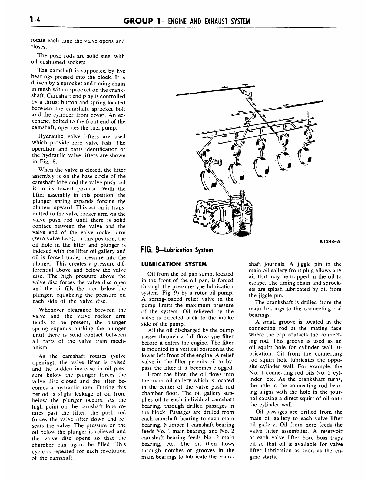
LUBRICATION
SYSTEM
Oil
from
the
oil
pan
sump,
located
in
the
front
of
the
oil
pan,
is
forced
through
the
pressure-type
lubrication
system
(Fig.
9)
by
a rotor
oil
pump.
A
spring-loaded
relief
valve
in
the
pump
limits
the
maximum
pressure
of
the
system.
Oil
relieved
by
the
valve
is
directed
back
to
the
intake
side
of
the
pump.
All
the
oil
discharged
by
the
pump
passes
through
a
full
flow-type
filter
before
it
enters
the
engine.
The
filter
is
mounted
in
a
vertical position
at
the
lower
left
front
of
the
engine.
A
relief
valve
in
the
filter
permits
oil
to
by
pass
the
filter
if
it
becomes
clogged.
From
the
filter,
the
oil
flows
into
the
main
oil
gallery
which
is
located
in
the
center
of
the
valve
push
rod
chamber
floor.
The
oil
gallery
sup
plies
oil
to
each
individual
camshaft
bearing,
through
drilled
passages
in
the
block.
Passages
are
drilled
from
each
camshaft
bearing
to
each
main
bearing.
Number
1
camshaft
bearing
feeds
No.
1
main
bearing,
and
No.
2
camshaft
bearing
feeds
No.
2
main
bearing,
etc.
The
oil
then
flows
through
notches
or
grooves
in
the
main
bearings
to
lubricate
the
crank-
A1246-A
shaft
journals.
A
jiggle
pin
in
the
main
oil
gallery
front
plug
allows
any
air
that
may
be
trapped
in
the
oil
to
escape.
The
timing
chain
and sprock
ets
are
splash
lubricated
by
oil
from
the
jiggle
pin.
The
crankshaft
is
drilled from
the
main
bearings
to
the
connecting
rod
bearings.
A
small groove
is
located
in
the
connecting
rod
at
the
mating
face
where
the
cap
contacts
the
connect
ing
rod.
This
groove
is
used
as
an
oil
squirt
hole
for
cylinder
wall
lu
brication.
Oil
from
the
connecting
rod
squirt
hole
lubricates
the
oppo
site
cylinder
wall.
For
example,
the
No.
1
connecting
rod
oils
No.
5
cyl
inder,
etc.
As
the
crankshaft
turns,
the
hole
in
the
connecting
rod
bear
ing
aligns
with
the
hole
in
the
jour
nal
causing
a
direct
squirt
of
oil
onto
the
cylinder
wall.
Oil
passages
are
drilled
from
the
main
oil
gallery
to
each
valve
lifter
oil
gallery.
Oil
from
here
feeds
the
valve
lifter
assemblies.
A
reservoir
at
each
valve
lifter
bore
boss
traps
oil
so
that
oil
is
available
for
valve
lifter
lubrication
as
soon
as
the
en
gine
starts.
PART
1-1
-ENGINE
1-5
NO.
2
SUPPORT,
LEFT
HEAD
NO.
4
SUPPORT,
RIGHT
HEAD
FROM
NO.
2
CAMSHAFT
BEARING
TO
LEFT
CYLINDER
HEAD,
AND
FROM
NO.
4
CAMSHAFT
BEARING
TO
RIGHT
CYLINDER
HEAD,
A
1247-A
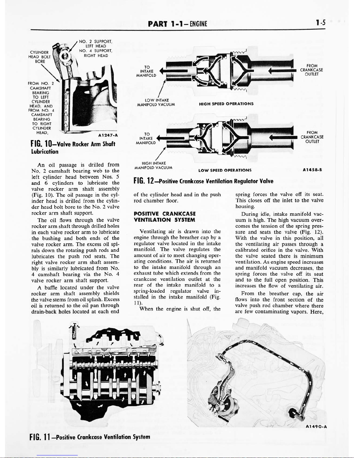
FIG.
10-Valve
Rocker
Arm
Shaft
Lubrication
An
oil
passage
is
drilled
from
No.
2
camshaft
bearing
web
to
the
left
cylinder
head
between
Nos.
5
and
6
cylinders
to
lubricate
the
valve
rocker
arm
shaft
assembly
(Fig.
10).
The
oil
passage
in
the
cyl
inder
head
is
drilled
from
the
cylin
der
head
bolt
bore
to
the
No.
2
valve
rocker
arm
shaft
support.
The
oil
flows
through
the
valve
rocker
arm
shaft
through
drilled
holes
in
each
valve
rocker
arm
to
lubricate
the
bushing
and
both
ends
of
the
valve
rocker
arm.
The
excess
oil
spi
rals
down
the
rotating
push
rods
and
lubricates
the
push
rod
seats.
The
right
valve
rocker
arm
shaft
assem
bly
is
similarly
lubricated
from
No.
4
camshaft
bearing
via
the
No.
4
valve
rocker
arm
shaft
support.
A
baffle
located
under
the
valve
rocker
arm
shaft
assembly
shields
the
valve
stems
from
oil
splash.
Excess
oil
is
returned
to
the
oil
pan
through
drain-back
holes
located
at
each
end
LOW
INTAKE
MANIFOLD
VACUUM
HIGH
SPEED
OPERATIONS
HIGH
INTAKE
MANIFOLD
VACUUM
LOW
SPEED
OPERATIONS
A1458-B
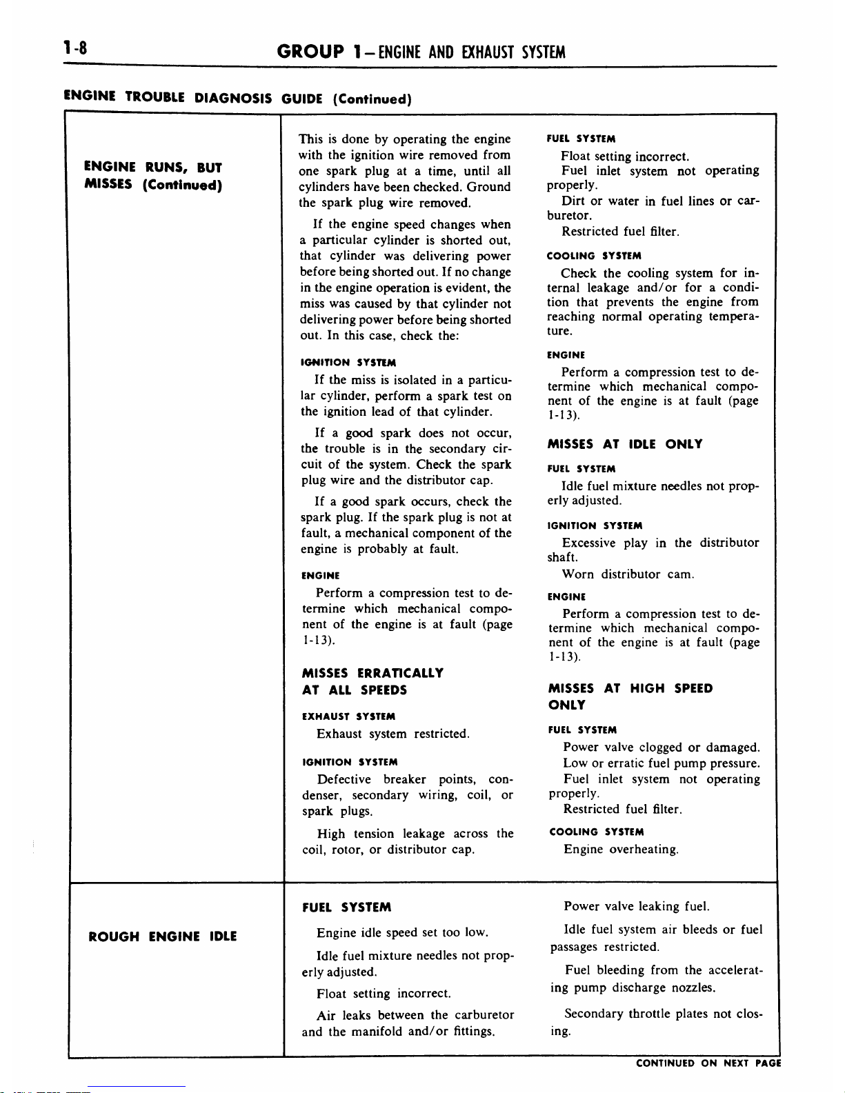
FIG.
12
Positive
Crankcase
Ventilation
Regulator
Valve
of
the
cylinder
head
and
in
the
push
rod
chamber
floor.
POSITIVE
CRANKCASE
VENTILATION
SYSTEM
Ventilating
air
is
drawn
into
the
engine
through
the
breather
cap
by
a
regulator
valve
located
in
the
intake
manifold.
The
valve
regulates
the
amount
of
air
to
meet
changing
oper
ating
conditions.
The
airisreturned
to
the
intake
manifold
through
an
exhaust
tube
which
extends
from
the
crankcase ventilation
outlet
at
the
rear
of
the
intake
manifold
to
a
spring-loaded
regulator
valve
in
stalled
in
the
intake
manifold
(Fig.
11).
When
the
engine
is
shut
off,
the
tt^^ft*
spring
forces
the
valve
off
its
seat.
This
closes
off
the
inlet
to
the
valve
housing.
During
idle,
intake
manifold
vac
uum
is
high.
The
high
vacuum
over
comes
the
tension
of
the
spring
pres
sure
and
seats
the
valve
(Fig.
12).
With
the
valve
in
this
position,
all
the
ventilating
air
passes
through
a
calibrated
orifice
in
the
valve.
With
the
valve
seated
there
is
minimum
ventilation.
As
engine
speed
increases
and
manifold
vacuum
decreases,
the
spring
forces
the
valve
off
its
seat
and
to
the
full
open
position.
This
increases
the
flow
of
ventilating
air.
From
the
breather
cap,
the
air
flows
into
the
front
section
of
the
valve
push
rod
chamber
where
there
are
few
contaminating
vapors.
Here,
&&%*
A1490-A
FIG.
11
Positive
Crankcase
Ventilation
System

16
GROUP
1-
ENGINE
AND
EXHAUST
SYSTEM
the
incoming
air
has
a
chance
to
warm
up
before
contacting
contam
inating
vapors
originating
in
the
crankcase.
Warm
ventilating
air
mini
mizes
the
formation
of
crankcase
sludge.
The
ventilating
air
is
directed
by
a
baffle,
located
on
the
underside
of
the
intake
manifold,
upward
into
the
front
of
both
valve
rocker
arm
chambers.
The
baffle
also
directs
air
to
the
front
of
the
lower
crankcase
and
into
the
timing
chain
chamber.
Air
from
the
valve
rocker
arm
chamber
and
from
the
crankcase
flows
into
the
rear
of
the
valve
push
rod
chamber.
All
air
is
then
drawn
through
the
regulator
valve
and
is
discharged
into
the
intake
manifold.
COOUNO
SYSTEM
The
coolant
is
drawn
from
the
bottom
of
the
radiator
by
the
water
pump
which
delivers
the
coolant
to
the
cylinder
block
(Fig.
13).
The
coolant
travels
through
cored
passages
to
cool
the
entire
length
of
each
cylinder
wall.
Upon
reaching
the
rear
of
the
cylinder
block,
the
coolant
is
directed
upward
into
the
cylinder
heads
where
it
cools
the
combustion
chambers,
valves,
and
valve
seats
on
its
return
to
the
front
of
the
engine.
TO
RADIATOR
SUPPLY
TANK
FIG.
13
Cooling
System
The
coolant
from
each
cylinder
head
flows
through
the
water
pas
sages
in
the
intake
manifold
and
past
the
water
thermostat,
if
it
is
open,
into
the
radiator
supply
tank.
A1249-B
If
the
thermostat
is
closed,
a
small
portion
of
the
coolant
is
returned
to
the
water
pump
for
recirculation.
The
entire
system
is
pressurized
to
13-15
psi.
ENGINE
TROUBLE
DIAGNOSIS
Engine
performance
complaints
usually
fall
under
one
of
the
basic
headings
listed
in
the
"Engine
Trouble
Diagnosis
Guide."
When
a
particular
trouble
can
not
be
traced
to
a
definite
cause
by
a
simple
check,
the
possible
items
that
could
be
at
fault
are
listed
in
the
order
of
their
probable occurrence.
Check
the
items
in
the
order
listed.
For
example,
under
Poor
Acceleration,
the
ignition
system
is
listed
as
a
probable
cause
of
the
trouble.
All
the
ignition
system
items
that
affect
acceleration
are
listed.
Check
all
these
items
before
proceeding
to
the
next
probable
cause.
ENGINE
TROUBLE
DIAGNOSIS
GUIDE
ENGINE
WILL
NOT
CRANK
The
cause
of
this
trouble
is
usually
starter.
If
the
engine
cranks,
it
indi-
in
the
starting
system
(Part
10-2).
cates
that
water
is
leaking
into
the
If
the
starting
system
is
not
at
fault,
cylinders.
Remove
the
cylinder
check
for
a
hydrostatic
lock
or
a
head(s)
and
inspect
the
gaskets(s)
seized
engine
as
follows:
and/
or
head(s)
for
cracks.
Examine
Remove
the
spark
plugs,
then
at-
the
cylinder
block
for
cracks.
tempt
to
crank
the
engine
with
the
ENGINE
CRANKS
NORMALLY,
BUT
WILL
NOT
START
-
Check
the
fuel
supply.
If
there
is
fault
perform
the
following
test:
sufficient
fuel
in
the
tank,
the
cause
Disconnect
a
spark
plug
wire.
of
the
trouble
probably
lies
in
either
Check
the
spark
intensity
at
the
end
the
ignition
or
the
fuel
system.
of
the
wire
by
installing
a
terminal
To
determine
which
system
is
at
adapter
in
the
terminal
of
the
wire
CONTINUED
ON
NEXT
PAGE
PART
1-1
-ENGINE
1-7
ENGINE
TROUBLE
DIAGNOSIS
GUIDE
(Continued)
ENGINE
CRANKS
NORMALLY,
BUT
WILL
NOT
START
(Continued)
to
be
checked.
Hold
the
adapter
ap
proximately
%e
inch
from
the
exhaust
manifold
and
crank
the
engine.
IF
THERE
IS
NO
SPARK
OR
A
WEAK
SPARK
AT
THE
SPARK
PLUGS
The
cause
of
the
trouble
is
in
the
ignition
system.
To
determine
if
the
cause
of
the
trouble
is
in
the
primary
or
the
secondary
circuit,
remove
the
coil
high
tension
lead
from
the
top
of
the
distributor
and
hold
it
approximately
Vie
inch
from
the
cylinder
head.
With
the
ignition
on,
crank
the
engine
and
check
for
a
spark.
If
the
spark
at
the
coil
high
ten
sion
lead
is
good,
the
cause
of
the
trouble
is
probably
in
the
distributor
cap
or
rotor.
If
there
is
no
spark
or
a
weak
spark
at
the
coil
high
tension
lead,
the
cause
of
the
trouble
is
probably
in
the
primary
circuit,
coil
to
dis
tributor
high
tension
lead,
or
the
coil.
IF
THERE
IS
A
GOOD
SPARK
AT
THE
SPARK
PLUGS
Check
the
spark
plugs.
If
the
spark
plugs
are
not
at
fault,
check
the
fol
lowing
items:
AUTOMATIC
CHOKE
Check
the
position
of
the
choke
plate.
If
the
engine
is
hot,
the
plate
should
be
open.
If
the
plate
is
not
open,
the
engine
will
load
up
due
to
the
excessively
rich mixture
and
will
not
start.
If
the
engine
is
cold,
the
plate
should
be
closed.
If
the
plate
is
not
operating
properly,
check
the
fol
lowing
items:
The
choke
linkage
for
binding.
The
fast
idle
cam
for
binding.
Thermostatic
spring
housing
ad
justment.
FUEL
SUPPLY
AT
THE
CARBURETOR
Work
the
throttle
by
hand
several
times.
Each
time
the
throttle
is
ac
tuated,
fuel
should
spurt
from
the
accelerating
pump
discharge
nozzles.
If
fuel
is
discharged
by
the
ac
celerating
pump,
the
engine
is
prob
ably
flooded,
or
there
is
water
in
the
fuel
system,
or
an
engine
me
chanical
item
is
at
fault.
If
fuel
is
not
discharged
by
the
accelerating
pump,
disconnect
the
carburetor
fuel
inlet
line
at
the
carburetor.
Use
a
suitable
container
to
catch
the
fuel.
Crank
the
en
gine
to
see
if
fuel
is
reaching
the
carburetor.
If
fuel
is
not
reaching
the
carbu
retor,
check:
The
fuel
filter.
The
fuel
pump.
The
carburetor
fuel
inlet
line
for
obstructions.
The
fuel
pump
flexible
inlet
line
for
a
collapsed
condition.
The
fuel
tank
line
for
obstruc
tions.
The
fuel
tank
vent.
If
fuel
is
reaching
the
carburetor,
check:
The
fuel
inlet
system
including
the
fuel
inlet
needle
and
seat
as
sembly,
and
the
float
assembly.
ENGINE
STARTS,
BUT
FAILS
TO
KEEP
RUNNING
FUEL
SYSTEM
Idle
fuel
mixture
needles
not
prop
erly
adjusted.
Engine
idle
speed
set
too
low.
The
choke
not
operating
properly.
Float
setting
incorrect.
Fuel
inlet
system
not
operating
properly.
Dirt
or
water
in
fuel
lines
or
in
the
fuel
filter.
Carburetor
icing.
Fuel
pump
defective.
Dirt
in
the
carburetor,
not
allowing
fuel
to
enter
or
be
discharged
from
the
idle
system.
IGNITION
SYSTEM
Leakage
in
the
high
tension
wiring.
ENGINE
RUNS,
BUT
MISSES
Determine
if
the
miss
is
steady
or
erratic
and
at
what
speed
the
miss
occurs
by
operating
the
engine
at
various
speeds
under
load.
MISSES
STEADILY
AT
ALL
SPEEDS
Isolate
the
miss
by
operating
the
engine
with
one
cylinder
not
firing.
CONTINUED
ON
NEXT
PAGE
1-8
GROUP
1-
ENGINE
AND
EXHAUST
SYSTEM
ENGINE
TROUBLE
DIAGNOSIS
GUIDE
(Continued)
This
is
done
by
operating
the
engine
FUEL
SYSTEM
with
the
ignition
wire
removed
from
Float
setting
incorrect.
ENGINE
RUNS,
BUT
one
spark
plug
at
a
time,
until
all
Fuel
inlet
system
not
operating
MISSES
(Continued)
cylinders
have
been
checked.
Ground
properly.
the
spark
plug
wire
removed.
Dirt
or
water
in
fuel
lines
or
car
buretor.
Restricted
fuel
filter.
If
the
engine
speed
changes
when
a
particular
cylinder
is
shorted
out,
that
cylinder
was
delivering
power
COOLING
SYSTEM
before
being
shorted
out.
If
no
change
Check
the
cooling
system
for
in
in
the
engine
operation
is
evident,
the
ternal
leakage
and/
or
for
a
condi
miss
was
caused
by
that
cylinder
not
tion
that
prevents
the
engine
from
delivering
power
before
being
shorted
reaching
normal
operating
tempera
out.
In
this
case,
check
the:
ture.
ENGINE
IGNITION
SYSTEM
If
the
miss
is
isolated
in
a
particu
Perform
a
compression
test
to
de
termine
which
mechanical
compo
lar
cylinder,
perform
a
spark
test
on
nent
of
the
engine
is
at
fault
(page
the
ignition lead
of
that
cylinder.
1-13).
If
a
good
spark
does
not
occur,
the
trouble
is
in
the
secondary
cir
MISSES
AT
IDLE
ONLY
cuit
of
the
system.
Check
the
spark
FUEL
SYSTEM
plug
wire
and
the
distributor
cap.
Idle fuel
mixture
needles
not
prop
If
a
good
spark
occurs,
check
the
erly
adjusted.
spark
plug.
If
the
spark
plug
is
not
at
IGNITION
SYSTEM
fault,
a
mechanical
component
of
the
engine
is
probably
at
fault.
Excessive
play
in
the
distributor
shaft.
ENGINE
Worn
distributor
cam.
Perform
a
compression
test
to
de
ENGINE
termine
which
mechanical
compo
Perform
a
compression
test
to
de
nent
of
the
engine
is
at
fault
(page
termine
which
mechanical
compo
1-13).
nent
of
the
engine
isatfault
(page
1-13).
MISSES
ERRATICALLY
AT
ALL
SPEEDS
MISSES
AT
HIGH
SPEED
ONLY
EXHAUST
SYSTEM
Exhaust
system
restricted.
FUEL
SYSTEM
Power
valve
clogged
or
damaged.
IGNITION
SYSTEM
Low
or
erratic
fuel
pump
pressure.
Defective breaker
points,
con
Fuel
inlet
system
not
operating
denser,
secondary
wiring,
coil,
or
properly.
spark
plugs.
Restricted
fuel
filter.
High
tension
leakage
across
the
COOLING
SYSTEM
coil,
rotor,
or
distributor
cap.
Engine
overheating.
FUEL
SYSTEM
Power
valve
leaking
fuel.
ROUGH
ENGINE
IDLE
Engine
idle
speed
set
too
low.
Idle
fuel
system
air
bleeds
or
fuel
Idle
fuel
mixture
needles
not
prop
passages
restricted.
erly
adjusted.
Fuel
bleeding
from
the
accelerat
Float
setting
incorrect.
ing
pump
discharge
nozzles.
Air
leaks
between
the
carburetor
Secondary
throttle
plates
not
clos
and
the
manifold
and/or
fittings.
ing.
CONTINUED
ON
NEXT
PAGE
PART
1-1
-ENGINE
1-9
ENGINE
TROUBLE
DIAGNOSIS
GUIDE
(Continued)
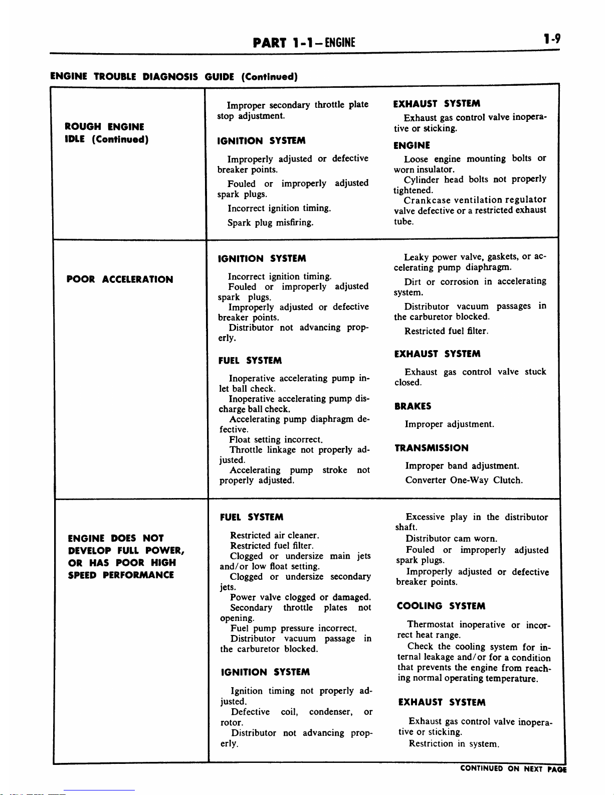
ROUGH
ENGINE
IDLE
(Continued)
Improper
secondary
throttle
plate
EXHAUST
SYSTEM
stop
adjustment.
Exhaust
gas
control
valve
inopera
tive
or
sticking.
IGNITION
SYSTEM
ENGINE
Improperly
adjusted
or
defective
Loose
engine
mounting
bolts
or
breaker
points.
worn
insulator.
Fouled
or
improperly
adjusted
Cylinder
head
bolts
not
properly
spark
plugs.
tightened.
r
r
Crankcase
ventilation
regulator
Incorrect
ignition
timing.
vajve
defective
or
a
restricted
exhaust
Spark
plug
misfiring.
tube.
POOR
ACCELERATION
IGNITION
SYSTEM
Leaky
power
valve,
gaskets,
or
ac
celerating
pump
diaphragm.
Incorrect
ignition
timing.
_.
i*:-
_
,
,
6
.
.
f
..
..
Dirt
or
corrosion
in
accelerating
Fouled
or
improperly
adjusted
spark
plugs.
^
Improperly
adjusted
or
defective
Distributor
vacuum
passages
in
breaker
points.
the
carburetor
blocked.
Distributor
not
advancing
prop-
Restricted
fuel
filter.
erly.
...
everru
EXHAUST
SYSTEM
FUEL
SYSTEM
Exhaust
gas
control
valve
stuck
Inoperative
accelerating
pump
in-
closed
let
ball
check.
Inoperative
accelerating
pump
dis
charge
ball
check.
BRAKES
PUmP
diaphragm
dC"
Improper
adjustment.
Float
setting
incorrect.
Throttle
linkage
not
properly
ad-
TRANSMISSION
^Accelerating
pump
stroke
not
Improper
band
adjustment.
properly
adjusted.
Converter
One-Way
Clutch.
ENGINE
DOES
NOT
DEVELOP
FULL
POWER,
OR
HAS
POOR
HIGH
SPEED
PERFORMANCE
FUEL
SYSTEM
Excessive
play
in
the
distributor
shaft.
Restricted
air
cleaner.
Distributor
cam
worn.
Restricted
fuel
filter.
Fou,ed
Qr
^^i
adjusted
Clogged
or
undersize
main
jets
k
.
and/
or
low
float
setting.
T
'.
,.
,
.
.
Clogged
or
undersize
secondary
.
ImProPerly
adJust^
or
defective
.
t
breaker
points.
Power
valve
clogged
or
damaged.
Secondary
throttle
plates
not
COOLING
SYSTEM
opening.
Fuel
pump
pressure
incorrect.
Thermostat
inoperative
or
incor-
Distributor
vacuum
passage
in
rect
heat
ran8e-
the
carburetor
blocked.
Check
the
cooling
system
for
in
ternal
leakage
and/or
for
a
condition
IGNITION
SYSTEM
that
Prevents
tne
en8'ne
from
reach
ing
normal
operating
temperature.
Ignition
timing
not
properly
ad
justed.
EXHAUST
SYSTEM
Defective
coil,
condenser,
or
rotor.
Exhaust
gas
control
valve
inopera-
Distributor
not
advancing
prop-
tive
or
sticking.
erly.
Restriction
in
system.
CONTINUED
ON
NEXT
PAGE
1-10
GROUP
1-
ENGINE
AND
EXHAUST
SYSTEM
ENGINE
TROUBLE
DIAGNOSIS
GUIDE
(Continued)
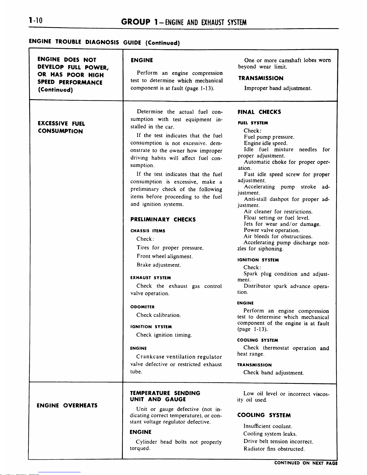
ENGINE
DOES
NOT
ENGINE
One
or
more
camshaft
lobes
worn
DEVELOP
FULL
POWER,
beyond
wear
limit.
OR
HAS
POOR
HIGH
Perform
an
engine
compression
TRANSMISSION
SPEED
PERFORMANCE
test
to
determine
which
mechanical
(Continued)
component
is
at
fault
(page
1-13).
Improper
band
adjustment.
Determine
the
actual
fuel
con
FINAL
CHECKS
sumption
with
test
equipment
in
EXCESSIVE
FUEL
stalled
in
the
car.
FUEL
SYSTEM
CONSUMPTION
Check:
If
the
test
indicates
that
the
fuel
Fuel
pump
pressure.
consumption
is
not
excessive,
dem
Engine
idle
speed.
onstrate
to
the
owner
how
improper
Idle
fuel
mixture
needles
for
driving
habits
will
affect
fuel
con
proper
adjustment.
sumption.
Automatic
choke
for
proper
oper
ation.
If
the
test
indicates
that
the
fuel
Fast
idle
speed
screw
for
proper
consumption
is
excessive,
make
a
adjustment.
preliminary
check
of
the
following
Accelerating
pump
stroke
ad
justment.
items
before
proceeding
to
the
fuel
Anti-stall
dashpot
for
proper
ad
and
ignition
systems.
justment.
Air
cleaner
for
restrictions.
PRELIMINARY
CHECKS
Float
setting
or
fuel
level.
Jets for
wear
and/or
damage.
CHASSIS
ITEMS
Power
valve
operation.
Check:
Air
bleeds
for
obstructions.
Accelerating
pump
discharge
noz
Tires
for
proper
pressure.
zles
for
siphoning.
Front
wheel
alignment.
IGNITION
SYSTEM
Brake
adjustment.
Check:
Spark
plug
condition
and
adjust
EXHAUST
SYSTEM
ment.
Check
the
exhaust
gas
control
Distributor
spark
advance
opera
valve
operation.
tion.
ENGINE
ODOMETER
Perform
an
engine
compression
Check
calibration.
test
to
determine
which
mechanical
IGNITION
SYSTEM
Check
ignition
timing.
component
of
the
engine
is
at
fault
(page
1-13).
COOLING
SYSTEM
ENGINE
Check
thermostat
operation
and
Crankcase
ventilation
regulator
heat
range.
valve
defective
or
restricted
exhaust
TRANSMISSION
tube.
Check
band
adjustment.
TEMPERATURE
SENDING
Low
oil
level
or
incorrect
viscos
UNIT
AND
GAUGE
ity
oil
used.
ENGINE
OVERHEATS
Unit
or
gauge
defective
(not
in
dicating
correct
temperature),
or
con
COOLING
SYSTEM
stant
voltage
regulator
defective.
Insufficient
coolant.
ENGINE
Cooling
system
leaks.
Cylinder
head
bolts
not
properly
Drive
belt
tension
incorrect.
torqued.
Radiator
fins
obstructed.
CONTINUED
ON
NEXT
PAGE
 Loading...