

Ford Thudenbind 1959 Shop Manual

1
FORD
FORD
DIVISION
PORD
MOTOR
COMPANY
SHOP
MAM
J

Copyright © 2009, Forel Publishing Company, LLC, Woodbridge, Virginia
All Rights Reserved. No part of this book may be used or reproduced in any manner whatsoever
without written permission of Forel Publishing Company, LLC. For information write to Forel
Publishing Company, LLC, 3999 Peregrine Ridge Ct., Woodbridge, VA 22192
1959 Ford Thunderbird Shop Manual
EAN: 978-1-60371-009-1
ISBN: 1-60371-009-4
Forel Publishing Company, LLC
3999 Peregrine Ridge Ct.
Woodbridge, VA 22192
Email address: webmaster@ForelPublishing.com
Website: http://www.ForelPublishing.com
This publication contains material that is reproduced and distributed under a license from Ford
Motor Company. No further reproduction or distribution of the Ford Motor Company material is
allowed without the express written permission of Ford Motor Company.
NNoottee ffrroomm tthhee EEddiittoorr
This product was created from the original Ford Motor Company’s publication. Every effort has
been made to use the original scanned images, however, due to the condition of the material;
some pages have been modified to remove imperfections.
Although every effort was made to ensure the accuracy of this book, no representations or
warranties of any kind are made concerning the accuracy, completeness or suitability of the
information, either expressed or implied. As a result, the information contained within this book
should be used as general information only. The author and Forel Publishing Company, LLC
shall have neither liability nor responsibility to any person or entity with respect to any loss or
damage caused, or alleged to be caused, directly or indirectly by the information contained in
this book. Further, the publisher and author are not engaged in rendering legal or other
professional services. If legal, mechanical, electrical, or other expert assistance is required, the
services of a competent professional should be sought.
Disclaimer
THUNDERBIRD
INDEX
IGNITION,
FUEL,
AND
COOLING
SYSTEMS
CLUTCH
AND
MANUAL-SHIFT
TRANSMISSIONS
CRUISE-O-MATIC
TRANSMISSIONS
REAR
AXLE
AND
DRIVE
LINE
WHEELS,
TIRES,
CHASSIS
SUSPENSION,
AND
UNDERBODY
STEERING
BRAKES
SE
RVICE
DEPARTMENT
FORD
DIVISION
FORD
MOTOR
COMPANY
1958
FORD
MOTOR
COMPANY.
DEARBORN.
MICHIGAN
Reprinted
with
Ford
Motor
Company's
Permission
GENERATING
AND
STARTING
SYSTEMS
LIGHTS,
INSTRUMENTS,
AND
ACCESSORIES
BODY
MAINTENANCE
AND
REPAIR
DOORS,
DECK
LID,
AND
FRONT
SHEET
METAL
INTERIOR
TRIM,
SEATS,
AND
WINDOWS
CONVERTIBLE
TOP
MAINTENANCE,
LUBRICATION,
AND
SPECIAL
TOOLS

FOREWORD
This
manual
provides
information
for
the
proper
servicing
of
the
1959
Thunderbird.
The
descriptions
and
specifications
contained
in
this
manual
were
in
effect
at
the
time
the
manual
was
approved
for
printing.
The
Ford
Division
of
Ford
Motor
Company
reserves
the
right
to
discontinue
models
at
any
time,
or
change
specifications
or
design,
without
notice
and
without
incurring
obligation.
SERVICE
DEPARTMENT
FORD
DIVISION
FORD
MOTOR
COMPANY

I
THUNDERBIRD
SHOP
MANUAL
GROUP
I
ENGINES
AND
EXHAUST
SYSTEM
PAGE
PART
1-1
GENERAL
ENGINE
SERVICE
1-2
PART
1
-2
THUNDERBIRD
352
SPECIAL
V-8
1-23
PART
1-3
THUNDERBIRD
430
SPECIAL
V-8
1-48
PART
1-4
EXHAUST
SYSTEM
1-72
PART
1-5
SPECIFICATIONS
1-74
12
PART
1-1
GENERAL
ENGINE
SERVICE
Section
Page
1
Engine
Trouble
Diagnosis.
1-2
2
Tune-Up
1-8
3
Tests
and
Adjustments
(Engine
Installed)
1-9
Camshaft
Lobe
Lift
1-9
Valve
Timing
1-9
Valve
Clearance
1-9
Manifold
Vacuum
Test.
1-10
Compression
Test
1-10
4
Cleaning,
Inspection,
and
Reconditioning
1-11
Intake
Manifold
1-11
Section
Page
Exhaust
Manifold
1-11
Valve
Rocker
Arm
Shaft
Assembly
1-12
Push
Rods
1-12
Cylinder
Heads
1-12
Valves
1-13
Hydraulic
Valve
Lifters.
1-15
Timing
Chain
1-15
Camshaft
and
Bearings.
1-15
Crankshaft
1-15
Connecting
Rods
1-16
Pistons,
Pins,
and
Rings.
1-16
The
service
procedures
in
this
Part
apply
to
both
the
Thunderbird
352
and
430
Special
V-8
engines.
The
cleaning,
inspection,
and
recondition
ing
of
the
various
component
parts
apply
after
the
parts
have
been
re
moved
from
the
engine,
or
in
the
case
of
a
complete
overhaul,
after
the
engine
has
been
disassembled.
For
removal,
disassembly
,
assem
bly,
and
installation
procedures,
refer
to
Part
1-2
or
1-3.
Section
Page
Main
and
Connecting
Rod
Bearings
1-18
Flywheel
Manual-Shift
Transmissions
1-21
Cylinder
Block
1-21
Oil
Pan
and
Oil
Pump
(and
Vacuum
Booster
430
Engine)
1-22
ENGINE
TROUBLE
DIAGNOSIS
Poor
engine
performance
can
be
caused
by
the
need of
a
general
engine
tune-up,
by
gradual
wear
of
engine
parts,
or
by
a
sudden
parts
failure.
A
good
trouble
diagnosis
will
indicate
the
need
of
a
com
plete engine
tune-up,
individual
ad
justments,
part(s)
replacement
or
overhaul,
or
the
need
of
a
complete
engine
overhaul.
Engine
performance
complaints
usually
fall
under
one
of
the
basic
headings
listed
in
the
"Engine
Trouble
Diagnosis
Guide."
In
addition,
the
"Engine
Trouble
Diagnosis
Guide,"
lists
procedures
and
checks
to
be
performed
to
help
isolate
the
cause
of
the
trouble.
When
a
particular
trouble
can
not
be
traced
to
a
definite
cause
by
a
simple
check,
the
possible
items
that
could
be
at
fault
are
listed
in
the
order
of
their
probable occurrence.
Therefore,
in
most
cases,
the
items
should
be
checked
in
the
order
listed.
For
example,
under
Poor
Ac
celeration,
the
ignition
system
is
listed
as
a
probable
cause
of
the
trouble.
All
the
ignition
system
items
that
affect
acceleration
are
listed.
These
items
should
all
be
checked
before
proceeding
to
the
next
probable
cause
listed
in
the
guide.
For
the
checking
procedures
and
corrections
to
be
made
in
the
var
ious
systems,
refer
to
that
part
of
the
manual
which
covers
the
system
in
detail.
For
example,
refer
to
Part
2-1
for
ignition
system
items.
ENGINE
TROUBLE
DIAGNOSIS
GUIDE
ENGINE
WILL
NOT
CRANK
The
cause
of
this
trouble
is
engine
cranks,
it
indicates
that
water
usually
in
the
starting
system.
is
leaking
into
the
cylinders.
Re-
If
the
starting
system
is
not
at
move
the
cylinder
head(s)
and
in-
fault,
check
forahydrostatic
lock
spect
the
gasket(s)
and/or
head(s)
or
a
seized
engine.
Remove
the
for
cracks.
Also
examine
the
cylin-
spark
plugs,
then
attempt
to
crank
der
block for
cracks.
the
engine
with
the
starter.
If
the
ENGINE
CRANKS
NORMALLY,
BUT
WILL
NOT
START
Check
the
fuel
supply.
If
there
is
proper
sized
metal
rod
in
the
in
sufficient
fuel
in
the
tank,
the
cause
sulator
so
that
it
protrudes
from
the
of
the
trouble
probably
lies
in
either
insulator.
With
the
ignition
on
and
the
ignition
or
the
fuel
system.
the
starter
cranking
the
engine,
hold
To
determine
which
system
is
at
the
end
of
the
rod
approximately
fault,
remove
the
ignition
wire
from
3/16
inch from
the
cylinder
block.
one
spark
plug.
Insert
a
piece
of
\
CONTINUED
ON
NEXT
PAGE
PART
1-1
-GENERAL
ENGINE
SERVICE
1-3
ENGINE
TROUBLE
DIAGNOSIS
GUIDE
(Cont.)
ENGINE
CRANKS
NORMALLY,
BUT
WILL
NOT
START
(CONT.)
ENGINE
STARTS,
BUT
FAILS
TO
KEEP
RUNNING
NO
SPARK
OR
A
WEAK
SPARK
AT
THE
SPARK
PLUGS
The
cause
of
the
trouble
is
in
the
ignition
system.
To
determine
if
the
cause
of
the
trouble
is
in
the
primary
or
the
secondary
circuit,
remove
the
coil
high
tension
lead
from
the
top
of
the
distributor
and
hold
it
approxi
mately
3/16
inch
from
the
cylinder
head,
then
with
the
ignition
on
and
the
engine
turning
over,
check
for
a
spark.
If
the
spark
at
the
coil
high
ten
sion
lead
is
good,
the
cause
of
the
trouble
is
probably
in
the
distributor
cap,
rotor,
or
the
spark
plug
wires.
If
there
is
no
spark or
a
weak
spark at
the
coil
high
tension
lead,
the
cause
of
the
trouble
is
probably
in
the
primary
circuit,
coil
to
dis
tributor
high
tension
lead,
or
the
coil.
A
GOOD
SPARK
AT
THE
SPARK
PLUGS
If
the
spark
is
good
at
the
spark
plugs,
check
the
spark
plugs and
the
ignition
timing.
If
the
spark
plugs
or
the
ignition
timing
are
not
at
fault,
check
the
following
items:
FUEL
SYSTEM
Check
the
position
of
the
choke
plate.
If
the
engine
is
warm,
the
plate
should
be
open.
If
the
plate
is
not
open,
the
engine
will
load
up
due
to
the
excessively
rich
mixture
and
will
not
start.
If
the
engine
is
cold,
the
plate
should
be
closed,
if
the
plate
is
not
operating
properly,
check
the
fol
lowing
items:
The
choke
linkage
for
binding.
The
fast
idle
cam
for
binding.
Thermostatic
spring
housing
ad
justment.
Fast
idle
speed
screw
for
proper
adjustment.
Choke
plate
valve
for
proper
op
eration
(Ford
carburetor).
Fuel
Supply
at
Carburetor.
Work
the
throttle
by
hand
several
times.
Each
time
the
throttle
is
actuated
fuel
should
spurt
from
the
acceler
ating
pump
discharge
nozzles.
If
fuel
is
discharged
by
the
ac
celerating
pump,
the
engine
is
prob
ably
flooded,
or
there
is
water
in
the
fuel
system,
or
an
engine
me
chanical
item,
such
as
valves,
is
at
fault.
If
fuel
is
not
discharged
by
the
accelerating
pump,
disconnect
the
carburetor
fuel
inlet
line
at
the
carburetor.
Use
a
suitable
container
to
catch
the
fuel.
Crank
the
en
gine
to
see
if
fuel
is
reaching
the
carburetor.
If
fuel
is
not
reaching
the
carbu
retor,
check:
The
fuel
pump.
The
carburetor
fuel
inlet
line
for
obstructions.
The
flexible
fuel
pump
inlet
line
for
a
collapsed
condition.
The
fuel
tank
line
to
flexible
fuel
line
for
obstructions.
The
fuel
tank
vent.
If
fuel
is
reaching
the
carburetor,
check:
The
fuel
inlet
system
including,
the
fuel
inlet
screen,
the
fuel
inlet
needle
and
seat
assembly,
and
the
float
assembly.
Check
for
dirt
in
the
carburetor,
not
allowing
fuel
to
enter
or
be
dis
charged
from
the
idle
system.
ENGINE
Check
the
valve
timing.
FUEL
SYSTEM
Idle
fuel
mixture
needle(s)
not
properly
adjusted.
Engine
idle
speed
set
too
low.
The
choke
not
operating
properly.
Float
setting
incorrect.
Fuel
inlet
system
not
operating
properly.
Dirt
or
water
in
fuel
lines
or
carburetor.
Carburetor
icing.
Fuel
pump
defective.
IGNITION
SYSTEM
Breaker
points
not
properly
ad
justed.
Defective
spark
plugs.
Open
circuit
at
the
resistor.
Leakage
in
the
high
tension
wiring.
CONTINUED
ON
NEXT
PAGE
14
GROUP
1
-ENGINES
AND
EXHAUST
SYSTEM
ENGINE
TROUBLE
DIAGNOSIS
GUIDE
(Cont.)
ENGJNE
RUNS,
BUT
MISSES
ROUGH
ENGINE
IDLE
Determine
if
the
miss
is
steady
or
erratic
and
at
what
speed
the
miss
occurs
by
operating
the
engine
at
various
speeds
under
load.
MISSES
STEADILY
AT
ALL
SPEEDS
Isolate
the
miss
by
operating
the
engine
with
one
cylinder
not
firing.
This
is
done
by
operating
the
engine
with
the
ignition
wire
removed
from
one
spark
plug
at
a
time,
until
all
cylinders
have
been
checked.
Ground
the
spark
plug
wire
re
moved.
If
the
engine speed
changes
when
a
particular
cylinder
is
shorted
out,
that
cylinder
was
delivering
power
before
being
shorted
out.
If
no
change
in
the
engine
operation
is
evident,
the
miss
was
caused
by
that
cylinder
not
delivering
power
before
being
shorted
out.
Check
the:
IGNITION
SYSTEM
If
the
miss
is
isolated
in
a
par
ticular
cylinder,
perform
a
spark
test
on
the
ignition
lead
of
the
cyl
inder.
If
a
good
spark
does
not
occur,
the
trouble
is
in
the
secondary
cir
cuit
of
the
system,
check
the:
Spark
plug
wire.
Distributor
cap.
If
a
good
spark
occurs,
check
the
spark
plug.
If
the
spark
plug
is
not
at
fault,
a
mechanical
component
of
the
engine
is
probably
at
fault.
ENGINE
Perform
a
compression
test
to
de
termine
which
mechanical
compo
nent
of
the
engine
is
at
fault.
MISSES
ERRATICALLY
AT
ALL
SPEEDS
EXHAUST
SYSTEM
Exhaust
gas
control
valve
inoper
ative
or
sticking
(352
engine).
Exhaust
system
restricted.
IGNITION
SYSTEM
Breaker
points
not
properly
ad
justed.
Defective
breaker
points,
con
denser,
secondary
wiring,
coil,
or
spark
plugs.
High
tension
leakage
across
the
coil,
rotor,
or
distributor
cap.
FUEL
SYSTEM
Choke
not
operating
properly.
Float
setting
incorrect.
Fuel
inlet
system
not
operating
properly.
Dirt
or
water
in
fuel
lines
or
carburetor.
COOLING
SYSTEM
Check
the
cooling
system
for
in
ternal
leakage
and/or
for
a
condi
tion
that
prevents
the
engine
from
reaching
normal
operating
tempera
ture.
ENGINE
Perform
a
compression
test
to
determine
which
mechanical
com
ponent
of
the
engine
is
at
fault.
MISSES
AT
IDLE
ONLY
FUEL
SYSTEM
Idle
fuel
mixture
needles
not
properly
adjusted.
IGNITION
SYSTEM
Defective
coil,
condenser,
breaker
points,
rotor,
ignition
wiring,
or
spark
plugs.
Excessive
play
in
the
distributor
shaft.
Worn
distributor
cam.
VACUUM
BOOSTER
PUMP
Leaking
pump,
lines,
or
fittings.
ENGINE
Perform
a
compression
test
to
determine
which
mechanical
com
ponent
of
the
engine
is
at
fault.
MISSES
AT
HIGH
SPEED
ONLY
FUEL
SYSTEM
Power
valve
clogged
or
damaged
(Ford
carburetor).
Vacumeter
not
operating
properly
(Carter
carburetor).
Low
or
erratic
fuel
pump
pres
sure.
Fuel
inlet
system
not
operating
properly.
COOLING
SYSTEM
Engine
overheating.
FUEL
SYSTEM
Engine
idle
speed
set
too
low.
Idle
fuel
mixture
needle(s)
not
properly
adjusted.
Float
setting
incorrect.
Air
leaks
between
the
carburetor
and
the
manifold
and/or
fittings.
Fuel
leakage
at
the
carburetor
fuel bowl(s).
CONTINUED
ON
NEXT
PAGE
PART
1-1
-GENERAL
ENGINE
SERVICE
1-5
ENGINE
TROUBLE
DIAGNOSIS
GUIDE
(Cont.)
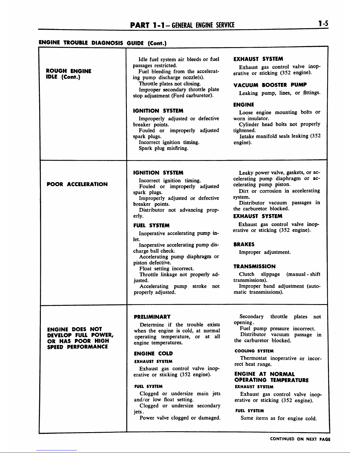
ROUGH
ENGINE
IDLE
(Cont.)
Idle
fuel
system
air
bleeds
or
fuel
EXHAUST
SYSTEM
passages
restricted.
Exhaust
gas
control
valve
inop-
Fuel
bleeding
from
the
accelerat-
erative
or
sticking
(352
engine).
ing
pump
discharge
nozzle(s).
Throttle
plates
not
closing.
VACUUM
BOOSTER
PUMP
Improper
secondary
throttle
plate
,
.
,
*.*.-
stop
adjustment
(Ford
carburetor).
Leak"*
PumP>
,mes>
or
fittm8s-
ENGINE
IGNITION
SYSTEM
Loose
engine
mounting
bolts
or
Improperly
adjusted
or
defective
worn
insulator.
breaker
points.
Cylinder
head
bolts
not
properly
Fouled
or
improperly
adjusted
tightened.
spark
plugs.
Intake
manifold
seals
leaking
(352
Incorrect
ignition
timing.
engine).
Spark
plug
misfiring.
POOR
ACCELERATION
IGNITION
SYSTEM
Leaky
power
valve,
gaskets,
or
ac-
Incorrect
ignition
timing.
celerating
pump
diaphragm
or
ac-
Fouled
or
improperly
adjusted
celerating
pump
piston.
spark
plugs.
Dirt
or
corrosion
in
accelerating
Improperly
adjusted
or
defective
system.
breaker
points.
Distributor
vacuum
passages
in
Distributor
not
advancing
prop-
the
carburetor
blocked.
erly.
EXHAUST
SYSTEM
FUEL
SYSTEM
Exhaust
gas
control
valve
inop-
,
erative or
sticking
(352
engine).
Inoperative
accelerating
pump
in-
&
v
e
let.
Inoperative
accelerating
pump
dis-
BRAKES
charge
ball
check.
Improper
adjustment.
Accelerating
pump
diaphragm
or
piston
defective.
tbammk<iom
Float
setting
incorrect.
iKAnainiaaiuri
Throttle
linkage
not
properly
ad-
Clutch
slippage
(manual
-
shift
justed.
transmissions).
Accelerating
pump
stroke
not
Improper
band
adjustment
(auto-
properly
adjusted.
matic
transmissions).
ENGINE
DOES
NOT
DEVELOP
FULL
POWER,
OR
HAS
POOR
HIGH
SPEED
PERFORMANCE
PRELIMINARY
Secondary
throttle
plates
not
Determine
if
the
trouble
exists
opening.
when
the
engine
is
cold,
at
normal
Fuel
PumP
Pressure
^correct.
operating
temperature,
or
at
all
Distributor
vacuum
passage
in
engine
temperatures.
the
carburetor
blocked.
ENGINE
COLD
COOUNG
SYSTEM
EXHAUST
SYSTEM
Thermostat
inoperative
or
incor-
rect
heat
range.
Exhaust
gas
control
valve
inop
erative
or
sticking
(352
engine).
ENGINE
AT
NORMAL
OPERATING
TEMPERATURE
FUEL
SYSTEM
EXHAUST
SYSTEM
Clogged
or
undersize
main
jets
Exhaust
gas
control
valve
inop-
and/or
low
float
setting.
erative
or
sticking
(352
engine).
Clogged
or
undersize
secondary
jets.
FuEL
SYSTEM
Power
valve
clogged
or
damaged.
Same
items
as
for
engine
cold.
CONTINUED
ON
NEXT
PAGE

1-6
GROUP
1
-ENGINES
AND
EXHAUST
SYSTEM
ENGINE
TROUBLE
DIAGNOSIS
GUIDE
(Cont.)
ALL
ENGINE
TEMPERATURES
ENGINE
IGNITION
SYSTEM
Perform
an
engine
compression
ENGINE
DOES
NOT
DEVELOP
FULL
POWER,
Ignition
timing
not
properly
ad
justed.
Defective
coil,
condenser,
or
test
to
determine
which
mechanical
component
is
at
fault.
OR
HAS
POOR
HIGH
One
or
more
camshaft
lobes
worn
SPEED
PERFORMANCE
(Cont.)
rotor.
beyond
wear
limit.
Distributor
not
advancing
prop
Improper
valve
timing.
erly.
Excessive
play
in
the
distributor
EXHAUST
SYSTEM
shaft.
Restriction
in
system.
Distributor
cam
worn.
Fouled
or
improperly
adjusted
TRANSMISSION
spark
plugs
or
spark
plugs
of
im
Improper
band
adjustment
(auto
proper
heat
range.
matic
transmissions).
Improperly
adjusted
or
defective
breaker
points.
BRAKES
Improper
adjustment.
FUEL
SYSTEM
Restricted
air
cleaner.
TIRES
Same
items
as
for
engine
cold.
Improper
pressure.
Determine
the
actual
fuel
con
Idle
fuel
mixture
needle(s)
for
sumption
with
test
equipment
in
proper
adjustment.
EXCESSIVE
FUEL
stalled
in
the
car.
Automatic
choke
for
proper
op
CONSUMPTION
If
the
test
indicates
that
the
fuel
eration.
consumption
is
not
excessive,
dem
Fast
idle
speed
screw
for
proper
onstrate
to
the
owner
how
improper
adjustment.
driving
habits
will
affect
fuel
con
Accelerating
pump
stroke
ad
sumption.
justment.
If
the
test
indicates
that
the
fuel
Anti-stall
dashpot
for
proper
ad
consumption
is
excessive,
make
a
justment.
preliminary
check
of
the
following
Air
cleaner
for
restrictions.
items
before
proceeding
to
the
fuel
Float
setting
or
fuel
level.
and
ignition
systems.
Jets
for
wear
and/or
damage.
Power
valve
or
Vacumeter
opera
PRELIMINARY
CHECKS
tion.
Air
bleeds
for
obstructions.
CHASSIS
ITEMS
Accelerating
pump
discharge
noz
Check:
zles
for
siphoning.
Tires
for
proper
pressure.
IGNITION
SYSTEM
Front
wheel
alignment.
Check:
Brake
adjustment.
Ignition
timing.
EXHAUST
SYSTEM
Spark
plug
condition
and
adjust
Check
the
exhaust
gas
control
ment.
Distributor
spark
advance
opera
valve
operation
(352
engine).
tion.
ODOMETER
ENGINE
Check
calibration.
Perform
an
engine
compression
test
to
determine
which
mechanical
IGNITION
SYSTEM
component
of
the
engine
isatfault.
Check
ignition
timing.
COOLING
SYSTEM
FJNAL
CHECKS
Check
thermostat
operation
and
heat
range.
FUEL
SYSTEM
Check:
TRANSMISSION
Fuel
pump
pressure.
Check
band
adjustment
(auto
Engine
idle
speed.
matic
transmissions).
CONTINUED
ON
NEXT
PAGE
PART
1-1
-GENERAL
ENGINE
SERVICE
1-7
ENGINE
TROUBLE
DIAGNOSIS
GUIDE
(Cont.)
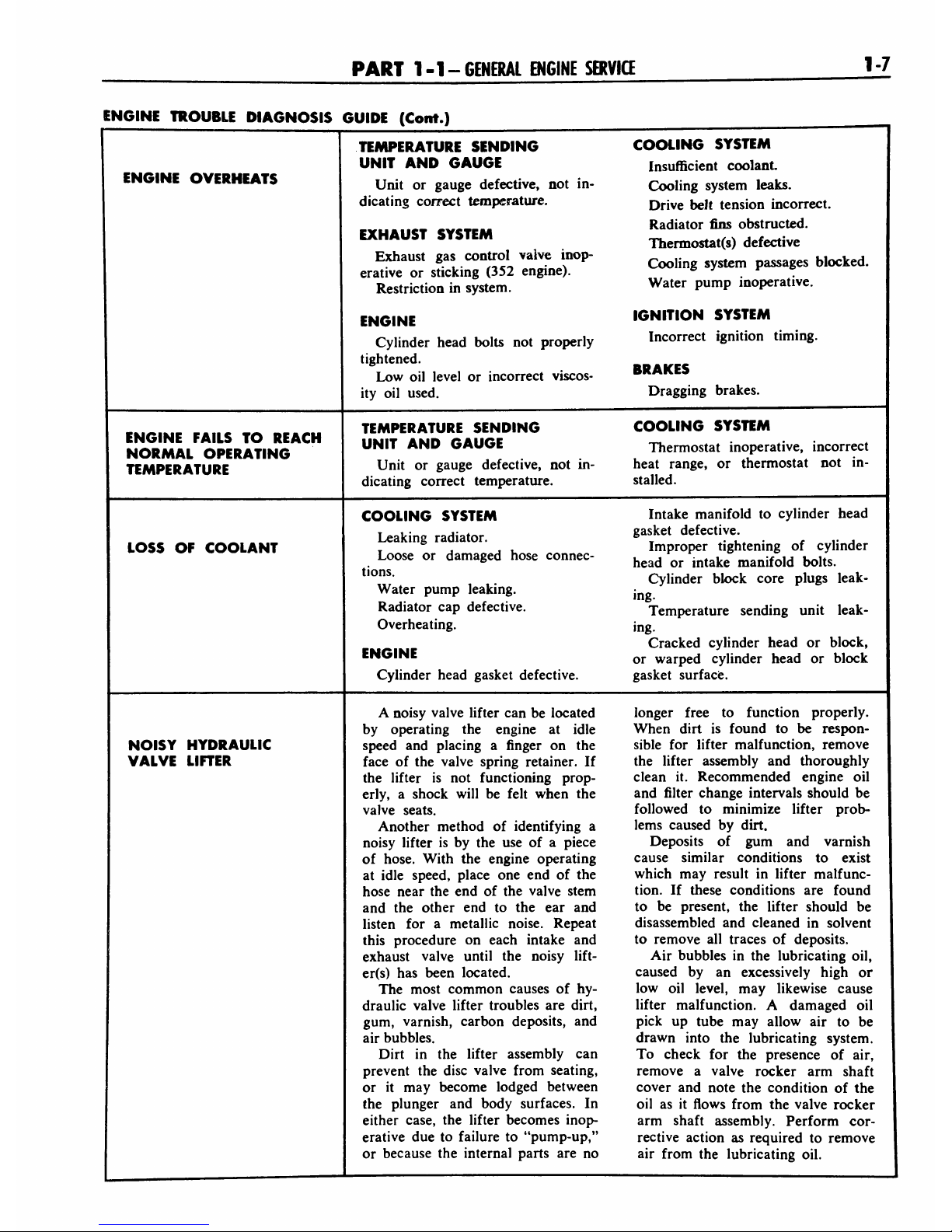
ENGINE
OVERHEATS
TEMPERATURE
SENDING
COOLING
SYSTEM
UNIT
AND
GAUGE
Insufficient
coolant
Unit
or
gauge
defective,
not
in-
Cooling
system
leaks.
dicating
correct
temperature.
Drjve
belt
tension
incorrect.
>~u..e*
.vtfiu
Radiator
fins
obstructed.
EXHAUST
SYSTEM
Therrnostat(s)
defective
Exhaust
gas
control
valvemop-
bhW
erative
or
sticking
(352
engine).
'
.
.
Restriction
in
system.
Water
PumP
^operative.
ENG(NE
IGNITION
SYSTEM
Cylinder
head
bolts
not
properly
Incorrect
ignition
timing.
tightened.
makes
Low
oil
level
or
incorrect
viscos-
""*"
ity
oil
used.
Dragging
brakes.
ENGINE
FAILS
TO
REACH
NORMAL
OPERATING
TEMPERATURE
TEMPERATURE
SENDING
COOLING
SYSTEM
UNIT AND
GAUGE
Thermostat
inoperative,
incorrect
Unit
or
gauge
defective,
not
in-
heat
range,
or
thermostat
not
in
dicating
correct
temperature.
stalled.
LOSS
OF
COOLANT
COOLING
SYSTEM
Intake
manifold
to
cylinder
head
Leaking
radiator.
SasTket
defec^e'
.
f
..
.
,
.
Improper
tightening
of
cylinder
Loose
or
damaged
hose
connec-
head
Qr
mtake
manifold
MtSm
Uom-
Cylinder
block
core
plugs
leak-
Water
pump
leaking.
Radiator
cap
defective.
Temperature
sending
unit
leak-
Overheating.
ing.
Cracked
cylinder
head
or
block,
ENGINE
or
warpe(j
cylinder
head
or
block
j
Cylinder
head
gasket
defective.
gasket
surface.
NOISY
HYDRAULIC
VALVE
LIFTER
A
noisy
valve
lifter
can
be
located
longer
free
to
function
properly.
by
operating
the
engine
at
idle
When
dirt
is
found
to
be
respon-
speed
and
placing
a
finger
on
the
sible
for lifter
malfunction,
remove
face
of
the
valve
spring
retainer.
If
the
lifter
assembly
and
thoroughly
the
lifter
is
not
functioning
prop-
clean
it.
Recommended
engine
oil
erly,
a
shock
will
be
felt
when
the
and
filter
change
intervals
should
be
valve
seats.
followed
to
minimize
lifter
prob-
Another
method
of
identifying
a
lems
caused
by
dirt.
noisy
lifter
is
by
the
use
ofapiece
Deposits
of
gum
and
varnish
of
hose.
With
the
engine
operating
cause
similar
conditions
to
exist
at
idle
speed,
place one
end
of
the
which
may
result
in
lifter
malfunc-
hose
near
the
end
of
the
valve
stem
tion.
If
these
conditions
are
found
and
the
other
end
to
the
ear
and
to
be
present,
the
lifter
should
be
listen
for
a
metallic
noise.
Repeat
disassembled
and
cleaned
in
solvent
this
procedure
on
each
intake
and
to
remove
all
traces
of
deposits.
exhaust
valve
until
the
noisy
lift-
Air
bubbles
in
the
lubricating
oil,
er(s)
has
been
located.
caused
by
an
excessively
high
or
The
most
common
causes
of
hy-
low
oil
level,
may
likewise
cause
draulic
valve
lifter
troubles
are
dirt,
lifter
malfunction.
A
damaged
oil
gum, varnish,
carbon
deposits,
and
pick
up
tube
may
allow
air
to
be
air
bubbles.
drawn
into
the
lubricating
system.
Dirt
in
the
lifter
assembly
can
To
check
for
the
presence
of
air,
prevent
the
disc
valve
from
seating,
remove
a
valve
rocker
arm
shaft
or
it
may
become
lodged
between
cover
and
note
the
condition
of
the
the
plunger
and
body
surfaces.
In
oil
as
it
flows
from
the
valve
rocker
either
case,
the
lifter
becomes
inop-
arm
shaft
assembly.
Perform
cor-
erative
due
to
failure
to
"pump-up,"
rective
action
as
required
to
remove
or
because
the
internal
parts
are
no
air
from
the
lubricating
oil.
1-8
GROUP
1
-ENGINES
AND
EXHAUST
SYSTEM
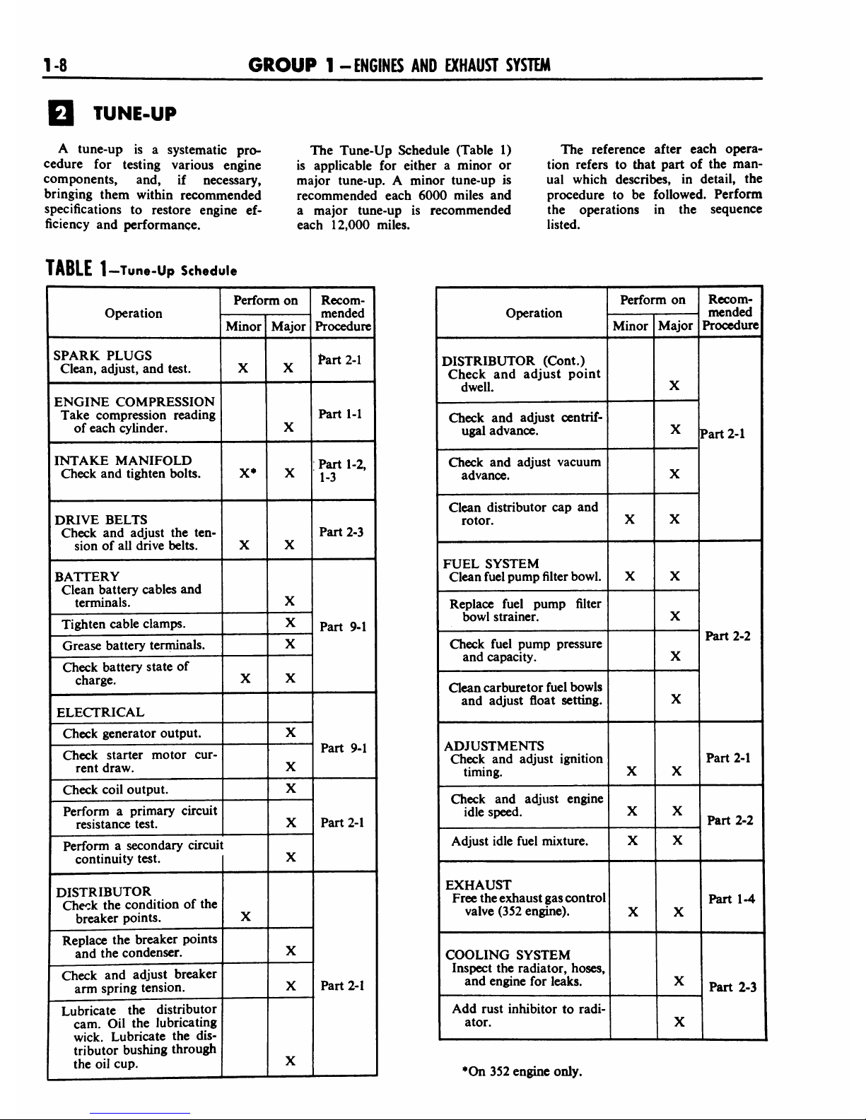
TUNE-UP
A
tune-up
is
a
systematic
pro
cedure
for
testing
various
engine
components,
and,
if
necessary,
bringing
them
within
recommended
specifications
to
restore
engine
ef
ficiency
and
performance.
The
Tune-Up
Schedule
(Table
1)
is
applicable
for
either
a
minor
or
major
tune-up.
A
minor
tune-up
is
recommended
each
6000
miles
and
a
major
tune-up
is
recommended
each
12,000
miles.
The
reference
after
each
opera
tion
refers
to
that
part
of
the
man
ual
which
describes,
in
detail,
the
procedure
to
be
followed.
Perform
the
operations
in
the
sequence
listed.
TABLE
1
-Tune-Up
Schedule
Operation
Perform
on
Recom
mended
Procedure
Minor
Major
SPARK
PLUGS
Clean,
adjust,
and
test.
X
X
Part
2-1
ENGINE
COMPRESSION
Take
compression
reading
of
each
cylinder.
X
Part
1-1
INTAKE
MANIFOLD
Check
and
tighten
bolts.
X*
X
Part
1-2,
1-3
DRIVE
BELTS
Check
and
adjust
the
ten
sion
of
all
drive
belts.
X
X
Part
2-3
BATTERY
Clean
battery
cables
and
terminals.
X
Part
9-1
Tighten
cable
clamps.
X
Grease
battery
terminals.
X
Check
battery
state
of
charge.
X
X
ELECTRICAL
Part
9-1
Check
generator
output.
X
Check
starter
motor
cur
rent
draw.
X
Check
coil
output.
X
Part
2-1
Perform
a
primary
circuit
resistance
test.
X
Perform
a
secondary
circuit
continuity
test.
t
X
DISTRIBUTOR
Check
the
condition
of
the
breaker
points.
X
Part
2-1
Replace
the
breaker
points
and
the
condenser.
X
Check
and
adjust
breaker
arm
spring
tension.
X
Lubricate
the
distributor
cam.
Oil
the
lubricating
wick.
Lubricate
the
dis
tributor
bushing
through
the
oil
cup.
X
Operation
Perform
on
Recom
mended
Procedure
Minor
Major
DISTRIBUTOR
(Cont.)
Check
and
adjust
point
dwell.
X
Part
2-1
Check
and
adjust
centrif
ugal
advance.
X
Check
and
adjust
vacuum
advance.
X
Clean
distributor
cap
and
rotor.
X
X
FUEL
SYSTEM
Clean
fuel
pump
filter
bowl.
X
X
Part
2-2
Replace
fuel
pump
filter
bowl
strainer.
X
Check
fuel
pump
pressure
and
capacity.
X
Clean
carburetor
fuel
bowls
and
adjust
float
setting.
X
ADJUSTMENTS
Check
and
adjust
ignition
timing.
X
X
Part
2-1
Check
and
adjust
engine
idle
speed.
X
X
Part
2-2
Adjust
idle
fuel
mixture.
X X
EXHAUST
Free
the
exhaust
gas
control
valve
(352
engine).
X
X
Part
1-4
COOLING
SYSTEM
!
Inspect
the
radiator,
hoses,
and
engine
for
leaks.
X
Part
2-3
Add
rust
inhibitor
to
radi
ator.
X
*On
352
engine only.

PART
1-1
-GENERAL
ENGINE
SERVICE
1-9
TESTS
AND
ADJUSTMENTS
(ENGINE
INSTALLED)
CAMSHAFT
LOBE
LIFT
1.
Remove
the
valve
rocker
arm
shaft
assembly
and
install
a
solid
tappet-type
push
rod
in
the
push
rod
bore
of
the
camshaft
lobe
to
be
checked.
2.
Make
sure
the
push
rod
is
in
the
lifter
push
rod
cup,
then
install
a
dial
indicator
in
such
a
manner
as
to
have
the
actuating
point
of
the
indi
cator
in
the
push
rod
socket
and
in
the
same
plane
as
the
push
rod
move
ment
(Fig.
1).
3.
Rotate
the
crankshaft
slowly
in
the
direction
of
rotation
until
the
lifter
is
on
the
base
circle
of
the
cam
shaft
lobe.
At
this
point,
the
push
rod
will
be
in
its
lowest
position.
Zero
the
dial
indicator,
then
continue
to
rotate
the
damper
slowly
until
the
push
rod
is
in
the
fully
raised
position.
Com
pare
the
total
lift
recorded
on
the
indicator
with
specifications.
4.
Continue
to
rotate
the
crank
shaft
until
the
indicator
reads
zero.
This
is
a
check
on
the
accuracy
of
the
original
indicator
reading.
VALVE
TIMING
The
valve
timing
should
be
checked
when
poor
engine
performance
is
noted
and
all
other
checks,
such
as
carburetion,
ignition
timing,
etc.
fail
to
locate
the
cause
of
the
trouble.
Before
the
valve
timing
is
checked,
check
for
a
bent
timing
pointer.
Bring
the
No.
1
piston
to
T.D.C.
on
the
compression
stroke
and
see
if
the
timing
pointer
is
aligned
with
the
T.D.C.
mark
on
the
damper.
If
the
valve
timing
is
not
within
specifications,
check
the
timing
chain,
camshaft
sprocket,
crankshaft
sprock
et,
camshaft,
and
crankshaft
in
the
order
of
accessibility.
To
check
the
valve
timing
with
the
engine
installed,
proceed
as
follows:
1.
Install
a
quadrant
on
the
crank
shaft
damper.
BE
SURE
TO
PLACE
Indicator
TIP
IN
CENTER
OF
PUSH
ROD
SOCKET
1748-B
FIG.
1
Camshaft
Lobe
Lift
Typical
Remove
the
right
valve
rocker
arm
shaft
assembly
and
remove
the
No.
1
intake
valve
push
rod
(the
second
push
rod)
and
install
a
solid
tappet-
type
push
rod
in
its
place.
2.
Make
sure
the
push
rod
is
in
the
lifter
push
rod
cup,
then
install
a
dial
indicator
in
such
a
manner
as
to
have
the
actuating
point
of
the
in
dicator
in
the
push
rod
socket
and
in
the
same
plane
as
the
push
rod
move
ment
(Fig.
1).
3.
Rotate
the
crankshaft
slowly
in
the
direction
of
rotation
until
the
lifter
is
on
the
base
circle
of
the
cam
shaft
lobe.
At
this
point
the
push
rod
will
be
in
its
lowest
position.
Zero
the
dial
indicator
and
continue
rotat
ing
the
crankshaft
slowly
in
the
direc
tion
of
rotation
until
the
dial
indicator
registers
the
specified
camshaft
lobe
lift (Table
2).
4.
Compare
the
crankshaft
degrees
indicated
on
the
quadrant
with
speci
fications
(Table
2).
After
the
valve
opening
is
checked,
continue
to
ro
tate
the
damper
to
check
the
valve
closing.
VALVE
CLEARANCE
A
0.060-inch
shorter
push
rod
(color
coded
white)
or
a
0.060-inch
longer
push
rod
(color
coded
yel
low)
is
available
for
service
to
pro
vide
a
means
of
compensating
for
dimensional
changes
in
the
valve
mechanism.
Valve
stem
to
valve
rocker
arm
clearance
should
be
0.078-0.218
inch
(352
engine)
or
0.126-0.226
inch
(430
engine)
with
the
hydraulic
lifter
completely
col
lapsed.
Repeated
valve
recondition
ing
operations
(valve
and/or
valve
seat
refacing)
will
decrease
this
clear-
TABLE
2
Valve
Timing
Specifications
Engine
Intake
Valve
Exhaust
Valve
Opens
Closes
Opens
Closes
Crankshaft
Degrees
(BTDC)
Camshaft
Lobe
Lift
(Inch)
Crankshaft
Degrees
(ABDC)
Camshaft
Lobe
Lift
(Inch)
Crankshaft
Degrees
(BBDC)
Camshaft
Lobe
Lift
(Inch)
Crankshaft
Degrees
(ATDC)
Camshaft
Lobe
Lift
(Inch)
352
22
0.002
68
0.005
68
0.002
22
0.005
430
22
0.002
68
0.005
63
0.002
27
0.005
MO
GROUP
1-
ENGINES
AND
EXHAUST
SYSTEM
1883-A
Mb.
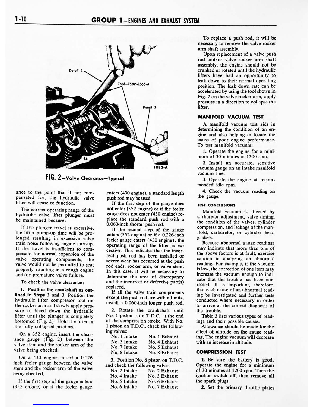
2
Valve
Clearance
Typical
ance
to
the
point
that
if
not
com
pensated
for,
the
hydraulic
valve
lifter
will
cease
to
function.
The
correct
operating
range
of
the
hydraulic
valve
lifter
plunger
must
be
maintained
because:
If
the
plunger
travel
is
excessive,
the
lifter
pump-up
time
will
be
pro
longed
resulting
in
excessive
valve
train
noise
following
engine
start-up.
If
the
travel
is
insufficient
to
com
pensate
for
normal
expansion
of
the
valve
operating
components,
the
valve
would
not
be
permitted
to
seat
properly
resulting
in
a
rough
engine
and/or
premature
valve
failure.
To
check
the
valve
clearance:
1.
Position
the
crankshaft
as
out
lined
in
Steps
2
and
3.
Position
the
hydraulic
lifter
compressor
tool
on
the
rocker
arm
and
slowly
apply
pres
sure
to
bleed
down
the
hydraulic
lifter
until
the
plunger
is
completely
bottomed
(Fig.
2).
Hold
the
lifter
in
the
fully
collapsed
position.
On
a
352
engine,
insert
the
clear
ance
gauge
(Fig.
2)
between
the
valve
stem
and
the
rocker
arm
of
the
valve
being
checked.
On
a
430
engine,
insert
a
0.126
inch
feeler
gauge
between
the
valve
stem
and
the
rocker
arm
of
the
valve
being
checked.
If
the
first
step
of
the
gauge
enters
(352
engine)
or
if
the
feeler
gauge
enters
(430
engine),
a
standard
length
push
rod
may
be
used.
If
the
first
step
of
the
gauge
does
not
enter
(352
engine)
or
if
the
feeler
gauge
does
not
enter
(430
engine)
re
place
the
standard
push
rod
with
a
0.060-inch
shorter
push
rod.
If
the
second
step
of
the
gauge
enters
(352
engine)
or
if
a
0.226-inch
feeler
gauge
enters
(430
engine),
the
operating
range
of
the
lifter
is
ex
cessive.
This
indicates
that
the
incor
rect
push
rod
has
been
installed
or
severe
wear
has
occurred
at
the
push
rod
ends,
rocker
arm,
or
valve
stem.
In
this
case,
it
will
be
necessary
to
determine
the
area
of
discrepancy
and
the
incorrect
or
defective
part(s)
replaced.
If
all
the
valve
train
components
except
the
push
rod
are
within
limits,
install
a
0.060-inch
longer
push
rod.
2.
Rotate
the
crankshaft
until
No.
1
piston
is
on
T.D.C.
at
the
end
of
the
compression
stroke.
With
No.
1
piston
on
T.D.C,
check
the
follow
ing
valves:
No.
1
Intake
No.
1
Exhaust
No.
3
Intake No.
4
Exhaust
No.
7
Intake
No.
5
Exhaust
No.
8
Intake
No.
8
Exhaust
3.
Position
No.
6
piston
on
T.D.C.
and
check
the
following
valves:
No.
2
Intake
No.
2
Exhaust
No.4Intake
No.
3
Exhaust
No.
5
Intake
No.
6
Exhaust
No.6Intake
No.
7
Exhaust
To
replace
a
push
rod,
it
will
be
necessary
to
remove
the
valve
rocker
arm
shaft
assembly.
Upon
replacement
of
a
valve
push
rod
and/
or
valve
rocker
arm
shaft
assembly,
the
engine
should
not
be
cranked
or
rotated
until
the
hydraulic
lifters
have had
an
opportunity
to
leak
down
to
their
normal
operating
position.
The
leak
down
rate
can
be
accelerated
by
using
the
tool
shown
in
Fig.
2
on
the
valve
rocker
arm,
apply
pressure
in
a
direction
to
collapse
the
lifter.
MANIFOLD
VACUUM
TEST
A
manifold
vacuum
test
aids
in
determining
the
condition
of
an
en
gine
and
also
helping
to
locate
the
cause
of
poor
engine
performance.
To
test
manifold
vacuum:
1.
Operate
the
engine
for
a
mini
mum
of
30
minutes
at
1200
rpm.
2.
Install
an
accurate,
sensitive
vacuum
gauge
on
an
intake
manifold
vacuum
line.
3.
Operate
the
engine
at
recom
mended
idle
rpm.
4.
Check
the
vacuum
reading
on
the
gauge.
TEST
CONCLUSIONS
Manifold
vacuum
is
affected
by
carburetor
adjustment,
valve
timing,
the
condition
of
the
valves,
cylinder
compression,
and
leakage
of
the
man
ifold,
carburetor,
or
cylinder
head
gaskets.
Because
abnormal
gauge
readings
may
indicate
that
more
than
one
of
the
above
factors
is
at
fault,
exercise
caution
in
analyzing
an
abnormal
reading.
For
example,
if
the
vacuum
is
low,
the
correction
of
one
item
may
increase
the
vacuum
enough
to
indi
cate
that
the
trouble
has
been
cor
rected.
It
is
important,
therefore,
that
each
cause
of
an
abnormal
read
ing
be
investigated
and
further
tests
conducted
where
necessary
in
order
to
arrive
at
the
correct
diagnosis
of
the
trouble.
Table
3
lists
various
types
of
read
ings
and
their
possible
causes.
Allowance
should
be
made
for
the
effect
of
altitude
on
the
gauge
read
ing.
The
engine
vacuum
will
decrease
with
an
increase
in
altitude.
COMPRESSION
TEST
1.
Be
sure
the
battery
is
good.
Operate
the
engine
for
a
minimum
of
30
minutes
at
1200
rpm.
Turn
the
ignition
switch
off,
then
remove
all
the
spark
plugs.
2.
Set
the
primary
throttle
plates

PART
1-1
-GENERAL
ENGINE
SERVICE
Ml
and
the
choke
plate
in
the
wide
open
position.
3.
Install
a
compression
gauge
in
No.
1
cylinder.
4.
Crank
the
engine
several
times
and
record
the
highest
reading
reg
istered.
Note
the
number
of
compres
sion
strokes
required
to
obtain
the
highest
reading.
5.
Repeat
the
test
on
each
cylin
der,
cranking
the
engine
the
same
number
of
times
for
each
cylinder
as
was
required
to
obtain
the
highest
reading
on
No.
1
cylinder.
TEST
CONCLUSIONS
A
variation
of
20
pounds
from
specified
pressure
is
satisfactory.
However,
the
compression
of
all
cyl
inders
should
be
uniform
within
10
pounds.
A
reading
of
more
than
the
allow
able
tolerance
above
normal
indicates
excessive
deposits
in
the
cylinder.
A
reading
of more
than
the
allow
able
tolerance
below
normal
indicates
leakage
at
the
cylinder
head
gasket,
piston
rings,
or
valves.
A
low
even
compression
in
two
adjacent
cylinders
indicates
a
cylin
der
head
gasket
leak.
This
should
be
checked
before
condemning
the
rings
or
valves.
To
determine
whether
the
rings
or
the
valves
are
at
fault,
squirt
the
equivalent
of
a
tablespoon
of
heavy
TABLE
3
Manifold
Vacuum
Gauge
Readings
Gauge
Reading
Engine
Condition
19-20
inches
(352
engine).
17-18
inches
(430
engine).
Normal.
Low
and
steady.
Loss
of
power
in
all
cylinders
caused
possibly
by
late
ignition
or
valve
timing,
or
loss
of
compression
due
to
leakage
around
the
piston
rings.
Very
low.
Manifold,
carburetor,
or
cylinder
head
gasket
leak.
Needle
fluctuates
steadily
as
speed
increases.
A
partial
or
complete
loss
of
power
in
one
or
more
cylinders
caused
by
a
leaking
valve,
cyl
inder
head
or
intake
manifold
gasket
leak,
a
defect
in
the
ignition
system,
or
a
weak
valve
spring.
Gradual
drop
in
reading
at
engine
idle.
Excessive
back
pressure
in
the
exhaust
system.
Intermittent fluctuation.
An
occasional
loss
of
power
possibly
caused
by
a
defect
in
the
ignition
system
or
a
sticking
valve.
Slow
fluctuation
or
drifting
of
the
needle.
Improper
idle
mixture
adjustment,
carburetor
or
intake
manifold
gasket
leak,
or
possibly
late
valve
timing.
oil
into
the
combustion
chamber,
then
crank
the
engine
to
distribute
the
oil
and repeat
the
compression
test.
The
oil
will
temporarily
seal
leakage
past
the
rings.
If
approximately
the
same
reading
is
obtained,
the
rings
are
satisfactory,
but
the
valves
are
leak
ing.
If
the
compression
has
increased
10
pounds
or
more
over
the
original
reading,
there
is
leakage
past
the
rings.
During
a
compression
test,
if
the
pressure
fails
to
climb
steadily
and
remains
the
same
during
the
first
two
successive
strokes,
but
climbs
higher
on
the
succeeding
strokes,
or
fails
to
climb
during
the
entire
test,
it
in
dicates
a
sticking
or
stuck
valve.
CLEANING,
INSPECTION,
AND
RECONDITIONING
INTAKE
MANIFOLD
Clean
the
manifolds
in
a
suitable
solvent,
then
dry
them
with
com
pressed
air.
On
the
352
engine,
scrape
all
car
bon
deposits
from
the
center
exhaust
passage
below
the
carburetor
heat
riser.
This
carbon
acts
as
an
insu
lator
restricting
the
heating
action
of
the
hot
exhaust
gases.
Inspect
the
manifold
for
cracks,
leaks,
or
other
defects
that
would
make
it
unfit
for
further
service.
Re
place
all
studs
that
are
stripped
or
otherwise
damaged.
Remove
all
fil
ings
and
foreign
matter
that
may
have
entered
the
manifold
as
a
result
of
repairs.
On
the
352
engine,
check
the
baffle
plate
on
the
underside
of
the
mani
fold
for
looseness
and
be
sure
the
maze
screen
is
in
place.
Clean
off
any
varnish
accumulation.
EXHAUST
MANIFOLD
Inspect
the
manifolds
for
cracks,
leaks,
or
other
defects
that
would
make
them
unfit
for further
service.
On
the
right
exhaust
manifold
of
the
352
engine,
clean
out
the
auto
matic
choke
air
heat
chamber
(Fig.
3).
Make
sure
the
air
inlet
and
outlet
holes
are
completely
open
and
the
cover
does
not
leak.
Blow
out
the
AIR
INLET'
1S09-A
FIG.
3
Automatic
Choke
Air
Heat
Chamber
352
Engine
M2
GROUP
1-
ENGINES
AND
EXHAUST
SYSTEM
Runout
Gauge
Holding
fixture'
PUSH
ROD
FIG.
4
Push
Rod
Runout
Typical
1003-A
(D
(3)
CHECK
DIAGONALLY
(|)
CHECK
ACROSS
CENTER
FIG.
5
Cylinder
Head
Flatness
Typical
73S-A
1729-A
FIG.
6
Valve
Seat
Runout
Typical
automatic
choke
air
heat
tube
with
compressed
air.
VALVE
ROCKER
ARM
SHAFT
ASSEMBLY
Clean
all
the
parts
thoroughly.
Make
sure
that
all oil
passages
are
open.
Check
the
clearance
between
each
rocker
arm
and
the
shaft
by
checking
the
I.D.
of
the
rocker
arm
bore
and
the
O.D.
of
the
shaft.
If
the
clear
ance
between
any
rocker
arm
and
the
shaft
exceeds
the
wear
limit,
replace
the
shaft
and/
or
the
rocker
arm.
In
spect
the
shaft
and
the
rocker arm
bore
for
nicks,
scratches,
scores,
or
scuffs.
Dress
up
minor
surface
defects
with
a
hone.
Inspect
the
pad
at
the
valve
end
of
the
rocker
arms
for
a
grooved
radius.
If
the
pad
is
grooved,
replace
the
rocker
arm.
Do
not
attempt
to
true
this
surface
by
grinding.
Check
for
broken
locating
springs.
PUSH
RODS
Check
the
ends
of
the
push
rods
for
nicks,
grooves,
roughness,
or
ex
cessive
wear.
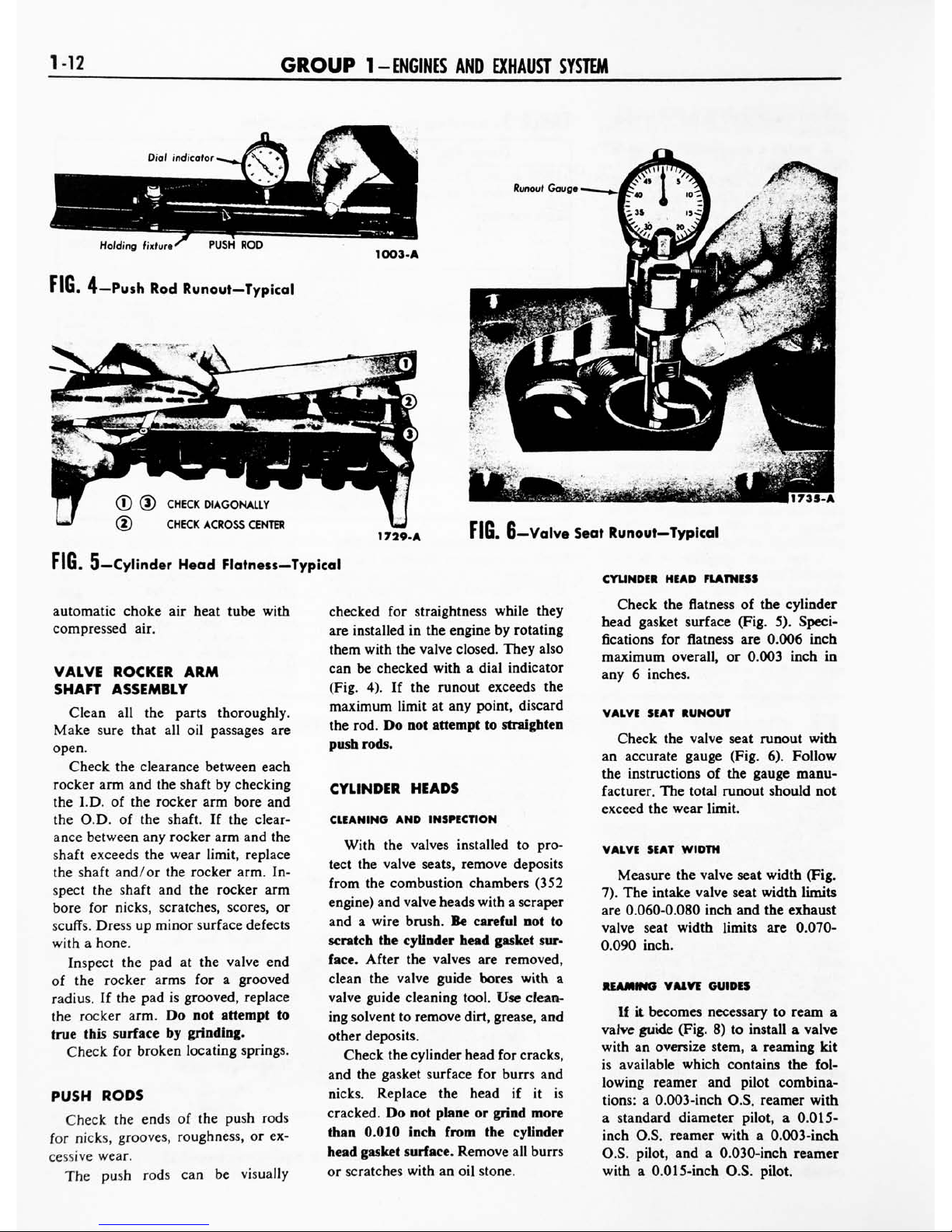
The
push
rods
can
be
visually
checked
for
straightness
while
they
are
installed
in
the
engine
by
rotating
them
with
the
valve
closed.
They
also
can
be
checked
with
a
dial
indicator
(Fig.
4).
If
the
runout
exceeds
the
maximum
limit
at
any
point,
discard
the
rod.
Do
not
attempt
to
straighten
push
rods.
CYLINDER
HEADS
CLEANING
AND INSPECTION
With
the
valves
installed
to
pro
tect
the
valve
seats,
remove
deposits
from
the
combustion
chambers
(352
engine)
and
valve
heads
with
a
scraper
and
a
wire
brush.
Be
careful
not
to
scratch
the
cylinder
head
gasket
sur
face.
After
the
valves
are
removed,
clean
the
valve
guide
bores
with
a
valve
guide
cleaning
tool.
Use
clean
ing
solvent
to
remove
dirt,
grease,
and
other
deposits.
Check
the
cylinder
head
for
cracks,
and
the
gasket
surface
for
burrs
and
nicks.
Replace
the
head
if
it
is
cracked.
Do
not
plane
or
grind
more
than
0.010
inch
from
the
cylinder
head
gasket
surface.
Remove
all
burrs
or
scratches
with an
oil
stone.
CYLINDER
HEAD
FLATNESS
Check
the
flatness
of
the
cylinder
head
gasket
surface
(Fig.
5).
Speci
fications
for
flatness
are
0.006
inch
maximum
overall,
or
0.003
inch
in
any
6
inches.
VALVE
SEAT
RUNOUT
Check
the
valve
seat
runout
with
an
accurate
gauge
(Fig.
6).
Follow
the
instructions
of
the
gauge
manu
facturer.
The
total
runout
should
not
exceed
the
wear
limit.
VALVE
SEAT
WIDTH
Measure
the
valve
seat
width
(Fig.
7).
The
intake
valve
seat
width
limits
are
0.060-0.080
inch
and
the
exhaust
valve
seat
width
limits
are
0.070-
0.090
inch.
REAMING
VALVE
GUIDES
If
it
becomes
necessary
to
ream
a
valve
guide
(Fig.
8)
to
install
a
valve
with
an
oversize
stem,
a
reaming
kit
is
available
which
contains
the
fol
lowing
reamer
and pilot
combina
tions:
a
0.003-inch
O.S.
reamer
with
a
standard
diameter
pilot,
a
0.015-
inch
O.S.
reamer
with
a
0.003-inch
O.S.
pilot,
and
a
0.030-inch
reamer
with
a
0.015-inch
O.S.
pilot.
 Loading...