

Page 1
FORD MONDEO Owner's Manual
Page 2

The information contained in this publication was correct at the time of going to print. In the interest of
continuous development, we reserve the right to change specifications, design or equipment at any time
without notice or obligation. No part of this publication may be reproduced, transmitted, stored in a
retrieval system or translated into any language in any form by any means without our written permission.
Errors and omissions excepted.
© Ford Motor Company 2011
All rights reserved.
Part Number: CG3536en 10/2011 20110816142247
Page 3

Introduction
About This Manual...........................................7
Symbols Glossary.............................................7
Parts and Accessories.....................................7
At a Glance
At a Glance.........................................................11
Child Safety
Child Seats........................................................22
Booster Seats..................................................23
Child Seat Positioning..................................24
ISOFIX Anchor Points...................................26
Child Safety Locks..........................................27
Occupant protection
Principle of Operation..................................29
Fastening the seat belts...............................31
Seat belt height adjustment.......................31
Seat belt reminder.........................................32
Using seat belts during pregnancy..........32
Disabling the passenger airbag.................32
Keys and Remote Controls
General Information on Radio
Frequencies..................................................34
Programming the remote control............34
Changing the remote control
battery............................................................34
Locks
Locking and Unlocking.................................37
Global Opening and Closing......................39
Keyless Entry...................................................40
Engine immobiliser
Principle of Operation..................................44
Coded keys.......................................................44
Arming the engine immobiliser................44
Disarming the engine immobiliser..........44
Alarm
Principle of Operation..................................45
Arming the alarm...........................................47
Disarming the alarm......................................47
Steering Wheel
Adjusting the Steering Wheel...................48
Audio Control..................................................48
Wipers and Washers
Windscreen Wipers.......................................50
Autowipers.......................................................50
Windscreen Washers.....................................51
Rear Window Wiper and Washers............51
Headlamp Washers.......................................52
Checking the Wiper Blades........................52
Changing the Wiper Blades........................52
Lighting
Lighting Control..............................................54
Daytime Running Lamps.............................55
Autolamps........................................................55
Automatic Main Beam Control.................55
Front Fog Lamps.............................................57
Rear Fog Lamps..............................................57
Adjusting the Headlamps - Vehicles
With: Adaptive Front Lighting/Xenon
Headlamps...................................................57
Headlamp Levelling.......................................57
Adaptive Headlamps...................................58
Hazard Warning Flashers...........................60
Direction Indicators.......................................60
Interior Lamps.................................................60
Removing a Headlamp.................................61
Changing a Bulb.............................................63
Bulb Specification Chart.............................69
Windows and Mirrors
Power Windows...............................................71
1
Table of Contents
Page 4

Exterior Mirrors.................................................73
Electric exterior mirrors................................73
Auto-Dimming Mirror....................................75
Blind Spot Monitor.........................................75
Instrument Cluster
Gauges...............................................................78
Warning Lamps and Indicators................80
Audible Warnings and Indicators.............82
Information Displays
General Information.....................................84
Trip Computer.................................................93
Personalised Settings..................................95
Information Messages..................................97
Climate Control
Principle of Operation................................106
Air Vents..........................................................106
Manual Climate Control.............................107
Automatic Climate Control......................109
Heated Windows and Mirrors....................111
Auxiliary Heater..............................................112
Electric sunroof..............................................116
Seats
Sitting in the Correct Position...................119
Manual Seats..................................................119
Power Seats...................................................120
Head Restraints.............................................122
Rear Seats........................................................122
Heated Seats..................................................123
Ventilated Seats............................................124
Convenience features
Sun Shades.....................................................125
Instrument Lighting Dimmer....................125
Clock..................................................................125
Cigar Lighter....................................................125
Ashtray.............................................................126
Auxiliary Power Points................................126
Cup Holders.....................................................127
Glove Box.........................................................127
Storage compartments..............................127
Map Pockets...................................................128
Memory Function.........................................128
Glasses Holder...............................................129
CD changer.....................................................129
Auxiliary input (AUX IN) socket..............130
USB port..........................................................130
Floor Mats.......................................................130
Starting and Stopping the
Engine
General Information.....................................131
Ignition Switch................................................131
Keyless Starting..............................................131
Steering Wheel Lock....................................133
Starting a Petrol Engine.............................133
Starting a Petrol Engine - E85.................134
Starting a Diesel Engine.............................135
Diesel Particulate Filter..............................135
Switching Off the Engine...........................136
Engine Block Heater....................................136
Start-Stop
Principle of Operation.................................138
Using start-stop............................................138
Eco Mode
Principle of Operation................................140
Using Eco mode............................................140
Fuel and Refuelling
Fuel Quality - Petrol.....................................141
Fuel Quality - E85.........................................141
Fuel Quality - Diesel.....................................141
Catalytic Converter......................................142
2
Table of Contents
Page 5

Fuel filler flap.................................................142
Refuelling........................................................144
Refuelling - E85............................................144
Fuel Consumption.......................................144
Technical Specifications............................144
Transmission
Manual Transmission.................................150
Automatic Transmission...........................150
Brakes
Principle of Operation.................................153
Hints on Driving With Anti-Lock
Brakes...........................................................153
Parking Brake.................................................153
Stability Control
Principle of Operation.................................154
Using Stability Control...............................154
Hill Start Assist
Principle of Operation.................................155
Using hill start assist...................................155
Active suspension
Principle of Operation.................................158
Using active suspension............................158
Parking Aids
Principle of Operation.................................159
Using the Parking Aid..................................159
Rear view camera
Principle of Operation..................................161
Using the Rear View Camera....................161
Cruise Control
Principle of Operation................................164
Using Cruise Control...................................164
Adaptive cruise control
(ACC)
Principle of Operation................................166
Using Adaptive Cruise Control.................167
Forward alert function.................................171
Speed Limiter
Principle of Operation.................................172
Using the speed limiter...............................172
Driver Alert
Principle of Operation.................................174
Using driver alert...........................................174
Lane Departure Warning
Principle of Operation.................................176
Using lane departure warning..................176
Load Carrying
General Information....................................178
Luggage Anchor Points..............................178
Sliding Loadspace Floor.............................179
Rear Under Floor Storage...........................181
Luggage Covers..............................................181
Cargo Nets......................................................182
Roof Racks and Load Carriers.................183
Dog Guard.......................................................183
Load Retaining Fixtures.............................185
Towing
Towing a Trailer..............................................187
Tow Ball............................................................187
Driving Hints
Running-In........................................................191
General Driving Points - Vehicles With:
Sports Suspension...................................191
Cold Weather Precautions.........................191
Driving Through Water.................................191
3
Table of Contents
Page 6

Roadside Emergencies
First Aid Kit......................................................192
Warning Triangle...........................................192
Fuses
Fuse Box Locations......................................193
Changing a Fuse...........................................194
Fuse Specification Chart...........................195
Vehicle recovery
Towing Points...............................................205
Towing the Vehicle on Four Wheels......205
Maintenance
General Information...................................207
Opening and Closing the Bonnet..........207
Under Bonnet Overview - 1.6L
Duratec-16V Ti-VCT (Sigma)............209
Under Bonnet Overview - 1.6L EcoBoost
SCTi (Sigma).............................................210
Under Bonnet Overview - 2.0L
Duratec-HE (MI4)......................................211
Under Bonnet Overview - 2.0L EcoBoost
SCTi (MI4)...................................................212
Under Bonnet Overview - 2.3L
Duratec-HE (MI4).....................................213
Under Bonnet Overview - 1.6L
Duratorq-TDCi (DV) Diesel...................214
Under Bonnet Overview - 2.0L
Duratorq-TDCi (DW) Diesel.................215
Under Bonnet Overview - 2.2L
Duratorq-TDCi (DW) Diesel..................217
Engine Oil Dipstick - 1.6L Duratec-16V
Ti-VCT (Sigma)........................................218
Engine Oil Dipstick - 1.6L EcoBoost SCTi
(Sigma)........................................................218
Engine Oil Dipstick - 2.0L Duratec-HE
(MI4)/2.3L Duratec-HE (MI4).............218
Engine Oil Dipstick - 2.0L EcoBoost SCTi
(MI4).............................................................218
Engine Oil Dipstick - 1.6L Duratorq-TDCi
(DV) Diesel/2.0L Duratorq-TDCi (DW)
Diesel/2.2L Duratorq-TDCi (DW)
Diesel............................................................219
Engine Oil Check...........................................219
Engine Coolant Check................................219
Brake and Clutch Fluid Check.................220
Power Steering Fluid Check.....................220
Washer Fluid Check.....................................221
Technical Specifications............................221
Vehicle Care
Cleaning the Exterior..................................224
Cleaning the Interior...................................224
Repairing Minor Paint Damage...............225
Vehicle battery
Jump-Starting the Vehicle.......................226
Changing the Vehicle Battery..................227
Battery connection points........................227
Wheels and Tyres
General Information...................................228
Changing a Road Wheel...........................228
Tyre Repair Kit...............................................233
Tyre Care..........................................................237
Using Winter Tyres.......................................237
Using Snow Chains.....................................238
Tyre Pressure Monitoring System..........238
Technical Specifications...........................239
Vehicle identification
Vehicle Identification Plate......................243
Vehicle Identification Number................244
Capacities and Specific-
ations
Technical Specifications...........................245
4
Table of Contents
Page 7

Audio introduction
Important audio information..................249
Audio unit overview
Audio unit overview....................................250
Audio system security
Security code.................................................253
Lost security code........................................253
Entering a security code............................253
Incorrect security code..............................253
Audio unit clock and date
displays
Setting the clock and date on the audio
unit................................................................254
Audio unit operation
On/off control...............................................255
Bass/treble control.....................................255
Balance/fade control.................................255
Audio menu control....................................255
Station preset buttons...............................257
Waveband button........................................257
Autostore control........................................258
Traffic information control.......................258
Station tuning control................................259
Audio unit menus
Automatic volume control........................261
Digital signal processing (DSP)..............261
Audio distortion reduction (CLIP)..........261
Alternative frequencies.............................262
Regional mode (REG)................................262
News broadcasts.........................................263
Compact disc player
Loading compact discs.............................264
Track selection.............................................264
Loading the compact disc changer......264
Unloading the compact disc
changer.......................................................265
Compact disc playback............................265
Fast forward/reverse..................................265
Shuffle/random...........................................265
Compact disc track compression.........266
Compact disc track scanning.................266
Ejecting compact discs..............................267
Repeat compact disc tracks....................267
MP3 file playback........................................267
MP3 display options...................................268
Ending compact disc playback..............268
Auxiliary input (AUX IN)
socket
Auxiliary input (AUX IN) socket.............269
Audio troubleshooting
Audio troubleshooting...............................270
Telephone
General Information.....................................271
Telephone setup............................................271
Bluetooth setup............................................272
Telephone controls......................................272
Using the telephone - Vehicles Without:
Navigation System..................................273
Using the telephone - Vehicles With:
Navigation System..................................275
Voice control
Principle of Operation................................278
Using voice control......................................278
Audio unit commands...............................279
Telephone commands..............................288
Navigation system commands..............293
Climate control commands....................293
5
Table of Contents
Page 8

Connectivity
General Information...................................296
Connecting an external device...............297
Connecting an external device - Vehicles
With: Bluetooth........................................297
Using a USB device....................................298
Using an iPod...............................................300
Navigation introduction
Road Safety...................................................304
Navigation system
Getting started.............................................305
Appendices
Type approvals.............................................307
Type approvals.............................................307
Type approvals.............................................307
Type approvals............................................308
Electromagnetic compatibility..............309
6
Table of Contents
Page 9
ABOUT THIS MANUAL
Thank you for choosing Ford. We
recommend that you take some time to
get to know your vehicle by reading this
manual. The more that you know about it,
the greater the safety and pleasure you
will get from driving it.
WARNING
Always drive with due care and
attention when using and operating
the controls and features on your
vehicle.
Note: This manual describes product
features and options available throughout
the range, sometimes even before they are
generally available. It may describe options
not fitted to your vehicle.
Note: Some of the illustrations in this
manual may be used for different models,
so may appear different to your vehicle.
However, the essential information in the
illustrations is always correct.
Note: Always use and operate your vehicle
in line with all applicable laws and
regulations.
Note: Pass on this manual when selling
your vehicle. It is an integral part of the
vehicle.
This vehicle has received the endorsement
of TÜV, the accredited international testing
organisation, for its allergy-friendly
properties.
All materials used in the manufacture of
the interior of this vehicle meet strict
requirements of the TÜV TOXPROOF
Criteria Catalogue for Vehicle Interiors by
TÜV Produkt and Umwelt GmbH and are
designed to minimize the risk of allergic
reactions.
Additionally an efficient pollen filter
protects the passengers against allergen
particles in the outdoor air.
For more information, contact TÜV at
www.tuv.com.
SYMBOLS GLOSSARY
Symbols in this handbook
WARNING
You risk death or serious injury to
yourself and others if you do not
follow the instructions highlighted
by the warning symbol.
CAUTION
You risk damaging your vehicle if you
do not follow the instructions
highlighted by the caution symbol.
Symbols on your vehicle
When you see these symbols, read and
follow the relevant instructions in this
handbook before touching or attempting
adjustment of any kind.
PARTS AND ACCESSORIES
Now you can be sure that your Ford
parts are Ford parts
Your Ford has been built to the highest
standards using high quality Ford Original
Parts. As a result, you can enjoy driving it
for many years.
7
Introduction
Page 10
Should the unexpected occur and a major
part needs replacing, we recommend that
you accept nothing less than Ford Original
Parts.
The use of Ford Original Parts ensures that
your vehicle is repaired to its pre-accident
condition and maintains its maximum
residual value.
Ford Original Parts match Ford's stringent
safety requirements and high standards
of fit, finish and reliability. Quite simply,
they represent the best overall repair value,
including parts and labour costs.
Now it is easier to tell if you have really
been given Ford Original Parts. The Ford
logo is clearly visible on the following parts
if they are Ford Original Parts. If your
vehicle has to be repaired, look for the
clearly visible Ford branding and make sure
that only Ford Original Parts have been
used.
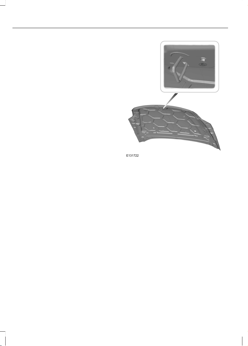
Look for the Ford logo on the
following parts
Sheet metal
• Bonnet
• Doors
• Luggage compartment lid or tailgate
• Wing
E131722
Bumper and radiator grille
• Radiator grille
• Front and rear bumper
8
Introduction
Page 11
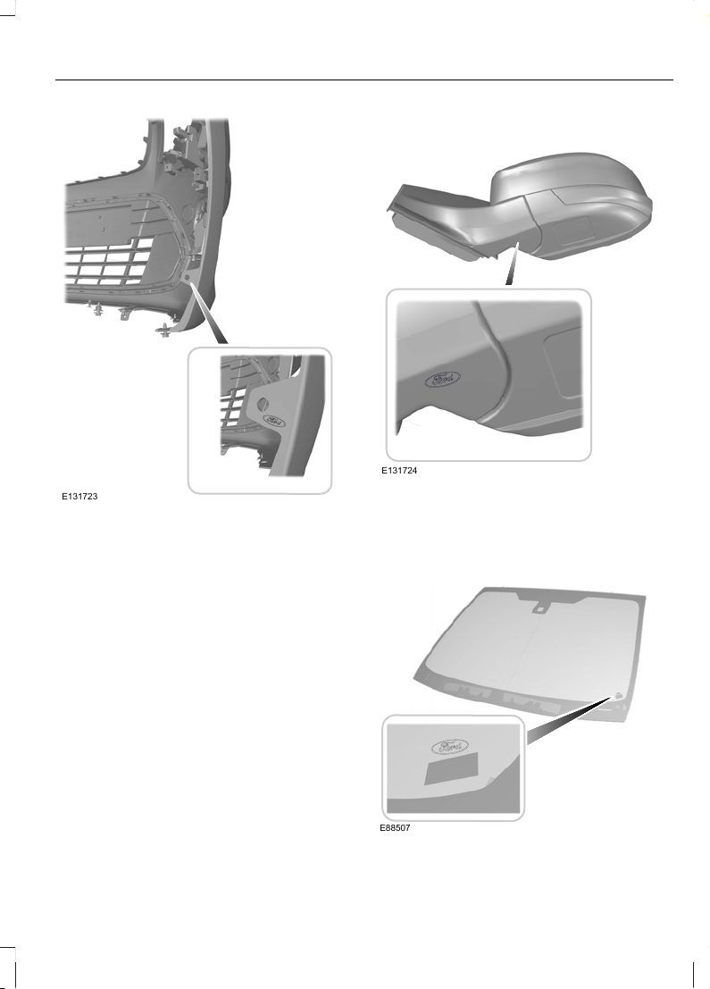
E131723
Exterior mirror
E131724
Glass
• Rear window
• Side glass
• Windscreen
E88507
9
Introduction
Page 12
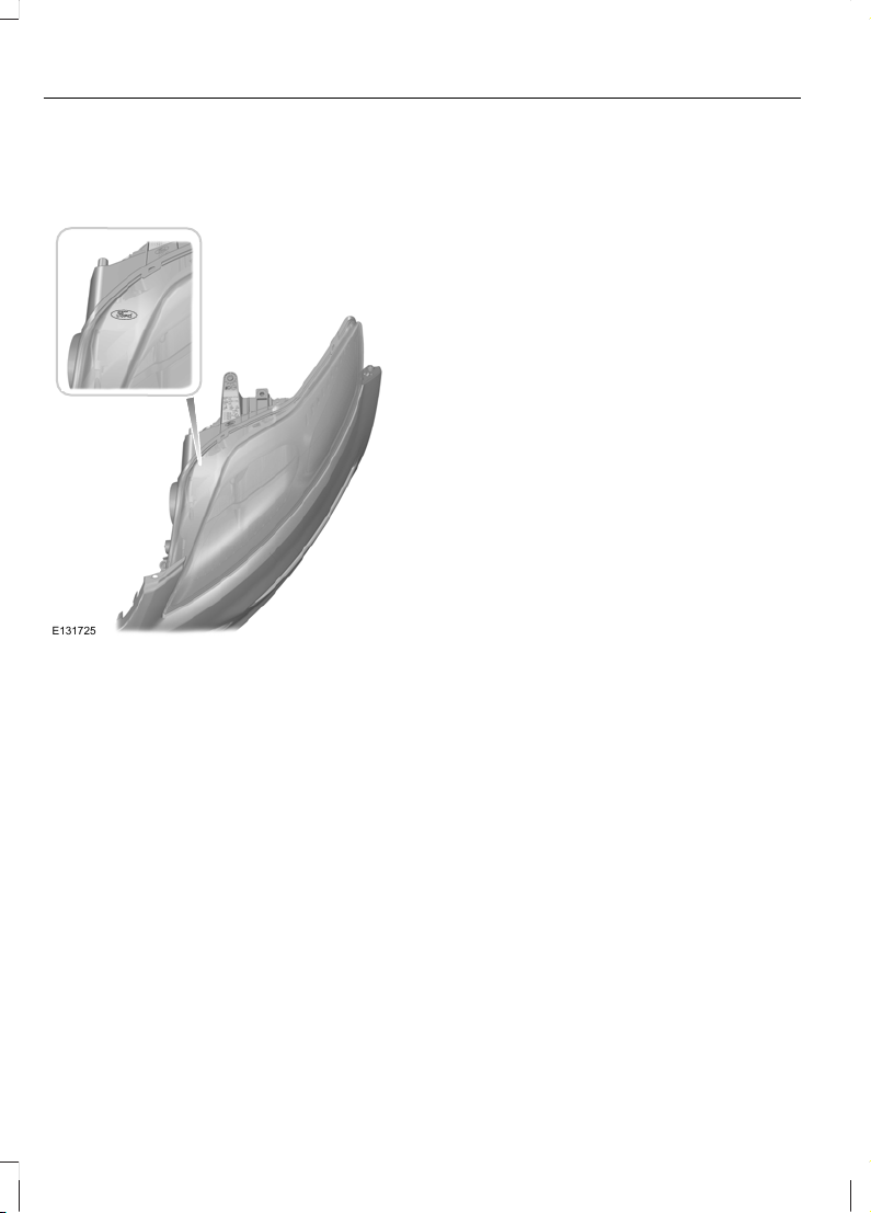
Lighting
• Rear lamps
• Headlamp
E131725
10
Introduction
Page 13
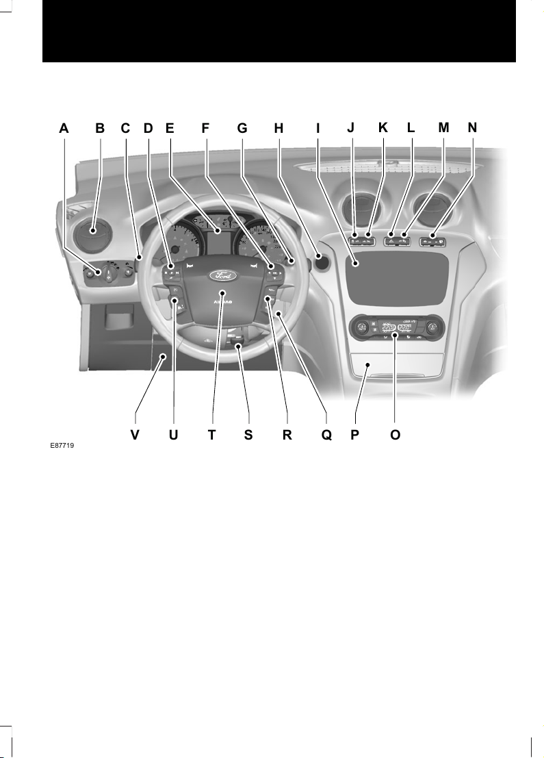
Instrument panel overview - left-hand drive
E87719
A
J K L M N
C DB H IGF
E
P OV U T S R Q
11
At a Glance
Page 14
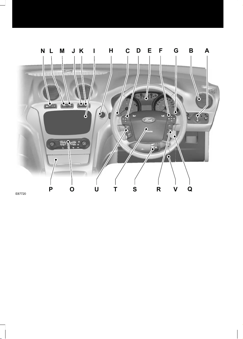
Instrument panel overview - right-hand drive
E87720
E
D
F
G
B
A
M
L
H
CI
O
Q
U
T
S
R
V
P
N J K
Lighting controls. See Lighting Control (page 54).A
Air vents. See Air Vents (page 106).B
Direction indicators. See Direction Indicators (page 60). Telephone control
buttons. See Telephone controls (page 272). Voice control buttons. See Using
voice control (page 278). Lane departure warning control buttons. See Lane
Departure Warning (page 176).
C
Audio controls. See Audio Control (page 48).D
Instrument cluster. See Gauges (page 78).E
Information display controls. See Information Displays (page 84).F
Wiper lever. See Windscreen Wipers (page 50).G
Start button. See Keyless Starting (page 131).H
Audio unit. See Audio unit overview (page 250).I
Navigation unit. See separate handbook.I
12
At a Glance
Page 15

Stability control (ESP) switch. See Using Stability Control (page 154).
Start-stop switch. See Using start-stop (page 138).
J
Parking aid switch. See Using the Parking Aid (page 159).K
Hazard warning flasher switch. See Hazard Warning Flashers (page 60).L
Passenger airbag deactivation warning lamp. See Disabling the passenger
airbag (page 32).
M
Heated windscreen and heated rear window switches. See Heated Windows
and Mirrors (page 111).
N
Climate controls. See Manual Climate Control (page 107). See Automatic
Climate Control (page 109).
O
Cigar lighter. See Cigar Lighter (page 125).P
Ignition switch. See Ignition Switch (page 131).Q
Cruise control and speed limiter switches. See Using Cruise Control (page
164). Adaptive cruise control switches. See Using Adaptive Cruise Control
(page 167). Speed limiter switches. See Using the speed limiter (page 172).
R
Steering wheel adjustment lever. See Adjusting the Steering Wheel (page
48).
S
Horn.T
Cruise control and speed limiter switches. See Using Cruise Control (page
164). Adaptive cruise control switches. See Using Adaptive Cruise Control
(page 167). Speed limiter switches. See Using the speed limiter (page 172).
U
Driver knee airbag. See Principle of Operation (page 29).V
13
At a Glance
Page 16
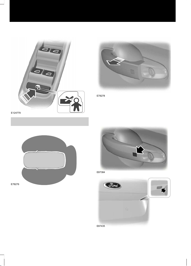
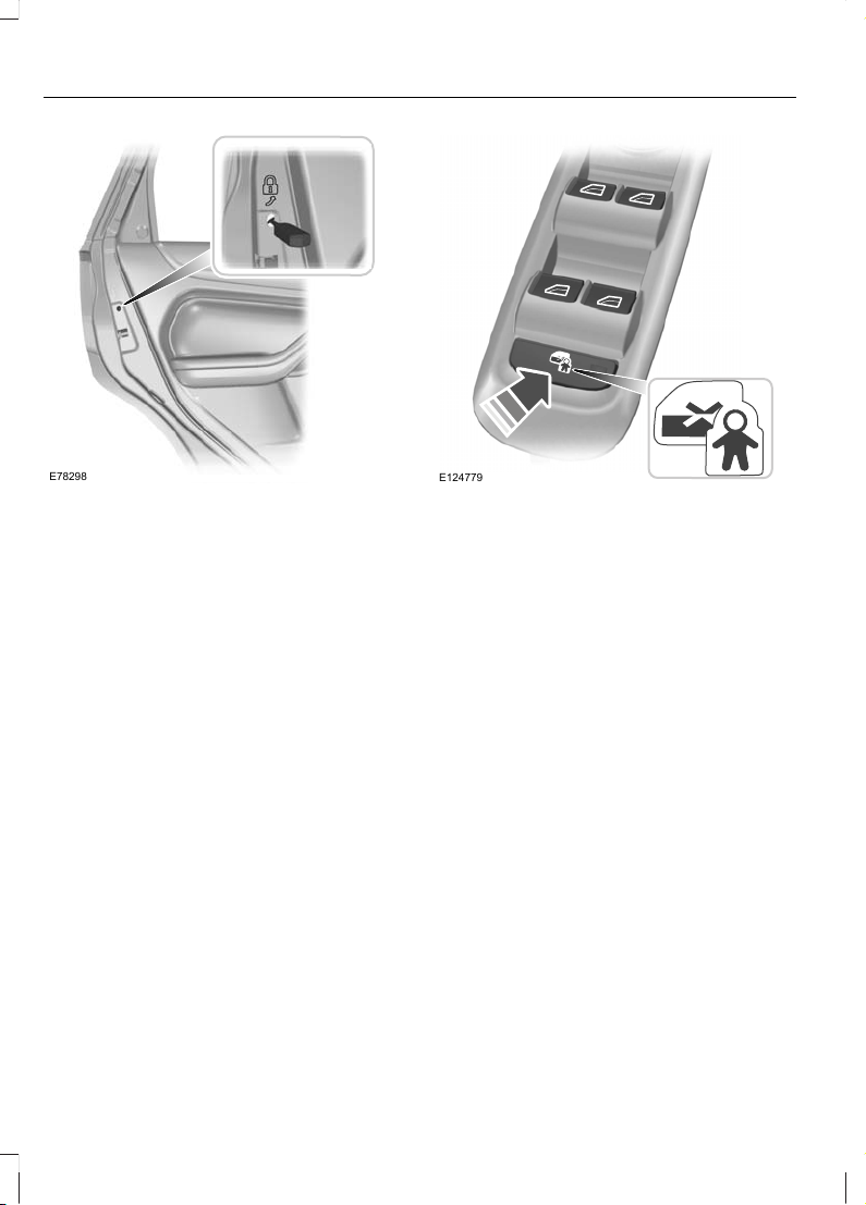
Electric child safety locks
E124779
See Child Safety Locks (page 27).
Keyless entry
E78276
Passive locking and unlocking requires a
valid passive key to be located within one
of the three external detection ranges.
Unlocking the vehicle
E78278
Pull a door handle to unlock all the doors
and the luggage compartment lid and
disarm the alarm.
Locking the vehicle
E87384
E87435
14
At a Glance
Page 17
See Keyless Entry (page 40).
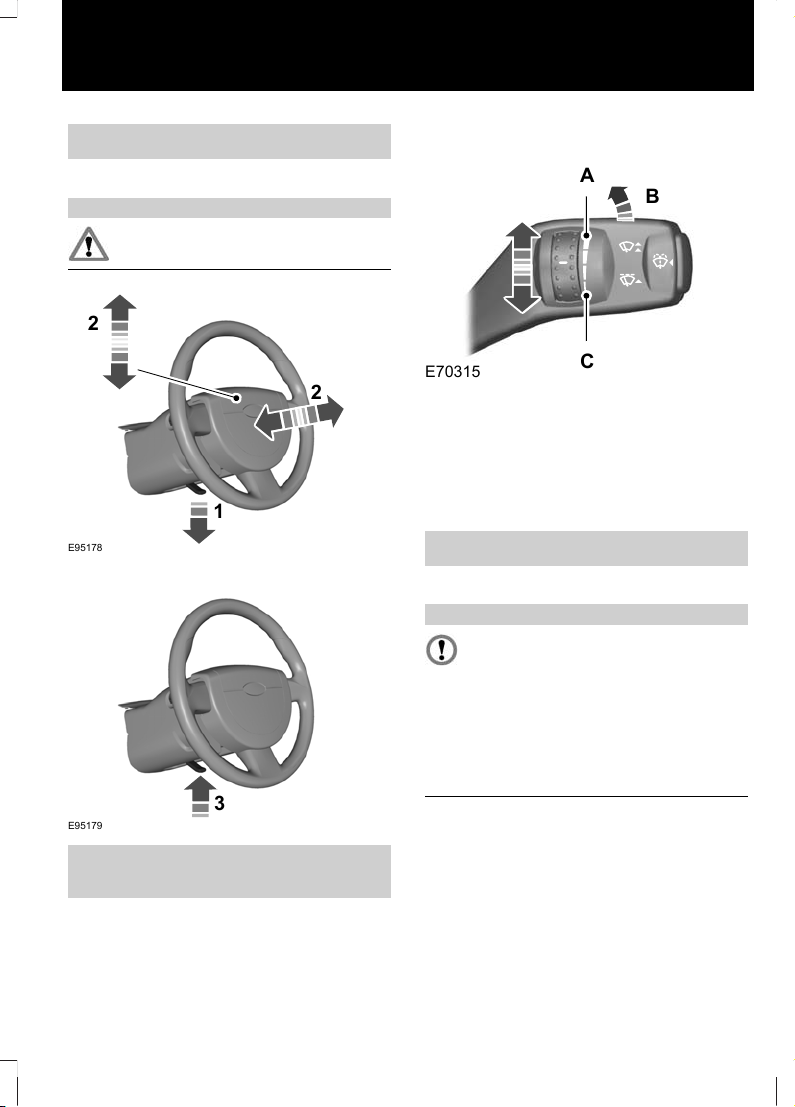
Adjusting the steering wheel
WARNING
Never adjust the steering wheel
when the vehicle is moving.
1
2
2
E95178
3
E95179
See Adjusting the Steering Wheel
(page 48).
Autowipers
E70315
B
A
C
High sensitivityA
OnB
Low sensitivityC
Adjust the sensitivity of the rain sensor
using the rotary control.
See Autowipers (page 50).
Changing the wiper blades
CAUTION
You can use the service position in
winter to provide easier access to the
wiper blades for freeing them from
snow and ice. The windscreen wipers will
return to their normal position as soon as
you switch on the ignition so make sure
that the outside of the windscreen is free
from snow and ice before you switch on
the ignition.
15
At a Glance
Page 18
E85833
A
E75188
Switch off the ignition and move the wiper
lever to position A within three seconds.
Release the lever when the windscreen
wipers have moved to the service position.
See Changing the Wiper Blades (page
52).
Autolamps
E70719
The headlamps will come on and go off
automatically depending on the ambient
light.
See Lighting Control (page 54).
Automatic main beam control
WARNING
The system does not relieve you of
your responsibility to drive with due
care and attention. A manual
override may be necessary if the system
fails to switch the main beam on or off.
The system will automatically switch on
main beam if it is dark enough and no other
traffic is present. If it detects an
approaching vehicle’s headlamps or tail
lamps, or street lighting ahead the system
will switch off main beam before it can
distract other road users. Dipped beams
will remain on.
See Automatic Main Beam Control
(page 55).
16
At a Glance
Page 19
Electric windows
Note: To reduce wind noise or buffeting
when just one window is open, open the
opposite window slightly.
See Power Windows (page 71).
Electric folding mirrors
E72623
See Electric exterior mirrors (page 73).
Reverse mirror dipping
Depending on the selected mirror position,
the relevant exterior mirror will dip
whenever you select reverse gear, giving
you a view of the kerb.
When you first use this feature, the mirrors
will dip to a preset position. You can
programme the degree of dipping.
See Electric exterior mirrors (page 73).
Blind spot information system
(BLIS)
WARNING
Do not use the system as a
replacement for using the side and
rear view mirrors, and looking over
your shoulder before changing lanes. The
system is not a replacement for careful
driving and is only to be used as an aid.
The system displays a yellow indicator
located in the exterior mirrors.
E124736
See Blind Spot Monitor (page 75).
Information displays
E70499
17
At a Glance
Page 20
Use the arrow buttons to navigate through
the menus and press OK to make a
selection.
See Information Displays (page 84).
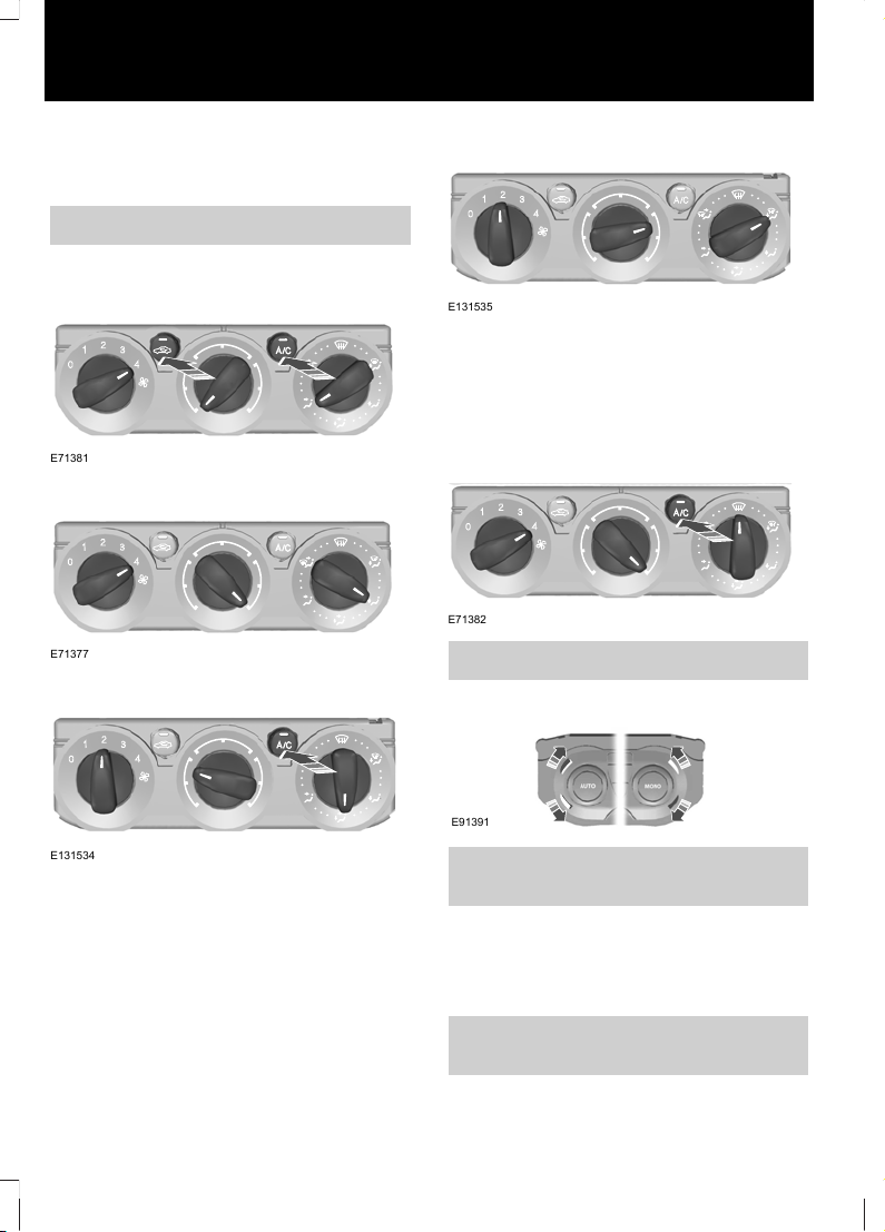
Manual climate control
Cooling the interior quickly
E71381
Heating the interior quickly
E71377
Recommended settings for cooling
E131534
Open the centre and side air vents.
Direct the centre air vents upwards and the
side air vents toward the side windows.
Recommended settings for heating
E131535
Close the centre air vents and open the
side air vents.
Direct the side air vents toward the side
windows.
Defrosting and demisting the
windscreen
E71382
See Manual Climate Control (page 107).
Automatic climate control
E91391
See Automatic Climate Control (page
109).
Engine idle speed after starting
The engine may idle at a higher speed than
normal immediately after starting from
cold.
See Starting and Stopping the Engine
(page 131).
18
At a Glance
Page 21
Keyless starting
E85766
Press the start button.
Stopping the engine when the vehicle
is moving
WARNING
Switching off the engine when the
vehicle is still moving will result in a
loss of brake and steering assistance.
The steering will not be locked, but higher
effort will be required. When the ignition is
switched off some electrical circuits,
warning lamps and indicators may also be
OFF.
Press and hold the start button for two
seconds, or press three times within three
seconds.
See Keyless Starting (page 131).
Diesel particulate filter (DPF)
WARNING
Do not park or idle your vehicle over
dry leaves, dry grass or other
combustible materials. The DPF
regeneration process creates very high
exhaust gas temperatures and the exhaust
will radiate a considerable amount of heat
during and after DPF regeneration, and
after you have switched the engine off.
This is a potential fire hazard.
See Diesel Particulate Filter (page 135).
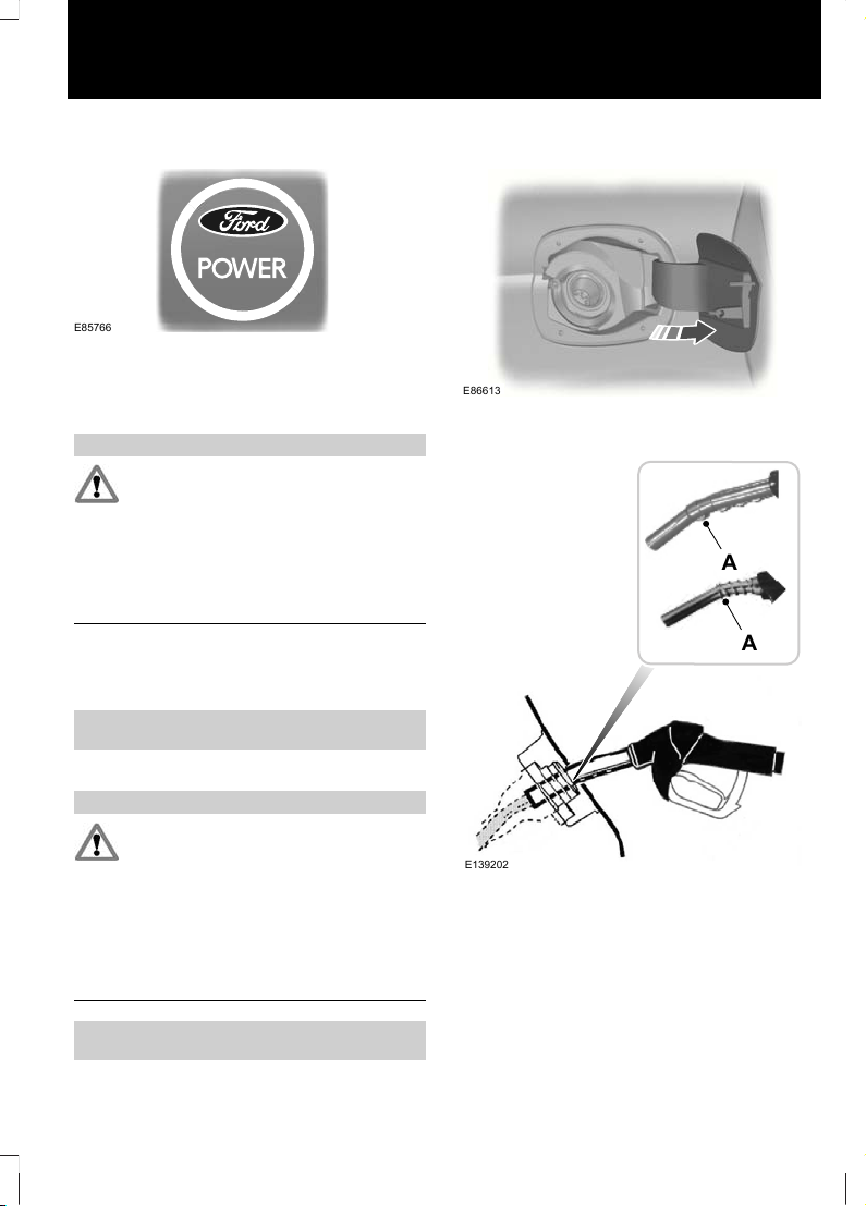
Fuel filler flap
E86613
Press the flap to open it. Open the flap fully
until it engages.
E139202
A
A
Insert the fuel nozzle up to and including
the first notch on the nozzle A. Keep it
resting on the cover of the fuel pipe
opening.
19
At a Glance
Page 22
WARNING
We recommend that you remove the
fuel nozzle slowly to allow any
residual fuel to drain into the fuel
tank. Alternatively you can wait 10 seconds
before removing the fuel nozzle.
E119081
Slightly raise the fuel nozzle to remove it.
See Fuel filler flap (page 142).
Manual transmission
Selecting reverse gear
E99067
On some vehicles it is necessary to raise
the collar whilst selecting reverse gear.
See Manual Transmission (page 150).
Automatic transmission
Note: Do not press the brake pedal when
removing the key from the ignition switch.
Selector lever positions
WARNING
Apply the brakes before moving the
selector lever and keep them applied
until you are ready to move off.
E80836
S
ParkP
ReverseR
NeutralN
DriveD
Manual shifting and sport modeS
See Automatic Transmission (page
150).
Rear view camera
WARNING
The camera does not relieve you of
your responsibility to drive with due
care and attention.
20
At a Glance
Page 23
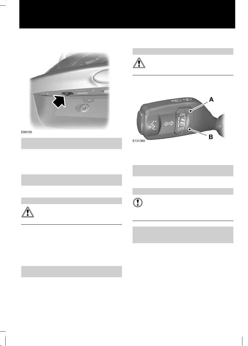
The camera is a visual aid for use when
reversing.
E99105
See Rear view camera (page 161).
Speed limiter
The system allows you to set a speed, to
which the vehicle then becomes limited.
See Speed Limiter (page 172).
Driver alert
WARNING
The system does not relieve you of
your responsibility to drive with due
care and attention.
The system calculates an alertness score
which can be displayed on the information
display. If the system detects that you are
becoming drowsy or there is deterioration
in your driving style then warnings will be
issued.
See Driver Alert (page 174).
Lane departure warning
WARNING
The system does not relieve you of
your responsibility to drive with due
care and attention.
Activate the system using the switches on
the indicator stalk.
E131360
A
B
System onA
System offB
See Lane Departure Warning (page 176).
Towing the vehicle on four wheels
CAUTION
For certain engine and transmission
combinations, it is recommended not
to tow the vehicle with the drive
wheels on the ground.
See Towing the Vehicle on Four
Wheels (page 205).
21
At a Glance
Page 24
CHILD SEATS
E133140
E68916
WARNINGS
Secure children that are less than
150 centimetres (59 inches) tall in a
suitable, approved child restraint, in
the rear seat.
Extreme Hazard! Do not use a
rearward facing child restraint on a
seat protected by an air bag in front
of it!
Read and follow the manufacturer’s
instructions when you are fitting a
child restraint.
Do not modify child restraints in any
way.
Do not hold a child on your lap when
the vehicle is moving.
WARNINGS
Do not leave unattended children in
your vehicle.
If your vehicle has been involved in
an accident, have the child restraints
checked by properly trained
technicians.
Note: Mandatory use of child restraints
varies from country to country.
Only child restraints certified to
ECE-R44.03 (or later) have been tested
and approved for use in your vehicle. A
choice of these are available from your
Dealer.
Child restraints for different mass
groups
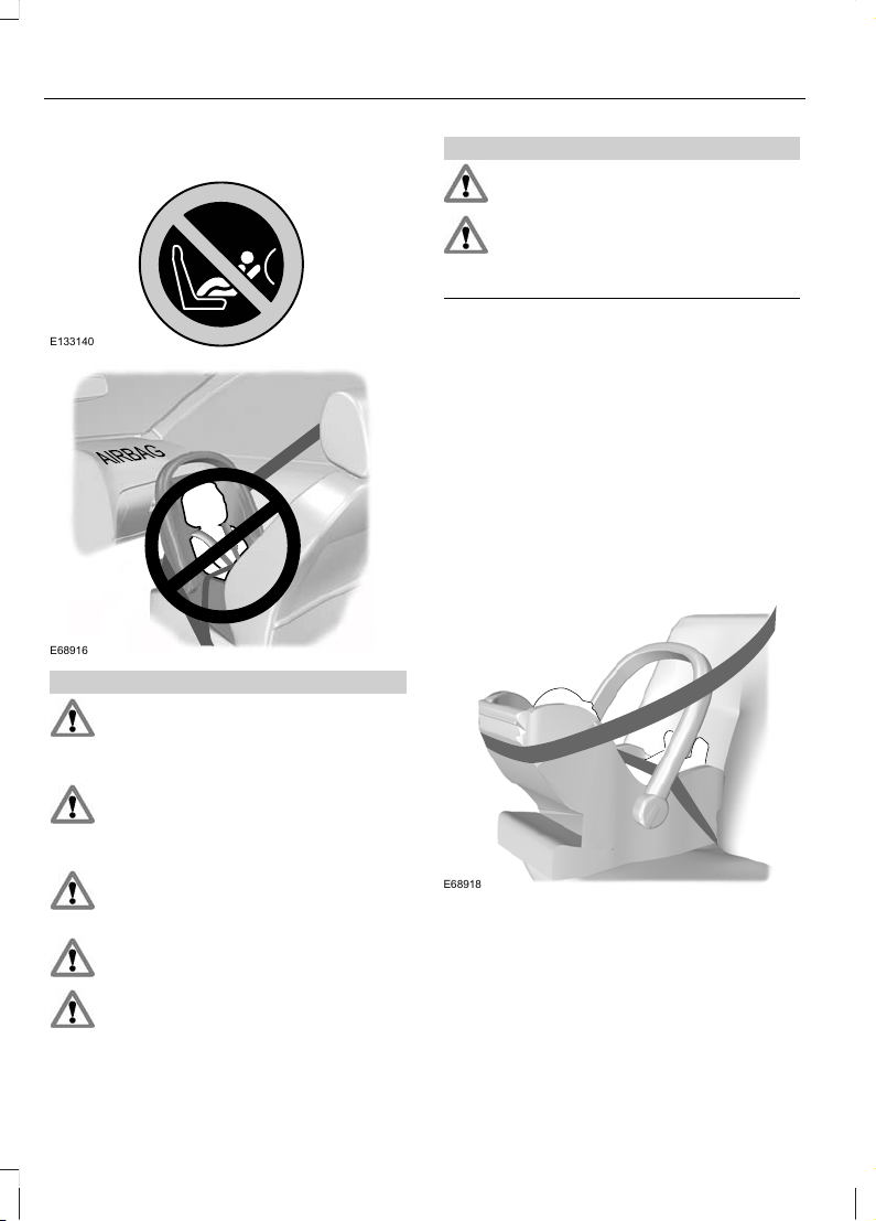
Use the correct child restraint as follows:
Baby safety seat
E68918
Secure children that weigh less than 13
kilograms (29 pounds) in a rearward facing
baby safety seat (Group 0+) in the rear
seat.
22
Child Safety
Page 25
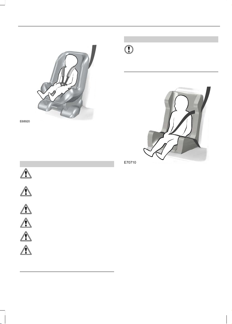
Child safety seat
E68920
Secure children that weigh between 13 and
18 kilograms (29 and 40 pounds) in a child
safety seat (Group 1) in the rear seat.
BOOSTER SEATS
WARNINGS
Do not install a booster seat or a
booster cushion with only the lap
strap of the seat belt.
Do not install a booster seat or a
booster cushion with a seat belt that
is slack or twisted.
Do not put the seat belt under your
child’s arm or behind its back.
Do not use pillows, books or towels
to boost your child’s height.
Make sure that your children sit in an
upright position.
Secure children that weigh more
than 15 kilograms (33 pounds) but
are less than 150 centimetres (59
inches) tall in a booster seat or a booster
cushion.
CAUTION
When using a child seat on a rear seat,
make sure that the child seat rests
tightly against the vehicle seat. It may
be necessary to lift or remove the head
restraint. See Head Restraints (page 122).
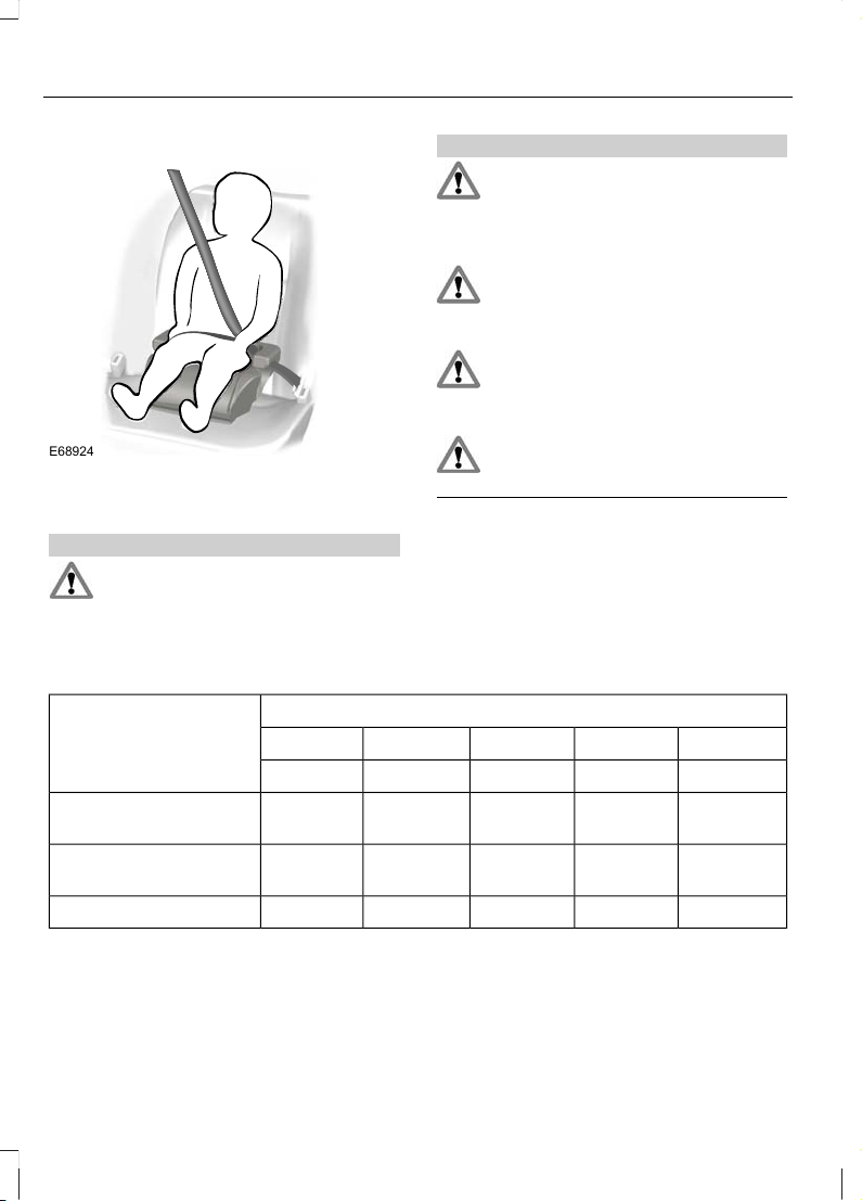
Booster seat (Group 2)
E70710
We recommend that you use a booster
seat that combines a cushion with a
backrest instead of a booster cushion only.
The raised seating position will allow you
to position the shoulder strap of the adult
seat belt over the centre of your child’s
shoulder and the lap strap tightly across
its hips.
23
Child Safety
Page 26
Booster cushion (Group 3)
E68924
CHILD SEAT POSITIONING
WARNINGS
Please consult your Dealer for the
latest details relating to Ford
recommended child seats.
WARNINGS
Original text according to ECE
R94.01: Extreme Hazard! Do not use
a rearward facing child restraint on
a seat protected by an air bag in front of
it!
When using a child restraint with a
support leg on a second row seat,
make sure the support leg rests
securely on the floor.
When using a forward facing child
seat on a second row seat, always
remove the head restraint from that
seat. See Head Restraints (page 122).
When using a child seat with a seat
belt, make sure that the seat belt is
not slack or twisted.
Note: When using a child seat on a front
seat, always adjust the front passenger seat
to its fully rearwards position. If it proves
difficult to tighten the lap section of the seat
belt without slack remaining, adjust the
seatback to the fully upright position and
raise the height of the seat. See Seats
(page 119).
Mass group categories
Seating positions 3210+0
22 - 36 kg15 - 25 kg9 - 18 kgUp to 13 kgUp to 10 kg
UF¹UF¹UF¹XX
Front passenger seat
with airbag ON
U¹U¹U¹U¹U¹
Front passenger seat
with airbag OFF
UUUUURear seats
X Not suitable for children in this mass group.
U Suitable for universal category child seats approved for use in this mass group.
U¹ Suitable for universal category child seats approved for use in this mass group. However,
we recommend that you secure children in a government approved child seat, in the rear
seat.
24
Child Safety
Page 27

UF¹ Suitable for universal category forward facing child seats approved for use in this
mass group. However, we recommend that you secure children in a government approved
child seat, in the rear seat.
ISOFIX child seats
Mass group categories
Seating positions
10+
Forward facingRear facing
9 - 18 kgUp to 13 kg
Not ISOFIX equipped
Size classFront seat
Seat type
A, B, B1, C, D
*
C, D, E
*
Size class
Rear outboard seat ISOFIX
IL, IUF
***
IL
**
Seat type
Not ISOFIX equipped
Size classRear centre seat
Seat type
IL Suitable for particular ISOFIX child restraints systems of the semi-universal category.
Please consult child restraints systems suppliers' vehicle recommendation lists.
IUF Suitable for ISOFIX forward facing child restraints systems of universal category
approved for use in this mass group and ISOFIX size class.
*
The ISOFIX size class for both universal and semi-universal child restraints systems
is defined by the capital letters A to G. These identification letters are displayed on ISOFIX
child restraints.
**
At time of publishing the recommended Group O+ ISOFIX baby safety seat is the Britax
Romer Baby Safe. Please consult your Dealer for the latest details relating to Ford
recommended child seats.
***
At time of publishing the recommended Group 1 ISOFIX child seat is the Britax Romer
Duo. Please consult your Dealer for the latest details relating to Ford recommended child
seats.
25
Child Safety
Page 28
ISOFIX ANCHOR POINTS
WARNING
Use an anti-rotation device when
using the ISOFIX system. We
recommend the use of a top tether
or support leg.
Your vehicle is fitted with ISOFIX anchor
points that accommodate universally
approved ISOFIX child restraints.
The ISOFIX system comprises two rigid
attachment arms on the child restraint that
attach to anchor points on the outboard
rear seats, where the cushion and backrest
meet. Tether anchor points are fitted
behind the outboard rear seats for child
restraints with a top tether.
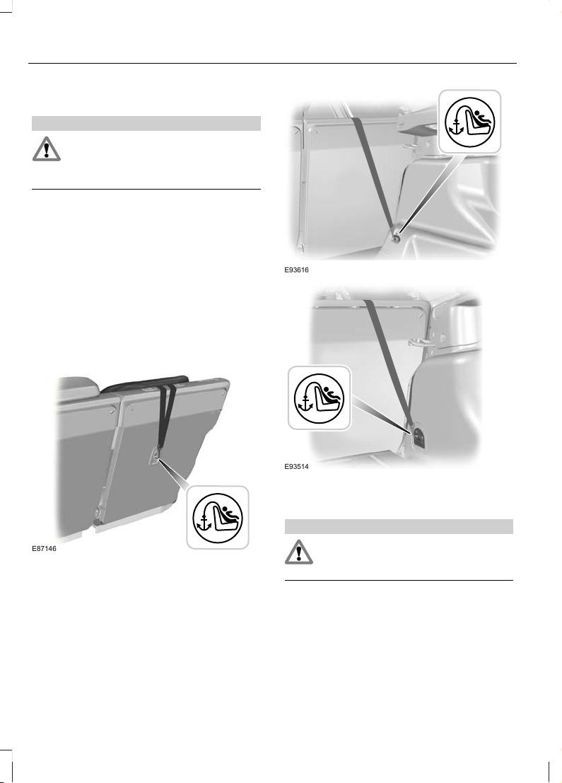
Top tether anchor points
E87146
E93616
E93514
Attaching a child seat with top
tethers
WARNING
Do not attach a tether strap to
anything other than the correct
tether anchor point.
Note: Where applicable, remove the
luggage cover to ease installation. See
Luggage Covers (page 181).
Note: On 4-door vehicles, make sure the
tether strap tightening mechanism remains
accessible when the seatback is fully
engaged.
26
Child Safety
Page 29
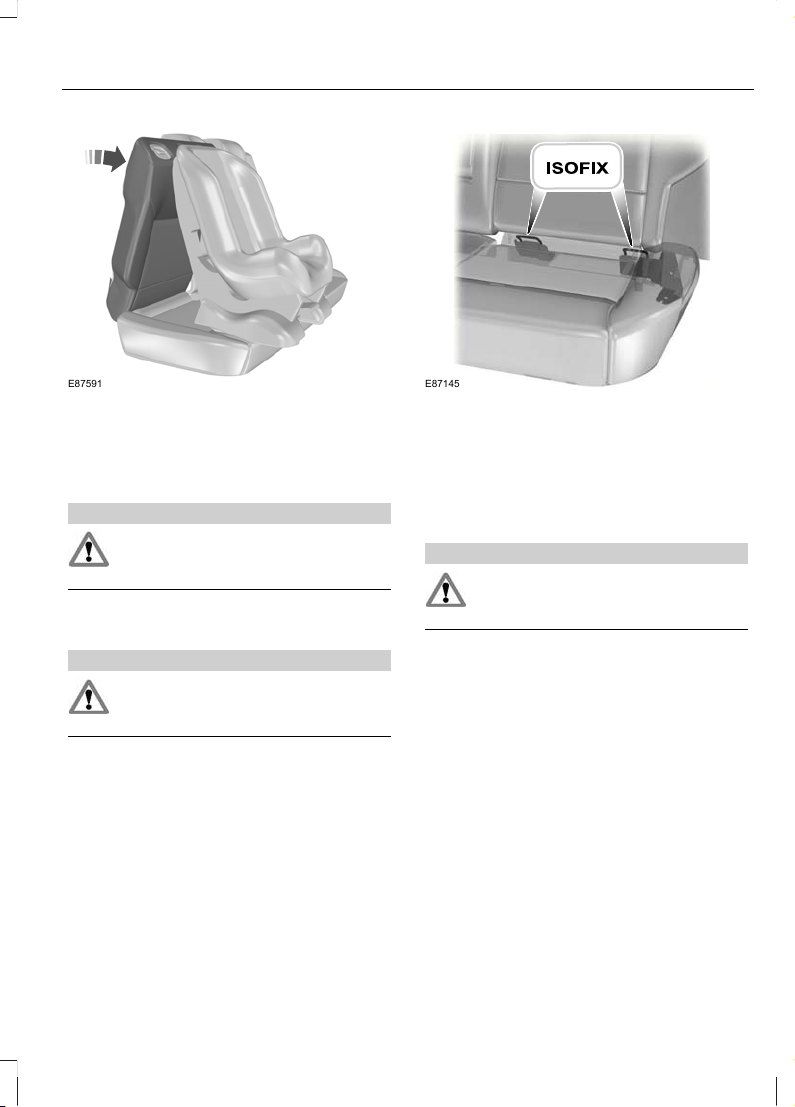
E87591
1. Place the child seat on the back seat
cushion and fold the relevant seatback
forwards. See Rear Seats (page 122).
2. Remove the head restraint. See Head
Restraints (page 122).
WARNING
Make sure the top tether strap is not
slack or twisted and is properly
located on the anchor point.
3. Route the tether strap to the anchor
point.
WARNING
Make sure that the seatback is
secure and fully engaged in the
catch.
4. Push the seatback to the upright
position.
E87145
5. Push the child seat back firmly to
engage the ISOFIX lower anchor points.
6. Tighten the tether strap in line with the
child seat manufacturer's instructions.
CHILD SAFETY LOCKS
WARNING
You cannot open the doors from
inside if you have put the child safety
locks on.
Manual child safety locks
Note: On vehicles with keyless entry, use
the spare key. See Keyless Entry (page
40).
27
Child Safety
Page 30
E78298
Left-hand side
Turn anti-clockwise to lock and clockwise
to unlock.
Right-hand side
Turn clockwise to lock and anti-clockwise
to unlock.
Electric child safety locks
Note: Pressing the switch will also disable
the rear electric window switches.
E124779
28
Child Safety
Page 31

PRINCIPLE OF OPERATION
Airbags
WARNINGS
Do not modify the front of your
vehicle in any way. This could
adversely affect deployment of the
airbags.
Original text according to ECE
R94.01: Extreme Hazard! Do not use
a rearward facing child restraint on
a seat protected by an airbag in front of it!
Wear a seat belt and keep sufficient
distance between yourself and the
steering wheel. Only when you use
the seat belt properly, can it hold you in a
position that allows the airbag to achieve
its optimum effect. See Sitting in the
Correct Position (page 119).
Have repairs to the steering wheel,
steering column, seats, airbags and
seat belts carried out by a properly
trained technician.
Keep the areas in front of the airbags
free from obstruction. Do not affix
anything to or over the airbag covers.
Do not poke sharp objects into areas
where airbags are fitted. This could
damage and adversely affect
deployment of the airbags.
Use seat covers designed for seats
with side airbags. Have these fitted
by a properly trained technician.
Note: You will hear a loud bang and see a
cloud of harmless powdery residue if an
airbag deploys. This is normal.
Note: Only wipe airbag covers with a damp
cloth.
Driver and front passenger airbags
E74302
The driver and front passenger airbags will
deploy during significant frontal collisions
or collisions that are up to 30 degrees from
the left or the right. The airbags will inflate
within a few thousandths of a second and
deflate on contact with the occupants,
thus cushioning forward body movement.
During minor frontal collisions, overturns,
rear collisions and side collisions, the driver
and front passenger airbags will not
deploy.
Driver knee airbag
CAUTION
Do not attempt to open the driver
knee airbag cover.
The driver knee airbag will deploy during
frontal collisions or collisions that are up
to 30 degrees from the left or the right. The
airbag will inflate within a few thousandths
of a second and deflate on contact with
the occupants, thus providing a cushion
between the driver’s knees and the steering
column. During overturns, rear collisions
and side collisions, the knee airbag will not
deploy.
For item location: See At a Glance (page
11).
29
Occupant protection
Page 32

Note: The knee airbag has a lower
deployment threshold than the front
airbags. During a minor collision, it is
possible that only the knee airbag deploys.
Side airbags
E72658
Side airbags are fitted inside the seatback
of the front seats. A label indicates that
side airbags are fitted to your vehicle.
The side airbags will deploy during
significant lateral collisions. The airbags
will inflate within a few thousandths of a
second and deflate on contact with the
occupants, thus providing protection for
the chest and shoulder areas. During minor
lateral collisions, overturns, front collisions
and rear collisions, the side airbags will not
deploy.
Curtain airbags
E75004
Curtain airbags are fitted inside the trim
panels over the front and rear side
windows. Moulded badges in the B-pillar
trim panels indicate that curtain airbags
are fitted to your vehicle.
The curtain airbags will deploy during
significant lateral collisions. The airbag will
inflate within a few thousandths of a
second and deflate on contact with the
occupants, thus providing protection for
the head. During minor lateral collisions,
front collisions, rear collisions, or overturns
the curtain airbags will not deploy.
Seat belts
WARNINGS
Wear a seat belt and keep sufficient
distance between yourself and the
steering wheel. Only when you use
the seat belt properly, can it hold you in a
position to achieve its optimum effect. See
Sitting in the Correct Position (page
119).
Never use a seat belt for more than
one person.
Use the correct buckle for each seat
belt.
Do not use a seat belt that is slack
or twisted.
Do not wear thick clothing. The seat
belt must fit tightly around your body
to achieve its optimum effect.
Position the shoulder strap of the
seat belt over the centre of your
shoulder and position the lap strap
tightly across your hips.
30
Occupant protection
Page 33

The driver and front passenger seat belt
retractors are fitted with a seat belt
pretensioner. Seat belt pretensioners have
a lower deployment threshold than the
airbags. During minor collisions, it is
possible that only the seat belt
pretensioners will deploy.
Status after a collision
WARNING
Seat belts subjected to strain, as a
result of an accident, should be
renewed and the anchorages
checked by a properly trained technician.
FASTENING THE SEAT BELTS
WARNING
Insert the tongue into the buckle until
you hear a distinct click. You have
not fastened the seat belt properly
if you do not hear a click.
E74124
E85817
Pull the belt out steadily. It may lock if you
pull it sharply or if the vehicle is on a slope.
Press the red button on the buckle to
release the belt. Let it retract completely
and smoothly.
SEAT BELT HEIGHT ADJUSTMENT
E87511
Note: Lifting the slider slightly while
pressing the locking button makes it easier
to release the locking mechanism.
To raise or lower, press the locking button
on the adjuster and move as necessary.
31
Occupant protection
Page 34

SEAT BELT REMINDER
WARNING
The occupant protection system will
only provide optimum protection
when you use the seat belt properly.
The seat belt reminder warning
lamp illuminates and an audible
warning will sound if the driver's
or front seat passenger's seat belt has not
been fastened and the vehicle exceeds a
relatively low speed. It will also illuminate
if the driver's or front seat passenger's seat
belt is unfastened when the vehicle is
moving. The audible warning and warning
lamp will go off after seven minutes.
Deactivating the seat belt
reminder
See your dealer.
USING SEAT BELTS DURING PREGNANCY
E68587
WARNING
Position the seat belt correctly for
your safety and that of your unborn
child. Do not use only the lap strap
or the shoulder strap.
Position the lap strap comfortably across
your hips and low beneath your pregnant
abdomen. Position the shoulder strap
between your breasts, above and to the
side of your pregnant abdomen.
DISABLING THE PASSENGER AIRBAG
WARNING
Make sure that the passenger airbag
is disabled when using a rearward
facing child restraint on the front
passenger seat.
E71313
Fitting the passenger airbag
deactivation switch
WARNING
If you need to fit a child restraint on
a seat protected by an operational
airbag in front of it, have a passenger
airbag deactivation switch fitted. Ask your
dealer for further information.
Note: The key switch is located in the glove
compartment with an airbag deactivation
lamp in the instrument panel.
32
Occupant protection
Page 35

If the airbag warning lamp illuminates or
flashes when you are driving, this indicates
a malfunction. See Warning Lamps and
Indicators (page 80). Remove the child
restraint and have the system checked
immediately.
Disabling the passenger airbag
A B
E71312
DisabledA
EnabledB
Turn the switch to position A.
When you switch the ignition on, check that
the passenger airbag deactivation warning
lamp illuminates.
Enabling the passenger airbag
WARNING
Make sure that the passenger airbag
is enabled when you are not using a
child restraint on the front passenger
seat.
Turn the switch to position B.
33
Occupant protection
Page 36
GENERAL INFORMATION ON RADIO FREQUENCIES
CAUTIONS
The radio frequency used by your
remote control can also be used by
other short distance radio
transmissions (e.g. amateur radios,
medical equipment, wireless headphones,
remote controls and alarm systems). If the
frequencies are jammed, you will not be
able to use your remote control. You can
lock and unlock the doors with the key.
Check your vehicle is locked before
leaving it unattended. This will
safeguard against any potential
malicious frequency blocking.
Note: You could unlock the doors if you
press the buttons on the remote control
unintentionally.
The operating range between your remote
control and your vehicle varies depending
on the environment.
PROGRAMMING THE REMOTE CONTROL
You can programme a maximum of eight
remote controls to use with your vehicle
(including any supplied with your vehicle).
Programming a new remote
control
1. Insert the key in the ignition.
2. Cycle the key from position 0 to II and
then back to 0 four times within six
seconds.
3. Leave the key in position 0 and press
any button on the remote control
within 10 seconds. You will receive
confirmation via a chime or LED that
programming has been successful.
Note: Further remote controls may be
programmed at this stage.
4. Press any button on each additional
remote control within 10 seconds of
each other.
Reprogramming the unlocking
function
Note: When you press the unlock button
either all the doors are unlocked or only the
driver’s door is unlocked. Pressing the unlock
button again unlocks all the doors.
Press and hold the unlock and lock buttons
on the remote key simultaneously for at
least four seconds with the ignition off. The
direction indicators will flash twice to
confirm the change.
To return to the original unlocking function,
repeat the process.
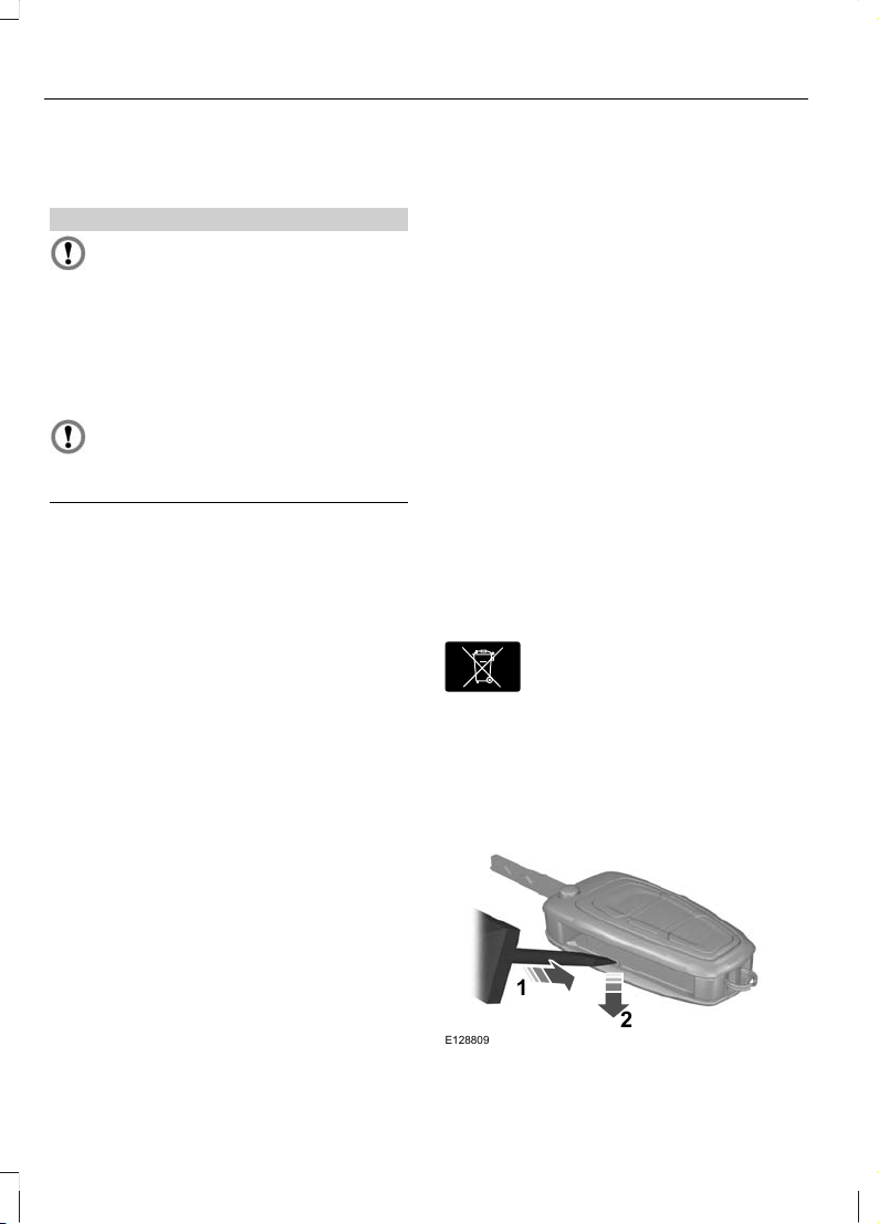
CHANGING THE REMOTE CONTROL BATTERY
E107998
Make sure that you dispose of
old batteries in an
environmentally friendly way.
Seek advice from your local authority
regarding recycling.
Remote control with a folding key
blade
E128809
2
1
34
Keys and Remote Controls
Page 37

1. Insert a screwdriver in the position
shown and gently push the clip.
2. Press the clip down to release the
battery cover.
E128810
3. Carefully remove the cover.
E128811
4. Turn the remote control over to remove
the battery.
5. Install a new battery (3V CR 2032) with
the + facing upwards.
6. Replace the battery cover.
Remote control without a folding
key blade
1
2
1
E87964
1. Press and hold the pushbuttons on the
edges to release the cover. Carefully
remove the cover.
2. Remove the key blade.
E105362
3
3. Twist a flat bladed screwdriver in the
position shown to separate the two
halves of the remote control.
35
Keys and Remote Controls
Page 38

E119190
4
4. Carefully insert the screwdriver in the
position shown to open the remote
control.
E125860
5
CAUTION
Do not touch the battery contacts or
the printed circuit board with the
screwdriver.
5. Carefully prise out the battery with the
screwdriver.
6. Install a new battery (3V CR 2032) with
the + facing downwards.
7. Assemble the two halves of the remote
control.
8. Install the key blade.
36
Keys and Remote Controls
Page 39

LOCKING AND UNLOCKING
CAUTION
Check your vehicle is locked before
leaving it unattended.
Central locking
You can only centrally lock the doors if they
are all closed.
Note: The driver’s door can be unlocked
with the key. This needs to be used if the
remote control or keyless entry is not
functioning.
Note: Central locking also locks and
unlocks the fuel filler flap.
Double locking
WARNING
Do not activate double locking when
persons or animals are inside the
vehicle. You will not be able to
unlock the doors from the inside if you have
double locked them.
E71961
Double locking is a theft protection feature
that prevents someone from opening the
doors from the inside. You can only double
lock the doors if they are all closed.
Locking and unlocking
confirmation
When you unlock the doors, the direction
indicators will flash once.
When you lock the doors, the direction
indicators will flash twice.
Locking and unlocking the doors
with the key
B
E71962
A
B
A
UnlockA
LockB
Double locking the doors with the
key
Turn the key to the lock position twice
within three seconds to double lock the
doors.
37
Locks
Page 40

Locking and unlocking the doors
and the luggage compartment lid
with the remote control
E87379
A B C
UnlockA
LockB
Luggage compartment lid unlock
(press twice)
C
Locking the doors and the luggage
compartment lid with the remote
control
Press button B once.
Double locking the doors and the
luggage compartment lid with the
remote control
Press button B twice within three seconds.
Locking and unlocking the doors
from inside
Driver's door
A
B
E71958
Lock all doorsA
Unlock all doorsB
Front and rear passenger doors
E98653
To lock the front and rear passenger doors
individually, press the button and close the
door when leaving the vehicle.
38
Locks
Page 41

Luggage compartment lid
Opening the luggage compartment lid
with the remote control
Press button C on the remote control twice
within three seconds.
Closing the luggage compartment lid
4-door
E89131
5-door
E89132
Estate
E89133
A recessed grip is incorporated inside the
luggage compartment lid to facilitate
closing.
Automatic relocking
The doors will relock automatically if you
do not open a door within 45 seconds of
unlocking the doors with the remote
control. The door locks and the alarm will
return to their previous state.
Reprogramming the unlocking
function
The unlocking function may be
reprogrammed so that only the driver’s
door is unlocked. See Programming the
remote control (page 34).
GLOBAL OPENING AND CLOSING
You can also operate the electric windows
with the ignition off via the global opening
and global closing function.
Note: Global closing will only operate if you
have set the memory correctly for each
window. See Power Windows (page 71).
39
Locks
Page 42

Global opening
E71955
To open all the windows, press and hold
the unlock button for at least three
seconds. Press either the lock or the
unlock button again to stop the opening
function.
Global closing
Vehicles without keyless entry
WARNING
Take care when using global closing.
In an emergency, press a button
immediately to stop.
E71956
To close all the windows, press and hold
the lock button for at least three seconds.
Press any button again to stop the closing
function. The anti-trap function is also
active during global closing.
Vehicles with keyless entry
E87384
WARNING
Take care when using global closing.
In an emergency, press the button
on the driver’s door handle to stop.
Note: Global closing can be activated using
the button on the driver’s door handle.
Global opening and closing can also be
activated using the buttons on the passive
key.
To close all the windows, press and hold
the button on the driver’s door handle for
at least two seconds. The anti-trap
function is also active during global closing.
KEYLESS ENTRY
General information
WARNING
The keyless entry system may not
function if the key is close to metal
objects or electronic devices such as
mobile phones.
40
Locks
Page 43

Note: If the door handles are pulled
repeatedly during a short period of time
without the presence of a valid passive key,
the system will become inoperable for 30
seconds.
The passive entry system will not function
if:
• The passive key frequencies are
jammed.
• The passive key battery is flat.
Note: If the passive entry system does not
function, you will need to use the key blade
to lock and unlock your vehicle.
The keyless system allows the driver to
operate the vehicle without the use of a
key or remote control.
E78276
Passive locking and unlocking requires a
valid passive key to be located within one
of the three external detection ranges.
These are located approximately one and
a half metres from the driver and front
passenger door handles and the luggage
compartment lid.
Passive key
The vehicle can be locked and unlocked
with the passive key. The passive key can
also be used as a remote control. See
Locking and Unlocking (page 37).
Locking the vehicle
WARNING
The vehicle does not lock itself
automatically. If no locking button is
pressed, the vehicle will remain
unlocked.
Note: The ignition will automatically switch
off when you lock your vehicle from the
outside. This is to prevent the vehicle battery
from discharging.
Note: If locking from the luggage
compartment lid, the passive key must be
within the luggage compartment lid
detection range.
E87384
E87435
Locking buttons are located on each of the
front doors and the luggage compartment
lid.
41
Locks
Page 44
To activate central locking and arm the
alarm:
• Press a locking button once.
To activate double locking, to arm the
alarm and the interior sensors:
• Press a locking button twice within
three seconds.
Note: Once activated, the vehicle will
remain locked for approximately three
seconds. This is to allow you to pull a door
handle and check if the vehicle is locked.
When the delay period is over, the doors can
be opened again, provided the passive key
is within the respective detection range.
Luggage compartment lid
Note: The luggage compartment lid cannot
be closed and will pop back up if the passive
key is located inside the luggage
compartment.
Note: If a second valid passive key is
located within the luggage compartment
lid detection range, the luggage
compartment lid can be closed.
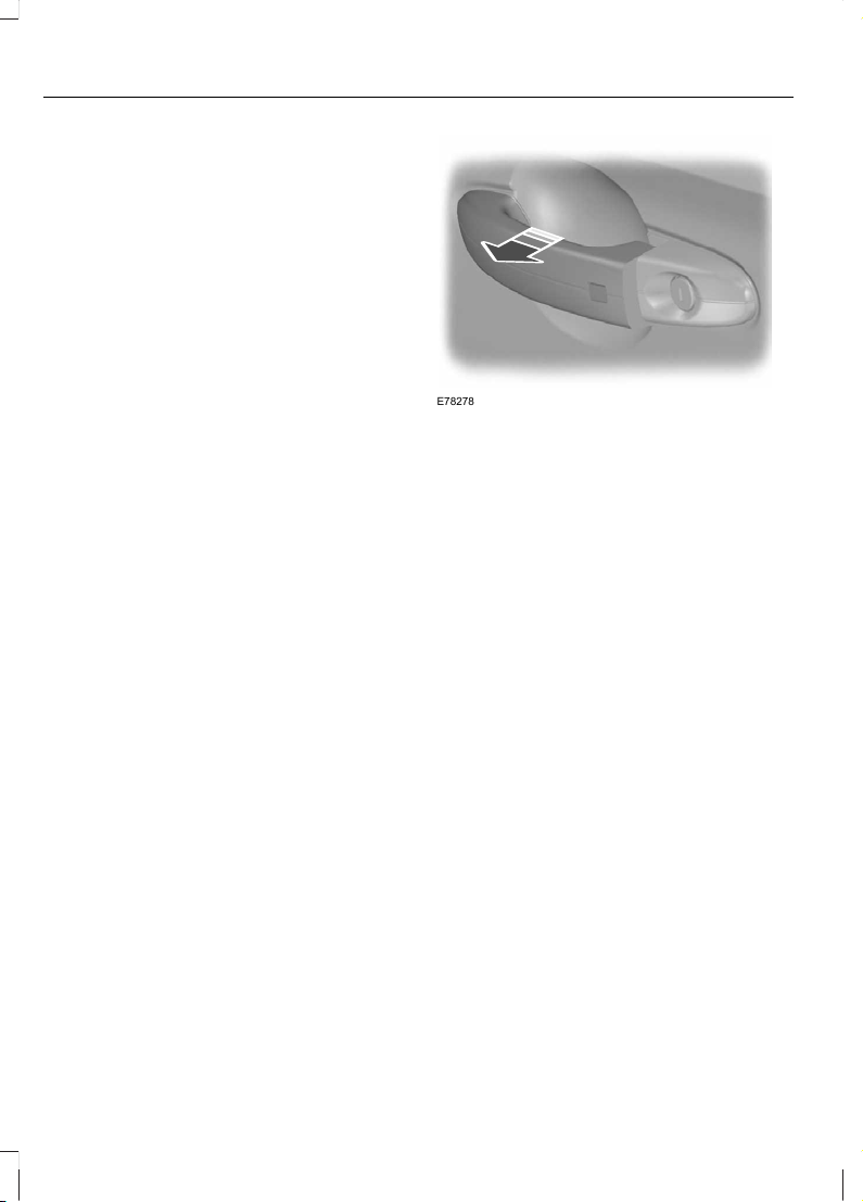
Unlocking the vehicle
Note: If the vehicle remains locked for
longer than five days, the system will enter
an energy-saving mode. This is to reduce
the discharge of the vehicle battery. When
the vehicle is unlocked while in this mode,
the reaction time of the system may be a
little longer than normal. Unlocking the
vehicle once will deactivate the
energy-saving mode.
E78278
Pull one of the door handles or the luggage
compartment lid handle.
Note: A valid passive key must be located
within the detection range of that door.
One long flash of the direction indicators
confirms that all the doors, the luggage
compartment lid and the fuel filler flap
have been unlocked and that the alarm
has been disarmed.
Unlocking only the driver's door
If the unlocking function is reprogrammed
so that only the driver’s door is unlocked (
See Keys and Remote Controls (page
34). ), note the following:
If the driver’s door is the first door which is
opened, the other doors and the luggage
compartment lid will remain locked. All the
other doors can be unlocked from inside
the vehicle by pressing the unlock button
next to the driver’s door handle. Doors can
be unlocked individually by pulling the
interior door handles on those doors.
If the front passenger door or one of the
rear doors is the first door which is opened,
all the doors and the luggage
compartment lid will be unlocked.
42
Locks
Page 45

Disabled keys
Any keys left inside the vehicle interior
when it is locked will be disabled.
A disabled key cannot be used to turn the
ignition on or start the engine.
In order to use these passive keys again,
they have to be enabled.
To enable all your passive keys, unlock the
vehicle using a passive key or the remote
control unlocking function.
All passive keys will then be enabled if the
ignition is turned on or the vehicle is started
using a valid key.
Locking and unlocking the doors
with the key blade
1
2
1
E87964
1. Carefully remove the cover.
2. Remove the key blade and insert it into
the lock.
43
Locks
Page 46

PRINCIPLE OF OPERATION
The engine immobiliser is a theft protection
system that prevents someone from
starting the engine with an incorrectly
coded key.
CODED KEYS
Note: Do not shield your keys with metal
objects. This may prevent the receiver from
recognising your key as a valid one.
Note: Have all of your remaining keys
erased and recoded if you lose a key. Ask
your dealer for further information. Have
replacement keys recoded together with
your existing keys.
If you lose a key, you can obtain a
replacement from your Ford Dealer. If
possible, provide them with the key
number from the tag provided with the
original keys. You can also obtain
additional keys from your Ford Dealer.
ARMING THE ENGINE IMMOBILISER
The engine immobiliser is armed
automatically a short time after you have
switched the ignition off.
DISARMING THE ENGINE IMMOBILISER
The engine immobiliser is disarmed
automatically when you switch the ignition
on with a correctly coded key.
If the message Immobiliser active
appears in the information display, your
key has not been recognised. Remove the
key and try again.
If you are unable to start the engine with a
correctly coded key, this indicates a
malfunction. The message Immobiliser
active will appear in the information
display when you switch on the ignition.
Have the immobiliser checked
immediately.
44
Engine immobiliser
Page 47
PRINCIPLE OF OPERATION
Alarm system
Your vehicle may be equipped with one of
the following alarm systems:
• Perimeter alarm.
• Perimeter alarm with interior sensors.
• Category one alarm with interior
sensors and battery back-up sounder.
• Category one alarm with interior
sensors, battery back-up sounder and
tilt sensors.
Perimeter alarm
The perimeter alarm is a deterrent against
unauthorised access to your vehicle
through the doors and the bonnet. It also
protects the audio unit.
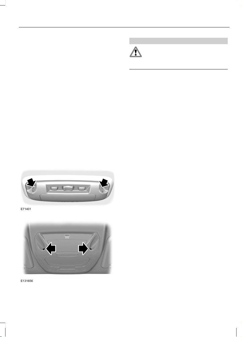
Interior sensors
Vehicles without overhead console
E71401
Vehicles with overhead console
E131656
WARNING
The sensors must not be covered up.
Do not activate the alarm with full
guard if any persons, animals or other
moving objects are inside the vehicle.
The sensors act as a deterrent against
unauthorised intrusion by sensing any
movement within the vehicle.
Battery back-up sounder
The battery back-up sounder is an extra
alarm system which will sound a siren
when the alarm is triggered. It is armed
directly when you lock the vehicle. The
sounder has its own battery and will sound
an alarm siren even if someone
disconnects the vehicle battery or the
battery back-up sounder itself.
Tilt sensors
The tilt sensors detect if someone
attempts to steal a wheel or tow the
vehicle away by sensing changes in the
inclination of the vehicle.
Note: When travelling on a ferry with the
alarm armed, deactivate the tilt sensors by
selecting reduced guard. This will prevent
the alarm from being triggered by the
movement.
Triggering the alarm
Once armed, the alarm is triggered in any
of the following ways:
• If someone opens a door, the tailgate
or the bonnet without a valid key or
remote control.
• If someone removes the audio or
navigation system.
• If the ignition is turned to position I, II
or III without a valid key.
• If the interior sensors detect movement
within the vehicle.
45
Alarm
Page 48

• On vehicles with a battery back-up
sounder, if someone disconnects the
vehicle battery or the battery back-up
sounder itself.
• If the tilt sensors detect a change in the
inclination of the vehicle.
If the alarm is triggered, the alarm horn will
sound for 30 seconds and the hazard
warning flasher will flash for five minutes.
Any further attempts to perform one of the
above will trigger the alarm again.
Full and reduced guard
Full guard
Full guard is the standard setting.
In full guard, the interior and tilt sensors
are activated when you arm the alarm.
Note: This may result in false alarms if
animals or moving objects are inside the
vehicle or, on vehicles with tilt sensors, when
travelling on a ferry.
Note: False alarms can also be triggered
by the auxiliary heater See Auxiliary Heater
(page 112). If you are using the auxiliary
heater, direct the air flow towards the
footwell.
Reduced guard
In reduced guard, the interior and tilt
sensors are deactivated when you arm the
alarm.
Note: You can set the alarm to reduced
guard for the current ignition cycle only. The
next time you switch on the ignition, the
alarm will be reset to full guard.
Ask on Exit
You can set the information display to ask
you each time which level of guard you
wish to set.
If you select Ask on Exit, the message
Reduced guard? appears in the
instrument cluster display each time you
switch the ignition off.
If you wish to arm the alarm with reduced
guard, press the OK button when this
message appears.
If you wish to arm the alarm with full guard,
leave the vehicle without pressing the OK
button.
Selecting full or reduced guard
Note: Selecting Reduced does not set the
alarm permanently to reduced guard. It sets
it to reduced guard only for the current
ignition cycle. If you regularly set the alarm
to reduced guard, select Ask on Exit.
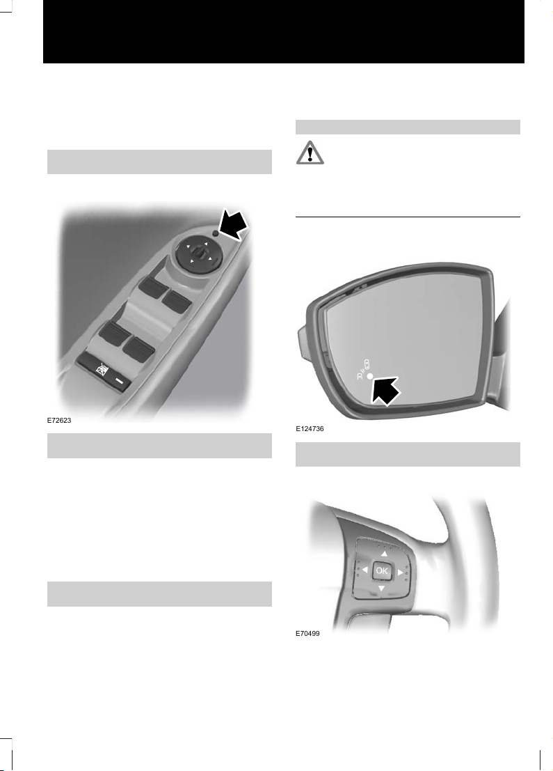
E70499
E74509
Full Guard
Alarm
Reduced
Ask on Exit
46
Alarm
Page 49

1. Press the right arrow button on the
steering wheel to enter the main menu.
2. Highlight Setup with the up and down
arrow buttons and press the right arrow
button.
3. Highlight Alarm and press the right
arrow button.
4. Highlight Reduced or Full guard. If
you prefer to be asked each time you
switch off the ignition, select Ask on
Exit.
5. Press the OK button to confirm the
selection.
6. Press the left arrow button to exit the
menu. To return to the trip computer
display directly, hold the left arrow
button pressed.
Information messages
See Information Messages (page 97).
ARMING THE ALARM
To arm the alarm, lock the vehicle. See
Locks (page 37).
DISARMING THE ALARM
Vehicles without keyless entry
Perimeter alarm
Disarm and silence the alarm by unlocking
the doors with the key and switching the
ignition on with a correctly coded key, or
unlocking the doors or the luggage
compartment lid with the remote control.
Category one alarm
Disarm and silence the alarm by unlocking
the doors with the key and switching the
ignition on with a correctly coded key
within 12 seconds, or unlocking the doors
or the luggage compartment lid with the
remote control.
Vehicles with keyless entry
Note: A valid passive key must be located
within the detection range of that door for
keyless entry. See Keyless Entry (page 40).
Perimeter alarm
Disarm and silence the alarm by unlocking
the doors and switching the ignition on, or
unlocking the doors or the luggage
compartment lid with the remote control.
Category one alarm
Disarm and silence the alarm by unlocking
the doors and switching the ignition on
within 12 seconds, or unlocking the doors
or the luggage compartment lid with the
remote control.
47
Alarm
Page 50

ADJUSTING THE STEERING WHEEL
WARNING
Never adjust the steering wheel
when the vehicle is moving.
Note: Make sure that you are sitting in the
correct position. See Sitting in the Correct
Position (page 119).
1
2
2
E95178
3
E95179
WARNING
Make sure that you fully engage the
locking lever when returning it to its
original position.
AUDIO CONTROL
E72288
A
C
B
D
E
Volume upA
Seek upB
Volume downC
Seek downD
ModeE
Mode
Press and hold the mode button to select
the audio source.
Press the mode button to:
• tune the radio to the next preset
station
• play the next CD
• play the other side of a cassette tape
• accept an incoming telephone call.
• end a telephone call.
48
Steering Wheel
Page 51

Seek
Press a seek button to:
• tune the radio to the next station up or
down the frequency band
• play the next or the previous CD track
• fast forward or rewind the cassette
tape.
Press and hold a seek button to:
• tune the radio up or down the
frequency band
• seek through a CD track.
49
Steering Wheel
Page 52

WINDSCREEN WIPERS
B
C
D
A
E70696
Single wipeA
Intermittent wipeB
Normal wipeC
High speed wipeD
Intermittent wipe
E70315
B
A
C
Short wipe intervalA
Intermittent wipeB
Long wipe intervalC
AUTOWIPERS
CAUTIONS
Do not switch autowipers on in dry
weather conditions. The rain sensor
is very sensitive and the wipers may
operate if dirt, mist or flies hit the
windscreen.
Replace the wiper blades as soon as
they begin to leave bands of water
and smears. If you do not replace
them, the rain sensor will continue to
detect water on the windscreen and the
wipers will operate, even though the
majority of the windscreen is dry.
Fully defrost the windscreen in icy
conditions before you switch
autowipers on.
Switch autowipers off before you
enter a car wash.
E70315
B
A
C
High sensitivityA
OnB
Low sensitivityC
If you switch autowipers on, the wipers will
not cycle until water is detected on the
windscreen. The rain sensor will then
continuously measure the amount of water
on the windscreen and adjust the speed
of the wipers automatically.
50
Wipers and Washers
Page 53

Adjust the sensitivity of the rain sensor
using the rotary control. With low
sensitivity, the wipers will operate when
the sensor detects a lot of water on the
windscreen. With high sensitivity, the
wipers will operate if the sensor detects a
small amount of water on the windscreen.
WINDSCREEN WASHERS
WARNING
Do not operate the windscreen
washers for more than 10 seconds
or when the reservoir is empty.
Note: The washer jets are heated when the
ignition is on.
E70776
REAR WINDOW WIPER AND WASHERS
Intermittent wipe
E70777
Reverse gear wipe
The rear window wiper will operate
automatically when you select reverse gear
if the wiper lever is in position B, C or D.
Washer
WARNING
Do not operate the rear window
washer for more than 10 seconds or
when the reservoir is empty.
E70777
Pull the lever fully towards the steering
wheel and hold it to operate the washer.
51
Wipers and Washers
Page 54
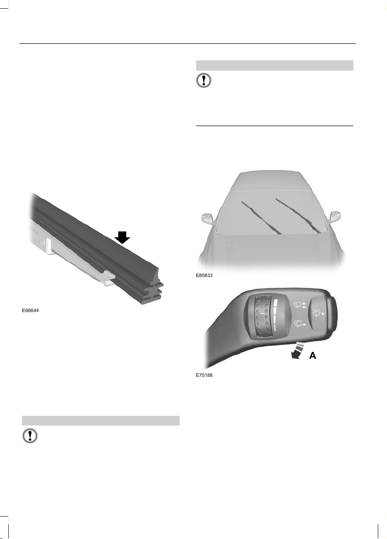
HEADLAMP WASHERS
The headlamp washers will operate with
the windscreen washers when the
headlamps are on.
Note: To stop the washer fluid reservoir
emptying quickly, the headlamp washers
will not operate every time that you use the
windscreen washers.
CHECKING THE WIPER BLADES
E66644
Run the tip of your fingers over the edge of
the blade to check for roughness.
Clean the wiper blade lips with water
applied with a soft sponge.
CHANGING THE WIPER BLADES
Windscreen wiper blades
CAUTIONS
Set the windscreen wipers in the
service position to change the wiper
blades.
CAUTIONS
You can use the service position in
winter to provide easier access to the
wiper blades for freeing them from
snow and ice. Make sure that the outside
of the windscreen is free from snow and
ice before using the wipers.
Service position
E85833
A
E75188
Switch off the ignition and move the wiper
lever to position A within three seconds.
Release the lever when the windscreen
wipers have moved to the service position.
Changing the windscreen wiper blades
Set the windscreen wipers in the service
position and lift the wiper arms.
52
Wipers and Washers
Page 55

E72899
1
2
1. Press the locking button.
2. Remove the wiper blade.
Note: Make sure that the wiper blade locks
into place.
3. Install in the reverse order.
Rear window wiper blades
Changing the rear window wiper blades
- Estate
1. Lift the wiper arm.
2
3
4
E86456
2. Position the wiper blade at right angles
to the wiper arm.
3. Disengage the wiper blade from the
wiper arm.
4. Remove the wiper blade.
Note: Make sure that the wiper blade locks
into place.
5. Install in the reverse order.
Changing the rear window wiper blades
- 5-door
1. Lift the wiper arm.
E86457
2
3
2. Press the locking button.
3. Remove the wiper blade.
Note: Make sure that the wiper blade locks
into place.
4. Install in the reverse order.
53
Wipers and Washers
Page 56

LIGHTING CONTROL
Lighting control positions
E70718
A B C
OffA
Side and tail lampsB
HeadlampsC
Parking lamps
CAUTION
Prolonged use of the parking lamps
will discharge the battery.
Switch off the ignition.
Both sides
Set the lighting control to position B.
One side
E75505
A
B
Right-hand sideA
Left-hand sideB
Main and dipped beam
E70725
Pull the lever fully towards the steering
wheel to switch between main and dipped
beam.
Headlamp flasher
Pull the lever slightly towards the steering
wheel.
54
Lighting
Page 57

Home safe lighting
Switch the ignition off and pull the
direction indicator lever towards the
steering wheel to switch the headlamps
on. You will hear a short tone. The
headlamps will go off automatically after
three minutes with any door open, or 30
seconds after the last door has been
closed.
With all doors closed, but within the 30
second delay, opening any door will result
in the three minute timer starting again.
The home safe lights can be cancelled by
either pulling the direction indicator lever
towards the steering wheel again or by
turning the ignition switch on.
DAYTIME RUNNING LAMPS
The lamps will illuminate when the ignition
is on.
AUTOLAMPS
E70719
Note: If you have switched autolamps on,
you can only switch the main beam on when
autolamps has switched the headlamps on.
The headlamps will come on and go off
automatically depending on the ambient
light.
AUTOMATIC MAIN BEAM CONTROL
WARNINGS
The system does not relieve you of
your responsibility to drive with due
care and attention. A manual
override may be necessary if the system
fails to switch the main beam on or off.
A manual override may be required
when approaching other road users
such as cyclists.
Do not use the system in fog.
CAUTIONS
In cold and severe weather conditions
the system may not function. A
manual override may be necessary in
these cases.
Reflective road signs may be detected
as oncoming traffic and the
headlamps may be switched to
dipped beam.
If the lights of oncoming vehicles are
hidden by obstacles (for example
guard rails) the system may not
deactivate the main beam.
Always fit Ford Original Parts when
replacing headlamp bulbs. Other
bulbs may reduce system
performance.
Check and replace wiper blades
regularly to ensure the camera sensor
has a clear view through the
windscreen. Replacement wiper blades
must be the correct length.
55
Lighting
Page 58

Note: Keep the windscreen free from
obstructions such as bird droppings, insects
and snow or ice.
The system will automatically switch on
main beam if it is dark enough and no other
traffic is present. If it detects an
approaching vehicle’s headlamps or tail
lamps, or street lighting ahead the system
will switch off main beam before it can
distract other road users. Dipped beams
will remain on.
A camera sensor is centrally mounted
behind the windscreen of the vehicle, and
monitors conditions continuously to decide
when to switch the main beam off and on.
Once the system is active the main beam
will switch on if:
• It is dark enough to require the use of
main beams and
• there is no traffic or street lighting
ahead and
• vehicle speed is greater than 40 km/h
(25 mph).
The main beam will switch off if:
• The ambient light is high enough that
main beam is not required.
• An approaching vehicle's headlamps
or tail lamps are detected.
• Street lighting is detected.
• Vehicle speed falls below 25 km/h (16
mph).
• The camera sensor is too hot or
becomes blocked.
Activating the system
Switch on the system using the information
display and autolamps. See Information
Displays (page 84). See Autolamps
(page 55).
E70719
Turn the switch to the autolamps position.
Note: The system may take a short time to
initialise after first switching the ignition on,
especially in very dark conditions. The main
beam will not automatically switch on
during this period.
Setting the system sensitivity
The system has three sensitivity levels
which can be accessed via the information
display. See Information Displays (page
84).
The sensitivity determines the speed at
which the main beam will be restored after
detected traffic leaves the field of view.
Manually overriding the system
E70725
56
Lighting
Page 59

Use the main beam lever to switch
between main beam and dipped beam.
Note: This is a temporary override and the
system will return to automatic operation
after a short period.
To permanently deactivate the system use
the information display menu or turn the
lighting control switch from autolamps to
headlamps.
FRONT FOG LAMPS
E70721
WARNING
Only use the front fog lamps when
visibility is considerably restricted by
fog, snow or rain.
REAR FOG LAMPS
E70720
WARNINGS
Only use the rear fog lamps when
visibility is restricted to less than 50
metres (164 feet).
Do not use the rear fog lamps when
it is raining or snowing and visibility
is more than 50 metres (164 feet).
ADJUSTING THE HEADLAMPS
- VEHICLES WITH: ADAPTIVE
FRONT LIGHTING/XENON
HEADLAMPS
To adjust the headlamps for driving on the
left or right hand side of the road, see your
dealer.
HEADLAMP LEVELLING
Note: Vehicles with Xenon headlamps are
equipped with automatic headlamp
levelling.
E70722
A
B
Raised headlamp beamsA
Lowered headlamp beamsB
You can adjust the level of the headlamp
beams according to the vehicle load.
57
Lighting
Page 60

Recommended headlamp levelling switch positions
Switch positionLoad in luggage
compartment
Load
Second row seatsFront seats
0--1-2
0 (0.52)
--1-2
1 (0.52)
-31-2
3 (0.52)Max
1
31-2
4 (1.52)Max
1
-1
1
See Vehicle identification (page 243).
2
Vehicles with active suspension.
ADAPTIVE HEADLAMPS
E72897
A
B
A
B
58
Lighting
Page 61

without AFSA
with AFSB
The AFS adjusts the headlamp dipped
beam depending on vehicle direction and
speed. It improves visibility when you are
driving at night and helps to reduce
headlamp glare for oncoming drivers.
The system will not operate when the
vehicle is stationary, when you have
switched on the daytime running lamps or
when you have selected reverse gear.
A message will appear in the information
display if the system malfunctions. See
Information Messages (page 97). The
headlamps will move to a fixed central or
dipped position. Have the system checked
as soon as possible.
Cornering lamps
E72898
B
A
B
A
Headlamp beamA
Cornering lamp beamB
The cornering lamps illuminate the inside
of a corner when you are turning.
59
Lighting
Page 62

HAZARD WARNING FLASHERS
E71943
For item location: See At a Glance (page
11).
DIRECTION INDICATORS
E70727
Note: Tap the lever up or down to make the
direction indicators flash only three times.
INTERIOR LAMPS
Courtesy lamp
C
B
A
E71945
OffA
Door contactB
OnC
If you set the switch to position B, the
courtesy lamp will come on when you
unlock or open a door or the luggage
compartment lid. If you leave a door open
with the ignition switch off, the courtesy
lamp will go off automatically after some
time to prevent the vehicle battery from
discharging. To switch it back on, switch
on the ignition for a short time.
The courtesy lamp will also come on when
you switch off the ignition. It will go off
automatically after a short time or when
you start or restart the engine.
If you set the switch to position C with the
ignition switch off, the courtesy lamp will
come on. It will go off automatically after
a short time to prevent the vehicle battery
from discharging. To switch it back on,
switch on the ignition for a short time.
Reading lamps
E71946
If you switch off the ignition, the reading
lamps will go off automatically after some
time to prevent the vehicle battery from
discharging. To switch them back on,
switch on the ignition for a short time.
60
Lighting
Page 63

LED interior lighting
B
A
E131657
Individual lamp on and off switchA
Master on and off switchB
You can control all lamps using switch B.
Note: If all lamps have been switched on
by the driver's control, they cannot be
switched off independently.
The lamps will come on when you unlock
or open a door or the luggage
compartment lid. If you leave a door open
with the ignition switch off, all lamps will
go off automatically after some time to
prevent the vehicle battery from
discharging. To switch them back on,
switch on the ignition for a short time.
If you press and hold switch B for 3
seconds all lamps will stay off regardless
of the doors or luggage compartment lid
position. Press the switch briefly again to
reverse.
Vanity mirror lamps
A
B
E72900
OffA
OnB
If you switch off the ignition, the vanity
mirror lamps will go off automatically after
a short time to prevent the vehicle battery
from discharging. To switch them back on,
switch on the ignition for a short time.
REMOVING A HEADLAMP
WARNING
Have Xenon bulbs changed by a
trained technician. There is a risk of
electric shock.
1. Open the bonnet. See Opening and
Closing the Bonnet (page 207).
61
Lighting
Page 64

E85995
2. Remove the screws.
E88843
3. Remove the plastic screw and retainer.
5
4
E85996
4. Carefully pull the corner of the grille
and bumper towards the front of the
vehicle.
5. Carefully lift the corner of the
headlamp and push it as far as possible
towards the back of the vehicle.
7
6
E88982
6. Carefully pull the headlamp towards
the centre of the vehicle, behind the
grille and bumper, to disengage it from
the lower outer fixing point.
7. Remove the headlamp.
CAUTION
When fitting the headlamp, take care
not to damage the locating points.
62
Lighting
Page 65

Note: When fitting the headlamp, make
sure that you fully engage the headlamp in
the lower outer fixing point.
Note: When fitting the headlamp, tighten
the front screw first and then the rear screw.
CHANGING A BULB
WARNINGS
Switch the lights and the ignition off.
Let the bulb cool down before
removing it.
Have Xenon bulbs changed by a
trained technician. There is a risk of
electric shock.
CAUTIONS
Do not touch the glass of the bulb.
Only fit bulbs of the correct
specification. See Bulb
Specification Chart (page 69).
Note: The following instructions describe
how to remove the bulbs. Fit replacements
in the reverse order unless otherwise stated.
Headlamp
Note: Remove the covers to gain access to
the bulbs.
Direction indicator
1. Remove the headlamp. See
Removing a Headlamp (page 61).
2
3
E72259
2. Turn the bulb holder anti-clockwise
and remove it.
3. Gently press the bulb into the bulb
holder, turn it anti-clockwise and
remove it.
Headlamp main beam
1. Remove the headlamp. See
Removing a Headlamp (page 61).
3
2
E72261
2. Disconnect the electrical connector.
3. Release the clip and remove the bulb.
Headlamp dipped beam
1. Remove the headlamp. See
Removing a Headlamp (page 61).
63
Lighting
Page 66

3
2
E72260
2. Turn the bulb holder anti-clockwise
and remove it.
3. Remove the bulb.
Cornering lamp
1. Remove the headlamp. See
Removing a Headlamp (page 61).
3
2
E72262
2. Disconnect the electrical connector.
3. Release the clip and remove the bulb.
Daytime running lamps
Note: These are not serviceable items,
please consult your dealer if they fail.
E131653
Side repeater
E72263
1. Carefully remove the side repeater.
E72291
2. Remove the bulb holder.
64
Lighting
Page 67

3. Remove the bulb.
Approach lamp
Note: Position the mirror glass as far
inwards as possible.
1
E72264
1. Insert a screwdriver into the gap
between the mirror housing and the
mirror glass and release the metal
retaining clip.
E72265
2
3
2. Remove the lamp.
3. Remove the bulb.
Front fog lamps
E72267
3
2
4
1
Note: You cannot separate the fog lamp
bulb from the bulb holder.
Note: Do not remove the screws.
1. Loosen the screws.
2. Remove the lamp.
3. Disconnect the electrical connector.
4. Turn the bulb holder anti-clockwise
and remove it.
65
Lighting
Page 68

Rear lamps
Direction indicator
E86003
1
1. Remove the trim panel.
E131687
2. Turn the bulb holder anti-clockwise
and remove it.
3. Gently press the bulb into the bulb
holder, turn it anti-clockwise and remove
it.
Tail and brake lamp
Note: These are not serviceable items,
please consult your dealer if they fail.
Reversing lamp and fog lamp
1
E86006
1. Remove the trim panel.
E131688
2. Turn the bulb holder anti-clockwise
and remove it.
3. Gently press the bulb into the bulb
holder, turn it anti-clockwise and remove
it.
Central high mounted brake lamp
Note: These are not serviceable items,
please consult your dealer if they fail.
66
Lighting
Page 69
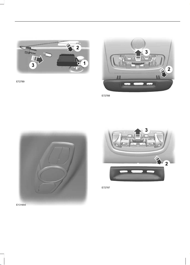
Number plate lamp
3
2
1
E72789
1. Carefully release the spring clip.
2. Remove the lamp.
3. Remove the bulb.
Interior lamps
Vehicles with LED lamps
Note: These are not serviceable items,
please consult your dealer if they fail.
E131655
Vehicles without interior sensors
3
2
E72788
1. Carefully prise out the lens.
2. Remove the lens.
3. Remove the bulb.
Vehicles with interior sensors
2
3
E72787
1. Carefully prise out the lens.
2. Remove the lens.
3. Remove the bulb.
67
Lighting
Page 70

Reading lamps
Vehicles without interior sensors
33
2
E72796
1. Carefully prise out the lens.
2. Remove the lens.
3. Remove the bulb.
Vehicles with interior sensors
22
1
E72786
1. Carefully prise out the lamp.
2. Turn the bulb holder anti-clockwise
and remove it.
E73939
3
3. Remove the bulb.
Vanity mirror lamp
E72785
1. Carefully prise out the lamp.
2. Remove the bulb.
68
Lighting
Page 71

Luggage compartment lamp
E72784
1. Carefully prise out the lamp.
2. Remove the bulb.
BULB SPECIFICATION CHART
Power (watt)SpecificationLamp
21PY21WFront direction indicator
55H1Headlamp main beam
55H7Headlamp dipped beam
55H1Cornering lamp
5W5WSide repeater
5W5WApproach lamp
35H8Front fog lamp
5W5WSide lamp
21PY21WRear direction indicator
21H21WRear fog lamp
21P21WReversing lamp
5W5WNumber plate lamp
10FestoonInterior lamp
5BA9sReading lamp
5W5WVanity mirror lamp
69
Lighting
Page 72

Power (watt)SpecificationLamp
6W6WLuggage compartment lamp
70
Lighting
Page 73

POWER WINDOWS
WARNING
Do not operate the electric windows
unless they are free from obstruction.
Note: If you operate the switches often
during a short period of time, the system
might become inoperable for a certain time
to prevent damage due to overheating.
Note: You can operate the windows for
several minutes after you switch off the
ignition. They will be deactivated as soon
as a door is opened.
Note: If you operate both the switch on the
relevant door and the switch for that
window on the driver’s door at the same
time, the window will stop moving.
Switch on the ignition to operate the
electric windows.
Global opening and global closing
You can also operate the electric windows
with the ignition off via the global opening
and global closing function. See Global
Opening and Closing (page 39).
Note: Global opening and global closing
will open or close the windows
automatically only on vehicles equipped
with four electric windows.
Note: Global closing will only operate if you
have set the memory correctly for each
window.
Driver’s door switches
E121510
You can operate all the windows with the
switches on the door trim panel of the
driver’s door.
Front and rear passengers’ door
switches
E70849
Opening and closing the windows
automatically
Press or lift the switch to the second action
point and release it. Press or lift it again to
stop the windows.
71
Windows and Mirrors
Page 74

Safety switch for rear windows
WARNING
On some vehicles, pressing the
switch will also lock the rear doors
from inside. See Child Safety
Locks (page 27).
Note: You can always operate the rear
windows from the driver’s door.
E121511
A switch in the driver’s door disables the
rear electric window switches.
The light in the switch illuminates and the
lights in the rear window switches go off
when the rear windows are disabled.
Anti-trap function
WARNING
Careless closing of the windows can
override the protection function and
cause injuries.
The electric windows will stop
automatically while closing and reverse
some distance if there is an obstacle in the
way.
Overriding the anti-trap function
CAUTION
While you close the window for the
third time, the anti-trap function is
disabled. Make sure there are no
obstacles in the way of the closing window.
To override this protection function when
there is a resistance, for example, in the
winter, proceed as follows:
1. Close the window twice until it reaches
the resistance and let it reverse.
2. Close the window a third time to the
resistance. The anti-trap function is
disabled and you cannot close the
window automatically. The window
will override the resistance and you can
close it fully.
3. If the window does not close after the
third attempt, have it checked by a
properly trained technician.
Resetting the memory of the
electric windows
WARNING
The anti-trap function is deactivated
until you have reset the memory.
After the battery has been disconnected
from the vehicle you must reset the
memory separately for each window:
1. Lift the switch until the window is fully
closed. Hold the switch lifted for one
more second.
2. Release the switch and lift it again, two
or three times, for one more second.
3. Open the window and try to close it
automatically.
4. Reset and repeat procedure if the
window does not close automatically.
72
Windows and Mirrors
Page 75

Safety mode
WARNING
The anti-trap function is not active
during this procedure.
If the system detects a malfunction, it
enters a safety mode. The windows will
move for only about 0.5 seconds at a time
and then stop again. Close the windows
by pressing the switch again when the
windows stop moving. Have this checked
immediately.
EXTERIOR MIRRORS
WARNING
Do not overestimate the distance of
the objects that you see in the
convex mirror. Objects seen in
convex mirrors will appear smaller and
further away than they actually are.
Manual folding mirrors
Folding
Push the mirror towards the door window
glass.
Unfolding
Make sure that you fully engage the mirror
in its support when returning it to its
original position.
ELECTRIC EXTERIOR MIRRORS
A C
B
E70846
Left-hand mirrorA
OffB
Right-hand mirrorC
Mirror tilting positions
E70847
The electric exterior mirrors are fitted with
a heating element that will defrost or
demist the mirror glass. See Heated
Windows and Mirrors (page 111).
73
Windows and Mirrors
Page 76

Electric folding mirrors
Automatic folding and unfolding
Note: If the mirrors have been folded using
the manual fold button they can only be
unfolded using the manual fold button.
The mirrors will fold automatically when
you lock the vehicle with the key, the
remote control or a keyless entry system
request. The mirrors will unfold when you
unlock the vehicle with the key, the remote
control, a keyless entry system request,
the driver's interior door handle or starting
the engine.
Manual folding and unfolding
The electric folding mirrors operate with
the ignition on.
Note: You can operate the mirrors (mirror
tilting and folding) for several minutes after
you switch off the ignition. They will be
deactivated as soon as a door is opened.
E72623
Press the button to fold or unfold the
mirrors.
If you press the switch again while the
mirrors are moving, they will stop and
reverse the direction of movement.
Note: When the mirrors are operated often
during a short period of time, the system
may become inoperable for a period of time
to prevent damage due to overheating.
Reverse mirror dipping
Depending on the switch position (A or C),
the relevant exterior mirror will dip
whenever you select reverse gear, giving
you a view of the kerb.
Note: You can disable this feature by
leaving the switch in position B.
The exterior mirror will return to the original
position:
• If the vehicle speed exceeds 10 km/h
(6 mph).
• Approximately 10 seconds after reverse
gear has been disengaged.
• If the switch is returned to position B.
When you first use this feature, the mirror
will dip to a preset position. This position
can be adjusted using the following
sequence:
1. Turn the ignition on. Do not start the
engine.
2. Select the desired exterior mirror (A or
C).
3. Select reverse gear, the selected
exterior mirror will adjust to a preset
position.
4. Adjust the mirror to the required dipped
position.
5. Disengage reverse gear or press and
hold the desired memory pre-set
button until a single chime sounds to
confirm. See Memory Function (page
128).
The settings will be stored automatically.
74
Windows and Mirrors
Page 77

AUTO-DIMMING MIRROR
E71028
The auto-dimming mirror will adjust
automatically when hit by glaring light
from behind. It will not work when you have
selected reverse gear.
BLIND SPOT MONITOR
Blind spot information system
(BLIS)
WARNINGS
The system is not designed to
prevent contact with other vehicles
or objects. The system only provides
a warning to assist you in detecting
vehicles in the blind spot zones. The
system will not detect obstacles,
pedestrians, motorcyclists or cyclists.
Do not use the system as a
replacement for using the side and
rear view mirrors, and looking over
your shoulder before changing lanes. The
system is not a replacement for careful
driving and is only to be used as an aid.
The system is a convenience feature that
aids the driver in detecting vehicles that
may have entered the blind spot zone (A).
The detection area is on both sides of the
vehicle extending rearwards from the
exterior mirrors to approximately 3 metres
(10 feet) beyond the bumper. The system
will alert you if certain vehicles enter the
blind spot zone whilst driving.
A
A
E124788
Using the system
The system displays a yellow indicator
located in the exterior mirrors.
E124736
Note: Both indicators will illuminate briefly
when you switch the ignition on to confirm
that the system is operational.
Note: On vehicles with automatic
transmission, the system is active only in S,
D and N.
The system is only active when you exceed
10 km/h (6 mph). The system is
temporarily deactivated when you select
reverse gear.
75
Windows and Mirrors
Page 78
System detection and alerts
The system will trigger the alert for vehicles
that enter the blind spot zone from the rear
or merge from the side. Vehicles that you
pass, or vehicles that enter the blind spot
zone from the front, will only trigger the
alert after the vehicle has remained in the
blind spot zone for a short period of time.
Note: Vehicles that pass through the blind
zone quickly (typically less than 2 seconds)
will not trigger the alert.
The system consists of two radar sensors
each located behind the rear wheels
hidden behind the bumpers.
CAUTIONS
Do not place items such as bumper
stickers in this area.
Repairs to these areas using body filler
will affect the performance of the
system.
E124741
Detection limitations
There may be certain instances where
vehicles entering and exiting the blind spot
zones may not be detected.
Instances which may cause non-detection:
• Debris build up on the rear bumper
panels in the area of the sensors.
• Certain manoeuvring of vehicles
entering and exiting the blind zone.
• Vehicles passing through the blind zone
at high speed.
• Severe weather conditions.
• Several vehicles passing through the
blind zone following each other closely.
False alerts
Note: False alerts are temporary and will
self correct.
There may be certain instances when the
system will alert with no vehicle present in
the blind zone.
Circumstances where false alerts may
occur:
• Road guardrails.
• Motorway concrete walls.
• Construction areas.
• Sharp turns around a building.
• Bushes and trees.
• Cyclists and motorcyclists.
• Coming to a stop with a vehicle directly
behind but very close.
Turning the system on and off
Note: The on or off position will remain until
manually changed.
You can turn the system on and off using
the information display. See Information
Displays (page 84).
When you turn the system off no further
alerts will be received. The BLIS warning
indicator will illuminate. See Warning
Lamps and Indicators (page 80).
Detection errors
Note: The alert indicator in the mirror will
not illuminate.
76
Windows and Mirrors
Page 79

If the system senses a fault on either
sensor, the system warning symbol will
illuminate and remain on. The information
display will confirm the fault and indicate
whether the left or right side is affected.
Blocked sensor
WARNING
Prior to the system recognizing a
blocked condition and issuing a
warning, the number of missed
objects will increase.
CAUTION
The sensors may not detect vehicles
in heavy rain or other conditions that
cause disruptive reflections.
Note: Keep the rear bumper area
surrounding the sensors free from dirt, ice
and snow.
If a sensor becomes blocked the system
performance may degrade. A blocked
sensor message may be displayed.
The system will automatically return to
normal operation once two other vehicles
have been detected on both sides.
Trailer towing false alerts
CAUTION
Vehicles fitted with a trailer tow
module not approved by us may not
correctly be detected. Switch the
system off to avoid false alerts. See
Information Displays (page 84).
If the vehicle is fitted with a trailer tow
module approved by us, the system will
detect a connected trailer and deactivate.
A confirmation message will be shown in
the information display. See Information
Messages (page 97). The BLIS warning
indicator will illuminate. See Warning
Lamps and Indicators (page 80).
77
Windows and Mirrors
Page 80

GAUGES
Type 1 and 2
BA C D
E72984
TachometerA
Engine coolant temperature gaugeB
Fuel gaugeC
SpeedometerD
78
Instrument Cluster
Page 81

Type 3
A
B
C
D
E
E130765
TachometerA
SpeedometerB
Engine coolant temperature gaugeC
Fuel gaugeD
Message centre. See Information Displays (page 84).E
Engine coolant temperature gauge
Note: On type 3 this gauge is shown within
the message centre and will not be
displayed unless required. See Information
Displays (page 84).
Shows the temperature of the engine
coolant. At normal operating temperature,
the indicator will remain in the centre
section.
CAUTION
Do not restart the engine until the
cause of overheating has been
resolved.
If the indicator moves towards 120°C, the
engine is overheating. Stop the engine,
switch the ignition off and determine the
cause once the engine has cooled down.
See Engine Coolant Check (page 219).
79
Instrument Cluster
Page 82

Fuel gauge
Note: On type 3 this gauge is shown within
the message centre.
The arrow adjacent to the fuel pump
symbol tells you on which side of your
vehicle the fuel filler cap is located.
WARNING LAMPS AND INDICATORS
The following warning lamps and
indicators will illuminate briefly when you
switch the ignition on to confirm that the
system is operational:
• ABS
• Airbag
• Blind spot monitor
• Brake system
• Coolant temperature
• Engine
• Frost
• Ignition
• Oil pressure
• Stability control (ESP).
If a warning or indicator lamp does not
illuminate when the ignition is switched
on, it indicates a malfunction. Have the
system checked by properly trained
technician.
ABS warning lamp
If it illuminates when you are
driving, this indicates a
malfunction. You will continue
to have normal braking (without ABS).
Have the system checked by a properly
trained technician as soon as possible.
Airbag warning lamp
If it illuminates when you are
driving, this indicates a
malfunction. Have the system
checked by a properly trained technician.
Blind spot monitor indicator
E124823
It will illuminate when this
feature is switched off or in
conjunction with a message.
See Blind Spot Monitor (page 75). See
Information Messages (page 97).
Brake system lamp
It illuminates when the parking
brake is engaged.
WARNING
Reduce your speed gradually and
stop your vehicle as soon as it is safe
to do so. Use your brakes with care.
If it illuminates when you are driving, check
that the parking brake is not engaged. If
the parking brake is not engaged, this
indicates a malfunction. Have the system
checked by a properly trained technician
immediately.
Coolant temperature warning
lamp
CAUTION
Do not resume your journey if it
illuminates despite the level being
correct. Have the system checked by
a properly trained technician immediately.
80
Instrument Cluster
Page 83

If it stays on after starting or
illuminates when driving, this
indicates a malfunction. Stop
your vehicle as soon as it is safe to do so
and switch the engine off. Check the
coolant level. See Engine Coolant Check
(page 219).
Direction indicators
Flashes during operation. A
sudden increase in the rate of
flashing warns of a failed
indicator bulb. See Changing a Bulb
(page 63).
Engine warning lamp
If it illuminates with the engine
running, this indicates a
malfunction. If it flashes when
you are driving, reduce the speed of your
vehicle immediately. If it continues to
flash, avoid heavy acceleration or
deceleration. Have the system checked by
a properly trained technician immediately.
CAUTION
If the engine warning lamp illuminates
in conjunction with a message, have
the system checked as soon as
possible.
Forward alert indicator
E124824
It will illuminate when this
feature is switched off. See
Forward alert function (page
171).
Front fog lamp indicator
It will illuminate when you switch
the front fog lamps on.
Frost warning lamp
WARNING
Even if the temperature rises to
above 4ºC (39.2°F) there is no
guarantee that the road is free of
hazards caused by inclement weather.
It will illuminate and glow orange
when the outside air
temperature is between 4ºC
(39.2ºF) and 0ºC (32ºF). It will glow red
when the temperature is below 0ºC
(32ºF).
Glow plug indicator
See Starting a Diesel Engine
(page 135).
Headlamp indicator
It will illuminate when you switch
the headlamp dipped beam or
the side and tail lamps on.
Ignition warning lamp
If it illuminates when you are
driving, this indicates a
malfunction. Switch off all
unnecessary electrical equipment. Have
the system checked by a properly trained
technician immediately.
Lane departure warning indicator
It will illuminate when this
feature is switched off or in
conjunction with a message. The
indicator will go out when you switch the
system back on or when you switch the
ignition off. See Lane Departure Warning
(page 176). See Information Messages
(page 97).
81
Instrument Cluster
Page 84

Low fuel level warning lamp
If it illuminates, refuel as soon as
possible.
Main beam indicator
It will illuminate when you switch
the headlamp main beam on. It
will flash when you use the
headlamp flasher.
Message indicator
It will illuminate when a new
message is stored in the
information display. See
Information Messages (page 97).
Oil pressure warning lamp
CAUTION
Do not resume your journey if it
illuminates despite the level being
correct. Have the system checked by
a properly trained technician immediately.
If it stays on after starting or
illuminates when driving, this
indicates a malfunction. Stop
your vehicle as soon as it is safe to do so
and switch the engine off. Check the engine
oil level. See Engine Oil Check (page 219).
Rear fog lamp indicator
It will illuminate when you switch
the rear fog lamps on.
Seat belt reminder
See Seat belt reminder (page
32).
Shift indicator
It will illuminate to inform you
that shifting to a higher gear may
give better fuel economy and
lower CO2 emissions. It will not illuminate
during periods of high acceleration, braking
or when the clutch pedal is pressed.
Stability control (ESP) warning
lamp
While driving, it flashes during
activation of the system. After
switching on the ignition, if it
does not illuminate or illuminates
continuously while driving, this indicates a
malfunction. During a malfunction, the
system switches off. Have the system
checked by a properly trained technician
as soon as possible.
If you switch ESP off, the warning lamp will
illuminate. The lamp will go out when you
switch the system back on or when you
switch the ignition off.
Start-stop indicator
It will illuminate to inform you
when the engine shuts down or
in conjunction with a message.
See Using start-stop (page 138). See
Information Messages (page 97).
AUDIBLE WARNINGS AND INDICATORS
Switching the chimes on and off
You can deactivate certain chimes.
To set which chimes should sound:
82
Instrument Cluster
Page 85

E70499
1. Press the right arrow button on the
steering wheel to enter the main menu.
2. Highlight Setup with the up and down
arrow buttons and press the right arrow
button.
3. Highlight Chimes and press the right
arrow button.
4. Highlight the chime and press the OK
button to switch the chime on and off.
5. Press the left arrow button to exit the
menu. Press and hold the left arrow
button to return to the main menu
display.
83
Instrument Cluster
Page 86

GENERAL INFORMATION
WARNING
Do not operate the information
display controls when the vehicle is
moving.
Note: The information display will remain
on for several minutes after you switch off
the ignition.
Various systems on your vehicle can be
controlled using the buttons on your
steering wheel. Corresponding information
is displayed in the information display.
For detailed instructions on audio,
navigation, phone etc. refer to the
appropriate manual.
Controls
E70499
Press the up and down arrow buttons:
• to scroll through the trip computer
displays
• to scroll through and highlight the
options within a menu.
Press the right arrow button:
• to enter the main menu from the trip
computer displays
• to enter a sub-menu.
Press the left arrow button to exit a menu.
Hold the left arrow button pressed at any
time to return to the main menu display
(escape button).
Note: The system will return to the trip
computer displays automatically if you do
not press any button for a period of time.
Press the OK button to choose and
confirm a setting.
Instrument cluster functions
Type 3Type 2Type 1Function
XXXTrip computer
XXXInformation messages
XXXClock setup
XX-Display settings
XX-Park heater setup
84
Information Displays
Page 87
Type 3Type 2Type 1Function
X--Navigation control
X--CD control
X--CD changer control
X--Radio control
X--Phone control
X--Auxiliary input control
Type 1
E80604
Press the up and down arrow buttons on
the steering wheel to scroll through the trip
computer displays. See Trip Computer
(page 93).
85
Information Displays
Page 88

Menu structure
Information
Reset trip
BLIS
ECO MODE
Trip Odo
Avg Fuel
Avg Speed
All values
Messages
Auto StartStop
Gear Shifting
Anticipation
Speed
For more Info
Clock
Set Clock
24 Hour Mode
12 Hour Mode
E131626
Type 2
E74426
6.3
Average Fuel
09:00
234.2 km
123456 km
l
100km
Press the up and down arrow buttons on
the steering wheel to scroll through the trip
computer displays. See Trip Computer
(page 93).
86
Information Displays
Page 89

Menu structure
Reset Trip
BLIS
ESP
Trip Odo
Avg fuel
Avg speed
All
Gear shifting
Anticipation
Speed
For more Info
English
Deutsch
Italiano
Français
Español
Türkçe
Pyccкий
Nederlands
Polski
Português
Svenska
Configure
Language
Measure unit
Display
Set Clock
24 Hour Mode
12 Hour Mode
Always off
On guidance
Always on
Messages
Tyre Press.
Auto StartStop
Metric
Imperial
Help Screen
Radio Info
Phone Info
NAV info
Information
Clock
Setup
ECO MODE
BA
E131627
87
Information Displays
Page 90

Chimes
Forw Alert
Low Fuel
Home light
General warn.
General info.
Low
Off
High
Normal
Off
Manual
Auto
Hill Launch
Check
High load
Low load
Tyre Pressure
Full guard
Ask on exit
Reduced
Alarm
Aux. Heater
Parkheater
BA
E87753
Set Time
Saturday
Sunday
Friday
Thursday
Monday
Tuesday
Wednesday
Set Time
Saturday
Sunday
Friday
Thursday
Monday
Tuesday
Wednesday
Time 1
Time 2
Once
Active now
88
Information Displays
Page 91

Type 3
E88048
Use the controls to scroll through the menu
displays.
Device list
The highlighted icon shows the current
menu in use.
Navigation
CD
CD changer
Radio
Phone
Trip computer
Settings
Auxiliary input
89
Information Displays
Page 92

Menu structure
CD
Navigation
Home
Destinat. mem.
Destinat. A-Z
Last destinat.
Cancel guidan.
Destinations
Destinations
Destinations
Folder / Tracks
Folder / Tracks
Folder / Tracks
Folder / Tracks
Folder / Tracks
Folder / Tracks
Folder / Tracks
Stations
Stations
Stations
Stations
Stations
Stations
Stations
Numbers
Numbers
Numbers
Station list
FM 1 / FM
FM 2
FM 3
FM - AST
MW / AM
LW / AM-AST
CD changer
CD 1
CD 2
CD 3
CD 4
CD 5
CD 6
Radio
Phone book
Redial
Incoming calls
Outgoing calls
Call status
Phone
A
E131628
Trip computer
Distance to empty
Average fuel
Average speed
Reset selected element
Reset trip odometer
90
Information Displays
Page 93
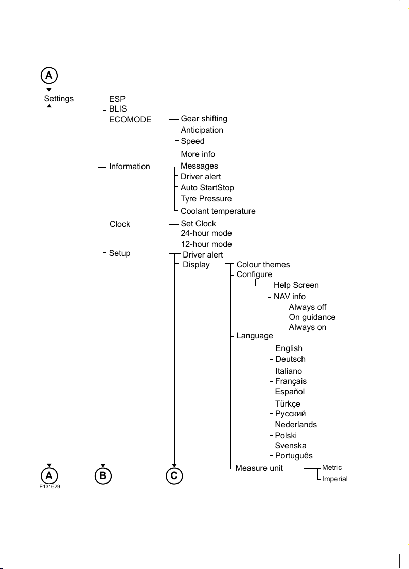
English
Colour themes
Configure
Language
Measure unit
Display
Driver alert
Set Clock
24-hour mode
12-hour mode
Gear shifting
Anticipation
Speed
More info
Always off
On guidance
Always on
Messages
Tyre Pressure
Coolant temperature
Driver alert
Auto StartStop
Metric
Imperial
Help Screen
NAV info
Settings
Information
Clock
Setup
ESP
BLIS
ECOMODE
A
CB
E131629
A
Deutsch
Italiano
Français
Español
Türkçe
Pyccкий
Nederlands
Polski
Português
Svenska
91
Information Displays
Page 94

Chimes
Low Fuel
Home light
General warn.
General info.
Forw Alert
Low
Normal
High
Off
Lane depart
Sensitivity
Normal
High
Intensity
High
Normal
Low
Off
Manual
Auto
Hill Launch
Check
High load
Low load
Tyre Pressure
Full guard
Ask on exit
Reduced
Alarm
Aux Heater
Auto beam
On
Sensitivity
High
Normal
Low
C
E131630
92
Information Displays
Page 95

Set Time
Saturday
Sunday
Wednesday
Tuesday
Friday
Thursday
Monday
Set Time
Saturday
Sunday
Wednesday
Tuesday
Friday
Thursday
Monday
Time 1
Time 2
Once
Active now
Park heater
Auxiliary input
BA
E88067
TRIP COMPUTER
Odometer
Registers the total mileage of the vehicle.
Tripmeter
Registers the mileage of individual
journeys.
Distance to empty
Indicates the approximate distance the
vehicle will travel on the fuel remaining in
the tank. Changes in driving pattern may
cause the value to vary.
Average fuel consumption
Indicates the average fuel consumption
since the function was last reset.
Average speed
Indicates the average speed calculated
since the function was last reset.
Outside air temperature
Shows the outside air temperature.
93
Information Displays
Page 96
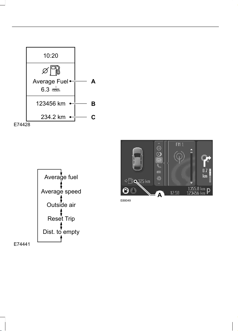
Type 1 and 2
E74428
6.3
Average Fuel
10:20
234.2 km
123456 km
l
100km
A
B
C
A. Trip computer
B. Odometer
C. Tripmeter
The trip computer includes the following
information displays:
Average fuel
Average speed
Outside air
Reset Trip
Dist. to empty
E74441
Press the up and down arrow buttons on
the steering wheel to scroll through the trip
computer displays.
Note: The position of the trip computer
display may vary depending on the
information shown in the display.
Resetting the trip computer using the
main menu
To reset a particular display:
1. Press the right arrow button on the
steering wheel to enter the main menu.
2. Highlight Reset Trip with the up and
down arrow buttons and press the right
arrow button.
3. Highlight the function to be reset.
4. Press the right arrow button to select
the function.
5. Hold the OK button pressed.
To reset all three displays, select All
values and hold the OK button pressed.
Type 3
E88049
A
Trip computerA
Press the OK button on the steering wheel
to cycle through the different trip computer
displays. To reset a value, press and hold
the OK button.
Resetting the trip computer using the
main menu
To reset a particular display:
1. Highlight Trip Computer with the up
and down arrow buttons and press the
right arrow button.
2. Highlight the function to be reset.
94
Information Displays
Page 97

3. Hold the OK button pressed.
PERSONALISED SETTINGS
The following information is displayed in
the information display if you have
selected it:
Help screen, radio, navigation and
phone information
The help screen appears for a few seconds
when you switch the ignition on.
If the radio, navigation or telephone is
operating, information relating to this
system is displayed in the information
display.
To select which information is displayed
in the information display:
Type 1 and 2
1. Press the right arrow button on the
steering wheel to enter the main menu.
2. Highlight Setup with the up and down
arrow buttons and press the right arrow
button.
3. Highlight Display and press the right
arrow button.
4. Highlight Configure and press the right
arrow button.
5. To toggle the Help screen, Radio Info
and Phone Info on and off, highlight
the desired setting and press the OK
button to confirm the setting.
6. Press the left arrow button to exit the
menu. Hold the left arrow button
pressed to return to the trip computer
display.
Type 3
1. Highlight Settings with the up and
down arrow buttons and press the right
arrow button.
2. Highlight Setup with the up and down
arrow buttons and press the right arrow
button.
3. Highlight Display and press the right
arrow button.
4. Highlight Configure and press the right
arrow button.
5. To toggle the Help screen and NAV
Info on and off, highlight the desired
setting and press the OK button to
confirm the setting.
Navigation information
You can also choose when the navigation
information is displayed in the information
display. Three options are available:
• Always off: No navigation information
is displayed in the information display.
• On guidance: The navigation
information will only appear when the
navigation system provides a guidance
instruction. This function is only
available on certain navigation
systems.
• Always on: Navigation information will
always appear in the information
display when the navigation system is
operating.
To set when navigation information should
be displayed:
Type 1 and 2
1. Press the right arrow button on the
steering wheel to enter the main menu.
2. Highlight Setup with the up and down
arrow buttons and press the right arrow
button.
3. Highlight Display and press the right
arrow button.
4. Highlight Configure and press the right
arrow button.
5. Highlight Nav Info and press the right
arrow button.
95
Information Displays
Page 98

6. Highlight the desired setting and press
the OK button to confirm the setting.
7. Press the left arrow button to exit the
menu. Hold the left arrow button
pressed to return to the trip computer
display.
Type 3
1. Highlight Settings with the up and
down arrow buttons and press the right
arrow button.
2. Highlight Setup with the up and down
arrow buttons and press the right arrow
button.
3. Highlight Display and press the right
arrow button.
4. Highlight Configure and press the right
arrow button.
5. Highlight Nav Info and press the right
arrow button.
6. Highlight the desired setting and press
the OK button to confirm the setting.
Language
A choice of eleven languages are available:
English, German, Italian, French, Spanish,
Turkish, Russian, Dutch, Polish, Swedish
and Portuguese.
Type 1 and 2
1. Press the right arrow button on the
steering wheel to enter the main menu.
2. Highlight Setup with the up and down
arrow buttons and press the right arrow
button.
3. Highlight Display and press the right
arrow button.
4. Highlight Language and press the right
arrow button.
5. Highlight the desired setting and press
the OK button to confirm the setting.
6. Press the left arrow button to exit the
menu. Hold the left arrow button
pressed to return to the trip computer
display.
Type 3
1. Highlight Settings with the up and
down arrow buttons and press the right
arrow button.
2. Highlight Setup with the up and down
arrow buttons and press the right arrow
button.
3. Highlight Display and press the right
arrow button.
4. Highlight Language and press the right
arrow button.
5. Highlight the desired setting and press
the OK button to confirm the setting.
Units of measure
Note: The outside air temperature is only
displayed in degrees Celsius and cannot be
set to degrees Fahrenheit.
To select metric or imperial units:
Type 1 and 2
1. Press the right arrow button on the
steering wheel to enter the main menu.
2. Highlight Setup with the up and down
arrow buttons and press the right arrow
button.
3. Highlight Display and press the right
arrow button.
4. Highlight Measure Unit and press the
right arrow button.
5. Highlight the desired setting and press
the OK button to confirm the setting.
6. Press the left arrow button to return to
exit the menu. Hold the left arrow
button pressed to return to the trip
computer display.
96
Information Displays
Page 99

Type 3
1. Highlight Settings with the up and
down arrow buttons and press the right
arrow button.
2. Highlight Setup with the up and down
arrow buttons and press the right arrow
button.
3. Highlight Display and press the right
arrow button.
4. Highlight Measure Unit and press the
right arrow button.
5. Highlight the desired setting and press
the OK button to confirm the setting.
INFORMATION MESSAGES
E70499
Press OK to acknowledge and remove
some messages from the information
display. Other messages will be removed
automatically after a short time.
With instrument cluster type 3, certain
messages need to be confirmed before
you can access the menus.
Message indicator
The message indicator
illuminates to supplement some
messages. It will be red or amber
depending on the severity of the message
and will remain on until the cause of the
message has been rectified.
Message symbols
See Owner’s handbook.
Have the system checked at the
next service.
Have the system checked as
soon as possible.
Stop your vehicle as soon as it is
safe to do so.
Viewing current messages
Type 1 and 2
1. Press the right arrow button on the
steering wheel to enter the main menu.
2. Highlight Information with the up and
down arrow buttons and press the right
arrow button.
3. Highlight Messages and press the right
arrow button.
4. Use the up and down buttons to view
the current messages.
Type 3
1. Press the right arrow button on the
steering wheel to enter the main menu.
2. Highlight Settings with the up and
down arrow buttons and press the right
arrow button.
3. Highlight Information with the up and
down arrow buttons and press the right
arrow button.
4. Highlight Messages and press the right
arrow button.
5. Use the up and down buttons to view
the current messages.
97
Information Displays
Page 100

Active suspension
ActionIndicatorMessage
Have the system checked by a properly trained
technician.
amberIVDC malfunction
See Active suspension (page 158).-IVDC comfort
See Active suspension (page 158).-IVDC normal
See Active suspension (page 158).-IVDC sport
Airbag
ActionIndicatorMessage
Have the system checked by a properly trained
technician as soon as possible.
amberAirbag malfunction
Alarm
ActionIndicatorMessage
See Alarm (page 45).amberAlarm triggered
Have the system checked by a properly trained
technician.
-Alarm system
service reqd.
Automatic main beam control, Lane departure warning and Driver alert
ActionIndicatorMessage
Stop and rest as soon as it is safe to do so.redDriver fatigue
Rest now
The front camera sensor has reduced visibility.
Clean the windscreen.
amberFront camera
Clean screen
The front camera sensor has malfunctioned.
Have this checked as soon as possible.
amberFront camera
malfunction
The affected systems are temporarily unavail-
able, and should resume after a few minutes.
amberFront camera
not available
Take a rest break soon.amberDriver fatigue
Rest suggested
98
Information Displays
 Loading...