

Page 1

Feel the difference
FordMondeo
Owner's handbook
Page 2

The information contained in this publication was correct at the time of going to print. In the interest of
development the right is reserved to change specifications, design or equipment at any time without
notice and without incurring any obligations. This publication, or part thereof, may not be reproduced
nor translated without our approval. Errors and omissions excepted.
© Ford Motor Company 2008
All rights reserved.
Part number: 8S7J-19A321-DA (CG3536en) 06/2008 20080714084638
Page 3

Introduction
About this handbook................................5
Symbols glossary......................................5
Parts and accessories..............................6
Quick start
Quick start..................................................8
Child safety
Child seats................................................16
Booster cushions.....................................17
Child seat positioning..............................19
ISOFIX anchor points...............................21
Child safety locks....................................23
Occupant protection
Principle of operation..............................24
Fastening the seat belts........................26
Seat belt height adjustment..................26
Seat belt reminder...................................27
Using seat belts during pregnancy......27
Disabling the passenger airbag............27
Keys and remote controls
Using the key...........................................29
General information on radio
frequencies..........................................29
Programming the remote control........29
Changing the remote control
battery...................................................30
Locks
Locking and unlocking...........................33
Global opening and closing...................35
Keyless entry...........................................37
Engine immobiliser
Principle of operation..............................40
Coded keys.............................................40
Arming the engine immobiliser.............40
Disarming the engine immobiliser........40
Alarm
Principle of operation..............................41
Arming the alarm.....................................43
Disarming the alarm................................43
Steering wheel
Adjusting the steering wheel.................44
Audio control...........................................44
Wipers and washers
Windscreen wipers.................................46
Autowipers...............................................46
Windscreen washers..............................47
Rear window wiper and washers.........47
Headlamp washers................................48
Checking the wiper blades...................48
Changing the wiper blades...................48
Lighting
Lighting control........................................50
Autolamps.................................................51
Front fog lamps........................................51
Rear fog lamps.........................................51
Headlamp levelling...................................51
Hazard warning flashers........................53
Adaptive front lighting system
(AFS)......................................................53
Direction indicators.................................55
Interior lamps...........................................55
Removing a headlamp...........................56
Changing a bulb......................................57
Bulb specification chart..........................64
Windows and mirrors
Electric windows.....................................66
Exterior mirrors........................................68
Electric exterior mirrors..........................68
1
Table of contents
Page 4

Interior mirror...........................................69
Auto-dimming mirror..............................70
Instruments
Gauges......................................................71
Warning lamps and indicators...............73
Audible warnings and indicators...........75
Information displays
General information................................76
Trip computer..........................................85
Personalised settings.............................87
Information messages...........................89
Climate control
Principle of operation..............................97
Air vents....................................................97
Manual climate control...........................98
Automatic climate control....................100
Heated windows and mirrors..............103
Auxiliary heater.......................................103
Electric sunroof......................................106
Seats
Sitting in the correct position...............109
Manual seats..........................................109
Electric seats...........................................110
Head restraints.......................................112
Rear seats...............................................112
Heated seats..........................................113
Ventilated seats......................................113
Convenience features
Sun blinds................................................115
Instrument lighting dimmer...................115
Clock........................................................115
Cigar lighter.............................................115
Ashtray.....................................................116
Auxiliary power sockets........................116
Cup holders.............................................117
Glove box................................................117
Storage compartments.........................117
Map pockets...........................................118
Memory function....................................118
Glasses holder........................................119
CD changer.............................................119
Auxiliary input (AUX IN) socket.............119
USB port.................................................120
Starting the engine
General information...............................121
Ignition switch.........................................121
Keyless starting......................................121
Steering wheel lock...............................123
Starting a petrol engine........................123
Starting a petrol engine - Flexible
Fuel.......................................................124
Starting a diesel engine........................125
Diesel particulate filter (DPF)................125
Switching off the engine.......................126
Engine heater.........................................126
Fuel and refuelling
Safety precautions................................127
Fuel quality - Petrol................................127
Fuel quality - Flexible Fuel.....................127
Fuel quality - Diesel................................127
Catalytic converter................................128
Fuel filler flap...........................................128
Refuelling................................................129
Refuelling - Flexible Fuel.......................129
Fuel consumption..................................129
Technical specifications........................130
Transmission
Manual transmission.............................132
Automatic transmission........................132
2
Table of contents
Page 5

Brakes
Principle of operation............................135
Hints on driving with ABS.....................135
Parking brake.........................................135
Stability control
Principle of operation............................136
Using stability control............................136
Hill launch assist (HLA)
Principle of operation............................137
Using HLA...............................................137
Active suspension
Principle of operation............................140
Using active suspension......................140
Parking aid
Principle of operation.............................141
Using the parking aid.............................141
Cruise control
Principle of operation............................143
Using cruise control..............................143
Adaptive cruise control
(ACC)
Principle of operation............................145
Using ACC..............................................146
Forward alert function..........................149
Load carrying
General information...............................151
Luggage anchor points.........................151
Sliding loadspace floor..........................152
Rear under floor storage......................153
Cargo nets..............................................154
Luggage covers....................................155
Roof racks and load carriers...............155
Dog guard...............................................156
Load retaining fixtures..........................157
Towing
Towing a trailer.......................................160
Detachable tow ball..............................160
Driving hints
Running-in..............................................164
General driving points - Sports
Suspension.........................................164
Emergency equipment
First aid kit...............................................165
Warning triangle.....................................165
Status after a collision
Inspecting safety system
components.......................................167
Fuses
Fuse box locations................................168
Changing a fuse.....................................170
Fuse specification chart........................171
Vehicle recovery
Towing points.........................................180
Towing the vehicle on four wheels......181
Maintenance
General information..............................182
Opening and closing the bonnet........182
Engine compartment overview - 1.6L
Duratec-16V Ti-VCT (Sigma)............184
Engine compartment overview - 2.0L
Duratec-HE (MI4)...............................185
Engine compartment overview - 2.3L
Duratec-HE (MI4)...............................186
Engine compartment overview - 2.5L
Duratec-ST (VI5).................................187
3
Table of contents
Page 6

Engine compartment overview - 1.8L
Duratorq-TDCi (Lynx) Diesel............188
Engine compartment overview - 2.0L
Duratorq-TDCi (DW) Diesel..............189
Engine compartment overview - 2.2L
Duratorq-TDCi (DW) Diesel..............190
Engine oil dipstick - 1.6L Duratec-16V
Ti-VCT (Sigma)....................................191
Engine oil dipstick - 2.0L Duratec-HE
(MI4)/2.3L Duratec-HE (MI4)............191
Engine oil dipstick - 2.5L Duratec-ST
(VI5).......................................................191
Engine oil dipstick - 1.8L Duratorq-TDCi
(Lynx) Diesel........................................191
Engine oil dipstick- 2.0L Duratorq-TDCi
(DW) Diesel/2.2L Duratorq-TDCi (DW)
Diesel...................................................192
Engine oil check.....................................192
Engine coolant check...........................192
Brake and clutch fluid check...............193
Power steering fluid check..................193
Washer fluid check................................194
Technical specifications........................194
Vehicle care
Cleaning the exterior.............................197
Cleaning the interior..............................197
Repairing minor paint damage............198
Vehicle battery
Battery care............................................199
Using booster cables............................199
Wheels and tyres
General information..............................201
Changing a road wheel........................201
Tyre repair kit.........................................205
Run flat tyres...........................................211
Tyre care.................................................212
Using winter tyres..................................212
Using snow chains................................212
Tyre pressure monitoring system.......213
Technical specifications........................214
Vehicle identification
Vehicle identification plate....................217
Vehicle identification number (VIN).....217
Technical specifications
Technical specifications........................218
Telephone
General information..............................226
Telephone setup...................................226
Bluetooth setup....................................227
Telephone controls..............................228
Using the telephone - Vehicles Without:
Navigation System............................228
Using the telephone - Navigation
System.................................................231
Voice control
Principle of operation...........................233
Using voice control...............................233
Audio unit commands.........................234
Telephone commands........................244
Navigation system commands..........249
Climate control commands................249
Connectivity
General information..............................252
Connecting an external device..........253
Using a USB device..............................253
Using an iPod........................................256
Appendices
Type approvals......................................260
Type approvals......................................260
Electromagnetic compatibility............260
4
Table of contents
Page 7
ABOUT THIS HANDBOOK
Thank you for choosing Ford. We
recommend that you take some time to
get to know your vehicle by reading this
handbook. Themore thatyou know about
it, the greater the safety and pleasureyou
will get from driving it.
Note:
This handbook describes product
features and options available throughout
the range, sometimes even before they
are generally available. It may describe
options not fitted to your vehicle.
Note:
Always use and operate your
vehicle in line with all applicable laws and
regulations.
Note:
Pass on this handbook when
selling your vehicle. It is an integral part of
the vehicle.
This vehicle has received both the
endorsement of TÜV, the accredited
international testing organisation, and
been awarded the British Allergy
Foundation’s Seal of Approval’ for its
allergy-friendly properties.
All materials used in the manufacture of
the interior of this vehicle meet strict
requirements of the TÜV TOXPROOF
Criteria Catalogue for Vehicle Interiors by
TÜV Produkt and Umwelt GmbH and are
designed to minimize the risk of allergic
reactions.
Additionally an efficient pollen filter
protects the passengers against allergen
particles in the outdoor air.
The British Allergy Foundation (BAF)
considers that these products may, in
proper use, reduce exposure to
chromium, nickel, latex, grass pollen and
other sensitizing substances and volatile
organic compounds.
Assessment carried out by Allergy UK
indicate that an individual’s exposure can
be reduced but this does not mean that
an individual’s allergic symptoms will
necessarily diminish. Allergy UK’s opinion
applies only to the products and allergens
stated.
The British Allergy Foundation’s Seal of
Approval is a European Community
registered trademark.
For more info. Contact TÜV at
www.tuv.com or the British Allergy
Foundation (Charity Reg.No.1094231) at
www.allergyuk.org or ring their English
only Helpline at UK 44-(0)-1322-619898.
SYMBOLS GLOSSARY
Symbols in this handbook
WARNING
You risk death or serious injury to
yourself and others if you do not
follow the instructions highlighted
by the warning symbol.
CAUTION
You risk damaging your vehicle if you
do not follow the instructions
highlighted by the caution symbol.
Symbols on your vehicle
When you see these symbols, read and
follow the relevant instructions in this
handbook before touching or attempting
adjustment of any kind.
5
Introduction
Page 8
PARTS AND ACCESSORIES
Now you can be sure that your
Ford parts are Ford parts
Your Ford has been built to the highest
standards using high quality Ford Original
Parts. As a result, you can enjoy driving it
for many years.
Should theunexpected occurand amajor
part needsreplacing, werecommend that
you accept nothing less than Ford Original
Parts.
The use of Ford Original Parts ensures
that your vehicle is repaired to its
pre-accident condition and maintains its
maximum residual value.
Ford Original Parts match Ford's stringent
safety requirements and high standards
of fit, finish and reliability. Quite simply, they
represent the best overall repair value,
including parts and labour costs.
Now it is easier to tell if you have really
been given Ford Original Parts. The Ford
logo is clearly visible on the following parts
if they are Ford Original Parts. If your
vehicle has to be repaired, look for the
clearly visible Ford branding and make
sure that only Ford Original Parts have
been used.
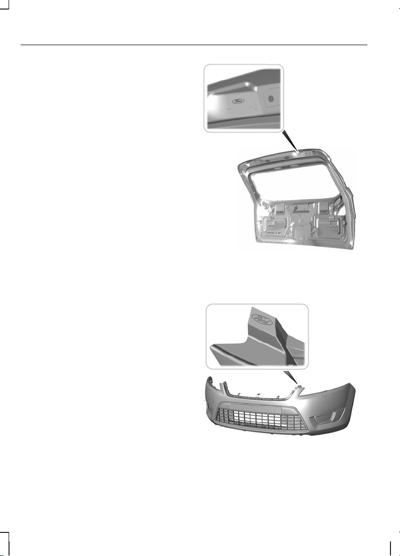
Look for the Ford logo on the
following parts
Sheet metal
•
Bonnet
•
Doors
•
Luggage compartment lid or tailgate
E88678
Bumper and radiator grille
•
Radiator grille
•
Front and rear bumper
E88505
6
Introduction
Page 9
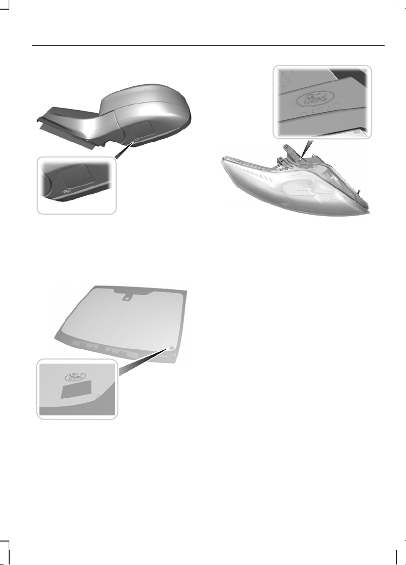
Exterior mirror
E88506
Glass
•
Rear window
•
Side glass
•
Windscreen
E88507
Lighting
•
Rear lamps
•
Headlamp
E88508
7
Introduction
Page 10
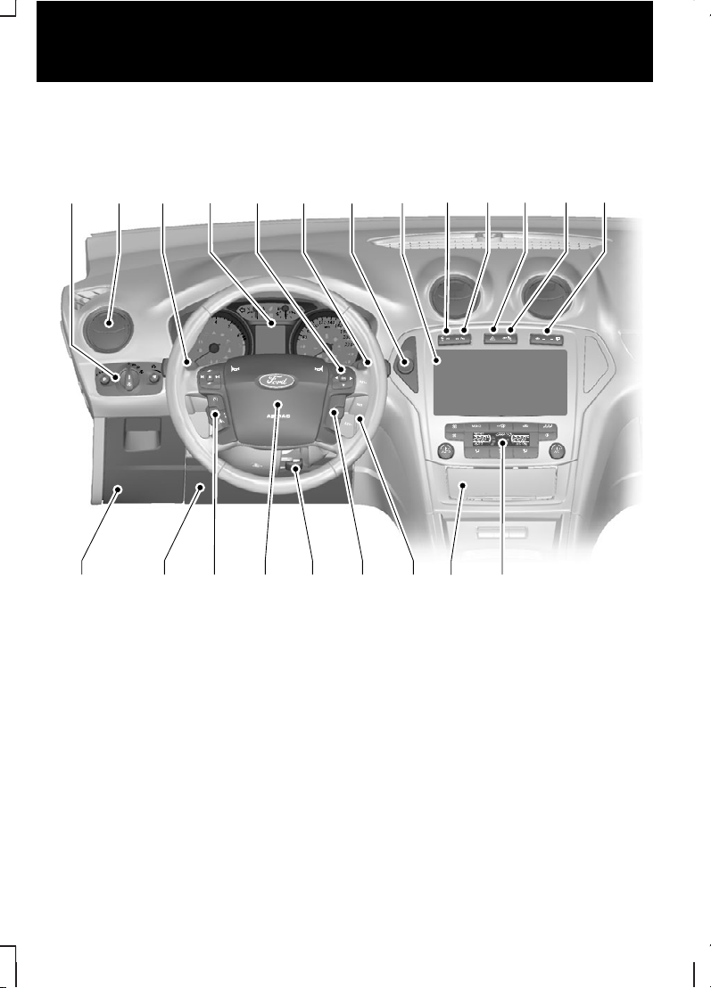
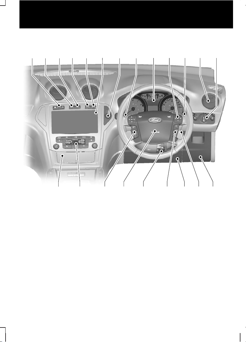
QUICK START
Instrument panel overview - left-hand drive
A
I J K L M
CB G HFE
D
V O NU T S R Q P
E87719
8
Quick start
Page 11
Instrument panel overview - right-hand drive
E87720
M
D E F B A
LK G CHJ
I
N VPT S R Q U
O
Lighting controls. See Lighting control (page 50).
A
Air vents. See Air vents (page 97).
B
Direction indicators. See Direction indicators (page 55). Telephonecontrol
buttons. See Telephone controls (page 228). Voice control buttons. See
Using voice control (page 233).
C
Instrument cluster. See Gauges (page 71).
D
Information display controls. See Information displays (page 76).
E
Wiper lever. See Windscreen wipers (page 46).
F
Start Button. See Keyless starting (page 121).
G
Audio or navigation unit. See separate handbook.H
Stability control (ESP)switch. See Using stability control (page 136).
I
9
Quick start
Page 12
Parking aid switch. See Using the parking aid (page 141).
J
Hazard warning flasher switch. See Hazard warning flashers (page 53).
K
Passenger airbagdeactivation warninglamp. See Disablingthe passenger
airbag (page 27).
L
Heated windscreen and heated rear window switches. See Heated
windows and mirrors (page 103).
M
Climate controls. See Manual climate control (page 98). See Automatic
climate control (page 100).
N
Cigar lighter. See Cigar lighter (page 115).
O
Ignition switch. See Ignition switch (page 121).
P
Cruise control switches. See Using cruise control (page 143). Adaptive
cruise control switches. See Using ACC (page 146).
Q
Steering wheel adjustment lever. See Adjusting the steering wheel (page
44).
R
Horn.S
Cruise control switches. See Using cruise control (page 143). Adaptive
cruise control switches. See Using ACC (page 146).
T
Driver Knee airbag. See Principle of operation (page 24).
U
Storage compartment. See Storage compartments (page 117).
V
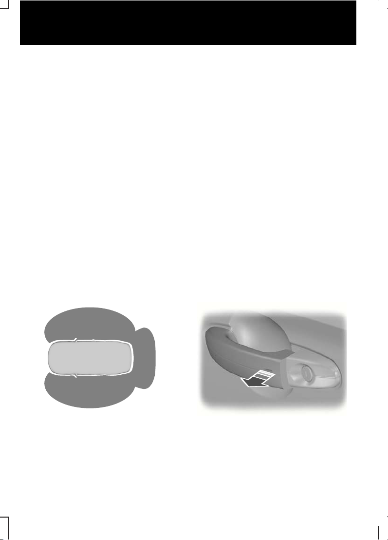
Keyless entry
E78276
Passive locking and unlocking requires a
valid passive key to be located within one
of the three external detection ranges.
Unlocking the vehicle
E78278
Pull a door handle to unlock all the doors
and the luggage compartment lid and
disarm the alarm.
10
Quick start
Page 13
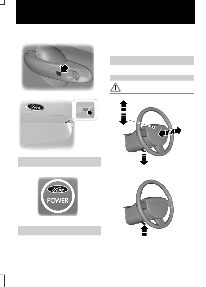
Locking the vehicle
E87384
E87435
See Keyless entry (page 37).
Keyless starting
E85766
Press the start button.
See Keyless starting (page 121).
Engine idle speed after starting
The engine may idle at a higher speed
than normal immediately after starting
from cold.
See Starting the engine (page 121).
Adjusting the steering wheel
WARNING
Never adjust the steering wheel
when the vehicle is moving.
1
2
2
E95178
3
E95179
11
Quick start
Page 14
See Adjusting the steering wheel
(page 44).
Electric folding mirrors
E72623
See Electricexterior mirrors (page
68).
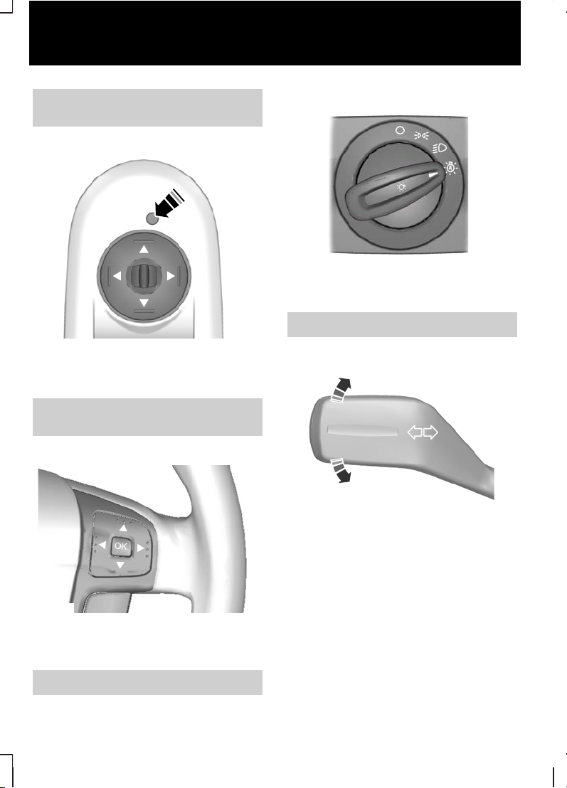
Information displays
E70499
Use the arrow buttons to navigate
through the menus and press OK to
make a selection.
See Informationdisplays (page 76).
Autolamps
E70719
The headlamps will come on and go off
automatically depending on the ambient
light.
See Lighting control (page 50).
Direction indicators
E70727
Note:
Tap the lever up or down to make
the direction indicators flash only three
times.
12
Quick start
Page 15
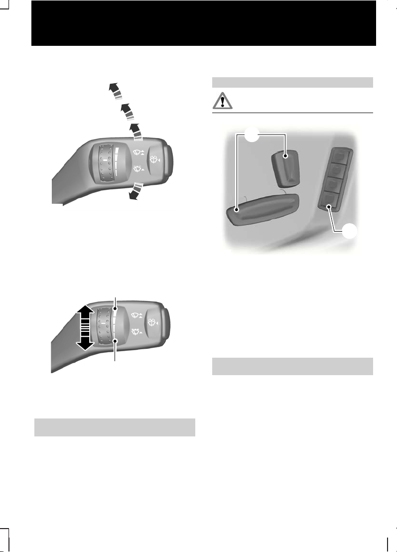
Autowipers
B
C
D
A
E70696
Single wipeA
AutowipersB
Normal wipeC
High speed wipeD
E70316
A
B
High sensitivityA
Low sensitivityB
See Autowipers (page 46).
Memory function
WARNING
Do not use the memory store
function when the vehicle is moving.
A
B
E86768
Seat adjustment controls.A
Memory pre-set buttons.B
1. Turn the ignition on.
2. Adjust the seat and exterior mirrors to
the desired position.
3. Press and hold the desired pre-set
button B until a single chime sounds
to confirm.
See Memory function (page 118).
13
Quick start
Page 16
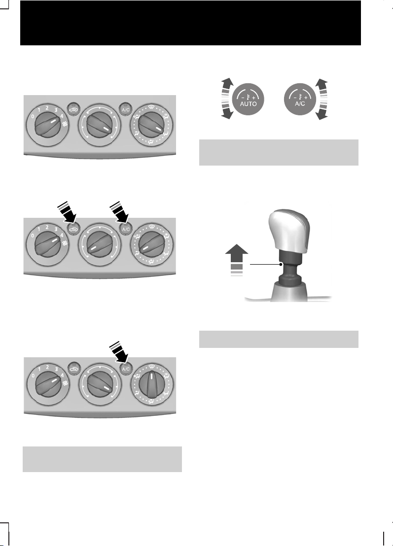
Manual climate control
Heating the interior quickly
E71377
Cooling the interior quickly
E71381
Defrosting and demisting the
windscreen
E71382
See Manual climate control (page
98).
Automatic climate control
E70304
See Automatic climate control
(page 100).
Manual transmission
Selecting reverse gear
E99067
On some vehicles it is necessary to raise
the collar whilst selecting reverse gear.
See Manualtransmission (page 132).
14
Quick start
Page 17
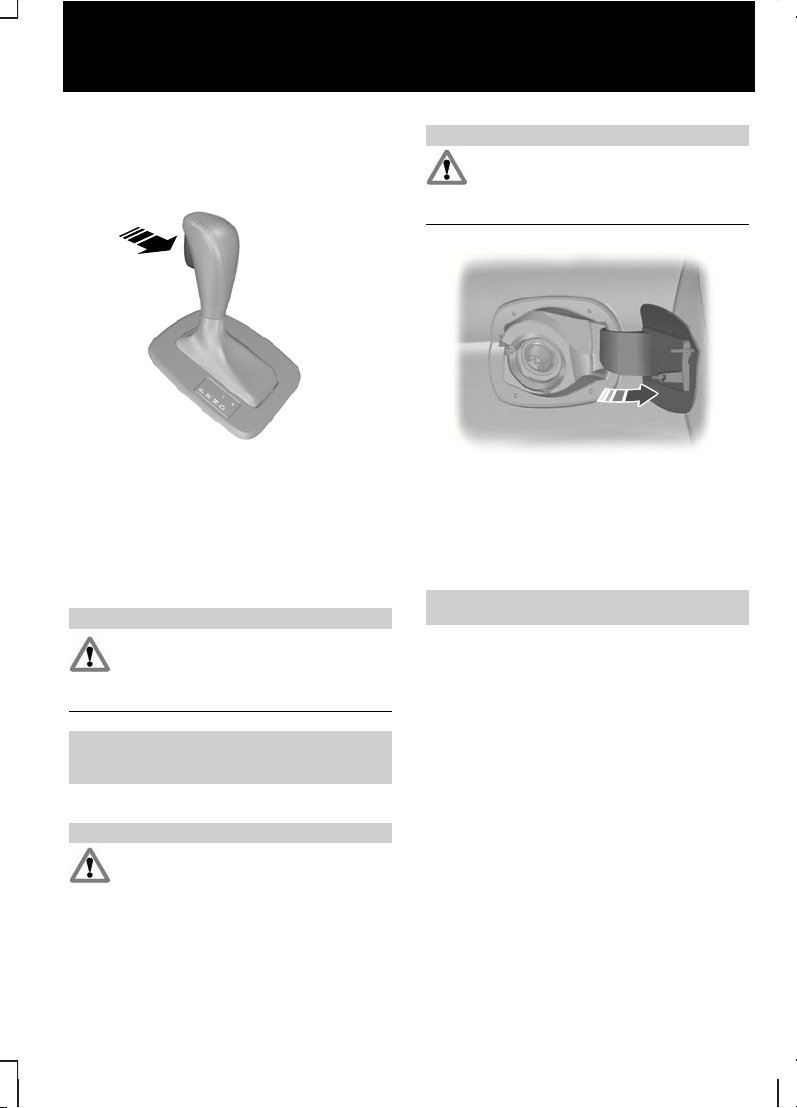
Automatic transmission
Selector lever positions
E80836
S
ParkP
ReverseR
NeutralN
DriveD
Manual shifting and sport modeS
WARNING
Apply the brakes before moving the
selector lever and keep them
applied until you are ready to move
off.
See Automatic transmission (page
132).
Fuel filler flap
WARNINGS
Take care when refuelling to avoid
spilling any residual fuel from the fuel
pipe nozzle.
WARNINGS
We recommend that you wait at
least 10 seconds before removing
the fuel pipe nozzle to allow any
residual fuel to drain into the fuel tank.
E86613
Press the flap to open it. Open the flap
fully until it engages.
When you insert the fuel pipe nozzle, a
spring loaded inhibitor will open if the
correct size nozzle is detected. This will
prevent filling up with the wrong fuel.
See Fuel filler flap (page 128).
15
Quick start
Page 18
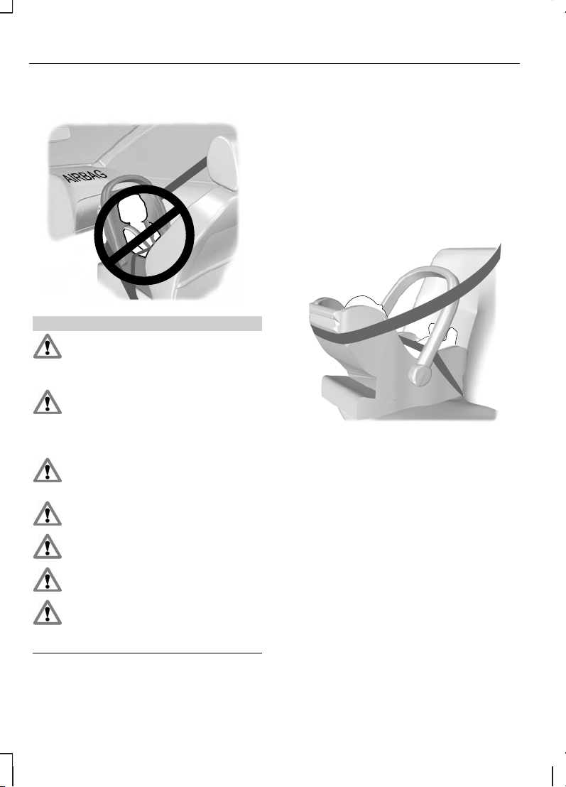
CHILD SEATS
E68916
WARNINGS
Secure children that are less than
150 centimetres tall or less than 12
years of age in a suitable, approved
child restraint, in the rear seat.
Original text according to ECE
R94.01: ExtremeHazard! Donot use
a rearward facing child restraint on
a seat protected by an air bag in front of
it!
Read and follow the manufacturer’s
instructions when you are fitting a
child restraint.
Do not modify child restraints in any
way.
Do not hold a child on your lap when
the vehicle is moving.
Do not leave unattended children in
your vehicle.
If your vehicle has been involved in
an accident, have the child restraints
checked by properly trained
technicians.
Note:
Mandatory use of child restraints
varies from country to country.
Only child restraints certified to
ECE-R44.03 (or later) have been tested
and approved for use in your vehicle. A
choice of these are available from your
Dealer.
Child restraints for different
mass groups
Use the correct child restraint as follows:
Baby safety seat
E68918
Secure children that weigh less than 13
kilograms in a rearward facing baby safety
seat (Group 0+) in the rear seat.
16
Child safety
Page 19
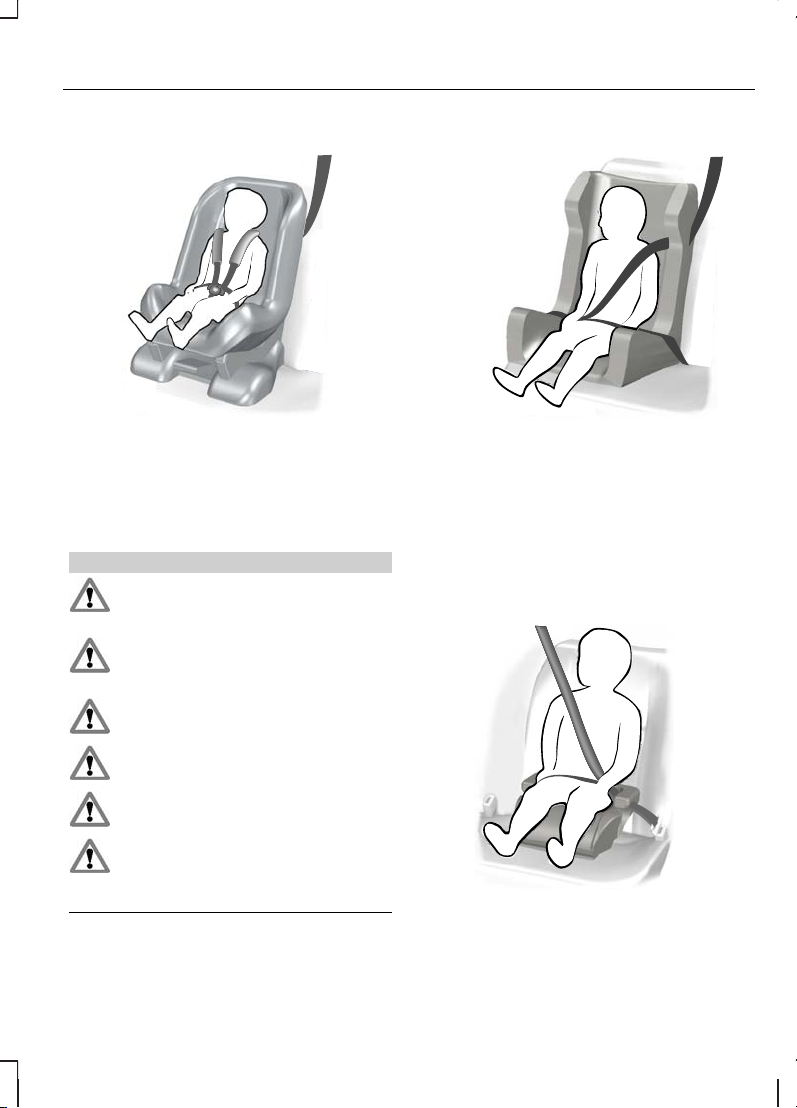
Child safety seat
E68920
Secure children that weigh between 13
and 18 kilograms in a child safety seat
(Group 1) in the rear seat.
BOOSTER CUSHIONS
WARNINGS
Do not install a booster seat or a
booster cushion with only the lap
strap of the seat belt.
Do not install a booster seat or a
booster cushion with a seat belt that
is slack or twisted.
Do not put the seat belt under your
child’s arm or behind its back.
Do not use pillows, books or towels
to boost your child’s height.
Make sure that your children sit in
an upright position.
Secure children that weigh more
than 15 kilogrammes but are less
than 150 centimetres tall in a
booster seat or a booster cushion.
Booster seat
E70710
We recommend that you use a booster
seat that combines a cushion with a
backrest instead of a booster cushion
only. The raised seating position will allow
you to position the shoulder strap of the
adult seat belt over the centre of your
child’s shoulder and the lap strap tightly
across its hips.
Booster cushion
E68924
17
Child safety
Page 20

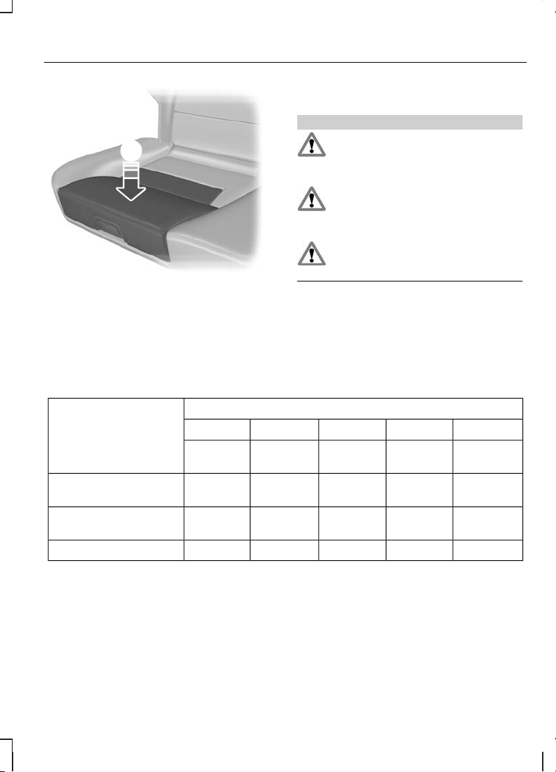
Integrated booster cushion
WARNINGS
Do not use the raised integrated
booster cushion together with a
child safety seat.
The integrated booster cushion can
be used for children that weigh
between 22 and 36 kilogrammes
(49 and 79 pounds).
CAUTION
Remove the rear seat head restraint
unless the child's head exceeds the
top of the backrest. See Head
restraints (page 112).
Unlocking
1
2
E94860
Note:
Make sure that the locking
mechanism is fully engaged.
3
E94861
The raised seating position will allow you
to position the shoulder strap of the adult
seat belt over the centre of your child’s
shoulder and the lap strap tightly across
its hips.
Locking
Note:
Make sure that there are no
obstructions in the linkage area before
locking the integrated booster cushion.
2
E94862
1
Note:
Make sure that the locking
mechanism is fully engaged.
18
Child safety
Page 21
E94870
3
CHILD SEAT POSITIONING
WARNINGS
When using a child restraint with a
support leg on a second row seat,
make sure the support leg rests
securely on the floor.
When using a forward facing child
seat on a second row seat, always
remove thehead restraint from that
seat.
When fitting a child seat using the
vehicle seat belts make sure the
belts are not slack.
Note:
When using a child restraint on a
front seat, it may prove difficult to tighten
the lap section of the seat belt without
slack remaining. If this is the case, adjust
the seatback to the fully upright position
and raise the height of the seat. See
Seats (page 109).
Mass group categoriesSeating positions
IIIIII0+0
22 - 36 kg15 - 25 kg9 - 18 kgUp to 13
kg
Up to 10
kg
UF¹UF¹UF¹XXFront passenger seat
with airbag ON
U¹U¹U¹U¹U¹Front passenger seat
with airbag OFF
UUUUURear seats
X Not suitable for children in this mass group.
U Suitable for universal category child restraints approved for use in this mass group.
U¹ Suitable for universal category child restraints approved for use in this mass group.
However, we recommend that you secure children in a government approved child
restraint, in the rear seat.
19
Child safety
Page 22

UF¹ Suitable for universal category forward facing child restraints approved for use in
this mass group. However, we recommend that you secure children in a government
approved child restraint, in the rear seat.
ISOFIX child restraints
Mass group categoriesSeating positions
IIIIII0+0
22 - 36 kg15 - 25 kg9 - 18 kgUp to 13
kg
Up to 10
kg
XXIL, IUF**ILILRear seat ISOFIX
restraints
XXA, B, B1, C,
D
C, D, EERear seat ISOFIX
classes*
X Not suitable for children in this mass group.
IUF Suitable for universal category ISOFIX child restraints approved for use in this mass
group.
IL Suitable for the following ISOFIX child restraints: Roemer Duo ISOFIX(group 1), Roemer
Babysafe ISOFIX (group 0+). In addition, any semi-universal ISOFIX child restraint may
be used if indicated in the child seat manufacturers vehicle list.
* As defined by ECE-R16.
Note:
** When you are purchasing an ISOFIX restraint, make sure that you know the
correct mass group and ISOFIX size class for the intended seating locations.
Note:
** Make sure that the top tether mechanism does not interfere with the luggage
cover.
20
Child safety
Page 23
ISOFIX ANCHOR POINTS
WARNING
Use an anti-rotation device when
using the ISOFIX system. We
recommend the use of a top tether
or support leg.
Your vehicle is fitted with ISOFIX anchor
points that accommodate universally
approved ISOFIX child restraints.
The ISOFIX system comprises two rigid
attachment arms on the child restraint
that attach to anchor points on the
outboard rear seats, where the cushion
and backrest meet. Tether anchor points
are fitted behind the outboard rear seats
for child restraints with a top tether.
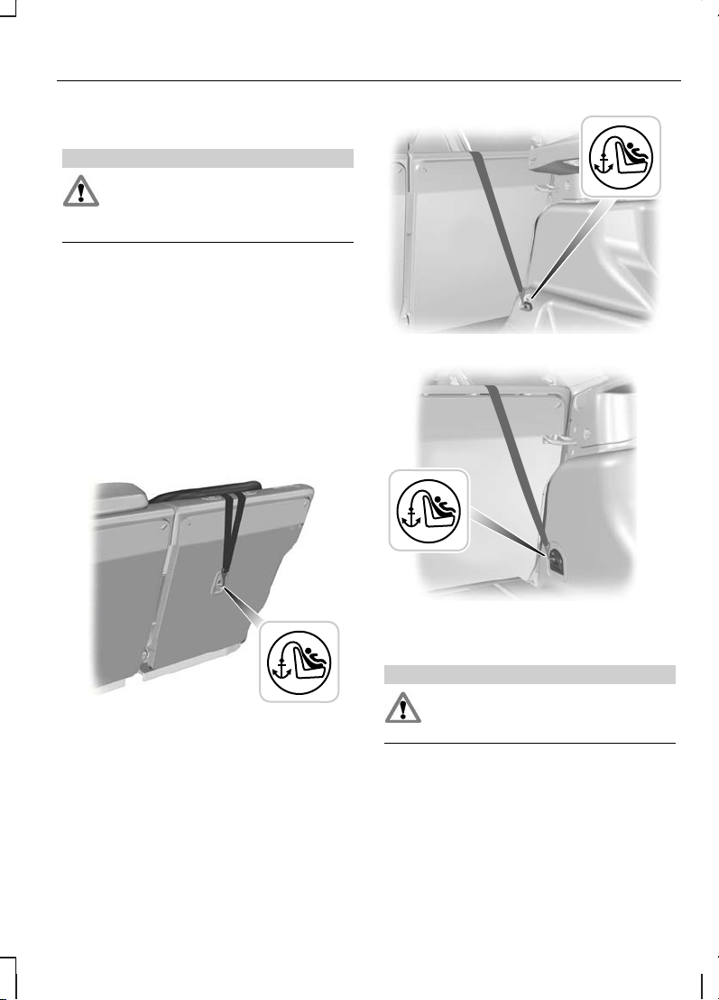
Top tether anchor points
E87146
E93616
E93514
Attaching a child seat with top
tethers
WARNING
Do not attach a tether strap to
anything other than the correct
tether anchor point.
Note:
Where applicable, remove the
luggage cover to ease installation. See
Luggage covers (page 155).
Note:
On 4-door vehicles, make sure the
tether strap tightening mechanism
remains accessible when the seatback is
fully engaged.
21
Child safety
Page 24
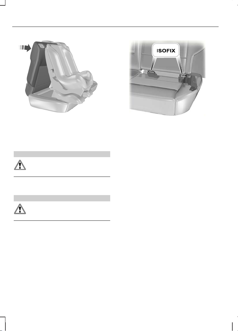
E87591
1. Place the child seat on the back seat
cushion and fold the relevant seatback
forwards. See Rear seats (page 112).
2. Remove the head restraint. See
Head restraints (page 112).
WARNING
Make sure the top tether strap is not
slack or twisted and is properly
located on the anchor point.
3. Route the tether strap to the anchor
point.
WARNING
Make sure that the seatback is
secure and fully engaged in the
catch.
4. Push the seatback to the upright
position.
E87145
5. Push the child seat back firmly to
engage the ISOFIX lower anchor
points.
6. Tightenthe tetherstrap inline with the
child seat manufacturer's instructions.
22
Child safety
Page 25
CHILD SAFETY LOCKS
WARNING
You cannot open the doors from
inside if you have put the childsafety
locks on.
E73697
A
B
LockA
UnlockB
23
Child safety
Page 26
PRINCIPLE OF OPERATION
Airbags
WARNINGS
Do not modify the front of your
vehicle in any way. This could
adversely affect deployment of the
airbags.
Original text according to ECE
R94.01: ExtremeHazard! Donot use
a rearward facing child restraint on
a seat protected by an airbag in front of
it!
Wear a seat beltand keep sufficient
distance between yourself and the
steering wheel. Only when you use
the seat belt properly, can it hold you in a
position that allows the airbag to achieve
its optimum effect. See Sitting in the
correct position (page 109).
Have repairs to the steering wheel,
steering column,seats, airbags and
seat belts carried out by a properly
trained technician.
Keep the areas in front of the
airbags free from obstruction. Do
not affix anything to or over the
airbag covers.
Do not poke sharp objects into
areas where airbags are fitted. This
could damage and adversely affect
deployment of the airbags.
Use seat covers designed for seats
with side airbags. Have these fitted
by a properly trained technician.
Note:
You will hear a loud bang and see
a cloudof harmless powdery residue if an
airbag deploys. This is normal.
Note:
Only wipe airbag covers with a
damp cloth.
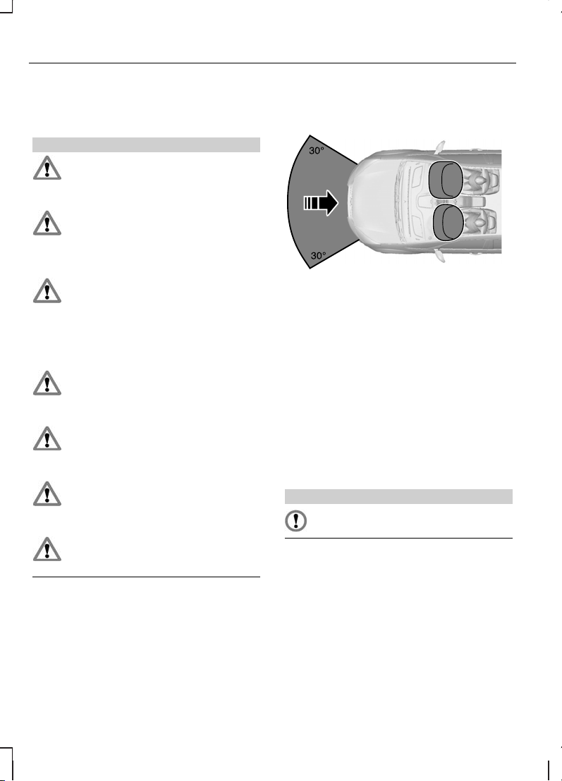
Driver and front passenger airbags
E74302
The driver and front passenger airbags
will deploy during significant frontal
collisions or collisions that are up to 30
degrees from the left or the right. The
airbags will inflate within a few
thousandths of a second and deflate on
contact with the occupants, thus
cushioning forward body movement.
During minor frontal collisions, overturns,
rear collisions and side collisions, the driver
and front passenger airbags will not
deploy.
Driver knee airbag
CAUTION
Do not attempt to open the driver
knee airbag cover.
The driver knee airbag will deploy during
frontal collisions or collisions that are up
to 30 degrees from the left or the right.
The airbag will inflate within a few
thousandths of a second and deflate on
contact with the occupants, thus
providing a cushion between the driver’s
knees and the steering column. During
overturns, rear collisions and side
collisions, the knee airbag will not deploy.
24
Occupant protection
Page 27
For item location: See Quick start (page
8).
Note:
The knee airbag has a lower
deployment threshold than the front
airbags. During a minor collision, it is
possible that only the knee airbag
deploys.
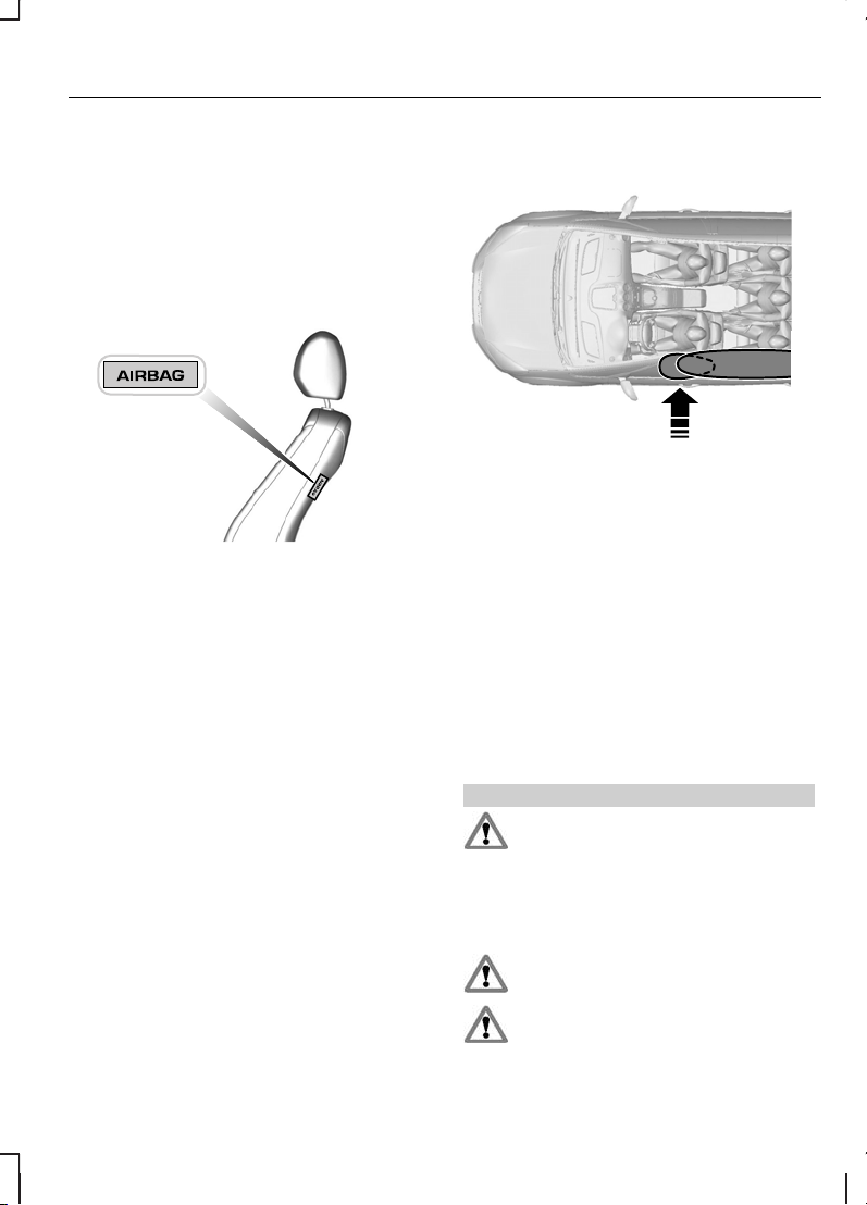
Side airbags
E72658
Side airbags are fitted inside the seatback
of the front seats. A label indicates that
side airbags are fitted to your vehicle.
The side airbags will deploy during
significant lateral collisions. The airbags
will inflate within a few thousandths of a
second and deflate on contact with the
occupants, thus providing protection for
the chest and shoulder areas. During
minor lateral collisions, overturns, front
collisions and rear collisions, the side
airbags will not deploy.
Curtain airbags
E75004
Curtain airbags are fitted inside the trim
panels over the front and rear side
windows. Moulded badges in the B-pillar
trim panels indicate that curtain airbags
are fitted to your vehicle.
The curtain airbags will deploy during
significant lateral collisions. The airbag will
inflate within a few thousandths of a
second and deflate on contact with the
occupants, thus providing protection for
the head. During minor lateral collisions,
front collisions, rear collisions, or overturns
the curtain airbags will not deploy.
Seat belts
WARNINGS
Wear a seat beltand keep sufficient
distance between yourself and the
steering wheel. Only when you use
the seat belt properly, can it hold you in a
position to achieve its optimum effect.
See Sitting in the correct position
(page 109).
Never use a seat belt for more than
one person.
Use the correct buckle for each seat
belt.
25
Occupant protection
Page 28
WARNINGS
Do not use a seat belt that is slack
or twisted.
Do notwear thick clothing. The seat
belt must fit tightly around your body
to achieve its optimum effect.
Position the shoulder strap of the
seat belt over the centre of your
shoulder and position the lap strap
tightly across your hips.
The driver and front passenger seat belt
retractors are fitted with a seat belt
pretensioner. Seat belt pretensioners
have a lower deployment threshold than
the airbags. During minor collisions, it is
possible that only the seat belt
pretensioners will deploy.
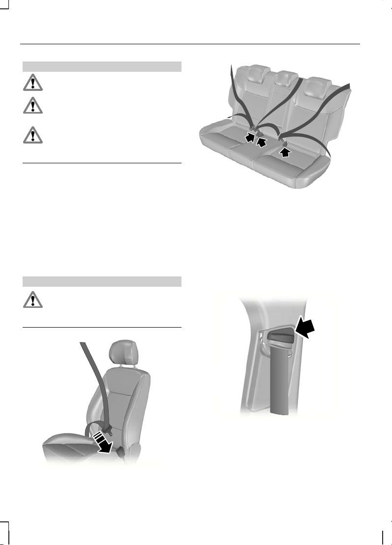
FASTENING THE SEAT BELTS
WARNING
Insert the tongue into the buckle
until you hear a distinct click. You
have not fastened the seat belt
properly if you do not hear a click.
E74124
E85817
Pull the belt out steadily. It may lock if you
pull it sharply or if the vehicle is ona slope.
Press the red button on the buckle to
release the belt. Let it retract completely
and smoothly.
SEAT BELT HEIGHT ADJUSTMENT
E87511
Note:
Lifting the slider slightly while
pressing the locking button makes it
easier to release the locking mechanism.
To raise or lower, press the locking button
on the adjuster and move as necessary.
26
Occupant protection
Page 29
SEAT BELT REMINDER
WARNING
Do not sit on top of a fastened seat
belt to prevent the seat belt
reminder from coming on. The
occupant protection system will only
provide optimum protection when you
use the seat belt properly.
The seat belt reminder warning
lamp illuminates and an audible
warning will sound if you or your
front seat passenger have not fastened
your seat belts and the vehicle exceeds
10 km/h (6 mph). It will also illuminate if
your seat belts are unfastened when the
vehicle is moving. The audible warning will
go off after five minutes but the seat belt
reminder warning lamp will remain on until
you fasten your seat belts.
Deactivating the seat belt
reminder
See your dealer.
USING SEAT BELTS DURING PREGNANCY
E68587
WARNING
Position the seat belt correctly for
your safety and that of your unborn
child. Do not use only the lap strap
or the shoulder strap.
Position the lap strap comfortably across
your hips and low beneath your pregnant
abdomen. Position the shoulder strap
between your breasts, above and to the
side of your pregnant abdomen.
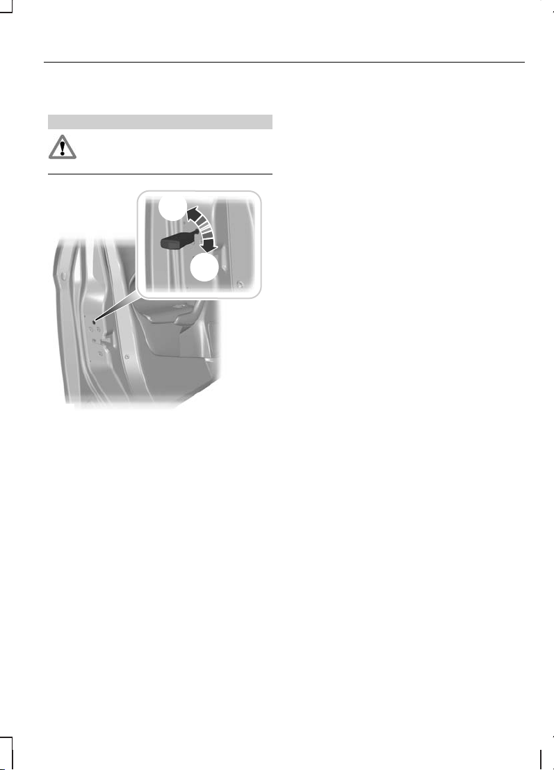
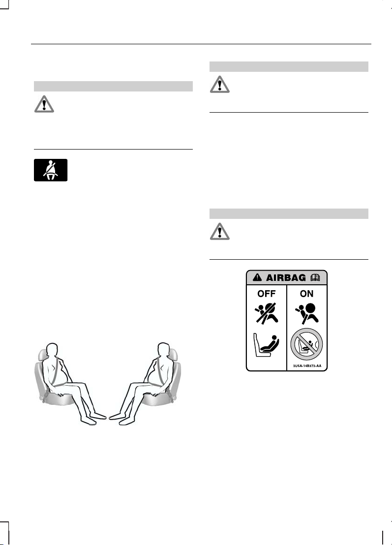
DISABLING THE PASSENGER AIRBAG
WARNING
Make sure that the passenger
airbag is disabled when using a
rearward facing child restraint on the
front passenger seat.
E71313
27
Occupant protection
Page 30
Fitting the passenger airbag
deactivation switch
WARNING
If you need to fit a child restraint on
a seat protected by an operational
airbag in front of it, have a
passenger airbag deactivation switch
fitted. Ask your dealer for further
information.
Note:
The key switch is located in the
glove compartment with an airbag
deactivation lamp in the instrument panel.
If the airbag warning lamp illuminates or
flashes when you are driving, this indicates
a malfunction. See Warninglamps and
indicators (page 73). Remove the child
restraint and have the system checked
immediately.
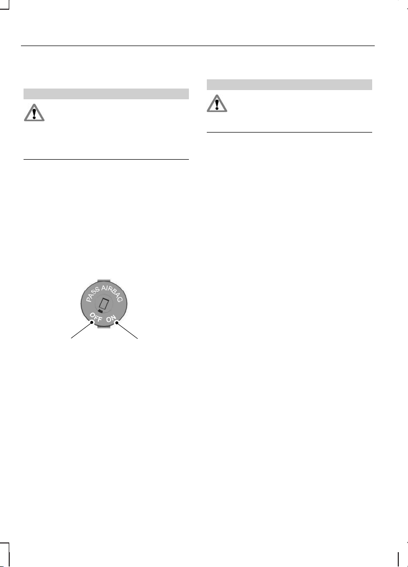
Disabling the passenger airbag
A B
E71312
DisabledA
EnabledB
Turn the switch to position A.
When you switch the ignition on, check
that the passenger airbag deactivation
warning lamp illuminates.
Enabling the passenger airbag
WARNING
Make sure that the passenger
airbag is enabled when you are not
using a child restraint on the front
passenger seat.
Turn the switch to position B.
28
Occupant protection
Page 31

USING THE KEY
Remote control with flip key
blade
E74382
GENERALINFORMATIONON RADIO FREQUENCIES
CAUTION
The radio frequency used by your
remote control can also be used by
other short distance radio
transmissions (e.g. amateur radios,
medical equipment,wireless headphones,
remote controls and alarm systems). If
the frequencies are jammed, you will not
be able to use your remote control. You
can lock and unlock the doors with the
key.
Note:
You could unlock the doors if you
press the buttons on the remote control
unintentionally.
The operating range between your
remote control and your vehicle varies
depending on the environment.
PROGRAMMING THE REMOTE CONTROL
You can programme a maximum of eight
remote controls to use with your vehicle
(including any supplied with your vehicle).
Programming a new remote
control
1. Insert the key in the ignition.
2.
Cycle the key from position 0 to II and
then back to 0 four times in quick
succession (about once a second).
3. Remove the key from the ignition and
press any button on the remote
control.
4. Reinsert the key and turn to position
II then 0. Remove the key and test
the remote control to confirm
programming has been successful.
Reprogramming the unlocking
function
Note:
When you press the unlock button
either all the doors are unlocked or only
the driver’s door isunlocked. Pressing the
unlock buttonagain unlocksall thedoors.
Press and hold the unlock and lock
buttons onthe remotekey simultaneously
for at least four seconds with the ignition
off. The direction indicators will flash twice
to confirm the change.
Toreturn to the original unlocking function,
repeat the process.
29
Keys and remote controls
Page 32

CHANGING THE REMOTE CONTROL BATTERY
Remote control with a folding
key blade
E74383
1
1. Insert a screwdriver as far as possible
into the slot on the side of the remote
control, push it towards the key blade
and remove the key blade.
E74384
2
2. Twist the screwdriver in the position
shown to start separating the two
halves of the remote control.
3
E74385
3. Twist the screwdriver in the position
shown to separate the two halves of
the remote control.
CAUTION
Do not touch the battery contacts or
the printed circuit board with the
screwdriver.
4. Carefully prise out the battery with the
screwdriver.
5. Install a new battery (3V CR 2032) with
the + facing downwards.
6. Assemble the two halves of the
remote control.
7. Install the key blade.
30
Keys and remote controls
Page 33

Remote control without a
folding key blade
Type 1
E74386
1. Insert a screwdriver into the recess on
the back of the key and remove the
key blade.
2. Release the retaining clips with the
screwdriver and separate the two
halves of the remote control.
CAUTION
Do not touch the battery contacts or
the printed circuit board with the
screwdriver.
3. Carefully prise out the battery with the
screwdriver.
4. Install a new battery (3V CR 2032) with
the + facing upwards.
5. Assemble the two halves of the
remote control.
6. Install the key blade.
Type 2
1
2
E78284
1. Slide the release slider in the direction
of the arrow.
2. Remove the key blade.
E105064
3
3. Twist the screwdriver in the position
shown to separate the two halves of
the remote control.
CAUTION
Do not touch the battery contacts or
the printed circuit board with the
screwdriver.
31
Keys and remote controls
Page 34

4. Carefully prise out the battery with the
screwdriver.
5. Install a new battery (3V CR 2032) with
the + facing downwards.
6. Assemble the two halves of the
remote control.
7. Install the key blade.
Type 3
1
2
1
E87964
1. Carefully remove the cover.
2. Remove the key blade.
3
E105362
3. Twist the screwdriver in the position
shown to separate the two halves of
the remote control.
CAUTION
Do not touch the battery contacts or
the printed circuit board with the
screwdriver.
4. Carefully prise out the battery with the
screwdriver.
5. Install a new battery (3V CR 2032) with
the + facing downwards.
6. Assemble the two halves of the
remote control.
7. Install the key blade.
32
Keys and remote controls
Page 35

LOCKING AND UNLOCKING
Central locking
You can only centrally lock the doors if
they are all closed.
Note:
The driver’s door can be unlocked
with the key. This needs to be used if the
remote control or keyless entry is not
functioning.
Note:
Central locking also locks and
unlocks the fuel filler flap.
Double locking
WARNING
Do not activate double locking when
persons or animals are inside the
vehicle. You will not be able to
unlock the doors from the inside if you
have double locked them.
E71961
Double locking is a theft protection feature
that prevents someone from opening the
doors from the inside. You can only
double lock the doors if they areall closed.
Locking and unlocking
confirmation
When you unlock the doors, the direction
indicators will flash once.
When you lock the doors, the direction
indicators will flash twice.
Note:
If your vehicle has double locking,
the direction indicators will only flash twice
once you have activated double locking.
Locking and unlocking the
doors with the key
B
E71962
A
B
A
UnlockA
LockB
Double locking the doors with
the key
Turn the key to the lock position twice
within three seconds to double lock the
doors.
33
Locks
Page 36

Locking and unlocking the
doors and the luggage
compartment lid with the
remote control
E87379
A B C
UnlockA
LockB
Luggage compartment lid
unlock
C
Locking the doors and the luggage
compartment lid with the remote
control
Press button B once.
Double locking the doors and the
luggage compartment lid with the
remote control
Press button B twice within three
seconds.
Locking and unlocking the
doors from inside
Driver's door
A
B
Lock all doorsA
Unlock all doorsB
Front and rear passenger doors
To lock the front and rear passenger
doors individually, press the button and
close the door when leaving the vehicle.
34
Locks
Page 37

Luggage compartment lid
Opening the luggage compartment
lid with the remote control
Press button C on the remote control
twice within three seconds.
Closing the luggage compartment
lid
4-door
E89131
5-door
E89132
Estate
E89133
A recessedgrip is incorporated inside the
luggage compartment lid to facilitate
closing.
Automatic relocking
The doors will relock automatically if you
do not open a door within 45 seconds of
unlocking the doors with the remote
control. The door locks and the alarm will
return to their previous state.
Reprogramming the unlocking
function
The unlocking function may be
reprogrammed so that only the driver’s
door is unlocked. See Programming
the remote control (page 29).
GLOBAL OPENING AND CLOSING
You can also operate the electric
windows with the ignition off via theglobal
opening and global closing function.
Note:
Global closing will only operate if
you have set the memory correctly for
each window. See Electric windows
(page 66).
35
Locks
Page 38

Global opening
E71955
To open all the windows, press and hold
the unlock button for at least three
seconds. Press either the lock or the
unlock button again to stop the opening
function.
Global closing
Vehicles without the key free
system
WARNING
Take care when using global
closing. In an emergency, press a
button immediately to stop.
E71956
To close all the windows, press and hold
the lock button for at least three
seconds. Press any button again to stop
the closing function. The anti-trap function
is also active during global closing.
Vehicles with the key free system
E87384
WARNING
Take care when using global
closing. In an emergency, press the
button on the driver’s door handle
to stop.
Note:
Global closing can be activated
using the button on the driver’s door
handle. Global opening and closing can
also be activated using the buttons on the
passive key.
36
Locks
Page 39

To close all the windows, press and hold
the button on the driver’s door handle for
at least two seconds. The anti-trap
function is also active during global
closing.
KEYLESS ENTRY
General information
WARNING
The keyless entry system may not
function if the key is close to metal
objects or electronic devices such
as mobile phones.
Note:
If the door handles are pulled
repeatedly during a short period of time
without the presence of a valid passive
key, the system will become inoperable
for 30 seconds.
The passiveentry system will not function
if:
•
The passive key frequencies are
jammed.
•
The passive key battery is flat.
Note:
If the passive entry system does
not function, you will need to use the key
blade to lock and unlock your vehicle.
The keyless system allows the driver to
operate the vehicle without the use of a
key or remote control.
E78276
Passive locking and unlocking requires a
valid passive key to be located within one
of the three external detection ranges.
These are located approximately one and
a half metres from the driver and front
passenger door handles and the luggage
compartment lid.
Passive key
The vehicle can be locked and unlocked
with thepassive key. The passive key can
also be used as a remote control. See
Locking and unlocking (page 33).
Locking the vehicle
E87384
E87435
37
Locks
Page 40

WARNING
The vehicle does not lock itself
automatically. If no locking button is
pressed, the vehicle will remain
unlocked.
Note:
If locking from the luggage
compartment lid, the passive key must
be within the luggage compartment lid
detection range.
Locking buttons are located on each of
the front doors and the luggage
compartment lid.
To activate central locking and arm the
alarm:
•
Press a locking button once.
To activate double locking, to arm the
alarm and the interior sensors:
•
Press a locking button twice within
three seconds.
Note:
Once activated, the vehicle will
remain locked for approximately three
seconds. This is to allow you to pull a door
handle and check if the vehicle is locked.
When the delay period is over, the doors
can be opened again, provided the
passive key is within the respective
detection range.
Luggage compartment lid
Note:
The luggage compartment lid
cannot be closed and will pop back up if
the passive key is located inside the
luggage compartment.
Note:
If a second valid passive key is
located within the luggage compartment
lid detection range, the luggage
compartment lid can be closed.
Unlocking the vehicle
Note:
If the vehicle remains locked for
longer than five days, the key free system
will enter an energy-saving mode. This is
to reduce the discharge of the vehicle
battery. When the vehicle is unlocked
while in this mode, the reaction time of
the system may be a little longer than
normal. Unlocking the vehicle once will
deactivate the energy-saving mode.
E78278
Pull one of the door handles or the
luggage compartment lid handle.
Note:
A valid passive key must be
located within the detection range of that
door.
One long flash of the direction indicators
confirms that all the doors, the luggage
compartment lid and the fuel filler flap
have been unlocked and that the alarm
has been disarmed.
Unlocking only the driver's door
If the unlocking function is reprogrammed
so that only the driver’s door is unlocked
( See Keys and remote controls
(page 29). ), note the following:
38
Locks
Page 41

If the driver’s door is the first door which
is opened, the other doors and the
luggage compartment lid will remain
locked. All the other doors can be
unlocked from inside the vehicle by
pressing the unlock button next to the
driver’s door handle. Doors can be
unlocked individually by pulling the interior
door handles on those doors.
If the front passenger door or one of the
rear doors is the first door which is
opened, all the doors and the luggage
compartment lid will be unlocked.
Disabled keys
Any keys left inside the vehicle interior
when it is locked will be disabled.
A disabledkey cannot be used toturn the
ignition on or start the engine.
In order to use these passive keys again,
they have to be enabled.
To enable all your passive keys, unlock
the vehicle using a passive key or the
remote control unlocking function.
All passive keys will then be enabled if the
ignition is turned on or the vehicle is
started using a valid key.
Locking and unlocking the
doors with the key blade
Type 1
1
2
E78284
1. Slide the release slider in the direction
of the arrow and pull out the key blade
with your thumb.
2. Remove the key blade and insert it
into the lock.
Type 2
1
2
1
E87964
1. Carefully remove the cover.
2. Remove the key blade and insert it
into the lock.
39
Locks
Page 42

PRINCIPLE OF OPERATION
The engine immobiliser is a theft
protection systemthat preventssomeone
from starting the engine with an
incorrectly coded key.
CODED KEYS
Note:
Do not shield your keys with metal
objects. This may prevent the receiver
from recognising your key as a valid one.
Note:
Have all of your remaining keys
erased and recoded if you lose a key. Ask
your dealer for further information. Have
replacement keysrecoded together with
your existing keys.
If you lose a key, you can obtain a
replacement from your Ford Dealer. If
possible, provide them with the key
number from the tag provided with the
original keys. You can also obtain
additional keys from your Ford Dealer.
ARMING THE ENGINE IMMOBILISER
The engine immobiliser is armed
automatically a short time after you have
switched the ignition off.
DISARMING THE ENGINE IMMOBILISER
The engine immobiliser is disarmed
automatically when you switch the ignition
on with a correctly coded key.
If the message Immobiliser active
appears in the information display, your
key has not been recognised. Remove
the key and try again.
If you are unable to start the engine with
a correctly coded key, this indicates a
malfunction. Themessage Immobiliser
active will appear in the information
display when you switch on the ignition.
Have the immobiliser checked
immediately.
40
Engine immobiliser
Page 43

PRINCIPLE OF OPERATION
Alarm system
Your vehicle may be equipped with one
of the following alarm systems:
•
Perimeter alarm.
•
Perimeter alarm with interior sensors.
•
Category one alarm with interior
sensors andbattery back-upsounder.
•
Category one alarm with interior
sensors, batteryback-up sounderand
tilt sensors.
Perimeter alarm
The perimeter alarm is a deterrent against
unauthorised access to your vehicle
through the doors and the bonnet. It also
protects the audio unit.
Interior sensors
E71401
WARNING
The sensors in the interior lamp unit
must not be covered up. Do not
activate the alarm with full guard if
any persons, animals or other moving
objects are inside the vehicle.
The sensors act as a deterrent against
unauthorised intrusion by sensing any
movement within the vehicle.
Battery back-up sounder
The battery back-up sounder is an extra
alarm system which will sound a siren
when the alarm is triggered. It is armed
directly when you lock the vehicle. The
sounder has its own battery and will
sound an alarm siren even if someone
disconnects the vehicle battery or the
battery back-up sounder itself.
Tilt sensors
The tilt sensors detect if someone
attempts to steal a wheel or tow the
vehicle away by sensing changes in the
inclination of the vehicle.
Note:
When travelling on a ferry with the
alarm armed, deactivate the tilt sensors
by selecting reduced guard. This will
prevent the alarm from being triggered
by the movement.
Triggering the alarm
Once armed, the alarm is triggered in any
of the following ways:
•
If someone opens a door, the tailgate
or the bonnet without a valid key or
remote control.
•
If someone removes the audio or
navigation system.
•
If the ignition is turned to position I, II
or III without a valid key.
•
If the interior sensors detect
movement within the vehicle.
•
On vehicles with a battery back-up
sounder, if someone disconnects the
vehicle batteryor the battery back-up
sounder itself.
•
If the tilt sensors detect a change in
the inclination of the vehicle.
If the alarm is triggered, the alarm horn will
sound for 30 seconds and the hazard
warning flasher will flash for five minutes.
41
Alarm
Page 44

Any further attempts to perform one of
the above will trigger the alarm again.
Full and reduced guard
Full guard
Full guard is the standard setting.
In full guard, the interior and tilt sensors
are activated when you arm the alarm.
Note:
This may result in false alarms if
animals or moving objects are inside the
vehicle or, on vehicles with tilt sensors,
when travelling on a ferry.
Reduced guard
In reduced guard, the interior and tilt
sensors are deactivated when you arm
the alarm.
Note:
You can set the alarm to reduced
guard for the current ignition cycle only.
The next time you switch on the ignition,
the alarm will be reset to full guard.
Ask on Exit
You can set the information display to ask
you each time which level of guard you
wish to set.
If you select Ask on Exit, the message
Reduced guard? appears in the
instrument cluster display each time you
switch the ignition off.
If you wish to arm the alarm with reduced
guard, press the OK button when this
message appears.
If you wish to arm the alarmwith full guard,
leave the vehicle without pressing the OK
button.
Selecting full or reduced guard
Note:
Selecting Reduced does not set
the alarmpermanently to reduced guard.
It sets it to reduced guard only for the
current ignition cycle. If you regularly set
the alarm to reduced guard, select Ask
on Exit.
E70499
E74509
Full Guard
Alarm
Reduced
Ask on Exit
1. Press the right arrow button on the
steering wheel to enter the main
menu.
2.
Highlight Setup with theup anddown
arrow buttons and press the right
arrow button.
3.
Highlight Alarm and press the right
arrow button.
42
Alarm
Page 45

4.
Highlight Reduced or Full guard. If
you prefer to be asked each time you
switch off the ignition, select Ask on
Exit.
5.
Press the OK button to confirm the
selection.
6. Press the left arrow button to exit the
menu. To return to the trip computer
display directly, hold the left arrow
button pressed.
Information messages
See Informationmessages (page 89).
ARMING THE ALARM
To arm the alarm, lock the vehicle. See
Locks (page 33).
DISARMING THE ALARM
Vehicles without keyless entry
Perimeter alarm
Disarm and silence the alarm by unlocking
the doors with the key and switching the
ignition on with a correctly coded key, or
unlocking the doors or the luggage
compartment lid with the remote control.
Category one alarm
Disarm and silence the alarm by unlocking
the doors with the key and switching the
ignition on with a correctly coded key
within 12seconds, orunlocking the doors
or the luggage compartment lid with the
remote control.
Vehicles with keyless entry
Note:
A valid passive key must be
located within the detection range of that
door for keyless entry. See Keyless
entry (page 37).
Perimeter alarm
Disarm and silence the alarm by unlocking
the doors and switching the ignition on,
or unlocking the doors or the luggage
compartment lid with the remote control.
Category one alarm
Disarm and silence the alarm by unlocking
the doors and switching the ignition on
within 12seconds, orunlocking the doors
or the luggage compartment lid with the
remote control.
43
Alarm
Page 46

ADJUSTING THE STEERING WHEEL
WARNING
Never adjust the steering wheel
when the vehicle is moving.
Note:
Make sure that you are sitting in
the correct position. See Sitting in the
correct position (page 109).
1
2
2
E95178
3
E95179
WARNING
Make sure that you fully engage the
locking lever when returning it to its
original position.
AUDIO CONTROL
E72288
A
C
B
D
E
Volume upA
Seek upB
Volume downC
Seek downD
ModeE
Mode
Press and hold the mode button to
select the audio source.
Press the mode button to:
•
tune the radio to the next preset
station
•
play the next CD
•
play the other side of a cassette tape
•
accept an incoming telephone call.
•
end a telephone call.
44
Steering wheel
Page 47

Seek
Press a seek button to:
•
tune the radio to the next station up
or down the frequency band
•
play the next or the previous CD track
•
fast forward or rewind the cassette
tape.
Press and hold a seek button to:
•
tune the radio up or down the
frequency band
•
seek through a CD track.
45
Steering wheel
Page 48

WINDSCREEN WIPERS
B
C
D
A
E70696
Single wipeA
Intermittent wipeB
Normal wipeC
High speed wipeD
Intermittent wipe
E70315
B
A
C
Short wipe intervalA
Intermittent wipeB
Long wipe intervalC
AUTOWIPERS
CAUTIONS
Do not switch autowipers on in dry
weather conditions. The rain sensor
is very sensitive and the wipers may
operate if dirt, mist or flies hit the
windscreen.
Replace the wiper blades as soon as
they begin to leave bands of water
and smears. If you do not replace
them, the rain sensor will continue to
detect water on the windscreen and the
wipers will operate, even though the
majority of the windscreen is dry.
Fully defrost the windscreen in icy
conditions before you switch
autowipers on.
Switch autowipers off before you
enter a car wash.
E70315
B
A
C
High sensitivityA
OnB
Low sensitivityC
46
Wipers and washers
Page 49

If you switch autowipers on, the wipers
will not cycle until water is detected on
the windscreen. The rain sensor will then
continuously measure the amount of
water on the windscreen and adjust the
speed of the wipers automatically.
Adjust the sensitivity of the rain sensor
using the rotary control. With low
sensitivity, the wipers will operate when
the sensor detects a lot of water on the
windscreen. With high sensitivity, the
wipers will operate if the sensor detects
a small amount of water on the
windscreen.
WINDSCREEN WASHERS
WARNING
Do not operate the windscreen
washers for more than 10 seconds
or when the reservoir is empty.
Note:
The washer jets are heated when
the ignition is on.
E70776
REAR WINDOW WIPER AND WASHERS
Intermittent wipe
E70777
Reverse gear wipe
The rear window wiper will operate
automatically when you select reverse
gear if the wiper lever is in position B, C
or D.
Washer
WARNING
Do not operate the rear window
washer for more than 10 seconds
or when the reservoir is empty.
E70777
Pull the lever fully towards the steering
wheel and hold it to operate the washer.
47
Wipers and washers
Page 50

HEADLAMP WASHERS
The headlamp washers will operate with
the windscreen washers when the
headlamps are on.
Note:
To stop the washer fluid reservoir
emptying quickly, the headlamp washers
will not operate every time that you use
the windscreen washers.
CHECKING THE WIPER BLADES
E66644
Run the tip of your fingers over the edge
of the blade to check for roughness.
Clean the wiper blade lips with water
applied with a soft sponge.
CHANGING THE WIPER BLADES
Windscreen wiper blades
CAUTIONS
Set the windscreen wipers in the
service position to change the wiper
blades.
CAUTIONS
You can use the service position in
winter to provide easier access to
the wiper blades for freeing them
from snow and ice. The windscreen
wipers will return to their normal position
as soon as you switch on the ignition so
make sure that you fully defrost the
windscreen before you switch on the
ignition.
Service position
E85833
A
E75188
Switch off the ignition and move the wiper
lever to position A within three seconds.
Release the lever when the windscreen
wipers have moved to the service
position.
48
Wipers and washers
Page 51

Changing the windscreen wiper
blades
Set the windscreen wipers in the service
position and lift the wiper arms.
E72899
1
2
1. Press the locking button.
2. Remove the wiper blade.
Note:
Make sure that the wiper blade
locks into place.
3. Install in the reverse order.
Rear window wiper blades
Changing the rear window wiper
blades - Estate
1. Lift the wiper arm.
2
3
4
E86456
2. Position the wiper blade at right angles
to the wiper arm.
3. Disengage the wiper blade from the
wiper arm.
4. Remove the wiper blade.
Note:
Make sure that the wiper blade
locks into place.
5. Install in the reverse order.
Changing the rear window wiper
blades - 5-door
1. Lift the wiper arm.
E86457
2
3
2. Press the locking button.
3. Remove the wiper blade.
Note:
Make sure that the wiper blade
locks into place.
4. Install in the reverse order.
49
Wipers and washers
Page 52

LIGHTING CONTROL
Lighting control positions
E70718
A B C
OffA
Side and tail lampsB
HeadlampsC
Parking lamps
CAUTION
Prolonged use of the parking lamps
will discharge the battery.
Switch off the ignition.
Both sides
Set the lighting control to position B.
One side
E75505
A
B
Right-hand sideA
Left-hand sideB
Main and dipped beam
E70725
Pull the lever fully towards the steering
wheel to switch between main and
dipped beam.
Headlamp flasher
Pull the lever slightly towards the steering
wheel.
50
Lighting
Page 53

Home safe lighting
Switch the ignition off and pull the
direction indicator lever towards the
steering wheel to switch the headlamps
on. You will hear a short tone. The
headlamps will go off automatically after
three minutes with any door open, or 30
seconds after the last door has been
closed.
With all doors closed, but within the 30
second delay, opening any door will result
in the three minute timer starting again.
The home safe lights can be cancelled by
either pulling the direction indicator lever
towards the steering wheel again or by
turning the ignition switch on.
AUTOLAMPS
E70719
Note:
If you have switched autolamps
on, you can only switch the main beam
on when autolamps has switched the
headlamps on.
The headlamps will come on and go off
automatically depending on the ambient
light.
FRONT FOG LAMPS
E70721
WARNING
Only use the front fog lamps when
visibility is considerably restricted by
fog, snow or rain.
REAR FOG LAMPS
E70720
WARNINGS
Only use the rear fog lamps when
visibility is restricted to less than 50
metres.
Do notuse the rear fog lamps when
it is raining or snowing and visibility
is more than 50 metres.
HEADLAMP LEVELLING
Note:
Vehicles with Xenon headlamps
are equipped with automatic headlamp
levelling.
51
Lighting
Page 54

E70722
A
B
Raised headlamp beamsA
Lowered headlamp beamsB
You can adjust the level of the headlamp
beams according to the vehicle load.
Recommended headlamp levelling switch positions
Switch positionLoad in luggage
compartment
Load
Second row seatsFront seats
0--1-2
0 (0.52)
--1-2
1 (0.52)
-31-2
3 (0.52)Max
1
31-2
4 (1.52)Max
1
-1
1
See Vehicle identification (page 217).
2
Vehicles with active suspension.
52
Lighting
Page 55

HAZARD WARNING FLASHERS
Note:
Depending on applicable laws and
regulations in the country for which your
vehicle was originally built, the hazard
warning flashers may flash if you brake
heavily.
E71943
For item location: See Quick start (page
8).
ADAPTIVE FRONT LIGHTING SYSTEM (AFS)
E72897
A
B
A
B
without AFSA
with AFSB
The AFS adjusts the headlamp dipped
beam depending on vehicle direction and
speed. It improves visibility when you are
driving at night and helps to reduce
headlamp glare for oncoming drivers.
The system will not operate when the
vehicle is stationary, when you have
switched on the daytime running lamps
or when you have selected reverse gear.
53
Lighting
Page 56

A message will appear in the information
display if the system malfunctions. See
Information messages (page 89).
The headlamps will move to a fixed central
or dipped position. Have the system
checked as soon as possible.
Cornering lamps
E72898
B
A
B
A
Headlamp beamA
Cornering lamp beamB
The cornering lamps illuminate the inside
of a corner when you are turning.
54
Lighting
Page 57

DIRECTION INDICATORS
E70727
Note:
Tap the lever up or down to make
the direction indicators flash only three
times.
INTERIOR LAMPS
Courtesy lamp
C
B
A
E71945
OffA
Door contactB
OnC
If you set the switch to position B, the
courtesy lamp will come on when you
unlock or open a door or the luggage
compartment lid. If you leave a door open
with the ignition switch off, the courtesy
lamp will go off automatically after some
time to prevent the vehicle battery from
discharging. To switch it back on, switch
on the ignition for a short time.
The courtesylamp will also come on when
you switch off the ignition. It will go off
automatically after a short time or when
you start or restart the engine.
If you set the switch to position C with the
ignition switch off, the courtesy lamp will
come on. It will go off automatically after
a short time to prevent the vehicle battery
from discharging. To switch it back on,
switch on the ignition for a short time.
Reading lamps
E71946
If you switch off the ignition, the reading
lamps will go off automatically after some
time to prevent the vehicle battery from
discharging. To switch them back on,
switch on the ignition for a short time.
55
Lighting
Page 58

Vanity mirror lamps
A
B
E72900
OffA
OnB
If you switch off the ignition, the vanity
mirror lamps will go off automatically after
a short time to prevent the vehicle battery
from discharging. To switch them back
on, switch on the ignition for a short time.
REMOVING A HEADLAMP
WARNING
Have Xenon bulbs changed by a
trained technician. There is a risk of
electric shock.
1.
Open thebonnet. See Opening and
closing the bonnet (page 182).
E85995
2. Remove the screws.
E88843
3. Remove the plastic screw and
retainer.
56
Lighting
Page 59

5
4
E85996
4. Carefully pull the corner of the grille
and bumper towards the front of the
vehicle.
5. Carefully lift the corner of the
headlamp and push it as far as
possible towards the back of the
vehicle.
7
6
E88982
6. Carefully pull the headlamp towards
the centre of the vehicle, behind the
grille and bumper, to disengage it from
the lower outer fixing point.
7. Remove the headlamp.
CAUTION
When fitting the headlamp, take care
not to damage the locating points.
Note:
When fitting the headlamp, make
sure that you fully engage the headlamp
in the lower outer fixing point.
Note:
When fitting the headlamp, tighten
the front screw first and then the rear
screw.
CHANGING A BULB
WARNINGS
Switch the lights and the ignition off.
Let the bulb cool down before
removing it.
Have Xenon bulbs changed by a
trained technician. There is a risk of
electric shock.
CAUTIONS
Do not touch the glass of the bulb.
Only fit bulbs of the correct
specification. See Bulb
specification chart (page 64).
Note:
The following instructions describe
how to remove the bulbs. Fit
replacements in the reverse order unless
otherwise stated.
Headlamp
Note:
Remove thecovers to gain access
to the bulbs.
Direction indicator
1. Remove the headlamp. See
Removing a headlamp (page 56).
57
Lighting
Page 60

E72259
2
3
2. Turn the bulb holder anti-clockwise
and remove it.
3. Gently press the bulb into the bulb
holder, turn it anti-clockwise and
remove it.
Headlamp main beam
1. Remove the headlamp. See
Removing a headlamp (page 56).
E72261
3
2
2. Disconnect the electrical connector.
3. Release the clip and remove the bulb.
Headlamp dipped beam
1. Remove the headlamp. See
Removing a headlamp (page 56).
E72260
3
2
2. Turn the bulb holder anti-clockwise
and remove it.
3. Remove the bulb.
Cornering lamp
1. Remove the headlamp. See
Removing a headlamp (page 56).
E72262
3
2
2. Disconnect the electrical connector.
3. Release the clip and remove the bulb.
58
Lighting
Page 61

Side repeaters
3
2
E85999
1
1. Carefully remove the side repeater.
2. Hold the bulb holder, turn the housing
anti-clockwise and remove it.
3. Remove the bulb.
Approach lamp
E72264
1
Note:
Position the mirror glass as far
inwards as possible.
1. Insert a screwdriver into the gap
between the mirror housing and the
mirror glass and release the metal
retaining clip.
E72265
2
3
2. Remove the lamp.
3. Remove the bulb.
Front fog lamps
E72267
3
2
4
1
Note:
You cannot separate the fog lamp
bulb from the bulb holder.
Note:
Do not remove the screws.
1. Loosen the screws.
59
Lighting
Page 62

2. Remove the lamp.
3. Disconnect the electrical connector.
4. Turn the bulb holder anti-clockwise
and remove it.
Rear lamps
Direction indicator, tail and brake
lamp
E86003
1
1. Remove the trim panel.
2
E86004
2. Unclip the bulb holder.
E86005
3
A
B
Direction indicatorA
Tail and brake lampB
3. Gently press the bulb into the bulb
holder, turn it anti-clockwise and remove
it.
Reversing lamp, tail lamp and fog
lamp
1
E86006
1. Remove the trim panel.
60
Lighting
Page 63

2
E86007
2. Unclip the bulb holder.
3
C
B
A
E86008
Reversing lampA
Tail lampB
Fog lampC
3. Gently press the bulb into the bulb
holder, turn it anti-clockwise and remove
it.
Central high mounted brake
lamp
Remove the trim panel
4-door
13
E87617
1. Detach the clips.
5-door
1
2
E87618
1. Remove the screws.
2. Detach the clips.
61
Lighting
Page 64

Estate
E87619
1. Detach the clips.
Remove the lamp
2
1 1
E87620
1. Insert a suitable object into the holes.
2. Carefully pull the lamp towards the
front of the vehicle to release the
spring clips.
E86002
3
3. Remove the lamp.
3
4
E79601
4. Unclip the bulb holder.
5. Remove the bulb.
62
Lighting
Page 65

Number plate lamp
E72789
3
2
1
1. Carefully release the spring clip.
2. Remove the lamp.
3. Remove the bulb.
Interior lamp
Vehicles without interior sensors
3
2
E72788
1. Carefully prise out the lens.
2. Remove the lens.
3. Remove the bulb.
Vehicles with interior sensors
E72787
2
3
1. Carefully prise out the lens.
2. Remove the lens.
3. Remove the bulb.
Reading lamps
Vehicles without interior sensors
E72796
33
2
1. Carefully prise out the lens.
2. Remove the lens.
3. Remove the bulb.
63
Lighting
Page 66

Vehicles with interior sensors
E72786
22
1
1. Carefully prise out the lamp.
2. Turn the bulb holder anti-clockwise
and remove it.
E73939
3
3. Remove the bulb.
Vanity mirror lamp
E72785
1. Carefully prise out the lamp.
2. Remove the bulb.
Luggage compartment lamp
E72784
1. Carefully prise out the lamp.
2. Remove the bulb.
BULB SPECIFICATION CHART
Power (watt)SpecificationLamp
21PY21WFront direction indicator
55H1Headlamp main beam
64
Lighting
Page 67

Power (watt)SpecificationLamp
55H7Headlamp dipped beam
55H1Cornering lamp
5W5WSide repeater
5W5Approach lamp
35
1
H8Front fog lamp
55
1
H11Front fog lamp
5W5WSide lamp
21PY21WRear direction indicator
21/5P21/5WBrake and tail lamp
4P21/4WTail lamp
21/5P21/5WRear fog lamp
21P21WReversing lamp
55 x W5WCentral high mounted brake lamp
5W5WNumber plate lamp
10FestoonInterior lamp
5BA 9sReading lamp
5W5WVanity mirror lamp
5W5WLuggage compartment lamp
1
Fit a replacement with the same rating as the one you have removed.
65
Lighting
Page 68

ELECTRIC WINDOWS
WARNING
Do not operate the electric windows
unless they are free from
obstruction.
Note:
If you operate the switches often
during a short period of time, the system
might become inoperable for a certain
time to prevent damage due to
overheating.
Note:
You can operate the windows for
several minutes after you switch off the
ignition. They will be deactivated as soon
as a door is opened.
Note:
If you operate both the switch on
the relevant door and the switch for that
window on the driver’s door at the same
time, the window will stop moving.
Switch on the ignition to operate the
electric windows.
Global opening and global
closing
You can also operate the electric
windows with the ignition off via theglobal
opening and global closing function. See
Global opening and closing (page
35).
Note:
Global opening and global closing
will open or close the windows
automatically only on vehicles equipped
with four electric windows.
Note:
Global closing will only operate if
you have set the memory correctly for
each window.
Driver’s door switches
E70848
You can operate all the windows with the
switches on the door trim panel of the
driver’s door.
Front and rear passengers’
door switches
E70849
Opening and closing the
windows automatically
Press or lift the switch to the second
action point and release it. Press or lift it
again to stop the windows.
Safety switch for rear windows
Note:
You can always operate the rear
windows from the driver’s door.
66
Windows and mirrors
Page 69

E70850
A switch in the driver’s door disables the
rear electric window switches.
The light in the switch illuminates and the
lights in the rear window switches go off
when the rear windows are disabled.
Anti-trap function
WARNING
Careless closing of the windows can
override the protection function and
cause injuries.
The electric windows will stop
automatically while closing and reverse
some distance if there is an obstacle in
the way.
Overriding the anti-trap function
CAUTION
While you close the window for the
third time, the anti-trap function is
disabled. Make sure there are no
obstacles in the way of the closing
window.
To override this protection function when
there is a resistance, for example, in the
winter, proceed as follows:
1. Close the window twice until it
reaches the resistance and let it
reverse.
2. Close the window a third time to the
resistance. The anti-trap function is
disabled and you cannot close the
window automatically. The window will
override the resistance and you can
close it fully.
3. If the window does not close after the
third attempt, have it checked by a
properly trained technician.
Resetting the memory of the
electric windows
WARNING
The anti-trap function is deactivated
until you have reset the memory.
After the battery has been disconnected
from the vehicle you must reset the
memory separately for each window:
1. Lift the switch until the window is fully
closed. Hold the switch lifted for one
more second.
2. Release the switch and lift it again, two
or three times, for one more second.
3. Open the window and try to close it
automatically.
4. Reset and repeat procedure if the
window does not close automatically.
Safety mode
WARNING
The anti-trap function is not active
during this procedure.
If the system detects a malfunction, it
enters a safety mode. The windows will
move for only about 0.5 seconds at a time
and then stop again. Close the windows
by pressing the switch again when the
windows stopmoving. Havethis checked
immediately.
67
Windows and mirrors
Page 70

EXTERIOR MIRRORS
Convex mirrors
E71042
WARNING
Do not overestimate the distance
of the objects that you see in the
convex mirror. Objects seen in
convex mirrors will appear smaller and
further away than they actually are.
Folding mirrors
E71043
Make sure that you fully engage the mirror
in its support when returning it to its
original position.
ELECTRIC EXTERIOR MIRRORS
A C
B
E70846
Left-hand mirrorA
OffB
Right-hand mirrorC
Mirror tilting positions
E70847
The electric exterior mirrors are fitted with
a heating element that will defrost or
demist the mirror glass. See Heated
windows and mirrors (page 103).
68
Windows and mirrors
Page 71

Electric folding mirrors
The electric folding mirrors operate with
the ignition on.
Note:
You can operate the mirrors (mirror
tilting and folding) for several minutes after
you switch off the ignition. They will be
deactivated as soon as a door is opened.
E72623
Press the button to fold or unfold the
mirrors.
If you press the switch again while the
mirrors are moving, they will stop and
reverse the direction of movement.
Note:
When the mirrors are operated
often during a short period of time, the
system may become inoperable for a
period of time to prevent damage due to
overheating.
Reverse mirror dipping
Depending on the switch position (A or
C), the relevant exterior mirror will dip
whenever you select reverse gear, giving
you a view of the kerb.
Note:
You can disable this feature by
leaving the switch in position B.
The exterior mirror will return to the
original position:
•
If the vehicle speed exceeds 10 km/h
(6 mph).
•
Approximately 10 seconds after
reverse gear has been disengaged.
•
If the switch is returned to position B.
When you first use this feature, the mirror
will dip to a preset position. This position
can be adjusted using the following
sequence:
1. Turn the ignition on. Do not start the
engine.
2.
Select the desired exterior mirror (A
or C).
3. Select reverse gear, the selected
exterior mirror will adjust to a preset
position.
4. Adjust the mirror to the required
dipped position.
5. Disengage reverse gear or press and
hold the desired memory pre-set
button until a single chime sounds to
confirm. See Memory function
(page 118).
The settings will be stored automatically.
INTERIOR MIRROR
E71272
Dip the mirror to reduce glare when
driving at night.
69
Windows and mirrors
Page 72

AUTO-DIMMING MIRROR
E71028
The auto-dimming mirror will adjust
automatically when hit by glaring light from
behind. It will not work when you have
selected reverse gear.
70
Windows and mirrors
Page 73

GAUGES
Type 1 and 2
BA C D
E72984
TachometerA
Engine coolant temperature gaugeB
Fuel gaugeC
SpeedometerD
71
Instruments
Page 74

Type 3
A B
CDE
E87713
TachometerA
SpeedometerB
Engine coolant temperature gaugeC
Fuel gaugeD
Message centre. See Information displays (page 76).
E
Engine coolant temperature
gauge
Shows the temperature of the engine
coolant. At normal operating temperature,
the needle will remain in the centre
section.
CAUTION
Do not restart the engine until the
cause of overheating has been
resolved.
If the needle moves towards 120°C, the
engine is overheating. Stop the engine,
switch the ignition off and determine the
cause once the engine has cooled
down. See Engine coolant check
(page 192).
72
Instruments
Page 75

Fuel gauge
The arrow adjacent to the fuel pump
symbol tells you on which side of your
vehicle the fuel filler cap is located.
WARNING LAMPS AND INDICATORS
The following warning lamps and
indicators will illuminate briefly when you
switch the ignition on to confirm that the
system is operational:
•
ABS
•
Airbag
•
Brake system
•
Engine
•
Frost
•
Ignition
•
Oil pressure (all except 2.5L Duratec)
•
Stability control (ESP).
If a warning or indicator lamp does not
illuminate when the ignition is switched
on, it indicates a malfunction. Have the
system checked by properly trained
technician.
ABS warning lamp
It will flash when the system is
operating. If it illuminates when
driving, this indicates a
malfunction. Have the system checked
by a properly trained technician. You will
continue to have normal braking (without
ABS) but have this checked as soon as
possible.
Airbag warning lamp
If it illuminates while driving, this
indicates a malfunction. Have
the system checked by a
properly trained technician.
Brake system warning lamp
WARNING
Reduce your speed gradually. Use
your brakes with great care. Do not
step on the brake pedal abruptly.
If it illuminates when you are
driving, this indicates a
malfunction in one of the brake
circuits. Check the brake fluid level. See
Brake and clutch fluid check (page
193).
WARNING
Have this checked immediately.
If the brake system warning lamp
illuminates with the ABS warning lamp or
the stability control (ESP) warning lamp,
this indicates a malfunction. Stop your
vehicle as soon as it is safe to do so and
have this checked before continuing you
journey.
Cruise control indicator
E71340
It will illuminate when you have
set a speed using the cruise
control system. See Using
cruise control (page 143). On vehicles
with adaptive cruise control (ACC), the
indicator will illuminate when ACC is active.
See Using ACC (page 146).
Direction indicators
Flashes during operation. A
sudden increase in the rate of
flashing warns of a failed
indicator bulb. See Changing a bulb
(page 57).
73
Instruments
Page 76

Engine warning lamp
If it illuminates with the engine
running, this indicates a
malfunction. If it flashes when
you are driving, reduce the speed of
your vehicle immediately. If it
continues to flash, avoid heavy
acceleration or deceleration. Have the
system checked by a properly trained
technician immediately.
CAUTION
If the engine warning lamp illuminates
in conjunction with a message, have
the system checked as soon as
possible.
Forward alert indicator
It will illuminate when this feature
is active. See Forward alert
function (page 149).
Front fog lamp indicator
It will illuminate when you switch
the front fog lamps on.
Frost warning lamp
It will illuminate and glow amber
when the outside air
temperature is between 4ºC
(39.2ºF) and 0ºC (32ºF). It will glow red
when the temperature is below 0ºC
(32ºF).
Glow plug indicator
See Startinga diesel engine
(page 125).
Headlamp indicator
It will illuminate when you switch
the headlamp dipped beam or
the side and tail lamps on.
Ignition warning lamp
If it illuminates when you are
driving, this indicates a
malfunction. Switch off all
unnecessary electrical equipment. Have
the system checked by a properly trained
technician immediately.
Low fuel level warning lamp
If it illuminates, refuel as soon as
possible.
Main beam indicator
It will illuminate when you switch
the headlamp main beam on. It
will flash when you use the
headlamp flasher.
Maximum engine speed
indicator
It will turn red when the
maximum engine speed is
reached.
Message indicator
It will illuminate when a new
message is stored in the
information display. See
Information messages (page 89).
74
Instruments
Page 77

Oil pressure warning lamp
CAUTION
Do not resume your journey if the oil
pressure warning lamp illuminates
despite the oil level being correct.
Have the system checked by a properly
trained technician immediately.
If the lamp stays on after
starting or illuminates during a
journey, this indicates a
malfunction. Stopyour vehicle as soon as
it is safe to do so and switch the engine
off. Check the engine oil level. See
Engine oil check (page 192).
Rear fog lamp indicator
It will illuminate when you switch
the rear fog lamps on.
Seat belt reminder
See Seat belt reminder
(page 27).
Stability control (ESP) warning
lamp
While driving, it flashes during
activation of the system. After
switching on the ignition, if it
does not illuminate or illuminates
continuously while driving, this indicates
a malfunction. During a malfunction, the
system switches off. Have the system
checked by a properly trained technician
as soon as possible.
If you switch ESP off, the warning lamp
will illuminate. The lamp will go out when
you switch the system back on or when
you switch the ignition off.
AUDIBLE WARNINGS AND INDICATORS
Switching the chimes on and
off
You can deactivate certain chimes.
To set which chimes should sound:
E70499
1. Press the right arrow button on the
steering wheel to enter the main
menu.
2.
Highlight Setup with theup anddown
arrow buttons and press the right
arrow button.
3.
Highlight Chimes and press the right
arrow button.
4.
Highlight the chime and press the OK
button toswitch thechime on and off.
5. Press the left arrow button to exit the
menu. Press and hold the left arrow
button to return to the main menu
display.
75
Instruments
Page 78

GENERAL INFORMATION
WARNING
Do not operate the information
display controls when the vehicle is
moving.
Note:
The information display will remain
on for several minutes after you switch off
the ignition.
Various systems on your vehicle can be
controlled using the buttons on your
steering wheel. Corresponding
information is displayed in the information
display.
For detailed instructions on audio,
navigation, phone etc. refer to the
appropriate manual.
Controls
E70499
Press the up and down arrow buttons:
•
to scroll through the trip computer
displays
•
to scroll through and highlight the
options within a menu.
Press the right arrow button:
•
to enter the main menu from the trip
computer displays
•
to enter a sub-menu.
Press the left arrow button to exit a
menu.
Hold the left arrow buttonpressed at any
time to return to the main menu display
(escape button).
Note:
The system will return to the trip
computer displaysautomatically if you do
not press any button for a period of time.
Press the OK button to choose and
confirm a setting.
Instrument cluster functions
Type 3Type 2Type 1Function
XXXTrip computer
XXXInformation messages
XXXClock setup
XX-Display settings
XX-Park heater setup
76
Information displays
Page 79

Type 3Type 2Type 1Function
X--Navigation control
X--CD control
X--CD changer control
X--Radio control
X--Phone control
X--Auxiliary input control
Type 1
E80604
Press the up and down arrow buttons
on the steering wheel to scroll through
the trip computer displays. See Trip
computer (page 85).
Menu structure
Information
Reset trip
Tripodometer
Avg. fuel
Avg. speed
All values
Messages
Clock
Set clock
24 Hour mode
12 Hour mode
E87751
77
Information displays
Page 80

Type 2
E74426
6.3
Average Fuel
09:00
234.2 km
123456 km
l
100km
Press the up and down arrow buttons
on the steering wheel to scroll through
the trip computer displays. See Trip
computer (page 85).
78
Information displays
Page 81

Menu structure
Reset Trip
Trip Odo
Avg. fuel
Avg. speed
All
English
German
Italian
French
Spanish
Turkish
Russian
Dutch
Polish
Portuguese
Swedish
Configure
Language
Measure unit
Display
Set Clock
24 Hour Mode
12 Hour Mode
Always off
On guidance
Always on
Messages
Tyre Press.
Metric
Imperial
Help Screen
Radio Info
Phone Info
NAV info
Information
Clock
Setup
BA
E87752
79
Information displays
Page 82

Chimes
Forw. Alert
Low Fuel
ACC warning
FA warning
Home light
General warn.
General info.
Early
Late
Normal
Sensitivity
Warn Audible
Off
Manual
Auto
Hill Launch
Check
High load
Low load
Tyre Pressure
Full guard
Ask on exit
Reduced
Alarm
Aux. Heater
Parkheater
BA
E87753
Set Time
Saturday
Sunday
Friday
Thursday
Monday
Tuesday
Wednesday
Set Time
Saturday
Sunday
Friday
Thursday
Monday
Tuesday
Wednesday
Time 1
Time 2
Once
Active now
80
Information displays
Page 83

Type 3
E88048
Use the controls to scroll through the
menu displays.
Device list
The highlighted icon shows the current
menu in use.
Navigation
CD
CD changer
Radio
Phone
Trip computer
Settings
Auxiliary input
81
Information displays
Page 84

Menu structure
CD
Navigation
Home
Destinat. mem.
Destinat. A-Z
Last destinat.
Cancel guidan.
Destinations
Destinations
Destinations
Folder / Tracks
Folder / Tracks
Folder / Tracks
Folder / Tracks
Folder / Tracks
Folder / Tracks
Folder / Tracks
Stations
Stations
Stations
Stations
Stations
Stations
Stations
Numbers
Numbers
Numbers
Station list
FM 1 / FM
FM 2
FM 3
FM - AST
MW / AM
LW / AM-AST
CD changer
CD 1
CD 2
CD 3
CD 4
CD 5
CD 6
Radio
Phone book
Redial
Incoming calls
Outgoing calls
Call status
Phone
A
E87754
82
Information displays
Page 85

Trip computer
Distance to empty
Average fuel
Average speed
Reset selected element
Reset trip odometer
English
German
Italian
French
Spanish
Turkish
Russian
Dutch
Polish
Portuguese
Swedish
Colour themes
Configure
Language
Measure unit
Display
Set Clock
24-hour mode
12-hour mode
Always off
On guidance
Always on
Messages
Tyre Pressure
Metric
Imperial
Help Screen
NAV info
Settings
Information
Clock
Setup
A
CB
E87755
A
83
Information displays
Page 86

Chimes
Low Fuel
ACC warning
FA warning
Home light
General warn.
General info.
Early
Late
Normal
Forw Alert
Sensitivity
Warn Audible
Off
Manual
Auto
Hill Launch
Check
High load
Low load
Tyre Pressure
Full guard
Ask on exit
Reduced
Alarm
Aux Heater
C
E87756
84
Information displays
Page 87

Set Time
Saturday
Sunday
Wednesday
Tuesday
Friday
Thursday
Monday
Set Time
Saturday
Sunday
Wednesday
Tuesday
Friday
Thursday
Monday
Time 1
Time 2
Once
Active now
Park heater
Auxiliary input
BA
E88067
TRIP COMPUTER
Odometer
Registers the total mileage of the vehicle.
Tripmeter
Registers the mileage of individual
journeys.
Distance to empty
Indicates the approximate distance the
vehicle will travel on the fuel remaining in
the tank. Changes in driving pattern may
cause the value to vary.
Average fuel consumption
Indicates the average fuel consumption
since the function was last reset.
Average speed
Indicates the average speed calculated
since the function was last reset.
Outside air temperature
Shows the outside air temperature.
85
Information displays
Page 88

Type 1 and 2
E74428
6.3
Average Fuel
10:20
234.2 km
123456 km
l
100km
A
B
C
Trip computerA
OdometerB
TripmeterC
The trip computer includes the following
information displays:
Average fuel
Average speed
Outside air
Reset Trip
Dist. to empty
E74441
Press the up and down arrow buttons
on the steering wheel to scroll through
the trip computer displays.
Note:
The position of the trip computer
display may vary depending on the
information shown in the display.
Resetting the trip computer using
the main menu
To reset a particular display:
1. Press the right arrow button on the
steering wheel to enter the main
menu.
2.
Highlight Reset Trip with the up and
down arrow buttons and press the
right arrow button.
3. Highlight the function to be reset.
4. Press the right arrow button to select
the function.
5.
Hold the OK button pressed.
To reset all three displays, select All
values and hold the OK button pressed.
Type 3
E88049
A
Trip computerA
Resetting the trip computer using
the main menu
To reset a particular display:
1.
Highlight Trip Computer with theup
and down arrow buttons and press
the right arrow button.
2. Highlight the function to be reset.
86
Information displays
Page 89

3.
Hold the OK button pressed.
PERSONALISED SETTINGS
The following information is displayed in
the information display if you have
selected it:
Help screen, radio, navigation
and phone information
The help screen appears for a few
seconds when you switch the ignition on.
If the radio, navigation or telephone is
operating, information relating to this
system is displayed in the information
display.
To select which information is displayed
in the information display:
Type 1 and 2
1. Press the right arrow button on the
steering wheel to enter the main
menu.
2.
Highlight Setup with theup anddown
arrow buttons and press the right
arrow button.
3.
Highlight Display and press the right
arrow button.
4.
Highlight Configure and press the
right arrow button.
5.
To toggle the Help screen, Radio
Info and Phone Info on and off,
highlight the desired setting and press
the OK button to confirm the setting.
6. Press the left arrow button to exit the
menu. Hold the left arrow button
pressed to return to the trip computer
display.
Type 3
1.
Highlight Settings with the up and
down arrow buttons and press the
right arrow button.
2.
Highlight Setup with theup anddown
arrow buttons and press the right
arrow button.
3.
Highlight Display and press the right
arrow button.
4.
Highlight Configure and press the
right arrow button.
5.
Totoggle theHelp screen and NAV
Info on and off, highlight the desired
setting and press the OK button to
confirm the setting.
Navigation information
You can also choose when the navigation
information is displayed in the information
display. Three options are available:
•
Always off: No navigation
information is displayed in the
information display.
•
On guidance: The navigation
information will only appear when the
navigation system provides a
guidance instruction. This function is
only available on certain navigation
systems.
•
Always on: Navigation information
will always appear in the information
display when the navigation system is
operating.
Toset whennavigation information should
be displayed:
Type 1 and 2
1. Press the right arrow button on the
steering wheel to enter the main
menu.
2.
Highlight Setup with theup anddown
arrow buttons and press the right
arrow button.
3.
Highlight Display and press the right
arrow button.
4.
Highlight Configure and press the
right arrow button.
87
Information displays
Page 90

5.
Highlight NavInfo and press the right
arrow button.
6. Highlight the desired setting and press
the OK button to confirm the setting.
7. Press the left arrow button to exit the
menu. Hold the left arrow button
pressed to return to the trip computer
display.
Type 3
1.
Highlight Settings with the up and
down arrow buttons and press the
right arrow button.
2.
Highlight Setup with theup anddown
arrow buttons and press the right
arrow button.
3.
Highlight Display and press the right
arrow button.
4.
Highlight Configure and press the
right arrow button.
5.
Highlight NavInfo and press the right
arrow button.
6. Highlight the desired setting and press
the OK button to confirm the setting.
Language
A choice of eleven languages are
available:
English, German, Italian, French, Spanish,
Turkish, Russian, Dutch, Polish, Swedish
and Portuguese.
Type 1 and 2
1. Press the right arrow button on the
steering wheel to enter the main
menu.
2.
Highlight Setup with theup anddown
arrow buttons and press the right
arrow button.
3.
Highlight Display and press the right
arrow button.
4.
Highlight Language and press the
right arrow button.
5. Highlight the desired setting and press
the OK button to confirm the setting.
6. Press the left arrow button to exit the
menu. Hold the left arrow button
pressed to return to the trip computer
display.
Type 3
1.
Highlight Settings with the up and
down arrow buttons and press the
right arrow button.
2.
Highlight Setup with theup anddown
arrow buttons and press the right
arrow button.
3.
Highlight Display and press the right
arrow button.
4.
Highlight Language and press the
right arrow button.
5. Highlight the desired setting and press
the OK button to confirm the setting.
Units of measure
Note:
The outside air temperature is only
displayed in degrees Celsius and cannot
be set to degrees Fahrenheit.
To select metric or imperial units:
Type 1 and 2
1. Press the right arrow button on the
steering wheel to enter the main
menu.
2.
Highlight Setup with theup anddown
arrow buttons and press the right
arrow button.
3.
Highlight Display and press the right
arrow button.
4.
Highlight Measure Unit and press
the right arrow button.
5. Highlight the desired setting and press
the OK button to confirm the setting.
88
Information displays
Page 91

6. Press the left arrow button to return
to exit the menu. Hold the left arrow
button pressed to return to the trip
computer display.
Type 3
1.
Highlight Settings with the up and
down arrow buttons and press the
right arrow button.
2.
Highlight Setup with theup anddown
arrow buttons and press the right
arrow button.
3.
Highlight Display and press the right
arrow button.
4.
Highlight Measure Unit and press
the right arrow button.
5. Highlight the desired setting and press
the OK button to confirm the setting.
INFORMATION MESSAGES
E70499
Press OK to acknowledge and remove
some messages from the information
display. Other messages will be removed
automatically after a short time.
With instrument cluster type 3, certain
messages need to be confirmed before
you can access the menus.
Message indicator
The message indicator
illuminates to supplement some
messages. It will be red or
amber depending on the severity of the
message and will remain on until the
cause ofthe message has been rectified.
Message symbols
See Owner’s handbook.
Have the system checked at
the next service.
Have the system checked as
soon as possible.
Stop your vehicle as soon as it
is safe to do so.
Viewing current messages
Type 1 and 2
1. Press the right arrow button on the
steering wheel to enter the main
menu.
2.
Highlight Information with the up
and down arrow buttons and press
the right arrow button.
3.
Highlight Messages and press the
right arrow button.
4. Use the up and down buttons to view
the current messages.
Type 3
1. Press the right arrow button on the
steering wheel to enter the main
menu.
2.
Highlight Settings with the up and
down arrow buttons and press the
right arrow button.
89
Information displays
Page 92

3.
Highlight Information with the up
and down arrow buttons and press
the right arrow button.
4.
Highlight Messages and press the
right arrow button.
5. Use the up and down buttons to view
the current messages.
Active suspension
MeaningMessage
warning lamp
Message
The active suspension has malfunctioned. Have
this checked as soon as possible. See Using
active suspension (page 140).
amberIVDC malfunction
The active suspension is set to the comfort
setting.
-IVDC comfort
The active suspension is set to the normal
setting.
-IVDC normal
The active suspension is set to the sport setting.-IVDC sport
Alarm
MeaningMessage
warning lamp
Message
The alarm has been triggered. Check your
vehicle for signs of unauthorised access.
amberAlarm triggered
The alarmhas malfunctioned.Have thischecked
as soon as possible.
-Alarm system
service reqd.
Battery and charging system
MeaningMessage
warning lamp
Message
The charging system voltage is above its normal
operating range. Stop your vehicle as soon as
it is safe to do so and switch off the ignition.
Have this checked as soon as possible.
red
Overvoltage: Stop
safely!
The battery voltage is low. Have this checked
as soon as possible.
amberLow battery
90
Information displays
Page 93

Climate control
MeaningMessage
warning lamp
Message
The auxiliary heater is on.amberAux. Heater on
Cruise control / Adaptive cruise control (ACC)
MeaningMessage
warning lamp
Message
Cruise control is on.-Cruise control
active
Cruise control is on standby.-Cruise control
standby
Stability control (ESP) may be switched off.
Switch ESP back on and try ACC again. Otherwise try switching the ignition off and on toclear
this message.
-ACC unavailable
The ACC has malfunctioned. Have this checked
as soon as possible.
amberACC malfunction
There may be something blocking the radar
sensor. Clear any dirt, snow, water or other
objects from the front grille area.
amberClean radar sensor
Forward alert has malfunctioned. Have this
checked as soon as possible.
amberForward Alert
malfunction
Doors open
MeaningMessage
warning lamp
Message
The driver side front door is open.redDriver door open
The driver side rear door is open.redDriver side rear
door open
The passenger side front door is open.redPassenger door
open
The passenger side rear door is open.redPassenger side
rear door open
91
Information displays
Page 94

MeaningMessage
warning lamp
Message
The luggage compartment is open.redLuggage comp.
open
The bonnet is open.redBonnet open
Engine immobiliser
MeaningMessage
warning lamp
Message
The engine immobiliser is on. See Engine
immobiliser (page 40).
amberImmobiliser active
Hill launch assist (HLA)
MeaningMessage
warning lamp
Message
HLA has malfunctioned. Have this checked as
soon as possible.
amberHill Launch not
available
HLA is on.-Hill Launch Assist
active
HLA is off.-Hill Launch Assist
off
HLA is deactivated due to a malfunction. Use
the parking brake normally on hills. See Hill
launch assist (HLA) (page 137).
amberPlease use park
brake !
Keyless system
MeaningMessage
warning lamp
Message
The steering system has malfunctioned. Have
this checked as soon as possible.
redSteering malfunc-
tion
A valid passive key has not been recognised.amberKey not detected
The engine is still running. Switch the ignition off.
See Keyless starting (page 121).
amberCar operative
Press STOP
92
Information displays
Page 95

MeaningMessage
warning lamp
Message
A valid passive key has not been detected inside
the vehicle.
amberKey outside car
Change the battery as soon as possible.amberKey battery low
The steering lock is still active. Press the start
button.
-Steering locked -
Retry
Lighting
MeaningMessage
warning lamp
Message
The adaptive front lighting system (AFS) has
malfunctioned. Have this checked as soon as
possible.
amberFront lights
malfunction
One or both of the headlamp dipped beam
bulbs have blown. Check the headlamp dipped
beam bulbs. See Changinga bulb (page 57).
-Low beam: Bulb
fault
One or both of the rear fog lamp bulbs have
blown. Check the rear fog lamp bulbs. See
Changing a bulb (page 57).
-Rear fog light: Bulb
fault
One or both of the brake lamp bulbs have blown.
Check the brake lamp bulbs. See Changing
a bulb (page 57).
-Stop lamps: Bulb
fault
One or both of the brake lamp bulbs on your
trailer have blown. Check the brake lamp bulbs
on your trailer.
-Trailer stopl.: Bulb
fault
One or both of the direction indicator bulbs on
your trailer have blown. Check the direction
indicator bulbs on your trailer.
-Trailer turnl.: Bulb
fault
Maintenance
MeaningMessage
warning lamp
Message
The engine system has malfunctioned. Have
this checked as soon as possible.
redEngine malfunction
93
Information displays
Page 96

MeaningMessage
warning lamp
Message
The engine oil level is low. Check the engine oil
level as soon as possible. See Engine oil
check (page 192).
amberCheck engine oil
level
There is water in the fuel. Have this checked as
soon as possible.
amberWater detected in
fuel
The washer fluid level is low. Check the washer
fluid level. See Washer fluid check (page
194).
-Low washer fluid
level
The engine oil needs to be changed. Have the
engine oil changed as soon as possible.
-Service oil
The diesel particulate filter requires attention.
See Diesel particulate filter (DPF) (page
125). See Warning lamps and indicators
(page 73).
-Diesel filter over-
loaded
Occupant protection
MeaningMessage
warning lamp
Message
Have the system checked as soon as possible.-Crash mode
Power steering
MeaningMessage
warning lamp
Message
The power steering system has malfunctioned.
Have this checked as soon as possible.
amberPower steering
malfunction
94
Information displays
Page 97

Stability control (ESP)
MeaningMessage
warning lamp
Message
Stability control is off.-ESP off
Stability control has malfunctioned. Have this
checked as soon as possible.
-ESP malfunction
Transmission
MeaningMessage
warning lamp
Message
The transmission has malfunctioned. Have this
checked as soon as possible.
redTransmission
malfunction
The transmission is over heating. Have this
checked as soon as possible.
amberTransmission over-
temperatur
Tyre pressure monitoring system
MeaningMessage
warning lamp
Message
The tyre indicated has continued to deflate.
Check the tyre and inflate it to the recom-
mended pressure. See Technical specifica-
tions (page 214).
redCheck ..... tyre!
One ormore ofthe tyres are significantly under-
inflated. This message may be displayed after
a new sensor has been installed. Check the
tyres and inflate them to the recommended
pressure. See Technical specifications
(page 214).
redCheck tyre pres-
sures
The tyre indicated is significantly under-inflated.
Check your tyres and inflate them to the
recommended pressure. See Technical
specifications (page 214).
amberCheck ..... tyre
95
Information displays
Page 98

MeaningMessage
warning lamp
Message
You have installed a temporary spare wheel.
Install a correctly inflated full size wheel with a
sensor as soon as possible. When a malfunction
occurs, the system may not be able to detect
or signal low tyre pressure.
amberTyre monitor
malfunction
Up to three sensors have malfunctioned, an
unapproved accessory is interfering with the
system or a general malfunction has been
detected. Have the system checked as soon
as possible. When a malfunction occurs, the
system may not be able to detect or signal low
tyre pressure.
The tyre pressures are not suitable for driving
at 160 km/h (100 mph). Inflate the tyres to the
recommended pressure. See Technical
specifications (page 214). This message will
be displayed for only a few seconds with a low
tyre pressure warning.
amberInflate tyres for high
speed
You have installed wheels and tyres that do not
have sensors. The tyre pressures will not be
monitored.
-Tyre sensors not
detected
All sensors have malfunctioned or an unap-
proved accessory is interfering with the system.
Have this checked as soon as possible.
Voice control
MeaningMessage
warning lamp
Message
Voice control is on.-Voice control
Please speak
Check voice control.-Voice control Not
recognised
Voice control is not allowed in this mode.-Voice control Not
allowed
96
Information displays
Page 99

PRINCIPLE OF OPERATION
Outside air
Keep the air intakes forward of the
windscreen free from obstruction (snow,
leaves etc.) to allow the climate control
system to function effectively.
Recirculated air
CAUTION
Prolonged use of recirculated air may
cause the windows to mist up. If the
windows mist up, follow the settings
for defrosting and demisting the
windscreen.
The air currently in the passenger
compartment will be recirculated. Outside
air will not enter the vehicle.
Heating
Heating performance depends on the
temperature of the engine coolant.
Air conditioning
Note:
The air conditioning operates only
when the temperature is above 4ºC
(39ºF).
Note:
If you use the air conditioning, the
fuel consumption of your vehicle will be
higher.
Air is directed through the evaporator
where it is cooled. Humidity is extracted
from the air to help keep the windows free
of mist. The resulting condensation is
directed to the outside of the vehicle and
it is therefore normal if you see a small
pool of water under your vehicle.
General information on
controlling the interior climate
Fully close all the windows.
Warming the interior
Direct the air towards your feet. In cold or
humid weather conditions, direct some
of the air towards the windscreen and the
door windows.
Cooling the interior
Direct the air towards your face.
AIR VENTS
Front air vents
E71942
Rear air vents
B
A
E89129
OpenA
CloseB
97
Climate control
Page 100

MANUAL CLIMATE CONTROL
Air distribution control
E71379
A
F B
C
D
E
WindscreenA
Footwell and windscreenB
FootwellC
Face level and footwellD
Face levelE
Face level and windscreenF
You can set the air distribution control to
any position between the symbols.
Blower
A
E75470
OffA
Note:
If you switch the blower off, the
windscreen may mist up.
Recirculated air
Press the button to toggle between
outside air and recirculated air.
Heating the interior quickly
E71377
98
Climate control
 Loading...