

Page 1

Table of Contents
Introduction 4
Instrument Cluster 10
Warning and control lights 10
Gauges 12
Entertainment Systems 15
AM/FM stereo with CD 15
Climate Controls 19
Manual heating and air conditioning 19
Rear window defroster 20
Lights 21
Headlamps 21
Turn signal control 22
Bulb replacement 23
Table of Contents
Driver Controls 24
Windshield wiper/washer control 24
Steering wheel adjustment 25
Power windows 26
Mirrors 26
Locks and Security 28
Keys 28
Locks 28
Anti-theft system 33
Seating and Safety Restraints 38
Seating 38
Safety restraints 39
Air bags 48
Child restraints 55
1
2006 GT (gto)
Owners Guide (post-2002-fmt)
USA_English (fus)
Page 2

Table of Contents
Tires, Wheels and Loading 66
Tire Information 67
Changing tires 71
Wheel lug nut torque 79
Vehicle loading 89
Driving 95
Starting 95
Brakes 99
Transmission operation 102
Roadside Emergencies 105
Getting roadside assistance 105
Hazard flasher switch 106
Fuel shut-off switch 106
Fuses and relays 107
Jump starting 115
Customer Assistance 123
Reporting safety defects (U.S. only) 131
Cleaning 132
Maintenance and Specifications 139
Engine compartment 144
Engine oil 147
Battery 150
Engine Coolant 152
Fuel information 156
Refill capacities 169
Lubricant specifications 170
2
2006 GT (gto)
Owners Guide (post-2002-fmt)
USA_English (fus)
Page 3

Table of Contents
Accessories 175
Scheduled Maintenance Guide 177
Normal Scheduled Maintenance and Log 180
Motorcraft Premium Gold Coolant Change Record 190
Index 192
All rights reserved. Reproduction by any means, electronic or mechanical
including photocopying, recording or by any information storage and retrieval
system or translation in whole or part is not permitted without written
authorization from Ford Motor Company. Ford may change the contents without
notice and without incurring obligation.
Copyright © 2004 Ford Motor Company
2006 GT (gto)
Owners Guide (post-2002-fmt)
USA_English (fus)
3
Page 4

Introduction
Introduction
CALIFORNIA Proposition 65 Warning
WARNING: Engine exhaust, some of its constituents, and
certain vehicle components contain or emit chemicals known to
the State of California to cause cancer and birth defects or other
reproductive harm. In addition, certain fluids contained in vehicles and
certain products of component wear contain or emit chemicals known
to the State of California to cause cancer and birth defects or other
reproductive harm.
CONGRATULATIONS
Congratulations on acquiring your new Ford. Please take the time to get
well acquainted with your vehicle by reading this handbook. The more
you know and understand about your vehicle, the greater the safety and
pleasure you will derive from driving it.
For more information on Ford Motor Company and its products visit the
following website:
• In the United States: www.ford.com
• In Canada: www.ford.ca
• In Australia: www.ford.com.au
• In Mexico: www.ford.com.mx
Additional owner information is given in separate publications.
This Owner’s Guide describes every option and model variant available
and therefore some of the items covered may not apply to your
particular vehicle. Furthermore, due to printing cycles it may describe
options before they are generally available.
Remember to pass on this Owner’s Guide when reselling the vehicle. It
is an integral part of the vehicle.
Fuel pump shut-off switch: In the event of an accident the
safety switch will automatically cut off the fuel supply to the
engine. The switch can also be activated through sudden vibration (e.g.
collision when parking). To reset the switch, refer to the Fuel pump
shut-off switch in the Roadside Emergencies chapter.
4
2006 GT (gto)
Owners Guide (post-2002-fmt)
USA_English (fus)
Page 5
Introduction
SAFETY AND ENVIRONMENT PROTECTION
Warning symbols in this guide
How can you reduce the risk of personal injury to yourself or others? In
this guide, answers to such questions are contained in comments
highlighted by the warning triangle symbol. These comments should be
read and observed.
Warning symbols on your vehicle
When you see this symbol, it is
imperative that you consult the
relevant section of this guide before
touching or attempting adjustment
of any kind.
Protecting the environment
We must all play our part in
protecting the environment. Correct
vehicle usage and the authorized
disposal of waste, cleaning and
lubrication materials are significant
steps towards this aim. Information in this respect is highlighted in this
guide with the tree symbol.
BREAKING-IN YOUR VEHICLE
Your vehicle does not need an extensive break-in. Try not to drive
continuously at the same speed for the first 1,000 miles (1,600 km) of
new vehicle operation. Vary your speed frequently in order to give the
moving parts a chance to break in.
Do not add friction modifier compounds or special break-in oils during
the first few thousand miles (kilometers) of operation, since these
additives may prevent piston ring seating. See Engine oil in the
Maintenance and Specifications chapter for more information on oil
usage.
2006 GT (gto)
Owners Guide (post-2002-fmt)
USA_English (fus)
5
Page 6
Introduction
SPECIAL NOTICES
Emission warranty
The New Vehicle Limited Warranty includes Bumper-to-Bumper
Coverage, Safety Restraint Coverage, Corrosion Coverage, and 6.0L
Power Stroke Diesel Engine Coverage. In addition, your vehicle is eligible
for Emissions Defect and Emissions Performance Warranties. For a
detailed description of what is covered and what is not covered, refer to
the Warranty Guide that is provided to you along with your Owner’s
Guide.
Special instructions
For your added safety, your vehicle is fitted with sophisticated electronic
controls.
Please read the section Supplemental restraint system (SRS)
in the Seating and Safety Restraints chapter. Failure to follow
the specific warnings and instructions could result in personal injury.
Front seat mounted rear-facing child or infant seats should
NEVER be placed in front of an active passenger air bag.
Service Data Recording
Service data recorders in your vehicle are capable of collecting and
storing diagnostic information about your vehicle. This potentially
includes information about the performance or status of various systems
and modules in the vehicle, such as engine, throttle, steering or brake
systems. In order to properly diagnose and service your vehicle, Ford
Motor Company, Ford of Canada, and service and repair facilities may
access vehicle diagnostic information through a direct connection to your
vehicle when diagnosing or servicing your vehicle.
Event Data Recording
Other modules in your vehicle — event data recorders — are capable of
collecting and storing data during a crash or near crash event. The
recorded information may assist in the investigation of such an event.
The modules may record information about both the vehicle and the
occupants, potentially including information such as:
• how various systems in your vehicle were operating;
• whether or not the driver and passenger seatbelts were buckled;
6
2006 GT (gto)
Owners Guide (post-2002-fmt)
USA_English (fus)
Page 7

Introduction
• how far (if at all) the driver was depressing the accelerator and/or the
brake pedal;
• how fast the vehicle was traveling; and
• where the driver was positioning the steering wheel.
To access this information, special equipment must be directly connected
to the recording modules. Ford Motor Company and Ford of Canada do
not access event data recorder information without obtaining consent,
unless pursuant to court order or where required by law enforcement,
other government authorities or other third parties acting with lawful
authority. Other parties may seek to access the information
independently of Ford Motor Company and Ford of Canada.
2006 GT (gto)
Owners Guide (post-2002-fmt)
USA_English (fus)
7
Page 8
Introduction
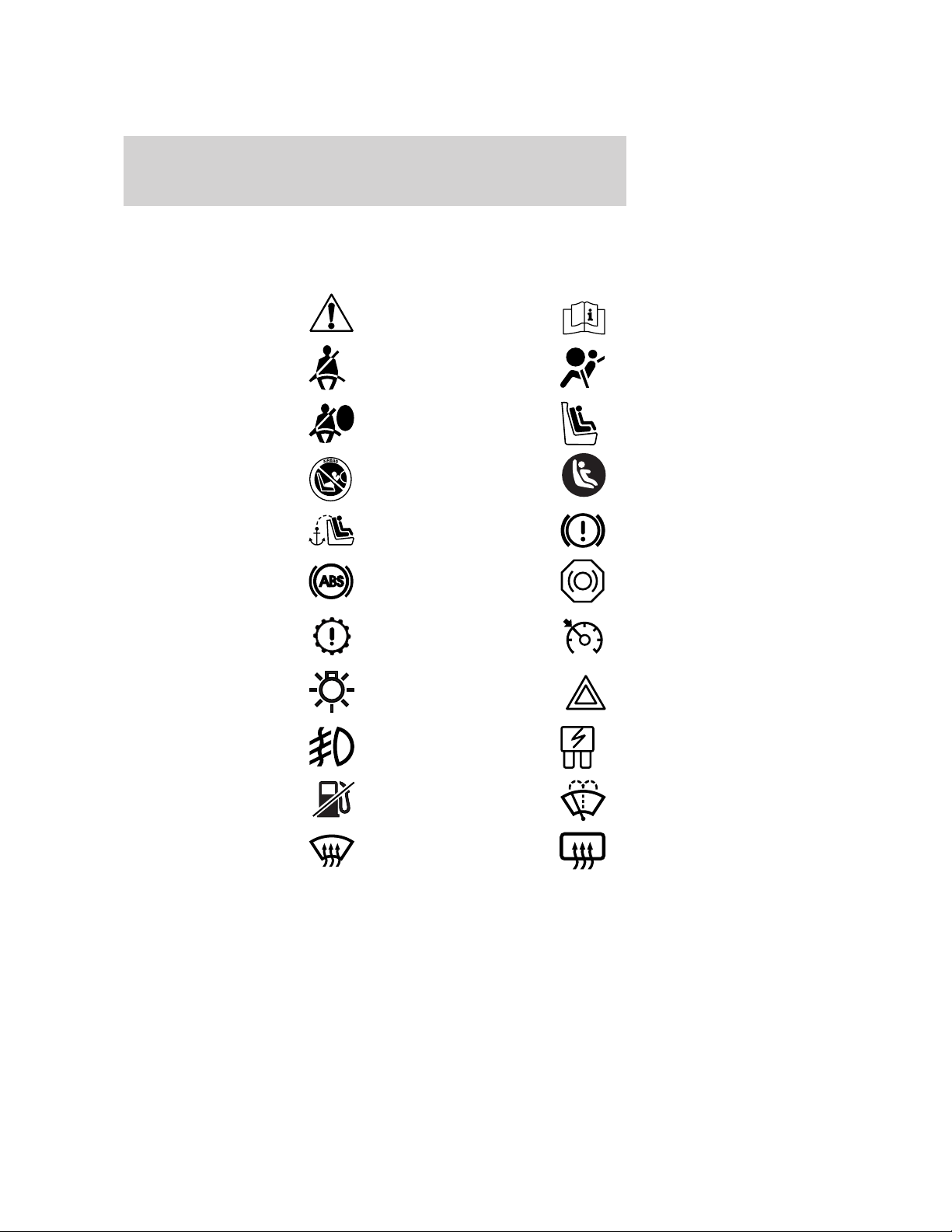
These are some of the symbols you may see on your vehicle.
Vehicle Symbol Glossary
Safety Alert
Fasten Safety Belt Air Bag-Front
Air Bag-Side Child Seat
Child Seat Installation
Warning
Child Seat Tether
Anchor
Anti-Lock Brake System
Powertrain Malfunction Speed Control
Master Lighting Switch Hazard Warning Flasher
Fog Lamps-Front Fuse Compartment
See Owner’s Guide
Child Seat Lower
Anchor
Brake System
Brake Fluid Non-Petroleum Based
Fuel Pump Reset Windshield Wash/Wipe
Windshield
Defrost/Demist
8
Rear Window
Defrost/Demist
2006 GT (gto)
Owners Guide (post-2002-fmt)
USA_English (fus)
Page 9
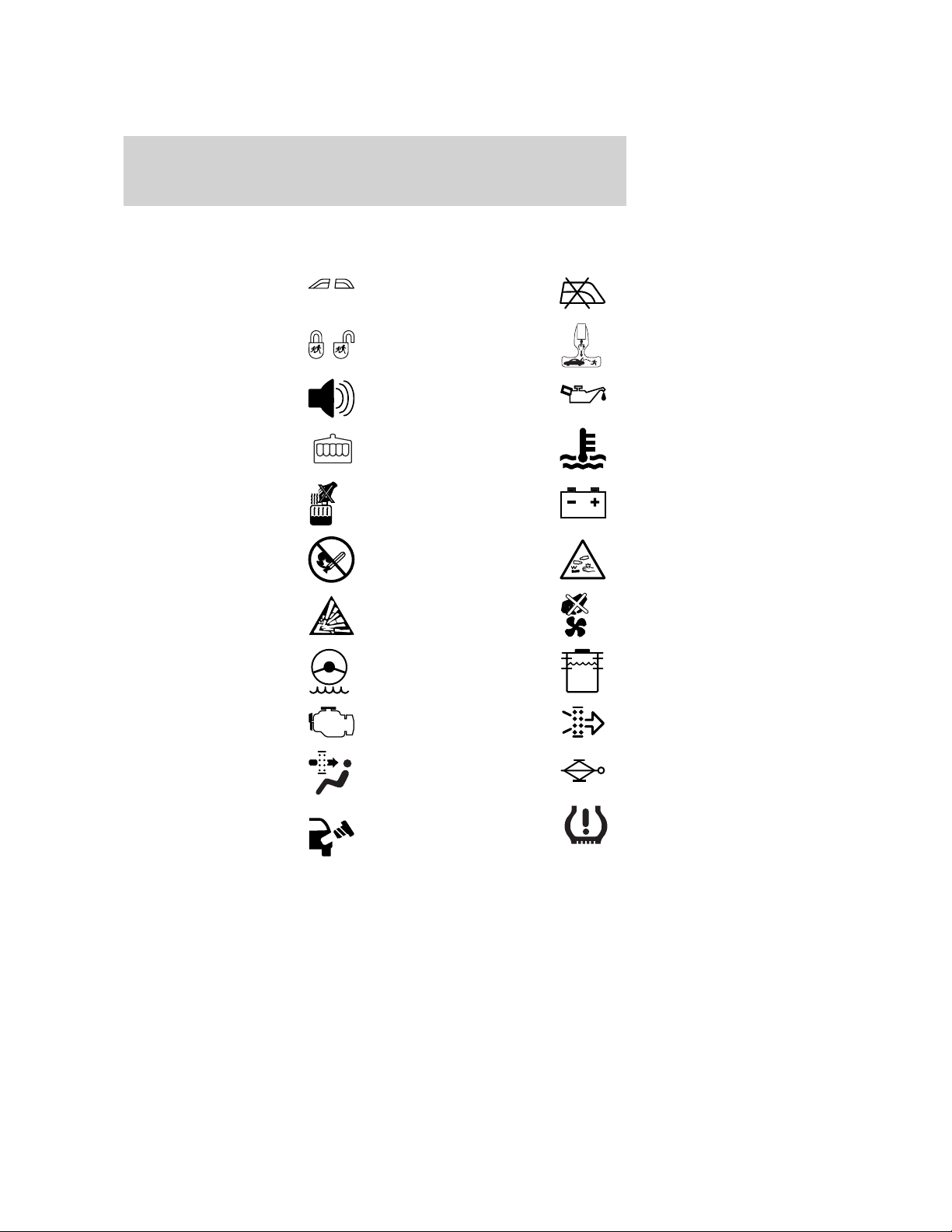
Vehicle Symbol Glossary
Introduction
Power Windows
Front/Rear
Child Safety Door
Lock/Unlock
Power Window Lockout
Interior Luggage
Compartment Release
Symbol
Panic Alarm Engine Oil
Engine Coolant
Engine Coolant
Temperature
Do Not Open When Hot Battery
Avoid Smoking, Flames,
or Sparks
Battery Acid
Explosive Gas Fan Warning
Power Steering Fluid
Maintain Correct Fluid
Level
Emission System Engine Air Filter
MAX
MIN
Passenger Compartment
Air Filter
Jack
Check fuel cap Low tire warning
2006 GT (gto)
Owners Guide (post-2002-fmt)
USA_English (fus)
9
Page 10
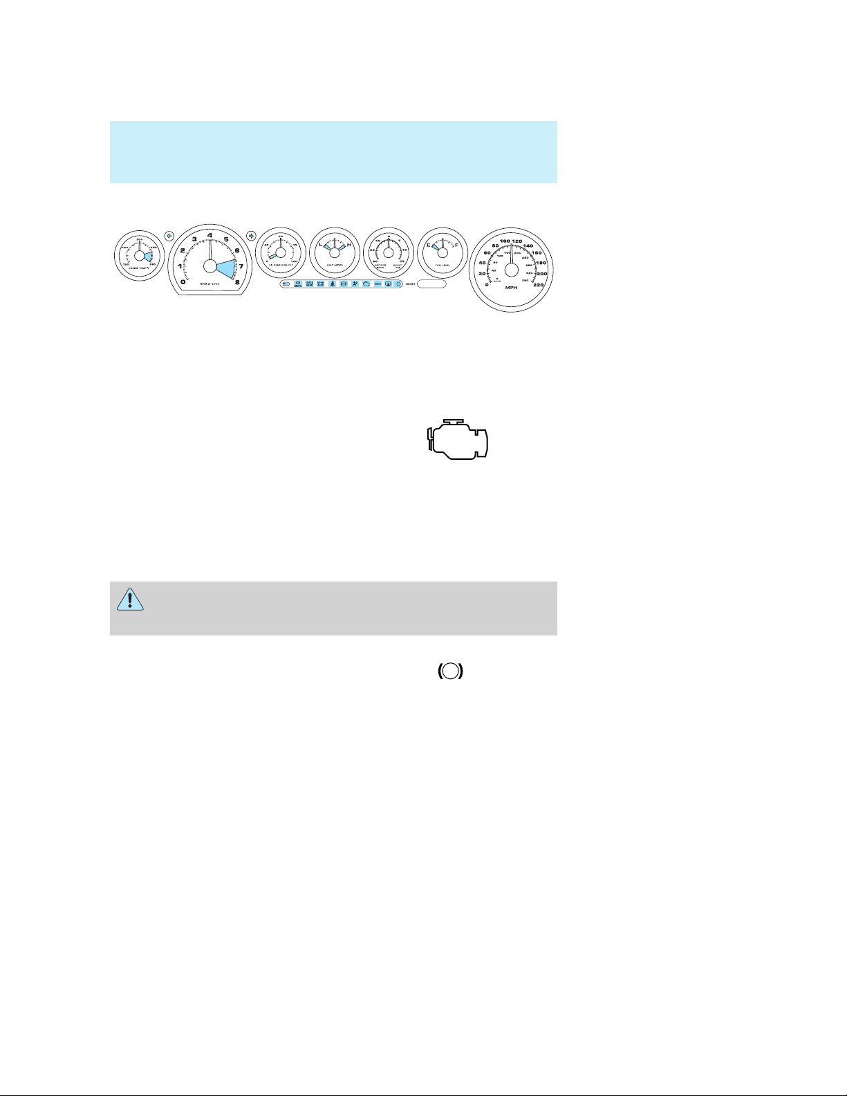
Instrument Cluster
Instrument Cluster
WARNING LIGHTS AND CHIMES
Warning lights and gauges can alert you to a vehicle condition that may
become serious enough to cause expensive repairs. A warning light may
illuminate when a problem exists with one of your vehicle’s functions.
Many lights will illuminate when you start your vehicle to make sure the
lights work. If any light remains on after starting the vehicle, have the
respective system inspected immediately.
Service engine soon: The Service
engine soon indicator light
illuminates when the ignition is first
turned to the ON position to check
the light function. Solid illumination after the engine is started indicates
the On Board Diagnostics System (OBD-II) has detected a malfunction.
Refer to On board diagnostics (OBD-II) in the Maintenance and
Specifications chapter. If the light is blinking, engine misfire is occurring
which could damage your catalytic converter. Drive in a moderate
fashion (avoid heavy acceleration and deceleration) and have your
vehicle serviced immediately.
Under engine misfire conditions, excessive exhaust temperatures
could damage the catalytic converter, the fuel system, interior
floor coverings or other vehicle components, possibly causing a fire.
Brake system warning light: To
confirm the brake system warning
light is functional, it will
momentarily illuminate when the
ignition is turned to the ON position
when the engine is not running or by applying the parking brake when
the ignition is turned to the ON position. If the brake system warning
light does not illuminate at this time, seek service immediately from your
dealership. Illumination after releasing the parking brake indicates low
brake fluid level and the brake system should be inspected immediately
by your servicing dealership.
10
!
BRAKE
2006 GT (gto)
Owners Guide (post-2002-fmt)
USA_English (fus)
Page 11
Instrument Cluster
Driving a vehicle with the brake system warning light on is
dangerous. A significant decrease in braking performance may
occur. It will take you longer to stop the vehicle. Have the vehicle
checked by your dealer immediately.
Anti-lock brake system:
Illuminates indicating an ABS fault.
If the lamp stays on for more than a
few seconds, then an ABS fault is
indicated, have the system serviced
immediately. Normal braking is still functional unless the brake warning
light also is illuminated.
Check gage: Illuminates when any
of the following conditions has
occurred:
• The engine coolant temperature
is high.
• The engine oil pressure is low.
• The fuel gauge is at or near empty.
• The charging system is malfunctioning.
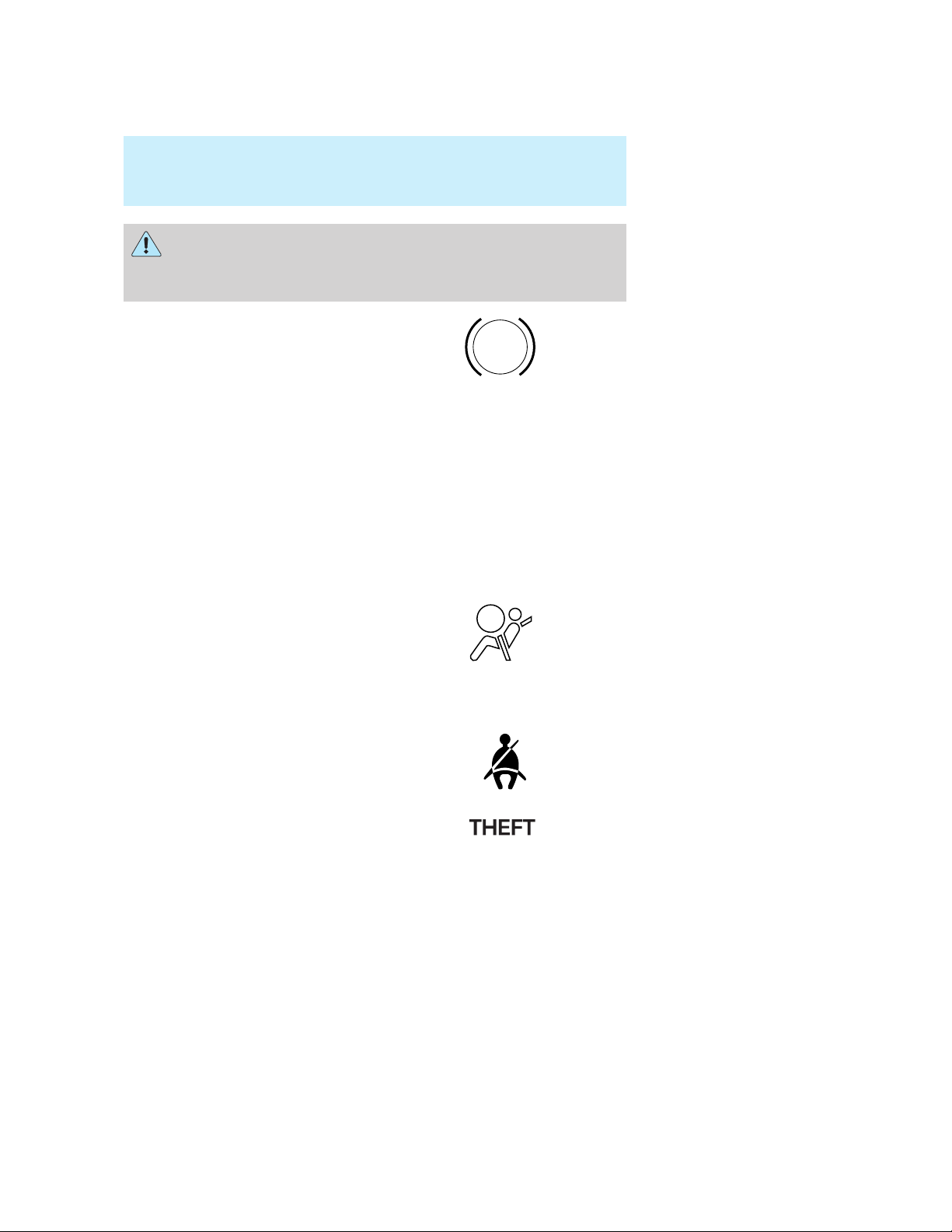
Air bag readiness: If this light fails
to illuminate when ignition is turned
to ON, continues to flash or remains
on, have the system serviced
immediately. A chime will also
sound when a malfunction in the supplemental restraint system has been
detected.
Safety belt: Reminds you to fasten
your safety belt. A chime will also
sound to remind you to fasten your
safety belt.
ABS
CHECK
GAGE
Anti-theft system: Flashes when
the Securilock娂 Passive Anti-theft
System has detected a fault.
2006 GT (gto)
Owners Guide (post-2002-fmt)
USA_English (fus)
11
Page 12
Instrument Cluster
Door ajar: Illuminates when the
ignition is in the ON position and
any door, trunk or the engine cover
is ajar.
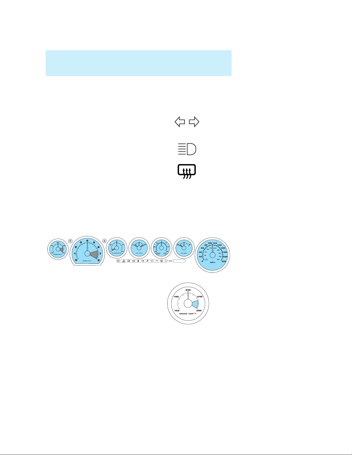
Turn signal: Illuminates when the
left or right turn signal or the hazard
lights are turned on. If the indicators
stay on or flash faster, check the tail lamps for proper function.
High beams: Illuminates when the
high beam headlamps are turned on.
Defrost: Illuminates when the rear
window defroster is turned on.
Key-in-ignition warning chime: Sounds when the key is left in the
ignition in the OFF/LOCK or ACCESSORY position and the driver’s door
is opened.
Headlamps on warning chime: Sounds when the headlamps or parking
lamps are on, the ignition is off (the key is not in the ignition) and the
driver’s door is opened.
GAUGES
DOOR
AJAR
Engine coolant temperature
gauge: Indicates engine coolant
temperature. At normal operating
temperature, the needle will be
outside the red section. If it enters
the red section, the engine is
overheating. Stop the vehicle as
soon as safely possible, switch
off the engine and let the engine cool.
12
2006 GT (gto)
Owners Guide (post-2002-fmt)
USA_English (fus)
Page 13
Instrument Cluster
Never remove the coolant reservoir cap while the engine is
running or hot.
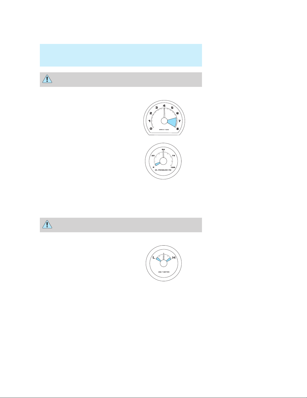
Tachometer: Indicates the engine
speed in revolutions per minute.
Driving with your tachometer
pointer continuously at the top of
the scale may damage the engine.
Engine oil pressure gauge:
Indicates engine oil pressure. If the
pointer drops to the red section
when the engine is running, stop
your vehicle as soon as possible,
shut off the engine and check the
oil tank level. Add oil if necessary.
Do not continue to operate your
engine as long as the pointer is in the red section. Otherwise, your
engine may be severely damaged.
If the gauge indicates zero or very low oil pressure (needle in the
red section) stop the vehicle and engine as soon as safe to do so
and check the engine oil tank level.
After running, the engine may be hot. Allow the engine to cool
before handling any components.
Voltmeter gauge: Measures the
battery charging voltage. If the
pointer moves above or below the
normal operating range under
normal vehicle operation, have your
vehicle’s electrical system checked.
2006 GT (gto)
Owners Guide (post-2002-fmt)
USA_English (fus)
13
Page 14
Instrument Cluster
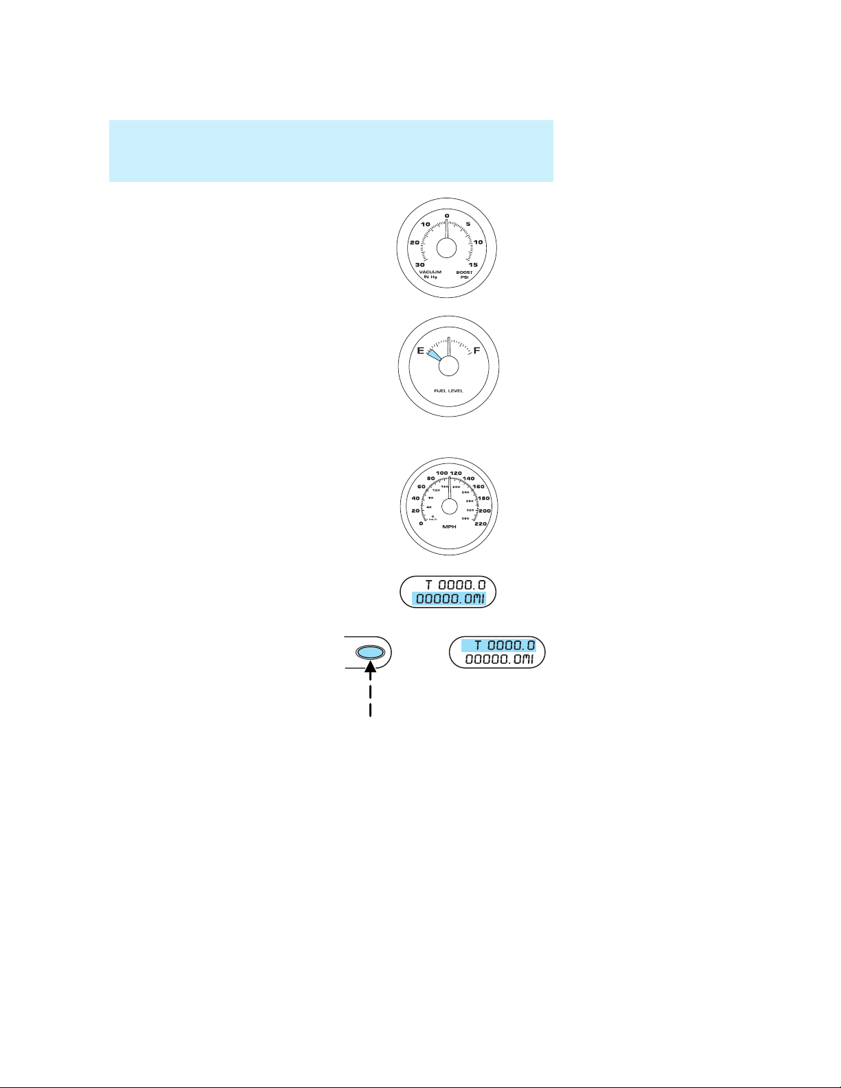
Boost/Vac gauge: Boost VAC shows
that supercharger boost and engine
vacuum are functioning properly. If
no boost or reduced boost is shown,
have engine checked.
Fuel gauge: Indicates
approximately how much fuel is left
in the fuel tank (when the ignition
is in the ON position). The fuel
gauge may vary slightly when the
vehicle is in motion or on a grade.
Refer to Filling the tank in the
Maintenance and Specifications
chapter for more information.
Speedometer: Indicates the
current vehicle speed.
Odometer: Registers the total miles
of the vehicle.
Trip odometer: Registers the miles
of individual journeys. To reset,
press and hold the button.
14
2006 GT (gto)
Owners Guide (post-2002-fmt)
USA_English (fus)
Page 15
Entertainment Systems
Entertainment Systems
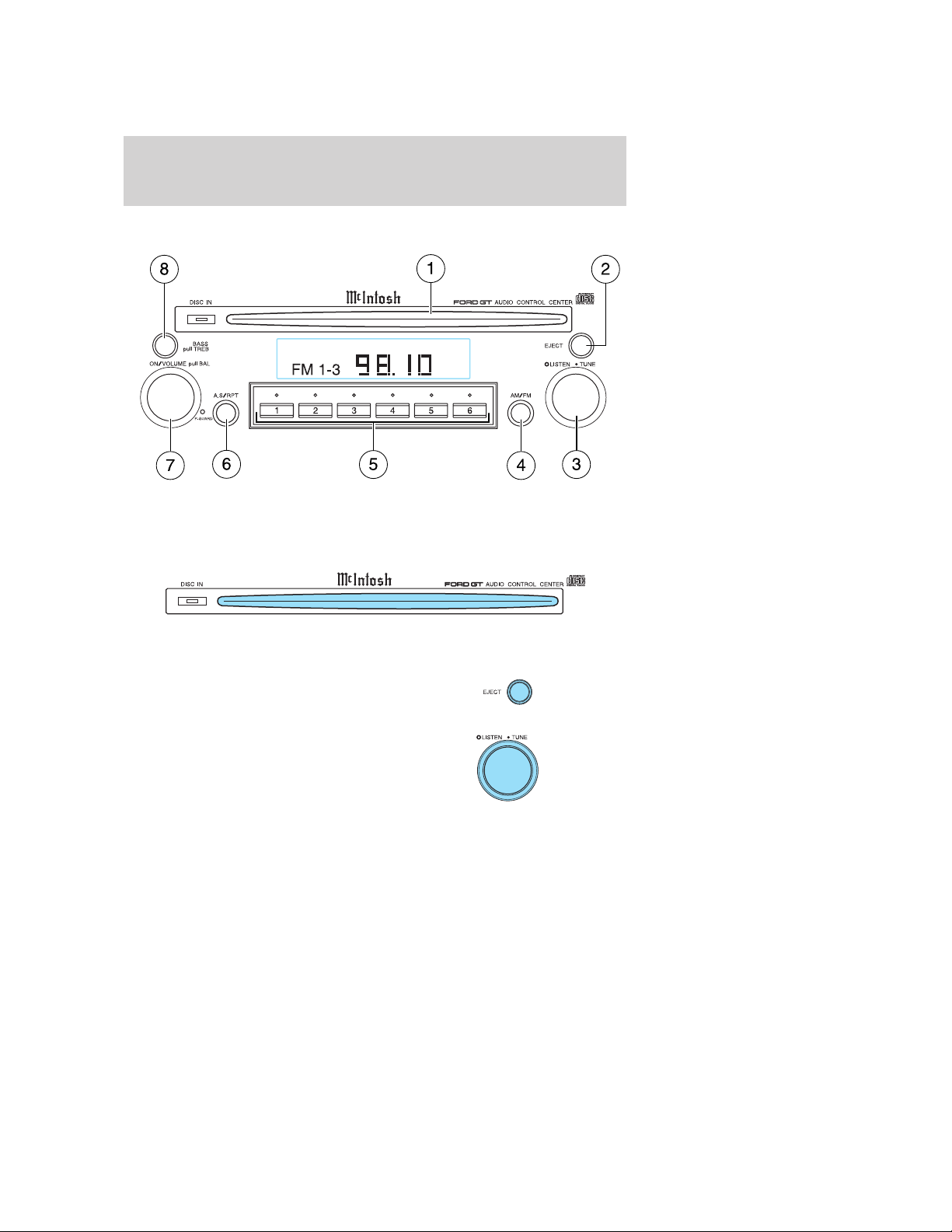
AM/FM MCINTOSH CD SYSTEM
A flashing anti-theft indicator (Disc in lamp), may be activated
and de-activated by pressing and holding the CD Eject control for
two seconds or more with the radio turned off.
1. CD door: Insert a CD label side up. Once loaded, the “Disc in”
indicator light will illuminate and playback begins automatically.
2. Eject: Press to eject a CD when
the power is on or off.
3. Listen/Tune: In radio mode, turn
and release the inner ring right or
left to incrementally tune radio
frequency up or down. Hold the ring
at the right or left tune position for
over a second to seek-up or
seek-down. In CD mode, turn and release the inner ring to select a
desired track. To change modes (Radio, CD, AUX), turn and release the
outer ring. Each time you turn and release the outer ring, the mode will
change and appear on the display. The AUX mode is inoperative for this
application.
15
2006 GT (gto)
Owners Guide (post-2002-fmt)
USA_English (fus)
Page 16
Entertainment Systems
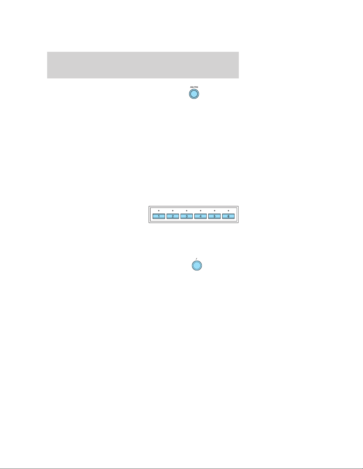
4. AM/FM: Press to select a
frequency band
(FM1/FM2/FM3/AM). The selected
band appears in the display.
Displaying the Clock:While pressing and holding the AM/FM band
control, press and release the #4 preset control. Each time this operation
is performed, the display will toggle between the selected mode (Radio,
CD) and clock mode.
Setting the Clock: Set the display to clock mode. (Press and hold
AM/FM while you press and release the #4 preset control. Do this until
the time is displayed.) To set the time, press and hold AM/FM again
while pressing and holding the #4 preset control for three seconds or
longer. The clock display will flash. Turn and release the TUNE control
to the right to advance the minutes incrementally. Turn and hold to
advance the minutes continually. Turn and release the TUNE control to
the left to advance the hours incrementally. Turn and hold to advance
the hours continually. When the correct time is set, press AM/FM to
confirm the current time.
5. Memory presets: In radio mode,
use to select stored stations. A total
of 24 stations can be stored in your
system — six in each band
(FM1/FM2/FM3/AM). Turn the TUNE control to select a station. Then
press and hold the desired memory preset. The sound will mute. When
the station is stored, the sound will return and the indicator light above
the control will illuminate.
A.S
6. A.S./RPT: (Autostore and
Repeat): In radio mode, this control
automatically stores the strongest
radio stations on the frequency
band. Select the desired frequency band (FM1/FM2/FM3/AM), then press
and hold A.S until AS appears in the display to indicate that the stations
have been stored. Any previously stored stations will be erased as the
new ones are saved. In CD mode, press the button to play the current
track repeatedly. RPT will appear in the display. Press again for normal
CD operation.
RPT
16
2006 GT (gto)
Owners Guide (post-2002-fmt)
USA_English (fus)
Page 17
Entertainment Systems
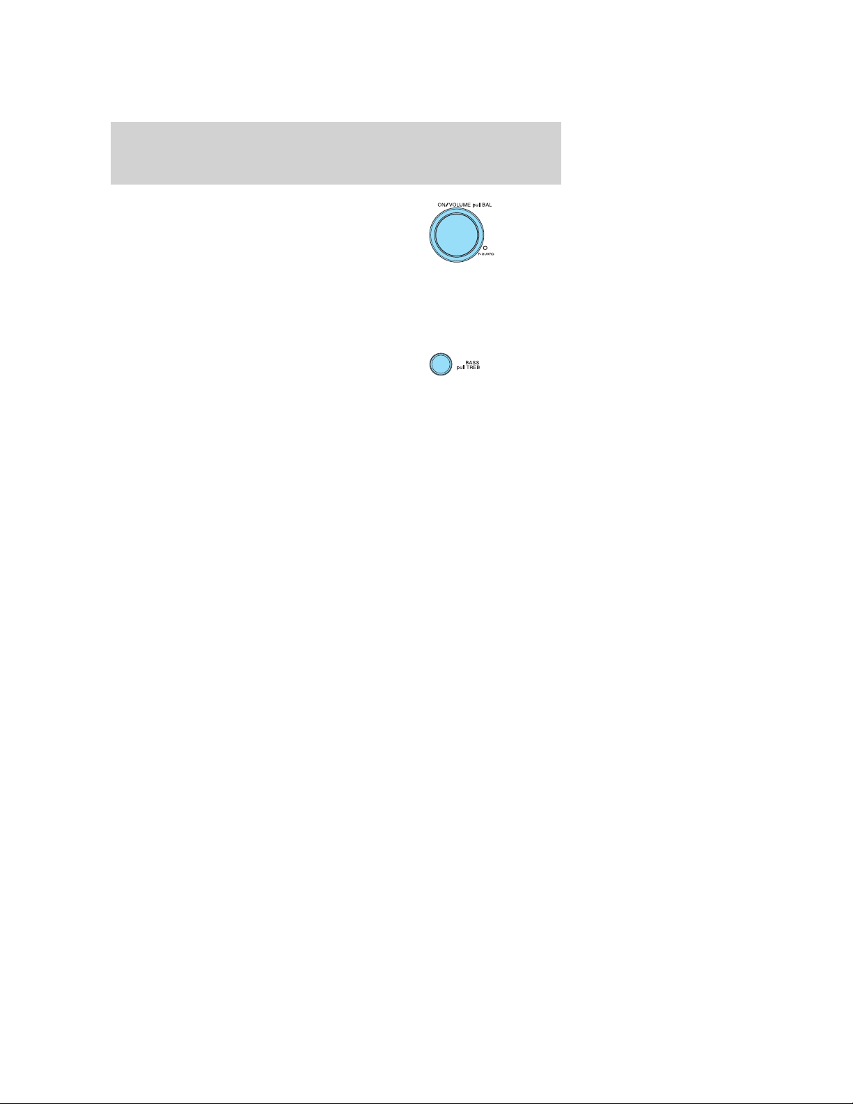
7. ON/OFF/Volume/Bal: Turn outer
ring of the control to the right to
turn the system ON. Once ON, turn
to the right to increase the volume,
turn to the left to decrease the
volume. To turn the system OFF,
turn the control fully to the left until the display turns off. For Balance
adjustment, pull the control out and turn to the left/right to shift the
sound between the left and right speakers. After adjustment, push the
control back to the original position.
8. Bass/Treb: Press in and release
to extend the control for
adjustment. Turn the control
left/right to decrease/increase the amount of Bass. For Treble, pull the
extended control out further and turn to the left/right to
decrease/increase the amount of treble. After adjustment, push the
control in fully to hide the control.
Power Guard: The indicator illuminates when the audio system has
reached its maximum power output and the Power Guard system is
controlling overload distortion.
RADIO FREQUENCIES
AM and FM frequencies are established by the Federal Communications
Commission (FCC) and the Canadian Radio and Telecommunications
Commission (CRTC). Those frequencies are:
AM - 530, 540–1700, 1710 kHz
FM- 87.7, 87.9–107.7, 107.9 MHz
RADIO RECEPTION FACTORS
There are three factors that can effect radio reception:
• Distance/strength: The further you travel from an FM station, the
weaker the signal and the weaker the reception.
• Terrain: Hills, mountains, tall buildings, power lines, electric fences,
traffic lights and thunderstorms can interfere with your reception.
• Station overload: When you pass a broadcast tower, a stronger signal
may overtake a weaker one and play while the weak station frequency
is displayed.
2006 GT (gto)
Owners Guide (post-2002-fmt)
USA_English (fus)
17
Page 18

Entertainment Systems
CD/CD PLAYER CARE
Do:
• Handle discs by their edges only. Never touch the playing surface.
• Inspect discs before playing. Clean only with an approved CD cleaner
and wipe from the center out.
Don’t:
• Expose discs to direct sunlight or heat sources for extended periods
of time.
• Insert more than one disc into the CD player.
• Clean using a circular motion.
CD units are designed to play commercially pressed 4.75 in (12
cm) audio compact discs only. Due to technical incompatibility,
certain recordable and re-recordable compact discs may not
function correctly when used in Ford CD players. Irregular
shaped CDs, CDs with a scratch protection film attached, and CDs
with homemade paper (adhesive) labels should not be inserted
into the CD player. The label may peel and cause the CD to
become jammed. It is recommended that homemade CDs be
identified with permanent felt tip marker rather than adhesive
labels. Ballpoint pens may damage CDs. Please contact your
dealer for further information.
AUDIO SYSTEM WARRANTY AND SERVICE
Refer to the Warranty Guide for audio system warranty information. If
service is necessary, see your dealer or qualified technician.
18
2006 GT (gto)
Owners Guide (post-2002-fmt)
USA_English (fus)
Page 19
Climate Controls
Climate Controls
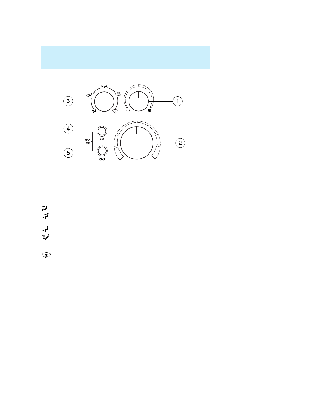
MANUAL A/C SYSTEM
1. Fan speed adjustment: Controls the volume of air circulated in the
vehicle.
2. Temperature selection: Controls the temperature of the airflow in
the vehicle.
3. Air flow selections: Controls the direction of the airflow in the
vehicle. See the following for a brief description on each control.
: Distributes air through the instrument panel vents.
: Distributes air through the instrument panel vents and the floor
vents.
: Distributes air through the floor vents.
: Distributes air through the windshield defroster vents and floor
vents. The system will automatically provide outside air to reduce
window fogging.
: Distributes outside air through the windshield defroster vents to
clear ice or fog from the windshield. The system will automatically
provide outside air to reduce window fogging.
4. A/C: Press and hold down briefly to engage/disengage. Uses outside or
recirculated air to cool the vehicle. Engages automatically in MAX A/C,
Defrost and Floor/Defrost. The A/C indicator light will illuminate in MAX
A/C mode and may or may not illuminate in Defrost, Floor/Defrost modes
depending on the previous selections. Note: A/C cannot be activated
without the fan speed adjustment being activated.
2006 GT (gto)
Owners Guide (post-2002-fmt)
USA_English (fus)
19
Page 20
Climate Controls
5. Recirculated air: Used to select fresh or recirculated air operation.
May also help reduce undesired outside odors from reaching the interior
of the vehicle. Press and hold down briefly to engage/disengage. To
reduce humidity inside the vehicle, turn recirculation off. Note: The
indicator light will be on when in recirculate mode, and will reduce the
amount of time to cool down the interior of the vehicle with A/C.
OPERATING TIPS
• To reduce fog build up on the windshield during humid weather, place
the air flow selector in the
• To demist the side glass, place the air flow selector in the
position and aim the outboard panel vents toward the side glass.
• To reduce humidity build up inside the vehicle:
during cold weather, do not drive with the air flow selector in the
OFF or MAX A/C position.
during warm weather, do not drive with the air flow selector in the
OFF position.
• Remove any snow, ice or leaves from the air intake area at the base of
the windshield.
Do not place objects on top of the instrument panel as these
objects may become projectiles in a collision or sudden stop.
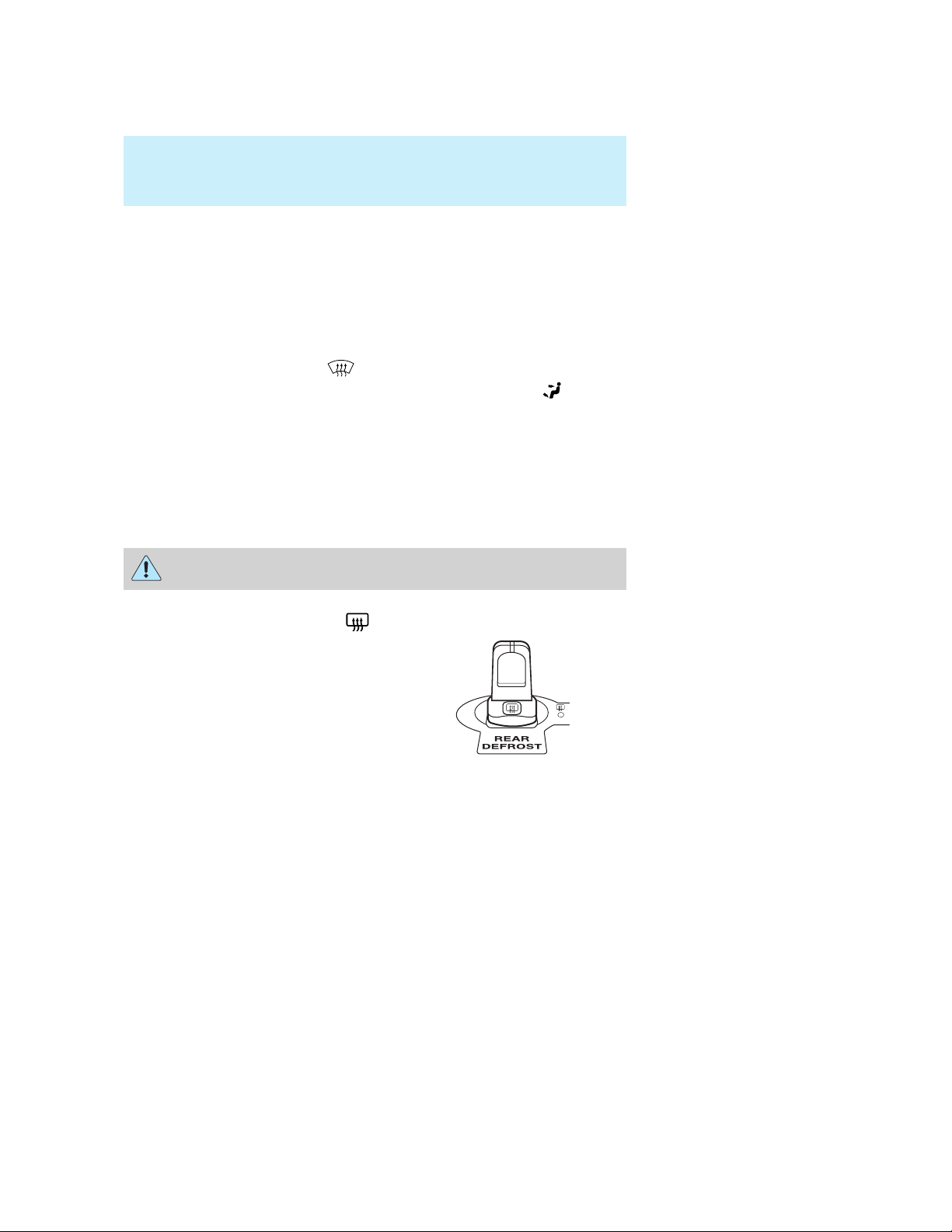
REAR WINDOW DEFROSTER
Ensure that the ignition is in the 3
(ON) position. In order to clear the
rear window of thin ice and fog,
push the control forward to activate
the rear window defroster. While the
defroster is active, the yellow
indicator lamp will be illuminated.
position.
The rear window defroster turns off automatically after 10 minutes or
when the ignition is turned to the 1 (OFF/LOCK) position. To manually
deactivate the rear window defroster before 10 minutes, push the control
forward again (the indicator lamp will turn off).
Do not use razor blades or other sharp objects to clean the inside
of the rear window or to remove decals from the inside of the
rear window. This may cause damage to the heated grid lines and
will not be covered by your warranty.
20
2006 GT (gto)
Owners Guide (post-2002-fmt)
USA_English (fus)
Page 21

Lights
HEADLAMP CONTROL
Pull the control rearward once to
turn on your parking lamps. Push it
forward to turn on your headlamps.
To turn the headlamps and parking
lamps off, put the control in the
center detent.
Foglamp control
The fog lamps can only be turned
on when the headlamp control is in
the parking lamp or headlamp
position.
Press the foglamp control forward to
activate the fog lamps. When the
highbeams are activated, the fog
lamps will not operate.
Pull the fog lamp control back to center to deactivate the fog lamps.
Lights
High beams
Pull the lever toward you to
activate. Pull the lever towards you
to deactivate.
Flash to pass
Pull toward you slightly to activate
and release to deactivate.
21
2006 GT (gto)
Owners Guide (post-2002-fmt)
USA_English (fus)
Page 22
Lights
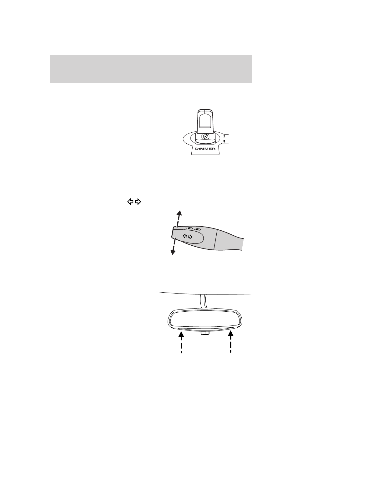
PANEL DIMMER CONTROL
Use to adjust the brightness of the instrument panel.
• Push the control forward to
brighten.
• Pull the control back to dim.
AIMING THE HEADLAMPS
The headlamps on your vehicle are properly aimed at the assembly plant.
If your vehicle has been in an accident the alignment of your headlamps
should be checked by a qualified service technician.
TURN SIGNAL CONTROL
• Push down to activate the left
turn signal.
• Push up to activate the right turn
signal.
INTERIOR LAMPS
Map lamps
The map lamps and controls are
located on the rearview mirror.
Press the controls on the bottom of
the mirror to activate the lamps.
22
2006 GT (gto)
Owners Guide (post-2002-fmt)
USA_English (fus)
Page 23
Lights
BULBS
Replacing exterior bulbs
Check the operation of all of the bulbs periodically.
Using the right bulbs
Replacement bulbs are specified in the chart below. Headlamp bulbs
must be marked with an authorized “D.O.T.” for North America to ensure
lamp performance, light brightness, pattern and safe visibility. The
correct bulbs will not damage the lamp assembly or void the lamp
assembly warranty and will provide quality bulb burn time.
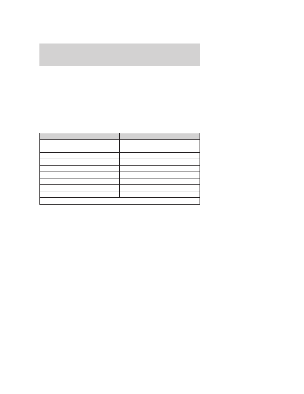
Function Trade number
Park/turn lamps (front) 5701 KA
Front side marker lamps W3W
Rear side marker lamps W3W
Headlamps HID (see dealer)
Rear stop/turn/tail lamps LED (see dealer)
Backup lamps 921
Rear license plate lamps 168
High-mount brake lamp See a dealer or qualified technician
Map lamps 3886X
To replace all instrument panel lights - see your dealer.
Interior bulbs
Check the operation of all of the bulbs periodically.
Replacing bulbs
For bulb replacement, see a dealer or qualified technician.
2006 GT (gto)
Owners Guide (post-2002-fmt)
USA_English (fus)
23
Page 24
Driver Controls
Driver Controls
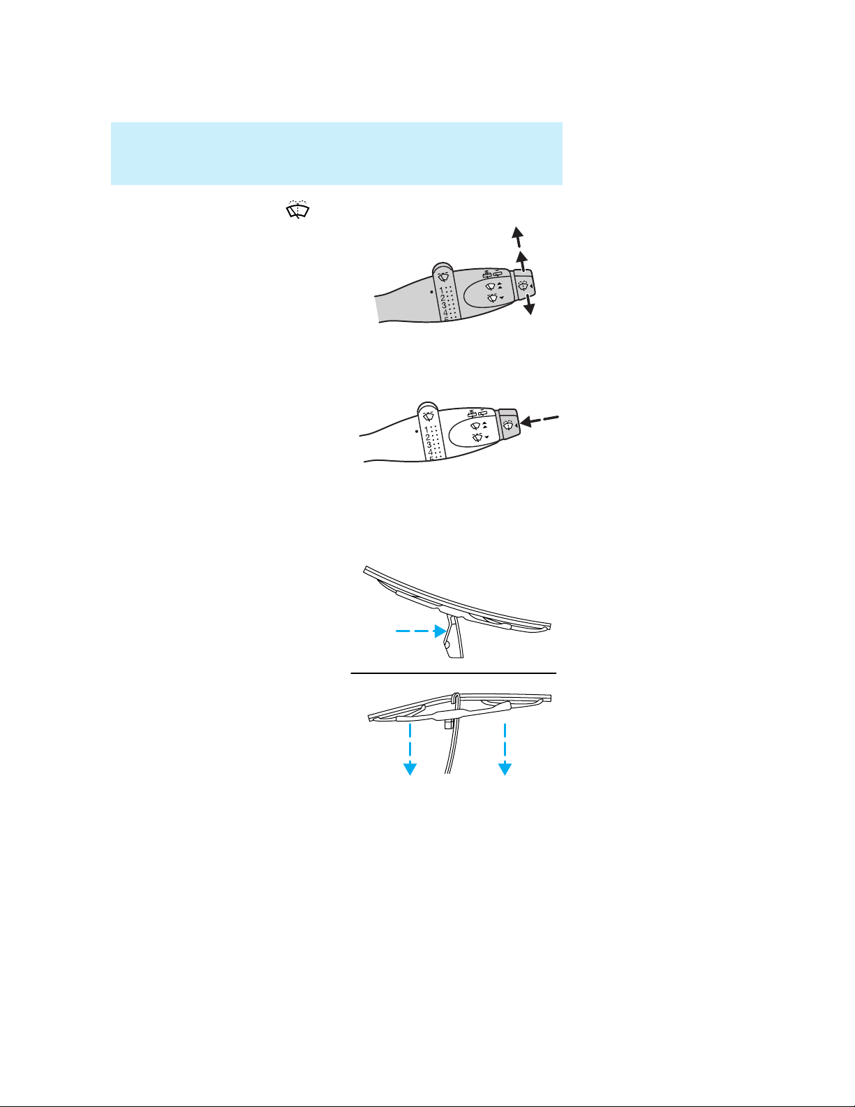
MULTI-FUNCTION LEVER
Windshield wiper: Move the lever
down for a single wipe.
For intermittent operation, move
control up one position and adjust
the rotary control to the desired
speed.
For normal operation, move control
up two positions.
For high speed operation, move control up three positions.
Mist function: To mist, push and
release the windshield washer
control quickly. The wipers will
cycle two or three times to clear the
windshield.
Windshield washer: To activate
the windshield washer, push the
windshield washer control. Release
control to stop washer fluid spray. The wipers will provide three wipes
after the wash is turned off.
CHANGING THE WIPER BLADES
1. Pull the wiper arm away from the
vehicle. Turn the blade at an angle
from the wiper arm. Push the lock
pin manually to release the blade
and pull the wiper blade down
toward the windshield to remove it
from the arm.
2. Attach the new wiper to the
wiper arm and press it into place
until a click is heard.
3. Replace wiper blades at least
once per year for optimum
performance.
4. Poor wiper quality can sometimes
be improved by cleaning the wiper
blades, refer to Window and wiper blades in the Cleaning chapter.
24
2006 GT (gto)
Owners Guide (post-2002-fmt)
USA_English (fus)
Page 25
Driver Controls
5. To prolong the life of the wiper blades, it is highly recommended to
scrape off the ice on the windshield before turning on the wipers. The
layer of ice has many sharp edges and can damage the micro edge of the
wiper rubber element.
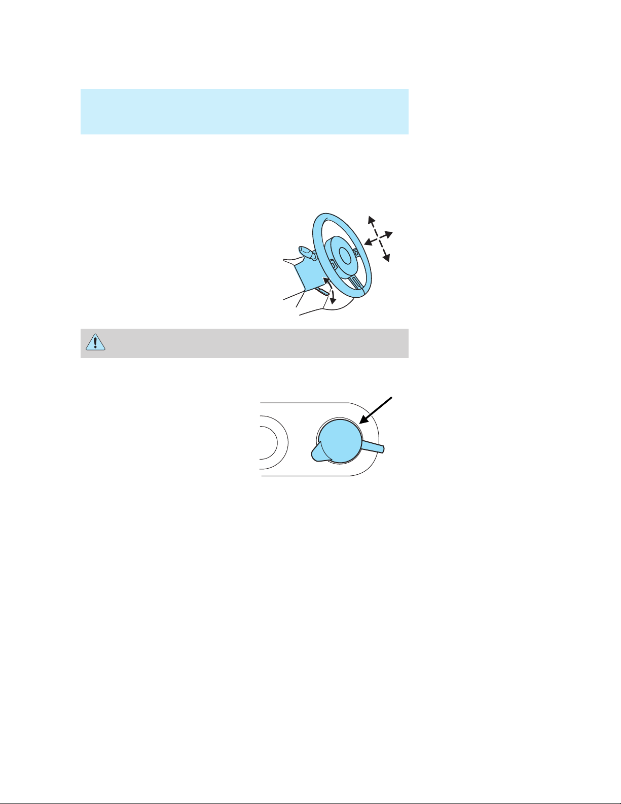
TILT STEERING COLUMN
Pull the locking lever down to tilt
and telescope the steering column
to the desired orientation. Return
the lever to its original position to
secure the wheel.
Never adjust the steering wheel when the vehicle is moving.
AUXILIARY POWER POINT
Power point outlets are designed
for accessory use only. Do not
hang any type of accessories or
accessory bracket from the their
plugs. Improper use of the
power point outlet can cause
damage not covered by your
warranty.
The maximum power the power
point can supply is 20A and 240
Watts. Exceeding these limits will result in a blown fuse.
Always keep the power point caps closed when not being used.
2006 GT (gto)
Owners Guide (post-2002-fmt)
USA_English (fus)
25
Page 26
Driver Controls
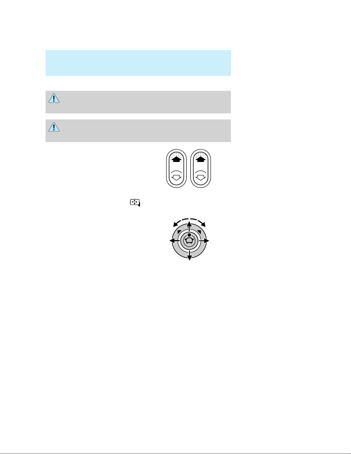
POWER WINDOWS
Do not leave children unattended in the vehicle and do not let
children play with the power windows. They may seriously injure
themselves.
When closing the power windows, you should verify they are free
of obstructions and ensure that children and/or pets are not in
the proximity of the window openings.
Press and hold the bottom part of
the rocker switch to open the
window. Press and hold the top part
of the rocker switch to close the
window.
POWER SIDE VIEW MIRRORS
To adjust your mirrors:
1. Rotate the control clockwise to
adjust the right mirror and rotate
the control counterclockwise to
adjust the left mirror.
2. Move the control in the direction
you wish to tilt the mirror.
3. Return to the center position to
lock mirrors in place.
CELL PHONE USE
The use of Mobile Communications Equipment has become increasingly
important in the conduct of business and personal affairs. However,
drivers must not compromise their own or others’ safety when using
such equipment. Mobile Communications can enhance personal safety
and security when appropriately used, particularly in emergency
situations. Safety must be paramount when using mobile communications
equipment to avoid negating these benefits.
26
2006 GT (gto)
Owners Guide (post-2002-fmt)
USA_English (fus)
Page 27
Driver Controls
Mobile Communication Equipment includes, but is not limited to cellular
phones, pagers, portable email devices, in-vehicle communications
systems, telematics devices and portable two-way radios.
A driver’s first responsibility is the safe operation of the vehicle.
The most important thing you can do to prevent a crash is to
avoid distractions and pay attention to the road. Wait until it is safe to
operate Mobile Communications Equipment.
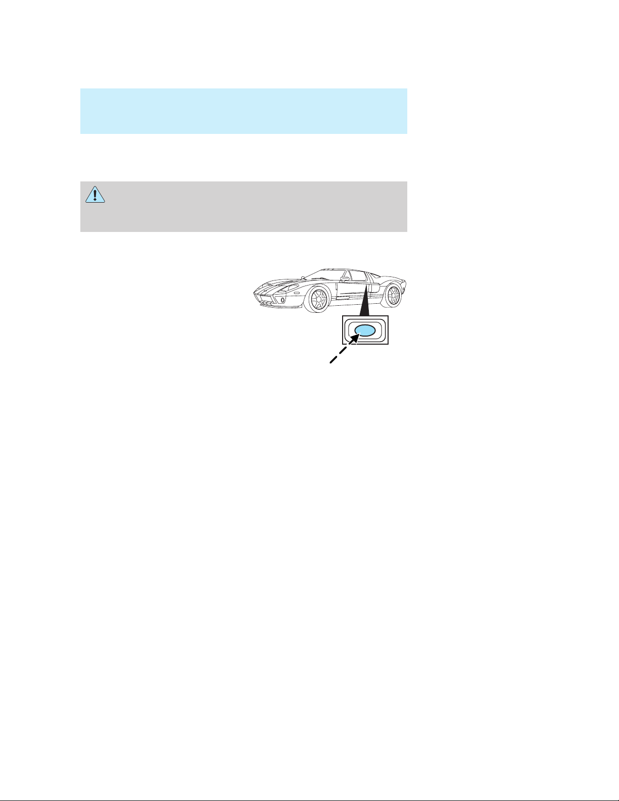
ELECTRIC DOOR RELEASE
To open the door, unlock (with the
remote entry transmitter) and push
the release button on the door.
Note: The vehicle doors may be
unlocked by using the remote entry
transmitter, however, in the event of
a low battery charge, the driver’s
door can be manually unlocked and
opened by inserting the key into the
door lock cylinder and turning
counterclockwise.
2006 GT (gto)
Owners Guide (post-2002-fmt)
USA_English (fus)
27
Page 28

Locks and Security
Locks and Security
KEYS
The key operates all locks on your vehicle. You should always carry a
second key with you in a safe place in case you require it in an
emergency.
Your keys are programmed to your vehicle; using a non-programmed key
will not permit your vehicle to start. If you lose your dealer supplied
keys, replacement keys are available through your authorized dealer.
POWER DOOR LOCKS
The power door lock controls are located on the driver and front
passenger door panels.
• Pressing the
control will unlock both doors.
• Pressing the
control will lock both doors.
The power door lock controls are
disabled 20 seconds after the ignition is turned to the 1 (OFF/LOCK)
position. Note: The door chime will sound once when the doors are
locked and twice when the doors are unlocked.
Autolock
The autolock feature will lock the vehicle’s doors when:
• both doors are closed,
• the ignition is in the 3 (ON) position,
• you shift into forward or reverse, and
• the vehicle speed is greater than 4 mph (7 km/h).
Note: The door chime will sound once to indicate the doors are locked.
Relock
The autolock feature repeats when:
• either door is opened then closed while the ignition is in the 3 (ON)
position, and
• you shift into forward or reverse, and
• the vehicle speed is greater than 4 mph (7 km/h).
portion of the
portion of the
28
2006 GT (gto)
Owners Guide (post-2002-fmt)
USA_English (fus)
Page 29

Locks and Security
To deactivate/reactivate the autolock feature using the power door
unlock control
You must complete steps 1-7 within 30 seconds or the procedure will
have to be repeated. If the procedure needs to be repeated, you must
wait 30 seconds. Note: The default setting for the autolock feature is
“disabled.”
1. Turn the ignition to the 3 (ON) position. Note: Both vehicle doors
must be closed during the activation/deactivation procedure.
2. Press the power door unlock control three times.
3. Turn the ignition from 3 (ON) position to the 1 (OFF/LOCK) position.
4. Press the power door unlock control three times.
5. Turn the ignition back to 3 (ON) position. The horn will chirp.
6. Press the unlock control, then press the lock control. The horn will
chirp once if autolock was deactivated or twice (one short and one long
chirp) if autolock was activated.
7. Turn the ignition to the 1 (OFF/LOCK) position. The horn will chirp
once to confirm the procedure is complete.
REMOTE ENTRY SYSTEM
This device complies with part 15 of the FCC rules and with RS-210 of
Industry Canada. Operation is subject to the following two conditions:
(1) This device may not cause harmful interference, and (2) This device
must accept any interference received, including interference that may
cause undesired operation.
Changes or modifications not expressly approved by the party
responsible for compliance could void the user’s authority to
operate the equipment.
The typical operating range for your remote entry transmitter is
approximately 33 feet (10 meters). A decrease in operating range could
be caused by:
• weather conditions,
• nearby radio towers,
• structures around the vehicle, or
• other vehicles parked next to your vehicle.
2006 GT (gto)
Owners Guide (post-2002-fmt)
USA_English (fus)
29
Page 30
Locks and Security
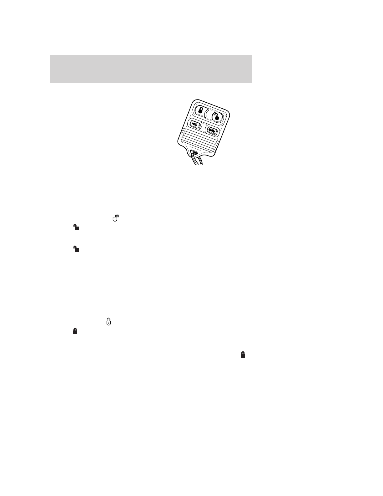
Your vehicle has an all-door remote entry system.
The all-door remote entry system
allows you to:
• lock or unlock both vehicle doors
without a key.
• arm and disarm the anti-theft
system. For more information on
the anti-theft system, refer to
SecuriLock娂 Passive Anti-theft
System in this chapter.
• open the luggage compartment
without a key.
• activate the panic alarm.
If there are problems with the remote entry system, make sure to take
ALL remote entry transmitters with you to the dealership in order to
aid in troubleshooting the problem.
Unlocking the doors
1. Press and release to unlock the driver’s door. Note: The interior
lamps will illuminate, the door chime will sound twice and the park
lamps will flash twice.
2. Press
The door chime will again sound twice and the park lamps will again
flash twice.
The remote entry system activates the illuminated entry feature. This
feature turns on the interior lamps for 25 seconds or until the ignition is
turned to the 3 (ON) position.
Note: The vehicle doors may be unlocked by using the remote entry
transmitter, however, in the event of a low battery charge, the door can
be manually unlocked and opened by inserting the key into the driver’s
door lock cylinder and turning counter clockwise.
and release again within three seconds to unlock both doors.
Locking the doors
• Press and release to lock both doors. Note: The parking lamps will
flash once.
If either of the doors, the luggage compartment or the engine cover are
not properly closed, the horn will make two quick chirps if you press
a second time and release.
30
2006 GT (gto)
Owners Guide (post-2002-fmt)
USA_English (fus)
Page 31

Locks and Security
This process will also activate the vehicle’s anti-theft system. For more
information on arming the anti-theft system, refer to SecuriLock娂
Passive Anti-theft System in this chapter.
Opening the luggage compartment
Press once to open the luggage compartment. Note: This feature
is inoperative with the ignition in the 1 (OFF/LOCK) position.
• The luggage compartment can be released using the remote entry
transmitter. It can also be unlatched manually by inserting the key
into the lock on the driver’s side front fender. Once the key is turned,
the aluminum release handle may be gently pulled to unlatch the
trunk. Use care when loading items into the luggage compartment to
ensure that the lid can be closed without binding.
• Ensure that the luggage compartment is closed and latched before
driving your vehicle. Failure to properly latch the luggage
compartment may cause objects to fall out or block the driver’s
forward view.
Sounding a panic alarm
Press
ignition to the 3 (ON) position to deactivate.
Note: The panic alarm will only operate when the ignition is in the 1
(OFF/LOCK) position.
to activate the alarm. Press the control again, or turn the
Replacing the battery
The remote entry transmitter uses one coin type three-volt lithium
battery CR2032 or equivalent.
To replace the battery:
1. Twist a thin coin between the two
halves of the remote entry
transmitter near the key ring. DO
NOT TAKE THE RUBBER COVER
AND CIRCUIT BOARD OFF THE
FRONT HOUSING OF THE
REMOTE ENTRY TRANSMITTER.
2006 GT (gto)
Owners Guide (post-2002-fmt)
USA_English (fus)
31
Page 32

Locks and Security
2. Do not wipe off any grease on the
battery terminals on the back
surface of the circuit board.
3. Remove the old battery. Note: Please refer to local regulations when
disposing of transmitter batteries.
4. Insert the new battery. Refer to the diagram inside the remote entry
transmitter for the correct orientation of the battery. Press the battery
down to ensure that the battery is fully seated in the battery housing
cavity.
5. Snap the two halves back together.
Note: Replacement of the battery will not cause the remote transmitter
to become deprogrammed from your vehicle. The remote transmitter
should operate normally after battery replacement.
Replacing lost remote entry transmitters
If you would like to have your remote entry transmitter reprogrammed
because you lost one, or would like to buy additional remote entry
transmitters, you can either reprogram them yourself, or take all
remote entry transmitters to your authorized dealer for
reprogramming.
How to reprogram your remote entry transmitters
You must have all remote entry transmitters (maximum of four)
available before beginning this procedure.
32
2006 GT (gto)
Owners Guide (post-2002-fmt)
USA_English (fus)
Page 33

Locks and Security
To reprogram the remote entry
transmitters:
1. Close both doors and fasten the driver’s seat belt to ensure conflicting
chimes do not sound during the procedure.
2. Put the key in the ignition.
3. Turn the key from the 1 (OFF/LOCK) position to the 3 (ON) position.
4. Cycle eight times rapidly (within 10 seconds) between the 1
(OFF/LOCK) and the 3 (ON) position. Note: The eighth turn must end
in the 3 (ON) position.
5. Within 20 seconds press any button on the remote entry transmitter.
Note: If more than 20 seconds have passed you will need to start the
procedure over again.
6. Repeat Step 5 to program each additional remote entry transmitter.
7. Turn the ignition to the 1 (OFF/LOCK) position after you have
finished programming all of the remote entry transmitters.
SECURILOCK姟 PASSIVE ANTI-THEFT SYSTEM
SecuriLock娂 passive anti-theft system is an engine immobilization
system. This system is designed to help prevent the engine from being
started unless a coded key programmed to your vehicle is used. The
use of the wrong type of coded key may lead to a “no-start” condition.
Your vehicle comes with two coded keys; additional coded keys may be
purchased from your dealer. The dealer can program your spare keys to
your vehicle or you can program the keys yourself. Refer to
Programming spare keys for instructions on how to program the coded
key.
Note: The SecuriLock娂 passive anti-theft system is not compatible with
non-Ford aftermarket remote start systems. Use of these systems may
result in vehicle starting problems and a loss of security protection.
2006 GT (gto)
Owners Guide (post-2002-fmt)
USA_English (fus)
33
Page 34

Locks and Security
Note: Large metallic objects, electronic devices that are used to
purchase gasoline or similar items, or a second coded key on the same
key chain may cause vehicle starting issues. You need to prevent these
objects from touching the coded key while starting the engine. These
objects will not cause damage to the coded key, but may cause a
momentary issue if they are too close to the key when starting the
engine. If a problem occurs, turn the ignition off, remove all objects on
the key chain away from the coded key and restart the engine.
Theft indicator
The theft indicator is located on the instrument panel, below the
Boost/Vac gauge.
• When the ignition is in the 3 (ON) position, the indicator will glow for
3 seconds, then turn off, to indicate normal system functionality.
If a problem occurs with the SecuriLock娂 system, the indicator will flash
rapidly or glow steadily when the ignition is in the 3 (ON) position. If this
occurs, the vehicle should be taken to an authorized dealer for service.
Replacement keys
If your keys are lost or stolen and you don’t have an extra coded key,
you will need to have your vehicle towed to a dealership. The key codes
need to be erased from your vehicle and new coded keys will need to be
programmed.
Replacing coded keys can be very costly. Store an extra programmed key
away from the vehicle in a safe place to help prevent any
inconveniences. Please visit an authorized dealer to purchase additional
spare or replacement keys.
Programming spare keys
You can program your own coded keys to your vehicle. Please read and
understand the entire procedure before you begin.
Tips:
• A maximum of eight keys can be coded to your vehicle.
• Only use SecuriLock娂 keys.
• You must have two previously programmed coded keys (keys that
already operate your vehicle’s engine) and the new unprogrammed
key(s) readily accessible.
If two previously programmed coded keys are not available, you must
•
take your vehicle to your dealer to have the spare key(s) programmed.
34
2006 GT (gto)
Owners Guide (post-2002-fmt)
USA_English (fus)
Page 35

Locks and Security
1. Insert a previously programmed
coded key into the ignition.
2. Turn the ignition from the 1 (OFF/LOCK) position to the 3 (ON)
position. Keep the ignition in the 3 (ON) position for at least one second,
but no more than 10 seconds.
3. Turn the ignition to the 1 (OFF/LOCK) position.
4. Remove the previously programmed coded key from the ignition.
5. Within ten seconds of removing the previously programmed coded key,
insert the other previously programmed coded key into the ignition.
6. Turn the ignition from the 1 (OFF/LOCK) position to the 3 (ON)
position. Keep the ignition in the 3 (ON) position for at least one second
but not more than 10 seconds.
7. Turn the ignition to the 1 (OFF/LOCK) position.
8. Remove the previously programmed coded key from the ignition.
9. Within twenty seconds of removing the previously programmed coded
key, insert the unprogrammed key (new/valet key) into the ignition.
10. Turn the ignition from the 1 (OFF/LOCK) position to the 3 (ON)
position. Keep the ignition in the 3 (ON) position for at least one second,
but no more than 10 seconds.
11. Your new, unprogrammed key is now programmed.
If the key has been successfully programmed it will start the vehicle’s
engine and the theft indicator light will illuminate for three seconds and
then go out.
If the key was not successfully programmed, it will not start your
vehicle’s engine and the theft indicator light will flash on and off, or stay
on for more than three seconds. If failure repeats, bring your vehicle to
your dealer to have the new key(s) programmed.
To program additional new unprogrammed key(s), repeat this procedure
from Step 1 for each additional key.
2006 GT (gto)
Owners Guide (post-2002-fmt)
USA_English (fus)
35
Page 36

Locks and Security
PERIMETER ALARM SYSTEM
The perimeter anti-theft system will warn you in the event of an
unauthorized entry to your vehicle.
If there is any potential perimeter anti-theft problem with your vehicle,
ensure ALL remote entry transmitters are taken to the dealership to
aid in troubleshooting.
Arming the system
When armed, this system will respond if unauthorized entry is
attempted. When unauthorized entry occurs, the system will flash the
park/turn lamps and will sound the horn.
The system is ready to arm whenever the key is removed from the
ignition. Either of the following actions will prearm the alarm system:
• Press the
• Lock the doors with the key in the key cylinder.
• Open a door and press the power door lock control to lock all the
doors, and then close the door.
Disarming the system
You can disarm the system by any of the following actions:
• Unlock the doors by pressing the
transmitter.
• Unlock the doors with a key. Turn the key full travel (toward the front
of the vehicle) to ensure the alarm disarms.
control on the remote entry transmitter.
control on your remote entry
Triggering the anti-theft system
The armed system will be triggered if either door, the luggage
compartment or the engine cover is opened without using the remote
entry transmitter.
36
2006 GT (gto)
Owners Guide (post-2002-fmt)
USA_English (fus)
Page 37

ELECTRIC DOOR RELEASE
To open the door, unlock (with the
remote entry transmitter) and push
the release button on the door.
Note: The vehicle doors may be
unlocked by using the remote entry
transmitter, however, in the event of
a low battery charge, the driver’s
door can be manually unlocked and
opened by inserting the key into the
door lock cylinder and turning
counterclockwise.
Locks and Security
2006 GT (gto)
Owners Guide (post-2002-fmt)
USA_English (fus)
37
Page 38

Seating and Safety Restraints
Seating and Safety Restraints
SEATING
Notes:
Reclining the seatback can cause an occupant to slide under the
seat’s safety belt, resulting in severe personal injuries in the
event of a collision.
Do not pile cargo higher than the seatbacks to reduce the risk of
injury in a collision or sudden stop.
Adjusting the front manual seat
Never adjust the driver’s seat or seatback when the vehicle is
moving.
Always drive and ride with your seatback upright and the lap
belt snug and low across the hips.
Lift handle to move seat forward or
backward.
38
2006 GT (gto)
Owners Guide (post-2002-fmt)
USA_English (fus)
Page 39

Seating and Safety Restraints
Rotate the control to adjust
seatback.
SAFETY RESTRAINTS
Safety restraints precautions
To maximize restraint system effectiveness, the driver and
passenger seat must be in the upright position and the lap belt
must be snug and low across the hips while the vehicle is moving.
To reduce the risk of injury, make sure children sit where they
can be properly restrained.
Never let a passenger hold a child on his or her lap while the
vehicle is moving. The passenger cannot protect the child from
injury in a collision.
All occupants of the vehicle, including the driver, should always
properly wear their safety belts, even when an air bag
supplemental restraint system (SRS) is provided.
It is extremely dangerous to ride in a cargo area, inside or
outside of a vehicle. In a collision, people riding in these areas
are more likely to be seriously injured or killed. Do not allow people to
ride in any area of your vehicle that is not equipped with seats and
safety belts. Be sure everyone in your vehicle is in a seat and using a
safety belt properly.
2006 GT (gto)
Owners Guide (post-2002-fmt)
USA_English (fus)
39
Page 40

Seating and Safety Restraints
In a rollover crash, an unbelted person is significantly more likely
to die than a person wearing a safety belt.
Each seating position in your vehicle has a specific safety belt
assembly which is made up of one buckle and one tongue that
are designed to be used as a pair. 1) Use the shoulder belt on the
outside shoulder only. Never wear the shoulder belt under the arm. 2)
Never swing the safety belt around your neck over the inside shoulder.
3) Never use a single belt for more than one person.
Combination lap and shoulder belts
1. Insert the belt tongue into the
proper buckle (the buckle closest to
the direction the tongue is coming
from) until you hear a snap and feel
it latch. Make sure the tongue is
securely fastened in the buckle.
2. To unfasten, push the release
button and remove the tongue from
the buckle.
Energy Management Feature
The safety belts in the vehicle are combination lap and shoulder belts.
• This vehicle has a seat belt system with an energy management
feature at the front outboard seating positions to help further reduce
the risk of injury in the event of a head-on collision.
40
2006 GT (gto)
Owners Guide (post-2002-fmt)
USA_English (fus)
Page 41

Seating and Safety Restraints
• This seat belt system has a retractor assembly that is designed to pay
out webbing in a controlled manner. This feature is designed to help
reduce the belt force acting on the occupant’s chest.
The safety restraints in the vehicle are combination lap and shoulder
belts. The safety belts have two types of locking modes described below.
Vehicle sensitive mode
The vehicle sensitive mode is the normal retractor mode, allowing free
shoulder belt length adjustment to your movements and locking in
response to vehicle movement. For example, if the driver brakes
suddenly or turns a corner sharply, or the vehicle receives an impact of
approximately 5 mph (8 km/h) or more, the combination safety belts will
lock to help reduce forward movement of the driver and passengers.
Automatic locking mode
The automatic locking mode is not available on the driver safety belt.
When to use the automatic locking mode
In this mode, the shoulder belt is automatically pre-locked. The belt will
still retract to remove any slack in the shoulder belt. The automatic
locking mode is not available on the driver safety belt.
This mode should be used any time a child safety seat is installed in a
passenger front seating position. Refer to Safety restraints for children
or Safety seats for children later in this chapter.
How to use the automatic locking mode
• Buckle the combination lap and
shoulder belt.
2006 GT (gto)
Owners Guide (post-2002-fmt)
USA_English (fus)
41
Page 42

Seating and Safety Restraints
• Grasp the shoulder portion and
pull downward until the entire
belt is pulled out.
• Allow the belt to retract. As the belt retracts, you will hear a clicking
sound. This indicates the safety belt is now in the automatic locking
mode.
How to disengage the automatic locking mode
Ford Motor Company recommends that all safety belt assemblies
and attaching hardware should be inspected by a qualified
technician after any collision. Safety belt assemblies not in use during a
collision should also be inspected and replaced if either damage or
improper operation is noted.
Disconnect the combination lap/shoulder belt and allow it to retract
completely to disengage the automatic locking mode and activate the
vehicle sensitive (emergency) locking mode.
After any vehicle collision, the front passenger seat belt systems
must be checked by a qualified technician to verify that the
“automatic locking retractor” feature for child seats is still functioning
properly. In addition, all seat belts should be checked for proper
function.
BELT AND RETRACTOR ASSEMBLY MUST BE REPLACED if
the seat belt assembly “automatic locking retractor” feature or
any other seat belt function is not operating properly when checked
according to the procedures in Workshop Manual.
Failure to replace the Belt and Retractor assembly could
increase the risk of injury in collisions.
42
2006 GT (gto)
Owners Guide (post-2002-fmt)
USA_English (fus)
Page 43

Seating and Safety Restraints
Safety belt pretensioner
Your vehicle is equipped with safety belt pretensioners at the driver and
front passenger seating positions.
The safety belt pretensioner is a device which removes excess webbing
from the safety belt system. The safety belt pretensioner uses the same
crash sensor system as the front air bag supplemental restraint system
(SRS). When the safety belt pretensioner deploys, webbing from the lap
and shoulder belt is tightened. The driver and front passenger seat belt
system (including retractors and buckles) must be replaced if the vehicle
is involved in a collision that results in deployment of front air bags and
safety belt pretensioners. Refer to the Safety belt maintenance section
in this chapter.
Failure to replace the safety belt assembly under the above
conditions could result in severe personal injuries in the event of
a collision.
Safety belt warning light and indicator chime
The safety belt warning light illuminates in the instrument cluster and a
chime sounds to remind the occupants to fasten their safety belts.
Conditions of operation
If... Then...
The driver’s safety belt is not
buckled before the ignition
switch is turned to the ON
position...
The driver’s safety belt is
buckled while the indicator
light is illuminated and the
warning chime is sounding...
The driver’s safety belt is
buckled before the ignition
switch is turned to the ON
position...
The safety belt warning light
illuminates1-2 minutes and the
warning chime sounds 4-8 seconds.
The safety belt warning light and
warning chime turn off.
The safety belt warning light and
indicator chime will remain off.
2006 GT (gto)
Owners Guide (post-2002-fmt)
USA_English (fus)
43
Page 44

Seating and Safety Restraints
BeltMinder姟
The BeltMinder娂 feature is a supplemental warning to the safety belt
warning function. This feature provides additional reminders to the
driver that the driver’s safety belt is unbuckled by intermittently
sounding a chime and illuminating the safety belt warning lamp in the
instrument cluster.
If... Then...
The driver’s safety belt is not
buckled approximately 5
seconds after the safety belt
warning light has turned off
and the vehicle speed is over
about 4 mph (7 km/h)...
The driver’s safety belt is
buckled while the safety belt
indicator light is illuminated
and the safety belt warning
chime is sounding...
The driver’s safety belt is
buckled before the ignition
switch is turned to the ON
position...
The following are reasons most often given for not wearing safety belts
(All statistics based on U.S. data):
The BeltMinder娂 feature is activated the safety belt warning light
illuminates and the warning chime
sounds for 6 seconds every 30
seconds, repeating for approximately 5
minutes or until safety belt is buckled.
The BeltMinder娂 feature will not
activate.
The BeltMinder娂 feature will not
activate.
Reasons given... Consider...
“Crashes are rare events” 367 00 crashes occur every day.
The more we drive, the more we are
exposed to “rare” events, even for
good drivers. 1 in 4 of us will be
seriously injured in a crash during
our lifetime.
“I’m not going far” 3of4fatal crashes occur within 25
miles of home.
44
2006 GT (gto)
Owners Guide (post-2002-fmt)
USA_English (fus)
Page 45

Seating and Safety Restraints
Reasons given... Consider...
“Belts are uncomfortable” We design our safety belts to enhance
comfort. If you are uncomfortable - try
different positions for the seatback
which should be as upright as
possible; this can improve comfort.
“I was in a hurry” Prime time for an accident.
BeltMinder娂 reminds us to take a few
seconds to buckle up.
“Safety belts don’t work” Safety belts, when used properly,
reduce risk of death to front seat
occupants by 45% in cars, and by
60% in light trucks.
“Traffic is light” Nearly 1 of 2 deaths occur in
single-vehicle crashes, many when
no other vehicles are around.
“Belts wrinkle my clothes” Possibly, but a serious crash can do
much more than wrinkle your clothes,
particularly if you are unbelted.
“The people I’m with don’t
wear belts”
“I have an air bag” Air bags offer greater protection when
“I’d rather be thrown clear” Not a good idea. People who are
Set the example, teen deaths occur 4
times more often in vehicles with TWO
or MORE people. Children and
younger brothers/sisters imitate
behavior they see.
used with safety belts. Frontal airbags
are not designed to inflate in rear and
side crashes or rollovers.
ejected are 40 times more likely to
DIE. Safety belts help prevent
ejection, WE CAN’T “PICK OUR
CRASH”.
Do not sit on top of a buckled safety belt to avoid the Belt
Minder chime. Sitting on the safety belt will increase the risk of
injury in an accident. To disable (one-time) or deactivate the Belt
Minder feature please follow the directions stated below.
2006 GT (gto)
Owners Guide (post-2002-fmt)
USA_English (fus)
45
Page 46

Seating and Safety Restraints
One time disable
Any time the driver’s safety belt is buckled and then unbuckled during
an ignition ON cycle, the BeltMinder娂 will be disabled for that ignition
cycle only.
Deactivating/activating the BeltMinder姟 feature
Read Steps1-9thoroughly before proceeding with the
deactivation/activation programming procedure.
The BeltMinder娂 feature can be deactivated/activated by performing the
following procedure:
Before following the procedure, make sure that:
• The parking brake is set.
• The gearshift is in N (Neutral).
• The ignition switch is in the OFF position.
• All vehicle doors are closed.
• The driver’s safety belt is unbuckled.
• The parklamps are in OFF position.
To reduce the risk of injury, do not deactivate/activate the Belt
Minder feature while driving the vehicle.
1. Turn the ignition switch to the RUN (or ON) position. (DO NOT
START THE ENGINE.)
2. Wait until the safety belt warning light turns off. (Approximately 1–2
minutes.)
• Steps 3–5 must be completed within 60 seconds or the procedure will
have to be repeated.
3. Buckle then unbuckle the safety belt three times, ending with the
safety belt unbuckled.
4. Turn on the parklamps, turn off the parklamps.
5. Buckle then unbuckle the safety belt three times, ending with the
safety belt unbuckled.
• After Step 5 the safety belt warning light will be turned on for three
seconds.
46
2006 GT (gto)
Owners Guide (post-2002-fmt)
USA_English (fus)
Page 47

Seating and Safety Restraints
6. Within seven seconds of the safety belt warning light turning off,
buckle then unbuckle the safety belt.
• This will disable BeltMinder娂 if it is currently enabled, or enable
BeltMinder娂 if it is currently disabled.
7. Confirmation of disabling BeltMinder娂 is provided by the safety belt
warning light flashing four times per second for three seconds.
8. Confirmation of enabling BeltMinder娂 is provided by:
• The safety belt warning light flashing four times per second for three
seconds.
• Followed by three seconds with the safety belt warning light off.
• Once again, the safety belt warning light will flash four times per
second for three seconds.
9. After receiving confirmation, the deactivation/activation procedure is
complete.
Safety belt extension assembly
If the safety belt is too short when fully extended, there is a 8 inch
(20 cm) safety belt extension assembly that can be added (part number
611C22). This assembly can be obtained from your dealer at no cost.
Use only extensions manufactured by the same supplier as the safety
belt. Manufacturer identification is located at the end of the webbing on
the label. Also, use the safety belt extension only if the safety belt is too
short for you when fully extended.
Do not use extensions to change the fit of the shoulder belt
across the torso.
Safety belt maintenance
Inspect the safety belt systems periodically to make sure they work
properly and are not damaged. Inspect the safety belts to make sure
there are no nicks, tears or cuts. Replace if necessary. All safety belt
assemblies, including retractors, buckles, front seat belt buckle
assemblies, buckle support assemblies (slide bar-if equipped), shoulder
belt height adjusters (if equipped), shoulder belt guide on seatback (if
equipped), child safety seat tether bracket assemblies (if equipped),
LATCH child seat tether anchors and lower anchors (if equipped), and
attaching hardware, should be inspected after a collision. Ford
recommends that all safety belt assemblies used in vehicles involved in a
2006 GT (gto)
Owners Guide (post-2002-fmt)
USA_English (fus)
47
Page 48

Seating and Safety Restraints
collision be replaced. However, if the collision was minor and a qualified
technician finds that the belts do not show damage and continue to
operate properly, they do not need to be replaced. Safety belt assemblies
not in use during a collision should also be inspected and replaced if
either damage or improper operation is noted.
Failure to inspect and if necessary replace the safety belt
assembly under the above conditions could result in severe
personal injuries in the event of a collision.
Refer to Interior in the Cleaning chapter.
AIR BAG SUPPLEMENTAL RESTRAINT SYSTEM (SRS)
Important supplemental restraint system (SRS) precautions
The supplemental restraint system
is designed to work with the safety
belt to help protect the driver and
right front passenger from certain
upper body injuries.
Air bags DO NOT inflate slowly or
gently and the risk of injury from a
deploying air bag is greatest close to
the trim covering the air bag
module.
All occupants of the vehicle, including the driver, should always
properly wear their safety belts, even when an air bag
supplemental restraint system (SRS) is provided.
48
2006 GT (gto)
Owners Guide (post-2002-fmt)
USA_English (fus)
Page 49

Seating and Safety Restraints
National Highway Traffic Safety Administration (NHTSA)
recommends a minimum distance of at least 10 inches (25 cm)
between an occupant’s chest and the driver air bag module.
Never place your arm over the air bag module as a deploying air
bag can result in serious arm fractures or other injuries.
Steps you can take to properly position yourself away from the air bag:
• Move your seat to the rear as far as you can while still reaching the
pedals comfortably.
• Recline the seat slightly (one or two degrees) from the upright
position.
Do not put anything on or over the air bag module. Placing
objects on or over the air bag inflation area may cause those
objects to be propelled by the air bag into your face and torso causing
serious injury.
Do not attempt to service, repair, or modify the air bag
supplemental restraint system (SRS) or its fuses. See your Ford
or Lincoln Mercury dealer.
Modifying or adding equipment to the front end of the vehicle
(including frame, bumper, front end body structure and tow
hooks) may affect the performance of the air bag system, increasing
the risk of injury. Do not modify the front end of the vehicle.
Children and air bags
For additional important safety information, read all information on
safety restraints in this guide.
Children must always be properly restrained. Failure to follow these
instructions may increase the risk of injury in a collision.
Air bags can kill or injure a child in a child seat. NEVER place a
rear-facing child seat in front of an active air bag. If you must
use a forward-facing child seat in the front seat, move the seat all the
way back and turn the passenger air bag off. Refer to Passenger air
bag ON/OFF switch in this chapter of the owner’s guide.
2006 GT (gto)
Owners Guide (post-2002-fmt)
USA_English (fus)
49
Page 50

Seating and Safety Restraints
How does the air bag supplemental restraint system work?
The air bag SRS is designed to
activate when the vehicle sustains a
longitudinal deceleration sufficient
to cause the air bag sensors to close
an electrical circuit that initiates air
bag inflation. The fact that the air
bags did not inflate in a collision
does not mean that something is
wrong with the system. Rather, it
means the forces were not sufficient
enough to cause activation. Air bags
are designed to inflate in frontal and
near-frontal collisions, not rollover, side-impact, or rear-impacts unless
the collision causes sufficient longitudinal deceleration.
The air bags inflate and deflate
rapidly upon activation. After air bag
deployment, it is normal to notice a
smoke-like, powdery residue or
smell the burnt propellant. This may
consist of cornstarch, talcum
powder or sodium compounds which
may irritate the skin and eyes, but
none of the residue is toxic.
While the SRS is designed to help
reduce serious injuries, contact with
a deploying air bag may also cause
abrasions, swelling or temporary
hearing loss. Because air bags must
inflate rapidly and with considerable
force, there is the risk of death or
serious injuries such as fractures, facial and eye injuries or internal
injuries, particularly to occupants who are not properly restrained or are
otherwise out of position at the time of air bag deployment. It is
extremely important that occupants be properly restrained as far away
from the air bag module as possible while maintaining vehicle control.
The SRS consists of:
• driver and passenger air bag modules (which include the inflators and
air bags)
• one or more impact and safing sensors
50
2006 GT (gto)
Owners Guide (post-2002-fmt)
USA_English (fus)
Page 51

Seating and Safety Restraints
• a readiness light and tone
• a diagnostic module
• and the electrical wiring which connects the components
The diagnostic module monitors its own internal circuits and the
supplemental air bag electrical system wiring (including the impact
sensors), the system wiring, the air bag system readiness light, the air
bag back up power and the air bag ignitors.
Several air bag system components get hot after inflation. Do not
touch them after inflation.
If the air bag has deployed, the air bag will not function
again and must be replaced immediately. If the air bag is not
replaced, the unrepaired area will increase the risk of injury in a
collision.
Determining if the system is operational
The SRS uses a readiness light in the instrument cluster or a tone to
indicate the condition of the system. Refer to Air bag readiness section
in the Instrument Cluster chapter. Routine maintenance of the air bag is
not required.
A difficulty with the system is indicated by one or more of the following:
• The readiness light will either
flash or stay lit.
• The readiness light will not
illuminate immediately after
ignition is turned on.
• A series of five chimes will be heard. The tone pattern will repeat
periodically until the problem and/or light are repaired.
If any of these things happen, even intermittently, have the SRS serviced
at your dealership or by a qualified technician immediately. Unless
serviced, the system may not function properly in the event of a
collision.
2006 GT (gto)
Owners Guide (post-2002-fmt)
USA_English (fus)
51
Page 52

Seating and Safety Restraints
Passenger front air bag ON/OFF switch
An air bag ON/OFF switch
has been installed in this
vehicle. Before driving, always
look at the face of the switch to
be sure the switch is in the proper
position in accordance with these
instructions and warnings. Failure
to put the switch in a proper
position can increase the risk of
serious injury or death in a
collision.
Turning the passenger front air bag off
1. Insert the ignition key, turn the
switch to OFF position and hold in
OFF position while removing the
key.
2. When the ignition is turned to the
ON position the OFF light
illuminates briefly, momentarily
shuts off and then turns back on.
This indicates that the passenger front air bag is deactivated.
If the OFF light fails to illuminate when the front passenger air
bag switch is in the OFF position and the ignition switch is in
ON, have the front and side passenger air bag switch serviced at your
Ford or Lincoln/Mercury dealer.
In order to avoid inadvertent activation of the switch, always
remove the ignition key from the front and side passenger air
bag ON/OFF switch.
52
2006 GT (gto)
Owners Guide (post-2002-fmt)
USA_English (fus)
Page 53

Seating and Safety Restraints
Turning the front passenger air bags back on
The front passenger air bag remains OFF until you turn them back ON.
1. Insert the ignition key and turn
the switch to ON.
2. The OFF light will briefly
illuminate and then shut off when
the ignition is turned to ON. This
indicates that the passenger front
air bag is operational.
If the OFF light is illuminated when the front passenger air bag
ON/OFF switch is in the ON position and the ignition switch is in
ON, have the front and side passenger air bag ON/OFF switch serviced
at your Ford or Lincoln/Mercury dealer immediately.
The front passenger air bag should always be ON (the air bag OFF light
should not be illuminated) unless the passenger is a person who meets
the requirements stated either in Category 1, 2 or 3 of the
NHTSA/Transport Canada deactivation criteria which follows.
The safety belts for the driver and right front passenger seating
positions have been specifically designed to function together
with the air bags in certain types of crashes. When you turn OFF your
air bag, you not only lose the protection of the air bag, you also may
reduce the effectiveness of your safety belt system, which was
designed to work with the air bag. If you are not a person who meets
the requirements stated in the NHTSA/Transport Canada deactivation
criteria turning OFF the air bag can increase the risk of serious injury
or death in a collision.
Always use safety belts and child restraints properly. If a child in
a rear facing infant seat must be transported in front, the
passenger air bag must be turned OFF. This is because the back of the
infant seat is too close to the inflating air bag and the risk of a fatal
injury to the infant when the air bag inflates is substantial.
The vast majority of drivers and passengers are much safer with an air
bag than without. To do their job and reduce the risk of life threatening
injuries, air bags must open with great force, and this force can pose a
potentially deadly risk in some situations, particularly when a front seat
2006 GT (gto)
Owners Guide (post-2002-fmt)
USA_English (fus)
53
Page 54

Seating and Safety Restraints
occupant is not properly buckled up. The most effective way to reduce
the risk of unnecessary air bag injuries, without reducing the overall
safety of the vehicle, is to make sure all occupants are properly
restrained in the vehicle, especially in the front seat. This provides the
protection of safety belts and permits the air bags to provide the
additional protection they were designed to provide. If you choose to
deactivate your air bag, you are losing the very significant risk reducing
benefits of the air bag and you are also reducing the effectiveness of the
safety belts, because safety belts in modern vehicles are designed to
work as a safety system with the air bags.
Read all air bag Warning labels in the vehicle as well as the other
important air bag instructions and Warnings in this Owner’s Guide.
NHTSA deactivation criteria
1. Infant. An infant (less than 1 year old) must ride in the front seat
because:
• the vehicle has no rear seat, or
• the vehicle has a rear seat too small to accommodate a rear-facing
infant seat, or
• the infant has a medical condition which, according to the infant’s
physician, makes it necessary for the infant to ride in the front so that
the driver can constantly monitor the child’s condition.
2. Child age 1 to 12. A child age 1 to 12 must ride in the front seat
because:
• the vehicle has no rear seat, or
• although children ages 1 to 12 ride in the rear seat(s) whenever
possible, children ages 1 to 12 sometimes must ride in the front
because no space is available in the rear seat(s) of the vehicle, or
• the child has a medical condition which, according to the child’s
physician, makes it necessary for the child to ride in the front seat so
that the driver can constantly monitor the child’s condition.
3. Medical condition. A passenger has a medical condition which,
according to his or her physician:
• causes the passenger air bag to pose a special risk for the passenger
and
• makes the potential harm from the passenger air bag in a crash
greater than the potential harm from turning OFF the air bag and
allowing the passenger, even if belted, to hit the dashboard or
windshield in a crash.
54
2006 GT (gto)
Owners Guide (post-2002-fmt)
USA_English (fus)
Page 55

Seating and Safety Restraints
This vehicle has special energy management safety belts for the
driver and right front passenger. These particular belts are
specifically designed to work with air bags to help reduce the risk of
injury in a collision. The energy management safety belt is designed to
give or release additional belt webbing in some accidents to reduce
concentration of force on an occupant’s chest and reduce the risk of
certain bone fractures and injuries to underlying organs. In a crash, if
the air bag is turned OFF, this energy management safety belt might
permit the person wearing the belt to move forward enough to incur a
serious or fatal injury. The more severe the crash, and the heavier the
occupant, the greater the risk is. Be sure the air bag is turned ON for
any person who does not qualify under the NHTSA deactivation
criteria.
Disposal of air bags and air bag equipped vehicles (including
pretensioners)
See your local dealership or qualified technician. Air bags MUST BE
disposed of by qualified personnel.
SAFETY RESTRAINTS FOR CHILDREN
See the following sections for directions on how to properly use safety
restraints for children. Also see Air bag supplemental restraint system
(SRS) in this chapter for special instructions about using air bags.
Important child restraint precautions
You are required by law to use safety restraints for children in the U.S.
and Canada. If small children (generally children who are four years old
or younger and who weigh 40 lb. [18 kg] or less) ride in your vehicle, you
must put them in safety seats made especially for children. Many states
require that children use approved booster seats until they are eight
years old. Check your local and state or provincial laws for specific
requirements regarding the safety of children in your vehicle.
Never let a passenger hold a child on his or her lap while the
vehicle is moving. The passenger cannot protect the child from
injury in a collision.
Always follow the instructions and warnings that come with any infant or
child restraint you might use.
55
2006 GT (gto)
Owners Guide (post-2002-fmt)
USA_English (fus)
Page 56

Seating and Safety Restraints
Children and safety belts
If the child is the proper size, restrain the child in a safety seat. Children
who are too large for child safety seats (as specified by your child safety
seat manufacturer) should always wear safety belts.
Follow all the important safety restraint and air bag precautions that
apply to adult passengers in your vehicle.
If the shoulder belt portion of a combination lap and shoulder belt can
be positioned so it does not cross or rest in front of the child’s face or
neck, the child should wear the lap and shoulder belt. Moving the child
closer to the center of the vehicle may help provide a good shoulder belt
fit.
Do not leave children, unreliable adults, or pets unattended in
your vehicle.
Child booster seats
Children outgrow a typical convertible or toddler seat when they weigh
40 pounds (18 kg) and are around 4 years of age. Although the
lap/shoulder belt will provide some protection, these children are still too
small for lap/shoulder belts to fit properly, which could increase the risk
of serious injury.
To improve the fit of both the lap and shoulder belt on children who
have outgrown child safety seats, Ford Motor Company recommends use
of a belt-positioning booster.
Booster seats position a child so that safety belts fit better. They lift the
child up so that the lap belt rests low across the hips and the knees
bend comfortably. Booster seats also make the shoulder belt fit better
and more comfortably for growing children.
When children should use booster seats
Children need to use booster seats from the time they outgrow the
toddler seat until they are big enough for the vehicle seat and
lap/shoulder belt to fit properly. Generally this is when they weigh about
80 lb. (36 kg) (about 8 to 12 years old).
56
2006 GT (gto)
Owners Guide (post-2002-fmt)
USA_English (fus)
Page 57

Seating and Safety Restraints
Booster seats should be used until you can answer YES to ALL of these
questions:
• Can the child sit all the way back
against the vehicle seat back with
knees bent comfortably at the
edge of the seat without
slouching?
• Does the lap belt rest low across the hips?
• Is the shoulder belt centered on the shoulder and chest?
• Can the child stay seated like this for the whole trip?
Types of booster seats
There are two types of belt-positioning booster seats:
• Those that are backless.
If your backless booster seat has a
removable shield, remove the
shield and use the lap/shoulder
belt.
• Those with a high back.
A backless booster would be a
better choice because the high
back booster will place the child
closer to the instrument panel
and airbag.
2006 GT (gto)
Owners Guide (post-2002-fmt)
USA_English (fus)
57
Page 58

Seating and Safety Restraints
Both can be used in any vehicle in a seating position equipped with
lap/shoulder belts if your child is over 40 lb. (18 kg).
The shoulder belt should cross the chest, resting snugly on the center of
the shoulder. The lap belt should rest low and snug across the hips,
never up high across the stomach.
If the booster seat slides on the vehicle seat, placing a rubberized mesh
sold as shelf or carpet liner under the booster seat may improve this
condition.
The importance of shoulder belts
Using a booster without a shoulder belt increases the risk of a child’s
head hitting a hard surface in a collision. For this reason, you should
never use a booster seat with a lap belt only. It is best to use a booster
seat with lap/shoulder belts.
Follow all instructions provided by the manufacturer of the
booster seat.
Never put the shoulder belt under a child’s arm or behind the
back because it eliminates the protection for the upper part of
the body and may increase the risk of injury or death in a collision.
Never use pillows, books, or towels to boost a child. They can
slide around and increase the likelihood of injury or death in a
collision.
SAFETY SEATS FOR CHILDREN
Child and infant or child safety seats
Use a safety seat that is recommended for the size and weight of the
child. Carefully follow all of the manufacturer’s instructions with the
safety seat you put in your vehicle. If you do not install and use the
safety seat properly, the child may be injured in a sudden stop or
collision.
58
2006 GT (gto)
Owners Guide (post-2002-fmt)
USA_English (fus)
Page 59

Seating and Safety Restraints
When installing a child safety seat:
• Review and follow the information
presented in the Air Bag
Supplemental Restraint System
section in this chapter.
• Use the correct safety belt buckle
for that seating position.
• Insert the belt tongue into the
proper buckle until you hear a
snap and feel it latch. Make sure
the tongue is securely fastened in
the buckle.
• Keep the buckle release button pointing up and away from the safety
seat, with the tongue between the child seat and the release button,
to prevent accidental unbuckling.
• Place seat back in upright position.
• Put the safety belt in the automatic locking mode. Refer to Automatic
locking mode.
• LATCH lower anchors are recommended for use by children up to 48
pounds (22 kg) in a child restraint. Top tether anchors can be used
for children up to 60 pounds (27 kg) in a child restraint, and to
provide upper torso restraint for children up to 80 pounds (36 kg)
using an upper torso harness and a belt-positioning booster.
Ford recommends the use of a child safety seat having a top tether strap.
Install the child safety seat in a seating position with LATCH and tether
anchors. For more information on top tether straps and anchors, refer to
Attaching safety seats with tether straps in this chapter. For more
information of LATCH anchors refer to Attaching safety seats with LATCH
(Lower Anchors and Tethers for Children) attachments in this chapter.
Carefully follow all of the manufacturer’s instructions included
with the safety seat you put in your vehicle. If you do not install
and use the safety seat properly, the child may be injured in a sudden
stop or collision.
Rear-facing child seats or infant carriers should never be placed
in the front seat unless the airbag On/Off switch is in the Off
position.
2006 GT (gto)
Owners Guide (post-2002-fmt)
USA_English (fus)
59
Page 60

Seating and Safety Restraints
Installing child safety seats with combination lap and shoulder
belts
Air bags can kill or injure a child in a child seat. NEVER place a
rear-facing child seat in front of an active air bag. If you must
use a forward-facing child seat in the front seat, move the seat all the
way back and turn the passenger air bags OFF.
1. Position the child safety seat in a
seat with a combination lap and
shoulder belt.
2. Pull down on the shoulder belt
and then grasp the shoulder belt
and lap belt together.
60
2006 GT (gto)
Owners Guide (post-2002-fmt)
USA_English (fus)
Page 61

Seating and Safety Restraints
3. While holding the shoulder and
lap belt portions together, route the
tongue through the child seat
according to the child seat
manufacturer’s instructions. Be sure
the belt webbing is not twisted.
4. Insert the belt tongue into the
proper buckle (the buckle closest to
the direction the tongue is coming
from) for that seating position until
you hear a snap and feel the latch
engage. Make sure the tongue is
latched securely by pulling on it.
5. To put the retractor in the
automatic locking mode, grasp the
shoulder portion of the belt and pull
downward until all of the belt is
extracted and a click is heard.
6. Allow the belt to retract. The belt will click as it retracts to indicate it
is in the automatic locking mode.
2006 GT (gto)
Owners Guide (post-2002-fmt)
USA_English (fus)
61
Page 62

Seating and Safety Restraints
7. Pull the lap belt portion across
the child seat toward the buckle and
pull up on the shoulder belt while
pushing down with your knee on the
child seat.
8. Allow the safety belt to retract to remove any slack in the belt.
9. Before placing the child in the
seat, forcibly move the seat forward
and back to make sure the seat is
securely held in place. To check
this, grab the seat at the belt path
and attempt to move it side to side
and forward. There should be no
more than one inch of movement for
proper installation.
10. Try to pull the belt out of the retractor to make sure the retractor is
in the automatic locking mode (you should not be able to pull more belt
out). If the retractor is not locked, unbuckle the belt and repeat Steps 2
through 9.
Check to make sure the child seat is properly secured before each use.
Attaching child safety seats with tether straps
Most new forward-facing child safety seats include a tether strap which
goes over the back of the seat and hooks to an anchoring point. Tether
straps are available as an accessory for many older safety seats. Contact
the manufacturer of your child seat for information about ordering a
tether strap.
62
2006 GT (gto)
Owners Guide (post-2002-fmt)
USA_English (fus)
Page 63

Seating and Safety Restraints
The tether strap anchors in your
vehicle are in the following positions
(shown from top view):
Attach the tether strap only to the appropriate tether anchor as
shown. The tether strap may not work properly if attached
somewhere other than the correct tether anchor.
1. Position the child safety seat on the passenger seat cushion.
2. Locate the tether anchor located
behind the passenger seat.
3. Route the child safety seat tether
strap through the openings on top
of the seatback.
4. You may need to pull the seat forward to access the tether anchors.
2006 GT (gto)
Owners Guide (post-2002-fmt)
USA_English (fus)
63
Page 64

Seating and Safety Restraints
5. Clip the tether to the anchor as
shown.
If the tether strap is clipped incorrectly, the child safety seat
may not be retained properly in the event of a collision.
6. Refer to the Installing child safety seats in combination lap and
shoulder belt seating positions section of this chapter for further
instructions to secure the child safety seat.
7. Tighten the child safety seat tether strap according to the
manufacturer’s instructions.
If the safety seat is not anchored properly, the risk of a child
being injured in a collision greatly increases.
Attaching child safety seats with Lower Anchor and Tethers for
Children (LATCH) attachments for child seat anchors
LATCH lower anchors are recommended for use by children up to 48 lb.
(22 kg) in a child restraint. Top tether anchors can be used for children
up to 60 lb. (27 kg) in a child restraint, and to provide upper torso
restraint for children up to 80 lb. (36 kg) using an upper torso harness
and a belt-positioning booster.
Some child safety seats include two rigid or webbing mounted
attachments that connect to two anchors at specific seating positions in
your vehicle. This type of child seat eliminates the need to use safety
belts to attach the child seat. For forward-facing child seats, the tether
strap must also be attached to the proper tether anchor point. For
information on using tether straps with the child safety seats, refer to
Passenger front and side air bag ON/OFF switch and Attaching child
safety seats with tether straps in this chapter.
64
2006 GT (gto)
Owners Guide (post-2002-fmt)
USA_English (fus)
Page 65

Seating and Safety Restraints
A LATCH system for child seat
installation has been provided in
your vehicle at the following
location:
The lower anchors for child seat
installation are located at the rear
section of the passenger seat
between the cushion and seat back.
The seat back must be in the full
rear position to access the LATCH
anchors.
To attach a child seat to the lower
anchors, place the vehicle seat in
the full rear position and the
seatback in upright position.
Follow the child seat manufacturer’s instructions to properly install
safety seats with LATCH attachments.
Attach LATCH lower attachments of the child seat only to the
anchors shown.
If you install a child seat with rigid LATCH attachments, do not tighten
the tether strap enough to lift the child seat off the seat when the child
is seated in it. Keep the tether strap just snug without raising the front
of the child seat. Keeping the child seat just touching the front of the
vehicle seat gives the best protection in a severe crash. Each time you
use the child seat, check that the seat is properly attached to the lower
anchors for child seat installation and tether anchors. Try to tilt the seat
from side to side. Also try to tug the seat forward. Check to see if the
anchors hold the seat in place.
If the safety seat is not anchored properly, the risk of a child
being injured in a collision greatly increases.
2006 GT (gto)
Owners Guide (post-2002-fmt)
USA_English (fus)
65
Page 66

Tires, Wheels and Loading
Tires, Wheels and Loading
INFORMATION ABOUT UNIFORM TIRE QUALITY GRADING
New vehicles are fitted with tires
that have a rating on them called
Tire Quality Grades. The Quality
grades can be found where
applicable on the tire sidewall
between tread shoulder and
maximum section width. For
example:
• Treadwear 200 Traction AA Temperature A
These Tire Quality Grades are determined by standards that the United
States Department of Transportation has set.
Tire Quality Grades apply to new pneumatic tires for use on passenger
cars. They do not apply to deep tread, winter-type snow tires,
space-saver or temporary use spare tires, tires with nominal rim
diameters of 10 to 12 inches or limited production tires as defined in
Title 49 Code of Federal Regulations Part 575.104(c)(2).
U.S. Department of Transportation-Tire quality grades: The U.S.
Department of Transportation requires Ford to give you the following
information about tire grades exactly as the government has written it.
Treadwear
The treadwear grade is a comparative rating based on the wear rate of
the tire when tested under controlled conditions on a specified
government test course. For example, a tire graded 150 would wear one
and one-half (1 1/2) times as well on the government course as a tire
graded 100. The relative performance of tires depends upon the actual
conditions of their use, however, and may depart significantly from the
norm due to variations in driving habits, service practices, and
differences in road characteristics and climate.
Traction AA A B C
The traction grades, from highest to lowest are AA, A, B, and C. The
grades represent the tire’s ability to stop on wet pavement as measured
under controlled conditions on specified government test surfaces of
asphalt and concrete. A tire marked C may have poor traction
performance.
66
2006 GT (gto)
Owners Guide (post-2002-fmt)
USA_English (fus)
Page 67

Tires, Wheels and Loading
The traction grade assigned to this tire is based on
straight-ahead braking traction tests, and does not include
acceleration, cornering, hydroplaning or peak traction characteristics.
Temperature A B C
The temperature grades are A (the highest), B and C, representing the
tire’s resistance to the generation of heat and its ability to dissipate heat
when tested under controlled conditions on a specified indoor laboratory
test wheel. Sustained high temperature can cause the material of the tire
to degenerate and reduce tire life, and excessive temperature can lead to
sudden tire failure. The grade C corresponds to a level of performance
which all passenger car tires must meet under the Federal Motor Vehicle
Safety Standard No. 109. Grades B and A represent higher levels of
performance on the laboratory test wheel than the minimum required by
law.
The temperature grade for this tire is established for a tire that
is properly inflated and not overloaded. Excessive speed,
underinflation, or excessive loading, either separately or in
combination, can cause heat buildup and possible tire failure.
TIRES
Tires are designed to give many thousands of miles of service, but they
must be maintained in order to get the maximum benefit from them.
Glossary of tire terminology
• Tire label: A label showing the OE (Original Equipment) tire sizes,
recommended inflation pressure and the maximum weight the vehicle
can carry.
• Tire Identification Number (TIN): A number on the sidewall of
each tire providing information about the tire brand and
manufacturing plant, tire size and date of manufacture.
• Inflation pressure: A measure of the amount of air in a tire.
• Standard load: A class of P-metric or Metric tires designed to carry a
maximum load at 35 psi [37 psi (2.5 bar) for Metric tires]. Increasing
the inflation pressure beyond this pressure will not increase the tire’s
load carrying capability.
67
2006 GT (gto)
Owners Guide (post-2002-fmt)
USA_English (fus)
Page 68

Tires, Wheels and Loading
• Extra load: A class of P-metric or Metric tires designed to carry a
heavier maximum load at 41 psi [43 psi (2.9 bar) for Metric tires].
Increasing the inflation pressure beyond this pressure will not increase
the tire’s load carrying capability.
• kPa: Kilopascal, a metric unit of air pressure.
• PSI: Pounds per square inch, a standard unit of air pressure.
• Cold inflation pressure: The tire pressure when the vehicle has
been stationary and out of direct sunlight for an hour or more and
prior to the vehicle being driven for 1 mile (1.6 km).
• Recommended inflation pressure: The cold inflation pressure found
on the tire label located on the B-Pillar or the edge of the driver’s
door.
• B-pillar: The structural member at the side of the vehicle behind the
front door.
• Bead area of the tire: Area of the tire next to the rim.
• Sidewall of the tire: Area between the bead area and the tread.
• Tread area of the tire: Area of the perimeter of the tire that
contacts the road when mounted on the vehicle.
• Rim: The metal support (wheel) for a tire or a tire and tube assembly
upon which the tire beads are seated.
INSPECTING AND INFLATING YOUR TIRES
Safe operation of your vehicle requires that your tires are properly
inflated. Remember that a tire can lose up to half of its air pressure
without appearing flat.
Every day before you drive, check
your tires. If one looks lower than
the others, use a tire gauge to check
pressure of all tires, and adjust if
required.
At least once a month and before
long trips, inspect each tire and
check the tire pressure with a tire
gauge (including spare, if equipped).
Inflate all tires to the inflation
pressure recommended by Ford
Motor Company.
68
2006 GT (gto)
Owners Guide (post-2002-fmt)
USA_English (fus)
Page 69

Tires, Wheels and Loading
Inspecting your tires
Periodically inspect the tire treads for uneven or excessive wear and
remove stones, nails, glass or other objects that may be wedged in the
tread grooves. Check for holes or cuts that may permit air leakage from
the tire and make necessary repairs.
Also inspect the tire sidewalls for cuts, bruises and other damage. If
internal damage to the tire is suspected, have the tire demounted and
inspected in case it needs to be repaired or replaced. For your safety,
tires that are damaged should not be used because they are more likely
to blow out or fail. Tires can be damaged during off-road use, so
inspection after off-road use is also recommended.
Inflating your tires
Use a tire gauge to check the tire inflation pressure, including the spare
(if equipped), at least monthly and before long trips. You are strongly
urged to buy a reliable tire pressure gauge, as automatic service station
gauges may be inaccurate. Ford recommends the use of a digital or dial
type tire pressure gauge rather than a stick type tire pressure gauge.
Use the recommended cold inflation pressure for optimum tire
performance and wear. Under-inflation or over-inflation may cause
uneven treadwear patterns.
Under-inflation is the most common cause of tire failures and
may result in severe tire cracking, tread separation or ⬙blowout⬙,
with unexpected loss of vehicle control and increased risk of injury.
Under-inflation increases sidewall flexing and rolling resistance,
resulting in heat buildup and internal damage to the tire. It also may
result in unnecessary tire stress, irregular wear, loss of vehicle control
and accidents. A tire can lose up to half of its air pressure and not
appear to be flat!
Always inflate your tires to the Ford recommended inflation pressure
even if it is less than the maximum inflation pressure information found
on the tire. The Ford recommended tire inflation pressure is found on
the tire label or certification label which is located on the B-Pillar or the
edge of the driver’s door. Failure to follow the tire pressure
recommendations can cause uneven treadwear patterns and adversely
affect the way your vehicle handles.
Maximum Permissible Inflation Pressure is the tire manufactures’
maximum permissible pressure and/or the pressure at which the
maximum load can be carried by the tire. This pressure is normally
2006 GT (gto)
Owners Guide (post-2002-fmt)
USA_English (fus)
69
Page 70

Tires, Wheels and Loading
higher than the manufacturer’s recommended cold inflation pressure
which can be found on either the tire label or certification label which is
located on the B-Pillar or the edge of the driver’s door. The cold inflation
pressure should never be set lower than the recommended pressure on
the tire label or certification label.
When weather temperature changes occur, tire inflation pressures also
change. A 10° F (6° C) temperature drop can cause a corresponding
drop of 1 psi (7 kPa) in inflation pressure. Check your tire pressures
frequently and adjust them to the proper pressure which can be found
on the tire label or certification label.
If you are checking tire pressure when the tire is hot, (i.e. driven more
than 1 mile [1.6 km]), never “bleed” or reduce air pressure. The tires are
hot from driving and it is normal for pressures to increase above
recommended cold pressures. A hot tire at or below recommended cold
inflation pressure could be significantly under-inflated.
To check the pressure in your tire(s):
1. Make sure the tires are cool, meaning they are not hot from driving
even a mile.
Note: If you have to drive a distance to get air for your tire(s), check
and record the tire pressure first and add the appropriate air pressure
when you get to the pump. It is normal for tires to heat up and the air
pressure inside to go up as you drive. Never “bleed” or reduce air
pressure when tires are hot.
2. Remove the cap from the valve on one tire, then firmly press the tire
gauge onto the valve and measure the pressure with the tire gauge.
3. Add enough air to reach the recommended air pressure
Note: If you overfill the tire, release air by pushing on the metal stem in
the center of the valve. Then recheck the pressure with your tire gauge.
4. Replace the valve cap.
5. Repeat this procedure for each tire, including the spare.
Note: Some spare tires require higher inflation pressure than the other
tires. Check the tire label on the B pillar or the edge of the driver’s door
for the recommended spare tire pressure.
6. Visually inspect the tires to make sure there are no nails or other
objects embedded that could poke a hole in the tire and cause an air
leak.
7. Check the sidewalls to make sure there are no gouges, cuts or bulges.
70
2006 GT (gto)
Owners Guide (post-2002-fmt)
USA_English (fus)
Page 71

Tires, Wheels and Loading
TIRE REPLACEMENT REQUIREMENTS
Your vehicle is equipped with tires designed to provide a safe ride and
handling capability.
Only use replacement tires and wheels that are the same size
and type (such as P-metric versus LT-metric or all-season versus
all-terrain) as those originally provided by Ford. Use of any tire or
wheel not recommended by Ford can affect the safety and
performance of your vehicle, which could result in an increased risk of
loss of vehicle control, vehicle rollover, personal injury and death.
Additionally the use of non-recommended tires and wheels could cause
steering, suspension, axle or transfer case/power transfer unit failure. If
you have questions regarding tire replacement, see an authorized Ford
or Lincoln/Mercury dealer.
Make sure all tires and wheels on the vehicle are of the same size, type,
tread design, brand, load-carrying capacity and speed rating because it
can affect the safety and performance of your vehicle, which could result
in an increased risk of loss of vehicle control, vehicle rollover, personal
injury and death.
CHANGING A FLAT TIRE
If you get a flat tire while driving:
• do not brake heavily.
• gradually decrease the vehicle’s speed.
• hold the steering wheel firmly.
• slowly move to a safe place on the side of the road.
Note: This vehicle is not equipped with a spare tire, but does include an
emergency tire inflation kit that can be used to repair one flat tire. Read
the entire Tire inflation kit section that follows before attempting to
repair a flat tire.
2006 GT (gto)
Owners Guide (post-2002-fmt)
USA_English (fus)
71
Page 72

Tires, Wheels and Loading
Tire inflation kit
Your vehicle is equipped with an emergency tire inflation kit (located in
the luggage compartment). The inflation kit consists of an air compressor
to reinflate the tire and a sealing compound that will effectively seal
most punctures caused by nails or similar objects. This kit will provide a
temporary seal allowing you to drive your vehicle up to 120 miles at a
maximum speed of 50 mph.
Note: The inflation kit is to be used for one tire only. See your dealer for
additional kits.
General information
1
It is possible that, especially with tire punctures larger than
damage to the tire’s sidewall, a tire can not be completely sealed.
Note: Do not use the tire inflation kit if a tire has become severely
damaged by driving the vehicle with a tire that has insufficient air
pressure or is totally flat. Only punctured areas located within the tire
tread can be sealed with the tire inflation kit. For safety reasons,
damage to the sidewall must not be repaired.
Loss of air pressure may adversely affect tire performance. For this
reason:
• Do not drive the vehicle above 50 mph.
• Do not drive further than 120 miles. Drive only to the closest Ford
Motor Company dealership or tire dealer.
⁄4inch or
72
2006 GT (gto)
Owners Guide (post-2002-fmt)
USA_English (fus)
Page 73

Tires, Wheels and Loading
• Drive carefully and avoid abrupt steering maneuvers.
• Periodically monitor tire inflation pressure in the affected tire; if the
tire is losing pressure, have the vehicle towed.
• Read the information in the Tips for use of the tire inflation kit
section to ensure safe operation of the tire inflation kit and your
vehicle.
Tips for use of the tire inflation kit
Read the following list of tips to ensure safe operation of the tire
inflation kit:
• Before operating the inflation kit, make sure your vehicle is safely off
the road and away from moving traffic.
• Always set the parking brake to ensure the vehicle doesn’t move
unexpectedly.
• Do not remove any foreign objects, such as nails or screws, from the
tire.
• When using the inflation kit, leave the engine running (only if the
vehicle is outdoors or in a well-ventilated area) so the
compressor doesn’t drain the vehicle’s battery.
• Do not allow the compressor to operate continuously for more than 10
minutes; this will help prevent the compressor from overheating.
• Never leave the inflation kit unattended when it is operating.
• Keep the inflation kit away from children.
• Only use the inflation kit when the ambient temperature is above
–20°F.
• Only use the inflation kit for sealing/inflating the tires on your vehicle.
Do not use the kit for inflating tires on motorcycles, bicycles or any
other type of tire.
• Only use the sealing compound before the expiration date. The
expiration date is labeled on the unit.
• Do not store the inflation kit inside the passenger compartment of the
vehicle as it may cause injury during a sudden stop or collision. Store
the kit in its proper location.
2006 GT (gto)
Owners Guide (post-2002-fmt)
USA_English (fus)
73
Page 74

Tires, Wheels and Loading
What to do when a tire is punctured
A tire puncture within the tire’s tread area can be repaired in two stages
with the tire inflation kit:
• In the first stage, the tire will be reinflated with a sealing compound
and air. After the tire has been reinflated, you will need to drive the
vehicle a short distance (approximately two miles) to activate the
sealing compound inside the tire.
• In the second stage, you will need to check the tire pressure and, if
necessary, adjust tire inflation to its proper pressure.
First stage: Reinflating the tire with sealing compound and air
1. Remove the hose (1) and the cable with the electrical plug (2) from
the kit’s storage compartment (3).
2. Remove the valve cap from the punctured tire, then screw the hose
firmly onto the tire’s air valve.
3. Insert the electrical plug into the vehicle’s dash mounted power point.
74
2006 GT (gto)
Owners Guide (post-2002-fmt)
USA_English (fus)
Page 75

Tires, Wheels and Loading
4. Loosen the safety latch (4) on
the sealing compound container (5)
and rotate the container until it is
upright and clicks into place.
5. Peel the speed limit sticker (6)
off the side of the container and
affix it to the center of the steering
wheel or the instrument panel so it
can be seen in plain view.
6. Start the engine (only if the
vehicle is outdoors or in a
well-ventilated area) to prevent
the vehicle’s battery from draining.
Do not start your vehicle in
a closed garage or in other
enclosed areas. The carbon
monoxide in exhaust fumes can be
toxic. Always open the garage
door before you start the engine.
7. Turn the air compressor on by
pressing the “I” side of the orange
button.
2006 GT (gto)
Owners Guide (post-2002-fmt)
USA_English (fus)
75
Page 76

Tires, Wheels and Loading
Note: When the sealing compound
is first added into the tire, the air
pressure gauge reading (7) on the
compressor unit may increase up to
90 psi; this is normal and should be
no reason for concern. The pressure
will drop after about 30 seconds of
operation.
Do not stand next to the damaged tire while it is inflating. If you
notice any unusual bulges or deformations in the tire’s sidewall
during inflation, stop the air compressor and deflate the tire using the
pressure release valve.
8. Inflate the tire for nine minutes or until the pressure reaches 22 psi,
then turn the air compressor off by pressing the “O” side of the orange
button.
Note: If the damaged tire does not reach 22 psi within nine minutes, the
tire is too severely damaged and the car must not be driven. Call for
roadside assistance.
9. Once the tire pressure reaches 22 psi, quickly unscrew the hose from
the tire’s air valve and reinstall the valve cap. Unplug the electrical plug
from the power point. Turn the sealing compound container back to its
original position and close the safety latch. Stow the inflation kit in an
easily accessible place since you will need it to check the tire’s air
pressure again in the second stage of this operation.
10. Immediately, and cautiously, drive the vehicle a short distance
(approximately two miles) to activate the sealing compound within the
damaged tire. Do not exceed 50 mph.
Note: If you experience any unusual vibration, ride disturbance or noise
while driving, reduce your speed until you can safely pull off to the side
of the road to call for roadside assistance. Do not proceed to the
second stage of this operation.
76
2006 GT (gto)
Owners Guide (post-2002-fmt)
USA_English (fus)
Page 77

Tires, Wheels and Loading
Second stage: Checking tire pressure
1. Stop driving after approximately two miles. Refer to the Tips for use
of the tire inflation kit for safe operation of the tire inflation kit. Then
check the air pressure of the damaged tire as follows:
• Ensure the compressor is turned off by pressing the “O” side of the
orange button.
• Remove the hose and the cable with the electrical plug from the kit’s
storage compartment.
• Remove the valve cap from the sealed tire, then screw the hose firmly
onto the tire’s air valve.
• Start the engine (only if the vehicle is outdoors or in a
well-ventilated area) to prevent the vehicle’s battery from draining.
• Insert the electrical plug into the vehicle’s power point.
• Read the air pressure gauge on the inflation kit.
2. If the air pressure reads 19 psi or higher, switch the air compressor on
by pressing the “I” side of the orange button and adjust the air pressure
to the recommended pressure. This pressure can be found on a label
affixed to the B-Pillar. If the air pressure is higher than the label states,
reduce the excess pressure by pressing down on the pressure release
valve (8).
2006 GT (gto)
Owners Guide (post-2002-fmt)
USA_English (fus)
77
Page 78

Tires, Wheels and Loading
Note: Before driving any further, adjust the tire pressure to the
recommended pressure.
3. Turn the air compressor off by pressing the “O” side of the orange
button, then unscrew the hose from the tire’s air valve, reinstall the tire
valve cap, unplug the electrical plug from the power point and stow the
inflation kit in its proper place.
What to do after the tire has been sealed
After using the inflation kit to seal you tire, you will need to replace the
sealing compound and hose. Sealing compound and spare parts can be
obtained and replaced at an authorized Ford Motor Company dealership
or tire dealer. Empty sealing compound bottles may be disposed of at
home; however, liquid residue from the sealing compound should be
disposed by your local Ford Motor Company dealership or tire dealer, or
in accordance with local waste disposal regulations.
Note: After the sealing compound has been used, the maximum vehicle
speed is 50 mph and the maximum driving distance is 120 miles. The
sealed tire should be replaced immediately, or at least within the 120 miles.
78
2006 GT (gto)
Owners Guide (post-2002-fmt)
USA_English (fus)
Page 79

Tires, Wheels and Loading
Note: If you experience any unusual vibration, ride disturbance or noise
while driving, reduce your speed until you can safely pull off to the side
of the road to call for roadside assistance.
You can check the tire pressure any time within the 120 miles by
performing the following:
1. Ensure the compressor is turned off by pressing the “O” side of the
orange button.
2. Remove the hose and the cable with the electrical plug from the kit’s
storage compartment.
3. Remove the valve cap from the sealed tire, then screw the hose firmly
onto the tire’s air valve.
4. Insert the electrical plug into the vehicle’s power point.
5. Start the engine (only if the vehicle is outdoors or in a
well-ventilated area) to prevent the vehicle’s battery from draining.
6. Read the air pressure gauge on the inflation kit.
If the tire pressure needs to be increased, operate the air compressor
and inflate the tire to the recommended pressure as indicated on the
label on the B-Pillar.
WHEEL LUG NUT TORQUE SPECIFICATIONS
Retighten the lug nuts to the specified torque at 500 miles (800 km)
after any wheel disturbance (tire rotation, changing a flat tire, wheel
removal, etc.).
Bolt size Wheel lug nut torque*
lb.ft. N•m
1
⁄2x 20 100 135
* Torque specifications are for nut and bolt threads free of dirt and
rust. Use only Ford recommended replacement fasteners.
When a wheel is installed, always remove any corrosion, dirt or
foreign materials present on the mounting surfaces of the wheel
or the surface of the front disc brake hub and rotor that contacts the
wheel. Installing wheels without correct metal-to-metal contact at
the wheel mounting surfaces can cause the wheel nuts to loosen
and the wheel to come off while the vehicle is in motion, resulting in
loss of control.
2006 GT (gto)
Owners Guide (post-2002-fmt)
USA_English (fus)
79
Page 80

Tires, Wheels and Loading
INFORMATION CONTAINED ON THE TIRE SIDEWALL
Federal law requires tire manufacturers to place standardized
information on the sidewall of all tires. This information identifies and
describes the fundamental characteristics of the tire and also provides a
U.S. DOT Tire Identification Number for safety standard certification and
in case of a recall.
Information on “P” type tires
P215/65R15 95H is an example of a
tire size, load index and speed
rating. The definitions of these
items are listed below. (Note that
the tire size, load index and speed
rating for your vehicle may be
different from this example.)
1. P: Indicates a tire, designated by
the Tire and Rim Association
(T&RA), that may be used for
service on cars, SUVs, minivans and
light trucks.
Note: If your tire size does not
begin with a letter this may mean it
is designated by either ETRTO
(European Tire and Rim Technical Organization) or JATMA (Japan Tire
Manufacturing Association).
2. 215: Indicates the nominal width of the tire in millimeters from
sidewall edge to sidewall edge. In general, the larger the number, the
wider the tire.
3. 65: Indicates the aspect ratio which gives the tire’s ratio of height to
width.
4. R: Indicates a “radial” type tire.
5. 15: Indicates the wheel or rim diameter in inches. If you change your
wheel size, you will have to purchase new tires to match the new wheel
diameter.
6. 95: Indicates the tire’s load index. It is an index that relates to how
much weight a tire can carry. You may find this information in your
Owner’s Guide. If not, contact a local tire dealer.
Note: You may not find this information on all tires because it is not
required by federal law.
80
2006 GT (gto)
Owners Guide (post-2002-fmt)
USA_English (fus)
Page 81

Tires, Wheels and Loading
7. H: Indicates the tire’s speed rating. The speed rating denotes the
speed at which a tire is designed to be driven for extended periods of
time under a standard condition of load and inflation pressure. The tires
on your vehicle may operate at different conditions for load and inflation
pressure. These speed ratings may need to be adjusted for the difference
in conditions. The ratings range from 81 mph (130 km/h) to 186 mph
(299 km/h). These ratings are listed in the following chart.
Note: You may not find this information on all tires because it is not
required by federal law.
Letter rating Speed rating - mph (km/h)
M 81 mph (130 km/h)
N 87 mph (140 km/h)
Q 99 mph (159 km/h)
R 106 mph (171 km/h)
S 112 mph (180 km/h)
T 118 mph (190 km/h)
U 124 mph (200 km/h)
H 130 mph (210 km/h)
V 149 mph (240 km/h)
W 168 mph (270 km/h)
Y 186 mph (299 km/h)
Note: For tires with a maximum speed capability over 149 mph (240
km/h), tire manufacturers sometimes use the letters ZR. For those with
a maximum speed capability over 186 mph (299 km/h), tire
manufacturers always use the letters ZR.
8. U.S. DOT Tire Identification Number (TIN): This begins with the
letters “DOT” and indicates that the tire meets all federal standards. The
next two numbers or letters are the plant code designating where it was
manufactured, the next two are the tire size code and the last four
numbers represent the week and year the tire was built. For example,
the numbers 317 mean the 31st week of 1997. After 2000 the numbers
go to four digits. For example, 2501 means the 25th week of 2001. The
numbers in between are identification codes used for traceability. This
information is used to contact customers if a tire defect requires a recall.
9. M+S or M/S: Mud and Snow, or
AT: All Terrain, or
AS: All Season.
2006 GT (gto)
Owners Guide (post-2002-fmt)
USA_English (fus)
81
Page 82

Tires, Wheels and Loading
10. Tire Ply Composition and Material Used: Indicates the number of
plies or the number of layers of rubber-coated fabric in the tire tread and
sidewall. Tire manufacturers also must indicate the ply materials in the
tire and the sidewall, which include steel, nylon, polyester, and others.
11. Maximum Load: Indicates the maximum load in kilograms and
pounds that can be carried by the tire. Refer to the tire label or the
safety certification label, which is located on the B-Pillar or the edge of
the driver’s door, for the correct tire pressure for your vehicle.
12. Treadwear, Traction and Temperature Grades
• Treadwear: The treadwear grade is a comparative rating based on the
wear rate of the tire when tested under controlled conditions on a
specified government test course. For example, a tire graded 150
would wear one and one-half (1
course as a tire graded 100.
• Traction: The traction grades, from highest to lowest are AA, A, B,
and C. The grades represent the tire’s ability to stop on wet pavement
as measured under controlled conditions on specified government test
surfaces of asphalt and concrete. A tire marked C may have poor
traction performance.
• Temperature: The temperature grades are A (the highest), B and C,
representing the tire’s resistance to the generation of heat and its
ability to dissipate heat when tested under controlled conditions on a
specified indoor laboratory test wheel.
13. Maximum Permissible Inflation Pressure: Indicates the tire
manufacturers’ maximum permissible pressure and/or the pressure at
which the maximum load can be carried by the tire. This pressure is
normally higher than the manufacturer’s recommended cold inflation
pressure which can be found on either the tire label or certification label
which is located on the B-Pillar or the edge of the driver’s door. The cold
inflation pressure should never be set lower than the recommended
pressure on the vehicle label.
The tire suppliers may have additional markings, notes or warnings such
as standard load, radial tubeless, etc.
1
⁄2) times as well on the government
82
2006 GT (gto)
Owners Guide (post-2002-fmt)
USA_English (fus)
Page 83

Tires, Wheels and Loading
Additional information contained on the tire sidewall for “LT” type
tires
“LT” type tires have some additional
information beyond those of “P”
type tires; these differences are
described below:
1. LT: Indicates a tire, designated by
the Tire and Rim Association
(T&RA), that is intended for service
on light trucks.
2. Load Range/Load Inflation
Limits: Indicates the tire’s
load-carrying capabilities and its
inflation limits.
3. Maximum Load Dual lb. (kg)
at psi (kPa) cold: Indicates the
maximum load and tire pressure
when the tire is used as a dual; defined as four tires on the rear axle (a
total of six or more tires on the vehicle).
4. Maximum Load Single lb. (kg) at psi (kPa) cold: Indicates the
maximum load and tire pressure when the tire is used as a single;
defined as two tires (total) on the rear axle.
2006 GT (gto)
Owners Guide (post-2002-fmt)
USA_English (fus)
83
Page 84

Tires, Wheels and Loading
Information on “T” type tires
“T” type tires have some additional
information beyond those of “P”
type tires; these differences are
described below:
T145/80D16 is an example of a tire
size.
Note: The temporary tire size for
your vehicle may be different from
this example.
1. T: Indicates a type of tire,
designated by the Tire and Rim
Association (T&RA), that is
intended for temporary service on
cars, SUVs, minivans and light
trucks.
2. 145: Indicates the nominal width
of the tire in millimeters from
sidewall edge to sidewall edge. In general, the larger the number, the
wider the tire.
3. 80: Indicates the aspect ratio which gives the tire’s ratio of height to
width. Numbers of 70 or lower indicate a short sidewall.
4. D: Indicates a “diagonal” type tire.
R: Indicates a “radial” type tire.
5. 16: Indicates the wheel or rim diameter in inches. If you change your
wheel size, you will have to purchase new tires to match the new wheel
diameter.
Location of the tire label
You will find a tire label containing tire inflation pressure by tire size and
other important information located on the B-Pillar or the edge of the
driver’s door.
TIRE CARE
Improper or inadequate vehicle maintenance can also cause tires to wear
abnormally. Here are some of the important maintenance items:
Tire wear
Measure and inspect the tire tread on all your tires periodically.
Advanced and unusual tire wear can reduce the ability of tread to grip
84
2006 GT (gto)
Owners Guide (post-2002-fmt)
USA_English (fus)
Page 85

Tires, Wheels and Loading
the road in adverse (wet, snowy, etc.) conditions. Visually check your
tires for uneven wear, looking for high and low areas or unusually
smooth areas. Also check for signs of tire damage.
When the tread is worn down to
1/16th of an inch (2 mm), tires must
be replaced to prevent your vehicle
from skidding and hydroplaning.
Built-in treadwear indicators, or
“wear bars”, which look like narrow
strips of smooth rubber across the
tread will appear on the tire when
the tread is worn down to 1/16th of
an inch (2 mm). When the tire tread
wears down to the same height as
these “wear bars”, the tire is worn
out and should be replaced.
Inspect your tires frequently for any
of the following conditions and
replace them if one or more of the
following conditions exist:
• Fabric showing through the tire
rubber
• Bulges in the tread or sidewalls
• Cracks or cuts on the sidewalls
• Cracks in the tread groove
• Impact damage resulting from use
• Separation in the tread
• Separation in the sidewall
• Severe abrasion on the sidewall
If your vehicle has a leak in the exhaust system, a road tire or the spare
tire may be exposed to hot exhaust temperatures requiring the tire to be
replaced.
Tire tips
Your Ford GT is equipped with unique wheels and tires designed to
enhance performance and appearance. To continue providing this
performance, extra care must be taken when operating and maintaining
your vehicle.
2006 GT (gto)
Owners Guide (post-2002-fmt)
USA_English (fus)
85
Page 86

Tires, Wheels and Loading
Tires
Your Ford GT is equipped with low profile, high performance tires that
are designed to optimize handling, steering and braking. These tires are
not designed for off-road or winter performance, and their ride, noise
and wear characteristics are different than other tires. Also, because of
their lower profile, the tires are more susceptible to damage due to
potholes and rough or unpaved roads. To ensure that your tires perform
as designed, it is important that you maintain your tires properly:
• Always maintain your tire pressures according to the tire information
label on the B-Pillar or the edge of the driver’s door using an accurate
gauge.
• Tire pressures are specified “cold” and should be checked after the
vehicle has been parked for at least 3 hours. Do not reduce pressure
of warm tires.
• Check your tire pressure often to maintain it properly. Tire pressure
can diminish over time and fluctuate with temperature.
• Do not overload your vehicle. Maximum vehicle and axle weights are
listed on the tire information placard.
• Extra caution should be taken when operating the vehicle near its
maximum load, including assuring proper tire pressure and reducing
speeds.
• Extra caution should be taken when operating on rough roads to avoid
impacts that could cause tire damage.
• In the event that you encounter an abnormally harsh impact, inspect
you tires for damage.
• Inspect your tires for damage on a regular basis. If a tire is damaged,
replace it immediately.
• Proper suspension alignment is critical for maximum performance and
optimal tire wear. If you notice uneven tire wear, have you alignment
checked.
• Rotate tires as recommended in this section of the Owner Guide.
• When replacing tires, the only way to assure original performance is to
use the original equipment tire.
86
2006 GT (gto)
Owners Guide (post-2002-fmt)
USA_English (fus)
Page 87

Tires, Wheels and Loading
Wheels
Your Ford GT is equipped with unique wheels matched to the tires.
These wheels are more susceptible to damage due to their diameter,
width and low profile tires. To avoid damage to your wheels:
• Maintain proper tire pressure (see “Tires” previously listed).
• When installing wheels, always torque lug nuts to specification with a
torque wrench.
• Inspect your wheels for damage on a regular basis. If a wheel is
damaged, replace it immediately.
• In the event that you encounter an abnormally harsh impact, inspect
the outer diameter of your wheels, both inside and out, for damage
Operating a performance vehicle at higher than normal speeds
Your Ford GT is capable of operating at higher than normal speeds and is
equipped with tires rated for the vehicles’ maximum speed. However, it
is important to remember to always drive safely, obey all traffic laws and
only operate your Ford GT at higher than normal speeds at locations and
under conditions where such can be done safely. Also, before operating
your vehicle at higher than normal speeds:
• Maintain your tire pressures according to the tire information and high
speed warning labels located on the B-pillar or the edge of the driver’s
door.
• Inspect wheels and tires for wear and damage. Replace any damaged
wheels or tires.
Winter driving
The original equipment tires on your Ford GT are designed for maximum
performance in dry and wet conditions. They are not designed for winter
use on ice or snow and cannot be used with snow chains or other tire
mounted traction aids.
Tire and wheel alignment
A bad jolt from hitting a curb or pothole can cause the front end of your
vehicle to become misaligned or cause damage to your tires. If your
vehicle seems to pull to one side when you’re driving, the wheels may be
out of alignment. Have a qualified technician at a Ford or
Lincoln/Mercury dealer check the wheel alignment periodically.
87
2006 GT (gto)
Owners Guide (post-2002-fmt)
USA_English (fus)
Page 88

Tires, Wheels and Loading
Wheel misalignment in the front or the rear can cause uneven and rapid
treadwear of your tires and should be corrected by a qualified technician
at a Ford or Lincoln/Mercury dealer. Front wheel drive (FWD) vehicles
and those with an independent rear suspension (if equipped) may
require alignment of all four wheels.
The tires should also be balanced periodically. An unbalanced tire and
wheel assembly may result in irregular tire wear.
Tire rotation
Because your vehicle is equipped with unique larger tires on the rear
wheels, you can only rotate tires side to side. You must not rotate tire in
a crisscross pattern or front to rear. If you notice that the tires wear
unevenly, have them checked.
Rotating your tires at the recommended interval (as indicated in the
Scheduled Maintenance chapter) will help your tires wear more evenly,
providing better tire performance and longer tire life. Unless otherwise
specified, rotate the tires approximately every 5,000 miles (8,000 km).
• Tire rotation
Sometimes irregular tire wear can be corrected by rotating the tires.
Note: If your tires show uneven wear ask a qualified technician at a
Ford or Lincoln/Mercury dealership to check for and correct any wheel
misalignment, tire imbalance or mechanical problem involved before tire
rotation.
Note: After having your tires rotated, inflation pressure must be checked
and adjusted to the vehicle requirements.
88
2006 GT (gto)
Owners Guide (post-2002-fmt)
USA_English (fus)
Page 89

Tires, Wheels and Loading
SNOW TIRES
The original equipment tires on your Ford GT are designed for maximum
performance in dry and wet conditions. They are not designed for winter
use on ice or snow and cannot be used with snow chains or other tire
mounted traction aid devices.
TRAILER TOWING
Your vehicle is not equipped to tow. No towing packages are available
through Ford or Lincoln/Mercury dealers.
VEHICLE LOADING
This section will guide you in the proper loading of your vehicle and/or
trailer, to keep your loaded vehicle weight within its design rating
capability. Properly loading your vehicle will provide maximum return of
vehicle design performance. Before loading your vehicle, familiarize
yourself with the following terms for determining your vehicle’s weight
ratings from the vehicle’s Safety Certification Label and Tire Label:
Base Curb Weight – is the weight of the vehicle including a full tank of
fuel and all standard equipment. It does not include passengers, cargo, or
optional equipment.
Vehicle Curb Weight – is the weight of your new vehicle when you
picked it up from your dealer plus any aftermarket equipment.
2006 GT (gto)
Owners Guide (post-2002-fmt)
USA_English (fus)
89
Page 90

Tires, Wheels and Loading
Payload – is the combined weight of cargo and passengers that the
vehicle is carrying. The maximum payload for your vehicle can be found
on the Tire Label on the B-Pillar or the edge of the driver’s door. Look
for “THE COMBINED WEIGHT OF OCCUPANTS AND CARGO
SHOULD NEVER EXCEED XXX kg OR XXX lb.” for maximum
payload. The payload listed on the tire label is the maximum payload for
the vehicle as built by the assembly plant. If any aftermarket or dealer
installed equipment has been installed on the vehicle, the weight of the
equipment must be subtracted from the payload listed on the tire label
in order to determine the new payload.
The appropriate loading capacity of your vehicle can be limited
either by volume capacity (how much space is available) or by
payload capacity (how much weight the vehicle should carry). Once
you have reached the maximum payload of your vehicle, do not add
more cargo, even if there is space available. Overloading or improperly
loading your vehicle can contribute to loss of vehicle control and
vehicle rollover.
90
2006 GT (gto)
Owners Guide (post-2002-fmt)
USA_English (fus)
Page 91

Tires, Wheels and Loading
Cargo Weight – includes all weight added to the Base Curb Weight,
including cargo and optional equipment.
GAW (Gross Axle Weight) – is the total weight placed on each axle
(front and rear) – including vehicle curb weight and all payload.
2006 GT (gto)
Owners Guide (post-2002-fmt)
USA_English (fus)
91
Page 92

Tires, Wheels and Loading
GAWR (Gross Axle Weight Rating) – is the maximum allowable
weight that can be carried by a single axle (front or rear). These
numbers are shown on the Safety Compliance Certification Label
located on the B-Pillar or the edge of the driver’s door. The total
load on each axle must never exceed its GAWR.
Exceeding the Safety Certification Label axle weight rating limits
could result in substandard vehicle handling or performance,
engine, transmission and/or structural damage, serious damage to the
vehicle, loss of control and personal injury.
GVW (Gross Vehicle Weight) – is the Vehicle Curb Weight + cargo +
passengers.
GVWR (Gross Vehicle Weight
Rating) – is the maximum
allowable weight of the fully loaded
vehicle (including all options,
equipment, passengers and cargo).
The GVWR is shown on the
Safety Compliance Certification
Label located on the driver’s
door or B-Pillar. The GVW must
never exceed the GVWR.
92
2006 GT (gto)
Owners Guide (post-2002-fmt)
USA_English (fus)
Page 93

Tires, Wheels and Loading
Exceeding the Safety Certification Label vehicle weight rating
limits could result in substandard vehicle handling or
performance, engine, transmission and/or structural damage, serious
damage to the vehicle, loss of control and personal injury.
Do not exceed the GVWR or the GAWR specified on the
certification label.
Do not use replacement tires with lower load carrying capacities
than the originals because they may lower the vehicle’s GVWR
and GAWR limitations. Replacement tires with a higher limit than the
originals do not increase the GVWR and GAWR limitations.
Exceeding any vehicle weight rating limitation could result in
serious damage to the vehicle and/or personal injury.
Steps for determining the correct load limit:
1. Locate the statement “The combined weight of occupants and cargo
should never exceed XXX pounds” on your vehicle’s placard.
2. Determine the combined weight of the driver and passengers that will
be riding in your vehicle.
3. Subtract the combined weight of the driver and passengers from XXX
kilograms or XXX pounds.
4. The resulting figure equals the available amount of cargo and luggage
load capacity. For example, if the “XXX” amount equals 1,400 lb. and
there will be five 150 lb. passengers in your vehicle, the amount of
available cargo and luggage load capacity is 650 lb. (1400–750 (5 x 150)
= 650 lb.).
5. Determine the combined weight of luggage and cargo being loaded on
the vehicle. That weight may not safely exceed the available cargo and
luggage load capacity calculated in Step 4.
6. If your vehicle will be towing a trailer, load from your trailer will be
transferred to your vehicle. Consult this manual to determine how this
reduces the available cargo and luggage load capacity of your vehicle.
2006 GT (gto)
Owners Guide (post-2002-fmt)
USA_English (fus)
93
Page 94

Tires, Wheels and Loading
The following gives you a few examples on how to calculate the available
amount of cargo and luggage load capacity:
• An example for your vehicle with 1400 lb. (636 kg) of cargo and
luggage capacity. You decide to go golfing. You and your friends
average 220 lb. (100 kg) each and the golf bags weigh approximately
30 lb. (14 kg) each. Is there enough load capacity to carry you, 4 of
your friends and all the golf bags? The calculation would be: 1400 – (5
x 220) – (5 x 30) = 1400 – 1100 – 150 = 150 lb. Metric conversion;
636 kg – (5 x 100) – (5 x 14) = 636 – 570 = 66 kg. Yes, you have
enough load capacity in your vehicle to transport 4 of your friends and
golf bags.
• Another example for your vehicle with 1400 lb. (636 kg) of cargo and
luggage capacity. You and one of your friends decide to pick up
cement from the local home improvement store to finish that patio
you have been planning for the past 2 years. Measuring the inside of
the vehicle with the rear seat folded down, you have room for 12-100
lb. (45 kg) bags of cement. Do you have enough load capacity to
transport the cement to your home? If you and your friend each
weighed 220 lb. (100 kg), the calculation would be: 1400 – (2 x 220) –
(12 x 100) = 1400 – 440 – 1200 = – 240 lb. Metric conversion; 636 kg
– (2 x 100) – (12 x 45) = 636 – 200 – 540 = –104 kg. No, you do not
have enough cargo capacity to carry that much weight. You will need
to reduce the load weight by at least 240 lb. (104 kg). If you remove
3-100 lb. (45 kg) cement bags, then the load calculation would be:
1400 – (2 x 220) – (9 x 100) = 1400 – 440 – 900 = 60 lb. Metric
conversion; 636 kg – (2 x 100) – (9 x 45) = 636 – 200 – 405 = 31 kg.
Now you have the load capacity to transport the cement and your friend
home.
The above calculations also assume that the loads are positioned in your
vehicle in a manner that does not overload the Front or the Rear Gross
Axle Weight Rating specified for your vehicle on the Certification label
found on the driver’s door.
TRAILER TOWING
Your vehicle is not equipped to tow. No towing packages are available
through Ford or Lincoln/Mercury dealers.
RECREATIONAL TOWING (ALL WHEELS ON THE GROUND)
Recreational towing is not approved for this vehicle.
94
2006 GT (gto)
Owners Guide (post-2002-fmt)
USA_English (fus)
Page 95

Driving
STARTING
Positions of the ignition
1. OFF/LOCK, shuts off the engine
and all electrical accessories except
the audio system and power
windows, which retain power for 10
minutes or until the door is ajar.
This position also locks the steering
wheel and allows key removal.
2. ACC, allows electrical accessories
to operate while the engine is not
running.
3. ON, all electrical circuits are operational and warning lights are
illuminated. Key position when driving.
Preparing to start your vehicle
Engine starting is controlled by the powertrain control system. This
system meets all Canadian Interference-Causing Equipment standard
requirements regulating the impulse electrical field strength of radio
noise.
When starting a fuel-injected engine, don’t press the accelerator before
or during starting. Only use the accelerator when you have difficulty
starting the engine. For more information on starting the vehicle, refer to
Starting the engine in this chapter.
Driving
Extended idling at high engine speeds can produce very high
temperatures in the engine and exhaust system, creating the risk
of fire or other damage.
Do not park, idle, or drive your vehicle in dry grass or other dry
ground cover. The emission system heats up the engine
compartment and exhaust system, which can start a fire.
Do not start your vehicle in a closed garage or in other enclosed
areas. Exhaust fumes can be toxic. Always open the garage door
before you start the engine. See Guarding against exhaust fumes in
this chapter for more instructions.
2006 GT (gto)
Owners Guide (post-2002-fmt)
USA_English (fus)
95
Page 96

Driving
If you smell exhaust fumes inside your vehicle, have your dealer
inspect your vehicle immediately. Do not drive if you smell
exhaust fumes.
Important safety precautions
When the engine starts, the idle RPM runs faster to warm the engine. If
the engine idle speed does not slow down automatically, have the vehicle
checked.
Before starting the vehicle:
1. Make sure all occupants buckle their safety belts. For more
information on safety belts and their proper usage, refer to the Seating
and Safety Restraints chapter.
2. Make sure the headlamps and electrical accessories are off.
3. Make sure the parking brake is
set.
4. Push the clutch pedal to the floor.
96
2006 GT (gto)
Owners Guide (post-2002-fmt)
USA_English (fus)
Page 97

Driving
5. Turn the key to 3 (ON).
Make sure the corresponding lights illuminate or illuminate briefly. If a
light fails to illuminate, have the vehicle serviced.
Cold weather starting/operating tips
Due to the high-performance design of this vehicle, certain precautions
should be taken when starting and operating the vehicle at temperatures
below 0°F (-18°C):
1. Ensure battery is fully charged.
2. Once engine is started, allow to operate at idle for 10-15 minutes to
allow engine fluids to reach operating temperature
3. Extra care should be taken engaging the clutch for the first few
minutes of driving. Quick engagement of the clutch or throttle should be
avoided.
4. Transmission shift efforts and clutch effort will be higher than normal
due to the viscosity of the fluids being higher at low temperatures.
2006 GT (gto)
Owners Guide (post-2002-fmt)
USA_English (fus)
97
Page 98

Driving
Starting the engine
1. Turn the key to 3 (ON).
2. Press the red START ENGINE
button on the instrument panel,
then release the button as soon as
the engine starts. Excessive
cranking could damage the starter.
Note: If the engine does not start within five seconds on the first try,
turn the key to 1 (OFF/LOCK), wait 10 seconds and try again. If the
engine still fails to start, press the accelerator to the floor and try again;
this will allow the engine to crank with the fuel shut off in case the
engine is flooded with fuel.
Guarding against exhaust fumes
Carbon monoxide is present in exhaust fumes. Take precautions to avoid
its dangerous effects.
If you smell exhaust fumes inside your vehicle, have your dealer
inspect your vehicle immediately. Do not drive if you smell
exhaust fumes.
Important ventilating information
If the engine is idling while the vehicle is stopped for a long period of
time, open the windows at least one inch (2.5 cm) or adjust the heating
or air conditioning to bring in fresh air.
98
2006 GT (gto)
Owners Guide (post-2002-fmt)
USA_English (fus)
Page 99

Driving
BRAKES
Occasional brake noise is normal. If a metal-to-metal, continuous grinding
or continuous squeal sound is present, the brake linings may be worn-out
and should be inspected by a qualified service technician. If the vehicle
has continuous vibration or shudder in the steering wheel while braking,
the vehicle should be inspected by a qualified service technician.
Refer to Brake system warning
light in the Instrument Cluster
chapter for information on the brake
system warning light.
Four-wheel anti-lock brake system (ABS)
Your vehicle is equipped with an Anti-lock Braking System (ABS). This
system helps you maintain steering control during emergency stops by
keeping the brakes from locking. Noise from the ABS pump motor and
brake pedal pulsation may be observed during ABS braking and the
brake pedal may suddenly travel a little farther as soon as ABS braking is
done and normal brake operation resumes. These are normal
characteristics of the ABS and should be no reason for concern.
ABS warning lamp
The ABS lamp in the instrument
cluster momentarily illuminates
when the ignition is turned on. If
the light does not illuminate during
start up, remains on or flashes, the
ABS may be disabled and may need to be serviced.
Even when the ABS is disabled,
normal braking is still effective. (If
your BRAKE warning lamp
illuminates with the parking brake
released, have your brake system serviced immediately.)
!
BRAKE
ABS
!
BRAKE
Using ABS
When hard braking is required, apply continuous force on the brake
pedal; do not pump the brake pedal since this will reduce the
effectiveness of the ABS and will increase your vehicle’s stopping
distance. The ABS will be activated immediately, allowing you to retain
full steering control during hard braking and on slippery surfaces.
However, the ABS does not decrease stopping distance.
2006 GT (gto)
Owners Guide (post-2002-fmt)
USA_English (fus)
99
Page 100

Driving
Parking brake
To set the parking brake, pull the
parking brake handle up as far as
possible.
The BRAKE warning lamp will
illuminate and will remain
illuminated until the parking brake
is released.
To release, press and hold the
button, pull the handle up slightly,
then push the handle down.
!
BRAKE
Always set the parking brake fully and make sure that the
gearshift is securely latched in 1 (First).
If the parking brake is fully released, but the brake warning lamp
remains illuminated, the brakes may not be working properly.
See your dealer or a qualified service technician.
100
2006 GT (gto)
Owners Guide (post-2002-fmt)
USA_English (fus)
 Loading...