

Ford F-Super Duty 250 2004, F-Super Duty 550 2004, 2004 Excursion, 2004 F-250 Super Duty, 2004 F-550 Super Duty Workshop Manual
Page 1
2004 F-Super Duty 250-550/Excursion Workshop Manual
SECTION 206-05: Parking Brake and Actuation
2004 F-Super Duty 250-550/Excursion
Workshop Manual
REMOVAL AND INSTALLATION
Procedure revision date: 05/24/2003
Shoes—Rear Wheel
Printable View (283 KB)
Special Tool(s)
Brake Adjusting Gauge
206-D002 (D81L-1103-A)
or equivalent
Removal
WARNING: Asbestos fiber dust can be present on brake and clutch assemblies
and is hazardous if inhaled. Brake and clutch assemblies must be cleaned using a
vacuum cleaner recommended for use with asbestos fibers such as a brake/clutch/
service vacuum. The bag must be labeled per OSHA instruction, sealed, and the
trash hauler notified as to the bag's contents. If a vacuum suitable for asbestos is
not available, cleaning must be done wet. If dust generation is still possible,
technicians must wear government-approved toxic dust purifying respirators.
WARNING: Occupational health and safety act (OSHA) requires areas where
asbestos dust generation is possible to be isolated and posted with warning signs.
Only technicians performing brake or clutch repair are to be present in the area.
1. Remove the rear disc brake rotor. For additional information, refer to
Section 206-04.
2. Disconnect the rear parking brake cable at the parking brake intermediate cable
(2A793).
http://www.fordtechservice.dealerconnection.com/pubs/content/~WS4O/~MUS~LEN/19/S4O65007.HTM (1 of 8) [9/12/2009 12:39:36 PM]
Page 2
2004 F-Super Duty 250-550/Excursion Workshop Manual
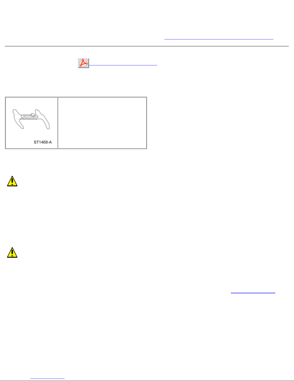
3. Disconnect the parking brake cable at the parking brake lever.
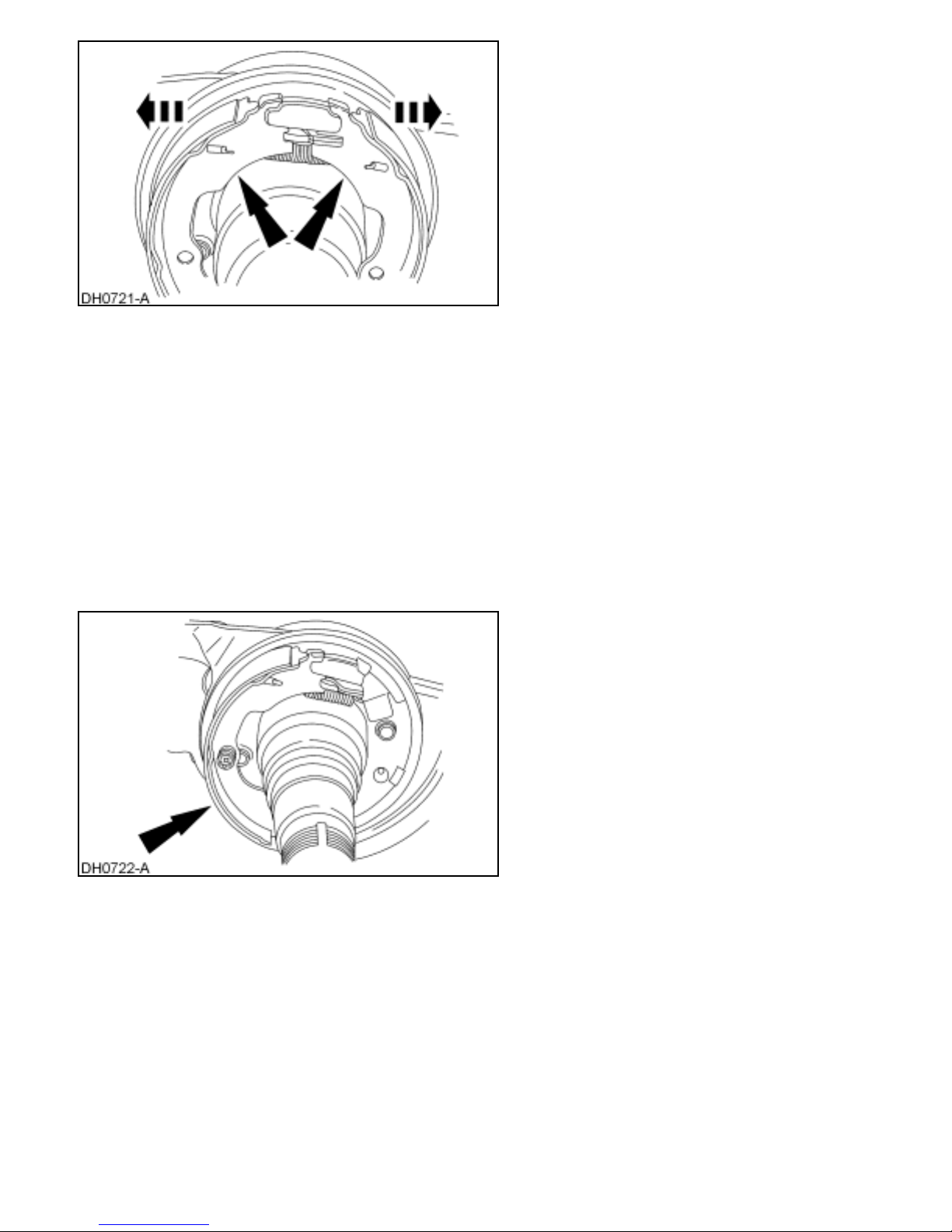
4. Remove the outboard brake shoe retracting spring.
http://www.fordtechservice.dealerconnection.com/pubs/content/~WS4O/~MUS~LEN/19/S4O65007.HTM (2 of 8) [9/12/2009 12:39:36 PM]
Page 3
2004 F-Super Duty 250-550/Excursion Workshop Manual
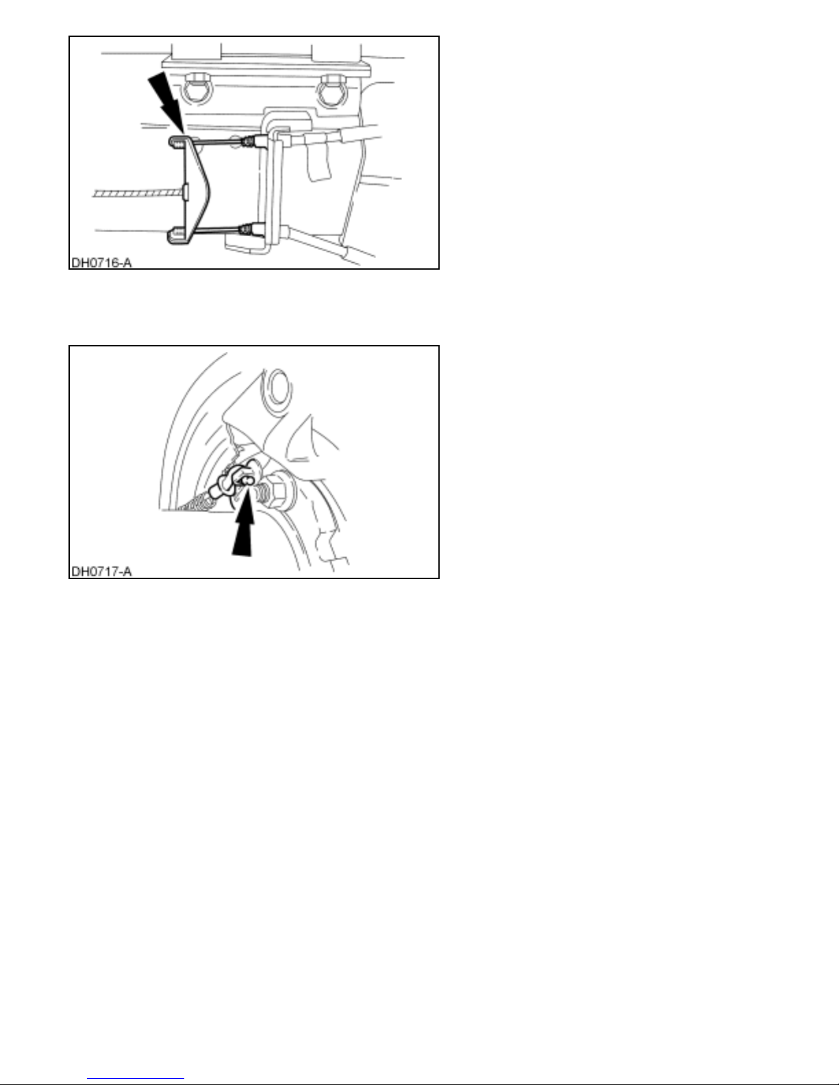
5. Remove the brake shoe adjusting screw spring.
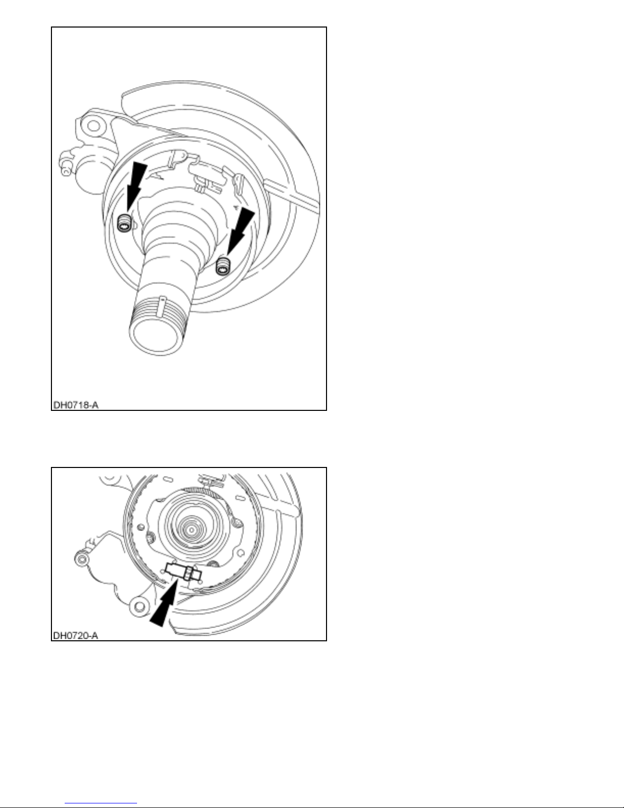
6. Remove the brake shoe hold-down springs.
http://www.fordtechservice.dealerconnection.com/pubs/content/~WS4O/~MUS~LEN/19/S4O65007.HTM (3 of 8) [9/12/2009 12:39:36 PM]
Page 4
2004 F-Super Duty 250-550/Excursion Workshop Manual
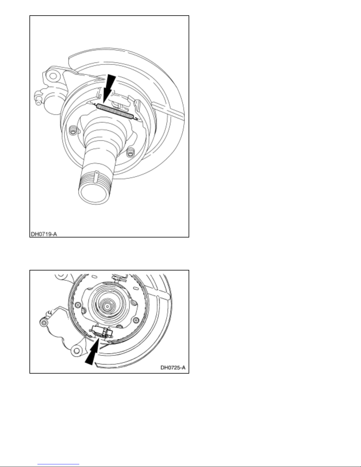
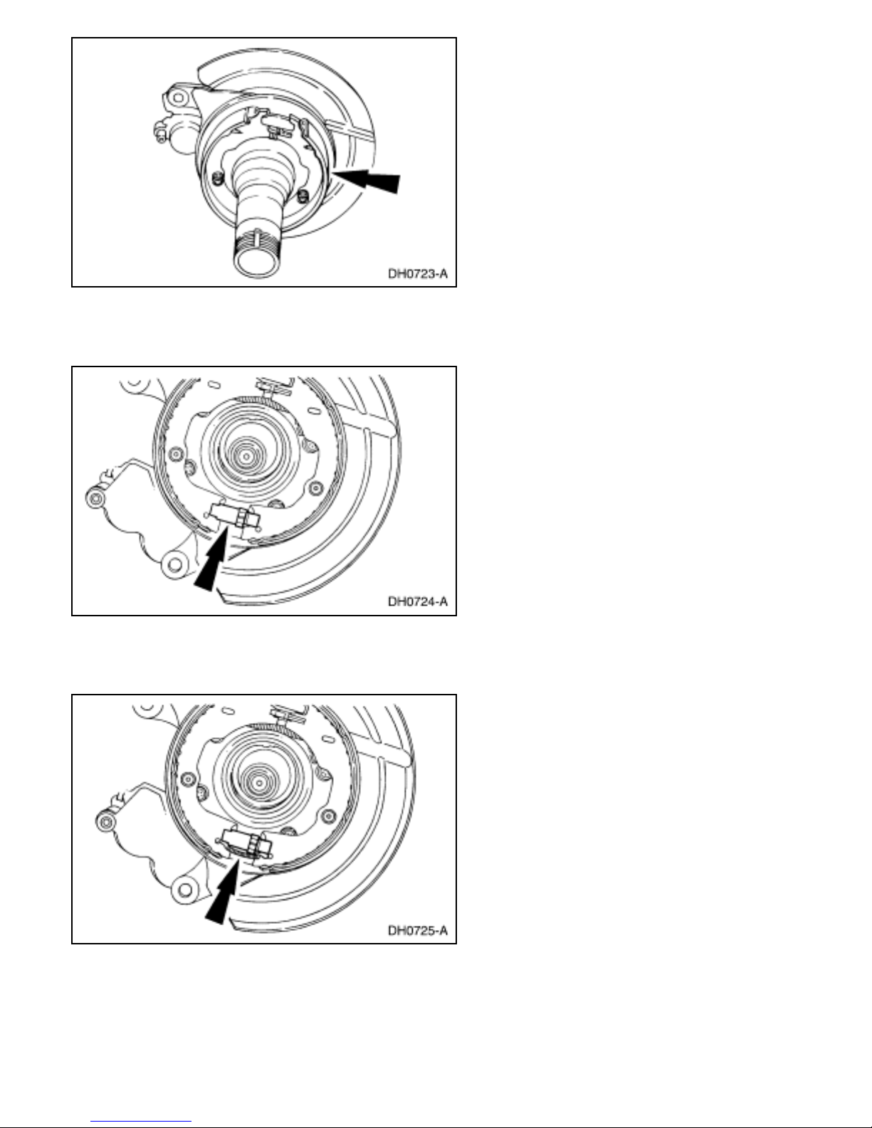
7. Remove the brake adjuster screw (2041).
8. Remove the parking brake shoe and linings (2N712) along with the inboard brake shoe
retracting spring.
http://www.fordtechservice.dealerconnection.com/pubs/content/~WS4O/~MUS~LEN/19/S4O65007.HTM (4 of 8) [9/12/2009 12:39:36 PM]
Page 5
2004 F-Super Duty 250-550/Excursion Workshop Manual
9. Inspect the components for excessive wear or damage and install new as required.
Installation
1. NOTE: Make sure the inboard brake shoe retracting spring is attached to the parking
brake shoe.
Install the LH parking brake shoe and brake shoe hold-down spring, along with the
inboard brake shoe retracting spring.
2. Connect the inboard brake shoe retracting spring to the RH parking brake shoe, and
install the RH parking brake shoe and the brake shoe hold-down spring.
http://www.fordtechservice.dealerconnection.com/pubs/content/~WS4O/~MUS~LEN/19/S4O65007.HTM (5 of 8) [9/12/2009 12:39:36 PM]
Page 6
2004 F-Super Duty 250-550/Excursion Workshop Manual
3. Install the brake adjuster screw.
4. Install the brake shoe adjusting screw spring.
5. NOTE: The outboard brake shoe retracting spring mounts above the inboard brake
shoe retracting spring.
Install the outboard brake shoe retracting spring.
http://www.fordtechservice.dealerconnection.com/pubs/content/~WS4O/~MUS~LEN/19/S4O65007.HTM (6 of 8) [9/12/2009 12:39:36 PM]
Page 7

2004 F-Super Duty 250-550/Excursion Workshop Manual
6. Connect the parking brake cable at the parking brake lever.
7. Connect the rear parking brake cable at the parking brake intermediate cable.
8. Install the rear disc brake rotor. For additional information, refer to Section 206-04.
● Use the Brake Adjusting Gauge to set the rear brake shoe and lining diameter to
0.76 mm (0.030 in.) less than the inside diameter of the drum portion of the rear
disc brake rotor.
http://www.fordtechservice.dealerconnection.com/pubs/content/~WS4O/~MUS~LEN/19/S4O65007.HTM (7 of 8) [9/12/2009 12:39:36 PM]
Page 8

2004 F-Super Duty 250-550/Excursion Workshop Manual
9. Burnish the parking brake shoe and linings.
1. Accelerate the vehicle to 40 km/h (25 mph).
2. Shift the transmission to NEUTRAL.
3. Slowly apply the parking brake control (2780) to approximately one-half to threequarters of its travel.
4. Allow the vehicle to come to a complete stop.
5. Release the parking brake.
http://www.fordtechservice.dealerconnection.com/pubs/content/~WS4O/~MUS~LEN/19/S4O65007.HTM (8 of 8) [9/12/2009 12:39:36 PM]
Page 9

2004 F-Super Duty 250-550/Excursion Workshop Manual
SECTION 205-02F: Wheel Hubs and Bearings —
Full Floating Axle — Ford
2004 F-Super Duty 250-550/
Excursion Workshop Manual
REMOVAL AND INSTALLATION
Procedure revision date: 05/24/2003
Hub
Printable View (353 KB)
Special Tool(s)
2-Jaw Puller
205-D026 (D80L-1002-L) or
Equivalent
Socket, Ford Axle Locknut
205-448
Step Plate
205-D018 (D80L-630-7) or
Equivalent
Material
Item Specification
SAE 75W-140 Synthetic
Rear Axle Lubricant
F1TZ-19580-B
WSL-M2C192-A
Removal
1. Set the parking brake.
2. Loosen the retaining bolts.
http://www.fordtechservice.dealerconnection.com/pubs/content/~WS4O/~MUS~LEN/20/S4O52F06.HTM (1 of 11) [9/12/2009 12:44:54 PM]
Page 10

2004 F-Super Duty 250-550/Excursion Workshop Manual
3. Raise the vehicle to the desired working height, keeping the axle parallel with the floor.
For additional information, refer to
Section 100-02.
4. Release the parking brake.
5. Remove the wheel(s). For additional information, refer to
Section 204-04.
6. Remove the brake caliper and rotor on the single rear wheel axle. For additional
information, refer to
Section 206-04.
7. Remove the retaining bolts and axle shaft.
8. CAUTION: The hub nuts are right-hand thread (right hub) and left-hand
thread (left hub). Each hub nut is stamped RH or LH.
Install the Ford Axle Locknut Socket so that the drive tangs of the tool engage the four
slots in the hub nut.
http://www.fordtechservice.dealerconnection.com/pubs/content/~WS4O/~MUS~LEN/20/S4O52F06.HTM (2 of 11) [9/12/2009 12:44:54 PM]
Page 11

2004 F-Super Duty 250-550/Excursion Workshop Manual
9. CAUTION: Discard the hub nut if the hub nut comes apart during
removal.
CAUTION: Under no circumstances are power tools to be used when
performing these operations.
NOTE: The hub nut will ratchet during this operation.
Remove the hub nut (counterclockwise for right-hand thread; clockwise for left-hand
thread).
http://www.fordtechservice.dealerconnection.com/pubs/content/~WS4O/~MUS~LEN/20/S4O52F06.HTM (3 of 11) [9/12/2009 12:44:54 PM]
Page 12

2004 F-Super Duty 250-550/Excursion Workshop Manual
10. Install the Step Plate.
11. Install the 2-Jaw Puller and loosen the rear hub to the point of removal.
12. CAUTION: Do not drop the outer hub bearing when removing the hub.
Remove the rear hub assembly.
http://www.fordtechservice.dealerconnection.com/pubs/content/~WS4O/~MUS~LEN/20/S4O52F06.HTM (4 of 11) [9/12/2009 12:44:54 PM]
Page 13

2004 F-Super Duty 250-550/Excursion Workshop Manual
13. CAUTION: Install a new hub seal each time the hub assembly is removed.
NOTE: The inner bearing is located behind the hub seal.
Pack each bearing and replace the hub seals. For additional information, refer to
Wheel
Bearings, Wheel Hub Seal and Wheel Bearing Cups in this section.
14.
CAUTION: Use extreme care not to scratch or gouge the seal or bearing
surfaces.
If after hub removal, the hub seal or seal inner sleeve remains on the spindle, remove it
as shown using the Step Plate and the 2-Jaw Puller.
15. Inspect the seal surface and inner shoulder for scratches and damage.
● Remove all scratches, gouges or galling damage with No. 600 or finer crocus
cloth.
http://www.fordtechservice.dealerconnection.com/pubs/content/~WS4O/~MUS~LEN/20/S4O52F06.HTM (5 of 11) [9/12/2009 12:44:54 PM]
Page 14

2004 F-Super Duty 250-550/Excursion Workshop Manual
Installation
1. NOTE: Clean the spindle thoroughly after removing the rear hub.
Coat the spindle with axle lubricant.
2. CAUTION: The hub bearings must be prelubed prior to installation.
Fill the hub cavity with 29.6 ml (1 oz) of axle lubricant.
http://www.fordtechservice.dealerconnection.com/pubs/content/~WS4O/~MUS~LEN/20/S4O52F06.HTM (6 of 11) [9/12/2009 12:44:54 PM]
Page 15

2004 F-Super Duty 250-550/Excursion Workshop Manual
3. CAUTION: Use extreme care not to damage the hub seal by allowing it to
contact the spindle during installation.
NOTE: Coat the spindle and hub seal inside diameter with axle lubricant.
NOTE: Installing the rear hub in this manner causes the outer bearing to act as a pilot
making the installation easier.
Push the rear hub and outer bearing onto the spindle as an assembly.
● Hold the outer bearing seated and use the bearing as a pilot.
4. CAUTION: Install a new hub nut if the hub nut comes apart during
installation.
CAUTION: Make sure the hub nut tab is located in the keyway prior to
thread engagement.
http://www.fordtechservice.dealerconnection.com/pubs/content/~WS4O/~MUS~LEN/20/S4O52F06.HTM (7 of 11) [9/12/2009 12:44:54 PM]
Page 16

2004 F-Super Duty 250-550/Excursion Workshop Manual
Install the hub nut on the spindle.
● Turn the hub nut clockwise for right-hand thread or counterclockwise for left-
hand thread.
5. Position the Ford Axle Locknut Socket on the hub nut.
http://www.fordtechservice.dealerconnection.com/pubs/content/~WS4O/~MUS~LEN/20/S4O52F06.HTM (8 of 11) [9/12/2009 12:44:54 PM]
Page 17

2004 F-Super Duty 250-550/Excursion Workshop Manual
6. CAUTION: Under no circumstances are power tools to be used when
performing these operations.
NOTE: The hub nut will ratchet as torque is applied.
Tighten the hub nut, rotating the rear hub occasionally while tightening.
7. Adjust hub nuts as follows:
● For new bearings, ratchet back five teeth or notches (1/8 turn) on the hub nut.
Five notches must be felt during this operation in order to have performed it
correctly.
● For used bearings, ratchet back seven teeth or notches (1/6 turn) on the hub nut.
Seven notches must be felt during this operation to have performed it correctly.
8. Inspect the axle shaft O-ring seal for cracks, nicks or wear and replace it if required.
http://www.fordtechservice.dealerconnection.com/pubs/content/~WS4O/~MUS~LEN/20/S4O52F06.HTM (9 of 11) [9/12/2009 12:44:54 PM]
Page 18

2004 F-Super Duty 250-550/Excursion Workshop Manual
9. NOTE: Lubricate the O-ring seal with lubricant prior to installation of axle shaft.
Install the axle shaft.
10. NOTE: Coat the threads of the retaining bolts with Stud and Bearing Mount E0AZ19554-BA or equivalent meeting Ford specification WSK-M2G349-A1.
Install and tighten the retaining bolts until they seat.
http://www.fordtechservice.dealerconnection.c.../pubs/content/~WS4O/~MUS~LEN/20/S4O52F06.HTM (10 of 11) [9/12/2009 12:44:54 PM]
Page 19

2004 F-Super Duty 250-550/Excursion Workshop Manual
11. CAUTION: Remember, the last step of this procedure is to tighten the
axle shaft bolts to specification, after the wheel lug nuts have been tightened.
Install the brake rotor and caliper on the single rear wheel axles. For additional
information, refer to
Section 206-04.
12. Install the wheels and tires but do not tighten the lug nuts to specification at this time.
13. Check the axle lubricant level. For additional information, refer to
Section 205-02D.
14. Lower the vehicle.
15. Tighten the wheel lug nuts. For additional information, refer to
Section 204-04.
16. Tighten the axle shaft retaining bolts.
http://www.fordtechservice.dealerconnection.c.../pubs/content/~WS4O/~MUS~LEN/20/S4O52F06.HTM (11 of 11) [9/12/2009 12:44:54 PM]
 Loading...