

Page 1
owner.ford.com ford.ca
2016 F-650/750 Owner’s Manual
2016 F-650/750 Owner’s Manual
June 2015
First Printing
Owner’s Manual
F-650/F-750
Litho in U.S.A.
GC4J 19A321 AA
Page 2

The information contained in this publication was correct at the time of going to print. In the interest of
continuous development, we reserve the right to change specifications, design or equipment at any time
without notice or obligation. No part of this publication may be reproduced, transmitted, stored in a
retrieval system or translated into any language in any form by any means without our written permission.
Errors and omissions excepted.
© Ford Motor Company 2015
All rights reserved.
Part Number: 20150519135424
Page 3

Page 4

Introduction
About This Manual...........................................7
Symbols Glossary...........................................10
Data Recording.................................................12
California Proposition 65.............................13
Perchlorate........................................................13
Ford Credit.........................................................13
Replacement Parts
Recommendation.......................................13
Special Notices................................................14
Mobile Communications
Equipment.....................................................14
Export Unique Options.................................14
Federal Highway Administration
Regulation......................................................14
Entering, Exiting or Climbing on This
Vehicle.............................................................15
Environment
Protecting the Environment........................16
Noise Pollution Control.................................16
Child Safety
General Information.......................................17
Installing Child Restraints............................18
Booster Seats..................................................25
Child Restraint Positioning..........................27
Child Safety Locks.........................................28
Seatbelts
Principle of Operation..................................30
Fastening the Seatbelts..............................30
Seatbelt Height Adjustment......................34
Seatbelt Warning Lamp and Indicator
Chime.............................................................35
Seatbelt Reminder.........................................35
Child Restraint and Seatbelt
Maintenance................................................37
Keys and Remote Controls
General Information on Radio
Frequencies..................................................38
Remote Control..............................................38
Replacing a Lost Key or Remote
Control...........................................................39
Locks
Locking and Unlocking................................40
Security
Passive Anti-Theft System.........................42
Steering Wheel
Adjusting the Steering Wheel...................44
Audio Control..................................................44
Voice Control...................................................45
Cruise Control..................................................45
Information Display Control.......................45
Wipers and Washers
Windshield Wipers........................................46
Windshield Washers.....................................46
Lighting
General Information......................................47
Lighting Control...............................................47
Instrument Lighting Dimmer.....................48
Daytime Running Lamps............................48
Direction Indicators.......................................48
Interior Lamps.................................................49
Windows and Mirrors
Power Windows.............................................50
Exterior Mirrors.................................................51
Interior Mirror...................................................53
Sun Visors.........................................................53
Instrument Cluster
Gauges...............................................................54
1
F650750 (TBC), enUSA, First Printing
Table of Contents
Page 5

Warning Lamps and Indicators................58
Audible Warnings and Indicators..............61
Information Displays
General Information......................................62
Information Messages.................................64
Climate Control
Manual Climate Control..............................70
Hints on Controlling the Interior
Climate............................................................71
Heated Exterior Mirrors.................................72
Seats
Sitting in the Correct Position....................73
Head Restraints...............................................73
Manual Seats...................................................75
Power Seats.....................................................76
Rear Seats.........................................................78
Front Seat Armrest........................................79
Rear Seat Armrest.........................................80
Auxiliary Power Points
Auxiliary Power Points..................................81
Storage Compartments
Overhead Console.........................................83
Starting and Stopping the
Engine
General Information.....................................84
Ignition Switch................................................84
Starting a Gasoline Engine.........................85
Starting a Diesel Engine..............................86
Diesel Particulate Filter................................87
Switching Off the Engine............................88
Engine Idle Shutdown..................................88
Engine Block Heater.....................................88
Fuel and Refueling
Safety Precautions........................................90
Fuel Quality - Gasoline.................................91
Fuel Quality - Diesel......................................92
Running Out of Fuel - 6.8L.........................95
Running Out of Fuel - 6.7L Diesel............95
Selective Catalytic Reduction
System...........................................................95
Refueling - 6.8L............................................100
Refueling - 6.7L Diesel.................................101
Fuel Consumption.......................................102
Emission Control System - 6.8L.............103
Emission Control System - 6.7L
Diesel............................................................105
Fuel Tank Selector Switch..........................112
Transmission
Automatic Transmission.............................113
Power Take-Off...............................................117
Rear Axle
General Information.....................................118
Limited Slip Differential..............................118
Electronic Locking Differential.................118
2-Speed Rear Axle........................................119
Brakes
General Information....................................120
Hints on Driving With Anti-Lock
Brakes...........................................................120
Parking Brake...................................................121
Full Power Brake...........................................124
Air Brakes.........................................................125
Exhaust Brake................................................126
Trailer Brakes..................................................128
Traction Control
Principle of Operation.................................132
Using Traction Control - Vehicles With:
Air Brakes.....................................................132
2
F650750 (TBC), enUSA, First Printing
Table of Contents
Page 6

Using Traction Control - Vehicles With:
Hydraulic Brakes.......................................132
Cruise Control
Principle of Operation.................................134
Using Cruise Control....................................134
Driving Aids
Steering............................................................136
Load Carrying
Load Limit........................................................137
Air Suspension...............................................138
Towing
Towing a Trailer.............................................140
Recommended Towing Weights.............141
Essential Towing Checks...........................142
Transporting the Vehicle............................143
Fifth Wheel Operation................................144
Driving Hints
Breaking-In.....................................................146
General Driving Points................................146
Economical Driving......................................147
Cold Weather Precautions........................148
Driving Through Water...............................150
Roadside Emergencies
Roadside Assistance....................................151
Hazard Warning Flashers...........................152
Fuel Shutoff....................................................152
Jump Starting the Vehicle.........................153
Customer Assistance
Getting the Services You Need...............156
In California (U.S. Only)..............................157
The Better Business Bureau (BBB) Auto
Line Program (U.S. Only)......................158
Utilizing the Mediation/Arbitration
Program (Canada Only)........................158
Getting Assistance Outside the U.S. and
Canada.........................................................159
Ordering Additional Owner's
Literature.....................................................160
Reporting Safety Defects (U.S.
Only).............................................................160
Reporting Safety Defects (Canada
Only)..............................................................161
Fuses
Fuse Specification Chart...........................162
Changing a Fuse...........................................170
Vehicle Inspection Guide
Vehicle Inspection Information.................171
Maintenance
General Information....................................180
Opening and Closing the Hood................181
Under Hood Overview - 6.8L...................183
Under Hood Overview - 6.7L Diesel......184
Engine Oil Dipstick - 6.8L..........................185
Engine Oil Dipstick - 6.7L Diesel.............185
Engine Oil Check - 6.8L..............................185
Engine Oil Check - 6.7L Diesel.................186
Changing the Engine Oil and Oil
Filter..............................................................188
Changing the Coalescer Filter
Element.......................................................189
Oil Change Indicator Reset.......................190
Engine Coolant Check - 6.8L...................190
Engine Coolant Check - 6.7L Diesel.......195
Automatic Transmission Fluid
Check...........................................................200
Brake Fluid Check.........................................201
Power Steering Fluid Check.....................202
Washer Fluid Check....................................202
Draining the Fuel Filter Water Trap - 6.7L
Diesel...........................................................203
3
F650750 (TBC), enUSA, First Printing
Table of Contents
Page 7

Fuel Filter - 6.8L...........................................204
Changing the 12V Battery.........................204
Checking the Wiper Blades.....................206
Changing the Wiper Blades....................206
Adjusting the Headlamps........................206
Removing a Headlamp.............................208
Changing a Bulb..........................................208
Bulb Specification Chart..........................209
Changing the Engine Air Filter - 6.8L.....210
Changing the Engine Air Filter - 6.7L
Diesel..............................................................211
Changing the Engine-Mounted and
Diesel Fuel Conditioner Module Fuel
Filters - 6.7L Diesel...................................215
Electrical System Inspection....................217
Air Induction System Inspection.............217
Exhaust System Inspection......................218
Brake System Inspection...........................218
Axle Inspection..............................................221
Steering System Inspection.....................222
Suspension System Inspection..............222
Frame and Tow Hook Inspection...........223
Rear Axle Fluid Check.................................223
Spring U-Bolt Check...................................223
Vehicle Care
General Information...................................225
Cleaning Products.......................................225
Cleaning the Exterior..................................225
Waxing.............................................................226
Cleaning the Engine....................................226
Cleaning the Windows and Wiper
Blades...........................................................227
Cleaning the Interior....................................227
Cleaning the Instrument Panel and
Instrument Cluster Lens.......................228
Repairing Minor Paint Damage..............228
Cleaning the Alloy Wheels.......................229
Vehicle Storage.............................................229
Wheels and Tires
Tire Care..........................................................232
Using Snow Chains.....................................246
Changing a Road Wheel............................247
Technical Specifications...........................249
Capacities and Specific-
ations
Engine Specifications - 6.8L.....................251
Engine Specifications - 6.7L Diesel........251
Motorcraft Parts - 6.8L..............................252
Motorcraft Parts - 6.7L Diesel.................253
Vehicle Identification Number................254
Vehicle Certification Label.......................255
Transmission Code Designation............255
Capacities and Specifications -
6.8L...............................................................256
Capacities and Specifications - 6.7L
Diesel............................................................261
Audio System
General Information...................................270
Audio Unit - Vehicles With: AM/FM........271
Audio Unit - Vehicles With: AM/FM/CD/
SYNC.............................................................272
Satellite Radio...............................................275
Audio Input Jack............................................277
USB Port..........................................................277
SYNC™
General Information...................................279
Using Voice Recognition............................281
Using SYNC™ With Your Phone............283
Using SYNC™ With Your Media
Player...........................................................295
SYNC™ Troubleshooting.........................304
Accessories
Auxiliary Switches........................................310
4
F650750 (TBC), enUSA, First Printing
Table of Contents
Page 8

Extended Service Plan
(ESP)
Extended Service Plan (ESP)..................312
Scheduled Maintenance
General Maintenance Information.........314
Normal Scheduled Maintenance............321
Special Operating Conditions Scheduled
Maintenance.............................................326
Scheduled Maintenance Record...........335
Appendices
End User License Agreement.................345
5
F650750 (TBC), enUSA, First Printing
Table of Contents
Page 9

6
F650750 (TBC), enUSA, First Printing
Page 10

ABOUT THIS MANUAL
Thank you for choosing Ford. We
recommend that you take some time to
get to know your vehicle by reading this
manual. The more that you know about
your vehicle, the greater the safety and
pleasure you will get from driving it.
WARNING
Driving while distracted can result in
loss of vehicle control, crash and
injury. We strongly recommend that
you use extreme caution when using any
device that may take your focus off the
road. Your primary responsibility is the safe
operation of your vehicle. We recommend
against the use of any hand-held device
while driving and encourage the use of
voice-operated systems when possible.
Make sure you are aware of all applicable
local laws that may affect the use of
electronic devices while driving.
Note: Always use and operate your vehicle
in line with all applicable laws and
regulations.
Note: Pass on this manual when selling
your vehicle. It is an integral part of your
vehicle.
Note: Your vehicle’s powertrain control
systems can detect and store information
about vehicle modifications that increase
horsepower and torque output such as
whether or not performance-enhancing
powertrain components commonly referred
to as performance chips have been used.
This information will stay in the system’s
memory and cannot be erased even if the
modification is removed. Ford Motor
Company, Ford of Canada, Ford of Mexico
and service or repair facilities can retrieve
this information when servicing your vehicle.
Ford Motor Company may use this
information to determine if your warranty
covers any needed repairs.
Note: Some aftermarket products may
cause severe engine/transmission and/or
exhaust system damage; refer to your
warranty information for more information.
Your new diesel engine will feel, drive and
function somewhat differently than a
gasoline engine. Therefore it is very
important that you read and thoroughly
familiarize yourself and others operating
the vehicle with this guide. There is a
special procedure for turning off the diesel
engine. See Starting a Diesel Engine
(page 86). It is important to read and
understand this material in order to
maintain the best service life for your
engine.
Ford may discontinue models or change
specifications without any notice and
without incurring obligations.
Note: Either Ford Motor Company or an
authorized Ford dealer may have originally
sold this incomplete vehicle to a vehicle
modifier who upfitted it. As a result, some
of the options and features on this vehicle
may differ from what we describe in this
manual.
This manual may qualify the location of a
component as left-hand side or right-hand
side. The side is determined when facing
forward in the seat.
7
F650750 (TBC), enUSA, First Printing
Introduction
Page 11
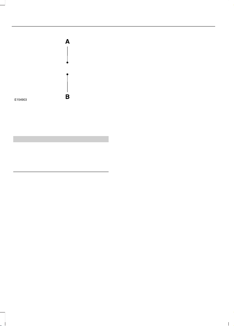
E154903
Right-hand side.A
Left-hand side.B
Warnings
WARNING
Throughout this guide, you will find
warnings identified by the warning
symbol. Warnings remind you to be
especially careful to reduce the risk of
personal injury.
Diesel Engine Information
The diesel engine fuel system is a
pressurized two-stage filtration system
and consists of:
• A frame-mounted Fuel and Water
Separator primary filter with an electric
fuel pump and water drain
• An engine-mounted secondary fuel
filter
• A fuel injector for each cylinder (8
total)
• A high-pressure fuel pump
• A high-pressure fuel rail for each
cylinder bank (2 total)
• Numerous high-pressure pipes from
the high-pressure pump to the rails,
and rails to the injectors
The fuel and water separator removes
both water and impurities from the fuel.
The engine-mounted filter filters finer
impurities from the diesel fuel. The
engine-mounted fuel filter and the
frame-mounted fuel filter should be
changed at the recommended service
interval or when indicated by the
information display LOW FUEL PRESSURE
message. See Scheduled Maintenance
(page 314).
The fuel and water separator should be
drained at regular intervals (recommended
at every oil change) or when indicated by
the information display and water in fuel
indicator light. See Fuel Quality (page
92).
Proper fuel filter maintenance and prompt
water draining when the water in fuel light
illuminates is essential to prevent injection
equipment damage. Ignoring the water in
fuel light or the information display
message WATER IN FUEL DRAIN FILTER
can cause your vehicle to go into a reduced
power mode.
A frame-mounted electric fuel pump
located inside the fuel and water separator
draws fuel from the fuel tank to provide
pressurized fuel to the engine. The fuel
pump contains a pressure relief valve for
overpressure protection in the event of
restricted flow.
The fuel injection system is controlled
through the powertrain control module.
Engine Protection Mode
Ford diesel engines are equipped with
engine protection and emission control
systems. These systems monitor critical
temperatures and pressures, and modify
engine operation accordingly. These
modified engine performance
characteristics are normal.
8
F650750 (TBC), enUSA, First Printing
Introduction
Page 12

If these modified engine performance
characteristics persist for an extended
period and either the service engine soon
or powertrain malfunction, reduced power,
electronic throttle control light is
illuminated, have the system checked by
an authorized dealer.
Service engine soon
Powertrain malfunction, reduced
power, electronic throttle control
Diesel Lubrication System
It is important to change the engine oil at
the recommended service intervals or
when indicated by the information display
to maintain oil viscosity. Extending the oil
and filter change interval beyond the
recommended interval can negatively
affect engine performance, fuel economy
and engine life. See Engine Oil Check
(page 186).
Engine and secondary cooling system
The cooling system contains a primary
cooling loop to cool the engine and a
secondary cooling loop to cool the
transmission, charge air, and fuel. The
coolant serves three primary purposes: to
provide heat transfer, freeze point
protection, and corrosion protection using
additives.
Vehicles with diesel engines typically are
used to carry heavy loads and accumulate
mileage rapidly. These two factors may
cause the additives in the coolant to wear
out in a shorter time. You can find more
information about coolant additives and
coolant change intervals in the coolant
chapter. See General Maintenance
Information (page 314). Operating the
engine with insufficient coolant or coolant
additive can cause severe engine damage.
Selective catalytic reduction system
Your vehicle is equipped with a selective
catalytic reduction system designed to
reduce emission levels of nitrogen oxides
from the exhaust of your diesel engine. This
system relies on the use of Diesel Exhaust
Fluid (DEF) that you must replenish at
certain intervals. Failure to maintain proper
DEF levels or if the DEF becomes
contaminated will result in vehicle speed
limitations or result in your vehicle entering
an idle-only mode. See Selective
Catalytic Reduction System (page 95).
Minor Troubleshooting Guide
If the engine won’t crank
WARNING
Battery posts, terminals and related
accessories contain lead and lead
compounds. Wash hands after
handling.
Turn on the headlights. If the lights are dim,
do not go on at all or when the ignition is
turned to the start position, the lights
become dim or go out, the battery
connections may be loose or corroded, or
the battery may be discharged. If there is
a clicking or stuttering sound coming from
the engine compartment when you turn
the key to the start position, this may also
indicate a loose or corroded battery
connection.
Check the battery connections at the
battery posts, cable connection to the
engine grounding point and at the starter
connection.
If you suspect a discharged battery, have
it checked and corrected.
9
F650750 (TBC), enUSA, First Printing
Introduction
Page 13

• The gearshift lever must be in P (Park)
or N (Neutral) in order for the starter
to operate.
• Try operating the starter switch several
times. This operation may clean
potentially corroded contacts or make
the switch temporarily operable until
you can reach the dealer.
• If all electrical connections are tight
and you need assistance to start, See
Jump Starting the Vehicle (page 153).
If engine cranks but won’t start
Prolonged starter cranking (in excess of 10
seconds) could cause damage to the
starter motor or the high-pressure fuel
pump.
• Check the fuel gauge. You may be out
of fuel. If the gauge shows that there
is fuel in the tank, the trouble may be
in the electrical system or the fuel
system. If equipped with an auxiliary
tank, be sure that the tank control
switch is set for the tank with fuel and
not on an empty tank.
• Leaving your ignition key turned to on
for over two minutes without starting
may make starting difficult because
the glow plugs will cease activation.
Reset the system by turning the ignition
key to off and then back to on again.
Note: If the system is out of fuel and the
engine will not start, do not continue
cranking the engine. Continued cranking can
damage the high-pressure fuel pump.
If the engine runs hot
The following could cause the engine to
overheat:
• Lack of coolant
• Dirty cooling system.
• Plugged radiator fins, A/C condenser
and/or oil cooler
• Malfunctioning fan drive
• Driving with frozen coolant
• Sticking thermostat
• Overloading or pulling heavy trailers
during hot weather
• Grill or radiator air blockage
• Slipping or missing drive belt
• Plugged or very dirty air filter
If fuses burn out
WARNING
Replacement fuses and circuit
breakers must always be the same
rating as the original equipment
shown. Never replace a fuse or circuit
breaker with one of a higher rating. Higher
rated fuses or circuit breakers could allow
circuit overloading in the event of a circuit
malfunction, resulting in severe vehicle
damage or personal injury due to fire.
Burned-out or blown fuses usually indicate
an electrical short-circuit, although a fuse
may occasionally burn out from vibration.
Insert a second fuse. If this fuse
immediately burns out and you cannot
locate the cause, return your vehicle to
your dealer for a circuit check. See
Changing a Fuse (page 170).
Selective catalytic reduction system
speed limit and Idle-only modes
If the vehicle’s speed is limited or in an
idle-only mode, the selective catalytic
reduction system may be limiting the
vehicle’s functions due to low or
contaminated DEF. Check the DEF. See
Selective Catalytic Reduction System
(page 95).
SYMBOLS GLOSSARY
These are some of the symbols you may
see on your vehicle.
10
F650750 (TBC), enUSA, First Printing
Introduction
Page 14
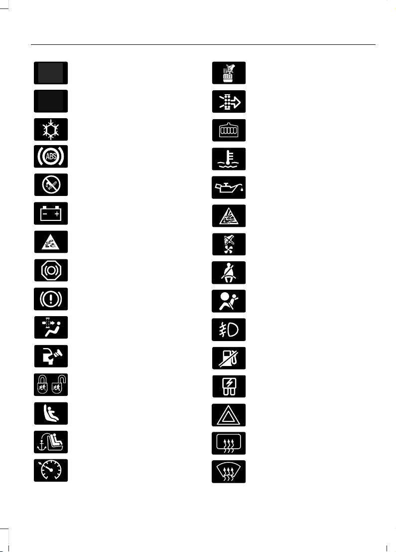
Safety alert
See Owner's Manual
Air conditioning system
Anti-lock braking system
Avoid smoking, flames or sparks
Battery
Battery acid
Brake fluid - non petroleum
based
Brake system
Cabin air filter
Check fuel cap
Child safety door lock or unlock
Child seat lower anchor
Child seat tether anchor
E71340
Cruise control
Do not open when hot
Engine air filter
Engine coolant
Engine coolant temperature
Engine oil
Explosive gas
Fan warning
Fasten seatbelt
Front airbag
Front fog lamps
Fuel pump reset
Fuse compartment
Hazard warning flashers
Heated rear window
Heated windshield
11
F650750 (TBC), enUSA, First Printing
Introduction
Page 15
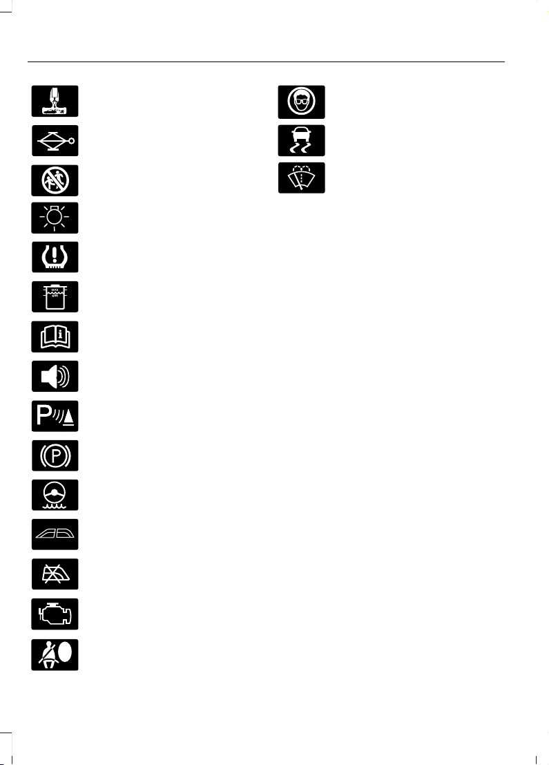
Interior luggage compartment
release
Jack
Keep out of reach of children
Lighting control
Low tire pressure warning
Maintain correct fluid level
Note operating instructions
Panic alarm
E139213
Parking aid
Parking brake
Power steering fluid
Power windows front/rear
Power window lockout
Service engine soon
Side airbag
Shield the eyes
E138639
Stability control
Windshield wash and wipe
DATA RECORDING
Service Data Recording
Service data recorders in your vehicle are
capable of collecting and storing
diagnostic information about your vehicle.
This potentially includes information about
the performance or status of various
systems and modules in the vehicle, such
as engine, throttle, steering or brake
systems. In order to properly diagnose and
service your vehicle, Ford Motor Company,
Ford of Canada, and service and repair
facilities may access or share among them
vehicle diagnostic information received
through a direct connection to your vehicle
when diagnosing or servicing your vehicle.
Additionally, when your vehicle is in for
service or repair, Ford Motor Company,
Ford of Canada, and service and repair
facilities may access or share among them
data for vehicle improvement purposes.
For the United States only (if equipped),
if you choose to use the SYNC Vehicle
Health Report, you consent that certain
diagnostic information may also be
accessed electronically by Ford Motor
Company and Ford authorized service
facilities, and that the diagnostic
information may be used for any purpose.
See SYNC™ (page 279).
12
F650750 (TBC), enUSA, First Printing
Introduction
Page 16
CALIFORNIA PROPOSITION 65
WARNING
Some constituents of engine
exhaust, certain vehicle components,
certain fluids contained in vehicles
and certain products of component wear
contain or emit chemicals known to the
State of California to cause cancer and
birth defects or other reproductive harm.
PERCHLORATE
Certain components in your vehicle such
as airbag modules, safety belt
pretensioners and remote control batteries
may contain perchlorate material. Special
handling may apply for service or vehicle
end of life disposal.
For more information visit:
Web Address
www.dtsc.ca.gov/hazardouswaste/
perchlorate
FORD CREDIT
(U.S. Only)
Ford Credit offers a full range of financing
and lease plans to help you acquire your
vehicle. If you have financed or leased your
vehicle through Ford Credit, thank you for
your business.
For your convenience we offer a number
of ways to contact us, as well as to help
manage your account.
Phone: 1-800-727-7000
For more information regarding Ford Credit,
as well as to access Account Manager,
please go to www.fordcredit.com.
REPLACEMENT PARTS RECOMMENDATION
Your vehicle has been built to the highest
standards using quality parts. We
recommend that you demand the use of
genuine Ford and Motorcraft parts
whenever your vehicle requires scheduled
maintenance or repair. You can clearly
identify genuine Ford and Motorcraft parts
by looking for the Ford, FoMoCo or
Motorcraft branding on the parts or their
packaging.
Scheduled Maintenance and
Mechanical Repairs
One of the best ways for you to make sure
that your vehicle provides years of service
is to have it maintained in line with our
recommendations using parts that
conform to the specifications detailed in
this Owner’s Manual. Genuine Ford and
Motorcraft parts meet or exceed these
specifications.
Collision Repairs
We hope that you never experience a
collision, but accidents do happen. Genuine
Ford replacement collision parts meet our
stringent requirements for fit, finish,
structural integrity, corrosion protection
and dent resistance. During vehicle
development we validate these parts
deliver the intended level of protection as
a whole system. A great way to know for
sure you are getting this level of protection
is to use genuine Ford replacement
collision parts.
13
F650750 (TBC), enUSA, First Printing
Introduction
Page 17

Warranty on Replacement Parts
Genuine Ford and Motorcraft replacement
parts are the only replacement parts that
benefit from a Ford Warranty. Damage
caused to your vehicle as a result of the
failure of non-Ford parts may not be
covered by the Ford Warranty. For
additional information, refer to the terms
and conditions of the Ford Warranty.
SPECIAL NOTICES
New Vehicle Limited Warranty
For a detailed description of what is
covered and what is not covered by your
vehicle's New Vehicle Limited Warranty,
see the warranty information that is
provided to you along with your owner's
manual.
Special Instructions
For your added safety, your vehicle is fitted
with sophisticated electronic controls.
MOBILE COMMUNICATIONS EQUIPMENT
Using mobile communications equipment
is becoming increasingly important in the
conduct of business and personal affairs.
However, you must not compromise your
own or others’ safety when using such
equipment. Mobile communications can
enhance personal safety and security when
appropriately used, particularly in
emergency situations. Safety must be
paramount when using mobile
communications equipment to avoid
negating these benefits. Mobile
communication equipment includes, but
is not limited to, cellular phones, pagers,
portable email devices, text messaging
devices and portable two-way radios.
WARNING
Driving while distracted can result in
loss of vehicle control, crash and
injury. We strongly recommend that
you use extreme caution when using any
device that may take your focus off the
road. Your primary responsibility is the safe
operation of your vehicle. We recommend
against the use of any hand-held device
while driving and encourage the use of
voice-operated systems when possible.
Make sure you are aware of all applicable
local laws that may affect the use of
electronic devices while driving.
EXPORT UNIQUE OPTIONS
For your particular global region, your
vehicle may be equipped with features and
options that are different from the features
and options that are described in this
Owner’s Manual. A market unique
supplement may be supplied that
complements this book. By referring to the
market unique supplement, if provided,
you can properly identify those features,
recommendations and specifications that
are unique to your vehicle. This Owner’s
Manual is written primarily for the U.S. and
Canadian Markets. Features or equipment
listed as standard may be different on units
built for Export. Refer to this Owner’s
Manual for all other required
information and warnings.
FEDERAL HIGHWAY ADMINISTRATION REGULATION
Regulations such as those issued by the
Federal Highway Administration or issued
pursuant to the Occupational Safety and
Health Act (OSHA), and state and local
laws and regulations may require
additional equipment for the way you
14
F650750 (TBC), enUSA, First Printing
Introduction
Page 18

intend to use the vehicle. It is the
responsibility of the registered owner to
determine the applicability of such laws
and regulations to your intended use for
the vehicle, and to arrange for the
installation of required equipment. Your
dealer has information about the
availability of equipment which may be
ordered for your vehicle.
ENTERING, EXITING OR CLIMBING ON THIS VEHICLE
WARNING
Do not carry items while entering,
exiting or climbing. Make sure you
keep a firm grip. Always FACE the
VEHICLE STEP and HANDLE SYSTEM
while climbing up and down. Do not climb
behind the cab unless you have three point
contact with a step and handle system at
all times.
You must be careful and deliberate to
minimize the possibility of personal injury
from a slip and fall when entering, exiting
or climbing on this vehicle. Always use the
steps and assist handles before climbing.
Do not skip any steps or assist handles.
Use three point contact at all times with
at least two feet and one hand or two
hands and one foot firmly placed during
all phases of entering, exiting or climbing.
Always keep your shoe soles and hands
clean. Keep the steps and assist handles
free of snow, ice, oil, grease, substances or
debris. Be sure to use extra care in bad
weather. Avoid wearing thick gloves.
Always perform trailer hook-up while
standing on the ground.
15
F650750 (TBC), enUSA, First Printing
Introduction
Page 19

PROTECTING THE ENVIRONMENT
You must play your part in protecting the
environment. Correct vehicle usage and
the authorized disposal of waste, cleaning
and lubrication materials are significant
steps toward this aim.
NOISE POLLUTION CONTROL
In order to keep to the federal exterior
noise regulations, your vehicle may be
equipped with noise emission items.
Depending on your vehicle configuration,
it may have all or some of the following
items:
Air Intake System
Inspect the air cleaner. Do not alter its
location. Do not alter inlet and outlet
piping.
Body
Inspect wheel well splash shields, cab
shields and under hood insulation for
deterioration, dislocation and orientation.
Cooling System
• Inspect the fan for blade damage. If
you find any damage, replace with the
recommended parts. Inspect for
fan-to-shroud interference and any
damage to shroud, such as cracks and
holes.
• Do not change fan ratio or alter fan
spacer dimensions and positions.
• Inspect fan clutch for proper operation.
Make sure the fan is disengaged when
cooling of the engine is not required.
• Inspect radiator shutters (if equipped)
for proper operation. The shutters
should be open during normal
operating temperatures.
Engine
Valve covers and block covers damp-out
engine mechanical noise. If they need
replacing, make sure to replace them with
the recommended parts. Check for
mechanical isolations.
Transmission Enclosure
Inspect for cracks, holes and tears. Clean
any deposits, such as oil, dirt and stones.
Exhaust System
• Inspect for leaks at various joint
connections and loose clamps.
• Perform a visual inspection for cracks
or holes in the muffler and tail pipe.
• Always use the recommended
replacement parts.
• Do not change the tail pipe elbow or
offset tail pipe orientation from the
standard position as originally received.
• To avoid abnormal changes in vehicle
sound levels, it is necessary for the
owner to perform inspections and
necessary maintenance at specified
intervals. See Scheduled
Maintenance (page 314).
16
F650750 (TBC), enUSA, First Printing
Environment
Page 20

GENERAL INFORMATION
See the following sections for directions
on how to properly use safety restraints
for children.
WARNINGS
Always make sure your child is
secured properly in a device that is
appropriate for their height, age and
weight. Child safety restraints must be
bought separately from your vehicle.
Failure to follow these instructions and
guidelines may result in an increased risk
of serious injury or death to your child.
All children are shaped differently.
The recommendations for safety
restraints are based on probable
child height, age and weight thresholds
from National Highway Traffic Safety
Administration and other safety
organizations, or are the minimum
requirements of law. Ford recommends
checking with a NHTSA Certified Child
Passenger Safety Technician (CPST) and
consult your pediatrician to make sure your
child seat is appropriate for your child, and
WARNINGS
is compatible with and properly installed
in your vehicle. To locate a child seat fitting
station and CPST, contact the NHTSA toll
free at 1-888-327-4236 or go to
http://www.nhtsa.dot.gov. In Canada,
check with your local St. John Ambulance
office for referral to a CPST or for further
information, contact your provincial
ministry of transportation, locate your local
St. John Ambulance office by searching for
St. John Ambulance on the internet, or
Transport Canada at 1-800-333-0371
(http://www.tc.gc.ca). Failure to properly
restrain children in safety seats made
especially for their height, age, and weight
may result in an increased risk of serious
injury or death to your child.
Do not leave children or animals
unattended in the vehicle. On hot
days, the temperature in the trunk or
vehicle interior can rise very quickly.
Exposure of people or animals to these
high temperatures for even a short time
can cause death or serious heat-related
injuries, including brain damage. Small
children are particularly at risk.
17
F650750 (TBC), enUSA, First Printing
Child Safety
Page 21

Recommendations for Safety Restraints for Children
Recommended restraint
type
Child size, height, weight, or ageChild
Use a child safety seat
(sometimes called an
infant carrier, convertible
seat, or toddler seat).
Children weighing 40 lb (18 kg) or less
(generally age four or younger).
Infants or
toddlers
Use a belt-positioning
booster seat.
Children who have outgrown or no longer
properly fit in a child safety seat (gener-
ally children who are less than 4 ft. 9 in.
(1.45 m) tall, are greater than age four
and less than age 12, and between 40 lb
(18 kg) and 80 lb (36 kg) and upward to
100 lb (45 kg) if recommended by your
child restraint manufacturer).
Small children
Use a vehicle safety belt
having the lap belt snug
and low across the hips,
shoulder belt centered
across the shoulder and
chest, and seat back
upright.
Children who have outgrown or no longer
properly fit in a belt-positioning booster
seat (generally children who are at least
4 ft. 9 in. (1.45 m) tall or greater than 80
lb (36 kg) or 100 lb (45 kg) if recom-
mended by child restraint manufacturer).
Larger children
• You are required by law to properly use
safety seats for infants and toddlers in
the United States and Canada.
• Many states and provinces require that
small children use approved booster
seats until they reach age eight, a
height of 4 feet 9 inches (1.45 meters)
tall, or 80 pounds (36 kilograms).
Check your local and state or provincial
laws for specific requirements about
the safety of children in your vehicle.
• When possible, always properly
restrain children 12 years of age and
under in a rear seating position of your
vehicle. Accident statistics suggest that
children are safer when properly
restrained in the rear seating positions
than in a front seating position.
INSTALLING CHILD RESTRAINTS
Child Seats
E142594
18
F650750 (TBC), enUSA, First Printing
Child Safety
Page 22
Use a child safety seat (sometimes called
an infant carrier, convertible seat, or
toddler seat) for infants, toddlers, or
children weighing 40 pounds (18
kilograms) or less (generally age four or
younger).
Using Lap and Shoulder Belts
WARNINGS
Children 12 and under should be
properly restrained in the rear seat
whenever possible.
Depending on where you secure a
child restraint, and depending on the
child restraint design, you may block
access to certain safety belt buckle
assemblies and LATCH lower anchors,
rendering those features potentially
unusable. To avoid risk of injury, occupants
should only use seating positions where
they are able to be properly restrained.
When installing a child safety seat with
combination lap and shoulder belts:
• Use the correct safety belt buckle for
that seating position.
• Insert the belt tongue into the proper
buckle until you hear a snap and feel it
latch. Make sure the tongue is securely
fastened in the buckle.
• Keep the buckle release button
pointing up and away from the safety
seat, with the tongue between the child
seat and the release button, to prevent
accidental unbuckling.
• Place the vehicle seat upon which the
child seat will be installed in the upright
position.
• This vehicle does not require the use
of a locking clip.
Perform the following steps when
installing the child seat with combination
lap and shoulder belts:
Note: Although the child seat illustrated is
a forward facing child seat, the steps are
the same for installing a rear facing child
seat.
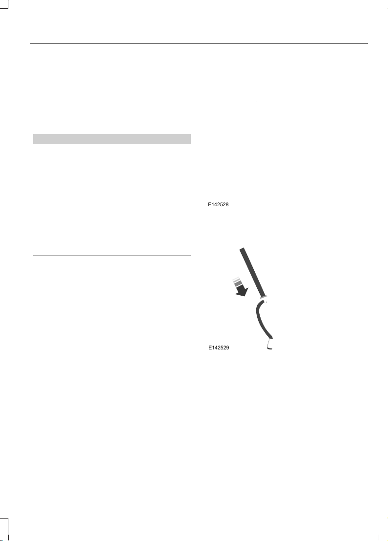
E142528
1. Position the child safety seat in a seat
with a combination lap and shoulder
belt.
E142529
2. Pull down on the shoulder belt and
then grasp the shoulder belt and lap
belt together.
19
F650750 (TBC), enUSA, First Printing
Child Safety
Page 23
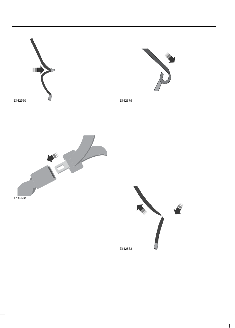
E142530
3. While holding the shoulder and lap belt
portions together, route the tongue
through the child seat according to the
child seat manufacturer's instructions.
Be sure the belt webbing is not twisted.
E142531
4. Insert the belt tongue into the proper
buckle (the buckle closest to the
direction the tongue is coming from)
for that seating position until you hear
a snap and feel the latch engage. Make
sure the tongue is latched securely by
pulling on it.
E142875
5. To put the retractor in the automatic
locking mode, grasp the shoulder
portion of the belt and pull downward
until all of the belt is pulled out.
6. Allow the belt to retract to remove
slack. The belt will click as it retracts
to indicate it is in the automatic locking
mode.
7. Try to pull the belt out of the retractor
to make sure the retractor is in the
automatic locking mode (you should
not be able to pull more belt out). If the
retractor is not locked, unbuckle the
belt and repeat Steps 5 and 6.
E142533
8. Remove remaining slack from the belt.
Force the seat down with extra weight,
for example, by pressing down or
kneeling on the child restraint while
pulling up on the shoulder belt in order
to force slack from the belt. This is
20
F650750 (TBC), enUSA, First Printing
Child Safety
Page 24
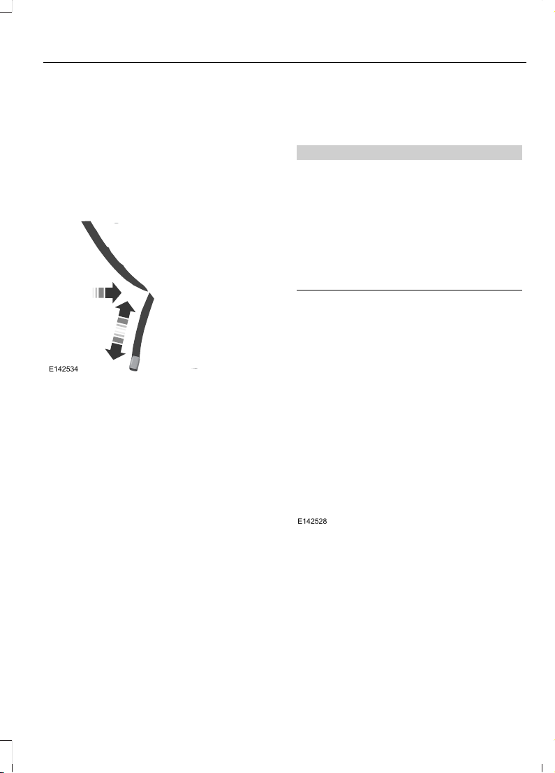
necessary to remove the remaining
slack that will exist once the extra
weight of the child is added to the child
restraint. It also helps to achieve the
proper snugness of the child seat to
your vehicle. Sometimes, a slight lean
toward the buckle will help to remove
remaining slack from the belt.
9. Attach the tether strap (if the child seat
is equipped).
E142534
10. Before placing the child in the seat,
forcibly move the seat forward and
back to make sure the seat is securely
held in place.
To check this, grab the seat at the belt path
and attempt to move it side to side and
forward and back. There should be no
more than 1 inch (2.5 centimeters) of
movement for proper installation.
Ford recommends checking with a NHTSA
Certified Child Passenger Safety
Technician to make certain the child
restraint is properly installed. In Canada,
check with your local St. John Ambulance
office for referral to a Certified Passenger
Seat Technician.
Using Cinch Tongue Lap and
Shoulder Belts (All Front Center,
Super Cab and Crew Cab Rear
Center Positions)
WARNINGS
Airbags can kill or injure a child in a
child seat. If you must use a
forward-facing child seat in the front
seat, move seat all the way back.
Rear facing child seats should never
be placed in front of an active airbag.
Always use both lap and shoulder
safety belt in the Regular Cab center
seating position if applicable.
The belt webbing below the tongue is the
lap portion of the combination lap and
shoulder belt, and the belt webbing above
the tongue is the shoulder belt portion of
the combination lap and shoulder belt.
E142528
1. Position the child safety seat in the
front center seat.
21
F650750 (TBC), enUSA, First Printing
Child Safety
Page 25
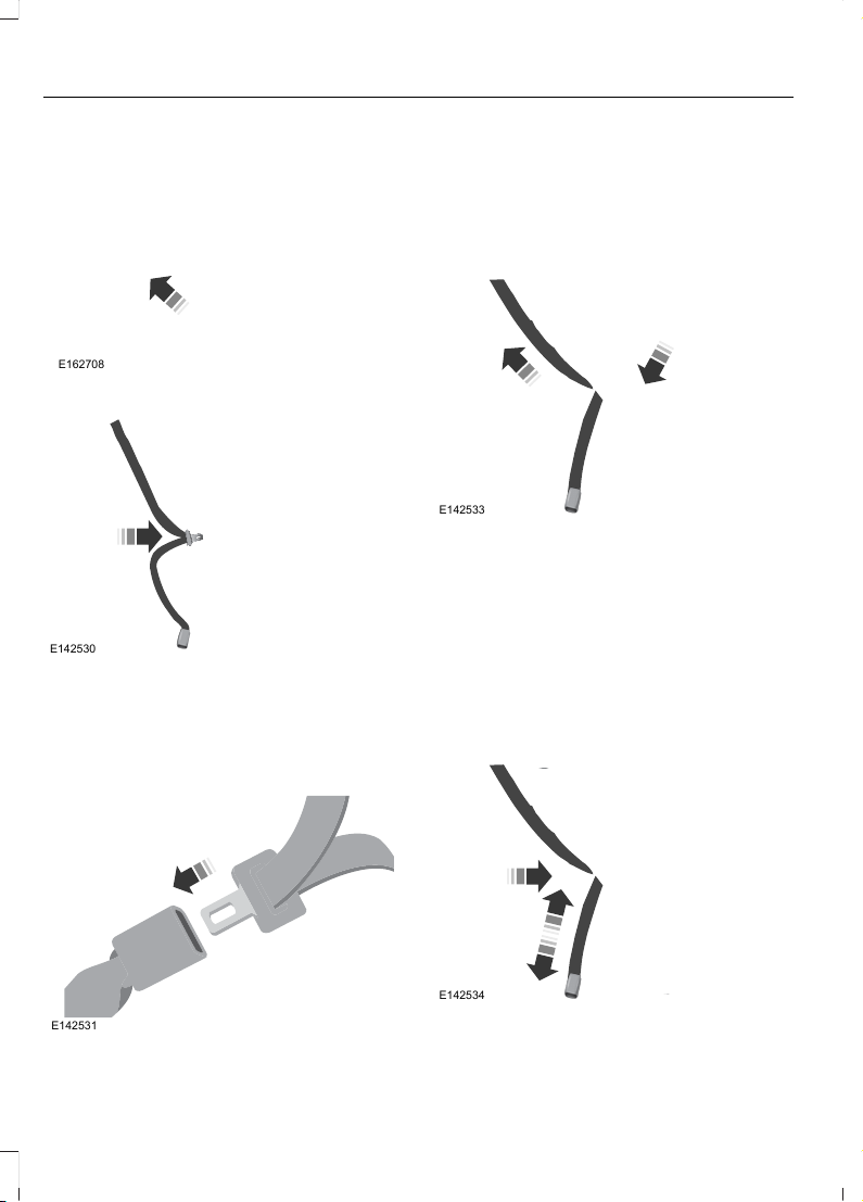
E162708
2. Slide the tongue up the webbing.
E142530
3. While holding both shoulder and lap
portions next to the tongue, route the
tongue and webbing through the child
seat according to the child seat
manufacturer's instructions. Be sure
that the belt webbing is not twisted.
E142531
4. Insert the belt tongue into the proper
buckle (the buckle closest to the
direction the tongue is coming from)
for that seating position until you hear
a snap and feel the latch engage. Make
sure the tongue is latched securely by
pulling on it.
E142533
5. While pushing down with your knee on
the child seat pull up on the shoulder
belt portion to tighten the lap belt
portion of the combination lap and
shoulder belt.
6. Allow the safety belt to retract and
remove any slack in the belt to securely
tighten the child safety seat in the
vehicle.
7. Attach the tether strap (if the child seat
is equipped).
E142534
22
F650750 (TBC), enUSA, First Printing
Child Safety
Page 26

8. Before placing the child in the seat,
forcibly move the seat forward and
back to make sure the seat is securely
held in place. To check this, grab the
seat at the belt path and attempt to
move it side to side and forward and
back. There should be no more than 1
inch (2.5 centimeters) of movement
for proper installation.
9. Check from time to time to be sure that
there is no slack in the lap and shoulder
belt. The shoulder belt must be snug
to keep the lap belt tight during a crash.
Ford recommends checking with a NHTSA
Certified Child Passenger Safety
Technician to make certain the child
restraint is properly installed. In Canada,
check with your local St. John Ambulance
office for referral to a Child Passenger
Safety Technician.
Using Lower Anchors and Tethers
for CHildren (LATCH)
The LATCH system is composed of three
vehicle anchor points: two lower anchors
located where the vehicle seatback and
seat cushion meet (called the seat bight)
and one top tether anchor located behind
that seating position. Your vehicle is not
equipped with the lower anchor points in
the seat bight. For this vehicle, use the
vehicle safety belt and upper tether to
secure a child seat.
Using Tether Straps
Many forward-facing child safety seats
include a tether strap which extends from
the back of the child safety seat and hooks
to an anchoring point called the top tether
anchor. Tether straps are available as an
accessory for many older safety seats.
Contact the manufacturer of your child
seat for information about ordering a
tether strap, or to obtain a longer tether
strap if the tether strap on your safety seat
does not reach the appropriate top tether
anchor in the vehicle.
The passenger seats of your vehicle may
be equipped with built-in tether strap
anchors located behind the seats as
described below.
The tether strap anchors in your vehicle
are in the following positions (shown from
top view):
23
F650750 (TBC), enUSA, First Printing
Child Safety
Page 27
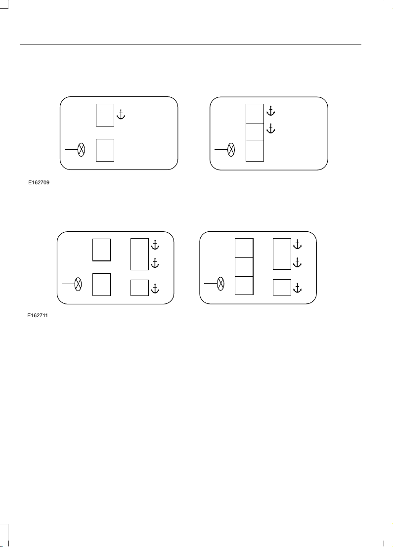
F-Series Regular Cab
E162709
F-Series Crew Cab
E162711
Attach the tether strap only to the
appropriate tether anchor as shown. The
tether strap may not work properly if
attached somewhere other than the
correct tether anchor.
Once the child safety seat has been
installed using the safety belt, you can
attach the top tether strap.
Tether Strap Attachment
1. Route the child safety seat tether strap
over the back of the seat.
Note: For vehicles with adjustable head
restraints, route the tether strap under the
head restraint and between the head
restraint posts, otherwise route the tether
strap over the top of the seat back. If the
top of the safety seat hits the head restraint,
raise the head restraint to let the child seat
fit further rearward.
2. Locate the correct anchor for the
selected seating position.
3. You may need to pull the seatback
forward to access the tether anchors.
Make sure the seat is locked in the
upright position before installing the
child seat.
24
F650750 (TBC), enUSA, First Printing
Child Safety
Page 28
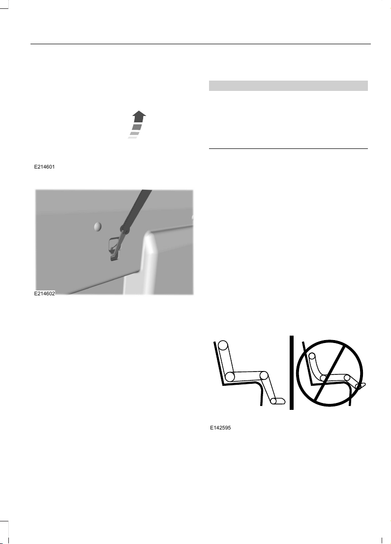
E214601
4. Remove the tether cover.
E214602
5. Clip the tether strap to the anchor as
shown.
Front seats (Regular Cab) and Rear
seats (Crew Cab)
If the tether strap is clipped incorrectly, the
child safety seat may not be retained
properly in the event of a crash.
6. Tighten the child safety seat tether strap
according to the manufacturer's
instructions.
If the safety seat is not anchored properly,
the risk of a child being injured in a crash
greatly increases.
If your child restraint system is equipped
with a tether strap, and the child restraint
manufacturer recommends its use, Ford
also recommends its use.
BOOSTER SEATS
WARNING
Never place, or allow a child to place,
the shoulder belt under a child's arm
or behind the back because it
reduces the protection for the upper part
of the body and may increase the risk of
injury or death in a crash.
Use a belt-positioning booster seat for
children who have outgrown or no longer
properly fit in a child safety seat (generally
children who are less than 4 feet 9 inches
(1.45 meters) tall, are greater than age four
(4) and less than age twelve (12), and
between 40 pounds (18 kilograms) and
80 pounds (36 kilograms) and upward to
100 pounds (45 kilograms) if
recommended by your child restraint
manufacturer). Many state and provincial
laws require that children use approved
booster seats until they reach age eight, a
height of 4 feet 9 inches (1.45 meters) tall,
or 80 pounds (36 kilograms).
Booster seats should be used until you can
answer YES to ALL of these questions
when seated without a booster seat:
E142595
25
F650750 (TBC), enUSA, First Printing
Child Safety
Page 29
• Can the child sit all the way back
against their vehicle seat back with
knees bent comfortably at the edge of
the seat cushion?
• Can the child sit without slouching?
• Does the lap belt rest low across the
hips?
• Is the shoulder belt centered on the
shoulder and chest?
• Can the child stay seated like this for
the whole trip?
Always use booster seats in conjunction
with your vehicle lap and shoulder belt.
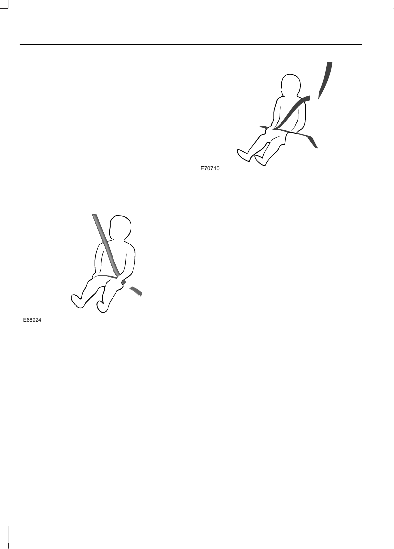
Types of Booster Seats
E68924
• Backless booster seats
If your backless booster seat has a
removable shield, remove the shield. If a
vehicle seating position has a low seat
back or no head restraint, a backless
booster seat may place your child's head
(as measured at the tops of the ears)
above the top of the seat. In this case,
move the backless booster to another
seating position with a higher seat back or
head restraint and lap and shoulder belts,
or consider using a high back booster seat.
E70710
• High back booster seats
If, with a backless booster seat, you cannot
find a seating position that adequately
supports your child's head, a high back
booster seat would be a better choice.
Children and booster seats vary in size and
shape. Choose a booster that keeps the
lap belt low and snug across the hips,
never up across the stomach, and lets you
adjust the shoulder belt to cross the chest
and rest snugly near the center of the
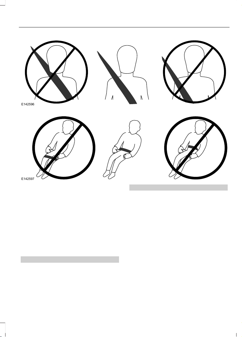
shoulder. The following drawings compare
the ideal fit (center) to a shoulder belt
uncomfortably close to the neck and a
shoulder belt that could slip off the
shoulder. The drawings also show how the
lap belt should be low and snug across the
child's hips.
26
F650750 (TBC), enUSA, First Printing
Child Safety
Page 30
E142596
E142597
If the booster seat slides on the vehicle
seat upon which it is being used, placing a
rubberized mesh sold as shelf or carpet
liner under the booster seat may improve
this condition. Do not introduce any item
thicker than this under the booster seat.
Check with the booster seat
manufacturer's instructions.
CHILD RESTRAINT POSITIONING
WARNINGS
Airbags can kill or injure a child in a
child seat. Never place a rear-facing
child seat in front of an active airbag.
If you must use a forward-facing child seat
in the front seat, move the vehicle seat
upon which the child seat is installed all
WARNINGS
the way back. When possible, all children
age 12 and under should be properly
restrained in a rear seating position. If all
children cannot be seated and restrained
properly in a rear seating position, properly
restrain the largest child in the front seat.
Always carefully follow the
instructions and warnings provided
by the manufacturer of any child
restraint to determine if the restraint device
is appropriate for your child's size, height,
weight, or age. Follow the child restraint
manufacturer's instructions and warnings
provided for installation and use in
conjunction with the instructions and
warnings provided by your vehicle
27
F650750 (TBC), enUSA, First Printing
Child Safety
Page 31

WARNINGS
manufacturer. A safety seat that is
improperly installed or utilized, is
inappropriate for your child's height, age,
or weight or does not properly fit the child
may increase the risk of serious injury or
death.
Never let a passenger hold a child on
his or her lap while your vehicle is
moving. The passenger cannot
protect the child from injury in a crash,
which may result in serious injury or death.
Never use pillows, books, or towels
to boost a child. They can slide
around and increase the likelihood
of injury or death in a crash.
WARNINGS
Always restrain an unoccupied child
seat or booster seat. These objects
may become projectiles in a crash or
sudden stop, which may increase the risk
of serious injury.
Never place, or allow a child to place,
the shoulder belt under a child's arm
or behind the back because it
reduces the protection for the upper part
of the body and may increase the risk of
injury or death in a crash.
To avoid risk of injury, do not leave
children or pets unattended in your
vehicle.
Recommendations for attaching child safety restraints for children
Use any attachment method as indicated below by XCombined
child and
seat
weight
Restraint
Type
Safety belt
only
Safety belt
and LATCH
(lower
anchors
and top
tether
anchor)
Safety belt
and top
tether
anchor
LATCH
(lower
anchors
only)
LATCH
(lower
anchors
and top
tether
anchor)
XUp to 65 lb
(29.5 kg)
Rear facing
child seat
XOver 65 lb
(29.5 kg)
Rear facing
child seat
XUp to 65 lb
(29.5 kg)
Forward
facing
child seat
XOver 65 lb
(29.5 kg)
Forward
facing
child seat
Note: The child seat must rest tightly
against the vehicle seat upon which it is
installed. It may be necessary to lift or
remove the head restraint. See Head
Restraints (page 73).
CHILD SAFETY LOCKS
When these locks are set, the rear doors
cannot be opened from the inside.
28
F650750 (TBC), enUSA, First Printing
Child Safety
Page 32

E162719
The childproof locks are located on the
rear edge of each rear door. You must set
the lock separately for each door.
Move the lock control up or down to
engage or disengage the childproof lock.
29
F650750 (TBC), enUSA, First Printing
Child Safety
Page 33
PRINCIPLE OF OPERATION
WARNINGS
Always drive and ride with the seat
backrest upright and the lap belt
snug and low across the hips.
To reduce the risk of injury, make
sure children sit where they can be
properly restrained.
Never let a passenger hold a child on
his or her lap while your vehicle is
moving. The passenger cannot
protect the child from injury in a crash
which may result in serious injury or death.
All occupants of the vehicle,
including the driver, should always
properly wear their safety belts, even
when an airbag supplemental restraint
system is provided. Failure to properly wear
your safety belt could seriously increase
the risk of injury or death.
It is extremely dangerous to ride in a
cargo area, inside or outside of a
vehicle. In a crash, people riding in
these areas are more likely to be seriously
injured or killed. Do not allow people to ride
in any area of your vehicle that is not
equipped with seats and safety belts. Be
sure everyone in your vehicle is in a seat
and using a safety belt properly.
In a rollover crash, an unbelted
person is significantly more likely to
die than a person wearing a safety
belt.
Each seating position in your vehicle
has a specific safety belt assembly
which is made up of one buckle and
one tongue that are designed to be used
as a pair. 1) Use the shoulder belt on the
outside shoulder only. Never wear the
shoulder belt under the arm. 2) Never
swing the safety belt around your neck over
the inside shoulder. 3) Never use a single
belt for more than one person.
WARNINGS
When possible, all children 12 years
old and under should be properly
restrained in a rear seating position.
Failure to follow this could seriously
increase the risk of injury or death.
Safety belts and seats can become
hot in a vehicle that has been closed
up in sunny weather; they could burn
a small child. Check seat covers and
buckles before you place a child anywhere
near them.
Front and rear seat occupants,
including pregnant women, should
wear safety belts for optimum
protection in an accident.
All seating positions in this vehicle have
lap and shoulder safety belts. All
occupants of the vehicle should always
properly wear their safety belts, even when
an airbag supplemental restraint system
is provided.
The safety belt system consists of:
• Lap and shoulder safety belts.
• Shoulder safety belt with automatic
locking mode, (except driver safety
belt).
• Height adjuster at the front outboard
seating positions.
• Safety belt pretensioner at the front
outboard seating positions.
• Safety belt warning light and chime.
FASTENING THE SEATBELTS
The front outboard and rear safety
restraints in the vehicle are combination
lap and shoulder belts.
30
F650750 (TBC), enUSA, First Printing
Seatbelts
Page 34
E142587
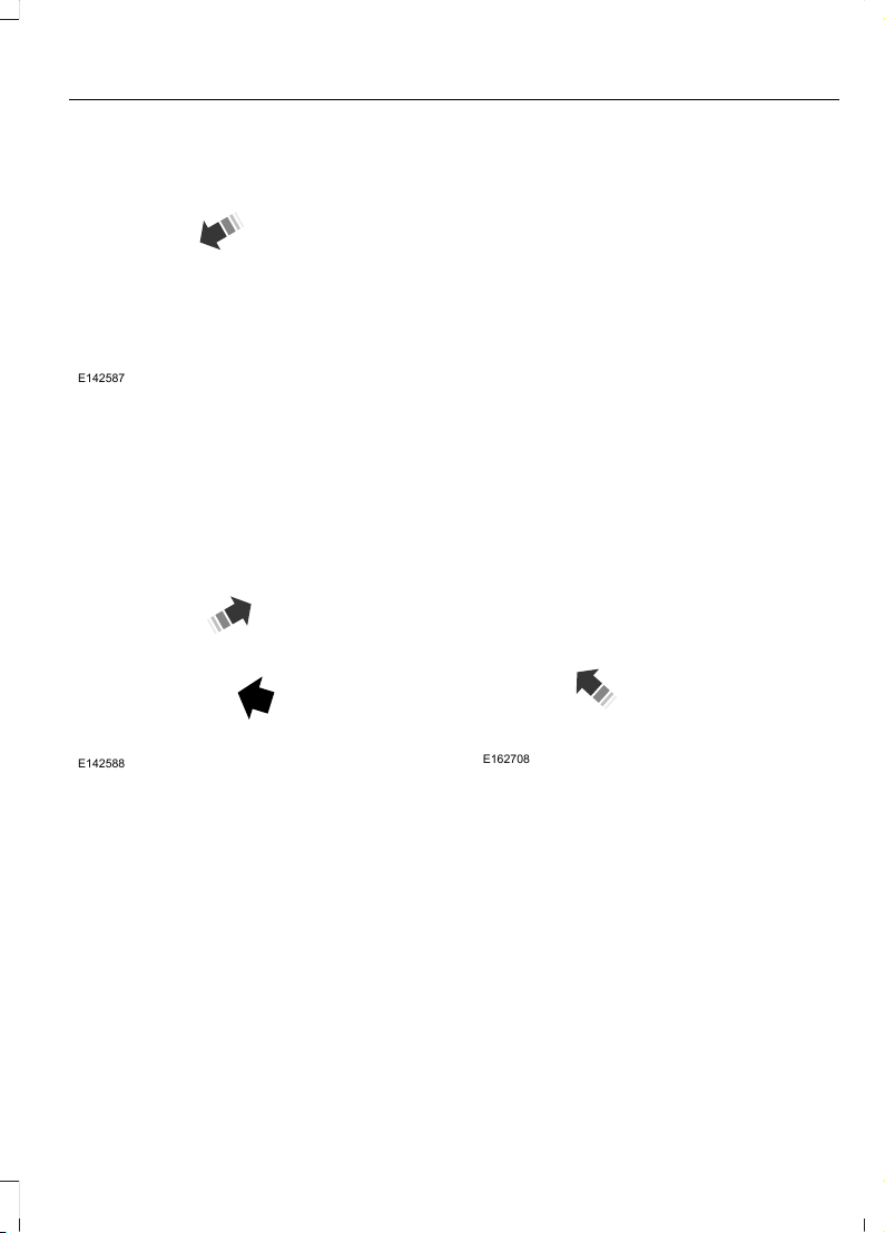
1. Insert the belt tongue into the proper
buckle (the buckle closest to the
direction the tongue is coming from)
until you hear a snap and feel it latch.
Make sure the tongue is securely
fastened in the buckle.
E142588
2. To unfasten, press the release button
and remove the tongue from the
buckle.
Using the Safety Belt with Cinch
Tongue (Front Center and Rear
Center Seats Only)
The cinch tongue will slide up and down
the belt webbing when the belt is stowed
or while putting safety belts on. When the
lap and shoulder safety belt is buckled, the
cinch tongue will allow the lap portion to
be shortened, but pinches the webbing to
keep the lap portion from getting longer.
The cinch tongue is designed to slip during
a crash, so always wear the shoulder belt
properly and do not allow any slack in
either the lap or shoulder portions.
Before you can reach and latch a lap and
shoulder belt having a cinch tongue into
the buckle, you may have to lengthen the
lap belt portion of it.
E162708
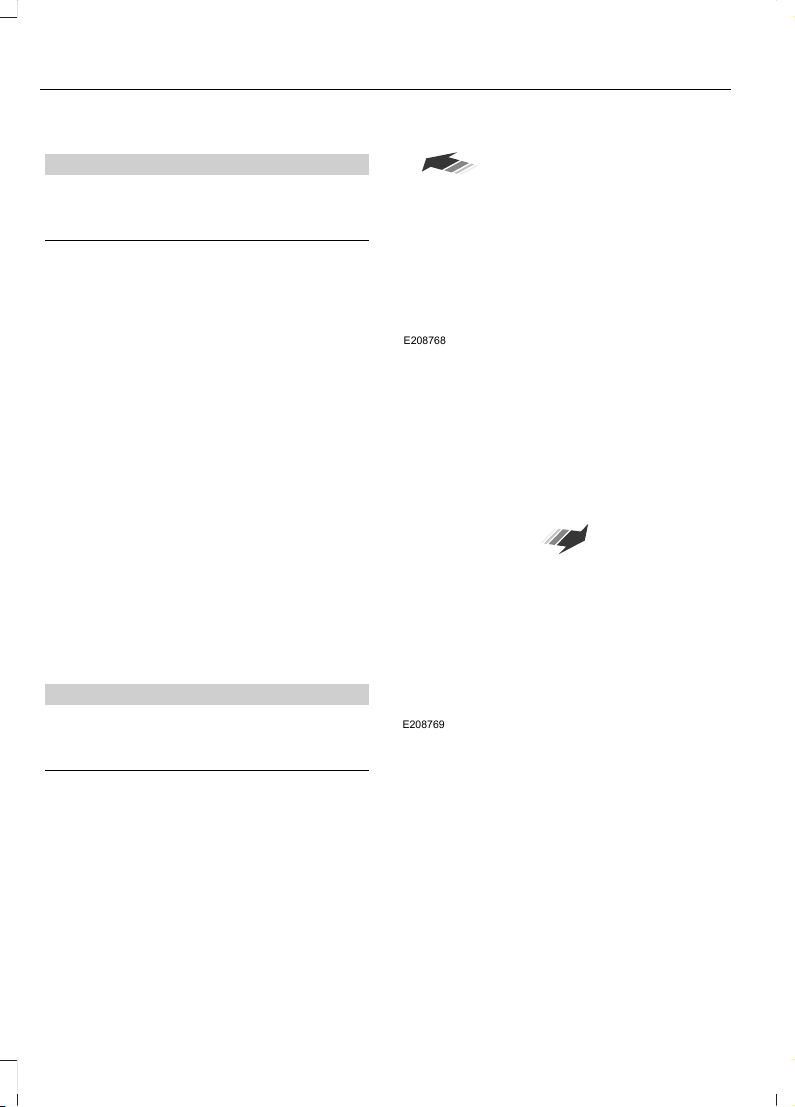
1. To lengthen the lap belt, pull some
webbing out of the shoulder belt
retractor.
2. While holding the webbing below the
tongue, grasp the tip (metal portion)
of the tongue so that it is parallel to the
webbing and slide the tongue upward.
3. Provide enough lap belt length so that
the tongue can reach the buckle.
31
F650750 (TBC), enUSA, First Printing
Seatbelts
Page 35
Fastening the Cinch Tongue
WARNING
The lap belt should fit snugly and as
low as possible around the hips, not
across the waist.
1. Pull the lap and shoulder belt from the
retractor so that the shoulder belt
portion of the safety belt crosses your
shoulder and chest.
2. Be sure the belt is not twisted. If the
belt is twisted, remove the twist.
3. Insert the belt tongue into the proper
buckle for your seating position until
you hear a snap and feel it latch.
4. Make sure the tongue is securely
fastened to the buckle by pulling on
the tongue.
While you are fastened in the safety belt,
the lap and shoulder belt with a cinch
tongue adjusts to your movement.
However, if you brake hard, turn hard, or if
your vehicle receives an impact of 5.0 mph
(8 km/h) or more, the safety belt will
become locked and help reduce your
forward movement.
Lap Belts
WARNING
The lap belt should fit snugly and as
low as possible around the hips, not
across the waist.
The front center lap belt does not adjust
automatically.
E208768
Insert the tongue into the correct buckle
(the buckle closest to the direction the
tongue is coming from). To lengthen the
belt, turn the tongue at a right angle to the
belt and pull across your lap until it reaches
the buckle. To tighten the belt, pull the
loose end of the belt through the tongue
until it fits snugly across the hips.
Shorten and fasten the belt when not in
use.
32
F650750 (TBC), enUSA, First Printing
Seatbelts
Page 36
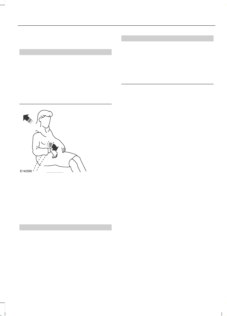
Using Safety Belts During
Pregnancy
WARNING
Always ride and drive with your
seatback upright and the safety belt
properly fastened. The lap portion of
the safety belt should fit snug and be
positioned low across the hips. The
shoulder portion of the safety belt should
be positioned across the chest. Pregnant
women should also follow this practice.
See the following figure.
E142590
Pregnant women should always wear their
safety belt. Position the lap belt portion of
a combination lap and shoulder belt low
across the hips below the belly and worn
as tight as comfort will allow. Position the
shoulder belt to cross the middle of the
shoulder and the center of the chest.
Safety Belt Locking Modes
WARNINGS
After any vehicle crash, the safety
belt system at all passenger seating
positions must be checked by an
authorized dealer to verify that the
automatic locking retractor feature for
child seats is still functioning properly. In
addition, all safety belts should be checked
for proper function.
WARNINGS
The belt and retractor must be
replaced if the safety belt assembly
automatic locking retractor feature
or any other safety belt function is not
operating properly when checked by an
authorized dealer. Failure to replace the
belt and retractor assembly could increase
the risk of injury in crashes.
The safety restraints in the vehicle are
combination lap and shoulder belts. The
driver safety belt has the first type of
locking mode. The front outboard
passenger and rear outboard seat safety
belts have both types of locking modes
described as follows:
Vehicle Sensitive Mode
This is the normal retractor mode, which
allows free shoulder belt length
adjustment to your movements and
locking in response to vehicle movement.
For example, if the driver brakes suddenly
or turns a corner sharply, or the vehicle
receives an impact of about 5 mph
(8 km/h) or more, the combination safety
belts will lock to help reduce forward
movement of the driver and passengers.
In addition, the retractor is designed to lock
if the webbing is pulled out too quickly. If
this occurs, let the belt retract slightly and
pull webbing out again in a slow and
controlled manner.
Automatic Locking Mode
In this mode, the shoulder belt is
automatically pre-locked. The belt will still
retract to remove any slack in the shoulder
belt. The automatic locking mode is not
available on the driver safety belt or
optional front center or rear center safety
belt.
33
F650750 (TBC), enUSA, First Printing
Seatbelts
Page 37
When to Use the Automatic Locking
Mode
Use this mode any time a child safety seat,
except a booster, is installed in passenger
front or rear seating positions. You should
properly restrain children 12 years old and
under in a rear seating position whenever
possible. See Child Safety (page 17).
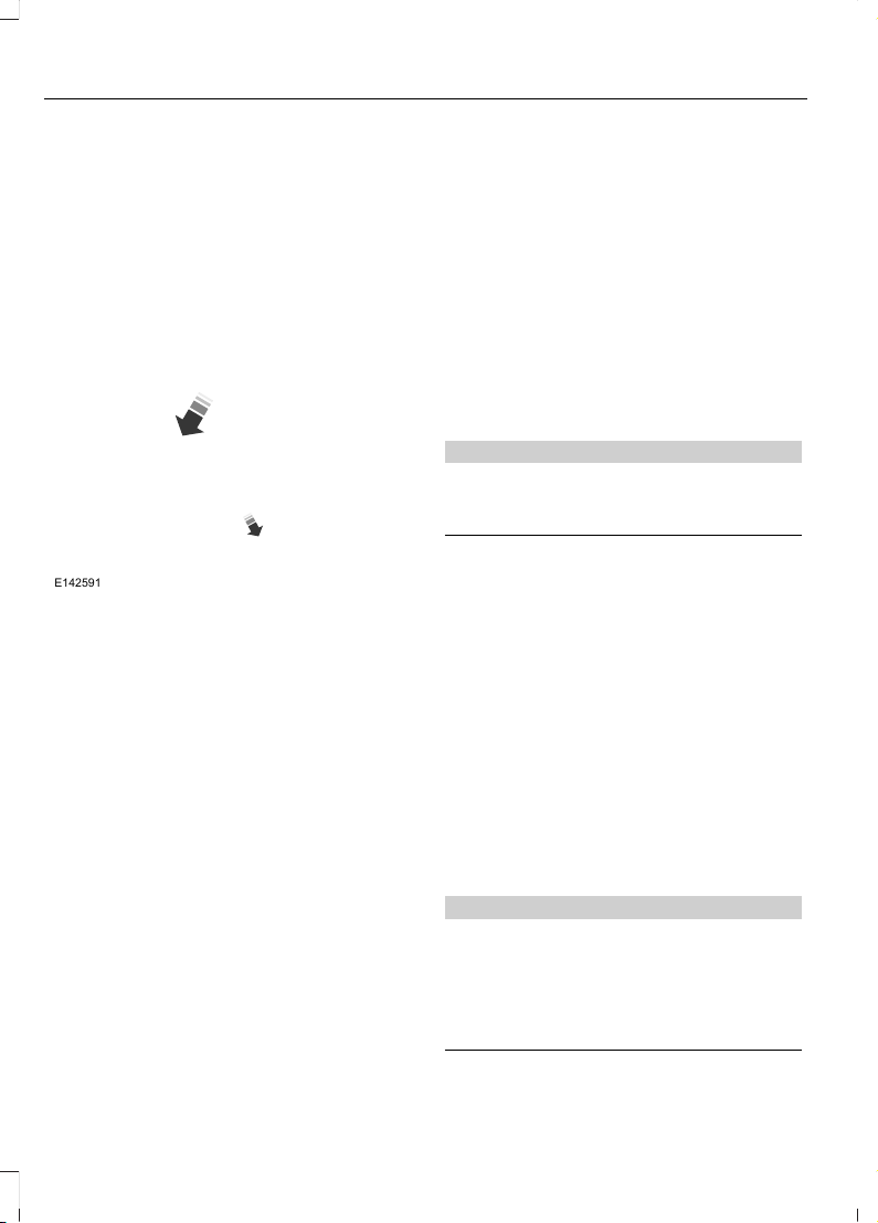
How to Use the Automatic Locking Mode
E142591
1. Buckle the combination lap and
shoulder belt.
2. Grasp the shoulder portion and pull
downward until the entire belt is pulled
out.
3. Allow the belt to retract. As the belt
retracts, you will hear a clicking sound.
This indicates the safety belt is now in
the automatic locking mode.
How to Disengage the Automatic Locking
Mode
Unbuckle the combination lap and
shoulder belt and allow it to retract
completely to disengage the automatic
locking mode and activate the vehicle
sensitive (emergency) locking mode.
Energy Management Feature
• This vehicle has a safety belt system
with an energy management feature
at the front outboard seating positions
to help further reduce the risk of injury
in the event of a head-on crash.
• The front outboard safety belt systems
have a retractor assembly that is
designed to pay out webbing in a
controlled manner. This feature is
designed to help reduce the belt force
acting on the occupant’s chest.
Safety Belt Extension Assembly
WARNING
Do not use extensions to change the
fit of the shoulder belt across the
torso.
If the safety belt is too short when fully
extended, you can obtain a safety belt
extension assembly from an authorized
dealer.
Use only extensions manufactured by the
same supplier as the safety belt.
Manufacturer identification is on a label
located either at the end of the webbing
or on the retractor behind the trim. Also,
use the safety belt extension only if the
safety belt is too short for you when fully
extended.
SEATBELT HEIGHT ADJUSTMENT
WARNING
Position the safety belt height
adjuster so that the belt rests across
the middle of your shoulder. Failure
to adjust the safety belt properly could
reduce the effectiveness of the safety belt
and increase the risk of injury in a crash.
34
F650750 (TBC), enUSA, First Printing
Seatbelts
Page 38
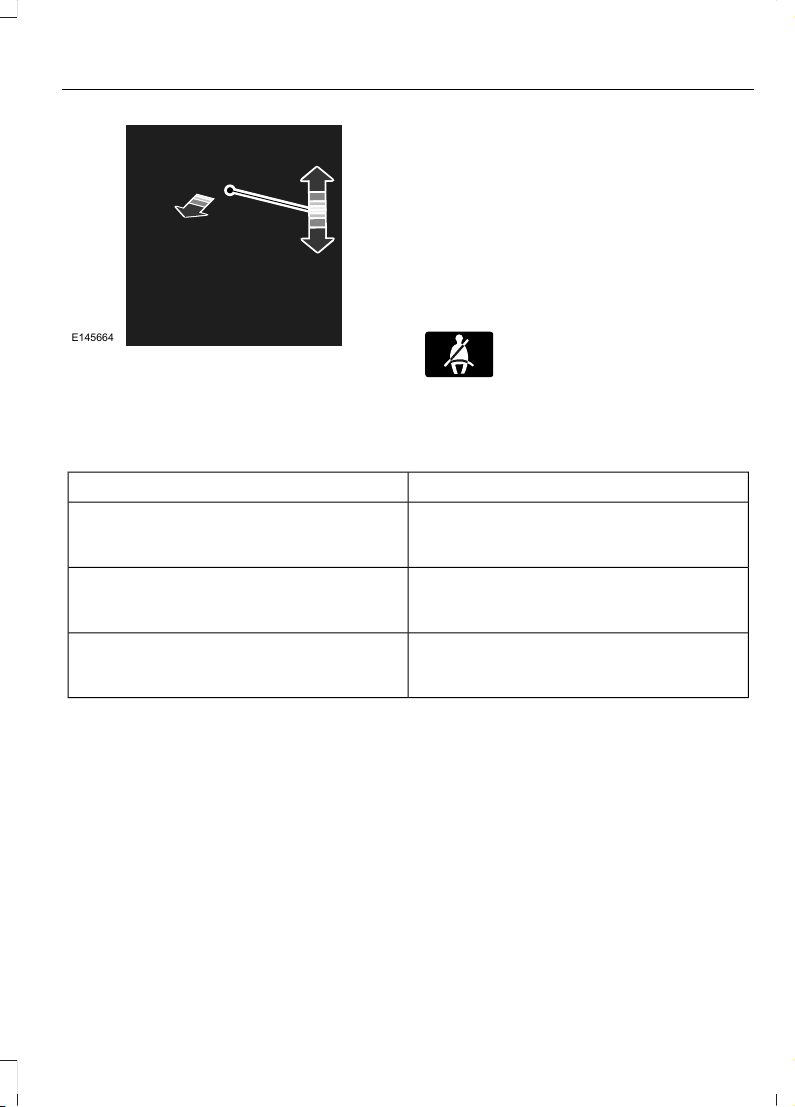
E145664
Adjust the height of the shoulder belt so
the belt rests across the middle of your
shoulder.
To adjust the shoulder belt height:
1. Pull the button and slide the height
adjuster up or down.
2. Release the button and pull down on
the height adjuster to make sure it is
locked in place.
SEATBELT WARNING LAMP AND INDICATOR CHIME
This lamp illuminates and an
audible warning will sound if the
driver's safety belt has not been
fastened when the vehicle's ignition is
turned on.
Conditions of operation
Then...If...
The safety belt warning light illuminates 1-
2 minutes and the warning chime sounds
4-8 seconds.
The driver's safety belt is not buckled
before the ignition switch is turned to the
on position...
The safety belt warning light and warning
chime turn off.
The driver's safety belt is buckled while the
indicator light is illuminated and the
warning chime is sounding...
The safety belt warning light and indicator
chime remain off.
The driver's safety belt is buckled before
the ignition switch is turned to the on posi-
tion...
SEATBELT REMINDER
Belt-Minder™
This feature supplements the safety belt
warning function by providing additional
reminders that intermittently sound a tone
and illuminate the safety belt warning light
when you are in the driver seat and the
safety belt is unbuckled.
35
F650750 (TBC), enUSA, First Printing
Seatbelts
Page 39
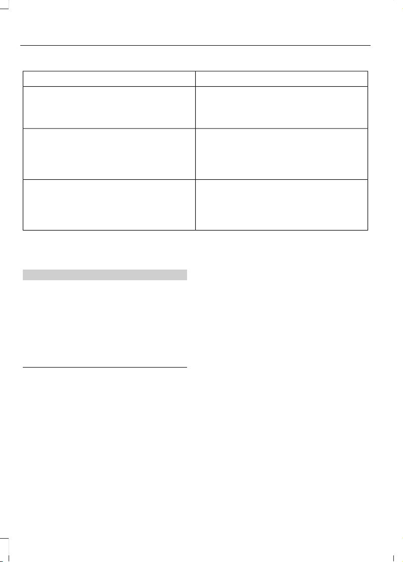
Then...If...
The Belt-Minder feature will not activate.You buckle your safety belt before you
switch the ignition switch on or less than 12 minutes elapse after you switch the igni-
tion on...
The Belt-Minder feature activates, the
safety belt warning light illuminates and a
warning tone sounds for six seconds every
25 seconds, repeating for about five
minutes or until you buckle the safety belt.
You do not buckle your safety belt before
your vehicle has reached at least 6 mph
(9.7 km/h) and 1-2 minutes elapse after
you switch the ignition on...
The Belt-Minder feature activates, the
safety belt warning light illuminates and a
warning tone sounds for six seconds every
25 seconds, repeating for about five
minutes or until you buckle the safety belt.
The safety belt for the driver is unbuckled
for about one minute while the vehicle is
traveling at least 6 mph (9.7 km/h) and
more than 1-2 minutes elapse after you
switch the ignition on...
Deactivating and Activating the
Belt-Minder Feature (Driver Only)
WARNING
While the system allows you to
deactivate it, this system is designed
to improve your chances of being
safely belted and surviving an accident.
We recommend you leave the system
activated for yourself and others who may
use the vehicle. To reduce the risk of injury,
do not deactivate or activate the system
while driving the vehicle.
Read Steps 1 - 4 thoroughly before
proceeding with the programming
procedure.
Deactivate or activate the system by
performing the following procedure:
Before following the procedure, make sure
that:
• The parking brake is set.
• The transmission is in park (P) (if
equipped) or neutral (N).
• The ignition is off.
• All vehicle doors are closed.
• The driver safety belt is unbuckled.
• The parking lamps and headlamps are
off.
1. Turn the ignition on. Do not start the
engine.
2. Wait until the safety belt warning light
turns off (about one or two minutes).
You must complete Steps 3–5 within
60 seconds after the safety belt
warning light turns off. If not
completed, you must repeat the
procedure.
3. Buckle then unbuckle the safety belt
three times at a moderate speed,
ending with the safety belt in the
unbuckled state. After Step 4, the
safety belt warning light turns on for
three seconds.
4. Within seven seconds of the light
turning on, buckle then unbuckle the
safety belt.
36
F650750 (TBC), enUSA, First Printing
Seatbelts
Page 40

• This will switch the feature off for the
seating position if it is currently on.
• This will switch the feature on for the
seating position if it is currently off.
The safety belt warning light flashing four
times per second for three seconds
provides confirmation of disabling
Belt-Minder.
The following sequence provides
confirmation of enabling Belt-Minder:
• The safety belt warning light flashing
four times per second for three
seconds.
• The safety belt warning light turning
off.
• The safety belt warning light flashing
four times per second for three
seconds.
After receiving confirmation, the procedure
is complete.
CHILD RESTRAINT AND SEATBELT MAINTENANCE
Inspect the vehicle safety belts and child
safety seat systems periodically to make
sure they work properly and are not
damaged. Inspect the vehicle and child
seat safety belts to make sure there are no
nicks, tears or cuts. Replace if necessary.
All vehicle safety belt assemblies, including
retractors, buckles, front safety belt buckle
assemblies, buckle support assemblies
(slide bar-if equipped), shoulder belt
height adjusters (if equipped), shoulder
belt guide on seat back (if equipped), child
safety seat LATCH and tether anchors, and
attaching hardware, should be inspected
after a crash. Read the child restraint
manufacturer's instructions for additional
inspection and maintenance information
specific to the child restraint.
Ford Motor Company recommends that
all safety belt assemblies in use in vehicles
involved in a crash be replaced. However,
if the crash was minor and an authorized
dealer finds that the belts do not show
damage and continue to operate properly,
they do not need to be replaced. Safety
belt assemblies not in use during a crash
should also be inspected and replaced if
either damage or improper operation is
noted.
Properly care for safety belts. See Vehicle
Care (page 225).
37
F650750 (TBC), enUSA, First Printing
Seatbelts
Page 41
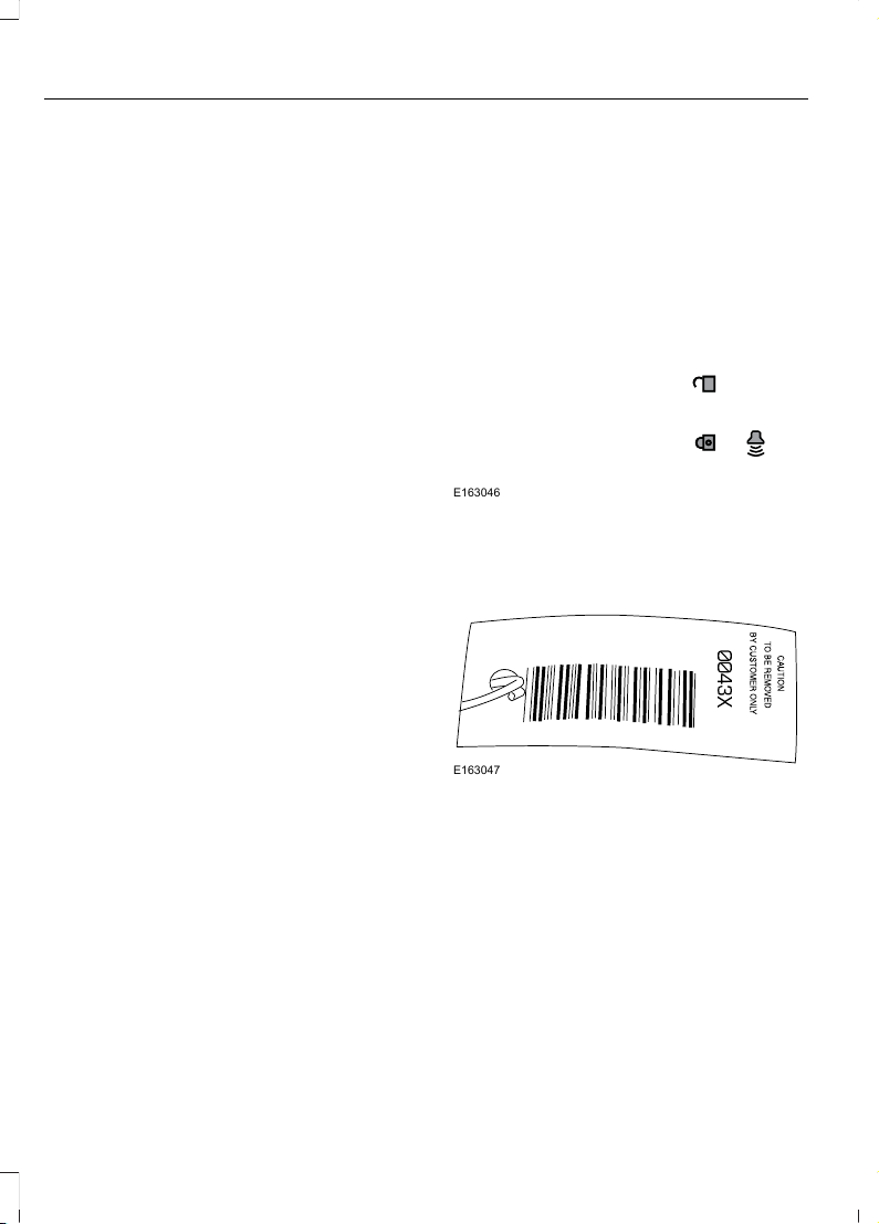
GENERAL INFORMATION ON RADIO FREQUENCIES
This device complies with Part 15 of the
FCC Rules and with Industry Canada
license-exempt RSS standard(s).
Operation is subject to the following two
conditions: (1) This device may not cause
harmful interference, and (2) This device
must accept any interference received,
including interference that may cause
undesired operation.
Note: Changes or modifications not
expressively approved by the party
responsible for compliance could void the
user's authority to operate the equipment.
The term IC before the radio certification
number only signifies that Industry Canada
technical specifications were met.
The typical operating range for your
transmitter is approximately 33 feet (10
meters). Vehicles with the remote start
feature will have a greater range. One of
the following could cause a decrease in
operating range:
• weather conditions
• nearby radio towers
• structures around the vehicle
• other vehicles parked next to your
vehicle
The radio frequency used by your remote
control can also be used by other short
distance radio transmissions, for example
amateur radios, medical equipment,
wireless headphones, remote controls and
alarm systems. If the frequencies are
jammed, you will not be able to use your
remote control. You can lock and unlock
the doors with the key.
Note: Make sure to lock your vehicle before
leaving it unattended.
Note: If you are in range, the remote control
will operate if you press any button
unintentionally.
Note: The remote control contains sensitive
electrical components. Exposure to moisture
or impact may cause permanent damage.
REMOTE CONTROL
Integrated Keyhead Transmitters
(If Equipped)
E163046
Use the key blade to start your vehicle and
unlock or lock the driver door from outside
your vehicle. The transmitter portion
functions as the remote control.
E163047
Note: Your vehicle’s keys came with a
security label that provides important
vehicle key cut information. Keep the label
in a safe place for future reference.
Replacing the Battery
Note: Refer to local regulations when
disposing of transmitter batteries.
Note: Do not wipe off any grease on the
battery terminals or on the back surface of
the circuit board.
38
F650750 (TBC), enUSA, First Printing
Keys and Remote Controls
Page 42
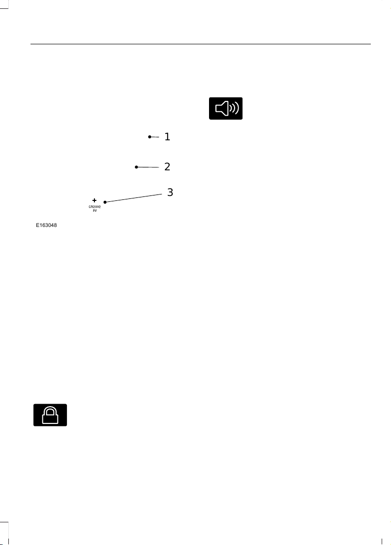
Note: Replacing the battery does not delete
the transmitter from the vehicle. The
transmitter should operate normally.
The remote control uses one coin-type
three-volt lithium battery CR2032 or
equivalent.
E163048
3
2
1
1. Twist a thin coin in the slot of the
transmitter near the key ring to remove
the battery cover.
2. Carefully peel up the rubber gasket
from the transmitter. It may come off
with the battery cover.
3. Remove the old battery.
4. Insert the new battery. Refer to the
instructions inside the transmitter for
the correct orientation of the battery.
Press the battery down to make sure
it is fully in the housing.
5. Reinstall the rubber gasket.
6. Snap the battery cover back onto the
transmitter.
Car Finder
E138623
Press the button twice within
three seconds. The horn sounds
and the direction indicators
flash. We recommend you use this method
to locate your vehicle, rather than using
the panic alarm.
Sounding a Panic Alarm
Note: The panic alarm only operates when
the ignition is off.
E138624
Press the button to activate the
alarm. Press the button again or
switch on the ignition on to
deactivate it.
REPLACING A LOST KEY OR REMOTE CONTROL
Replacement keys or remote controls can
be purchased from an authorized dealer.
Authorized dealers can program remote
controls for your vehicle. See Passive
Anti-Theft System (page 42).
39
F650750 (TBC), enUSA, First Printing
Keys and Remote Controls
Page 43
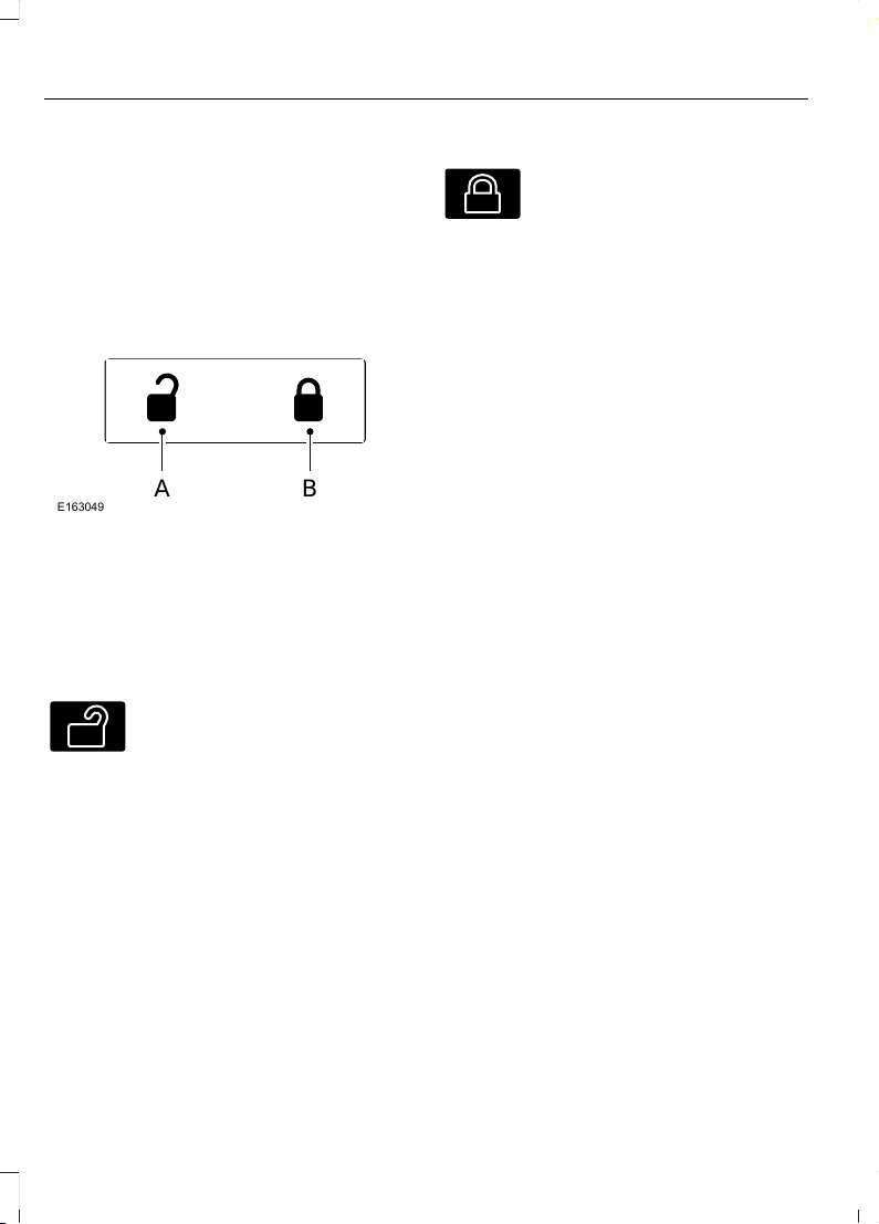
LOCKING AND UNLOCKING
You can use the power door lock control
or the remote control to lock and unlock
your vehicle.
Power Door Locks (If Equipped)
The power door lock control is on the driver
and front passenger door panels.
A B
E163049
UnlockA
LockB
Remote Control (If Equipped)
Unlocking the Doors (Two-Stage
Unlock)
E138629
Press the button to unlock the
driver door.
Press the button again within
three seconds to unlock all doors. The turn
signals will flash.
Press and hold both the lock and unlock
buttons on the remote control for four
seconds to disable or enable two-stage
unlocking. Disabling two-stage unlocking
allows all vehicle doors to unlock with one
press of the button. The turn signals will
flash twice to indicate a change to the
unlocking mode. The unlocking mode
applies to the remote control and keyless
entry keypad.
Locking the Doors
E138623
Press the button to lock all the
doors. The turn signals will
illuminate.
Press the button again within three
seconds to confirm that all the doors are
closed. The doors will lock again, the horn
will sound and the turn signals will
illuminate if all the doors are closed.
Mislock
If any door is open or if the hood is open on
vehicles with an anti-theft alarm or remote
start, the horn will sound twice and the
lamps will not flash.
Smart Unlocks (If Equipped)
This feature helps to prevent you from
locking yourself out of your vehicle if your
key is still in the ignition.
When you open the driver door and lock
your vehicle with the power door lock
control, all the doors will lock then unlock
if your key is still in the ignition.
Your can still lock your vehicle with the key
in the ignition by:
• using the manual lock on the door
• locking the driver door with a key
• using the keyless entry keypad
• using the lock button on the remote
control
Autolock and Autounlock (If Equipped)
The autolock feature will lock all the doors
when:
• all doors are closed, and
• the ignition is on, and
• you shift into any gear putting your
vehicle in motion, and
• your vehicle attains a speed greater
than 12 mph (20 km/h).
40
F650750 (TBC), enUSA, First Printing
Locks
Page 44

The autolock feature will unlock all the
doors when:
• autolock has locked the doors
• you stop the vehicle and switch the
ignition off or to accessory mode, and
• you open the driver door within 10
minutes.
Note: The doors will not autounlock if you
have electronically locked them before
opening the driver door.
Enabling or Disabling
You can enable or disable these features
in the information display or your
authorized dealer can do it for you. See
General Information (page 62).
Note: You can enable or disable the
autolock and autounlock features
independently of each other.
Illuminated Entry
The interior lamps and select exterior
lamps will illuminate when you unlock the
doors with the remote entry system.
The illuminated entry system will turn off
the lights if:
• the ignition is on
• you press the remote control lock
button, or
• after 25 seconds of illumination.
The dome lamp will not turn on if the
control is set to the off position.
The lights will not turn off if:
• you turn them on with the dimmer
control, or
• any door is open.
Battery Saver
The battery saver turns off the interior
lamps 30 minutes after you switch the
ignition off if a door is open and the dome
lamp switch is on. It turns off the interior
lamps after 10 minutes if the dome lamp
switch is off.
41
F650750 (TBC), enUSA, First Printing
Locks
Page 45

PASSIVE ANTI-THEFT SYSTEM (If Equipped)
Note: The system is not compatible with
non-Ford aftermarket remote start systems.
Use of these systems may result in vehicle
starting problems and a loss of security
protection.
Note: Metallic objects, electronic devices
or a second coded key on the same key
chain may cause vehicle starting problems
if they are too close to the key when starting
the engine. Prevent these objects from
touching the coded key while starting the
engine. Switch the ignition off, move all
objects on the key chain away from the
coded key and restart the engine if a
problem occurs.
Note: Do not leave a duplicate coded key
in the vehicle. Always take your keys and
lock all doors when leaving the vehicle.
SecuriLock™
The system is an engine immobilization
system. It helps prevent the engine from
starting unless you use a coded key
programmed to your vehicle. Using the
wrong key may prevent the engine from
starting. A message may appear in the
information display.
If you are unable to start the engine with a
correctly coded key, the system has
malfunctioned. A message may appear in
the information display.
Automatic Arming
The system arms immediately after you
switch the ignition off.
Automatic Disarming
Switching the ignition on with a coded key
disarms the system.
Replacement Keys
Note: Your vehicle may have two integrated
keyhead transmitters.
The integrated keyhead transmitter
functions as a programmed ignition key. It
operates all the locks, starts the vehicle
and acts as a remote control.
If your programmed transmitters or
standard SecuriLock coded keys are lost
or stolen and you do not have an extra
coded key, you will need to have your
vehicle towed to an authorized dealer. You
need to erase the key codes from your
vehicle and program new coded keys.
Store an extra programmed key away from
your vehicle in a safe place to help prevent
any inconveniences. See an authorized
dealer to purchase additional spare or
replacement keys.
Programming a Spare Key
Note: You can program a maximum of eight
coded keys to your vehicle. Only four of
these can be integrated keyhead
transmitters.
You can program your own integrated
keyhead transmitter or standard
SecuriLock coded keys to your vehicle. This
procedure will program both the engine
immobilizer keycode and the remote entry
portion of the remote control to your
vehicle.
Only use integrated keyhead transmitters
or standard SecuriLock keys.
You must have two previously
programmed coded keys and the new
unprogrammed key readily accessible. See
an authorized dealer to have the spare key
programmed if two previously
programmed coded keys are not available.
Read and understand the entire procedure
before you begin.
42
F650750 (TBC), enUSA, First Printing
Security
Page 46

1. Insert the first previously programmed
coded key into the ignition.
2. Switch the ignition from off to on. Keep
the ignition on for at least three
seconds, but no more than 10 seconds.
3. Switch the ignition off and remove the
first coded key from the ignition.
4. After three seconds but within 10
seconds of switching the ignition off,
insert the second previously coded key
into the ignition.
5. Switch the ignition from off to on. Keep
the ignition on for at least three
seconds, but no more than 10 seconds.
6. Switch the ignition off and remove the
second previously programmed coded
key from the ignition.
7. After three seconds but within 10
seconds of switching the ignition off
and removing the previously
programmed coded key, insert the new
unprogrammed key into the ignition.
8. Switch the ignition from off to on. Keep
the ignition on for at least six seconds
until you hear the door locks cycle.
9. Remove the newly programmed coded
key from the ignition.
The key will start the engine if
programming is successful. You can
operate the remote entry system if the new
key is an integrated keyhead transmitter.
If programming was not successful, wait
20 seconds and repeat Steps 1 through 8.
If you are still unsuccessful, take your
vehicle to an authorized dealer.
43
F650750 (TBC), enUSA, First Printing
Security
Page 47
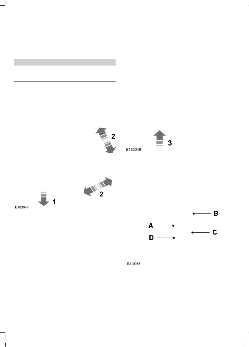
ADJUSTING THE STEERING WHEEL
WARNING
Do not adjust the steering wheel
when your vehicle is moving.
Note: Make sure that you are sitting in the
correct position. See Sitting in the Correct
Position (page 73).
E183047
1. Unlock the steering column.
2. Adjust the steering wheel to the desired
position.
E183049
3. Lock the steering column.
AUDIO CONTROL (If Equipped)
You can operate the following functions
with the control:
E210085
Seek up or next.A
Media.B
Volume up and down.C
Seek down or previous.D
44
F650750 (TBC), enUSA, First Printing
Steering Wheel
Page 48
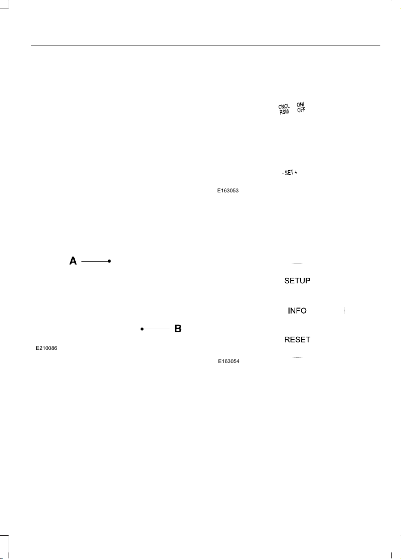
Media
Press repeatedly to scroll through available
audio modes.
Seek, Next or Previous
Press the seek button to:
• Tune the radio to the next or previous
stored preset.
• Play the next or the previous track.
Press and hold the seek button to:
• Tune the radio to the next station up
or down the frequency band.
• Seek through a track.
VOICE CONTROL (If Equipped)
E210086
Voice recognition.A
End call.B
CRUISE CONTROL
E163053
See Cruise Control (page 134).
INFORMATION DISPLAY CONTROL
E163054
See Information Displays (page 62).
45
F650750 (TBC), enUSA, First Printing
Steering Wheel
Page 49
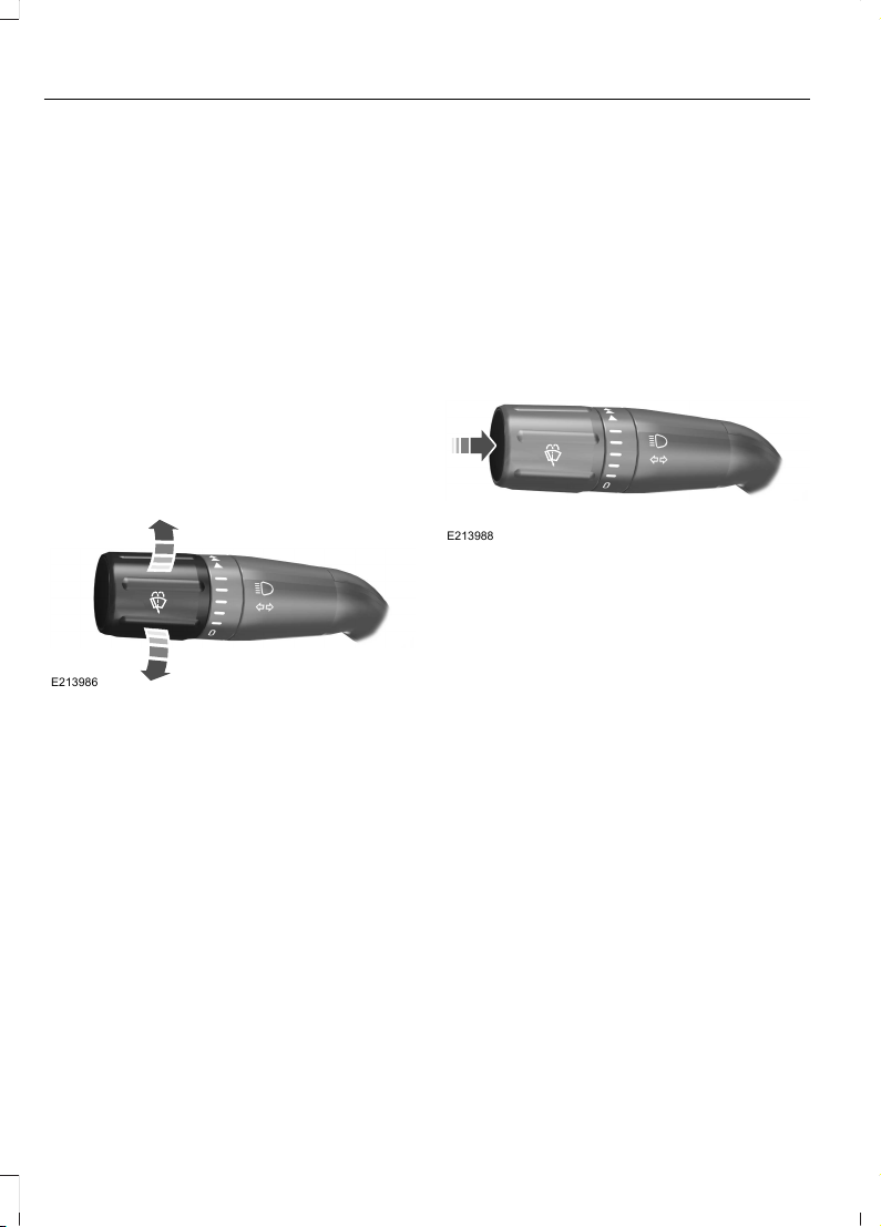
WINDSHIELD WIPERS
Note: Fully defrost the windshield before
switching on the windshield wipers.
Note: Make sure you switch off the
windshield wipers before entering a car
wash.
Note: Clean the windshield and wiper
blades if they begin to leave streaks or
smears. If that does not resolve the issue,
install new wiper blades.
Note: Do not operate the wipers on a dry
windshield. This may scratch the glass,
damage the wiper blades or cause the wiper
motor to burn out. Always use the
windshield washers before wiping a dry
windshield.
E213986
Rotate the end of the control:
• Away from you to increase the wiper
speed.
• Toward you to decrease the wiper
speed.
WINDSHIELD WASHERS
Note: Do not operate the wipers on a dry
windshield. This may scratch the glass,
damage the wiper blades or cause the wiper
motor to burn out. Always use the
windshield washer before wiping a dry
windshield.
Note: Do not operate the washers when
the washer reservoir is empty. This may
cause the washer pump to overheat.
Press the end of the stalk to activate the
washer.
• A brief press causes a single wipe
without washer fluid.
• A quick press and hold causes the
wipers to swipe three times with
washer fluid.
• A long press and hold activates the
wipers and washer fluid for up to 10
seconds.
E213988
46
F650750 (TBC), enUSA, First Printing
Wipers and Washers
Page 50
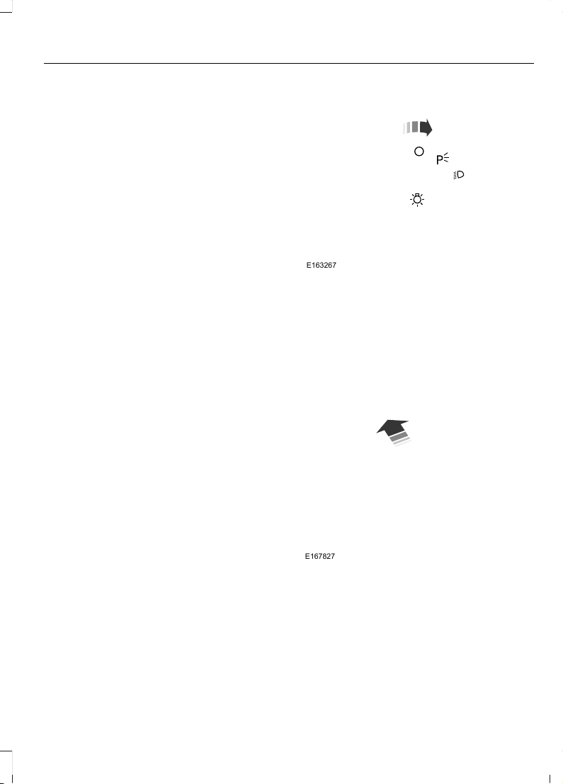
GENERAL INFORMATION
Condensation in Lamp Assemblies
Exterior lamps have vents to
accommodate normal changes in air
pressure.
Condensation can be a natural by-product
of this design. When moist air enters the
lamp assembly through the vents, there is
a possibility that condensation can occur
when the temperature is cold. When
normal condensation occurs, a fine mist
can form on the interior of the lens. The
fine mist eventually clears and exits
through the vents during normal operation.
Clearing time may take as long as 48 hours
under dry weather conditions.
Examples of acceptable condensation are:
• The presence of a fine mist (no streaks,
drip marks or large droplets).
• A fine mist covers less than 50% of the
lens.
Examples of unacceptable condensation
are:
• A water puddle inside the lamp.
• Streaks, drip marks or large droplets
present on the interior of the lens.
If you see any unacceptable condensation,
have your vehicle checked by an authorized
dealer.
LIGHTING CONTROL
E163267
• Rotate the headlamp control clockwise
to the first position to switch on the
parking lamps and instrument panel
lamps.
• Rotate clockwise to the second
position to also switch on the
headlamps.
High Beams
E167827
Push the lever toward the instrument panel
to switch the high beams on.
Push the lever toward the instrument panel
again or pull the lever towards you to
switch the high beams off.
47
F650750 (TBC), enUSA, First Printing
Lighting
Page 51
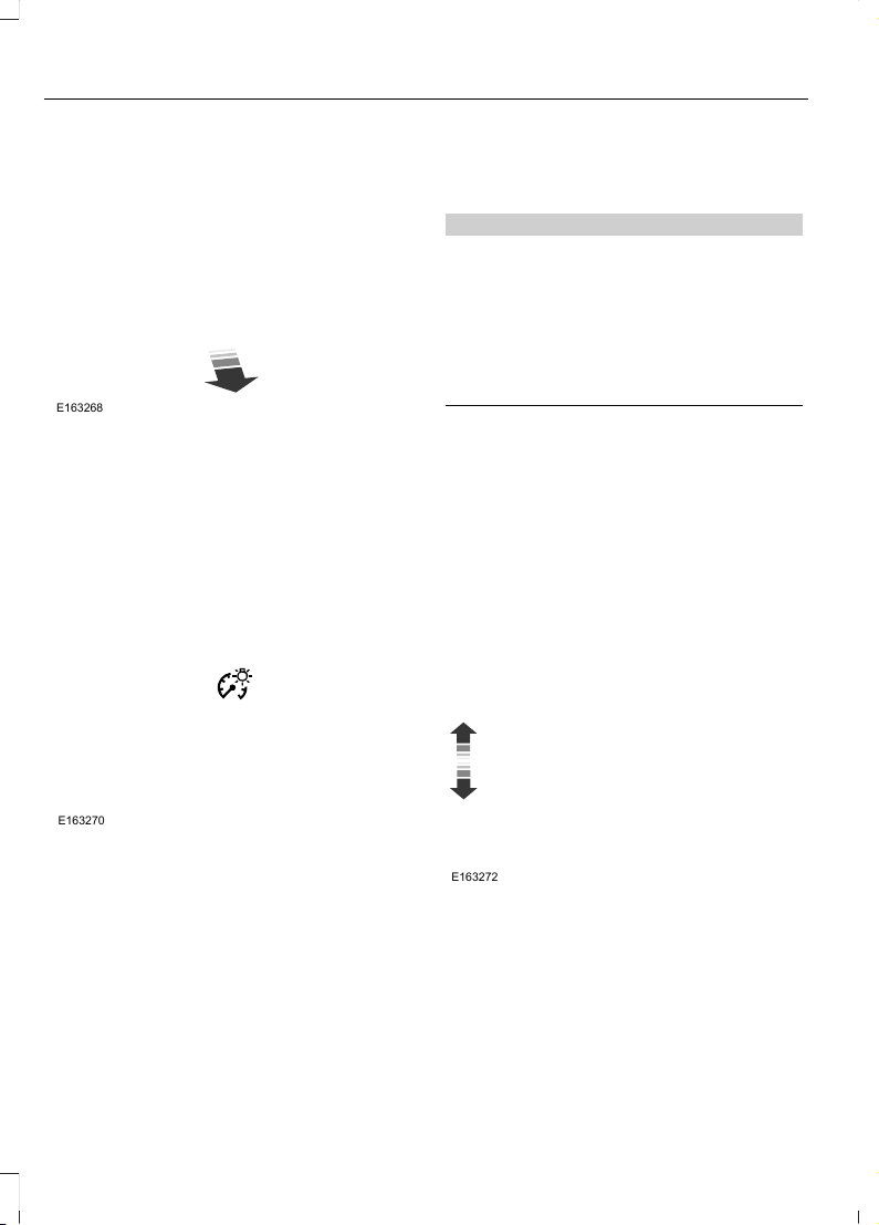
Headlamp Flasher
E163268
Pull the lever toward you to flash the
headlamps and release the lever to switch
the headlamps off.
INSTRUMENT LIGHTING DIMMER
E163270
Use to adjust the brightness of the
instrument panel and all applicable lit
components in the vehicle during
headlamp and parking lamp operation.
• Tap the top or bottom of the control
to brighten or dim all interior lit
components incrementally.
• Press and hold at the first position of
the top or bottom of the control until
you reach the desired lighting level.
DAYTIME RUNNING LAMPS (If
Equipped)
WARNING
Always remember to switch your
headlamps on in low light situations
or during inclement weather. The
system does not activate the tail lamps
and may not provide adequate lighting
during these conditions. Failure to activate
your headlamps under these conditions
may result in a collision.
The system turns on the headlamps with
a reduced output in daylight conditions.
To switch the system on:
1. Switch on the ignition.
2. Switch the lighting control to the off or
parking lamp position.
DIRECTION INDICATORS
E163272
• To operate the left direction indicator,
push the lever down.
• To operate the right direction indicator,
push the lever up.
• To cancel direction indicator operation
manually, push the lever again in the
opposite direction.
48
F650750 (TBC), enUSA, First Printing
Lighting
Page 52
If your vehicle is a tractor, the direction
indicators may not shut off when you
complete a turn. This is normal. Contact
an authorized dealer if there are any
questions about your vehicle’s options.
INTERIOR LAMPS
Map Lamps
The map lamps are located on the
overhead console. Press the controls on
either side of each map lamp to switch on
the lamps. The map lamps also light when:
• You open any door.
• You press any of the remote entry
controls when the ignition is off.
E163273
Dome and Map Lamps
E163274
Press the switches on either side of the
dome lamp to switch on the lamps. The
map lamps also light when:
• You open any door.
• You press any of the remote entry
controls when the ignition is off.
49
F650750 (TBC), enUSA, First Printing
Lighting
Page 53
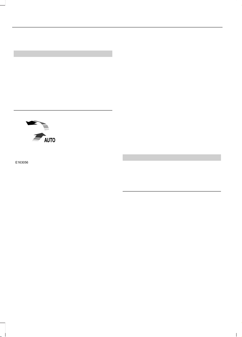
POWER WINDOWS (If Equipped)
WARNINGS
Do not leave children unattended in
your vehicle and do not let them play
with the power windows. They may
seriously injure themselves.
When closing the power windows,
you should verify they are free of
obstructions and make sure that
children and pets are not in the proximity
of the window openings.
E163056
Note: You may hear a pulsing noise when
just one of the windows is open. Lower the
opposite window slightly to reduce this
noise.
Press the switch to open the window.
Lift the switch to close the window.
One-Touch Up or Down (If Equipped)
Press or lift the switch fully and release it.
Press or lift it again to stop the window.
Note: The window may disable for up to
five minutes if you cycle it up and down
repeatedly. This helps prevent damage to
the motor. Normal operation resumes once
the motor cools.
Restoring the One-Touch Up Function
You may lose the one-touch function if the
vehicle battery is low.
Note: Perform one-touch up re-calibration
with the door closed. Calibrating with the
door open causes the window to bounce
back continuously.
To reset the function after the battery
recharges:
1. Pull the switch all the way up.
2. Hold the switch until the glass stops
and continue to hold for two seconds.
3. Press the switch down and operate the
window to the full down position.
One-touch up is now functional.
Bounce-Back (If Equipped)
The window stops automatically while
closing. It reverses some distance if there
is an obstacle in the way.
Overriding the Bounce-Back Feature
WARNING
When you override the bounce-back
feature, the window will not reverse
if it detects an obstacle. Take care
when closing the windows to avoid
personal injury or damage to your vehicle.
Pull up the window switch and hold within
two seconds of the window reaching the
bounce-back position. The window travels
up with no bounce-back protection. The
window stops if you release the switch
before the window closes fully.
Window Lock (If Equipped)
Press the control to lock or unlock the rear
window controls.
50
F650750 (TBC), enUSA, First Printing
Windows and Mirrors
Page 54
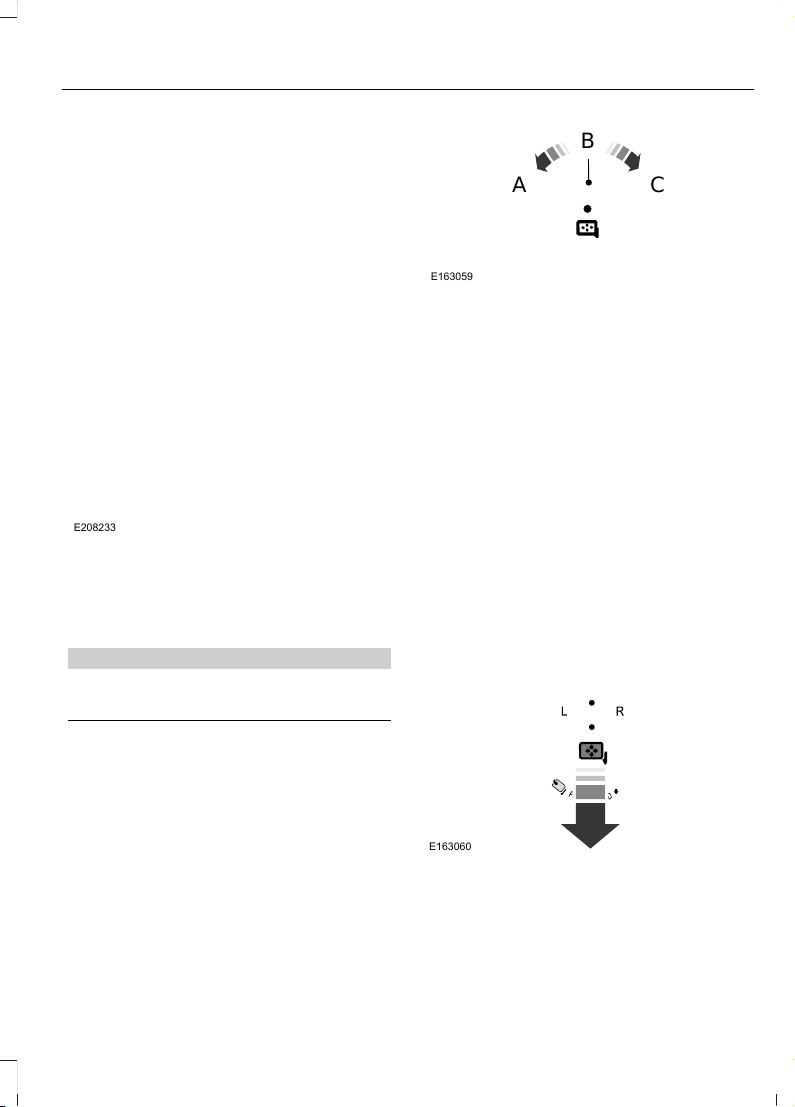
EXTERIOR MIRRORS
Auxiliary Convex Mirrors
E208233
Convex mirrors are a ball-stud design for
precise adjustment to maximize viewing
area.
Power Exterior Mirrors (If Equipped)
WARNING
Do not adjust the mirrors when your
vehicle is moving.
E163059
B
A
C
Left–hand mirror.A
Off.B
Right–hand mirror.C
To adjust a mirror:
1. Rotate the control to select the mirror
you want to adjust.
2. Adjust the position of the mirror.
3. Return the control to the center
position to lock mirrors in place.
Foldaway Exterior Mirrors
For tight parking conditions, you can push
the mirror toward the door window glass.
Before driving, make sure that you fully
engage the mirror in its support when
returning it to its original position.
Power–Folding Mirrors (If Equipped)
E163060
1. Rotate the control so the dots line up.
2. Pull the control back to fold the mirrors
in or out.
51
F650750 (TBC), enUSA, First Printing
Windows and Mirrors
Page 55
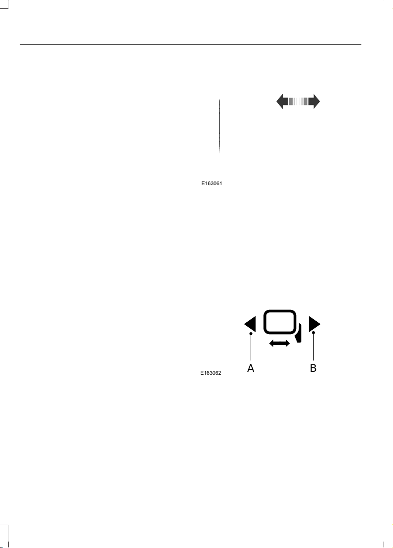
Note: If you repeatedly fold and unfold the
mirrors several times within one minute, the
system may disable to protect the motors
from overheating. It resets to normal
function automatically within three to five
minutes.
You can also fold a mirror manually by
pushing it toward the door window glass.
After you manually adjust the mirror, you
need to reset it.
To reset the power–folding mirror system
and return it to its normal function:
• Fold the mirror manually by pushing it
toward the door window glass.
• Use the power–fold control to fold and
unfold the mirror two or three times.
The mirror makes a sound as it resets.
Heated Exterior Mirrors (If Equipped)
See Heated Exterior Mirrors (page 72).
Signal Indicator Mirrors (If Equipped)
The outer portion of the appropriate mirror
housing blinks when you use the direction
indicator.
Clearance Lamps (If Equipped)
The lower, outer part of the mirror housings
light when you switch on the headlamps
or parking lamps.
Telescoping Mirrors (If Equipped)
E163061
This feature lets you extend the mirror
about 3 in (76 mm). It is useful when
towing a trailer. You can manually pull out
or push in the mirrors to the desired
position.
PowerScope™ Power Telescoping
Mirrors (If Equipped)
This feature lets you position both mirrors
in or out at the same time. The control is
on the door trim panel.
E163062
BA
Telescope out.A
Telescope in.B
52
F650750 (TBC), enUSA, First Printing
Windows and Mirrors
Page 56

To adjust the mirrors:
• Press and hold the control.
• When you position the mirrors in or out,
the motors run as long as you hold the
control. The running motors allow you
to make adjustments as needed.
• After positioning the mirrors, return the
control to the center position to help
protect the motors from overheating.
INTERIOR MIRROR
WARNING
Do not adjust the mirror when your
vehicle is moving.
Note: Do not clean the housing or glass of
any mirror with harsh abrasives, fuel or other
petroleum or ammonia-based cleaning
products
You can adjust the interior mirror to your
preference. Some mirrors also have a
second pivot point. This lets you move the
mirror head up or down and from side to
side.
Pull the tab below the mirror toward you
to reduce glare at night.
SUN VISORS
Slide-on-rod (If Equipped)
E138666
Rotate the sun visor toward the side
window and extend it rearward for extra
shade.
53
F650750 (TBC), enUSA, First Printing
Windows and Mirrors
Page 57
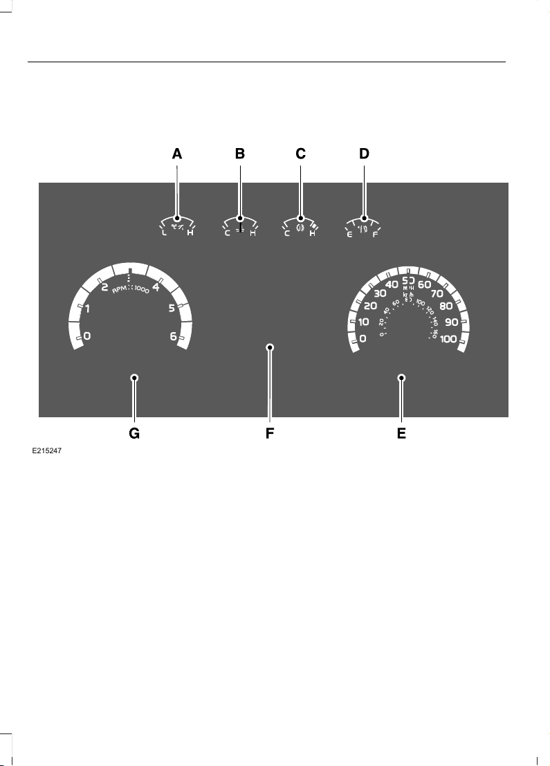
GAUGES
Gasoline Engines
E215247
Engine oil pressure gauge.A
Engine coolant temperature gauge.B
Transmission fluid temperature gauge.C
Fuel gauge.D
Speedometer.E
Information display.F
Tachometer.G
54
F650750 (TBC), enUSA, First Printing
Instrument Cluster
Page 58

Engine Oil Pressure Gauge
Indicates engine oil pressure. The needle
should stay in the normal operating range
(between L and H). If the needle falls
below the normal range, stop the vehicle,
switch off the engine and check the engine
oil level. Add oil if needed. If the oil level is
correct, have your vehicle checked by an
authorized dealer.
Engine Coolant Temperature
Gauge
WARNING
Never remove the coolant reservoir
cap while the engine is running or hot.
Indicates engine coolant temperature. At
normal operating temperature, the level
indicator is in the normal range. If the
engine coolant temperature exceeds the
normal range, stop the vehicle as soon as
safely possible, switch off the engine and
let the engine cool.
Transmission Fluid Temperature
Gauge
Indicates transmission fluid temperature.
At normal operating temperature, the level
indicator is in the normal range. If the
transmission fluid temperature exceeds
the normal range, stop the vehicle as soon
as safely possible and verify the airflow is
not restricted such as snow or debris
blocking airflow through the grille.
Special operating conditions, such as
snowplowing, towing or off-road use, can
cause higher than normal operating
temperatures. See Special Operating
Conditions Scheduled Maintenance
(page 326).
Operating the transmission for extended
periods with the gauge in the higher than
normal area may cause internal
transmission damage. We recommend
altering the severity of the driving
conditions to lower the transmission
temperature into the normal range. If the
gauge continues to show high
temperatures, contact an authorized
dealer.
Fuel Gauge
Note: The fuel gauge may vary slightly
when your vehicle is moving or on a gradient.
Switch the ignition on. The fuel gauge
indicates approximately how much fuel is
in the fuel tank. The arrow adjacent to the
fuel pump symbol indicates on which side
of your vehicle the fuel filler door is located.
The needle should move toward F when
you refuel your vehicle. If the needle points
to E after adding fuel, this indicates your
vehicle needs service soon.
After refueling, some variability in needle
position is normal:
• It may take a short time for the needle
to reach F after leaving the gas station.
This is normal and depends upon the
slope of pavement at the gas station.
• The fuel amount dispensed into the
tank is a little less or more than the
gauge indicated. This is normal and
depends upon the slope of pavement
at the gas station.
• If the gas station nozzle shuts off
before the tank is full, try a different
gas pump nozzle.
Gauge Package (If Equipped)
If your vehicle is equipped with the optional
gauge package, it has some or all of the
following gauges:
55
F650750 (TBC), enUSA, First Printing
Instrument Cluster
Page 59
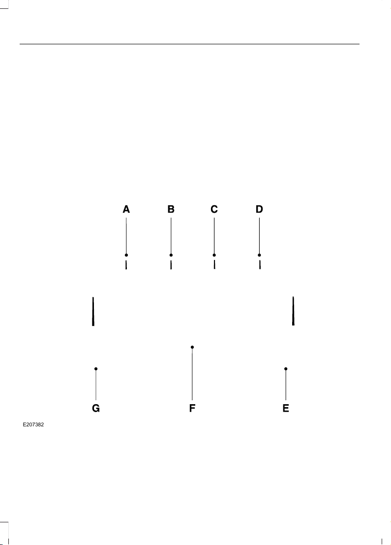
• Transmission temperature gauge:
Displays the transmission fluid
temperature at the transmission sump.
• Hourmeter: Displays the hours of
engine run time.
• Voltmeter: Displays electrical system
voltage.
Information Display
Odometer
Located in the bottom of the information
display. Registers the accumulated
distance your vehicle has traveled.
Trip Computer
See General Information (page 62).
Vehicle Settings and Personalization
See General Information (page 62).
Diesel Engines
E207382
Engine oil pressure gauge.A
Engine coolant temperature gauge.B
Diesel Exhaust Fluid (DEF) gauge.C
56
F650750 (TBC), enUSA, First Printing
Instrument Cluster
Page 60

Fuel gauge.D
Speedometer.E
Information display.F
Tachometer.G
Engine Oil Pressure Gauge
Indicates engine oil pressure. The needle
should stay in the normal operating range
(between L and H). If the needle falls
below the normal range, stop the vehicle,
switch off the engine and check the engine
oil level. Add oil if needed. If the oil level is
correct, have your vehicle checked by an
authorized dealer.
Engine Coolant Temperature
Gauge
WARNING
Never remove the coolant reservoir
cap while the engine is running or hot.
Indicates engine coolant temperature. At
normal operating temperature, the level
indicator is in the normal range. If the
engine coolant temperature exceeds the
normal range, stop the vehicle as soon as
safely possible, switch off the engine and
let the engine cool.
Diesel Exhaust Fluid (DEF) Gauge
Indicates the fluid level in the DEF tank.
Fuel Gauge
Note: The fuel gauge may vary slightly
when your vehicle is moving or on a gradient.
Switch the ignition on. The fuel gauge
indicates approximately how much fuel is
in the fuel tank. The arrow adjacent to the
fuel pump symbol indicates on which side
of your vehicle the fuel filler door is located.
The needle should move toward F when
you refuel your vehicle. If the needle points
to E after adding fuel, this indicates your
vehicle needs service soon.
After refueling, some variability in needle
position is normal:
• It may take a short time for the needle
to reach F after leaving the gas station.
This is normal and depends upon the
slope of pavement at the gas station.
• The fuel amount dispensed into the
tank is a little less or more than the
gauge indicated. This is normal and
depends upon the slope of pavement
at the gas station.
• If the gas station nozzle shuts off
before the tank is full, try a different
gas pump nozzle.
Gauge Package (If Equipped)
If your vehicle is equipped with the optional
gauge package, it has some or all of the
following gauges:
• Transmission temperature gauge:
Displays the transmission fluid
temperature at the transmission sump.
• Hourmeter: Displays the hours of
engine run time.
• Voltmeter: Displays electrical system
voltage.
Information Display
Odometer
Located in the bottom of the information
display. Registers the accumulated
distance your vehicle has traveled.
57
F650750 (TBC), enUSA, First Printing
Instrument Cluster
Page 61
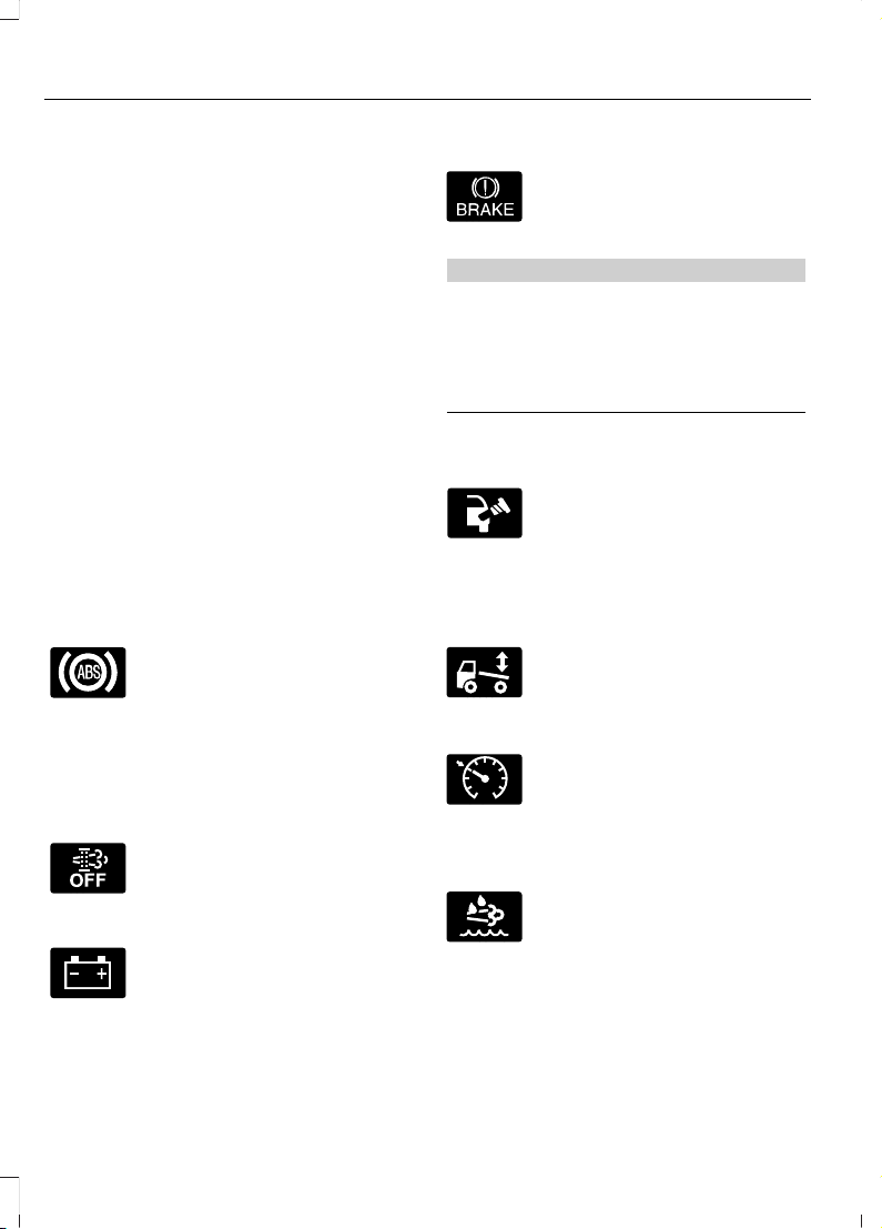
Trip Computer
See General Information (page 62).
Vehicle Settings and Personalization
See General Information (page 62).
WARNING LAMPS AND INDICATORS
The following warning lamps and
indicators alert you to a vehicle condition
that may become serious. Some lamps
illuminate when you start your vehicle to
make sure they work. If any lamps remain
on after starting your vehicle, refer to the
respective system warning lamp for further
information.
Note: Some warning indicators appear in
the information display and function the
same as a warning lamp but do not display
when you start your vehicle.
Anti-Lock Braking System
If it illuminates when you are
driving, this indicates a
malfunction. You continue to
have the normal braking system (without
ABS) unless the brake system warning
lamp is also illuminated. Have the system
checked by an authorized dealer.
Automatic Regeneration Control
Illuminates when you switch it
off.
Battery
If it illuminates while driving, it
indicates a malfunction. Switch
off all unnecessary electrical
equipment and have the system checked
by an authorized dealer immediately.
Brake System
Indicates low brake fluid level or
a brake system malfunction.
Have the system checked
immediately by an authorized dealer.
WARNING
Driving your vehicle with the warning
lamp on is dangerous. A significant
decrease in braking performance
may occur. It will take you longer to stop
your vehicle. Have your vehicle checked by
your authorized dealer immediately.
Check Fuel Cap (Gasoline Engine
Only)
Illuminates when you may not
have properly installed the fuel
cap. Continued driving with this
light on may cause the Service engine soon
warning indicator to come on.
Check Suspension (If Equipped)
Illuminates when you press the
air suspension dump switch.
Cruise Control (If Equipped)
E71340
Illuminates when you switch on
this feature. See Using Cruise
Control (page 134).
Diesel Exhaust Fluid (Diesel
Engine Only)
Illuminates with the key in the
ON position, when the fluid is
contaminated or the level falls
below 1.0 gal (3.8 L). Refill the tank or, at
a minimum, add at least 1.0 gal (3.8 L) in
the tank.
58
F650750 (TBC), enUSA, First Printing
Instrument Cluster
Page 62
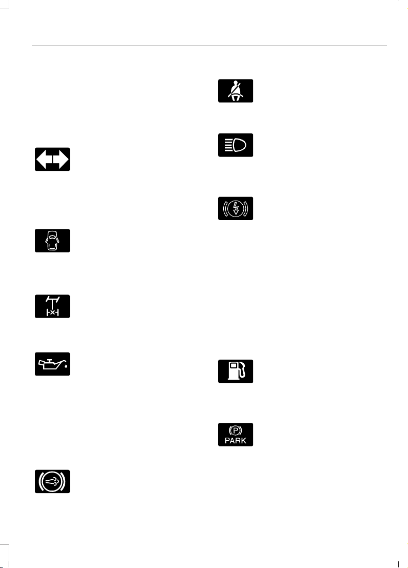
Diesel Particulate Filter (Diesel
Engine Only)
Illuminates when the soot level in the
diesel particulate filter has reached a point
where it requires operator assistance. See
Diesel Particulate Filter (page 87).
Direction Indicator
Illuminates when you switch on
the left or right direction
indicator or when you switch on
the hazard warning flashers. If the
indicators stay on or flash faster, check for
a burned out bulb.
Door Ajar
Displays when the ignition is on
and any door is not completely
closed.
Electronic Locking Differential (If
Equipped)
Illuminates when using the
electronic locking differential.
Engine Oil Pressure (Gasoline
Engine Only)
If it illuminates with the engine
running, or when you are driving,
this indicates a malfunction.
Stop your vehicle as soon as it is safe to
do so and switch off the engine. Check the
engine oil level.
Note: Do not resume your journey if it
illuminates despite the level being correct.
Have the system checked by an authorized
dealer immediately.
Exhaust Brake On
E171217
The exhaust brake indicator light
illuminates when you switch the
exhaust brake on.
Fasten Safety Belt
Illuminates and a tone sounds
to remind you to fasten your
safety belt.
High Beam
Illuminates when you switch on
the high beam headlamps. It
flashes when you use the
headlamp flasher.
Hydromax
E146190
Illuminates to indicate normal
hydromax booster reserve
system activation when the
engine is off and the service brake pedal is
applied. This light may also illuminate
momentarily if the engine is running and
the driver turns the steering wheel fully in
one direction while braking. If the light
remains on while the engine is running, this
indicates inadequate hydraulic booster
pressure or reserve pump system failure.
Stop the vehicle as soon as possible and
seek service immediately by your
authorized dealer.
Low Fuel Level (Gasoline Engine
Only)
Illuminates when the fuel level
is low or the fuel tank is nearly
empty. Refuel as soon as
possible.
Parking Brake Warning
E208810
Illuminates briefly when you
switch the ignition to the on
position (with the engine off). It
also illuminates when you apply the
parking brake. If the park brake lamp does
not illuminate at these times, seek service
immediately. Vehicles equipped with the
power park parking brake option: If the park
59
F650750 (TBC), enUSA, First Printing
Instrument Cluster
Page 63
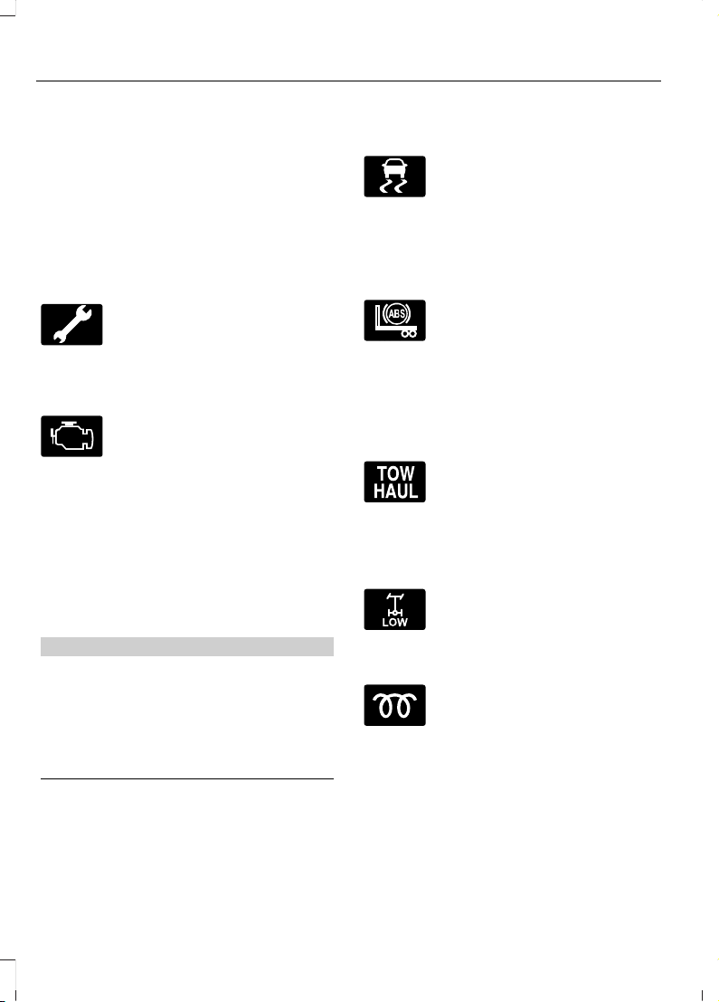
brake warning lamp begins to blink after
setting the parking brake, this may indicate
a failure in the parking brake system. Seek
service from an authorized dealer
immediately. Driving extended distances
with the parking brake engaged can cause
brake failure and the risk of personal injury.
Powertrain Malfunction/Reduced
Power/Electronic Throttle Control
(Gasoline Engine Only)
Illuminates in the event of a
powertrain fault. Contact an
authorized dealer as soon as
possible.
Service Engine Soon
The service engine soon
indicator light illuminates when
you first switch on the ignition,
before starting the engine, to check the
bulb and to indicate whether the vehicle
is ready for Inspection/Maintenance (I/M)
testing.
If the service engine soon indicator light
stays illuminated after you start the engine,
it indicates that the On-Board Diagnostics
(OBD-II) system has detected a
malfunction of the vehicle emissions
control system.
WARNING
Under engine misfire conditions,
excessive exhaust temperatures
could damage the catalytic
converter, the fuel system, interior floor
coverings or other vehicle components,
possibly causing a fire. Have an authorized
dealer service your vehicle immediately.
Traction Control (Diesel Engine
Only)
E138639
Illuminates and flashes slowly if
you select the Off Road or
Mud/Snow mode. It illuminates
and flashes rapidly during a traction
control event.
Trailer Anti-Lock Brake System
(ABS)
Illuminates briefly when you
switch on the ignition, and only
when a PLC trailer or a PLC
diagnostic tool is connected. If the light
fails to illuminate, remains on after you
start the vehicle or continues to flash, have
the system serviced immediately.
Transmission Tow/Haul (If Equipped)
Illuminates when you switch on
the tow/haul feature. If the light
flashes steadily, have the system
serviced immediately, damage to the
transmission could occur.
Two Speed Axle
The Two Speed Axle indicator
comes on when you switch the
low axle range on.
Wait to Start (Diesel Engine Only)
Illuminates when you switch the
ignition on as part of the
pre-start system. Wait until the
wait to start indicator turns off before
attempting to start vehicle.
60
F650750 (TBC), enUSA, First Printing
Instrument Cluster
Page 64
WARNING
If equipped with an air intake heater,
DO NOT use ether or any other
starting fluids. The use of starting
fluids (ether) in an engine equipped with
an air intake heater could result in damage
and/or personal injury.
Water in Fuel (Diesel Engine Only)
Illuminates when the fuel
filter/water separator has a
significant quantity of water in
it.
If the light illuminates when the engine is
running, stop the vehicle as soon as safely
possible, shut off the engine, then drain the
fuel filter/water separator.
Allowing water to stay in the system could
result in extensive damage to, or failure of,
the fuel injection system.
WARNING
Do not drain the water separator
while the engine is running. Fuel may
ignite if the separator is drained while
the engine is running or the vehicle is
moving.
AUDIBLE WARNINGS AND INDICATORS
Headlamps On Warning Chime
Sounds when you remove the key from the
ignition and open the driver's door and you
have left the headlamps or parking lamps
on.
Key in Ignition Warning Chime
Sounds when you open the driver's door
and you have left the key in the ignition
with it in the off or accessory position.
61
F650750 (TBC), enUSA, First Printing
Instrument Cluster
Page 65
GENERAL INFORMATION
WARNING
Driving while distracted can result in
loss of vehicle control, crash and
injury. We strongly recommend that
you use extreme caution when using any
device that may take your focus off the
road. Your primary responsibility is the safe
operation of your vehicle. We recommend
against the use of any hand-held device
while driving and encourage the use of
voice-operated systems when possible.
Make sure you are aware of all applicable
local laws that may affect the use of
electronic devices while driving.
You can control various systems on your
vehicle using the information display
controls on the steering wheel. The
information display provides the
corresponding information.
Information Display Controls
• Press the INFO button to scroll through
trip, outside temperature and fuel
usage information.
• Press the SETUP button to scroll
through various vehicle feature
settings.
• Press the RESET button to choose
settings, reset information and confirm
messages.
Info
Press the INFO button repeatedly to cycle
through the following features:
Note: Some options may appear slightly
different or not at all if the items are
optional.
INFO
TRIP A
TRIP B
XXX MILES (km) TO E
XX.X AVG MPG (L/100km)
MPG (L/km)
TIMER
EXHAUST FILTER
*
TRANS TEMP
BLANK SCREEN
*
Diesel engine only.
62
F650750 (TBC), enUSA, First Printing
Information Displays
Page 66
TRIP A/B
Registers the distance of individual
journeys. Press and release the INFO
button until TRIP A/B appears in the
display (this represents the trip mode).
Press and hold the RESET button to reset.
XXX MILES (km) TO E
This displays an estimate of approximately
how far you can drive with the fuel
remaining in your tank under normal driving
conditions. Remember to turn the ignition
off when refueling to allow this feature to
detect the correct amount of added fuel.
The system calculates the distance to
empty by using a running average fuel
economy, which uses your recent driving
history of 500 miles (800 km).
This value is not the same as the average
fuel economy display. The running average
fuel economy resets to a factory default
value if the battery is disconnected.
XX.X AVG MPG (L/100km)
Average fuel economy displays your
average fuel economy in miles per gallon
or liters/100 km.
MPG (L/km)
Displays the instantaneous fuel economy
as a bar graph. Your vehicle must be
moving to calculate instantaneous fuel
economy. You cannot reset the
instantaneous fuel economy.
TIMER
Displays the trip elapsed drive time. Press
and release RESET to pause the timer.
Press and hold RESET to reset the timer.
EXHAUST FILTER
Displays information about the status of
the exhaust filter.
System Check and Vehicle Feature
Customization
Press the SETUP button repeatedly to
cycle the information display through the
following features:
Note: Some options may appear slightly
different or not at all if the items are
optional.
Note: When returning to the SETUP menu
and you selected a non-English language,
HOLD RESET FOR ENGLISH displays to
change back to English. Press and hold the
RESET button to change back to English.
SETUP
OIL LIFEPress the RESET buttonRESET FOR SYSTEM
CHECK
ENGINE HOURS
DEF LEVEL
*
All DOORS CLOSED
CHECK BRAKE SYSTEM
HOLD RESET = NEWOIL LIFE
English or MetricUNITS
63
F650750 (TBC), enUSA, First Printing
Information Displays
Page 67

SETUP
ON or OFFAUTO LOCK
ON or OFFAUTO UNLOCK
ON or OFFCOURTESY WIPE
ON or OFFREMOTE WINDOW
ENGLISH / SPANISH / FRENCHLANGUAGE
*
Diesel engine only.
PRESS RESET FOR SYSTEM CHECK
The information display begins to cycle
through the vehicle systems and provides
a status of the item if needed.
Note: Some systems show a message only
if a condition is present.
OIL LIFE
Displays the remaining oil life. An oil
change is required whenever indicated by
the information display and according to
the recommended maintenance schedule.
Only use recommended engine oils.
To reset the oil monitoring system to 100%
after each oil change, perform the
following:
1. Press and release the SETUP button
to display OIL LIFE XXX% HOLD RESET
= NEW.
2. Press and hold the RESET button for
two seconds and release to reset the
oil life to 100%.
Note: To change oil life 100% value (if
equipped with this feature) to another value,
proceed to Step 3.
3. Once OIL LIFE SET TO XXX% is
displayed, release and press the RESET
button to change the Oil Life Start
Value. Each release and press reduces
the value by 10%.
UNITS
Displays the current units English or Metric.
LANGUAGE = ENGLISH / SPANISH /
FRENCH
Allows you to choose which language the
message center displays.
Waiting four seconds or pressing the
RESET button cycles the message center
through each of the language choices.
Press the RESET button to set the
language choice.
INFORMATION MESSAGES
Note: Depending on your vehicle options
and instrument cluster type, not all of the
messages display or are available.
Additionally, the information display may
abbreviate or shorten certain messages.
Press the RESET button to acknowledge
and remove some messages from the
information display. The information
display automatically removes other
messages after a short time.
You need to confirm certain messages
before you can access the menus.
64
F650750 (TBC), enUSA, First Printing
Information Displays
Page 68

Diesel Messages
WARNING
When the CLEANING EXHAUST
FILTER message appears in the
information display, do not park near
flammable materials, vapors or structures
until filter cleaning is complete.
ActionMessage
The coolant additive needs checking.CHECK COOLANT
ADDITIVE
Your vehicle has entered the cleaning mode. Various engine
actions raise the exhaust temperature in the diesel particulate
filter system to burn off the particles (exhaust soot). After
the vehicle burns off the particles, the exhaust temperature
returns to normal levels. This message is normal.
CLEANING EXHAUST
FILTER
The diesel particulate filter is full of particles (exhaust soot)
and you are not operating the vehicle in a manner that allows
normal cleaning. One of these messages stays on until the
exhaust filter cleaning has begun, at which time the CLEANING
EXHAUST FILTER message displays. We recommend you
drive the vehicle above 30 mph (48 km/h) until the CLEANING
EXHAUST FILTER message turns off.
EXHAUST OVER-
LOADED DRIVE TO
CLEAN
EXHAUST AT LIMIT
DRIVE TO CLEAN NOW
The diesel particulate filter continues to fill with particles
(exhaust soot) if you ignore this message. The service engine
soon light illuminates and engine power may be limited, if
cleaning is not permitted. Your vehicle requires dealer service
to restore it to full–power operation.
Your vehicle exhaust system temperature exceeds intended
operating range. If this warning occurs, a chime sounds,
followed by reduced engine power. The engine shuts down
when your vehicle speed is below 3 mph (5 km/h). Stop the
vehicle as soon as safely possible. Have the system checked
by an authorized dealer.
STOP SAFELY NOW
The diluted engine oil needs to be changed.ENGINE OIL DILUTED
Your vehicle will have reduced engine torque until the engine
is warmed sufficiently.
ENGINE WARMING
REDUCED POWER
The powertrain control module intentionally turns the engine
off due to your vehicle being in the final 30 seconds of a
countdown. The diesel engine shutdown for extended idling
is an optional feature.
ENGINE TURNS OFF IN
XX SECONDS
Appears after the 30–second countdown.ENGINE TURNED OFF
65
F650750 (TBC), enUSA, First Printing
Information Displays
Page 69
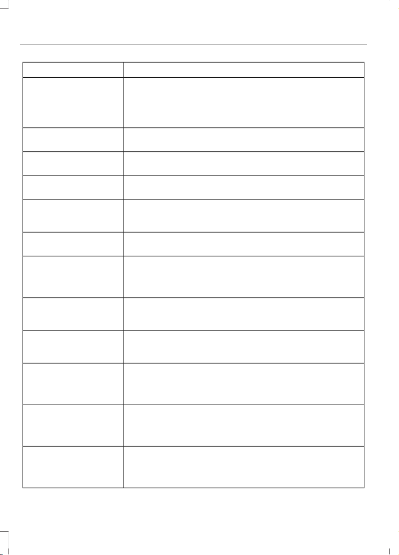
ActionMessage
In extremely cold weather, typically below -15°F (-26°C) and
if the engine block heater is not utilized, your engine does not
respond to accelerator pedal movement for 30 seconds. This
restriction allows your engine to circulate the oil properly in
order to avoid engine damage.
ENGINE WARMING
PLEASE WAIT
Your diesel particulate filter is clean.EXHAUST FILTER DRIVE
COMPLETE
Your diesel particulate filter is clean.EXHAUST FILTER
CLEANED
The manual operator commanded regeneration process has
stopped.
EXHAUST CLEAN
STOPPED
Your message center may report a DPF loading of 50% or
greater on initial delivery or following service DPF re-set, this
is normal.
DPF LOADING OF 50%
OR GREATER
The distance you can travel before depleting the remaining
diesel exhaust fluid.
EXHAUST FLUID RANGE
XXX MI
Your diesel exhaust fluid is nearing empty. Your vehicle’s top
speed becomes limited in the displayed distance. You must
replenish the diesel exhaust fluid to resume normal operation
of your vehicle.
IN XX MILES, SPEED
LIMITED TO XX MPH
EXHAUST FLUID EMPTY
Your remaining diesel exhaust fluid has depleted. Your speed
is limited upon restart. You must replenish the diesel exhaust
fluid to resume normal operation of your vehicle.
SPEED LIMITED TO XX
MPH UPON RESTART
EXHAUST FLUID EMPTY
The diesel exhaust fluid is empty. You must replenish the
diesel exhaust fluid to resume normal operation of your
vehicle.
SPEED LIMITED TO XX
MPH EXHAUST FLUID
EMPTY
The selective catalytic reduction system detects low exhaust
fluid. The engine eventually enters into an idle–only mode.
You must replenish the diesel exhaust fluid to resume normal
operation of your vehicle.
ENGINE IDLED SOON
EXHAUST FLUID EMPTY
A problem exists with the selective catalytic reduction system.
The vehicle enters into an idle–only mode. If the exhaust fluid
is empty, you must replenish the diesel exhaust fluid to resume
normal operation of your vehicle.
ENGINE IDLED - SEE
OWNER’S MANUAL
EXHAUST FLUID EMPTY
The selective catalytic reduction system detects a fault. The
vehicle’ s top speed becomes limited in the displayed distance
starting at 50 mi (80 km) and count down from this point.
Have the system checked by an authorized dealer.
IN XX MILES, SPEED
LIMITED TO 50 MPH
EXHAUST FLUID
SYSTEM FAULT
66
F650750 (TBC), enUSA, First Printing
Information Displays
Page 70

ActionMessage
The selective catalytic reduction system detects a fault. The
vehicle’s top speed becomes limited upon restarting. Have
the system checked by an authorized dealer.
SPEED LIMITED TO 50
MPH UPON RESTART
EXHAUST FLUID
SYSTEM FAULT
The selective catalytic reduction system detects a fault. The
vehicle’s top speed is limited. Have the system checked by
an authorized dealer.
SPEED LIMITED TO 50
MPH EXHAUST FLUID
SYSTEM FAULT
The selective catalytic reduction system detects a fault. The
engine enters into an idle–only mode. Have the system
checked by an authorized dealer.
ENGINE IDLED SOON
EXHAUST FLUID
SYSTEM FAULT SEE
MANUAL
The selective catalytic reduction system detects a fault. The
engine eventually enters into an idle–only mode. Press OK to
override the idle mode. Have the system checked by an
authorized dealer.
ENGINE IDLED - SEE
OWNER’S MANUAL
EXHAUST FLUID
SYSTEM FAULT
A fuel filter change is required.FUEL FILTER CHANGE
REQUIRED
You must have your vehicle serviced by an authorized dealer
if approximately two hours after the EXHAUST OVERLOADED
DRIVE TO CLEAN message has displayed and you have not
driven your vehicle above 30 mph (48 km/h) for at least 20
minutes to clean the diesel particulate filter.
EXHAUST OVER LIMIT
SERVICE NOW
You are responsible for assuring that you operate your vehicle
in a manner that allows diesel particulate filter cleaning to
occur. Ignoring the EXHAUST OVER LIMIT SERVICE NOW
warning message could lead to reduced drivability and
customer expense, including damage to the diesel particulate
filter. Your new vehicle warranty may not cover this damage.
The water separator has reached a predetermined capacity
and needs draining.
WATER IN FUEL DRAIN
FILTER SEE MANUAL
A low fuel pressure condition has occurred due to cold, low
fuel level or fuel filters need to be changed.
LOW FUEL PRESSURE
67
F650750 (TBC), enUSA, First Printing
Information Displays
Page 71
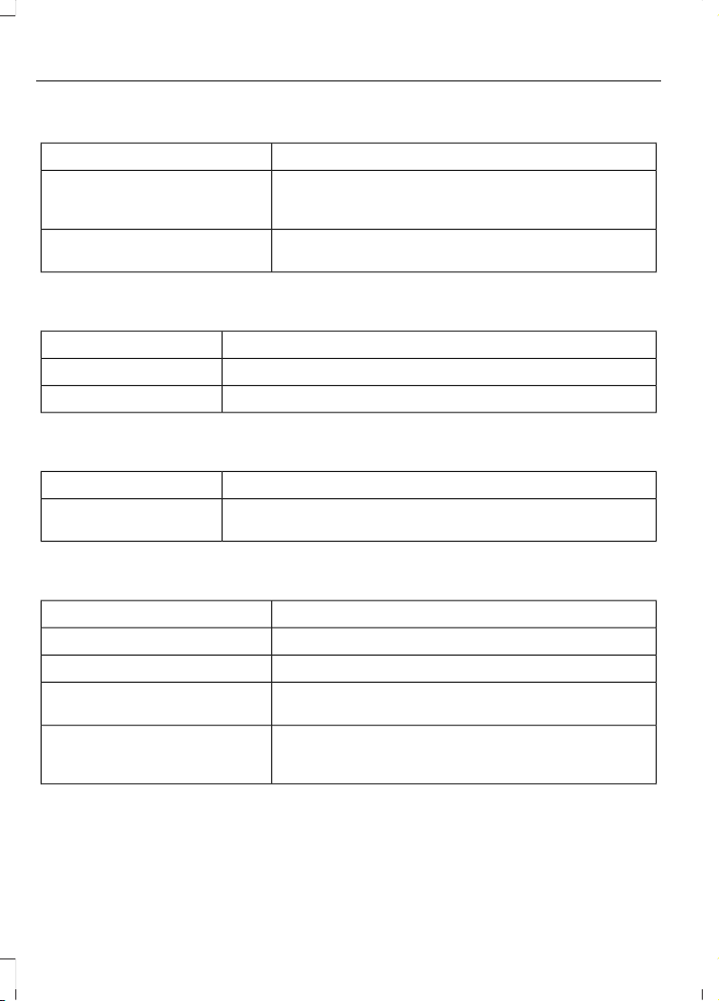
Engine
ActionMessage
Your vehicle is set to transport mode. The transport
mode disables certain vehicle functions to prevent
battery discharge.
TRANSPORT MODE CONTACT
DEALER
The vehicle has reduced engine speed because fluid
temperatures are at or near their max operating limits.
POWER REDUCED TO LOWER
ENGINE TEMP
Fuel
ActionMessage
An early reminder of a low fuel condition.FUEL LEVEL LOW
The fuel cap may not be properly closed.CHECK FUEL CAP
Key
ActionMessage
The factory equipped remote start is active. Turn your key to
on to drive.
TO DRIVE: TURN KEY
TO ON
Maintenance
ActionMessage
The engine oil life is nearing its end.ENGINE OIL CHANGE SOON
The oil life left reaches 0%.OIL CHANGE REQUIRED
The brake fluid level is low and the brake system needs
inspection immediately.
BRAKE FLUID LEVEL LOW
The brake system needs servicing. If the warning stays
on or continues to come on, have the system checked
by an authorized dealer as soon as possible.
CHECK BRAKE SYSTEM
68
F650750 (TBC), enUSA, First Printing
Information Displays
Page 72

Park Brake
ActionMessage
The parking brake is set and your vehicle is in motion.PARK BRAKE ENGAGED
69
F650750 (TBC), enUSA, First Printing
Information Displays
Page 73
MANUAL CLIMATE CONTROL
E214636
Defrost: Select to distribute air through the windshield air vents. Air distribution
to the instrument panel and footwell vents turns off. You can also use this
setting to defrost and clear the windshield of a thin covering of ice.
A
Heated mirrors: Press the button to switch the heated exterior mirrors on and
off. See Heated Exterior Mirrors (page 72).
B
Air distribution control: Adjust the control to turn airflow from the windshield,
instrument panel, or footwell vents on or off. You can distribute air through the
following combinations: windshield, windshield/floor, panel, panel/floor, and
floor.
C
A/C: Press the button to switch the air conditioning on or off. Air conditioning
cools your vehicle using outside air. To improve the time to reach a comfortable
temperature in hot weather, drive with the windows open until you feel cold air
through the air vents.
D
Recirculated air: Press the button to switch between outside air and
recirculated air. The air currently in the passenger compartment recirculates.
This can reduce the time needed to cool the interior and reduce unwanted odors
from entering your vehicle.
E
Note: Recirculated air may also turn on and off automatically in instrument
panel or instrument panel and floor airflow modes during hot weather to improve
cooling efficiency.
70
F650750 (TBC), enUSA, First Printing
Climate Control
Page 74

MAX A/C: Adjust the control for maximum cooling. Recirculated air flows
through the instrument panel vents, air conditioning automatically turns on and
the fan automatically adjusts to the highest speed.
F
Temperature control: Controls the temperature of the air circulated in your
vehicle.
G
Fan speed control: Adjust the volume of air circulated in the vehicle.H
Power: Press the button to switch the system on and off. When the system is
off, it prevents outside air from entering the vehicle.
I
HINTS ON CONTROLLING THE INTERIOR CLIMATE
General Hints
Note: Prolonged use of recirculated air may
cause the windows to fog up.
Note: You may feel a small amount of air
from the footwell air vents regardless of the
air distribution setting.
Note: To reduce humidity build-up inside
your vehicle, do not drive with the system
switched off or with recirculated air always
switched on.
Note: To reduce fogging of the windshield
during humid weather, adjust the air
distribution control to the windshield air
vents position.
Note: Do not place objects under the front
seats as this may interfere with the airflow
to the rear seats.
Note: Remove any snow, ice or leaves from
the air intake area at the base of the
windshield.
Note: To improve the time to reach comfort
in hot weather, drive with the windows
slightly open for 2– 3 minutes after start–up
or until your vehicle airs out.
Heating the Interior Quickly
1. Adjust the fan speed to the highest
speed setting.
2. Adjust the temperature control to the
highest setting.
3. Select the footwell air vents using the
air distribution buttons.
Recommended Settings for
Heating
1. Adjust the fan speed to the center
setting.
2. Adjust the temperature control to the
midway point of the hot settings.
3. Select the footwell air vents using the
air distribution buttons.
Cooling the Interior Quickly
1. Press the MAX A/C button.
2. Drive with the windows open for 2–3
minutes.
Recommended Settings for
Cooling
1. Adjust the fan speed to the center
setting.
2. Adjust the temperature control to the
midway point of the cold settings.
3. Select the instrument panel air vents
using the air distribution buttons.
Vehicle Stationary for Extended
Periods During Extreme High
Ambient Temperatures
1. Apply the parking brake.
71
F650750 (TBC), enUSA, First Printing
Climate Control
Page 75

2. Move the transmission selector lever
to park (P) or neutral.
3. Press the MAX A/C button.
4. Adjust the fan speed to the lowest
speed setting.
Side Window Defogging in Cold
Weather
1. Select the instrument panel and
windshield air vents positions on the
air distribution control.
2. Press the A/C button.
3. Adjust the temperature control to the
desired setting.
4. Adjust the fan speed to the highest
setting.
5. Direct the instrument panel side air
vents toward the side windows.
6. Close the instrument panel vents.
HEATED EXTERIOR MIRRORS
Note: Do not remove ice from the mirrors
with a scraper or attempt to readjust the
mirror glass that has frozen in place. These
actions could cause damage to the glass
and mirrors.
Note: Do not clean the housing or glass of
any mirror with harsh abrasives, fuel or other
petroleum-based cleaning products.
The heated mirrors remove ice, mist and
fog when you press the heated mirror
button.
72
F650750 (TBC), enUSA, First Printing
Climate Control
Page 76
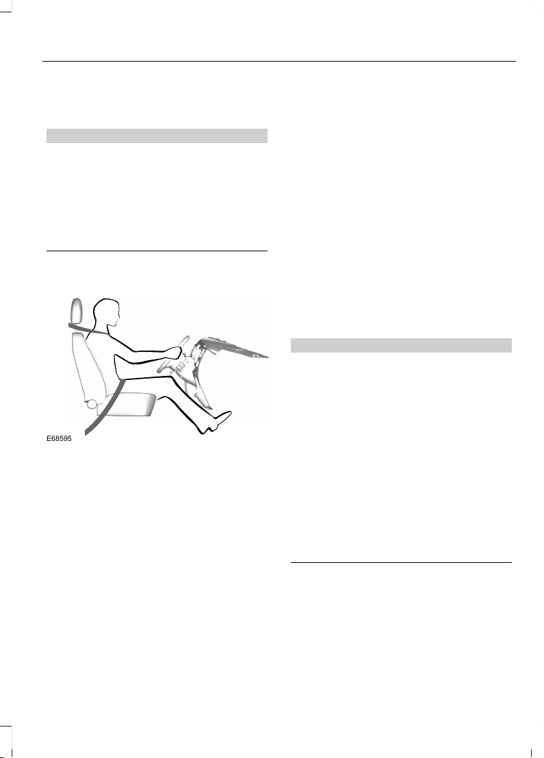
SITTING IN THE CORRECT POSITION
WARNINGS
Do not recline the seatback as this
can cause the occupant to slide
under the safety belt, resulting in
serious injury in the event of a crash.
Do not place objects higher than the
seatback to reduce the risk of serious
injury in the event of a crash or during
heavy braking.
E68595
When you use them properly, the seat,
head restraint, safety belt and airbags will
provide optimum protection in the event
of a crash.
We recommend that you follow these
guidelines:
• Sit in an upright position with the base
of your spine as far back as possible.
• Do not recline the seatback more than
30 degrees.
• Adjust the head restraint so that the
top of it is level with the top of your
head and as far forward as possible.
Make sure that you remain
comfortable.
• Keep sufficient distance between
yourself and the steering wheel. We
recommend a minimum of 10 in
(25 cm) between your breastbone and
the airbag cover.
• Hold the steering wheel with your arms
slightly bent.
• Bend your legs slightly so that you can
press the pedals fully.
• Position the shoulder strap of the
safety belt over the center of your
shoulder and position the lap strap
tightly across your hips.
Make sure that your driving position is
comfortable and that you can maintain full
control of your vehicle.
HEAD RESTRAINTS
WARNINGS
Fully adjust the head restraint before
you sit in or operate your vehicle. This
will help minimize the risk of neck
injury in the event of a crash. Do not adjust
the head restraint when your vehicle is
moving.
The head restraint is a safety device.
Whenever possible it should be
installed and properly adjusted when
the seat is occupied. An improperly
adjusted head restraint may not
adequately protect an occupant during an
impact from the rear.
Install the head restraint properly to
help minimize the risk of neck injury
in the event of a crash.
73
F650750 (TBC), enUSA, First Printing
Seats
Page 77
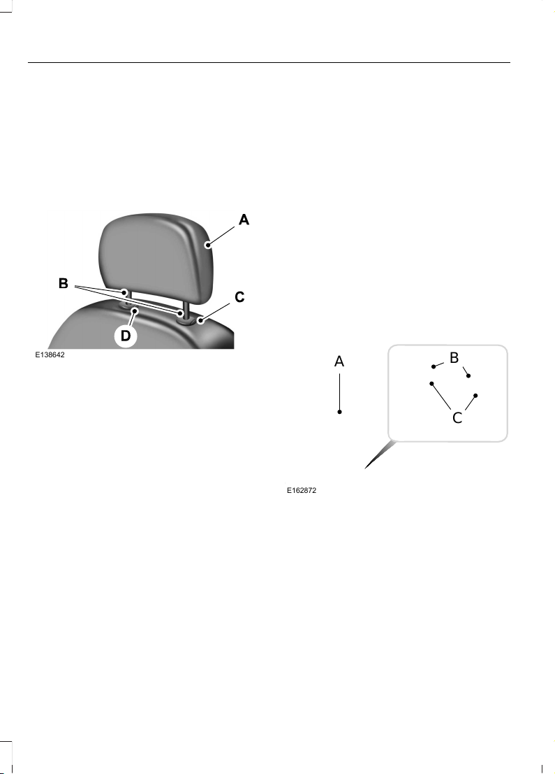
Note: Adjust the seat back to an upright
driving position before adjusting the head
restraint. Adjust the head restraint so that
the top of it is level with the top of your head
and as far forward as possible. Make sure
that you remain comfortable. If you are
extremely tall, adjust the head restraint to
its highest position.
Front Seat Head Restraint
E138642
The head restraints consist of:
An energy absorbing head
restraint.
A
Two steel stems.B
Guide sleeve adjust and release
button.
C
Guide sleeve unlock and remove
button.
D
Adjusting the Head Restraint
Raising the Head Restraint
Pull the head restraint up.
Lowering the Head Restraint
1. Press and hold button C.
2. Push the head restraint down.
Removing the Head Restraint
1. Press and hold buttons C and D.
2. Pull the head restraint up.
Installing the Head Restraint
Align the steel stems into the guide sleeves
and push the head restraint down until it
locks.
Front Row Center, Outboard (Crew
Cab), and Rear Seat Center (Crew Cab)
Head Restraints
Note: The SuperCab has rear outboard
head restraints that are not removable and
are bolted to the back wall.
Your vehicle may be equipped with head
restraints that are non-adjustable. The
non-adjustable head restraints consist of:
E162872
A
C
B
An energy absorbing head
restraint.
A
Two steel stems.B
Guide sleeve unlock and remove
button.
C
Removing the Head Restraint
1. Press and hold buttons C.
2. Pull up the head restraint.
74
F650750 (TBC), enUSA, First Printing
Seats
Page 78
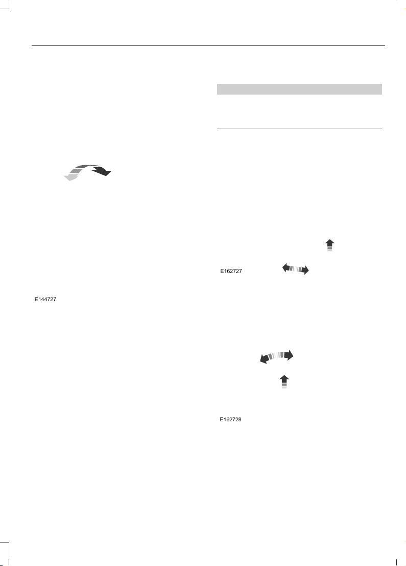
Installing the Head Restraint
Align the steel stems into the guide sleeves
and push the head restraint down until it
locks.
Tilting Head Restraints (If Equipped)
The front head restraints tilt for extra
comfort. To tilt the head restraint, do the
following:
E144727
1. Adjust the seat back to an upright
driving or riding position.
2. Pivot the head restraint forward toward
your head to the desired position.
After the head restraint reaches the
forward-most tilt position, pivot it forward
again to release it to the rearward, un-tilted
position.
Note: Do not attempt to force the head
restraint backward after it is tilted. Instead,
continue tilting it forward until the head
restraint releases to the upright position.
MANUAL SEATS
WARNING
Do not adjust the driver seat or
seatback when your vehicle is
moving.
Moving the Seat Backward and
Forward
E162727
Recline Adjustment
Type 1
E162728
75
F650750 (TBC), enUSA, First Printing
Seats
Page 79
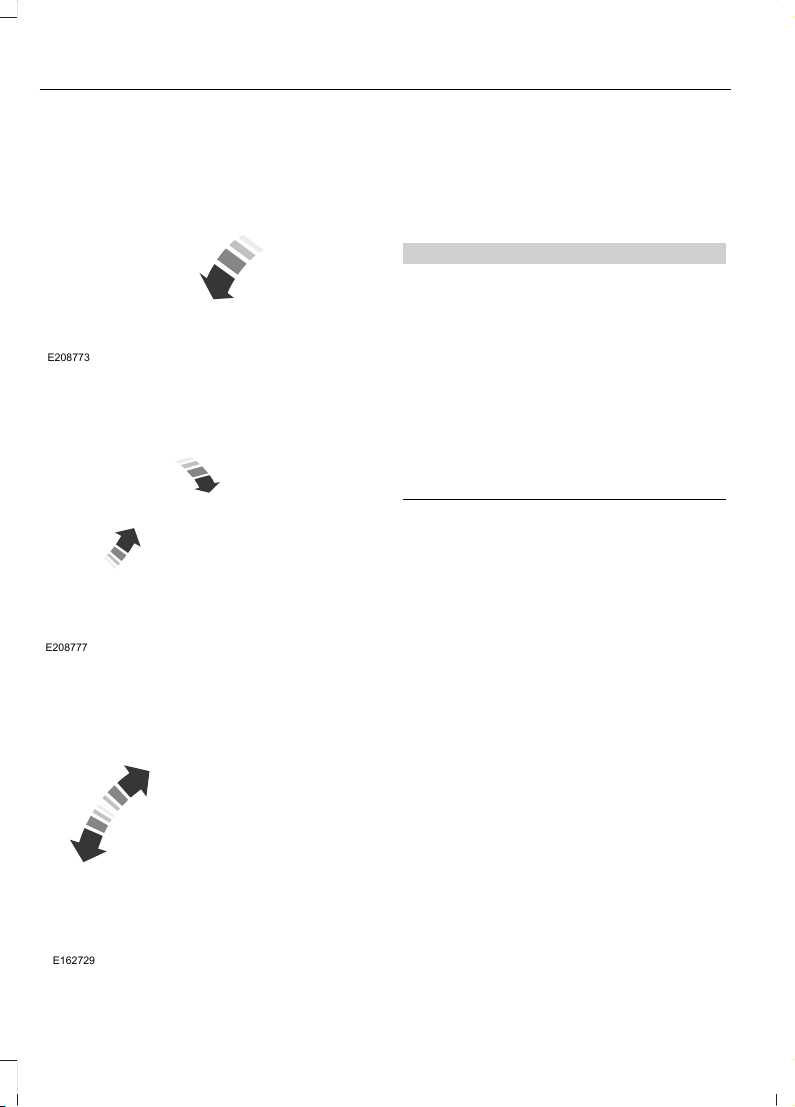
Type 2
E208773
Tilting the Seatback Forward
(Two-Passenger Bench Seat)
E208777
Lift the handle to unlock and release the
seatback forward.
Manual Lumbar (If Equipped)
E162729
The lumbar support control is located on
the outboard side of the seat. Turn the
control to adjust your support.
POWER SEATS (If Equipped)
WARNINGS
Do not adjust the driver seat or
seatback while your vehicle is
moving. Adjusting your seatback
while the vehicle is in motion may cause
loss of control of the vehicle.
To reduce the risk of excess slack in
the belt system, always adjust the
seat height before fastening the seat
belt.
Do not place cargo or any objects
behind the seatback before returning
it to the original position.
76
F650750 (TBC), enUSA, First Printing
Seats
Page 80
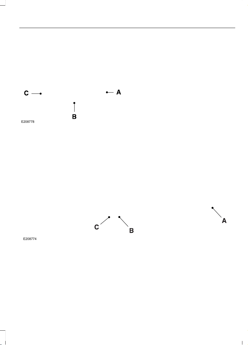
Air-Ride Seat
Type 1
Recline - Rotate the handle to
adjust the angle of the seatback.
A.
Seat height adjuster - Press the
control up to raise the seat. Push
the control down to lower the
seat.
B.
Seat adjuster - Lift the bar up to
move the seat forward or
backward. Release the bar to
lock the seat in position.
C
Type 2
E208774
Recline - Rotate the handle to adjust the angle of the seatback.A.
Lumbar - Press the lever up to inflate the lumbar. Press the lever down to deflate
the lumbar.
B.
Seat height adjuster - Press the lever up to raise the seat height. Press the lever
down to lower the seat height.
C.
77
F650750 (TBC), enUSA, First Printing
Seats
Page 81
REAR SEATS
Folding Up the Rear Seats (SuperCab)
E162737
1. Pull the control to release the seat
cushion.
2. Rotate the seat cushion up until it locks
into the vertical storage position.
Returning the Seat to the Seating
Position
WARNING
Make sure that cargo or any objects
are not trapped underneath the seat
cushion before returning the seat
cushion to its original position, and that the
seat cushion locks into place. Failure to do
so may prevent the seat from operating
properly in the event of a crash, which
could increase the risk of serious injury.
1. Pull the control on the side of the seat
to release the seat cushion from the
storage position.
2. Push the seat cushion down until it
locks into the horizontal position.
Folding the Rear Seat Back (Crew
Cab)
E162738
1. Pull forward on the control to fold
down the seatback.
2. Pull down on the handle and lift up on
the seatback to return it to the original
position.
Folding up the Rear Seat Cushion
1. Pull the control to release the seat
cushion.
2. Rotate the seat cushion up until it locks
into the vertical storage position.
Returning the Seat to the Seating
Position
WARNING
Make sure that cargo or any objects
are not trapped underneath the seat
cushion before returning the seat
cushion to its original position, and that the
seat cushion locks into place. Failure to do
so may prevent the seat from operating
properly in the event of a crash, which
could increase the risk of serious injury.
1. Pull the control on the side of the seat
to release the seat cushion from the
storage position.
2. Push the seat cushion down until it
locks into the horizontal position.
78
F650750 (TBC), enUSA, First Printing
Seats
Page 82
FRONT SEAT ARMREST
E162745
Press the button on the right-hand side of
the seat and pull the seatback down to
release the armrest. You can also gain
access to the cupholders and seatback
storage bin.
E162746
Pull up on the tab to open the storage bin
Lift up on the seatback to return it to the
upright position.
E162747
If your vehicle has an under-seat storage
compartment in the seat cushion, lift the
latch to open the lid of the compartment.
You cannot open the lid when the armrest
is down.
E162748
The under-seat storage compartment has
a programmable lock. Use the ignition key
to program the lock to the compartment.
You can power or charge electronics using
the under-seat storage compartment
auxiliary power point. See Auxiliary
Power Points (page 81).
79
F650750 (TBC), enUSA, First Printing
Seats
Page 83
REAR SEAT ARMREST (If Equipped)
Type 1
E162744
Type 2
E208775
Fold the armrest down to use it.
80
F650750 (TBC), enUSA, First Printing
Seats
Page 84

12 Volt DC Power Point
WARNINGS
Do not plug optional electrical
accessories into the cigar lighter
socket. Incorrect use of the cigar
lighter can cause damage not covered by
the vehicle warranty, and can result in fire
or serious injury.
Do not use a power point for
operating a cigar lighter. Incorrect
use of the power points can cause
damage not covered by the vehicle
warranty, and can result in fire or serious
injury.
Note: When you switch the ignition on, you
can use the socket to power 12 volt
appliances with a maximum current rating
of 15 amps.
If the power supply does not work after you
switch the ignition off, switch the ignition
on.
Note: Do not hang any accessory from the
accessory plug.
Note: Do not use the power point over the
vehicle capacity of 12 volt DC 180 watts or
a fuse may blow.
Note: Always keep the power point caps
closed when not in use.
Do not insert objects other than an
accessory plug into the power point. This
will damage the power point and blow the
fuse.
Run the vehicle for full capacity use of the
power point.
To prevent the battery from running out of
charge:
• Do not use the power point longer than
necessary when the vehicle is not
running.
• Do not leave devices plugged in
overnight or when you park your vehicle
for extended periods.
Locations
Power points may be in the following
locations:
• On the instrument panel (two
locations).
• Inside the front under-seat storage
compartment.
• Inside the rear under-seat storage
compartment.
110 Volt AC Power Points (If Equipped)
WARNING
Do not keep electrical devices
plugged in the power point whenever
the device is not in use. Do not use
any extension cord with the 110 volt AC
power point, since it will defeat the safety
protection design. Doing so may cause the
power point to overload due to powering
multiple devices that can reach beyond
the 150 watt load limit and could result in
fire or serious injury.
Note: The power point will turn off when
the ignition is switched off or the battery
voltage drops below 11 volts.
Use the power point for powering electric
devices that require up to 150 watts. It is
on the instrument panel, center area.
E193395
81
F650750 (TBC), enUSA, First Printing
Auxiliary Power Points
Page 85

Note: Depending on your vehicle, the power
point cover may open to the right or upward.
When the indicator light on the power point
is:
• On: The power point is working, the
ignition is on and a device is plugged
in.
• Off: The power point is off, the ignition
is off or no device is plugged in.
• Flashing: The power point is in fault
mode.
The power outlet temporarily turns off
power when in fault mode if the device
exceeds the 150 watt limit. Unplug your
device and switch the ignition off. Switch
the ignition back on, but do not plug your
device back in. Let the system cool off and
switch the ignition off to reset the fault
mode. Switch the ignition back on and
make sure the indicator light remains on.
Do not use the power point for certain
electric devices, including:
• Cathode-ray, tube-type televisions.
• Motor loads, such as vacuum cleaners,
electric saws and other electric power
tools or compressor-driven
refrigerators.
• Measuring devices, which process
precise data, such as medical
equipment or measuring equipment.
• Other appliances requiring an
extremely stable power supply such as
microcomputer-controlled electric
blankets or touch-sensor lamps.
82
F650750 (TBC), enUSA, First Printing
Auxiliary Power Points
Page 86
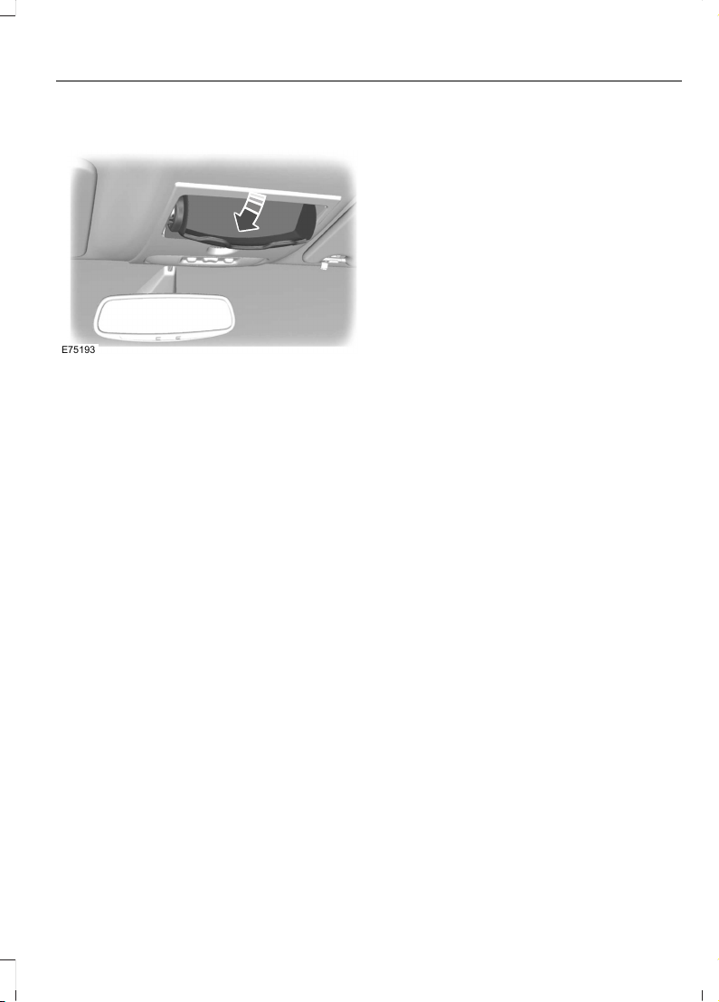
OVERHEAD CONSOLE (If Equipped)
E75193
Press near the rear edge of the door to
open it.
83
F650750 (TBC), enUSA, First Printing
Storage Compartments
Page 87
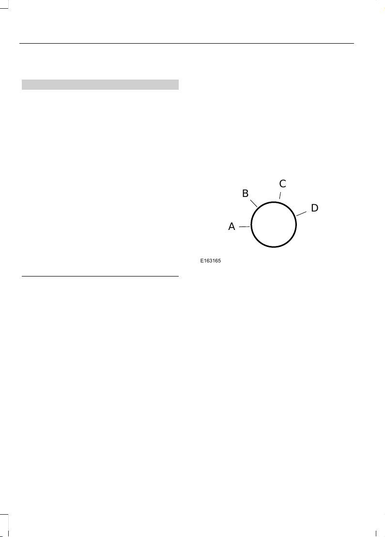
GENERAL INFORMATION
WARNINGS
Extended idling at high engine
speeds can produce very high
temperatures in the engine and
exhaust system, creating the risk of fire or
other damage.
Do not park, idle or drive your vehicle
on dry grass or other dry ground
cover. The emission system heats up
the engine compartment and exhaust
system, creating the risk of fire.
Do not start the engine in a closed
garage or in other enclosed areas.
Exhaust fumes can be toxic. Always
open the garage door before you start the
engine.
If you smell exhaust fumes inside
your vehicle, have your vehicle
checked by your authorized dealer
immediately. Do not drive your vehicle if
you smell exhaust fumes.
If you disconnect the battery, your vehicle
may exhibit some unusual driving
characteristics for approximately 5 miles
(8 kilometers) after you reconnect it. This
is because the engine management system
must realign itself with the engine. You can
disregard any unusual driving
characteristics during this period.
The powertrain control system meets all
Canadian interference-causing equipment
standard requirements regulating the
impulse electrical field or radio noise.
When you start the engine, avoid pressing
the accelerator pedal before and during
operation. Only use the accelerator pedal
when you have difficulty starting the
engine.
If your vehicle is operated in a heavy snow
storm or blowing snow conditions, the
engine air induction may become partially
clogged with snow and ice. If this occurs,
the engine may experience a significant
reduction in power output. At the earliest
opportunity, clear all the snow and ice
away from the air induction inlet.
IGNITION SWITCH
C
D
B
A
E163165
A (off) - The ignition is off.
Note: When you switch the ignition off and
leave your vehicle, do not leave your key in
the ignition. This could cause your vehicle
battery to lose charge.
B (accessory) - Allows the electrical
accessories, such as the radio, to operate
while the engine is not running.
Note: Do not leave the ignition key in this
position for too long. This could cause your
vehicle battery to lose charge.
C (on) - All electrical circuits are
operational and the warning lamps and
indicators illuminate.
D (start) - Cranks the engine.
84
F650750 (TBC), enUSA, First Printing
Starting and Stopping the Engine
Page 88

STARTING A GASOLINE ENGINE
When you start the engine, the idle speed
increases, this helps to warm up the
engine. If the engine idle speed does not
slow down automatically, have your
vehicle checked by an authorized dealer.
Before starting the engine check the
following:
• Make sure all occupants have fastened
their safety belts.
• Make sure the headlamps and
electrical accessories are off.
• Make sure the parking brake is on.
• Make sure the transmission is in park
(P) or neutral (N).
• Turn the ignition key to the on position.
Note: Do not touch the accelerator pedal.
1. Fully press the brake pedal.
2. Turn the key to the start position to
start the engine. Release the key when
the engine starts.
Note: The engine may continue cranking
for up to 15 seconds or until it starts.
Note: If you cannot start the engine on the
first try, wait for a short period and try again.
Failure to Start
If you cannot start the engine after three
attempts, wait 10 seconds and follow this
procedure:
1. Fully press the brake pedal.
2. Fully press the accelerator pedal and
hold it there.
3. Start the engine.
Stopping the Engine When Your
Vehicle is Stationary
1. Shift into park (P) or neutral (N).
2. Turn the key to the off position.
3. Apply the parking brake.
Stopping the Engine When Your
Vehicle is Moving
WARNING
Switching off the engine when the
vehicle is still moving will result in a
loss of brake and steering assistance.
The steering will not lock, but higher effort
will be required. When the ignition is
switched off, some electrical circuits,
including air bags, warning lamps and
indicators may also be off. If the ignition
was turned off accidentally, you can shift
into neutral (N) and re-start the engine.
1. Put the transmission into neutral (N)
and use the brakes to bring your vehicle
to a safe stop.
2. When your vehicle has stopped, shift
into park (P) or neutral (N) and switch
the ignition off.
3. Apply the parking brake.
Guarding Against Exhaust Fumes
WARNING
If you smell exhaust fumes inside
your vehicle, have your vehicle
checked by your authorized dealer
immediately. Do not drive your vehicle if
you smell exhaust fumes. Carbon
monoxide is present in exhaust fumes.
Take precautions to avoid its dangerous
effects.
Important Ventilating Information
If you stop your vehicle and then leave the
engine idling for long periods of time, we
recommend that you do one of the
following:
85
F650750 (TBC), enUSA, First Printing
Starting and Stopping the Engine
Page 89

• Open the windows at least 1 in (3 cm).
• Set your climate control to outside air.
STARTING A DIESEL ENGINE
WARNING
Operation of a diesel engine near
flammable vapors in the air may
cause the engine speed to increase
uncontrollably and over speed. If this
situation occurs, mechanical damage, fire,
explosion, personal injury or death could
result. Turning off the ignition key does not
slow or stop the engine due to
uncontrollable fueling of the engine
through flammable vapors being drawn
into the engine air inlet. Operation of
components, for example starter,
alternator, electric motors and static
electricity could also ignite flammable
vapors. Do not operate your vehicle in the
possible presence of flammable vapors
unless both a complete hazard analysis is
carried out and necessary additional safety
processes and/or equipment, for example
vapor testing, air intake shutoff devices
and ventilation are utilized. You are
responsible for using those processes
and/or equipment to make sure that the
diesel engine and all other components on
your vehicle can be operated safely under
the specific conditions and hazards that
may be encountered.
Read all starting instructions carefully
before you start your vehicle.
Diesel Engine Fast Start Glow Plug
System
The diesel engine glow system consists of:
• Eight glow plugs (one per cylinder)
• Glow Plug Control Module
• Engine Coolant Temperature sensor
• Barometric pressure sensor
• Environmental temperature sensor
The powertrain and glow plug control
modules electronically control the glow
plug system. After you switch the ignition
on the glow plug control module
immediately energizes the glow plugs. The
glow plug control module using the engine
coolant temperature, barometric pressure
sensor and environmental temperature
sensor will determine how long the glow
plugs stay energized. The required time for
the glow plugs to be energized decreases
as the coolant temperature, barometric
pressure and environmental temperature
increase.
Before starting the engine, check the
following:
• Make sure all occupants have fastened
their safety belts.
• Make sure the headlamps and
electrical accessories are off.
• Make sure the parking brake is on.
• Make sure the transmission is in park
(P) or neutral (N).
• Turn the ignition key to the on position.
Note: Do not press the accelerator during
starting.
Cold Weather Starting
WARNINGS
Do not use starting fluid, for example
ether, in the air intake system (see
air filter decal). Such fluid could
cause immediate explosive damage to the
engine and possible personal injury.
Do not add gasoline, gasohol, alcohol
or Kerosene to diesel fuel. This
practice creates a serious fire hazard
and causes engine performance problems.
86
F650750 (TBC), enUSA, First Printing
Starting and Stopping the Engine
Page 90

We recommend using the engine block
heater for starting when the ambient
temperature is at or below-9°F (-23°C)
See Engine Block Heater (page 88).
When operating in cold weather, you can
use Motorcraft® cetane improvers or
non-alcohol-based cetane improvers from
a reputable manufacturer as needed.
Do not crank the engine for more than 10
seconds as starter damage may occur. If
the engine fails to start, turn the key to the
off position and wait 30 seconds before
trying again.
Your vehicle may be equipped with a cold
weather starting strategy that prevents
severe engine damage by assisting in
engine lubrication warm-up. In extremely
cold ambient temperatures, this strategy
activates and prevents the accelerator
pedal use for 30 seconds after starting
your vehicle. A message appears in the
information display as your vehicle warms
up. By not allowing the accelerator pedal
use, the engine oil can properly lubricate
the bearings preventing engine damage
due to lack of proper lubrication. After the
30-second warm-up period, the
accelerator pedal is operational again and
a message appears informing you that your
vehicle is ok to drive.
When starting the engine in extremely cold
temperatures, for example -15°F (-26°C),
we recommend you allow the engine to
idle for several minutes before driving your
vehicle.
Illuminates when you switch the
ignition on as part of the
pre-starting system.
1. Turn the key to the on position without
turning the key to the start position. Do
not start the engine until the wait to
start indicator turns off.
2. When the wait to start indicator turns
off, turn the key to the start position
and release the key as soon as the
engine starts. After starting the engine,
the glow plugs may remain on for a
period. If you do not start the engine
before the glow plug activation time
ends, you need to reset the glow plugs
by turning the key to the off position.
3. After the engine starts, allow it to idle
for about 15 seconds. This is to protect
the engine. Do not increase engine
speed until the oil pressure gauge
indicates normal pressure.
DIESEL PARTICULATE FILTER
Your vehicle is equipped with a diesel
particulate filter. The diesel particulate
filter is an inline filter in the exhaust system
that reduces carbon emissions by trapping
exhaust particles before they reach the
tailpipe. The diesel particulate filter looks
similar to a traditional exhaust catalyst,
except larger, and is part of the exhaust
system under your vehicle. The filter
couples to a diesel oxidation catalyst that
reduces the amount of harmful exhaust
emitted from the tailpipe. As soot gathers
in the system, it begins to restrict the filter.
Periodically, you need to clean the soot
that gathers inside the filter. You can clean
the soot in two different ways, passive
regeneration and active regeneration. See
Emission Control System (page 105).
Both methods occur automatically and
require no actions from the driver. During
either one of these regeneration methods,
you may notice a change in exhaust tone.
At certain times, various messages related
to the diesel particulate filter appear in the
information displays.
87
F650750 (TBC), enUSA, First Printing
Starting and Stopping the Engine
Page 91

SWITCHING OFF THE ENGINE
Allow the engine to idle for three to five
minutes before shutting it down. The larger
the engine, the greater the need is for this
idling period.
Note: Try to limit engine idle to 10 minutes.
Excessive idling reduces fuel economy.
ENGINE IDLE SHUTDOWN (If
Equipped)
WARNING
In the event of engine shutdown,
make sure your vehicle is safely off
the road and the problem is resolved
before returning to the road. Failure to do
so may result in a crash, serious injury or
death.
This feature automatically shuts down the
engine when it has been idling in park (P)
or neutral (N) for an extended period,
depending on the setting.
When the engine idle shutdown process
has started:
• A chime sounds and a message
appears in the information display
showing a timer counting down from
30 seconds.
• You can reset the timer by pressing the
brake pedal, accelerator pedal, or by
shifting into another gear.
• If you do not intervene within 30
seconds, the engine shuts down and a
message appears in the information
display alerting you that the engine has
shut down.
• Shortly after the engine has shut down,
the electrical system simulates a key
off and even though the ignition is still
on, the electrical system simulates a
normal accessory delay period before
shutting down.
• You must switch the ignition off to
reset the system before restarting your
vehicle.
The engine idle shutdown timer does not
start if:
• The engine is operating in battery
charge protect or power take-off mode.
• The exhaust emission control device is
regenerating.
ENGINE BLOCK HEATER (If
Equipped)
WARNINGS
Failure to follow engine block heater
instructions could result in property
damage or serious personal injury.
Do not use your heater with
ungrounded electrical systems or
two-pronged adapters. There is a risk
of electrical shock.
Note: The heater is most effective when
outdoor temperatures are below 0°F
(-18°C).
The heater acts as a starting aid by
warming the engine coolant. This allows
the climate control system to respond
quickly. The equipment includes a heater
element (installed in the engine block) and
a wire harness. You can connect the
system to a grounded 120-volt AC
electrical source.
88
F650750 (TBC), enUSA, First Printing
Starting and Stopping the Engine
Page 92

We recommend that you do the following
for a safe and correct operation:
• Use a 16-gauge outdoor extension cord
that is product certified by
Underwriter’s Laboratory (UL) or
Canadian Standards Association
(CSA). This extension cord must be
suitable for use outdoors, in cold
temperatures, and be clearly marked
Suitable for Use with Outdoor
Appliances. Do not use an indoor
extension cord outdoors. This could
result in an electric shock or become a
fire hazard.
• Use as short an extension cord as
possible.
• Do not use multiple extension cords.
• Make sure that when in operation, the
extension cord plug and heater cord
plug connections are free and clear of
water. This could cause an electric
shock or fire.
• Make sure your vehicle is parked in a
clean area, clear of combustibles.
• Make sure the heater, heater cord and
extension cord are firmly connected.
• Check for heat anywhere in the
electrical hookup once the system has
been operating for approximately 30
minutes.
• Make sure the system is unplugged and
properly stowed before starting and
driving your vehicle. Make sure the
protective cover seals the prongs of the
block heater cord plug when not in use.
• Make sure the heater system is
checked for proper operation before
winter.
Using the Engine Block Heater
Make sure the receptacle terminals are
clean and dry prior to use. Clean them with
a dry cloth if necessary.
The heater uses 0.4 to 1.0 kilowatt-hours
of energy per hour of use. The system does
not have a thermostat. It achieves
maximum temperature after
approximately three hours of operation.
Using the heater longer than three hours
does not improve system performance and
unnecessarily uses electricity.
Rapid Heat Supplemental Heating
System
Note: Additional aftermarket electrical
loads operated during engine warm up may
affect the performance of the rapid heat
supplemental heater.
The optional rapid heat feature is an
electrically powered device that provides
supplemental heat during engine warm up.
During initial warm up, you should use a
mid to low blower speed for maximum
effectiveness. When operating in
automatic mode (when equipped) the
climate control unit determines the
appropriate blower speed for existing
conditions.
89
F650750 (TBC), enUSA, First Printing
Starting and Stopping the Engine
Page 93

SAFETY PRECAUTIONS
WARNINGS
Do not overfill the fuel tank. The
pressure in an overfilled tank may
cause leakage and lead to fuel spray
and fire.
The fuel system may be under
pressure. If you hear a hissing sound
near the fuel filler inlet, do not refuel
until the sound stops. Otherwise, fuel may
spray out, which could cause serious
personal injury.
Fuels can cause serious injury or
death if misused or mishandled.
Gasoline may contain benzene,
which is a cancer-causing agent.
When refueling always shut the
engine off and never allow sparks or
open flames near the fuel tank filler
valve. Never smoke or use a cell phone
while refueling. Fuel vapor is extremely
hazardous under certain conditions. Avoid
inhaling excess fumes.
Flow of fuel through a fuel pump
nozzle can produce static electricity.
This can cause a fire if you are filling
an ungrounded fuel container.
Stop refueling after the fuel pump
nozzle automatically shuts off for the
second time. Failure to follow this
will fill the expansion space in the fuel tank
and could lead to fuel overflowing.
Observe the following guidelines when
handling automotive fuel:
• Extinguish all smoking materials and
any open flames before refueling your
vehicle.
• Automotive fuels can be harmful or
fatal if swallowed. Fuel such as
gasoline is highly toxic and if
swallowed can cause death or
permanent injury. If swallowed, call a
physician immediately, even if no
symptoms are immediately apparent.
The toxic effects of fuel may not be
visible for hours.
• Avoid inhaling fuel vapors. Inhaling too
much fuel vapor of any kind can lead
to eye and respiratory tract irritation.
In severe cases, excessive or prolonged
breathing of fuel vapor can cause
serious illness and permanent injury.
• Avoid getting fuel liquid in your eyes. If
you splash fuel in your eyes, remove
contact lenses (if worn), flush with
water for 15 minutes and seek medical
attention. Failure to seek proper
medical attention could lead to
permanent injury.
• Fuels can also be harmful if absorbed
through the skin. If you splash fuel on
your skin, clothing or both, promptly
remove contaminated clothing and
wash your skin thoroughly with soap
and water. Repeated or prolonged skin
contact with fuel liquid or vapor causes
skin irritation.
• Be particularly careful if you are taking
“Antabuse” or other forms of disulfiram
for the treatment of alcoholism.
Breathing gasoline vapors, or skin
contact could cause an adverse
reaction. In sensitive individuals, serious
90
F650750 (TBC), enUSA, First Printing
Fuel and Refueling
Page 94
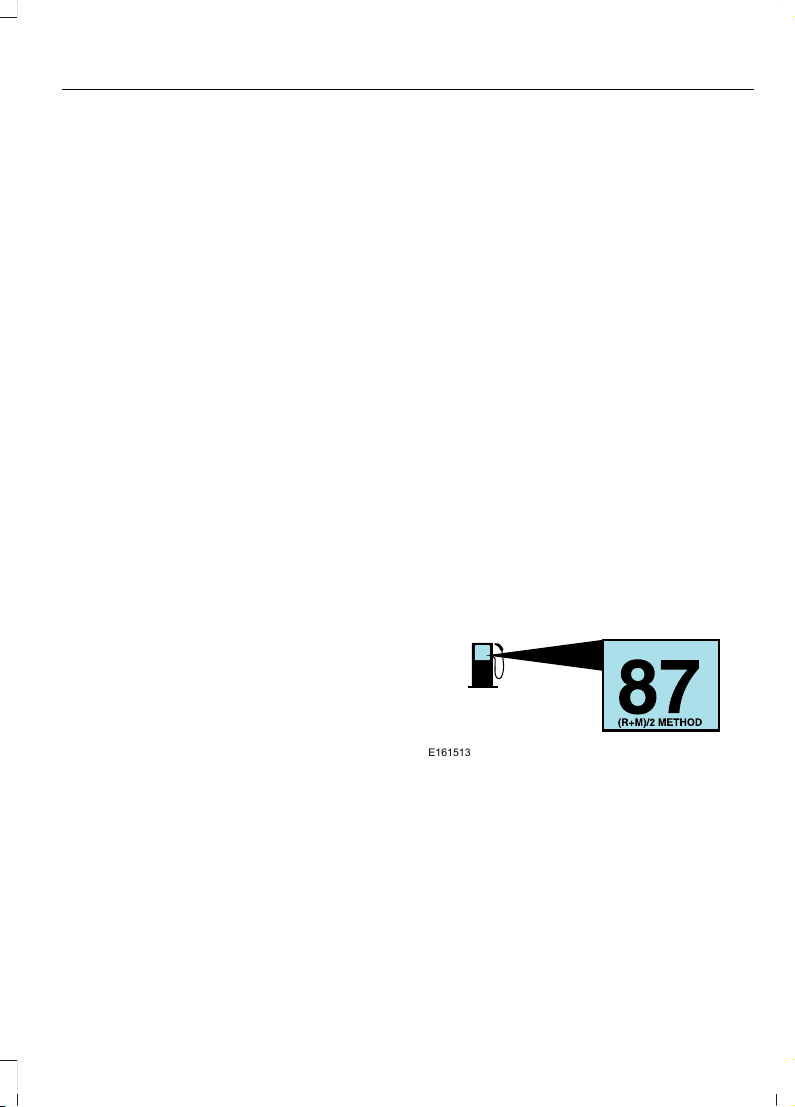
personal injury or sickness may result.
If you splash fuel on your skin, promptly
wash your skin thoroughly with soap
and water. Consult a physician
immediately if you experience an
adverse reaction.
Low Fuel Pressure (If Equipped)
Diesel engine vehicles have a low fuel
pressure detection system.
The following are possible causes for a low
fuel pressure warning message to appear
in the information display:
• Cold start or during cold operation
below 32°F (0°C). If the low fuel
pressure message appears during a
cold start or up to 10 minutes after the
initial cold start, monitor the
information display. If the low fuel
pressure message disappears and does
not re-appear after the engine has fully
warmed up, waxed or gelled fuel is
what most likely caused the message.
Do not use alcohol based additives to
correct fuel gelling. This may result in
damage to the fuel injectors and
systems. Use an anti-gel additive. See
Capacities and Specifications (page
256).
Note: The vehicle Warranty may be void if
you use additives that do not meet or
exceed Ford specifications. If the low fuel
pressure message persistently appears after
re-fueling and then disappears when the
engine has fully warmed up, consider using
different fuel sources.
• Low fuel operation: If the low fuel
pressure message appears when your
vehicle is warm and during low fuel
tank level operation (near empty),
refuel your vehicle. If the message
reappears after fueling, see below. If
the message does not come back, the
low fuel pressure condition was due to
low fuel levels in the fuel tank.
• Normal operation: If the low fuel
pressure message appears during
normal operation when the engine is
fully warm, and fuel level is not low,
you must change the fuel filters
regardless of the maintenance
schedule interval.
• If replacement of the fuel filter does
not remedy the low fuel pressure
message during normal operation as
defined above, take the vehicle to an
authorized dealer.
FUEL QUALITY - GASOLINE
Choosing the Right Fuel
E161513
We recommend regular unleaded gasoline
with a pump (R+M)/2 octane rating of 87.
Some fuel stations offer fuels posted as
regular unleaded gasoline with an octane
rating below 87, particularly in high altitude
areas. We do not recommend fuels with
an octane rating below 87.
Do not use any fuel other than those
recommended because they could lead to
engine damage that may not be covered
by the vehicle Warranty.
91
F650750 (TBC), enUSA, First Printing
Fuel and Refueling
Page 95

Note: Use of any fuel other than those
recommended can impair the emission
control system and cause a loss of vehicle
performance.
Do not use:
• Diesel fuel.
• Fuels containing kerosene or paraffin.
• Fuel containing more than 10% ethanol
or E85 fuel.
• Fuels containing methanol.
• Fuels containing metallic-based
additives, including manganese-based
compounds.
• Fuels containing the octane booster
additive, methylcyclopentadienyl
manganese tricarbonyl (MMT).
• Leaded fuel (using leaded fuel is
prohibited by law).
The use of fuels with metallic compounds
such as methylcyclopentadienyl
manganese tricarbonyl (commonly known
as MMT), which is a manganese-based
fuel additive, will impair engine
performance and affect the emission
control system.
Do not be concerned if the engine
sometimes knocks lightly. However, if it
knocks heavily under most driving
conditions while you are using fuel with the
recommended octane rating, contact an
authorized dealer to prevent any engine
damage.
FUEL QUALITY - DIESEL
Fuel Requirements - Choosing The
Right Fuel: Vehicles Operated
Where Ultra Low Sulfur Diesel Fuel
Is Required (United
States/Canada/Puerto Rico/U.S.
Virgin Islands And Other Locales)
You should use Ultra-Low Sulfur Diesel
fuel (also known as ULSD) designated as
number 1-D or 2-D with a maximum of
15-ppm sulfur in your diesel vehicle. You
may operate your vehicle on diesel fuels
containing up to 20% biodiesel, also
known as B20. These fuels should meet
the ASTM D975 diesel or the ASTM D7467
B6-B20 biodiesel industry specifications.
Outside of North America, use fuels
meeting EN590 or equivalent local market
standard.
Note: The vehicle Warranty does not cover
damage caused by using an improper type
of fuel or fuel additive.
Note: Do not blend used engine oil with
diesel fuel under any circumstances.
Blending used oil with the fuel will
significantly increase your vehicle’ s exhaust
emissions and reduce engine life due to
increased internal wear.
Using low sulfur diesel fuel
(16-500 ppm) or high sulfur
diesel fuel (greater than 500
ppm) in your diesel engine will cause
certain emission components to
malfunction which may also cause the
service engine soon light to illuminate
indicating an emissions-related concern.
Diesel fuel is adjusted seasonally for cold
temperature. For best results at
temperatures below 19°F (-7°C), it is
recommended to use a diesel fuel which
has been seasonally adjusted for the
ambient conditions.
92
F650750 (TBC), enUSA, First Printing
Fuel and Refueling
Page 96

Fuel Requirements - Choosing The
Right Fuel: Vehicles Operated
Where Ultra Low Sulfur Diesel Fuel
Is Not Required
For the engine to operate reliably on
low-sulfur or high-sulfur diesel fuel, the
engine must be a factory built high-sulfur
engine (available as a dealer order option
for select markets) or an ultra low sulfur
diesel fuel configured engine that has been
retrofitted for high-sulfur diesel fuel using
Ford Motor Company dealer service parts.
Failure to use retrofit components other
than those available through your
authorized dealer will result in coolant
system damage, engine overheating,
selective catalyst reduction system or
diesel particulate filter damage and
possible base engine damage.
Use only a diesel engine configured for use
with high sulfur diesel fuel in markets with
diesel fuel that has sulfur content greater
than 15 ppm. Using low sulfur diesel fuel
(16–500 ppm) or high sulfur diesel fuel
(greater than 500 ppm) in a diesel engine
designed to use only Ultra Low Sulfur
Diesel fuel may result in damage to engine
emission control devices and the
aftertreatment system, potentially
rendering the vehicle inoperable.
Vehicles with engines configured for use
with high sulfur diesel fuel are only
available for sale in countries where ultra
low sulfur diesel fuel is generally not
available or mandated by the government.
Vehicles originally sold in a ultra low sulfur
diesel fuel market that are subsequently
exported to non- ultra low sulfur diesel fuel
markets will need to be retrofitted (at the
customer’s expense using Ford authorized
dealer service parts) in order to be reliably
operated on non- ultra low sulfur diesel
fuel.
Biodiesel
WARNINGS
Do not use home heating oil,
agricultural fuel, raw fats and oils,
waste cooking greases, biodiesel
fuels greater than 20% or any diesel fuel
not intended for highway use. Damage to
the fuel injection system, engine and
exhaust catalyst can occur if an improper
fuel is used. Do not add gasoline, gasohol
or alcohol to diesel fuel. This practice
creates a serious fire hazard and engine
performance problems.
Do not mix diesel fuel with gasoline,
gasohol or alcohol. This could cause
an explosion resulting in personal
injury.
Do not add gasoline, gasohol or
alcohol to diesel fuel. This practice
creates a serious fire hazard resulting
in personal injury and engine performance
problems.
Do not use home heating oil or any
diesel fuel not intended for highway
use. Damage to the fuel injection
system, engine, exhaust catalyst and diesel
particulate filter can occur if an improper
fuel is used. Red dye is used to identify
fuels intended for agricultural and
non-highway use.
You may operate your vehicle on diesel
fuels containing up to 20% biodiesel, also
known as B20.
Biodiesel fuel is a chemically converted
product from renewable fuel sources, such
as vegetable oils, animal fats and waste
cooking greases.
93
F650750 (TBC), enUSA, First Printing
Fuel and Refueling
Page 97

To help achieve acceptable engine
performance and durability when using
biodiesel in your vehicle:
• Confirm the biodiesel content of the
fuel to be B20 (20% biodiesel) or less
• Only use biodiesel fuel of good quality
that complies with industry standards
• Follow the recommended service
maintenance intervals. See
Scheduled Maintenance (page 314).
• Do not store biodiesel fuel in the fuel
tank for more than 1 month
• Consider changing brands or reducing
biodiesel content if you have cold
temperature fuel gelling issues or a
frequent LOW FUEL PRESSURE
message appearing
• Do NOT use raw oils, fats or waste
cooking greases
Use of biodiesel in concentrations greater
than 20% may cause damage to your
vehicle, including engine and/or exhaust
after-treatment hardware (exhaust
catalyst and particulate filter) failures.
Concentrations greater than 20% can also
cause fuel filter restrictions that may result
in a lack of power or damage to fuel
system components, including fuel pump
and fuel injector failures.
SAE 5W-40 or SAE 15W-40 oil is
recommended for fuels with greater than
5% biodiesel (B5). Refer to the Special
operating conditions section under the
Schedule Maintenance chapter for more
information about oil change intervals and
other maintenance when operating on
biodiesel.
Look for a label on the fuel pump to
confirm the amount of biodiesel contained
in a diesel fuel. Biodiesel content is often
indicated with the letter B followed by the
percent of biodiesel in the fuel. For
example, B20 indicates a fuel containing
20% biodiesel. Ask the service station
attendant to confirm the biodiesel content
of a diesel fuel if you do not see a label on
the fuel pump.
Biodiesel fuels degrade more easily than
diesel fuels not containing biodiesel and
should not be stored in the fuel tank for
more than 1 month. If you plan to park or
store your vehicle for more than 1 month,
then you should empty your vehicle fuel
tank of biodiesel fuel. You should fill the
tank with a pure petroleum-based diesel
fuel and run your vehicle for a minimum of
30 minutes.
Note: Degraded or oxidized biodiesel can
damage fuel system seals and plastics and
corrode steel parts.
During cold weather, if you have problems
operating on biodiesel, you may need to
use a diesel fuel with lower biodiesel
content, try another brand, or discontinue
the use of biodiesel.
Diesel Fuel Additives
It should not be necessary to add any
aftermarket additives to your fuel if you
use a high quality diesel fuel that conforms
to ASTM industry specifications.
Aftermarket additives can damage the fuel
injector system or engine.
Use Motorcraft® cetane booster or an
equivalent cetane booster additive if you
suspect fuel has low cetane. Use
Motorcraft® anti-gel & performance
improver or an equivalent additive if there
is fuel gelling.
94
F650750 (TBC), enUSA, First Printing
Fuel and Refueling
Page 98

Do not use alcohol-based additives to
improve cetane quality, to prevent fuel
gelling or any other use. The use of alcohol
additives may result in damage to the fuel
injectors and system. See Capacities and
Specifications (page 261).
The Vehicle Warranty may not cover
repairs needed to correct the effects of
using an aftermarket product that does
not meet Ford specifications in your fuel.
RUNNING OUT OF FUEL - 6.8L
Avoid running out of fuel because this
situation may have an adverse effect on
powertrain components.
If you run out of fuel:
• You may need to switch the ignition
from off to on several times after
refueling to allow the fuel system to
pump the fuel from the tank to the
engine. When restarting, cranking time
takes a few seconds longer than
normal. With keyless ignition, just start
the engine. Crank time will be longer
than usual.
• Normally, adding 1 gal (3.8 L) of fuel is
enough to restart the engine. If the
vehicle is out of fuel and on a steep
grade, more than 1 gal (3.8 L) may be
required.
• The service engine soon indicator may
come on. See Warning Lamps and
Indicators (page 58).
RUNNING OUT OF FUEL - 6.7L
DIESEL
Avoid running out of fuel as this allows air
to enter the fuel system, which makes
restarting your vehicle difficult.
If your vehicle runs out of fuel:
• If your vehicle is equipped with dual
fuel tanks, adding 4 gal (15 L) to 5 gal
(19 L) of fuel is enough to restart the
engine. If your vehicle is out of fuel and
on a steep grade, more than 4 gal
(15 L) to 5 gal (19 L) may be required.
• The fuel system must be primed before
attempting to restart the engine.
• Use caution not to overheat and
damage the starter by cranking the
engine for an excessive period. You
may need to crank the engine for a
longer time than normal. If the engine
fails to start in 30 seconds, turn the
ignition to the off position and wait for
two minutes before cranking the engine
again.
• Any remaining trapped air self-purges
from the fuel system once the engine
starts running.
• The engine may run rough and produce
white smoke while air is in the fuel
system. This is normal and should stop
after a short period.
Purging Air from the Fuel System
Turn the ignition key to on for 30 seconds,
then turn it to off. Do this six times in a row
to purge any trapped air from the fuel
system.
SELECTIVE CATALYTIC REDUCTION SYSTEM
Your vehicle has a selective catalytic
reduction system to help reduce emission
levels of oxides of nitrogen from the
exhaust system. The system automatically
injects diesel exhaust fluid into the exhaust
system to enable correct selective catalytic
reduction system function.
95
F650750 (TBC), enUSA, First Printing
Fuel and Refueling
Page 99
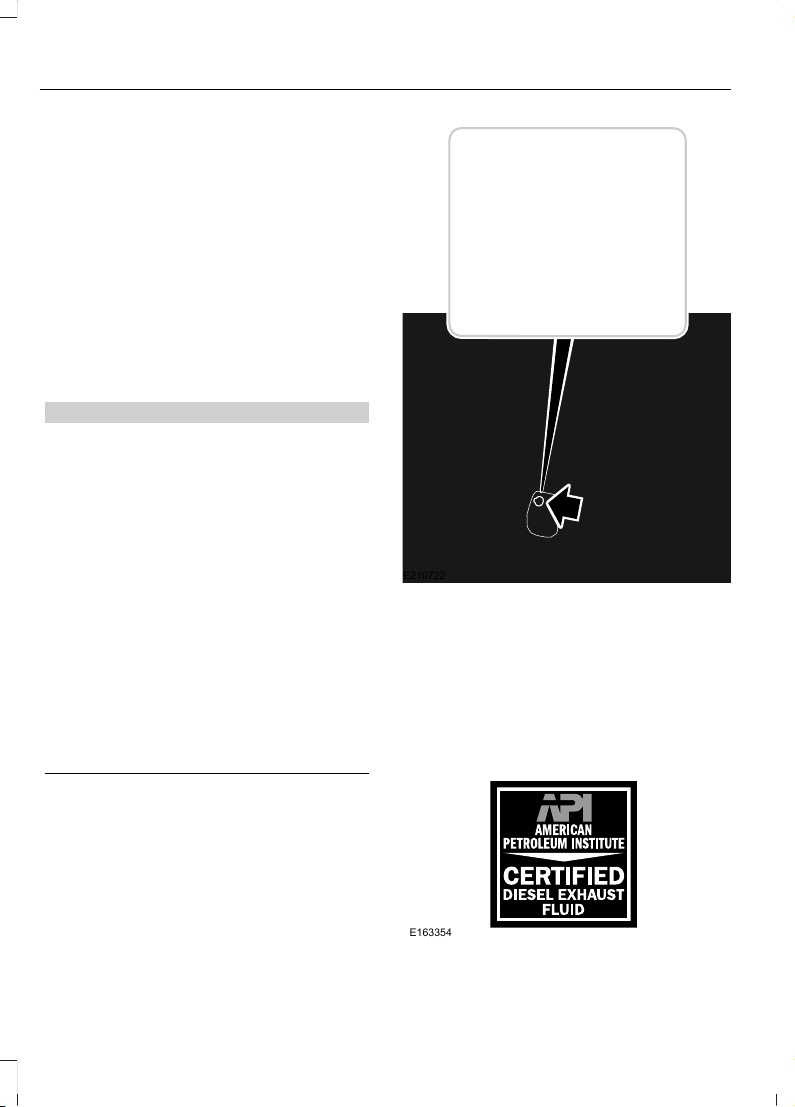
Importance of Maintaining the
Diesel Exhaust Fluid Level
In order for the selective catalytic reduction
system to operate correctly the diesel
exhaust fluid level must be maintained.
A message appears in the information
display when the diesel exhaust fluid level
is low and needs to be refilled. When you
see a warning message, refill the tank as
soon as possible. See Information
Messages (page 64).
Filling the Diesel Exhaust Fluid
Tank
WARNINGS
Make sure that diesel exhaust fluid
does not come into contact with
eyes, skin or clothing. Should any
diesel exhaust fluid contact your eyes,
flush them with plenty of water and
contact a physician. Clean affected skin
with soap and water. If any diesel exhaust
fluid is swallowed, drink plenty of water
and contact a physician immediately.
Refill diesel exhaust fluid in a
well-ventilated area. When opening
the cap on the diesel exhaust fluid
tank or bottle containing diesel exhaust
fluid, ammonia vapors may escape. The
vapors can be irritating to skin, eyes and
mucous membranes. Inhaling ammonia
vapors can cause burning to the eyes,
throat and nose and cause coughing and
watery eyes.
E210722
The diesel exhaust fluid tank has a blue
filler cap and the tank is behind the
left-hand front wheel. Fill the tank using a
fluid pump at a diesel exhaust fluid filling
station or a diesel exhaust fluid container.
We recommend Motorcraft® diesel
exhaust fluid, the containers are spill proof
and stop the flow of fluid when the tank is
full. See Capacities and Specifications
(page 256).
)
E163354
96
F650750 (TBC), enUSA, First Printing
Fuel and Refueling
Page 100

You must only use diesel exhaust fluid that
is certified by the American Petroleum
Institute (API). The vehicle Warranty does
not cover repairs resulting from the use of
non-certified diesel exhaust fluid products.
Note: Do not put diesel exhaust fluid in the
fuel tank. This can cause engine damage
not covered by the vehicle Warranty.
You can purchase diesel exhaust fluid at
an authorized dealer, most highway truck
stops or you can contact roadside
assistance for help in finding a retailer that
sells diesel exhaust fluid. In addition, there
is a government website to help you find
the nearest location to purchase diesel
exhaust fluid:
http://www.discoverdef.com.
Filling the Diesel Exhaust Fluid Tank
Using a Fuel Station Pump
Filling the diesel exhaust fluid tank using
a nozzle is similar to a normal fuel fill. The
nozzle shuts off automatically when the
tank is full.
Filling the Diesel Exhaust Fluid Tank
Using a Container
The following procedure applies to
Motorcraft diesel exhaust fluid or similar
fluid containers. Always follow the
manufacturer's instructions.
1. Remove the diesel exhaust fluid
container cap. Place the spout on to
the container and tighten it until you
feel a strong resistance.
2. Remove the diesel exhaust fluid tank
filler cap.
3. Insert the spout in to the filler neck until
the seal on the spout seats on to the
filler neck. Pour the fluid in to the tank.
When the tank is full the fluid stops
flowing automatically.
4. Return the container to the vertical
position slightly below the diesel
exhaust fluid filler neck. Allow any fluid
remaining in the spout to drain back in
to the container.
5. Remove the spout from the diesel
exhaust fluid filler neck. Replace the
diesel exhaust fluid tank cap.
6. Remove the spout from the diesel
exhaust fluid container and replace the
cap.
7. Wipe away any diesel exhaust fluid
that has spilled on painted surfaces
with water and a damp cloth.
Note: If there is diesel exhaust fluid left in
the container retain it for later use. The
spout is re-useable. Wash the spout with
clean water prior to storage. Do not use the
diesel exhaust fluid spout with any other
fluid.
Filling the Diesel Exhaust Fluid Tank in
Cold Climates
Diesel exhaust fluid freezes below 12°F
(-11°C); however, your vehicle has an
automatic heating system which allows
the diesel exhaust fluid system to operate
below 12°F (-11°C). When your vehicle is
not in operation for an extended period
with temperatures at or below 12°F (-11°C),
the diesel exhaust fluid tank could freeze.
Diesel Exhaust Fluid Warning
Messages and Vehicle Operations
WARNINGS
Diesel exhaust fluid must be refilled
when low or replaced when
contaminated or your vehicle speed
becomes limited to 50 mph (80 km/h). In
these conditions, drive with caution and
refill diesel exhaust fluid immediately. If
the diesel exhaust fluid becomes empty
or contaminated and fluid is not replaced,
97
F650750 (TBC), enUSA, First Printing
Fuel and Refueling
 Loading...