

Page 1

Table of Contents
Introduction 4
Instrument Cluster 12
Warning and control lights 12
Gauges 16
Entertainment Systems 19
AM/FM stereo cassette 19
AM/FM stereo with CD 25
AM/FM stereo cassette with CD 28
Rear seat controls 32
Climate Controls 35
Manual heating and air conditioning 35
Electronic automatic temperature control 38
Rear window defroster 40
Lights 41
Headlamps 41
Turn signal control 43
Bulb replacement 45
Driver Controls 51
Windshield wiper/washer control 51
Steering wheel adjustment 52
Power windows 57
Mirrors 58
Speed control 60
1
Page 2

Table of Contents
Locks and Security 74
Keys 74
Locks 74
Anti-theft system 76
Seating and Safety Restraints 85
Seating 85
Safety restraints 93
Air bags 106
Child restraints 114
Driving 130
Starting 130
Brakes 135
Transmission operation 137
Trailer towing 158
Roadside Emergencies 168
Getting roadside assistance 168
Hazard flasher switch 169
Fuel pump shut-off switch 169
Fuses and relays 170
Changing tires 178
Jump starting 185
Wrecker towing 190
2
Page 3

Table of Contents
Customer Assistance 191
Reporting safety defects (U.S. only) 199
Cleaning 200
Maintenance and Specifications 208
Engine compartment 210
Engine oil 213
Battery 217
Fuel information 225
Air filter(s) 242
Part numbers 247
Refill capacities 248
Lubricant specifications 251
Accessories 261
Index 265
All rights reserved. Reproduction by any means, electronic or mechanical
including photocopying, recording or by any information storage and retrieval
system or translation in whole or part is not permitted without written
authorization from Ford Motor Company. Ford may change the contents without
notice and without incurring obligation.
Copyright © 2002 Ford Motor Company
3
Page 4

Introduction
CALIFORNIA Proposition 65 Warning
WARNING: Engine exhaust, some of its constituents, and
certain vehicle components contain or emit chemicals known to
the State of California to cause cancer and birth defects or other
reproductive harm. In addition, certain fluids contained in vehicles and
certain products of component wear contain or emit chemicals known
to the State of California to cause cancer and birth defects or other
reproductive harm.
CONGRATULATIONS
Congratulations on acquiring your new Ford. Please take the time to get
well acquainted with your vehicle by reading this handbook. The more
you know and understand about your vehicle the greater the safety and
pleasure you will derive from driving it.
For more information on Ford Motor Company and its products visit the
following website:
• In the United States: www.ford.com
• In Canada: www.ford.ca
• In Australia: www.ford.com.au
• In Mexico: www.ford.com.mx
Additional owner information is given in separate publications.
This Owner’s Guide describes every option and model variant available
and therefore some of the items covered may not apply to your
particular vehicle. Furthermore, due to printing cycles it may describe
options before they are generally available.
Remember to pass on the Owner’s Guide when reselling the vehicle. It is
an integral part of the vehicle.
Fuel pump shut-off switch In the event of an accident the
safety switch will automatically cut off the fuel supply to the
engine. The switch can also be activated through sudden vibration (e.g.
collision when parking). To reset the switch, refer to the Fuel pump
shut-off switch in the Roadside emergencies chapter.
4
Page 5
Introduction
SAFETY AND ENVIRONMENT PROTECTION
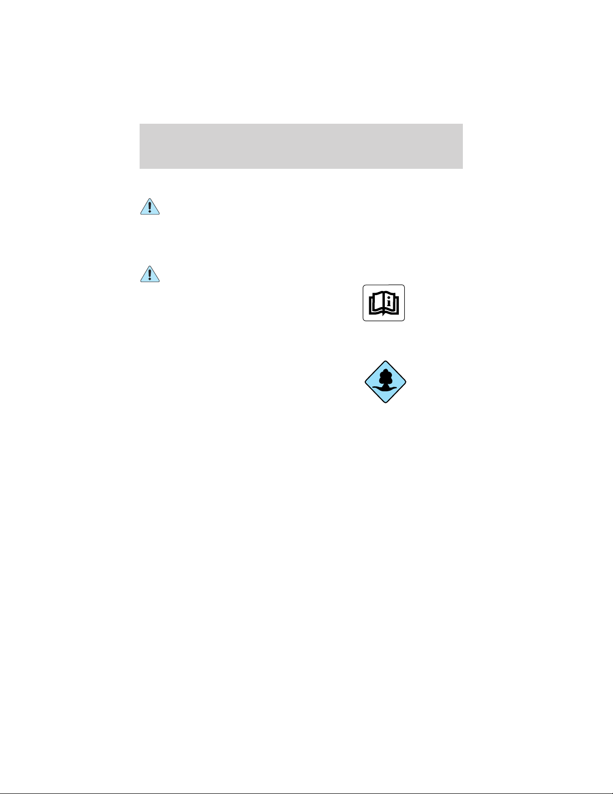
Warning symbols in this guide
How can you reduce the risk of personal injury and prevent possible
damage to others, your vehicle and its equipment? In this guide, answers
to such questions are contained in comments highlighted by the warning
triangle symbol. These comments should be read and observed.
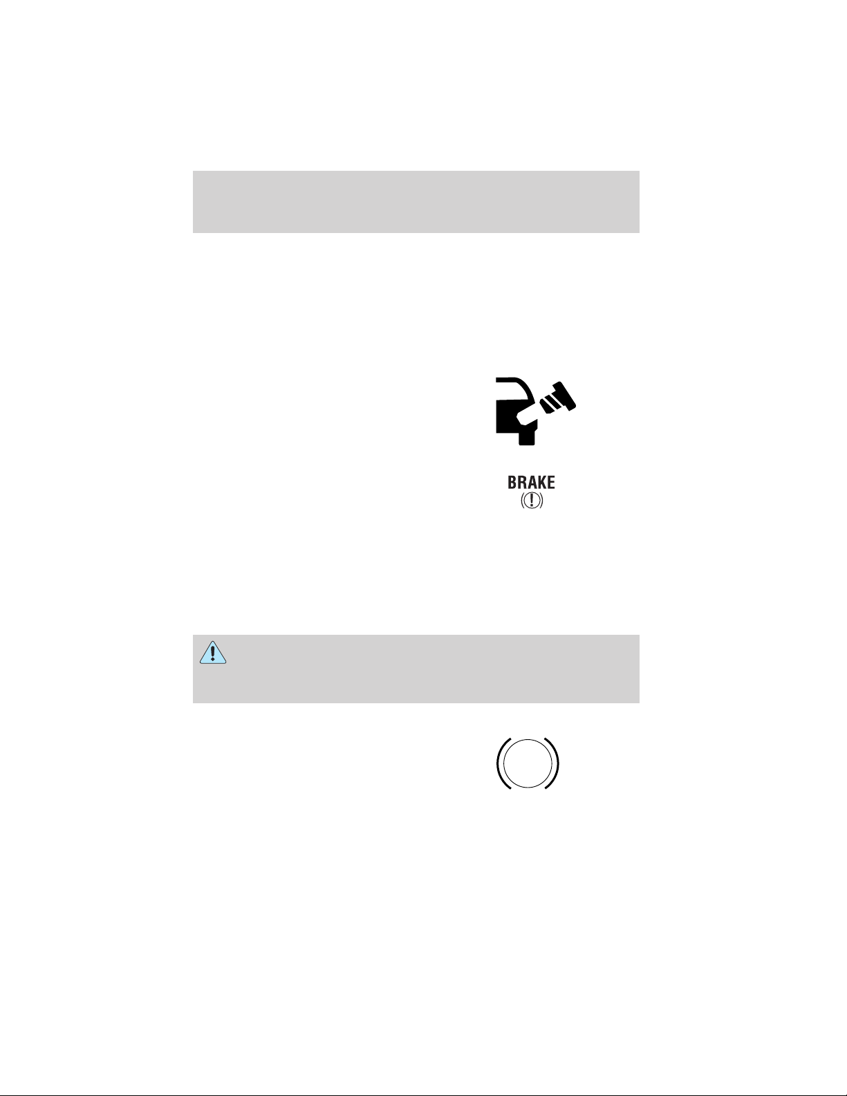
Warning symbols on your vehicle
When you see this symbol, it is
imperative that you consult the
relevant section of this guide before
touching or attempting adjustment
of any kind.
Protecting the environment
We must all play our part in
protecting the environment. Correct
vehicle usage and the authorized
disposal of waste cleaning and
lubrication materials are significant
steps towards this aim. Information in this respect is highlighted in this
guide with the tree symbol.
BREAKING-IN YOUR VEHICLE
Your vehicle does not need an extensive break-in. Try not to drive
continuously at the same speed for the first 1,600 km (1,000 miles) of
new vehicle operation. Vary your speed to allow parts to adjust
themselves to other parts.
Drive your new vehicle at least 800 km (500 miles) before towing a
trailer.
Do not add friction modifier compounds or special break-in oils during
the first few thousand kilometers (miles) of operation, since these
additives may prevent piston ring seating. See Engine oil in the
Maintenance and care chapter for more information on oil usage.
5
Page 6

Introduction
SPECIAL NOTICES
Emission warranty
The New Vehicle Limited Warranty includes Bumper-to-Bumper
Coverage, Safety Restraint Coverage, Corrosion Coverage, and 7.3L
Power Stroke Diesel Engine Coverage. In addition, your vehicle is eligible
for Emissions Defect and Emissions Performance Warranties. For a
detailed description of what is covered and what is not covered, refer to
the Warranty Guide that is provided to you along with your Owner’s
Guide.
Data Recording
Computers in your vehicle are capable of recording detailed data
potentially including but not limited to information such as:
• the use of restraint systems including seat belts by the driver and
passengers,
• information about the performance of various systems and modules in
the vehicle, and
• information related to engine, throttle, steering, brake or other system
status.
Any of this information could potentially including information regarding
how the driver operates the vehicle potentially including but not limited
to information regarding vehicle speed, brake or accelerator application
or steering input. This information may be stored during regular
operation or in a crash or near crash event.
This stored information may be read out and used by:
• Ford Motor Company.
• service and repair facilities.
• law enforcement or government agencies.
• others who may assert a right or obtain your consent to know such
information.
6
Page 7

Introduction
Special instructions
For your added safety, your vehicle is fitted with sophisticated electronic
controls.
Please read the section Air bag in the Seating and safety
restraints chapter. Failure to follow the specific warnings and
instructions could result in personal injury.
Front seat mounted rear facing child or infant seats should
NEVER be used in front of a passenger side air bag unless the
air bag can be and is turned OFF.
Snowplowing
Ford recommends the following specifications for low speed, personal
use snow removal:
• F-150 4x4 (except F-150 Supercrew, Lightning and Harley-Davidson
models)
• 5.4L engine
• Heavy-duty service package
• Super engine cooling
• Heavy-duty front suspension package
• Automatic transmission with auxiliary automatic transmission fluid
cooling
• All-terrain tires
• Limited slip and optional axle ratio.
Do not install a snowplow and plow with your vehicle until it has been
driven at least 800 km (500 miles).
7
Page 8

Introduction
F150 SuperCrew, F150 5.4L Supercharged “Lightning” and
Harley-Davidson F-150 Owners: Snowplowing
Your vehicle is not recommended for snowplowing. Ford makes no
representation as to the suitability of your vehicle for snowplowing, in
particular regarding the potential for exceeding vehicle weight limits,
airbag (SRS) deployment sensitivity, vehicle crash integrity, or
powertrain durability. The Snowplow Package Option is not available.
Using your vehicle as an ambulance
Do not use this vehicle as an ambulance.
Your vehicle is not equipped with the Ford Ambulance Preparation
Package.
Notice to owners of pickup trucks and utility type vehicles
Utility vehicles have a significantly higher rollover rate than
other types of vehicles.
Before you drive your vehicle, please read this Owner’s Guide carefully.
Your vehicle is not a passenger car. As with other vehicles of this type,
failure to operate this vehicle correctly may result in loss of vehicle
control, vehicle rollover, personal injury or death.
Be sure to read Driving off road in the Driving chapter.
Notice to owners of natural gas fueled vehicles
Before you drive your vehicle, be sure to read the Dedicated Natural
Gas Vehicle supplement. This book contains important operation and
maintenance information.
8
Page 9

Introduction
Notice to owners of F150 5.4L Supercharged “Lightning” vehicles
Before you drive your vehicle, be sure to read the “SVT Lightning Truck
Owner’s Guide Supplement.” This book contains important operation and
maintenance information.
Notice to owners of the Harley-Davidson F-150
Note: Your vehicle is not designed to be operated off-road.
The undercab chrome bars are for decorative purposes only. Do not step
on these bars to enter or exit the vehicle.
Harley-Davidson F-150 vehicles are equipped with high performance
tires. When first driving the vehicle after is has been parked, you may
experience a temporary ride disturbance. This is a characteristic of the
tires used on the Harley-Davidson vehicles and should be no reason for
concern. The condition should correct itself within 10–15 miles of
driving.
MIDDLE EAST/NORTH AFRICA VEHICLE SPECIFIC INFORMATION
For your particular global region, your vehicle may be equipped with
features and options that are different from the ones that are described
in this Owner Guide; therefore, a supplement has been supplied that
complements this book. By referring to the pages in the provided
supplement, you can properly identify those features, recommendations
and specifications that are unique to your vehicle. Refer to this Owner
Guide for all other required information and warnings.
9
Page 10
Introduction
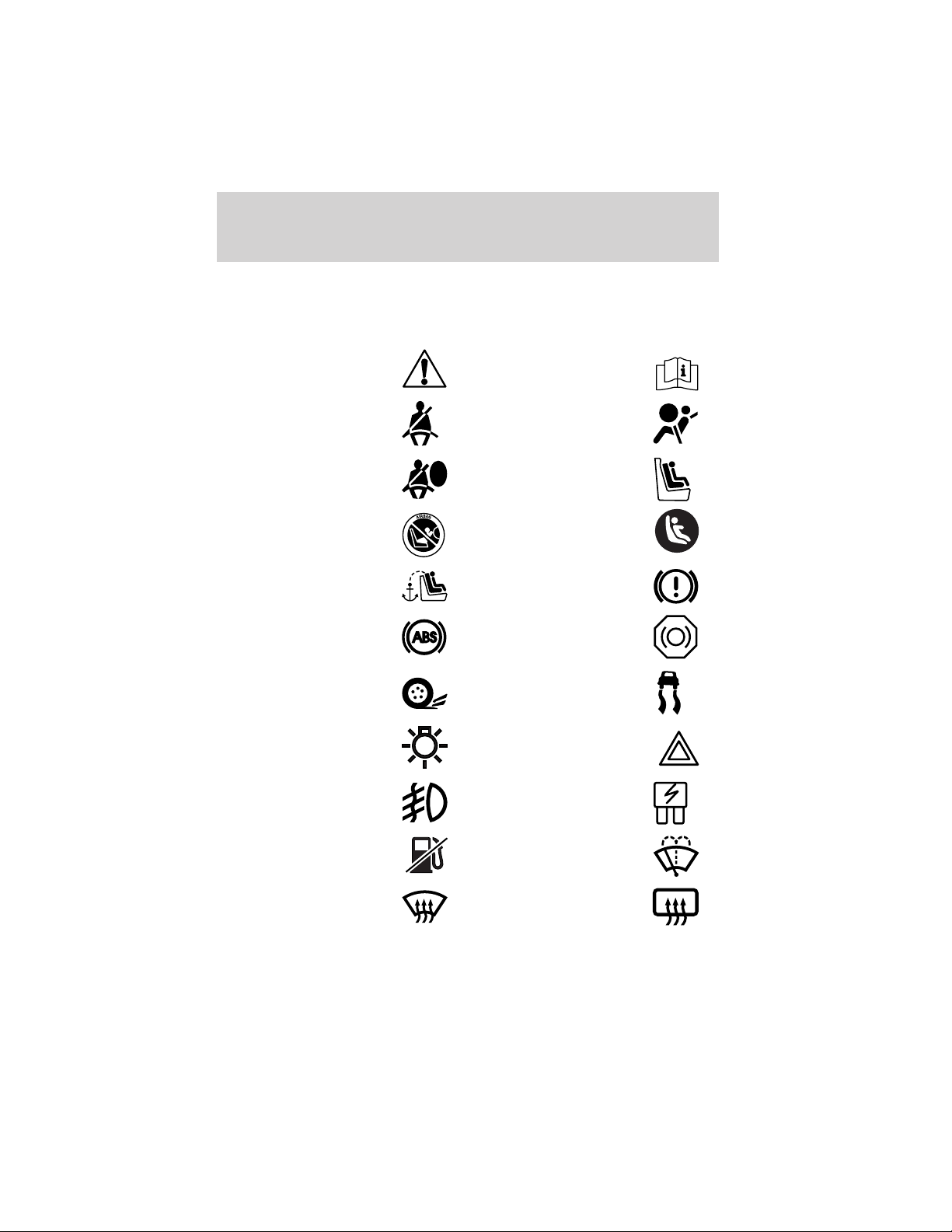
These are some of the symbols you may see on your vehicle.
Vehicle Symbol Glossary
Safety Alert
Fasten Safety Belt Air Bag-Front
Air Bag-Side Child Seat
Child Seat Installation
Warning
Child Seat Tether
Anchor
Anti-Lock Brake System
Traction Control AdvanceTrac
Master Lighting Switch Hazard Warning Flasher
Fog Lamps-Front Fuse Compartment
See Owner’s Guide
Child Seat Lower
Anchor
Brake System
Brake Fluid Non-Petroleum Based
Fuel Pump Reset Windshield Wash/Wipe
Windshield
Defrost/Demist
10
Rear Window
Defrost/Demist
Page 11
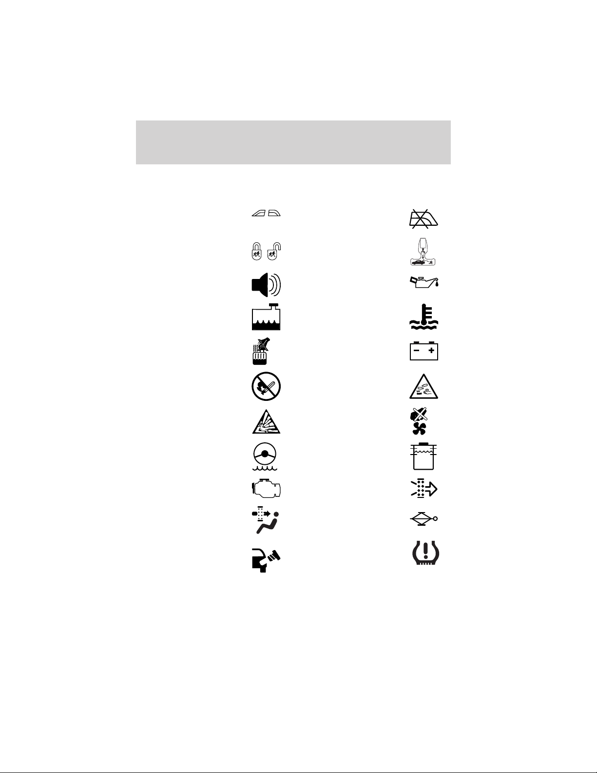
Vehicle Symbol Glossary
Introduction
Power Windows
Front/Rear
Child Safety Door
Lock/Unlock
Power Window Lockout
Interior Luggage
Compartment Release
Symbol
Panic Alarm Engine Oil
Engine Coolant
Engine Coolant
Temperature
Do Not Open When Hot Battery
Avoid Smoking, Flames,
or Sparks
Battery Acid
Explosive Gas Fan Warning
Power Steering Fluid
Maintain Correct Fluid
Level
Emission System Engine Air Filter
MAX
MIN
Passenger Compartment
Air Filter
Jack
Check fuel cap Low tire warning
11
Page 12
Instrument Cluster
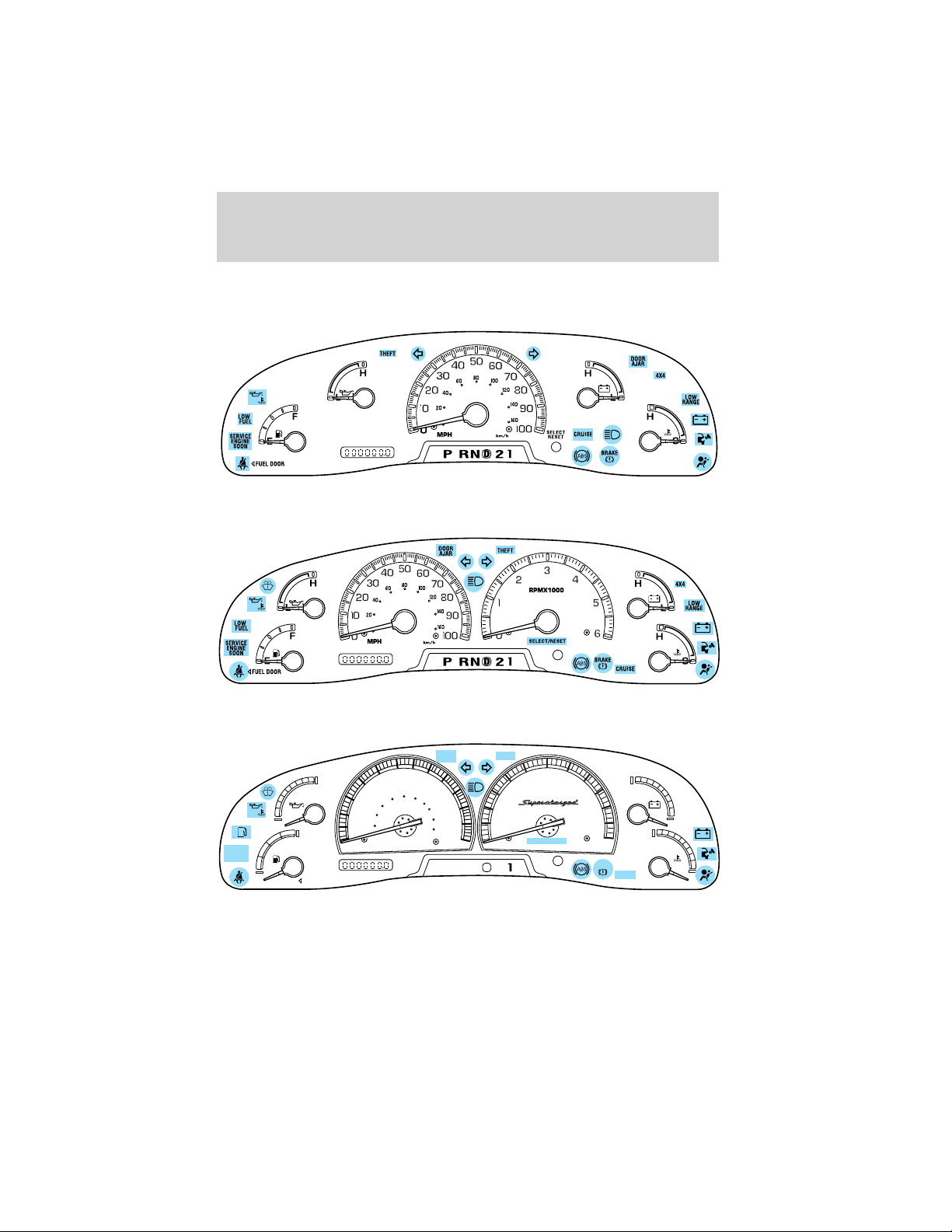
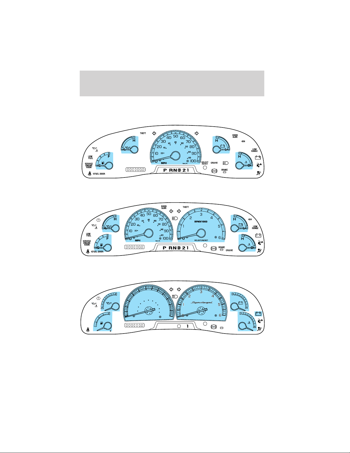
WARNING LIGHTS AND CHIMES
Standard instrument cluster
Optional instrument cluster
Harley—Davidson instrument cluster
SERVICE
ENGINE
SOON
DOOR
AJAR
60 70
80
50
H
L
F
E
PREMIUM
UNLEADED
FUEL ONLY
40
60
30
40
20
20
10
0
MPH
90
100
120
80
140
100
160
110
180
120
200
130
km/h
PRND2
THEFT
3
2
RPMX1000
1
0
SELECT/RESET
D
4
5
6
BRAKE
CRUISE
H
L
H
C
Warning lights and gauges can alert you to a vehicle condition that may
become serious enough to cause expensive repairs. A warning light may
illuminate when a problem exists with one of your vehicle’s functions.
12
Page 13
Instrument Cluster
Many lights will illuminate when you start your vehicle to make sure the
bulb works. If any light remains on after starting the vehicle, have the
respective system inspected immediately.
Service engine soon: If this light
illuminates while driving, it is a
possible indication that one of the
engine’s emission control systems
has failed.
Check fuel cap: Illuminates when
the fuel cap may not be properly
installed. Continued driving with
this light on may cause the Service
engine soon warning light to come
on.
Brake system warning light: To
confirm the brake system warning
light is functional, it will
momentarily illuminate when the
ignition is turned to the ON position when the engine is not running, or
in a position between ON and START, or by applying the parking brake
when the ignition is turned to the ON position. If the brake system
warning light does not illuminate at this time, seek service immediately
from your dealership. Illumination after releasing the parking brake
indicates low brake fluid level and the brake system should be inspected
immediately by your servicing dealership.
SERVICE
ENGINE
SOON
Driving a vehicle with the brake system warning light on is
dangerous. A significant decrease in braking performance may
occur. It will take you longer to stop the vehicle. Have the vehicle
checked by your dealer immediately.
Anti-lock brake system: If the
ABS light stays illuminated or
continues to flash, a malfunction has
been detected, have the system
serviced immediately. Normal
braking is still functional unless the brake warning light also is
illuminated.
ABS
13
Page 14
Instrument Cluster
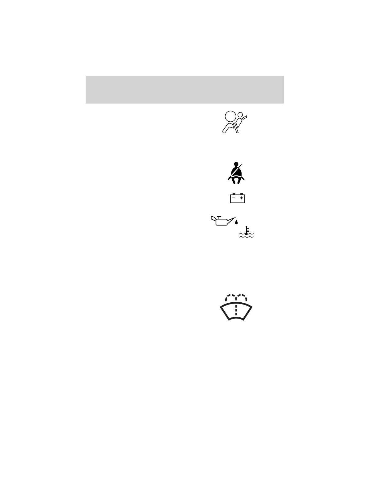
Air bag readiness: If this light fails
to illuminate when ignition is turned
to ON, continues to flash or remains
on, have the system serviced
immediately. A chime will also
sound when a malfunction in the supplemental restraint system has been
detected.
Safety belt: Reminds you to fasten
your safety belt. A chime will also
sound to remind you to fasten your
safety belt.
Charging system: Illuminates when
the battery is not charging properly.
Oil pressure/Engine coolant:
Illuminates when any of the
following conditions has occurred:
• The engine coolant temperature
is high.
• The engine oil pressure is low.
Low fuel: Illuminates when the fuel
level in the fuel tank is at, or near
empty (refer to Fuel gauge in this
chapter).
LOW
FUEL
Low washer fluid: Illuminates
when the windshield washer fluid is
low.
Speed control: Illuminates when
the speed control is activated. Turns
off when the speed control system
is deactivated.
14
CRUISE
Page 15
Instrument Cluster
Transmission control indicator
light (TCIL): Illuminates when the
overdrive function of the
transmission has been turned off,
refer to the Driving chapter. If the
light flashes steadily, have the system serviced immediately.
Four wheel drive low
(if equipped): Illuminates when
four-wheel drive low is engaged.
LOW
RANGE
OVERDRIVE
Four wheel drive indicator
(if equipped): Illuminates when
four-wheel drive is engaged.
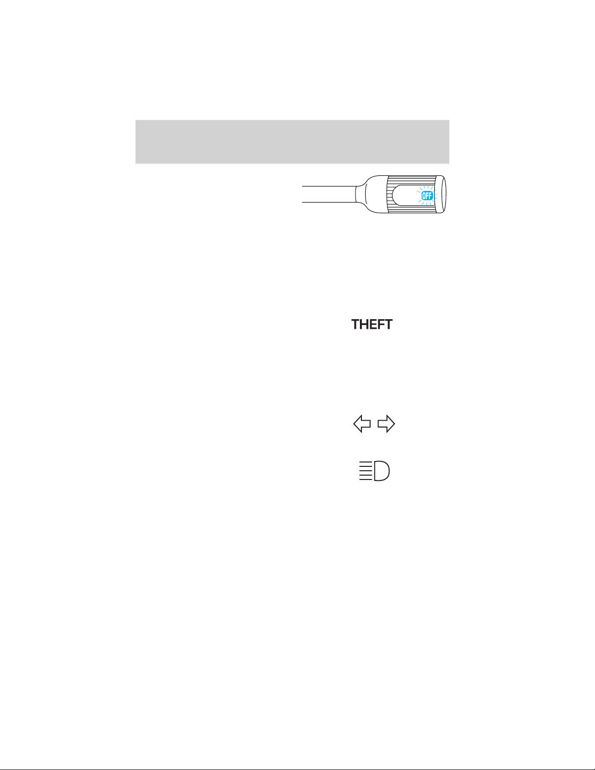
Anti-theft system (if equipped):
Flashes when the Securilock娂
Passive Anti-theft System has been
activated.
Door ajar: Illuminates when the
ignition is in the ON position and
any door is open.
4x4
DOOR
AJAR
Turn signal: Illuminates when the
left or right turn signal or the
hazard lights are turned on. If the
indicators stay on or flash faster, check for a burned out bulb.
High beams: Illuminates when the
high beam headlamps are turned on.
Key-in-ignition warning chime: Sounds when the key is left in the
ignition in the OFF/LOCK or ACC position and the driver’s door is
opened.
Headlamps on warning chime: Sounds when the headlamps or parking
lamps are on, the ignition is off (and the key is not in the ignition) and
the driver’s door is opened.
15
Page 16
Instrument Cluster
GAUGES
Standard instrument cluster gauges
Optional instrument cluster gauges
Harley—Davidson instrument cluster gauges
LOW
SERVICE
ENGINE
SOON
FUEL
DOOR
AJAR
60 70
80
H
L
F
E
PREMIUM
UNLEADED
FUEL ONLY
50
40
60
30
40
20
20
10
0
MPH
90
100
120
80
140
100
160
110
180
120
200
130
km/h
PRND2
THEFT
RPMX1000
SELECT/RESET
D
16
BRAKE
CRUISE
H
L
H
C
Page 17
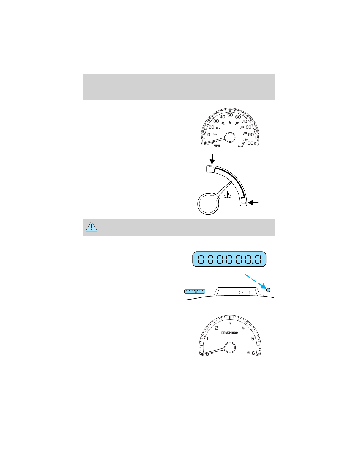
Speedometer: Indicates the
current vehicle speed.
Engine coolant temperature
gauge: Indicates engine coolant
temperature. At normal operating
temperature, the needle will be in
the normal range (between “H” and
“C”). If it enters the red section,
the engine is overheating. Stop
the vehicle as soon as safely
possible, switch off the engine
and let the engine cool.
Never remove the coolant reservoir cap while the engine is
running or hot.
Odometer: Registers the total
kilometers (miles) of the vehicle.
Instrument Cluster
H
C
Trip odometer: Registers the
kilometers (miles) of individual
journeys. Press the control once to
switch from the odometer to the
trip odometer. To reset the trip,
press the control again until the trip reading is 0.0 miles.
Tachometer (if equipped):
Indicates the engine speed in
revolutions per minute. Driving with
your tachometer pointer
continuously at the top of the scale
may damage the engine.
PRND2
D
17
Page 18
Instrument Cluster
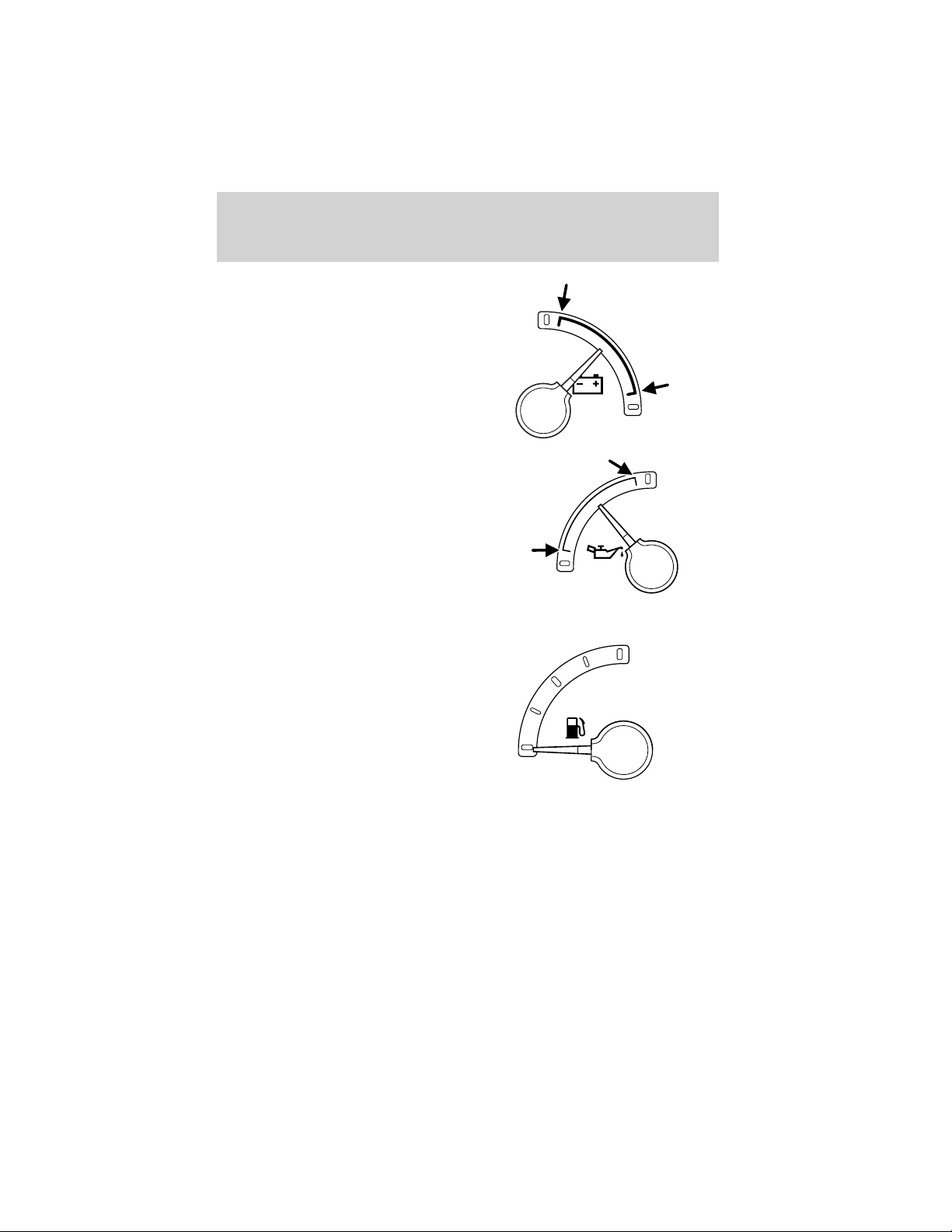
Battery voltage gauge: Indicates
the battery voltage when the
ignition is in the ON position. If the
pointer moves and stays outside the
normal operating range (as
indicated by arrows), have the
vehicle’s electrical system checked
as soon as possible.
Engine oil pressure gauge:
Indicates engine oil pressure. The
needle should stay in the normal
operating range (between “L” and
“H”). If the needle falls below the
normal range, stop the vehicle, turn
off the engine and check the engine
oil level. Add oil if needed. If the oil
level is correct, have your vehicle
checked at your dealership or by a
qualified technician.
Fuel gauge: Indicates
approximately how much fuel is left
in the fuel tank (when the ignition
is in the ON position).
H
L
H
L
F
18
E
Page 19
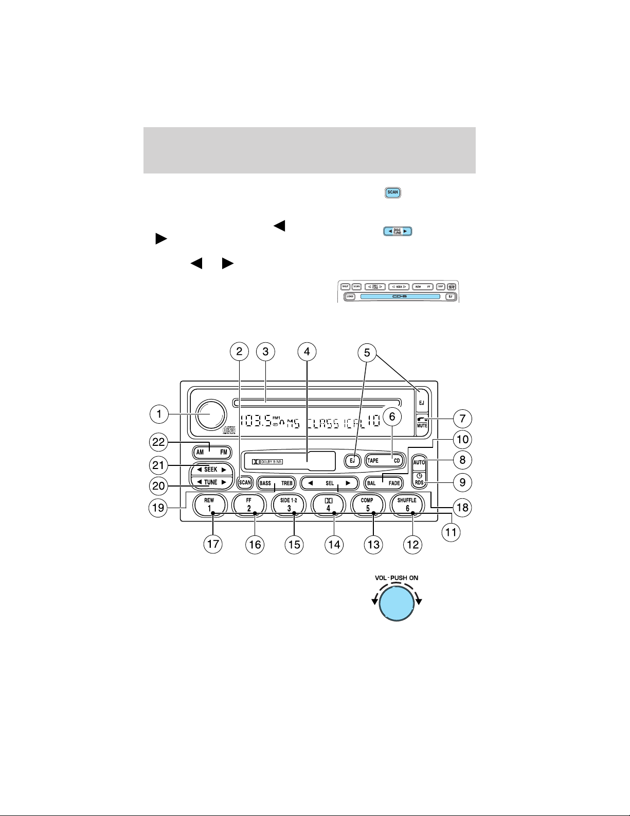
AM/FM STEREO CASSETTE
Entertainment Systems
12
VOL - PUSH ON
13 14 15 16 17 1 234
AM
BASS TREB BAL FADE
FM
11
10
SEEK
TUNE
SCAN
EJ
9
123456
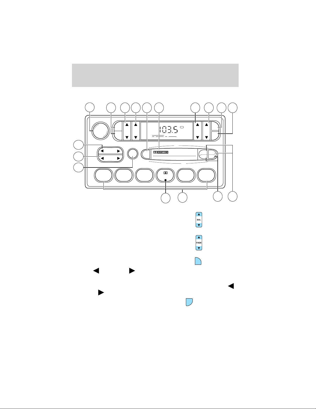
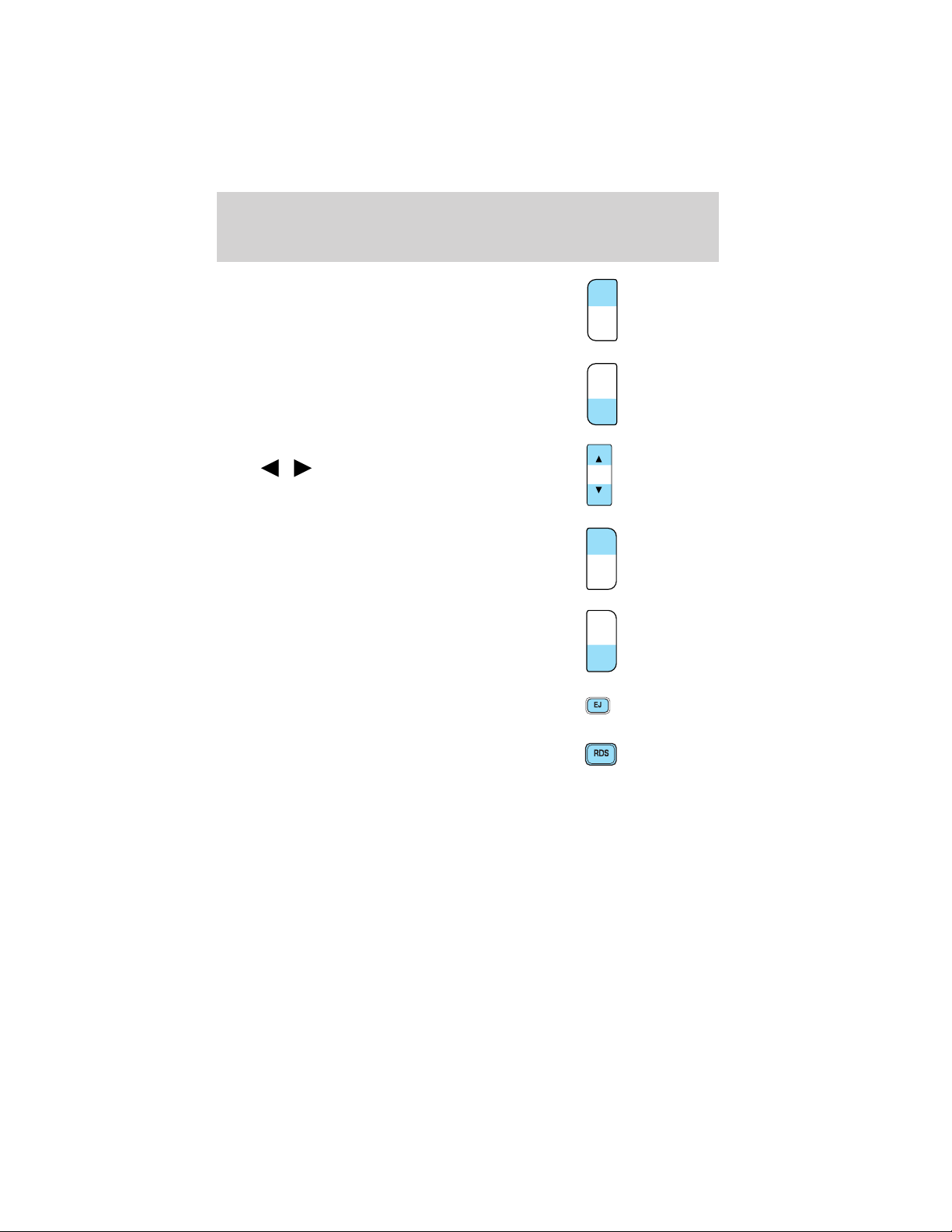
1. Balance: Press to shift sound to
the left/right speakers.
2. Fade: Press to shift sound to the
rear/front speakers.
FM1
ST
8
7
SIDE
REW FF
CLK
TAPE
AMS
1 - 2
65
3. CLK: To set the hour, press and
hold CLK. Then press SEEK to
decrease
or increase the
CLK
hours.
To set the minute, press and hold CLK and press TUNE to decrease
or increase the minutes.
4. Tape AMS: In tape mode, press
and hold to activate Automatic
TAPE
AMS
Music Search (allows you to quickly
locate the beginning of the tape selection being played or to skip to the
19
Page 20

Entertainment Systems
next selection). Then, press REW (for the beginning of the current
selection) or FF (to advance to the next selection). The tape MUST have
a blank section of at least four seconds duration between programs.
5. Side 1–2: Press to change tape
direction.
SIDE 1 - 2
6. REW (rewind): Press to rewind
REW
the tape.
FF (fast forward): Press to
FF
advance the tape.
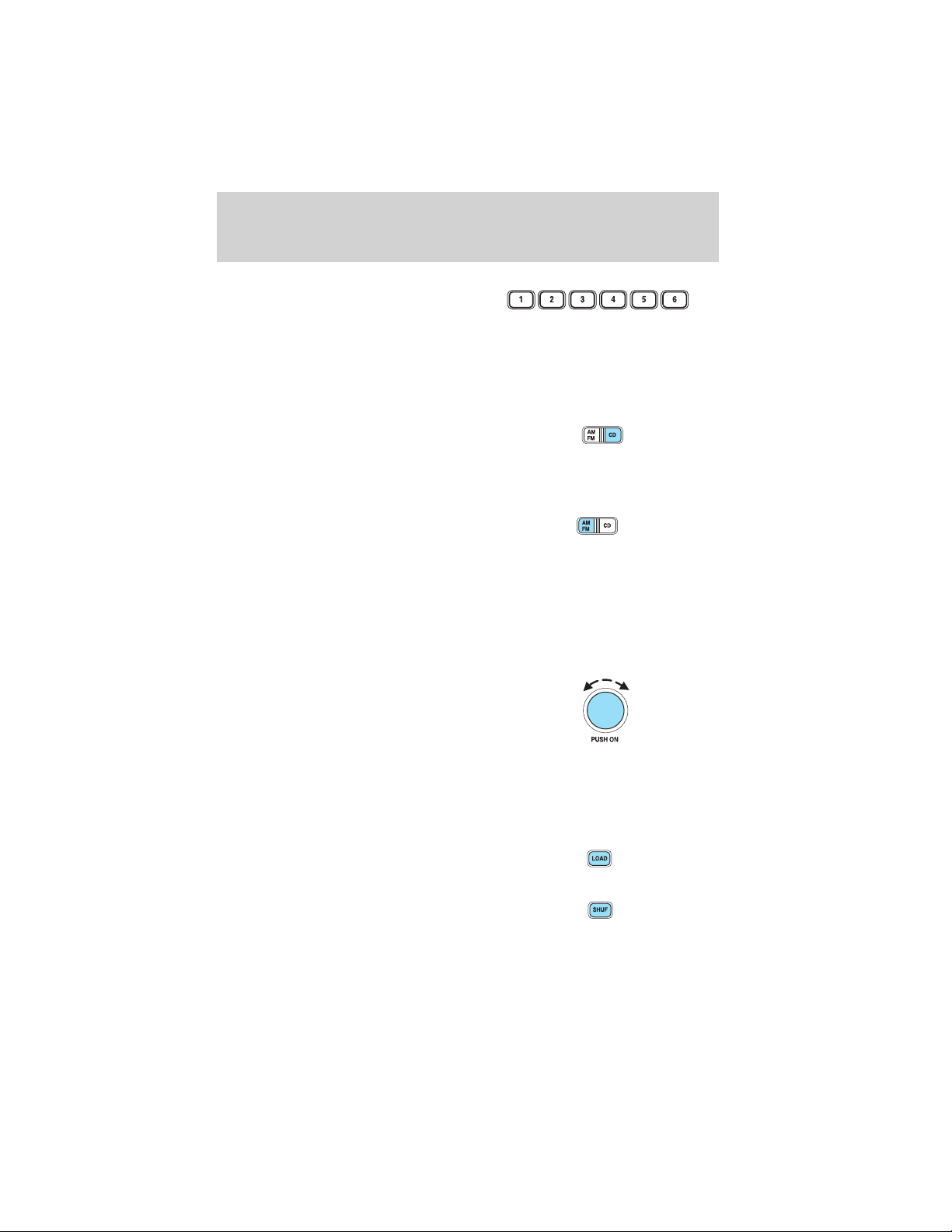
7. Memory preset buttons: To set
a station: Select frequency band
AM/FM1/FM2; tune to a station,
press and hold a preset button until sound returns.
Dolby威 noise reduction: Works in tape mode only. Reduces tape
8.
noise and hiss; press to activate/deactivate.
9. Scan: Press SCAN to hear a brief
sampling of all listenable radio
stations or all tape selections. Press
again to stop.
10. Tune: Works in radio mode only.
Press TUNE
/ to change
frequency down/up
11. Seek: Press and
release
/ for previous/next
strong station, selection or track.
12. Power/volume: Press to turn
ON/OFF; turn to increase or
decrease volume levels.
20
Page 21
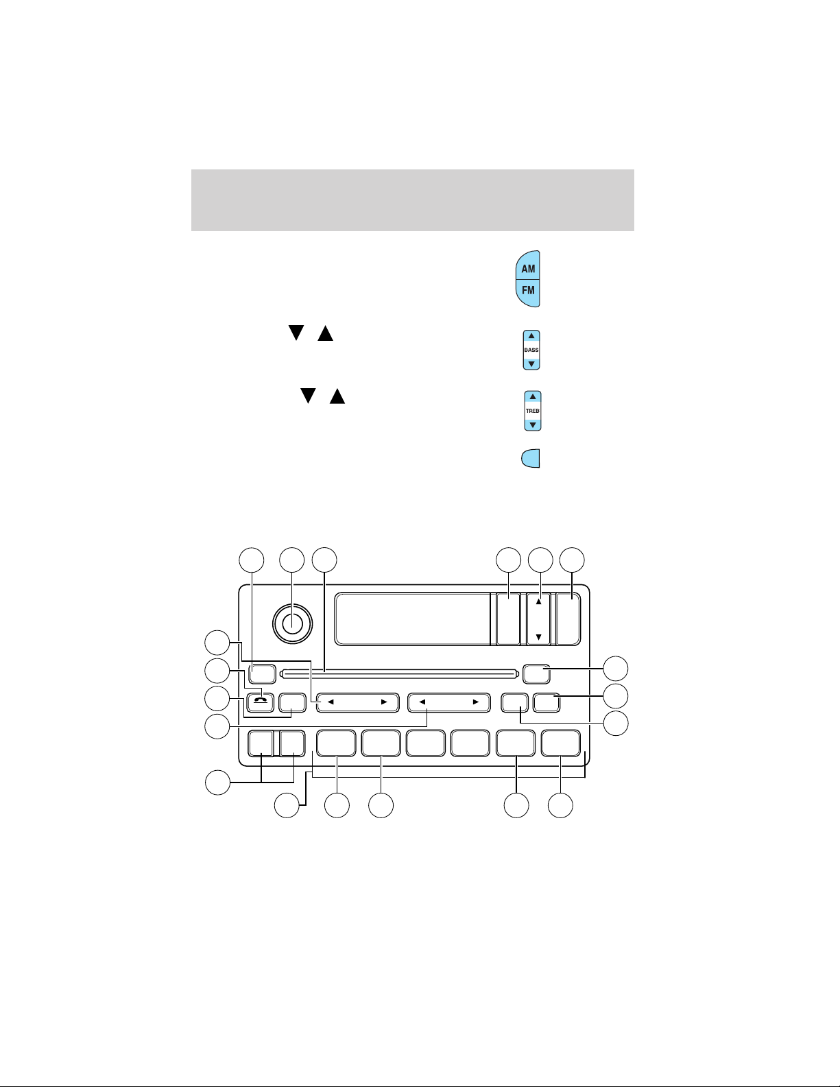
13. AM/FM: Press to choose a
frequency band in radio mode.
Entertainment Systems
14. Bass: Press
/ to
decrease/increase the bass output.
15. Treble: Press
/ to
decrease/increase the treble output.
16. EJ (Eject): Press to eject a
EJ
tape.
17. Cassette door: Insert a cassette into the cassette door.
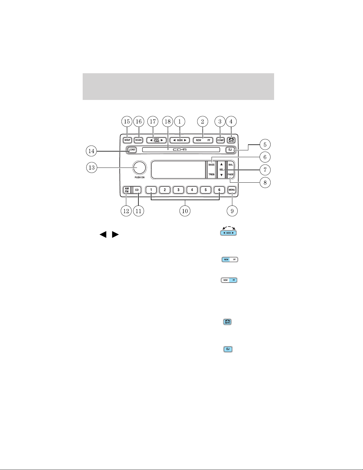
PREMIUM AM/FM STEREO/SINGLE CD RADIO
19
16
15
14
13
17
VOL
PUSH ON
MUTE
CD
18
SCAN
FMAM
REW
1
SEEK
FF
2 3 4
TUNE
2 3
1
BASS
SEL
TREB
EJ
RDS
AUTO
COMP5SHUFF
BAL
FADE
4
5
6
6
12
11
10
9
8
7
21
Page 22
Entertainment Systems
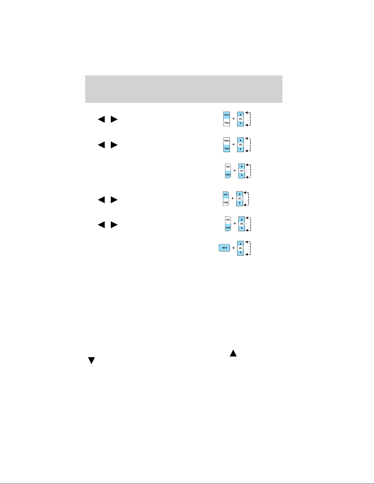
1. Bass: Press BASS and the press
SEL to increase/decrease the
amount of bass output.
Treble: Press TREB and then press
SEL to increase/decrease the
amount of treble output.
2. Select: Press and release
SEEK
/ for previous/next
strong station, selection or track.
3. Balance: Press BAL then press
SEL to shift the sound from to the
left/right speakers.
Fade: Press FADE then press SEL
to shift the sound from the
front/rear speakers.
4. Eject: Press to eject a CD.
BASS
TREB
BASS
TREB
SEL
BAL
FADE
BAL
FADE
5. RDS: Allows your audio system
to receive station identification or
program type from RDS-equipped
FM radio stations. Press RDS then press SEL to activate/deactivate:
Traffic: Allows you to hear traffic broadcasts. With the feature ON, press
SEEK or SCAN to find a station broadcasting a traffic report (if it is
broadcasting RDS data).Traffic information is not available in most
U.S. markets.
FIND Program type: Allows you to search RDS-equipped stations for a
certain category of music format: Classic, Country, Info, Jazz, Oldies,
R&B, Religious, Rock, Soft, Top 40.
Show TYPE: Displays the station’s call letters and format.
22
Page 23
Entertainment Systems
Setting the clock: Press RDS until SELECT HOUR or SELECT MINS is
displayed. Use the SEL control to manually increase/decrease (
the time.
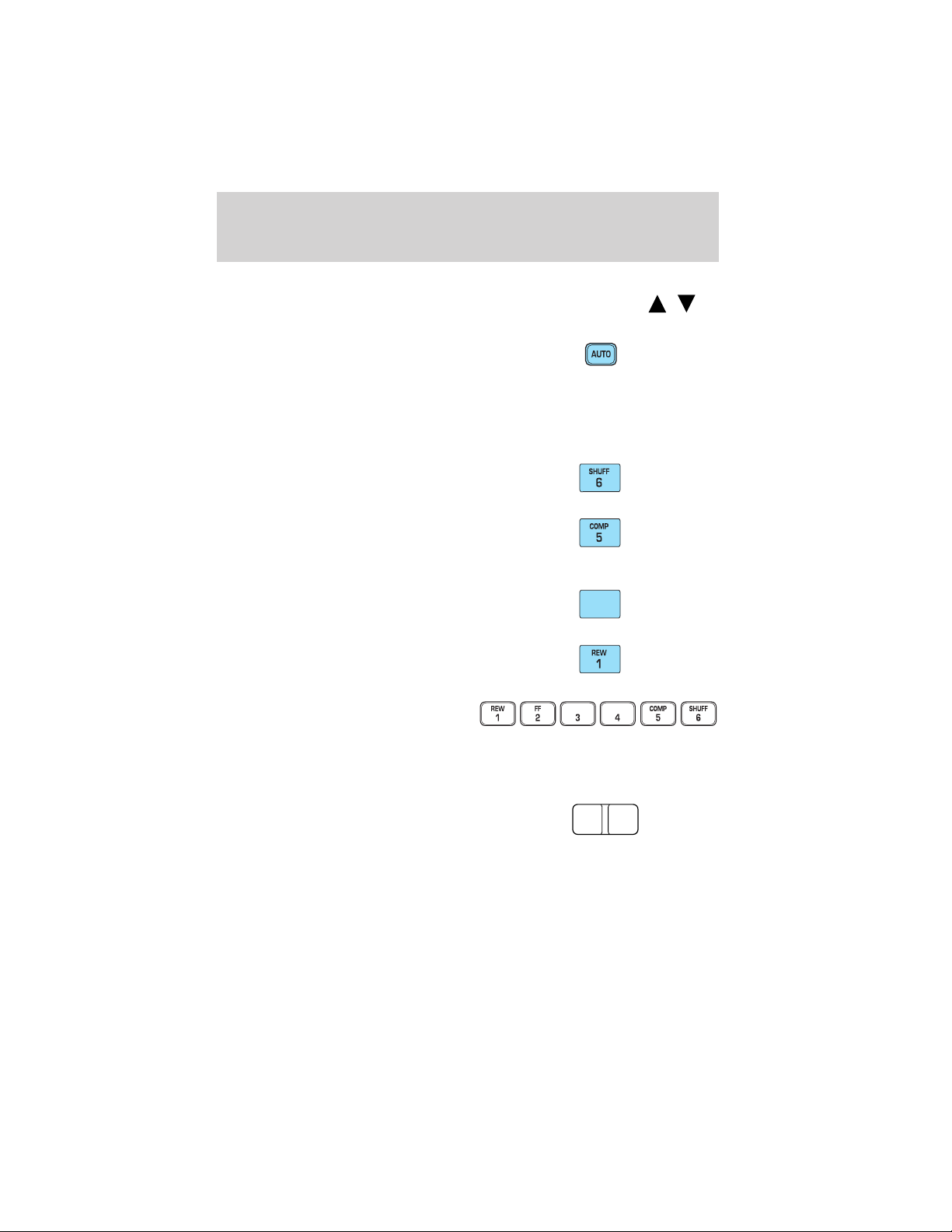
6. AUTO: Allows you to set strong
radio stations without losing your
original manually set preset stations.
Select a frequency and press AUTO. Once the six strongest stations are
filled, the station stored in memory 1 will begin to play.
To deactivate autoset and return to your audio system’s manually set
memory stations, press the control again.
7. Shuffle: Press to play the CD
tracks in random order.
8. Compression: Compression
adjust brings soft and loud CD
passages together for a more
consistent listening level. Press to activate/deactivate.
9. Fast forward: Press to advance
on the CD. Press and hold for a
FF
2
more fast advance.
10. Rewind: Press for a slow
rewind. Press and hold for a fast
rewind.
11. Memory presets: These
controls can be used to select up to
six preset AM stations and twelve
FM stations (six in FM1 and six in FM2).
Select the desired station. Press and hold the memory preset control
until the sound returns indicating it has been saved.
12. AM/FM: Press to select from
the AM/FM frequency bands.
AM FM
/ )
23
Page 24

Entertainment Systems
13. Tune: Press to manually move
up
or down the frequency
TUNE
band or to the next/previous CD in
the CD changer (if equipped).
14. Scan: Press to hear a brief
SCAN
sampling of radio stations or CD
tracks.
15. Mute: Press to mute the playing
media.
16. Seek: Press to listen to the
previous
or next listenable
SEEK
radio station or CD track.
17. CD: Press to enter CD mode if
in another mode. Press CD to begin
CD play if a CD is already loaded
into the system.
18. Power/volume: Press to turn
on/off; turn to increase or decrease
volume levels.
Speed sensitive volume
(if equipped): Radio volume changes
automatically and slightly with vehicle speed to compensate for road and
wind noise. Press and hold the volume control for five seconds, then
press SEL to increase or decrease compensation.
19. CD door: Insert a CD, label side up.
24
Page 25
Entertainment Systems
PREMIUM IN-DASH SIX CD SOUND SYSTEM
1. Seek: Press and release
SEEK
strong station, or track of current
disc.
2. Rewind: Press for a slow rewind,
press and hold for a fast rewind.
/ for previous/next
Fast forward: Press for a slow
advance, press and hold for a fast
advance.
3. Comp (Compression): In CD mode, press to adjust the soft and loud
passages together for a more consistent listening level. Press the COMP
control until COMP ON is displayed.
4. Mute: Press to MUTE playing
media; press again return to playing
media. In CD mode, MUTE acts as a
pause feature.
5. Eject: Press to eject a CD. Press
and hold to auto eject all loaded
discs.
25
Page 26
Entertainment Systems
6. Bass: Press BASS; then press
SEL
the bass output.
Treble: Press TREB; then press
SEL
the treble output.
7. Select: Use with Bass, Treble,
Balance and Fade controls to adjust
levels. Use with MENU to set the
clock and engage RDS.
8. Balance: Press BAL; then press
SEL
left/right speakers.
Fade: Press FADE; then press
SEL
rear/front speakers.
9. Menu: Press MENU and SEL to
access clock mode, RDS on/off,
Traffic, Program type, Show type
and Compression modes.
Traffic: Allows you to hear traffic broadcasts. With the feature ON, press
SEEK or SCAN to find a station broadcasting a traffic report (if it is
broadcasting RDS data). Traffic information is not available in most
U.S. markets.
FIND Program type: Allows you to search RDS-equipped stations for a
certain category of music format: Classic, Country, Info, Jazz, Oldies,
R&B, Religious, Rock, Soft, Top 40.
Show TYPE: Displays the station’s call letters and format.
Compression: Brings soft and loud CD passages together for a more
consistent listening level.
Setting the clock: Press MENU until SELECT HOUR or SELECT
MINUTE is displayed. Use SEL to manually increase (
(
/ to decrease/increase
/ to decrease/increase
/ to shift sound to the
/ to shift sound to the
) or decrease
) the hours/minutes. Press MENU again to disengage clock mode.
26
Page 27
Entertainment Systems
10. Memory presets: To set a
station: Select frequency band
AM/FM; tune to a station, press and
hold a preset button until sound
returns. In CD mode, press to move between CDs.
This radio is equipped with six station memory preset controls which
allow you to set up to six AM stations and 12 FM stations (six in FM1
and six in FM2).
11. CD: Press to select CD mode.
Seamless play: In CD mode, the
transition between the end of one
CD and the beginning of another will not contain delay time unless SEEK
or a preset control is pressed.
12. AM/FM: Press to select a
frequency band in radio mode.
Autostore: Allows you to set the
strongest local radio stations without losing your original manually set
preset stations for AM/FM1/FM2 . Press and momentarily hold AM/FM.
AUTOSTORE will flash on the display. When the six strongest stations
are filled, the station stored in preset 1 will begin playing. If there are
less than six strong stations, the system will store the last one in the
remaining presets. Press again to disengage.
13. Power/volume: Press to turn
ON/OFF; turn to increase or
decrease volume levels.
Speed sensitive volume
(if equipped): Radio volume
changes automatically and slightly
with vehicle speed to compensate for road and wind noise. Press and
hold the volume control for five seconds (with the radio on). SPEED
VOL will appear in the display, then press SEL to increase/decrease the
compensation.
14. Load: Press to load a CD. Press
and hold to load up to six discs.
15. Shuffle: Press to play tracks in
random order. Press SHUF to cycle
through SHUF DISC, SHUF TRAC or
SHUF OFF.
27
Page 28
Entertainment Systems
16. Scan: Press to hear a brief
sampling of all listenable stations or
CD tracks. Press again to stop.
17. Disc/Tune: Radio: Press
or to manually tune down or up
the frequency band.
CD: Press
18. CD door: Insert a CD label side
up.
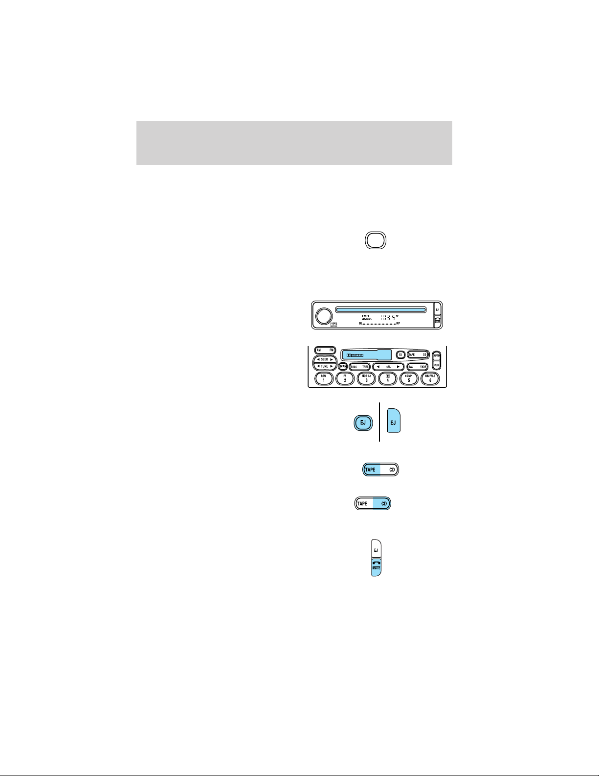
PREMIUM AM/FM STEREO/CASSETTE/SINGLE CD
or to select the previous or next track on the CD.
1. Power/volume: Press to turn
ON/OFF; turn
clockwise/counterclockwise to
increase/decrease volume.
28
Page 29
Entertainment Systems
Speed sensitive volume
(if equipped): Radio volume automatically changes with vehicle speed to
compensate for road and wind noise. Press and hold the volume control
until the display reads SPEED VOL appears in the display. Then press
SEL to increase or decease the compensation.
2. Scan: Press SCAN to move up
the radio frequency band. SCAN
automatically finds a station, plays it
for five seconds, then moves to the next station. Press again to stop.
Tape/CD: Press SCAN to sample tape/CD selections for eight seconds.
Press again to stop.
3. CD Door: Insert the disc with
the playing side down and printed
side up.
4. Cassette door: Insert the
cassette with the opening to the
right.
5. Eject: Press to eject the
cassette/CD. The radio will resume
playing.
SCAN
6. Tape: Press to stop tape during
rewind/fast forward.
CD: Press to start CD play. With the
dual media audio, press CD to
toggle between single CD and CD
changer play.
7. Mute: Press to MUTE playing
media; press again return to playing
media.
29
Page 30
Entertainment Systems
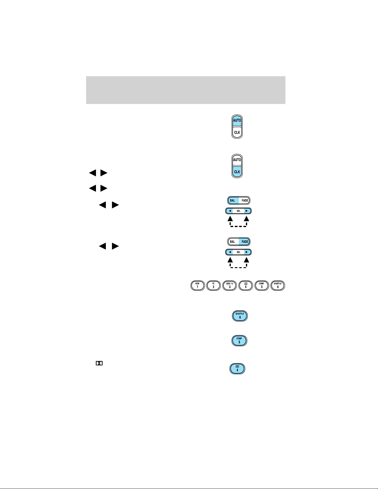
8. Auto: Press to set first six strong
stations into AM, FM1 or FM2
memory buttons; press again to
return to normal stations.
9. CLK: Press and hold to set the
clock.
Press SEEK to decrease/increase
/ ) the hours.
(
Press TUNE to decrease/increase
/ ) the minutes.
(
10. Balance: Press BAL; then press
SEL
left/right speakers.
Fade: Press FADE; then press
SEL
rear/front speakers.
/ to shift sound to the
/ to shift sound to the
11. Memory preset buttons: To
set a station: Select frequency band
AM/FM; tune to a station, press and
hold a preset button until sound returns.
12. Shuffle (CD): Press to play
tracks in random order.
13. Compression (CD): Press to
bring soft and loud passages
together for a more consistent
listening level.
14.
Reduces tape noise and hiss; press
to activate/deactivate.
30
Dolby威 noise reduction:
Page 31

15. Side 1–2: Press to play reverse
side of the tape.
Entertainment Systems
16. Fast Forward (FF): Press to
fast forward the tape.
17. Rewind (REW): Press to
rewind the tape.
18. Select (SEL): Use with Bass,
Treble, Balance and Fade controls.
19. Bass: Press BASS; then press
SEL
/ to decrease/increase
the bass output.
Treble: Press TREB; then press
SEL
/ to decrease/increase
the treble output.
20. Tune: Works in radio mode only.
Press TUNE
/ to change
frequency down/up.
FF
2
SEEK
TUNE
REW
1
SEL
21. Seek: Press and release
SEEK
/ for previous/next
strong station, selection or track.
SEEK
TUNE
31
Page 32

Entertainment Systems
22. AM/FM: Press to select AM/FM
frequency band.
REAR AUDIO CONTROLS (IF EQUIPPED)
The rear seat controls allow the rear seat passengers to operate the
radio, tape, CD or CD changer or in-vehicle entertainment system mode
(if equipped).
To engage, simultaneously press the memory preset controls 3 and 5.
Press again to disengage.
1. Mode: Push to toggle between
AM, FM1, FM2, tape, CD or CD
changer mode (if equipped).
2. Memory: Push successively to
allow rear seat passengers to scroll
through memory presets. Push in
CD changer mode (if equipped) to
advance to the next disc.
3. Headphone jack: Plug a 3.5 mm
headphone into the jack.
4. Headphone/speaker: Press to turn all speakers off (headphone
mode). Press again to deactivate the headphone and activate system
speakers.
5. Seek: Press
or track.
6. Volume: Press + to increase and — to decrease volume levels. From
the rear seat controls, volume can not be set higher than the front seat
setting.
or to access the previous or next station, selection
32
Page 33

Entertainment Systems
RADIO FREQUENCIES
AM and FM frequencies are established by the Federal Communications
Commission (FCC) and the Canadian Radio and Telecommunications
Commission (CRTC). Those frequencies are:
AM - 530, 540–1600, 1610 kHz
FM- 87.7, 87.9–107.7, 107.9 MHz
RADIO RECEPTION FACTORS
There are three factors that can effect radio reception:
• Distance/strength: The further you travel from an FM station, the
weaker the signal and the weaker the reception.
• Terrain: Hills, mountains, tall buildings, power lines, electric fences,
traffic lights and thunderstorms can interfere with your reception.
• Station overload: When you pass a broadcast tower, a stronger signal
may overtake a weaker one and play while the weak station frequency
is displayed.
CASSETTE/PLAYER CARE
Do:
• Use only cassettes that are 90 minutes long or less.
• Tighten very loose tapes by inserting a finger or pencil into the hole
and turning the hub.
• Remove loose labels before inserting tapes.
• Allow tapes which have been subjected to extreme heat, humidity or
cold to reach a moderate temperature before playing.
• Clean the cassette player head with a cassette cleaning cartridge after
10–12 hours of play to maintain good sound/operation.
Don’t:
• Expose tapes to direct sunlight, extreme humidity, heat or cold.
• Leave tapes in the cassette player for a long time when not being
played.
33
Page 34

Entertainment Systems
CD/CD PLAYER CARE
Do:
• Handle discs by their edges only. Never touch the playing surface.
• Inspect discs before playing. Clean only with an approved CD cleaner
and wipe from the center out.
Don’t:
• Expose discs to direct sunlight or heat sources for extended periods
of time.
• Insert more than one disc into each slot of the CD changers.
• Clean using a circular motion.
CD units are designed to play commercially pressed 12 cm (4.75
in) audio compact discs only. Due to technical incompatibility,
certain recordable and re-recordable compact discs may not
function correctly when used in Ford CD players. Irregular
shaped CDs, CDs with a scratch protection film attached, and CDs
with homemade paper (adhesive) labels should not be inserted
into the CD player. The label may peel and cause the CD to
become jammed. It is recommended that homemade CDs be
identified with permanent felt tip marker rather than adhesive
labels. Ball point pens may damage CDs. Please contact your
dealer for further information.
AUDIO SYSTEM WARRANTY AND SERVICE
Refer to the Warranty Guide for audio system warranty information. If
service is necessary, see your dealer or qualified technician.
34
Page 35

Climate Controls
HEATER ONLY SYSTEM
(IF EQUIPPED)
1. Fan speed adjustment: Controls
the volume of air circulated in the
vehicle.
2. Temperature selection:
Controls the temperature of the
airflow in the vehicle.
3. Air flow selections: Controls the direction of the airflow in the
vehicle. See the following for a brief description on each control.
: Distributes outside air through the instrument panel vents.
O (OFF): Outside air is shut out and the fan will not operate.
: Distributes outside air through the instrument panel vents and the
floor vents.
: Distributes outside air through the floor vents.
: Distributes outside air through the windshield defroster vents and
floor vents.
: Distributes outside air through the windshield defroster vents.
OPERATING TIPS
• To reduce fog build up on the windshield during humid weather, place
the air flow selector in the
• To reduce humidity build up inside the vehicle during cold or warm
weather, do not drive with the air flow selector in the OFF position.
• Under normal weather conditions, do not leave the air flow selector in
OFF when the vehicle is parked. This allows the vehicle to “breathe”
using the outside air inlet vents.
• Do not put objects under the front seats that will interfere with the air
flow to the back seats.
• Remove any snow, ice or leaves from the air intake area at the base of
the windshield.
To aid in side window defogging/demisting in cold weather:
1. Select
2. Set the temperature control to full heat
3. Set the fan speed to HI
position.
35
Page 36

Climate Controls
4. Direct the outer instrument panel vents towards the side windows
To increase airflow to the outer instrument panel vents, close the vents
located in the middle of the instrument panel.
Do not place objects on top of the instrument panel as these
objects may become projectiles in a collision or sudden stop.
MANUAL HEATING AND AIR
CONDITIONING SYSTEM
1. Fan speed adjustment: Controls
the volume of air circulated in the
vehicle.
2. Temperature selection:
Controls the temperature of the
airflow in the vehicle.
3. Air flow selections: Controls the direction of the airflow in the
vehicle. See the following for a brief description on each control.
MAX A/C: Uses recirculated air to cool the vehicle. Air flows from the
instrument panel vents only.
A/C: Uses outside air to cool the vehicle. Air flows from the instrument
panel vents only.
: Distributes outside air through the instrument panel vents.
O (OFF): Outside air is shut out and the fan will not operate.
: Distributes outside air through the instrument panel vents and the
floor vents.
: Distributes outside air through the floor vents.
: Distributes outside air through the windshield defroster vents and
floor vents.
: Distributes outside air through the windshield defroster vents.
36
Page 37

Climate Controls
OPERATING TIPS
• To reduce fog build up on the windshield during humid weather, place
the air flow selector in the
• To reduce humidity build up inside the vehicle: do not drive with the
air flow selector in the OFF or MAX A/C position.
• Under normal weather conditions, do not leave the air flow selector in
MAX A/C or OFF when the vehicle is parked. This allows the vehicle
to “breathe” using the outside air inlet vents.
• Do not put objects under the front seats that will interfere with the
airflow to the back seats.
• Remove any snow, ice or leaves from the air intake area at the base of
the windshield.
To aid in side window defogging/demisting in cold weather:
1. Select
2. Select A/C
3. Modulate the temperature control to maintain comfort.
4. Set the fan speed to HI
5. Direct the outer instrument panel vents towards the side windows
To increase airflow to the outer instrument panel vents, close the vents
located in the middle of the instrument panel.
position.
Do not place objects on top of the instrument panel as these
objects may become projectiles in a collision or sudden stop.
37
Page 38

Climate Controls
ELECTRONIC AUTOMATIC TEMPERATURE CONTROL (EATC)
SYSTEM
1. OFF: Press to turn the system
OFF.
2. AUTOMATIC: Press to engage
automatic mode. The system will
determine fan speed, airflow
location, and outside or recirculated air depending on the selected
temperature. Fan speed will remain automatic unless the thumbwheel is
turned.
Rear defrost
windshield.
3. Fan speed: Turn to manually
increase or decrease fan speed.
38
(if equipped): Removes ice and fog from the rear
Page 39

Climate Controls
4. Defrost: Distributes outside air through the windshield defroster
vents.
5. Floor/defrost: Distributes outside air through the windshield
defroster and floor vents.
6. Floor: Distributes outside air through the floor vents.
7. Panel/floor: Distributes outside air through the instrument panel and
floor vents.
8. Vent: Distributes outside air through the instrument panel vents and
the floor vents.
9. Max A/C: Distributes recirculated air through the instrument panel
vents to cool the vehicle.
10. Manual override controls:
Press any of these controls to leave
automatic mode and to manually
determine where airflow is directed. To return to full automatic control,
press AUTO.
11. Outside Temp: Press to display
the outside temperature. Will remain
in the display until pressed again.
The temperature will be most accurate when the vehicle is in motion.
AUTO: Press to engage automatic mode. The system will determine fan
speed, airflow location, and outside or recirculated air depending on the
selected temperature. Fan speed will remain automatic unless the
thumbwheel is turned.
12. Temperature controls: Press
to increase or decrease the desired
temperature. In automatic mode, the
system will determine the fan speed,
airflow location, outside or recirculated air to heat or cool the vehicle to
the selected temperature.
13. EXT: Press to display the outside temperature. This temperature will
remain in the display until pressed again. The temperature will be most
accurate when the vehicle is in motion.
39
Page 40

Climate Controls
OPERATING TIPS
• To reduce fog build up on the windshield during humid weather, place
the air flow selector in the
• To reduce humidity build up inside the vehicle: do not drive with the
air flow selector in the OFF or MAX A/C position.
• Under normal weather conditions, do not leave the air flow selector in
MAX A/C or OFF when the vehicle is parked. This allows the vehicle
to “breathe” using the outside air inlet vents.
• Do not put objects under the front seats that will interfere with the
airflow to the back seats.
• Remove any snow, ice or leaves from the air intake area at the base of
the windshield.
To aid in side window defogging/demisting in cold weather:
1. Select
2. Select A/C
3. Modulate the temperature control to maintain comfort.
4. Set the fan speed to HI
5. Direct the outer instrument panel vents towards the side windows
To increase airflow to the outer instrument panel vents, close the vents
located in the middle of the instrument panel.
position.
Do not place objects on top of the instrument panel as these
objects may become projectiles in a collision or sudden stop.
REAR WINDOW DEFROSTER (IF EQUIPPED)
The rear defroster control is located on the climate control panel and
works to defrost your windshield from fog and ice.
Ensure that the ignition is ON position. Press to turn the defroster
ON/OFF. The indicator light will illuminate when ON.
40
Page 41

Lights
HEADLAMP CONTROL
Turns the lamps off.
Turns on the parking lamps,
instrument panel lamps, license
plate lamps and tail lamps.
Turns the headlamps on.
Autolamp control (if equipped)
The autolamp system sets the
headlamps to turn on and off
automatically. It also keeps the
lights on for approximately 20
seconds after the ignition switch is
turned to the OFF position.
• To turn autolamps on, rotate the
control counterclockwise.
• To turn autolamps off, rotate the
control clockwise to the OFF
position.
• Foglamps are not controlled by the autolamps. In order to turn on the
foglamps, you must turn the lamp switch to the
pull toward you for foglamps.
A
A
position and
Foglamp control (if equipped)
The foglamps can be turned on only
when the headlamp control is in
the
position and the high
beams are not turned on.
Pull headlamp control towards you
to turn foglamps on. The foglamp
indicator light
will illuminate.
A
41
Page 42

Lights
Daytime running lamps (DRL) (if equipped)
Turns the headlamps on with a reduced output.
To activate:
• the ignition must be in the ON position and
• the headlamp control is in the OFF, parking lamp or autolamp
position.
Always remember to turn on your headlamps at dusk or during
inclement weather. The Daytime Running Lamp (DRL) system
does not activate with your tail lamps and generally may not provide
adequate lighting during these conditions. Failure to activate your
headlamps under these conditions may result in a collision.
High beams
Push the lever toward the
instrument panel to activate. Pull
the lever towards you to deactivate.
Flash to pass
Pull toward you slightly to activate
and release to deactivate.
42
Page 43

Lights
PANEL DIMMER CONTROL
Use to adjust the brightness of the
instrument panel and all applicable
switches in the vehicle during
headlamp and parklamp operation.
Move the control to the full upright
position, past detent, to turn on the
interior lamps.
Move the control to the full down
position, past detent, to turn off the
interior lamps.
AIMING THE HEADLAMPS
The headlamps on your vehicle are properly aimed at the assembly plant.
If your vehicle has been in an accident the alignment of your headlamps
should be checked by a qualified service technician.
TURN SIGNAL CONTROL
• Push down to activate the left
turn signal.
• Push up to activate the right turn
signal.
43
Page 44

Lights
INTERIOR LAMPS
Map lamps
To turn on the map lamps, press the
control next to each lamp.
If equipped with a moon roof, press
the control next to the map lamp to
illuminate the lamp.
AUTO
ROOF
Rear dome lamp (if equipped)
The dome lamp lights when the
control is in the DOOR (left)
position, any door is open, the
instrument panel switch is pushed
past the detent and when any of the
remote entry controls are pressed
while the ignition is off.
The rear dome lamp can be turned
ON (center) or OFF (right) by sliding the control.
44
Page 45

Courtesy/reading lamps
The dome lamp lights when the
control is in the DOOR (left)
position, any door is open, the
instrument panel switch is pushed
past the detent and when any of the
remote entry controls are pressed
while the ignition is off.
The reading lamps can be turned on
by pressing the rocker controls next
to each lamp.
Rear door lamps (if equipped)
The dome lamp lights when the
control is in the DOOR (left)
position, any door is open, the
instrument panel switch is pushed
past the detent and when any of the
remote entry controls are pressed
while the ignition is off.
The rear door lamps can be turned
on by pressing the rocker controls
next to each lamp.
Lights
BULBS
Replacing exterior bulbs
Check the operation of all the bulbs frequently.
Using the right bulbs
Replacement bulbs are specified in the chart below. Headlamp bulbs
must be marked with an authorized “D.O.T.” for North America and an
“E” for Europe to assure lamp performance, light brightness and pattern
and safe visibility. The correct bulbs will not damage the lamp assembly
or void the lamp assembly warranty and will provide quality bulb burn
time.
45
Page 46

Lights
Function Number of
Trade number
bulbs
Headlamps 2 9007
Front park/turn lamps 2 3157AK (amber)
Foglamps 2 9145
1
Backup lamp 2 3156K
Rear stop/turn/sidemarker/tail
2 3457K
lamp
High-mount brakelamp 1 912
Cargo lamp 2 912
License plate lamp 2 168
Signal mirror lamp (if equipped) 2 906/921
Running board lamp (if equipped) 4 168
All replacement bulbs are clear in color except where noted.
To replace all instrument panel lights - see your dealer
1
Harley Davidson package uses bulb number H1 12V
Replacing headlamp bulbs
1. Make sure that the headlamp control is in the OFF position and open
the hood.
2. At the back of the headlamp, pull
clips rearward and up (about
3
⁄
4
inch) to release the headlamp
assembly.
3. Slide headlamp assembly forward
and disconnect the electrical
connector from the bulb by pulling
rearward.
46
Page 47

Lights
4. Remove bulb retainer ring by
turning it counterclockwise, then
slide the ring off the plastic base.
5. Carefully pull bulb assembly out
of headlamp assembly and replace.
Handle a halogen headlamp bulb carefully and keep out of
children’s reach. Grasp the bulb only by its plastic base and do
not touch the glass. The oil from your hand could cause the bulb to
break the next time the headlamps are operated.
Install the new bulb in reverse order.
Replacing front parking lamp/turn signal bulbs
1. Make sure the headlamp control
is in the OFF position and open the
hood.
2. Remove screw from the lamp
assembly and disengage lamp
assembly by pulling straight forward,
to disengage two hidden snap-in
retainers.
47
Page 48

Lights
3. Remove bulb socket from the
parking lamp assembly by turning it
counterclockwise.
4. Pull bulb straight out of socket
and press in the new bulb.
Install the new bulb(s) in reverse order.
Replacing tail/brake/turn signal/backup lamp bulbs
1. Make sure the headlamp control
is in the OFF position.
2. Open the liftgate to expose the
lamp assembly screws and remove
the two bolts from the tail lamp
assembly.
3. Carefully pull the lamp assembly
straight rearward from the tailgate
pillar to disengage two hidden snap-in retainers. (Flare side and Super
Crew tail lamps are not equipped with snap-in retainers.)
4. Remove bulb socket from the lamp assembly by turning it
counterclockwise.
5. Pull bulb straight out of socket and press in the new bulb.
Install the new bulb(s) in reverse order.
48
Page 49

Replacing high-mount brake and cargo lamp bulbs
Make sure the headlamp control is
in the OFF position.
1. Remove the two screws and move
the lamp assembly away from the
vehicle to expose the bulb sockets.
2. Remove the bulb socket by
rotating counterclockwise and
pulling it out of the lamp assembly.
3. Pull the bulb straight out of the
socket and push in the new bulb.
Install the new bulbs in reverse
order.
Replacing foglamp bulbs (if equipped)
1. Make sure the headlamp control
is in the OFF position.
2. Remove the bulb socket from the
foglamp by turning
counterclockwise.
3. Disconnect the electrical connector from the foglamp bulb.
Install the new bulb in reverse order.
Replacing signal mirror lamp bulbs (if equipped)
For bulb replacement, see a dealer or qualified technician.
Lights
49
Page 50

Lights
Replacing license plate lamp bulbs
The license plate bulbs are located
behind the rear bumper. To change
the license plate lamp bulbs:
1. Reach behind the rear bumper to
locate the bulb.
2. Twist the bulb socket
counterclockwise and carefully pull
to remove it from the lamp
assembly.
3. Pull out the old bulb from the
socket and push in the new bulb.
4. Install the bulb socket in lamp assembly by turning it clockwise.
Replacing running board lamp bulbs (if equipped)
The running board bulbs are located
behind the running board.
1. Reach behind the center bracket
of the running board to locate the
bulb.
2. Twist the bulb socket
counterclockwise and carefully pull
to remove it from the lamp
assembly.
3. Pull out the old bulb from the
socket and push in the new bulb.
Install the new bulb in reverse order.
50
Page 51

Driver Controls
MULTI-FUNCTION LEVER
Windshield wiper: Rotate the end
of the control away from you to
increase the speed of the wipers;
rotate towards you to decrease the
speed of the wipers.
Speed dependent wipers: When
the wiper control is on, the speed of
the wipers will automatically adjust
with the vehicle speed. The faster your vehicle is travelling the faster the
wipers will go.
Windshield washer: Push the end
of the stalk:
• briefly: causes a single swipe of
the wipers without washer fluid.
• a quick push and hold: the wipers
will swipe three times with
washer fluid.
• a long push and hold: the wipers and washer fluid will be activated for
up to ten seconds.
CHANGING THE WIPER BLADES
1. Pull the wiper arm away from the
vehicle. Turn the blade at an angle
from the wiper arm. Push the lock
pin manually to release the blade
and pull the wiper blade down
toward the windshield to remove it
from the arm.
2. Attach the new wiper to the
wiper arm and press it into place
until a click is heard.
3. Replace wiper blades every 6 months for optimum performance.
51
Page 52

Driver Controls
TILT STEERING WHEEL (IF EQUIPPED)
To adjust the steering wheel:
1. Pull and hold the steering wheel
release control toward you.
2. Move the steering wheel up or
down until you find the desired
location.
3. Release the steering wheel
release control. This will lock the
steering wheel in position.
Never adjust the steering wheel when the vehicle is moving.
ILLUMINATED VISOR MIRROR (IF EQUIPPED)
Lift the mirror cover to turn on the
visor mirror lamps.
OVERHEAD CONSOLE (IF EQUIPPED)
The appearance of your vehicle’s overhead console will vary according to
your option package.
Storage compartment (if equipped)
Press the OPEN control to open the
storage compartment. The door will
open slightly and can be moved to
full open.
The storage compartment may be
used to secure sunglasses or a
similar object.
52
Page 53

Driver Controls
Installing a garage door opener (if equipped)
The storage compartment can be converted to accommodate a variety of
aftermarket garage door openers:
1. Place Velcro hook onto side of
aftermarket transmitter opposite of
actuator control.
2. Place the transmitter into storage
compartment, control down.
3. Place the provided height
adaptors onto the back of the
garage control as needed.
4. Press the garage control to
activate the transmitter.
Electronic compass/temperature display (if equipped)
Outside air temperature
The outside temperature display is
contained in the overhead console
unless the vehicle is equipped with
an EATC system. Refer to Electric
automatic temperature control in
the Climate controls chapter.
The temperature display can be
turned off and on by pressing the
SELECT control on the overhead
73˚ NW
console. The temperature can be
displayed in Centigrade or
Fahrenheit by pressing the SELECT control. The ignition key must be in
the ON or ACC position.
53
Page 54

Driver Controls
If the outside temperature falls below 3°C (38°F), the display will
alternate from “ICE” to the outside temperature at a two second rate for
one minute.
Compass
The compass display is contained in the overhead console. The vehicle
heading is displayed as one of N, NE, E, SE, S, SW, W and NW.
The compass reading may be affected when you drive near large
buildings, bridges, power lines and powerful broadcast antenna. Magnetic
or metallic objects placed in or on the vehicle may also affect compass
accuracy. Adjustments may need to be made to the zone and calibration
of the compass.
Compass zone adjustment
1. Determine which magnetic zone
you are in by referring to the zone
map.
2. Turn the ignition to the ON
position.
4
5
123
6 7 8 9 1011
15
14
13
12
3. Press and hold the SELECT
control until VAR appears in the
display, then release. The display
should show the current zone
number.
4. Press the SELECT control until
9 VAR
the desired zone number appears.
The display will flash and then
return to normal operation. The zone is now updated.
54
Page 55

Driver Controls
Compass calibration adjustment
Perform this adjustment in an open
area free from steel structures and
high voltage lines:
• Press and hold the SELECT
control until CAL appears in the
display (approximately eight
seconds) and release.
• Drive the vehicle slowly (less
than 5 km/h [3 mph]) in circles until CAL indicator turns off in about
2–3 complete circles.
• The compass is now calibrated.
AUXILIARY POWER POINT
Power outlets are designed for
accessory plugs only. Do not
hang any type of accessory or
accessory bracket from the plug.
Improper use of the power
outlet can cause damage not
covered by your warranty.
The auxiliary power point is located
on the instrument panel.
Do not plug optional electrical accessories into the cigarette
lighter. Use the power point.
CAL
Auxiliary power point (Harley-Davidson F-150 only)
A additional auxiliary power point is
located on the lower rear side of the
console. The power point is
accessible from the rear seats.
55
Page 56

Driver Controls
Auxiliary power point (SuperCrew only)
An additional auxiliary power point
is located on the right side rear trim
panel next to the rear seat.
CENTER CONSOLE (IF EQUIPPED)
The center console offers several useful storage features. These include:
• Large utility compartment
• Cupholders
• Coin holder slots
• PalmPilot娂/PDA holder
• Pen holder
• Power point
• Tissue holder
• Cassette/CD organizer slots
Use only soft cups in the cupholder. Hard objects can injure you
in a collision.
CELL PHONE USE
The use of Mobile Communications Equipment has become increasingly
important in the conduct of business and personal affairs. However,
drivers must not compromise their own or others’ safety when using
such equipment. Mobile Communications can enhance personal safety
and security when appropriately used, particularly in emergency
situations. Safety must be paramount when using mobile communications
equipment to avoid negating these benefits.
Mobile Communication Equipment includes, but is not limited to cellular
phones, pagers, portable email devices, in vehicle communications
systems, telematics devices and portable two-way radios.
56
Page 57

Driver Controls
A driver’s first responsibility is the safe operation of the vehicle.
The most important thing you can do to prevent a crash is to
avoid distractions and pay attention to the road. Wait until it is safe to
operate Mobile Communications Equipment.
POWER WINDOWS (IF EQUIPPED)
When closing the power
windows, you should verify
they are free of obstructions and
ensure that children and/or pets
are not in the proximity of the
window openings.
Press and hold the bottom part of the rocker switch to open the window.
Press and hold the top part of the rocker switch to close the window.
One touch down
Allows the driver’s window to open
fully without holding the control
down. Press completely down on
AUTO and release quickly. Press
again to stop.
Accessory delay (if equipped)
With accessory delay, the window switches may be used for up to ten
minutes after the ignition switch is turned to the OFF position or until
any door is opened.
57
Page 58

Driver Controls
Power rear slider window (if equipped)
• Press and hold the open arrow
side of control to open window.
• Press and hold the closed arrow
side of control to close window.
MIRRORS
Automatic dimming rear view mirrors (if equipped)
Your vehicle is equipped with an inside rear view mirror with an
auto-dimming function. The electronic day/night mirror will change from
the normal state to the non-glare state when bright lights (glare) reach
the inside rear view mirror. When the inside rear view mirror detects
bright light from behind the vehicle, the inside rear view mirror will
automatically adjust (darken) to minimize glare.
Do not block the sensor on the backside of the inside rear view mirror
since this may impair proper system performance.
Press the control to turn the mirror
OFF or AUTO.
The mirror will automatically return
to the normal state whenever the
vehicle is placed in R
(Reverse)(when the mirror is on) to ensure a bright clear view when
backing up.
OFF AUTO
Power side view mirrors (if equipped)
To adjust your mirrors
1. Select L to adjust the left mirror
or R to adjust the right mirror.
2. Move the control in the direction
you wish to tilt the mirror.
3. Return to the center position to
disable the adjust function.
58
Page 59

Driver Controls
Heated outside mirrors (if equipped)
Both mirrors are heated
automatically to remove ice, mist
and fog. The mirrors are activated
when the vehicle is running and the
glass is below freezing.
Do not remove ice from the
mirrors with a scraper or
attempt to readjust the mirror
glass if it is frozen in place. These actions could cause damage to
the glass and mirrors.
Signal mirrors (if equipped)
When the turn signal is activated,
the outer portion of the appropriate
mirror housing will blink red.
This provides an additional warning
to other drivers that your vehicle is
about to turn.
Fold-away mirrors
Pull the side mirrors in carefully
when driving through a narrow
space, like an automatic car wash.
POWER ADJUSTABLE FOOT PEDALS (IF EQUIPPED)
The accelerator and brake pedal
should only be adjusted when the
vehicle is stopped and the gearshift
lever is in the P(Park) position.
Press and hold the rocker control to
adjust accelerator and brake pedal toward you or away from you.
The adjustment allows for approximately 76 mm (3 inches) of maximum
travel.
PEDALS
59
Page 60

Driver Controls
Never adjust the accelerator and brake pedal with feet on the
pedals while the vehicle is moving.
SPEED CONTROL (IF EQUIPPED)
With speed control set, you can maintain a speed of 48 km/h (30 mph)
or more without keeping your foot on the pedal. Speed control does not
work at speeds below 48 km/h (30 mph).
Do not use the speed control in heavy traffic or on roads that
are winding, slippery or unpaved.
Setting speed control
The controls for using your speed
control are located on the steering
wheel for your convenience.
1. Press the ON control and release
it.
2. Accelerate to the desired speed.
3. Press the SET ACCEL control
and release it.
4. Take your foot off the accelerator
pedal.
5. The indicator light on the
instrument cluster will turn on.
ON
OFF
RES
SET
ACCEL
COAST
SET
ACCEL
COAST
ON
OFF
RSM
Note:
• Vehicle speed may vary momentarily when driving up and down a
steep hill.
• If the vehicle speed increases above the set speed on a downhill, you
may want to apply the brakes to reduce the speed.
• If the vehicle speed decreases more than 16 km/h (10 mph) below
your set speed on an uphill, your speed control will disengage.
60
Page 61

Driver Controls
Resuming a set speed
Press the RES/RSM (resume)
control and release it. This will
automatically return the vehicle to
the previously set speed. The
RES/RSM control will not work if
the vehicle speed is not faster than
RES
SET
ACCEL
COAST
48 km/h (30 mph).
Increasing speed while using speed control
There are two ways to set a higher
speed:
• Press and hold the SET ACCEL
control until you get to the
desired speed, then release the
control. You can also use the SET
RES
SET
ACCEL
COAST
ACCEL control to operate the
Tap-Up function. Press and
release this control to increase the vehicle set speed in small amounts
by 1.6 km/h (1 mph).
• Use the accelerator pedal to get to the desired speed. When the
vehicle reaches that speed press and release the SET ACCEL control.
Reducing speed while using speed control
There are two ways to reduce a set
speed:
• Press and hold the COAST
control until you get to the
desired speed, then release the
control. You can also use the
RES
SET
ACCEL
COAST
COAST control to operate the
Tap-Down function. Press and
release this control to decrease the vehicle set speed in small amounts
by 1.6 km/h (1 mph).
COAST
SET
ACCEL
COAST
COAST
SET
ACCEL
RSM
SET
ACCEL
RSM
RSM
61
Page 62

Driver Controls
• Depress the brake pedal until the
desired vehicle speed is reached,
press the SET ACCEL control.
RES
SET
ACCEL
COAST
Turning off speed control
There are two ways to turn off the speed control:
• Depress the brake pedal or the clutch pedal (if equipped). This will
not erase your vehicles previously set speed.
• Press the speed control OFF
control.
Note: When you turn off the speed
control or the ignition, your speed
control set speed memory is erased.
ON
OFF
Indicator light
This light comes on when either the
SET ACCEL or RES controls are
CRUISE
pressed. The vehicle speed must be
at or above 48 km/h (30 mph). It turns off when the speed control OFF
control is pressed, the brake or clutch is applied, or the ignition is turned
to the OFF position.
SET
ACCEL
COAST
RSM
ON
OFF
ONE-TOUCH MOON ROOF (IF EQUIPPED)
• To open, press and release the
rear portion of the moon roof
control.
• To close, press and hold (as
desired) the front portion of the
moon roof control.
• To halt motion at any point
during one-touch opening, press
the control a second time.
62
AUTO
ROOF
Page 63

Driver Controls
• To tilt into the vent position (when the glass panel is closed), press
and hold the front portion of the moon roof control. To close from the
vent position, press and hold the rear portion of the control until the
glass panel stops moving.
• The moon roof has a sliding shade that can be manually opened or
closed when the glass panel is shut.
• To close the shade, pull it toward the front of the vehicle.
Do not let children play with the moon roof. They may seriously
hurt themselves.
HOMELINK姞 UNIVERSAL TRANSCEIVER WITH TRAVELNOTE姞 (IF
EQUIPPED)
The HomeLink威 Universal Transceiver, located on the driver’s visor,
provides a convenient way to replace up to three hand-held transmitters
with a single built-in device. This feature will learn the radio frequency
codes of most current transmitters to operate garage doors, entry gate
operators, security systems, entry door locks, and home or office lighting.
When programming your HomeLink威 Universal Transceiver to a
garage door or gate, be sure that people and objects are out of
the way to prevent potential harm or damage.
Do not use the HomeLink威 Universal Transceiver with any garage door
opener that lacks safety stop and reverse features as required by U.S.
federal safety standards (this includes any garage door opener model
manufactured before April 1, 1982). A garage door which cannot detect
an object, signaling the door to stop and reverse, does not meet current
U.S. federal safety standards. For more information, contact HomeLink威
at: www.homelink.com or 1–800–355–3515.
Retain the original transmitter for use in other vehicles as well as for
future programming procedures (i.e. new HomeLink威 equipped vehicle
purchase). It is also suggested that upon the sale of the vehicle, the
programmed Homelink威 Universal Transceiver buttons be erased for
security purposes, refer to Programming in this section.
63
Page 64

Driver Controls
Programming
Do not program the HomeLink威 Universal Transceiver with the
vehicle parked in the garage.
Note: Your vehicle may require the ignition switch to be turned to the
ACC position for programming and/or operation of the HomeLink威.Itis
also recommended that a new battery be placed in the hand-held
transmitter of the device being programmed to HomeLink威 for quicker
training and accurate transmission of the radio-frequency signal.
1. Press and hold the two outside
buttons releasing only when the red
light begins to flash after 20
seconds. Do not repeat step one to
program additional hand-held
transmitters to the remaining two
HomeLink威 buttons. This will erase
previously programmed hand-held
transmitter signals into HomeLink威.
2. Position the end of your hand-held transmitter 2–8cm(1–3 inches)
away from the HomeLink威 Universal Transceiver surface (located on
your visor) while keeping the red light in view.
3. Simultaneously press and hold
both the HomeLink威 and hand-held
transmitter button. Do not release
the buttons until step 4 has been
completed.
Some entry gates and garage door
openers may require you to replace
step 3 with procedures noted in the
“Gate Operator and Canadian Programming” section for Canadian
residents.
4. The red light will flash slowly and then rapidly. Release both buttons
when the red light flashes rapidly. (The rapid flashing light indicates
acceptance of the hand-held transmitters’ radio frequency signals.)
5. Press and hold the just-trained HomeLink威 button and observe the red
light. If the light is a constant red, programming is complete and your
device should activate when the HomeLink威 button is pressed and
released. Note: To program the remaining two HomeLink威 buttons,
begin with step 2 in the “Programming” section — do not repeat step 1.
If the red light blinks rapidly for two seconds and then turns to a
continuous red, proceed with steps 6 through 8 to complete
programming of a rolling code equipped device.
REC DEL PLAY
REC DEL PLAY
64
Page 65

Driver Controls
6. At the garage door opener receiver (motor-head unit) in the garage,
locate the “learn” or “smart” button (usually near where the hanging
antenna wire is attached to the unit).
7. Press and release the “learn” or “smart” button. (The name and color
of the button may vary by manufacturer.)
Note: There are 30 seconds in which to initiate step eight.
8. Return to the vehicle and firmly press, hold for two seconds and
release the HomeLink威 button. Repeat the press/hold/release sequence
again, and, depending on the brand of the garage door opener (or other
rolling code equipped device), repeat this sequence a third time to
complete the programming.
HomeLink威 should now activate your rolling code equipped device. To
program additional HomeLink威 buttons begin with step 2 in the
“Programming” section. For questions or comments, please contact
HomeLink at www.homelink.com or 1–800–355–3515.
Operating the HomeLink姞 Universal Transceiver
To operate, simply press and release
the appropriate HomeLink威 button.
Activation will now occur for the
trained product (garage door, gate
operator, security system, entry
door lock, or home or office lighting
etc.). For convenience, the
hand-held transmitter of the device
may also be used at any time. In the event that there are still
programming difficulties, contact Homelink威 at www.homelink.com or
1–800–355–3515.
REC DEL PLAY
Erasing HomeLink姞 buttons
To erase the three programmed
buttons (individual buttons cannot
be erased):
• Press and hold the two outer
HomeLink威 buttons until the red
indicator light begins to
flash-after 20 seconds. Release
both buttons. Do not hold for
longer that 30 seconds.
REC DEL PLAY
65
Page 66

Driver Controls
HomeLink威 is now in the train (or learning) mode and can be
programmed at any time beginning with step 2 in the “Programming”
section.
Reprogramming a single HomeLink姞 button
To program a device to HomeLink威 using a HomeLink威 button previously
trained, follow these steps:
1. Press and hold the desired HomeLink威 button. Do NOT release the
button.
2. The red indicator light will begin to flash after 20 seconds. Without
releasing the HomeLink威 button, follow step 2 in the “Programming”
section.
For questions or comments, contact HomeLink威 at www.homelink.com
or 1–800–355–3515.
Gate Operator & Canadian Programming
During programming, your
hand-held transmitter may
automatically stop transmitting —
not allowing enough time for
HomeLink威 to accept the signal
from the hand-held transmitter.
After completing steps 1 and 2
outlined in the “Programming”
section, replace step 3 with the following:
Note: If programming a garage door opener or gate operator, it is
advised to unplug the device during the “cycling” process to prevent
overheating.
• Continue to press and hold the HomeLink威 button (note step 3 in the
“Programming” section) while you press and release — every two
seconds (“cycle”) your hand-held transmitter until the frequency
signal has been accepted by the HomeLink威. The red indicator light
will flash slowly and then rapidly after HomeLink威 accepts the radio
frequency signal.
• Proceed with step 4 in the “Programming” section.
REC DEL PLAY
66
Page 67

Driver Controls
Operating TravelNote姞
TravelNote威 records and stores messages for up to three minutes in total
length with simple controls. When you get an idea or remember
something important while you’re driving, you don’t have to try to
scribble it down or pull off the side of the road. All you have to do is
push a button and begin speaking.
To record a message:
1. Press and release the REC
button one time to start recording.
(An audible tone will sound,
confirming the onset of recording).
2. Press and release the REC
button a second time to end
recording. (An audible tone will sound again, confirming the end of
recording and the red indicator light will turn off.)
3. While a message is being recorded, the indicator light will be a solid
red.
4. If the message exceeds the available memory space, two tones will
sound, the indicator light will flash amber and recording will end.
The indicator light will flash amber and an “error” tone will sound if the
REC button is pressed when memory is full.
To play a message:
1. Press and release the PLAY
button to play the message.
2. Press and hold the PLAY button
to hear all the messages in
consecutive order starting with the
most recent.
3. If the PLAY button is pressed while a message is being listened to,
TravelNote威 will skip to the beginning of the next message.
4. During all PLAY functions, the indicator light will be a solid green.
The indicator light will flash amber and an “error” tone will sound if the
PLAY button is pressed but no message is currently in memory.
REC DEL PLAY
REC DEL PLAY
67
Page 68

Driver Controls
To delete a message:
1. Press and release the DEL button
while listening to a message or
shortly after. The indicator light will
flash green twice.
2. To delete all recorded messages,
simultaneously press and release the
PLAY and REC buttons at the same time. The indicator light will flash
green twice.
If the DEL button is inadvertently pressed or the time allotted (five
seconds) has passed, the indicator light will flash amber and an “error”
tone will sound.
POSITIVE RETENTION FLOOR MAT (IF EQUIPPED)
Position the floor mat so that the
eyelet is over the pointed end of the
retention post and rotate forward to
lock in. Make sure that the mat does
not interfere with the operation of
the accelerator or the brake pedal.
To remove the floor mat, reverse the
installation procedure.
REC DEL PLAY
TAILGATE LOCK (IF EQUIPPED)
Your vehicle may be equipped with a
tailgate lock designed to prevent
theft of the tailgate.
• Insert ignition key and turn to the
right to engage lock.
• Turn ignition key to the left to
unlock.
68
Page 69

Driver Controls
TAILGATE REMOVAL
Your tailgate is removable to allow
more room for loading.
1. Lower the tailgate.
2. Use a screwdriver to pry the
spring clip (on each connector) past
the head of the support screw.
Disconnect cable.
3. Disconnect the other cable.
4. Lift tailgate to a 45 degree angle.
5. Lift right side off of its hinge.
6. Lift left side off of its hinge.
To install, follow the removal procedures in reverse order.
BED EXTENDER (IF EQUIPPED)
Your vehicle may be equipped with a bed extender designed to extend
the pickup box for longer loads.
To extend the bed extender:
1. Lower tailgate.
2. Pull the round knobs on each side
of the extender to release it from
the pickup box.
3. Pivot extender on to the tailgate.
4. Evenly push down on the
extender and push the round knobs
in on each side locking it in place.
Green markings on the shaft
indicate the locked position. The
locking clip screws below the middle
bar can be tightened
counterclockwise for extra security.
Note: If the red marking on the
shaft is visible, the bed extender
is not locked or properly secured.
69
Page 70

Driver Controls
To stow the bed extender, follow steps one through four in reverse order.
The bed extender may be used to secure a load of up to 46 kg (100 lbs.)
on the tailgate.
The bed extender should always be kept in the stowed position
with the tailgate closed when not in use.
To remove the bed extender:
1. Extend the bed extender.
2. Pull the round knobs on each side
of the extender to unlock it.
Make sure the locking clip screws
are loose before removing the
extender.
1. Press the locking clips below the
middle bar on each side and lift the
extender out of the bed.
To install the bed extender, follow the removal procedure in reverse
order.
TONNEAU COVER (IF EQUIPPED)
The tonneau cover has been designed to maximize fuel economy and
should be fully installed whenever possible.
The cover can be rolled up and stowed behind the cab, or removed
completely from the vehicle.
• To avoid damage to the cover, do not operate the vehicle unless the
cover is fully installed, or securely stowed.
The removal and stowage for styleside and flareside vehicles are basically
the same except where noted.
To remove or stow the cover:
1. Styleside only: In cold weather lower tailgate and release the levers
on each side of the rear rail to release tension on the cover.
70
Page 71

2. Pull the rear corner assist loops
of the cover, outward, then upward
to release the tension. Lift up on the
rear edge of the cover to remove it
from the rear rail.
3. Pull one side of the cover
outward and upward away from the
side rail working from the rear to
the front.
Driver Controls
4. Starting from the opposite side of the vehicle, pull cover away from
the side rail and roll the cover from rear to front.
5. Secure the cover behind the cab with two straps.
The cover may be removed from the vehicle by sliding it sideways out of
the front rail.
71
Page 72

Driver Controls
Flareside only:
• Remove two cross bars from pickup box by pushing towards either
side to release tension.
• Lower tailgate, depress the levers on each side of the rear rail and
remove rear rail from pickup box.
Styleside only:
• Remove three cross bars from
pickup box by pushing towards
either side to release tension.
Stow the cross bars in the
notches behind the rolled cover
in the pickup box.
• Lower tailgate, depress the levers
on each side of the rear rail and
push rear rail towards the front of
the pickup box securing it behind
the cross bars and cover.
72
Page 73

Driver Controls
For installation of the cover, follow the removal procedure in reverse
order.
Make sure the crossbows are locked in the notches in the side rails and
the rear rails are locked in position prior to cover installation.
HARD TONNEAU COVER (IF EQUIPPED)
The tonneau cover has been designed to maximize fuel economy.
• To avoid damage to the cover, do
not operate the vehicle unless the
cover is fully secured.
To open the cover:
• Unlock the cover (with the key)
and lift the cover up for access to
the pickup box.
To close the cover:
• Close the cover on pickup box.
73
Page 74

Locks and Security
KEYS
The key operates all locks on your vehicle. In case of loss, replacement
keys are available from your dealer.
You should always carry a second key with you in a safe place in case
you require it in an emergency.
Refer to SecuriLock娂 Passive Anti-Theft System for more information.
POWER DOOR LOCKS (IF EQUIPPED)
If the door does not unlock when
the U is pressed, see Interior
power door disable feature in the
Remote entry section in this
chapter.
Press U to unlock all doors and L to
lock all doors.
Childproof door locks (if equipped)
When these locks are set, the rear
doors cannot be opened from the
inside. The rear doors can be
opened from the outside when the
doors are unlocked.
The childproof locks are located on
rear edge of each rear door and
must be set separately for each
door. Setting the lock for one door
will not automatically set the lock
for both doors.
Move lock control up to engage the
childproof lock. Move control down
to disengage childproof locks.
UL
74
Page 75

Locks and Security
INTERIOR TONNEAU COVER RELEASE (IF EQUIPPED)
Your vehicle is equipped with a mechanical interior tonneau cover
release handle that provides a means of escape for children and adults in
the event they become locked inside the pickup box.
Adults are advised to familiarize themselves with the operation and
location of the release handle.
To open the tonneau cover from the
inside, pull the “T” shaped handle
and push up on the tonneau cover
panel. The handle is composed of a
material that will glow for hours in
darkness following brief exposure to
ambient light.
The “T” shaped handle is located on
the tonneau cover panel.
Keep vehicle doors and tonneau cover locked and keep keys and
remote transmitters out of a child’s reach. Unsupervised children
could lock themselves in the box and risk injury. Children should be
taught not to play in vehicles.
On hot days, the temperature in the pickup box can rise very
quickly. Exposure of people or animals to these high
temperatures for even a short time can cause death or serious
heat-related injuries, including brain damage. Small children are
particularly at risk.
REMOTE ENTRY SYSTEM (IF EQUIPPED)
This device complies with part 15 of the FCC rules and with RS-210 of
Industry Canada. Operation is subject to the following two conditions:
(1) This device may not cause harmful interference, and (2) This device
must accept any interference received, including interference that may
cause undesired operation.
75
Page 76

Locks and Security
Changes or modifications not expressly approved by the party
responsible for compliance could void the user’s authority to
operate the equipment.
Your vehicle is equipped with a remote entry system which allows you to:
• unlock the vehicle doors without
a key.
• lock all the vehicle doors without
a key.
• activate the personal alarm.
If there is any potential remote keyless entry problem with your vehicle,
ensure ALL remote entry transmitters are taken to the dealership, to
aid in troubleshooting.
Unlocking the doors
1. Press and release to unlock the driver’s door. Note: The interior
lamps will illuminate.
2. Press
doors.
and release again within three seconds to unlock all the
Locking the doors
1. Press and release to lock all the doors. The parking lamps will
flash.
2. Press
doors are closed and locked. Note: the doors will lock again, the horn
will chirp once, and the headlamps and parking lamps will flash once
more.
If any of the doors are not properly closed the horn will make two quick
chirps and the lamps will not flash.
76
and release again within three seconds to confirm that all the
Page 77

Locks and Security
Power door unlock disable feature (if equipped)
The UNLOCK
inside the vehicle when:
• the ignition has been turned to the OFF position, and
• 20 seconds elapse after all vehicle doors are closed and locked using
the remote entry transmitter, the keyless entry pad, or the power door
unlock control (while the accompanying door is open).
The UNLOCK
• a door has become ajar,
• the ignition is turned to the ON position, or
• using the UNLOCK
unlocking via the keyless entry keypad.
Power door unlock disable feature — activation/deactivation
Please see your dealer in order to activate/deactivate this feature.
Sounding a panic alarm
Press
or ON to deactivate.
Note: The panic alarm will only operate when the ignition is in the OFF
position.
feature on your power door locks will not work from
feature will work again after:
control on your remote entry transmitter or
to activate the alarm. Press again or turn the ignition to ACC
Replacing the battery
The remote entry transmitter uses one coin type three-volt lithium
battery CR2032 or equivalent. The typical operating range for your
remote entry transmitter is approximately 10 meters (33 feet). A
decrease in the operating range could be caused by:
• weather conditions,
• nearby radio towers,
• structures around the vehicle and
• other vehicles parked next to the vehicle.
77
Page 78

Locks and Security
To replace the battery:
1. Twist a thin coin between the two
halves of the remote entry
transmitter near the key ring. DO
NOT TAKE THE FRONT PART OF
THE REMOTE ENTRY
TRANSMITTER APART.
2. Remove the old battery.
3. Insert the new battery. Refer to
the diagram inside the remote entry
transmitter for the correct orientation of the battery.
4. Snap the two halves back together.
Note: Replacement of the battery will not cause the remote transmitter
to become deprogrammed from your vehicle. The remote transmitter
should operate normally after battery replacement.
Replacing lost remote entry transmitters
If you would like to have your remote entry transmitter reprogrammed
because you lost one, or would like to buy additional remote entry
transmitters, you can either reprogram them yourself, or take all
remote entry transmitters to your authorized dealer for
reprogramming.
How to reprogram your remote entry transmitters
You must have all remote entry transmitters (maximum of four)
available before beginning this procedure.
To reprogram the remote entry
transmitters:
1. Ensure the vehicle is
electronically unlocked.
2. Put the key in the ignition.
3. Turn the key from the 2 (LOCK)
position to 3 (OFF).
4. Cycle, eight times, rapidly (within
10 seconds) between the 3 (OFF)
position and 4 (ON). Note: The
eighth turn must end in the 4 (ON) position.
5. The doors will lock, then unlock, to confirm that the programming
mode has been activated.
3
2
1
4
5
78
Page 79

Locks and Security
6. Within 20 seconds press any button on the remote entry transmitter.
Note: If more than 20 seconds have passed you will need to start the
procedure over again.
7. The doors will lock, then unlock, to confirm that this remote entry
transmitter has been programmed.
8. Repeat Step 6 to program each additional remote entry transmitter.
9. Turn the ignition to the 3 (OFF) position after you have finished
programming all of the remote entry transmitters. Note: After 20
seconds have passed, you will automatically exit the programming mode.
10. The doors will lock, then unlock, to confirm that the programming
mode has been exited.
Illuminated entry
The interior lamps illuminate when the remote entry system is used to
unlock the door(s) or sound the personal alarm.
The illuminated entry system will turn off the interior lights if:
• the ignition switch is turned to the ON position, or
• the remote transmitter lock control is pressed, or
• after 25 seconds of illumination.
The dome lamp control (if equipped) must not be set to the OFF
position for the illuminated entry system to operate.
The inside lights will not turn off if:
• they have been turned on with the dimmer control, or
• any door is open.
The battery saver will shut off the interior lamps 45 minutes after the
last door is closed, even if the dimmer control is on.
Autolock (if equipped)
This feature will automatically lock all the doors when:
• all the doors are closed,
• the ignition key is in the ON position,
• the gearshift lever is shifted into R reverse or a forward gear and
• the brake pedal is released.
This feature will also automatically relock all the doors when:
• the ignition is running and any door is opened then closed, and
• you put the vehicle in motion by releasing the brake pedal.
79
Page 80

Locks and Security
To deactivate/reactivate the autolock feature using the keypad
Your vehicle comes with the autolock feature activated. To
deactivate/reactivate this feature:
1. Turn the ignition to the OFF position.
2. Close all the doors.
3. Enter the 5-digit entry code.
4. Press and hold the 3 • 4. While holding the 3 • 4 press the 7 • 8.
5. Release the 3 • 4.
6. Release the 7 • 8.
The horn will chirp once when the system has been successfully
deactivated.
The horn will chirp twice (one short and one long chirp) when the
system has been successfully reactivated.
KEYLESS ENTRY SYSTEM (IF EQUIPPED)
You can use the keyless entry
keypad to:
• lock or unlock the doors without
using a key.
• activate or deactivate the autolock feature.
The keypad can be operated with the factory set 5–digit entry code; this
code is located on the owner’s wallet card in the glove box, is marked on
the computer module, and is available from your authorized dealer. You
can also create your own 5–digit personal entry code.
When pressing the controls on the keypad, press the middle of the
controls to ensure a good activation.
1 2
3
4567890
Programming a personal entry code
To create your own personal entry code:
1. Enter the factory set code.
2. Within five seconds press the 1 • 2 on the keypad.
3. Enter your personal 5-digit code. Each number must be entered
within five seconds of each other.
80
Page 81

Locks and Security
Tips:
• Do not set a code that uses five of the same number.
• Do not use five numbers in sequential order.
• The factory set code will work even if you have set your own personal
code.
• If you set a second personal code it will erase your first personal code.
Erasing personal code
1. Enter the factory set 5–digit code.
2. Press and hold the 1 • 2 for two seconds. This must be done within
five seconds of completing step 1.
3. Press the 7 • 8 and the 9 • 0 at the same time. This must be done
within five seconds of completing step 2.
Your personal code is now erased and only the factory set 5–digit code
will work.
Anti-scan feature
If the wrong code has been entered 36 times, the keypad will go into an
anti-scan mode. This mode disables the keypad for one minute and the
keypad lamp will flash during this time.
The anti-scan feature will turn off after:
• one minute of keypad inactivity.
• pressing the UNLOCK
• the ignition is turned to the ON position.
control on the remote entry transmitter.
Unlocking and locking the doors using keyless entry
To unlock the driver’s door, enter the factory set 5-digit code or your
personal code. Each number must be pressed within five seconds of each
other. The interior lamps will illuminate after pressing the first control on
the keypad.
To unlock all doors, press the 3 • 4 control within five seconds.
To lock all doors, press the 7 • 8 and the 9 • 0 at the same time. You
do not need to enter the keypad code first. Note: The interior lamps
will turn off.
81
Page 82

Locks and Security
SECURILOCK姟 PASSIVE ANTI-THEFT SYSTEM
SecuriLock娂 passive anti-theft system is an engine immobilization
system. This system is designed to prevent the engine from being started
unless a coded key programmed to your vehicle is used. The use of
the wrong type of coded key may lead to a “no-start” condition.
Your vehicle comes with two coded keys; additional coded keys may be
purchased from your dealer. The dealer can program your spare keys to
your vehicle or you can program the keys yourself. Refer to
Programming spare keys for instructions on how to program the coded
key.
Note: The SecuriLock娂 passive anti-theft system is not compatible with
non-Ford aftermarket remote start systems. Use of these systems may
result in vehicle starting problems and a loss of security protection.
Note: Large metallic objects, electronic devices that are used to
purchase gasoline or similar items, or a second coded key on the same
key chain may cause vehicle starting issues. You need to prevent these
objects from touching the coded key while starting the engine. These
objects will not cause damage to the coded key, but may cause a
momentary issue if they are too close to the key when starting the
engine. If a problem occurs, turn the ignition off, remove all objects on
the key chain away from the coded key and restart the engine.
Theft indicator
The theft indicator is located in the instrument cluster.
• When the ignition is in the OFF position, the indicator will flash once
every 2 seconds to indicate the SecuriLock娂 system is functioning as
a theft deterrent.
• When the ignition is in the ON position, the indicator will glow for 3
seconds, then turn off, to indicate normal system functionality.
If a problem occurs with the SecuriLock娂 system, the indicator will flash
rapidly or glow steadily when the ignition is in the ON position. If this
occurs, the vehicle should be taken to an authorized dealer for service.
82
Page 83

Locks and Security
Automatic arming
The vehicle is armed immediately
after switching the ignition to the 3
(OFF) position.
The
THEFT
indicator will flash
3
every two seconds when the vehicle
is armed.
2
1
Automatic disarming
Switching the ignition to the 4 (ON) position with a coded key disarms
the vehicle.
• The
• If the
THEFT
indicator will illuminate for three seconds and then go out.
THEFT
indicator stays on for an extended period of time or
flashes rapidly, have the system serviced by your dealer.
Replacement keys
If your keys are lost or stolen and you don’t have an extra coded key,
you will need to have your vehicle towed to a dealership. The key codes
need to be erased from your vehicle and new coded keys will need to be
programmed.
Replacing coded keys can be very costly. Store an extra programmed key
away from the vehicle in a safe place to help prevent any
inconveniences. Please visit an authorized dealer to purchase additional
spare or replacement keys.
Programming spare keys
You can program your own coded keys to your vehicle. Please read and
understand the entire procedure before you begin.
Tips:
• A maximum of eight keys can be coded to your vehicle.
• Only use Securilock娂 keys.
• You must have two previously programmed coded keys (keys that
already operate your vehicle’s engine) and the new unprogrammed
key(s) readily accessible.
• If two previously programmed coded keys are not available, you must
take your vehicle to your dealer to have the spare key(s)
programmed.
4
5
83
Page 84

Locks and Security
1. Insert a previously programmed
coded key into the ignition.
3
2
1
2. Turn the ignition from the 1 (OFF) position to the 3 (ON) position.
Keep the ignition in the 3 (ON) position for at least one second, but no
more than 10 seconds.
3. Turn the ignition to the 1 (OFF) position.
4. Remove the previously programmed coded key from the ignition.
5. Within ten seconds of removing the previously programmed coded key,
insert the other previously programmed coded key into the ignition.
6. Turn the ignition from the 1 (OFF) position to the 3 (ON) position.
Keep the ignition in the 3 (ON) position for at least one second but not
more than 10 seconds.
7. Turn the ignition to the 1 (OFF) position.
8. Remove the previously programmed coded key from the ignition.
9. Within twenty seconds of removing the previously programmed coded
key, insert the unprogrammed key (new/valet key) into the ignition.
10. Turn the ignition from the 1 (OFF) position to the 3 (ON) position.
Keep the ignition in the 3 (ON) position for at least one second, but no
more than 10 seconds.
11. Your new, unprogrammed key is now programmed.
If the key has been successfully programmed it will start the vehicle’s
engine and the theft indicator light will illuminate for three seconds and
then go out.
If the key was not successfully programmed, it will not start your
vehicle’s engine and the theft indicator light will flash on and off, or stay
on for more than three seconds. If failure repeats, bring your vehicle to
your dealer to have the new key(s) programmed.
To program additional new unprogrammed key(s), repeat this procedure
from step 1 for each additional key.
4
5
84
Page 85

Seating and Safety Restraints
SEATING
Notes:
Reclining the seatback can cause an occupant to slide under the
seat’s safety belt, resulting in severe personal injuries in the
event of a collision.
Do not pile cargo higher than the seatbacks to reduce the risk of
injury in a collision or sudden stop.
Adjustable head restraints (if equipped)
Head restraints help to limit head motion in the event of a rear collision.
Adjust your head restraint so that it is located directly or as close as
possible behind your head.
The head restraints can be moved
up and down.
Push control to lower head restraint.
85
Page 86

Seating and Safety Restraints
Full bench seat (if equipped)
• Lift the release bar to move the
seat forward or backward. Ensure
that the seat is relatched into
place.
• Pull up on the lever located at
the bottom of the seatback to
quickly fold the seatback forward.
60/40 split bench seat (if equipped)
• Lift the release bar to move the
seat forward or backward. Ensure
the seat is relatched into place.
• Pull the seatback handle up to
move the seat back forward or
backward.
• Push down the release lever (if
equipped) located on the back of
the seat to quickly fold the
seatback forward.
86
Page 87

Seating and Safety Restraints
Captain’s chair (if equipped)
• Lift the track release bar to move
the seat forward or rearward.
Make sure that the seat is
relatched into place.
• Pull the release lever handle
located on the side of the seat up
to move the seat back forward or
backward.
• Push down the release lever (if
equipped) located at the bottom
of the seatback to quickly fold the
seatback forward.
Using the manual lumbar support
For more lumbar support, turn the
lumbar support control toward the
front of vehicle.
For less lumbar support, turn the
lumbar support control toward the
rear of vehicle.
Adjusting the front power seat (if equipped)
The control is located on the outboard side of the seat cushion.
Your vehicle will only be equipped with one of the two controls shown.
87
Page 88

Seating and Safety Restraints
Press to raise or lower the front
portion of the seat cushion.
• Type A
• Type B
Press to raise or lower the rear
portion of the seat cushion.
• Type A
• Type B
88
Page 89

Seating and Safety Restraints
Press the control to move the seat
forward, backward, up or down.
• Type A
• Type B
Heated seats (if equipped)
To operate the heated seats:
• Push control located on the side
of the seat to activate.
• Push again to deactivate.
The indicator light on the control will illuminate when activated.
REAR SEATS
Folding up the rear seats (if equipped — SuperCab only)
The rear seatback has a split 60/40 seat. Each seat cushion can be
flipped up into the seatback position.
1. Pull control to release seat
cushion.
2. Rotate seat cushion up until it
locks into vertical storage position.
89
Page 90

Seating and Safety Restraints
Returning the seat to seating position
Always be sure that the seat is in a latched position, whether the
seat is occupied or empty. If not latched, the seat may cause
injury during a sudden stop.
1. Pull control on the side of the seat to release seat cushion from
storage position.
2. Push seat cushion down until it locks into horizontal position.
Folding down the rear seats (SuperCrew only)
The rear seatback has a split 60/40 seat. Each seat can be folded down
into the load floor position.
1. Remove the head restraint. Push
the release button at the base of the
head restraint post and pull the
head restraint up and out.
2. Pull control to release seat.
90
Page 91

Seating and Safety Restraints
3. Pull seatback toward front seat
and down into load floor position.
4. Make sure seat is pushed all the
way down and locks into position.
Returning the seat to seating position
Always be sure that the seat is in a latched position, whether the
seat is occupied or empty. If not latched, the seat may cause
injury during a sudden stop.
1. Pull control on the side of the
seat to release seat cushion from
the load floor position.
91
Page 92

Seating and Safety Restraints
2. Lift seatback up until it locks into
vertical position.
3. Return the head restraint to its original position.
If the head restraint is inserted
backwards, it may lock and not be
removable by using the release
button. If this happens use a stiff
piece of wire such as a paper clip,
and insert the wire into the hole on
the opposite side of the release
button. Depress the release button
and remove the head restraint.
Using the armrest (if equipped)
Push the release control to move
the armrest up or down.
92
Page 93

Seating and Safety Restraints
SAFETY RESTRAINTS
Safety restraints precautions
Always drive and ride with your seatback upright and the lap
belt snug and low across the hips.
To reduce the risk of injury, make sure children sit where they
can be properly restrained.
Never let a passenger hold a child on his or her lap while the
vehicle is moving. The passenger cannot protect the child from
injury in a collision.
All occupants of the vehicle, including the driver, should always
properly wear their safety belts, even when an air bag (SRS) is
provided.
It is extremely dangerous to ride in a cargo area, inside or
outside of a vehicle. In a collision, people riding in these areas
are more likely to be seriously injured or killed. Do not allow people to
ride in any area of your vehicle that is not equipped with seats and
safety belts. Be sure everyone in your vehicle is in a seat and using a
safety belt properly.
In a rollover crash, an unbelted person is significantly more likely
to die than a person wearing a safety belt.
Each seating position in your vehicle has a specific safety belt
assembly which is made up of one buckle and one tongue that
are designed to be used as a pair. 1) Use the shoulder belt on the
outside shoulder only. Never wear the shoulder belt under the arm. 2)
Never swing the safety belt around your neck over the inside shoulder.
3) Never use a single belt for more than one person.
Always transport children 12 years old and under in the back
seat and always properly use appropriate child restraints.
93
Page 94

Seating and Safety Restraints
Safety belts and seats can become hot in a vehicle that has been
closed up in sunny weather; they could burn a small child. Check
seat covers and buckles before you place a child anywhere near them.
Combination lap and shoulder belts
1. Insert the belt tongue into the proper buckle (the buckle closest to
the direction the tongue is coming from) until you hear a snap and feel it
latch. Make sure the tongue is securely fastened in the buckle.
• Front seats
• Rear seats (if equipped)
2. To unfasten, push the release button and remove the tongue from the
buckle.
94
Page 95

Seating and Safety Restraints
• Front seats
• Rear seats (if equipped)
The front and rear outboard safety restraints in the vehicle are
combination lap and shoulder belts. The front passenger and rear seat
outboard safety belts have two types of locking modes described below:
Vehicle sensitive mode
The vehicle sensitive mode is the normal retractor mode, allowing free
shoulder belt length adjustment to your movements and locking in
response to vehicle movement. For example, if the driver brakes
suddenly or turns a corner sharply, or the vehicle receives an impact of
approximately 8 km/h (5 mph) or more, the combination safety belts will
lock to help reduce forward movement of the driver and passengers.
The front seat belt system can also be made to lock manually by quickly
pulling on the shoulder belt. Rear seat belts (if equipped) cannot be
made to lock up by pulling quickly on the belt.
95
Page 96

Seating and Safety Restraints
Automatic locking mode
In this mode, the shoulder belt is automatically pre-locked. The belt will
still retract to remove any slack in the shoulder belt.
The automatic locking mode is not available on the driver safety belt.
When to use the automatic locking mode
• Anytime a child safety seat is installed in a passenger front or
outboard rear seating position with Regular Cab or SuperCab.
SuperCrew models include the center seating position of the second
row. Children 12 years old and under should be properly restrained in
the rear seat whenever possible. Refer to Safety Restraints for
Children or Safety Seats for Children later in this chapter.
How to use the automatic locking mode
1. Buckle the combination lap and shoulder belt.
• Front seats
• Rear seats (if equipped)
96
Page 97

Seating and Safety Restraints
2. Grasp the shoulder portion and
pull downward until the entire belt
is extracted.
3. Allow the belt to retract. As the belt retracts, you will hear a clicking
sound. This indicates the safety belt is now in the automatic locking
mode.
How to disengage the automatic locking mode
Disconnect the combination lap/shoulder belt and allow it to retract
completely to disengage the automatic locking mode and activate the
vehicle sensitive (emergency) locking mode.
After any vehicle collision, the safety belt systems at all outboard
seating positions (except the driver position, which does not
have this feature) must be checked by a qualified technician to verify
that the automatic locking retractor feature for child seats is still
functioning properly. In addition, all seat belts should be checked for
proper function.
BELT AND RETRACTOR ASSEMBLY MUST BE REPLACED if
the seat belt assembly “automatic locking retractor” feature or
any other seat belt function is not operating properly when checked
according to the procedures in Workshop Manual. Failure to replace
the Belt and Retractor assembly could increase the risk of injury in
collisions.
Safety belt pretensioner
Your vehicle is equipped with safety belt pretensioners at the driver and
front outboard passenger seating positions.
97
Page 98

Seating and Safety Restraints
The Seat Integrated Restraints (SIR) seat (which has shoulder belts
attached to the corners of the front seat back) is equipped with a buckle
pretensioner. Do NOT place objects between the seats, this could
interfere with the functioning of the pretensioner. For the SuperCab and
CrewCab base bench seats and all Regular Cab seating positions, the
safety belts are equipped with a retractor pretensioner.
The driver and front outboard passenger safety belt pretensioners are
designed to activate only during certain frontal or near-frontal collisions
with sufficient longitudinal deceleration. A safety belt pretensioner is a
device which tightens the webbing of the lap and shoulder belts during
some collisions in such a way that they fit more snugly against the body.
The driver and front outboard passenger safety belt system (including
retractors, buckles and height adjusters) must be replaced if the vehicle
is involved in a collision that results in the activation of the safety belt
pretensioners. Refer to the Safety belt maintenance section in this
chapter.
Failure to replace the safety belt assembly under the above
conditions could result in severe personal injuries in the event of
a collision.
Front safety belt height adjustment (if equipped)
If your shoulder belts come out of the front seat back, you will not have
a safety belt height adjuster.
Regular Cab and SuperCab vehicles have safety belt height adjustments
for the driver and front passenger. SuperCrew vehicles have these
adjustments for the driver, front passenger and rear outboard
passengers. Adjust the height of the shoulder belt so the belt rests
across the middle of your shoulder.
• Regular Cab/4–door SuperCrew
98
Page 99

Seating and Safety Restraints
• 4–door SuperCab (Bench seats
only)
To lower the shoulder belt height, push the button and slide the height
adjuster down. To raise the height of the shoulder belt, slide the height
adjuster up. Pull down on the height adjuster to make sure it is locked in
place.
Position the safety belt height adjusters so that the belt rests
across the middle of your shoulder. Failure to adjust the safety
belt properly could reduce the effectiveness of the seat belt and
increase the risk of injury in a collision.
Lap belts
Adjusting the lap belt
The lap belt should fit snugly and as low as possible around the
hips, not across the waist.
The center lap belt tongues are designed to fit only in the correct
buckle. The tongue will not securely latch if you attempt to use it in any
of the outboard seating position buckles. To ensure that you have used
the correct buckle you should hear a snap and feel it latch.
• 1st row center and 2nd row center (SuperCab) seating position
The lap belt does not adjust automatically.
99
Page 100

Seating and Safety Restraints
Insert the tongue into the correct
buckle (the buckle closest to the
direction the tongue is coming
from). To lengthen the belt, turn the
tongue at a right angle to the belt
and pull across your lap until it
reaches the buckle. To tighten the
belt, pull the loose end of the belt
through the tongue until it fits
snugly across the hips.
Shorten and fasten the belt when
not in use.
• 2nd row center seating position (SuperCrew)
The lap belt will adjust automatically. To fasten, grasp the tongue, and
with a continuous motion, pull out enough webbing to buckle the tongue
into the correct buckle (the buckle closest to the direction the tongue is
coming from). If you did not pull out enough webbing to reach the
buckle, allow the tongue to retract fully before trying to pull it out again.
The belt should fit snugly and as low as possible around your hips. Do
not wear the lap belt around your waist.
Safety belt warning light and indicator chime
The safety belt warning light illuminates in the instrument cluster and a
chime sounds to remind the occupants to fasten their safety belts.
100
 Loading...