

Page 1
Page 2
Page 3

Table of Contents
Introductory Information................................ 1
Starting Your Motorhome............................... 9
Warning Lights and Gauges........................ 21
Instrument Panel Controls ........................... 33
Steering Column Controls............................ 35
Driving Your Motorhome............................. 47
Roadside Emergencies................................... 79
Customer Assistance ...................................... 91
Accessories...................................................... 103
Servicing Your Motorhome........................ 109
Index ................................................................ 209
Page 4

Page 5

Introductory Information
At Ford Motor Company, excellence is the
continuous commitment to achieve the best
result possible. It is dedication to learning what
you want, determination to develop the right
concept, and execution of that concept with care,
precision, and attention to detail. In short,
excellence means being the standard by which
others are judged.
Our Guiding Principles
Quality comes first. For your satisfaction, the
❑
quality of our products and services must be
our number one priority.
You are the focus of everything we do. Our
❑
work must be done with you in mind,
providing better products and services than
our competition.
Continuous improvement is essential to our
❑
success. We must strive for excellence in
everything we do: in our products — in their
safety and value — and in our services, our
human relations, our competitiveness, and
our profitability.
Employee involvement is our way of life.
❑
We are a team. We must treat one another
with trust and respect.
Dealers and suppliers are our partners. We
❑
must maintain mutually beneficial
relationships with dealers, suppliers, and our
other business associates.
1
Page 6

Integrity is never compromised. Our conduct
❑
worldwide must be pursued in a manner that
is socially responsible and commands respect
for its integrity and for its positive
contributions to society.
This Guide
This guide will familiarize you with operational,
maintenance and safety information about your
new vehicle. It is supplemented by a Warranty
Information Booklet. We urge you to read these
publications carefully and follow the
recommendations to help assure enjoyable and
safe operation of your new vehicle.
This chassis is designed to fulfill an infinite
variety of personal and business transportation
needs. Of necessity, a vehicle capable of such a
multitude of functions is much more than a
passenger vehicle and will therefore look, feel,
drive and function somewhat differently from a
passenger vehicle. These characteristics will also,
in part, be a result of the equipment you have
chosen for your particular vehicle application(s).
Therefore, it is very important that you read and
thoroughly familiarize yourself and others
operating your vehicle with this guide.
NOTES and WARNINGS
NOTES give you additional information about
the subject matter you are referencing.
WARNINGS remind you to be especially careful
in those areas where carelessness can cause
damage to your vehicle or personal injury to
yourself, your passengers or other people. Please
read all WARNINGS carefully.
2
Page 7

RWARNING
Finding Information in This Guide
After you have read this guide once, you will
probably return to it when you have a specific
question or need additional information. To help
you find specific information quickly, you can
use the table of contents or the index.
This guide has a table of contents at the
beginning of the book to show chapter titles.
To use the Index, turn to the back of the book
and search in the alphabetical listing for the
word that best describes the information you
need. If the word you chose is not listed, think
of other related words and look them up. We
have designed the Index so that you can find
information under a technical term.
Canadian Owners — French Version
French Owner Guides can be obtained from your
dealer or by writing to Ford Motor Company of
Canada, Limited, Service Publications, P.O. Box
1580, Station B, Mississauga, Ontario L4Y 4G3.
Record Booklet
The Maintenance Schedule and Record booklet lists
the services that are most important for keeping
your vehicle in good condition. A record log is
also provided to help you keep track of all
services performed.
3
Page 8

Your vehicle is covered by four types of
warranties:
Basic Vehicle Warranty
❑
Extended Warranties on certain parts
❑
Emissions Warranties
❑
Noise Emissions Warranty Coverage;
❑
applicable only on vehicles over 10,000 GVW
— Gross Vehicle Weight — in pounds.
Read your Warranty Information Booklet carefully
to find out about your vehicle’s warranties and
your basic rights and responsibilities.
If you lose your Warranty Information Booklet, you
can get a new one free of charge. Contact any
Ford or Lincoln-Mercury dealer, or refer to the
addresses and phone numbers on the first page
of this owner guide.
Buying a Ford Extended Service Plan
If you bought your vehicle in the U.S., you can
buy a Ford Extended Service Plan for your
vehicle. This optional contract provides service
protection for a longer period of time than the
basic warranty that comes with your vehicle.
You do not have to buy this option when you
buy your vehicle. However, your option to
purchase the Ford Extended Service Plan runs
out after 18 months or 18,000 miles. See your
dealer for more details about the Ford Extended
Service Plan.
If you purchased a Canadian vehicle and did not
take advantage of the Ford Extended Service
Plan at the time of purchase, you may still be
eligible. See your dealer for the details.
4
Page 9
The Ford F-Super Duty Motorhome Chassis is
not suitable for producing ambulances or school
buses. In addition, Ford urges manufacturers to
follow the recommendations of the Ford
Incomplete Vehicle Manual and the Ford Truck
Body Builder’s Layout Book (and other
pertinent supplements).
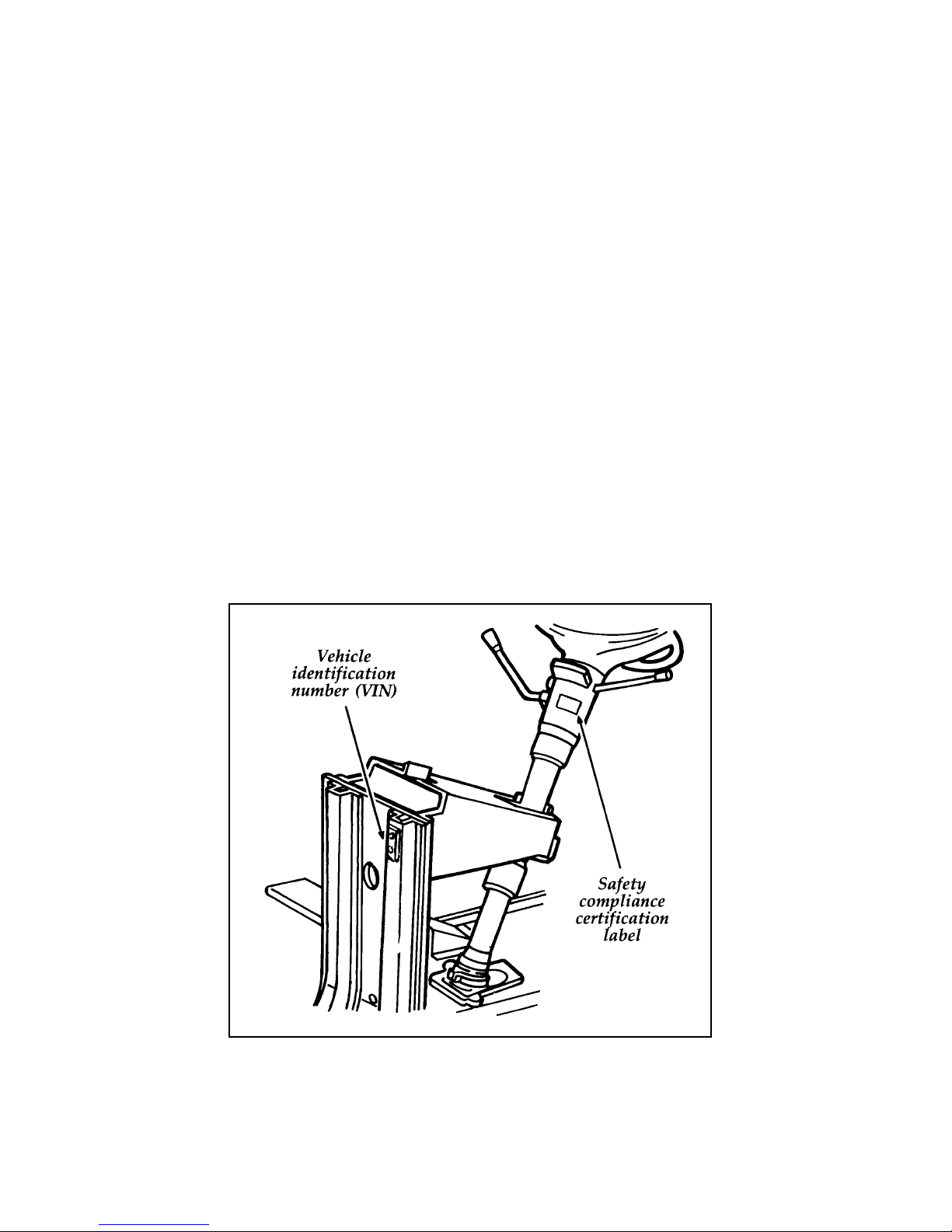
Number (VIN)
Your Vehicle Identification Number (VIN) is the
same as the warranty number that appears on
your owner card. You should include this
number any time you write to Ford Motor
Company about your vehicle.
5
Page 10

The Vehicle Identification (VIN) is stamped on a
metal tag attached to the chassis front end
structure. It is visible from outside the vehicle
under the hood.
Safety Compliance Certification Label
You’ll also find the VIN and other important
information on the Safety Compliance
Certification Label. It is required by the National
Highway Traffic Safety Administration and is
made of special material. If someone tampers
with it, it will be destroyed and/or a destruction
pattern will appear.
The label contains the name of the manufacturer,
the month and year of manufacture, the
certification statement and the Vehicle
Identification Number. The label also contains
Gross Vehicle Weight Rating and Gross Axle
Weight Ratings, wheel and tire data and
information codes for additional vehicle data.
For further information about the Safety
Compliance Certification Label and the
information contained on it, refer to the Index.
Incomplete Vehicles
On completed derivations of incomplete vehicles,
the Safety Compliance Certification Label is
affixed at a location determined by a subsequent
stage manufacturer of the completed vehicle. In
these cases the completed vehicle is
manufactured in two (or more) stages by two (or
more) separate manufacturers, with the
manufacture of the completed vehicle occurring
at a later date than the manufacture of the
incomplete vehicle. Consequently, the model
year of the completed vehicle may be later than
the model year of its chassis.
6
Page 11

Federal Highway Administration
Regulation
Regulations such as those issued by the Federal
Highway Administration or issued pursuant to
the Occupational Safety and Health Act (OSHA),
and/or state and local laws and regulations may
require additional equipment for the way you
intend to use the vehicle. It is the responsibility
of the registered owner to determine the
applicability of such laws and regulations to
your intended use for the vehicle, and to
arrange for the installation of required
equipment. Your Ford dealer has information
about the availability of many items of
equipment which may be ordered for your
vehicle.
Your new vehicle goes through an adjustment or
break-in period during the first 1,000 miles
(1,600 km) that you drive it. During the break-in
period, you need to pay careful attention to how
you drive your vehicle.
Avoid sudden stops. Because your vehicle
❑
has new brake linings, you should take these
steps:
— Watch traffic carefully so that you can
anticipate when to stop.
— Begin braking well in advance.
— Apply the brakes gradually.
The break-in period for new brake linings
lasts for 100 miles (160 km) of city driving or
1,000 miles (1,600 km) of highway driving.
7
Page 12

Wheel lug nuts must be retightened to proper
❑
torque specifications at 500 miles/800 km of
new vehicle operation. Proper torque
specifications are provided in this guide. Also
retighten to proper torque specification at 500
miles/800 km after any wheel change or any
other time the wheel lug nuts have been
loosened.
Use only the type of engine oil that Ford
❑
recommends. Don’t add anti-friction
compounds or special break-in oils during the
first few thousand miles of operation. These
additives may prevent piston ring seating.
8
Page 13
Starting Your Motorhome
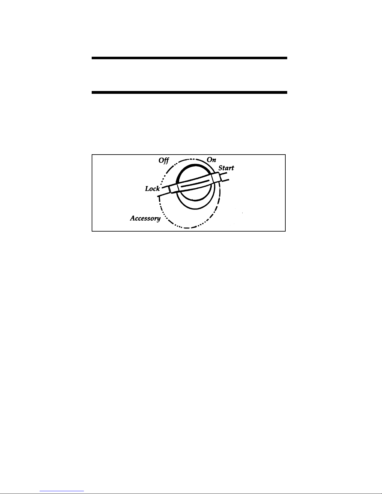
Understanding the Positions of the Ignition
The positions of the key in the ignition lock cylinder.
ON allows you to test your vehicle’s warning
lights (except the brake system warning light) to
make sure they work before you start the
engine. The key returns to the ON position once
the engine is started and remains in this position
while the engine runs.
START cranks the engine. Release the key once
the engine starts so that you do not damage the
starter. The key should return to ON when you
release it. The START position also allows you
to test the brake warning light.
OFF allows you to shut off the engine and all
accessories without locking the steering wheel or
the automatic transmission gearshift lever.
LOCK locks the steering wheel. It also locks the
gearshift.
9
Page 14

RWARNING
Always set the parking brake fully and
make sure that the gearshift is securely
latched in P (Park).
LOCK is the only position that allows you to
remove the key. The LOCK feature helps to
protect your vehicle from theft.
If the key is stuck in the LOCK position, move
the steering wheel left or right until the key
turns freely.
ACCESSORY allows some of your vehicle’s
electrical accessories such as the radio and the
windshield wipers to operate while the engine is
not running.
Removing the Key From the Ignition
Procedures for removing your key from the
ignition are as follows:
Your vehicle’s gearshift lever is mounted on
the column:
1. Put the gearshift in P (Park).
2. Set the parking brake fully before removing
your foot from the service brake. (This will
avoid “binding” or “loading” the park gear
if you park on a grade.)
3. Turn the ignition key to LOCK.
4. Remove the key.
10
Page 15
RWARNING
Always set the parking brake fully and
make sure that the gearshift is securely
latched in P (Park).
RWARNING
Do not leave children, unreliable adults,
or pets alone in your vehicle. They could
accidentally injure themselves or others
through inadvertent operation of the
vehicle. Further, on hot, sunny days,
temperatures in a closed vehicle could
quickly become high enough to cause
severe and possibly fatal injuries to
people as well as animals.
Climate conditions and other factors play a large
part in deciding how you should go about
starting your vehicle. Read all the starting
instructions carefully, so you’ll be aware of these
factors when you start your vehicle.
When starting a fuel-injected engine, the most
important thing to remember is to avoid
pressing down on the accelerator before or
during starting. See Starting Your Engine in this
chapter for details about when to use the
accelerator while you start your vehicle.
11
Page 16

Preparing to Start Your Vehicle
RWARNING
Do not start your vehicle in a closed
garage or other enclosed area. Never sit in
a stopped vehicle for more than a short
period of time with the engine running.
Exhaust fumes are toxic. See Guarding
Against Exhaust Fumes in this chapter for
more instructions.
Before you start your vehicle, do the following:
1. Make sure you and all your passengers
buckle your safety belts.
2. Make sure the headlamps and other
accessories are turned off when starting.
3. Make sure that the gearshift is in P (Park)
and the parking brake is set before you turn
the key.
Starting Your Engine
To start your engine:
1. Follow the steps under Preparing to Start
Your Vehicle at the beginning of this section.
2. Turn the ignition key to the ON position.
3. DO NOT depress the accelerator pedal when
starting your engine. DO NOT use the
accelerator while the vehicle is parked.
4. Turn the key to the START position
(cranking) until the engine starts. Allow the
key to return to the ON position after the
engine has started.
rotate the steering wheel slightly because it
may be binding.
12
Page 17

For a cold engine:
At temperatures 10˚F (-12˚C) and below: If
❑
the engine does not start in fifteen (15)
seconds on the first try, turn the key to OFF,
wait approximately ten (10) seconds so you
do not flood the engine, then try again.
At temperatures above 10˚F (-12˚C): If the
❑
engine does not start in five (5) seconds on
the first try, turn the key to OFF, wait
approximately ten (10) seconds so you do not
flood the engine, then try again.
Do not hold the key in the START position
❑
for more than fifteen (15) seconds at a time.
For a warm engine:
Do not hold the key in the START position
❑
for more than five (5) seconds at a time. If
the engine does not start within five (5)
seconds on the first try, turn the key to the
OFF position. Wait a few seconds after the
starter stops, then try again.
Whenever you start your vehicle, release the key
as soon as the engine starts. Excessive cranking
could damage the starter or flood the engine.
After you start the engine, let it idle for a few
seconds. Keep your foot on the brake pedal and
put the gearshift lever in gear. Release the
parking brake. Slowly release the brake pedal
and drive away in the normal manner.
13
Page 18

NOTE: Your vehicle is equipped with a
brake-shift interlock feature. This
feature prevents you from shifting
from P (Park) unless you have the
brake pedal depressed. (The ignition
must be in the ON position.) If you
cannot shift from P (Park) with the
brake pedal depressed:
1. Apply the parking brake.
2. Remove the key.
3. Insert the key and rotate one position
clockwise (ignition in the OFF position).
4. Apply the brake pedal and shift to N
(Neutral). (If the vehicle is shifted to P
(Park), you must repeat the previous steps.)
5. Start the vehicle.
If you need to shift out of P (Park) by using the
alternate procedure described above, it is
possible that a fuse has blown and that your
brakelamps may also not be functional. Please
refer to the chapter titled Servicing Your
Motorhome in this Owner Guide for instructions
on checking and replacing fuses.
RWARNING
DO NOT DRIVE YOUR VEHICLE UNTIL
YOU VERIFY THAT THE BRAKELAMPS
ARE WORKING.
For cold or warm engines:
If the engine still does not start after two
attempts:
1. Turn the ignition key to the OFF position.
2. Press the accelerator all the way to the floor
and hold it.
14
Page 19
3. Turn the ignition key to the START position.
4. Release the ignition key when the engine
starts.
5. Release the accelerator gradually as the
engine speeds up. Then drive away in the
normal manner.
If the engine still does not start, the fuel pump
shut-off switch may have been triggered. For
directions on how to reset the switch see Fuel
Pump Shut-Off Switch later in this chapter.
NOTE: When turning the ignition key from
the “OFF” to the “RUN” position, a
subtle humming may be heard for up
to three seconds. This is the normal
sound of an electronically controlled
fuel pump, and indicates the operation
or pre-pressurizing the EFI system for
starting.
If the engine idle speed does not slow down
automatically, do not allow your vehicle to idle
for more than 10 minutes. Have the vehicle
checked.
RWARNING
Extended idling at high engine speeds can
produce very high temperatures in the
engine and exhaust system, creating the
risk of fire or other damage.
RWARNING
Do not park, idle, or drive your vehicle in
dry grass or other dry ground cover. The
emission system heats up the engine
compartment and exhaust system, which
can start a fire.
15
Page 20
Not Start or Does Not Start After
a Collision
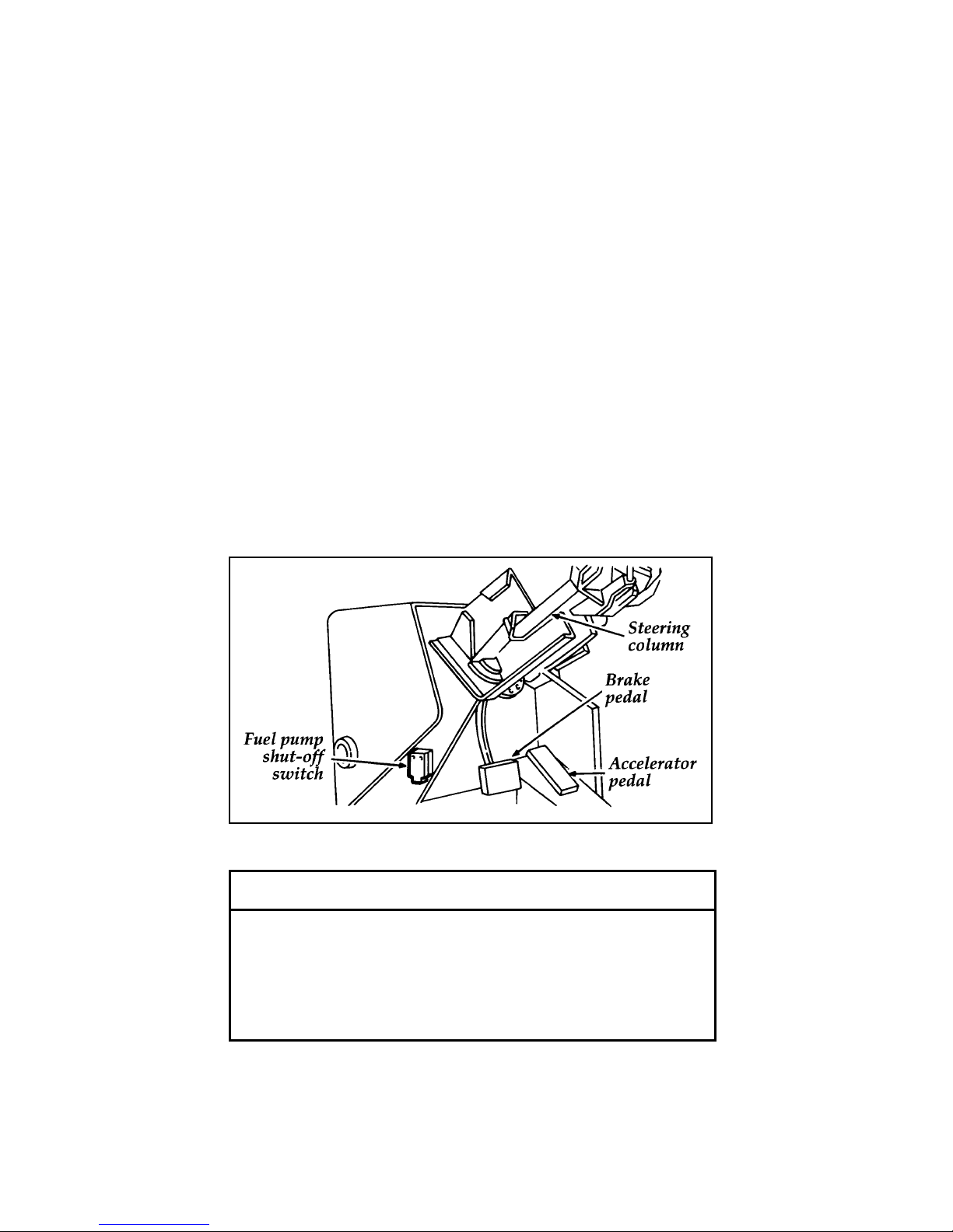
Fuel Pump Shut-off Switch
If the engine cranks but does not start or does
not start after a collision, the fuel pump shut-off
switch may have been triggered. The shut-off
switch is a device intended to stop the fuel
pump when your vehicle has been involved in a
substantial jolt.
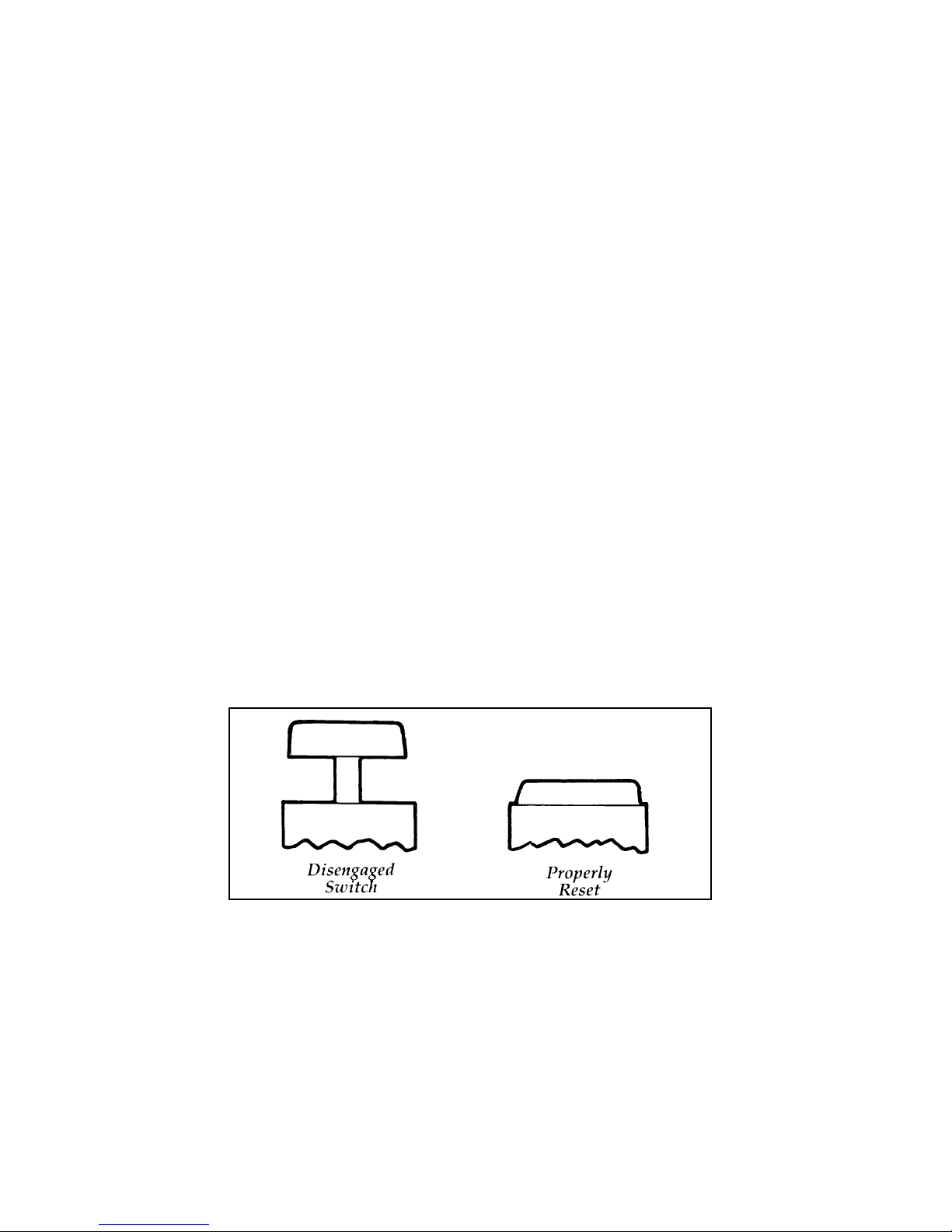
Once the shut-off switch is triggered, you must
reset the switch by hand before you can start
your vehicle.
Fuel pump shut-off switch location
If you see or smell fuel, do not reset the
switch or try to start your vehicle. Have
all the passengers get out of the vehicle
and call the local fire department or a
towing service.
16
RWARNING
Page 21
If your engine cranks but does not start after a
collision or substantial jolt:
1. Turn the ignition key to the OFF position.
2. Check under the vehicle for leaking fuel.
3. If you do not see or smell fuel, push the red
reset button down. If the button is already
set, you may have a different mechanical
problem.
4. Turn the ignition key to RUN for a few
seconds, then turn it OFF. (Do not start the
engine.)
5. Check under the vehicle again for leaking
fuel. If you see or smell fuel, do not start
your vehicle again. If you do not see or
smell fuel, you can try to start your vehicle
again.
6. Check all vehicle warning lights before
driving your vehicle.
Reset button for fuel pump shut-off switch
17
Page 22
Guarding Against Exhaust Fumes
Carbon monoxide, although colorless and
odorless, is present in exhaust fumes. Take
precautions to avoid its dangerous effects.
RWARNING
Do not start your vehicle in a closed
garage or other enclosed area. Never sit in
a stopped vehicle for more than a short
period of time with the engine running.
Exhaust fumes are toxic. See Guarding
Against Exhaust Fumes in this chapter for
more instructions.
RWARNING
If you smell exhaust fumes inside your
vehicle, have your dealer inspect your
vehicle immediately. Do not drive if you
smell exhaust fumes.
Have the exhaust and body ventilation systems
checked whenever:
your vehicle is raised for service
❑
the sound of the exhaust system changes
❑
your vehicle has been damaged in a collision
❑
Improve your ventilation by keeping all air inlet
vents clear of snow, leaves, and other debris.
If the engine is idling while you are stopped in
an open area for long periods of time, open the
windows at least one inch (2.5 cm). Also, adjust
the heating or air conditioning to bring in
outside air.
18
Page 23

HEATING — Set fan speed at MEDIUM or
❑
HIGH, the function selector knob on VENT,
FLOOR, FLR DEF or DEFROST symbol and
the temperature control knob on any desired
position.
AIR CONDITIONING — Set the fan speed at
❑
MEDIUM or HIGH, the function selector
lever on NORM or VENT and the
temperature control knob on any desired
position.
TAPPET NOISE
It is normal for the oil to drain down from the
hydraulic tappets in your engine during
extended shutdown periods (overnight). As a
result, these tappets may clatter for a few
seconds after the engine starts until oil pressure
builds up. This momentary start-up noise is
normal and is not harmful to engine operation.
19
Page 24

Notes
20
Page 25

Warning Lights and
Gauges
The instrument panel (dashboard) on your
vehicle is divided into several different sections.
The illustrations on the following pages show
the major parts of the instrument panel that are
described in this chapter. Some items shown
may not be on all vehicles.
In your vehicle, the warning lights and gauges
are grouped together on the instrument panel.
We call this grouping a cluster. Your vehicle has
a mechanical cluster.
21
Page 26

[LG02800( M)05/95]
full page art:0021215-B
File:ltlgm.ex
Update:Tue Jun 20 16:47:10 1995
Page 27
The following warning lights and gauges are on
the mechanical cluster. All of the warning lights
and gauges alert you to possible problems with
your vehicle. Some of the lights listed are
optional. The following sections detail what each
of these indicators means.
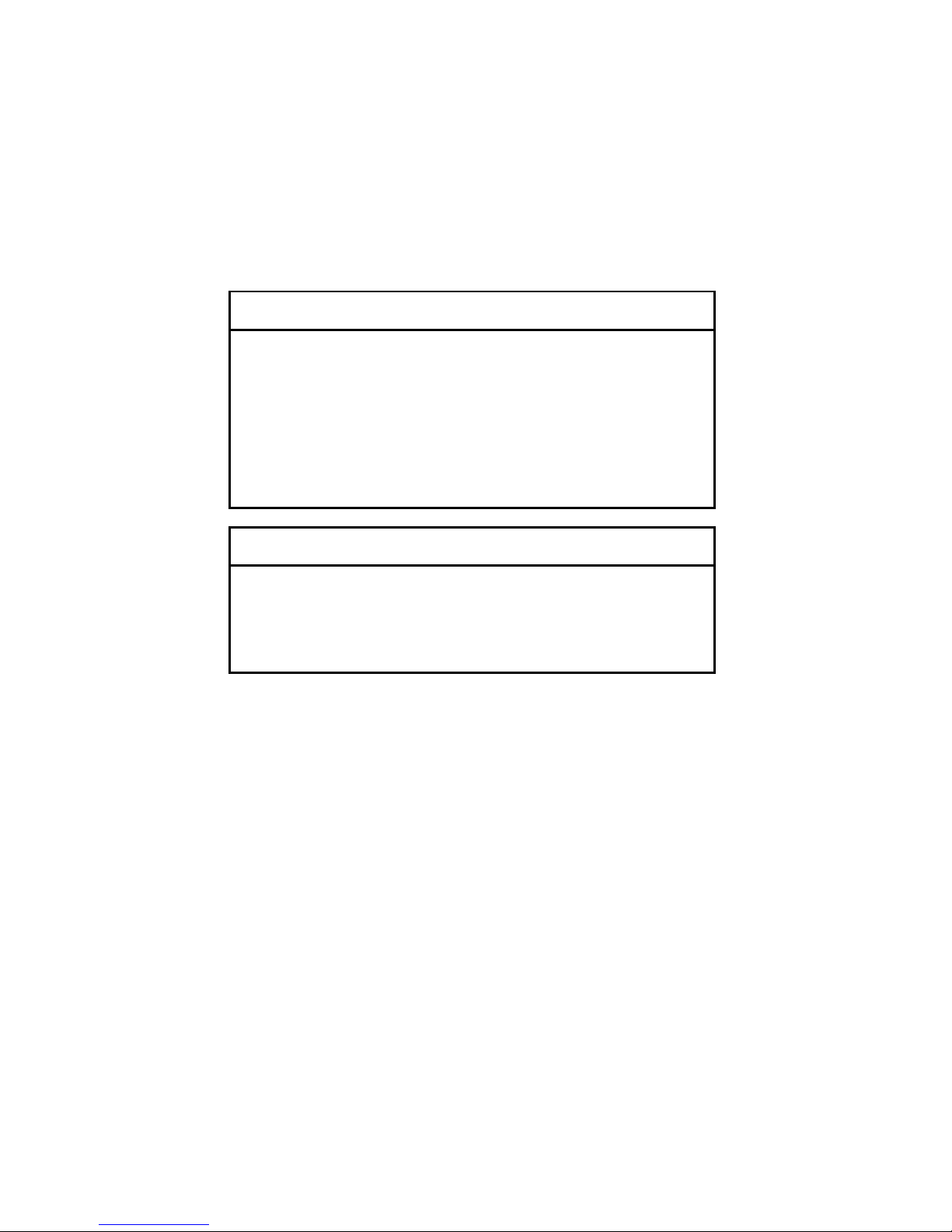
Brake System Warning Light
The warning light for the brakes can show two
things — that the parking brake is not fully
released, or that the brake fluid level is low in
the master cylinder reservoir. If the fluid level is
low, the brake system should be checked by
your dealer or a qualified service technician.
This light comes on when you turn the ignition
key to START to verify that the indicator bulb is
working. If the light stays on or comes on after
you have released the parking brake fully, have
the hydraulic brake system serviced.
RWARNING
The BRAKE light indicates that the brakes
may not be working properly. Have the
brakes checked immediately.
Brake warning light symbols
23
Page 28
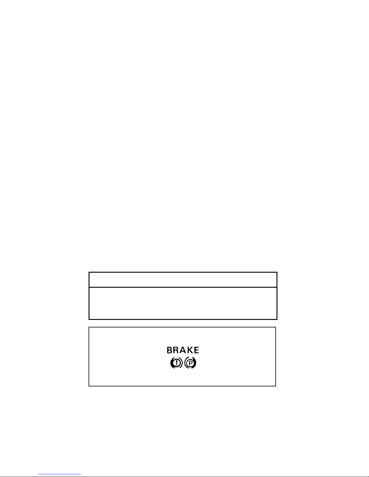
Safety Belt Warning Light
The warning light reminds you to fasten your
safety belt. Each time the ignition is turned to
ON, the warning light comes on for four to
eight seconds to remind you to fasten your
safety belt.
Safety belt warning light symbol
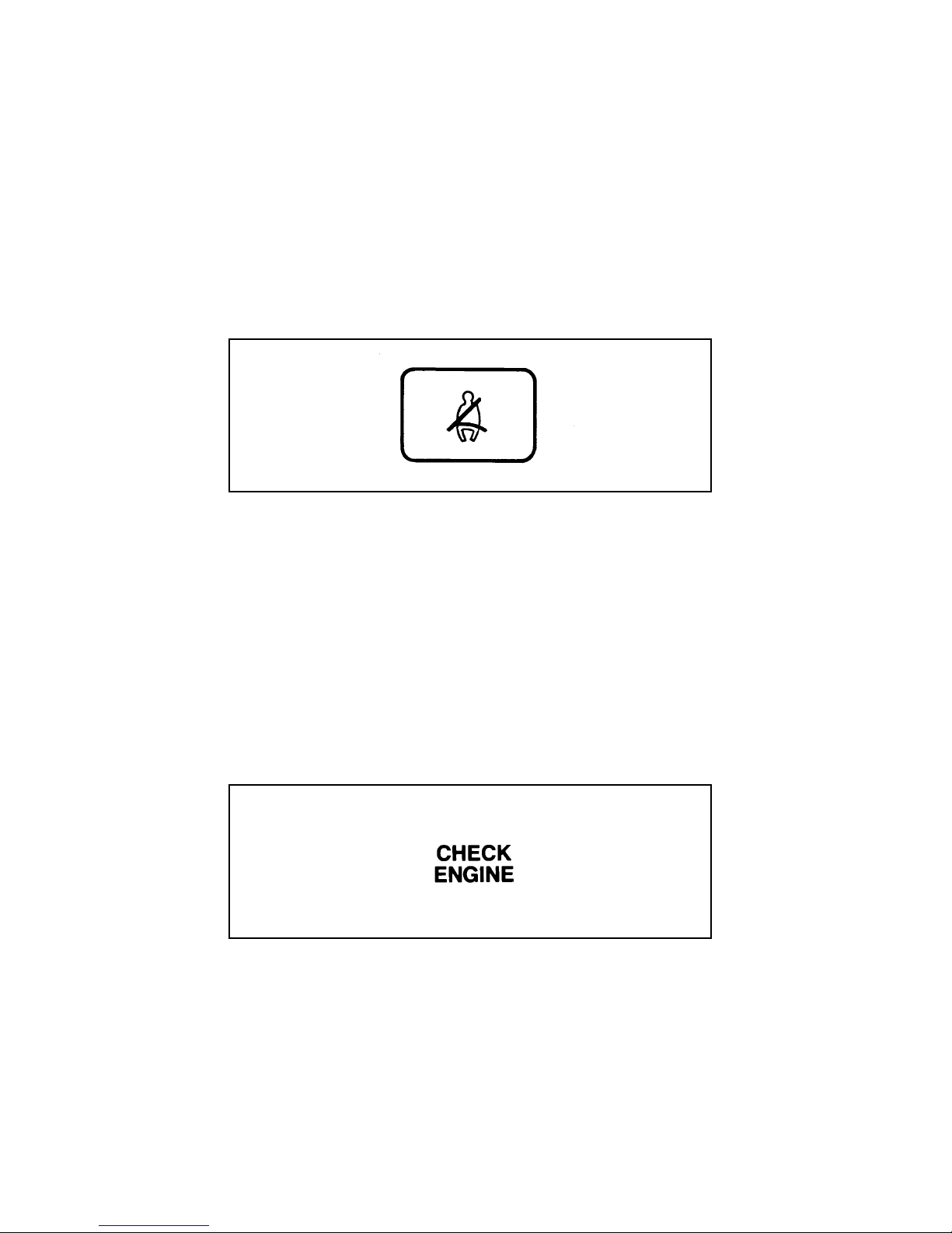
Check Engine Warning Light
The Powertrain On-Board Diagnostic II (OBD II)
system consists of the hardware and software
necessary to monitor the operation of the
powertrain. The OBD II system is designed to
check the function of the vehicle’s powertrain
control system during normal operation. If an
emission problem is detected, the Check Engine
Warning Light (in the cluster) is turned on.
Check engine warning light symbol
24
Page 29

Modification or additions to the vehicle may
cause incorrect operation of the OBD II system.
Additions such as burglar alarms, cellular
phones, and CB radios must be carefully
installed. Do not install these devices by tapping
into or running wires close to powertrain control
system wires or components.
The light comes on briefly when you turn the
ignition key to ON, but it should turn off when
the engine starts. If the light does not come on
when you turn the ignition to ON or if it comes
on and stays on when you are driving, have
your vehicle serviced as soon as possible. This
indicates a possible problem with one of the
vehicle’s emission control systems. You do not
need to have your vehicle towed in.
If the light turns on and off at one (1) second
intervals while you are driving the vehicle, it
means that the engine is misfiring. If this
condition persists, damage could occur to the
engine or catalytic convertor. Have your vehicle
serviced at the first opportunity. You do not
need to have your vehicle towed in.
If the light turns on and off on rare occasions
while you are driving, it means that a
malfunction occurred and the condition corrected
itself.
An example of a condition which corrects itself
occurs when an engine running out of fuel
begins to misfire. In this case, the Check Engine
Warning Light may turn on and will then set a
Diagnostic Trouble Code indicating that the
engine was misfiring while the last of the fuel
was being consumed. After refueling, the Check
Engine Warning Light will turn off after the
vehicle has completed three consecutive warm
up cycles without a misfire condition occurring.
A warm up cycle consists of engine start from a
25
Page 30

cold condition (engine at ambient temperature)
and running until the engine reaches normal
operating temperature.
On the fourth engine start up, the Check Engine
Warning Light will turn off as soon as the
engine begins to crank. It is not necessary to
have the engine serviced.
Under certain conditions, the Check Engine
Warning Light may come on if the fuel cap is
not properly installed. If the Check Engine
Warning Light comes on and you suspect that
the fuel cap is not properly installed, pull off the
road as soon as it is safely possible and turn off
the engine. Remove and replace the fuel cap,
making sure it is properly seated.
After completing the three consecutive warm up
cycles and on the fourth engine start up, the
Check Engine Warning Light should turn off. If
the light does not go off after the fourth engine
restart, have your vehicle serviced by your
dealer or a qualified technician.
Charging System Light
This light, shown as a battery symbol on your
cluster, indicates that your battery is not being
charged and that you need to have the electrical
system checked.
Charging system light
26
Page 31

This light comes on every time you turn the
ignition to the ON or START position (engine
off). The light should go off when the engine
starts and the alternator begins to charge.
If the light stays on or comes on when the
engine is running, have the electrical system
checked as soon as possible.
Battery Voltage Gauge (Voltmeter)
This gauge shows you the battery voltage when
the ignition key is in the ON position.
If you are running electrical accessories (when
the engine is off, or idling at a low speed), the
pointer may move toward the lower end of the
normal band. If it stays outside the normal band
area, have your vehicle’s electrical system
checked as soon as it is safely possible.
If the battery is operating under cold weather
conditions, the pointer may indicate in the upper
range of the NORMAL band while the battery is
charging. If you are running electrical accessories
with the engine off or idling at a low speed, or
the battery is not fully charged, the pointer may
move toward the lower end of the NORMAL
band.
If it stays outside the NORMAL band, have your
vehicle’s electrical system checked as soon as it
is safely possible.
Battery voltage gauge
27
Page 32

Engine Oil Pressure Gauge
This gauge indicates the engine’s oil pressure,
not the oil level. However, if your engine’s oil
level is low, it could affect the oil pressure. With
the engine running, the pointer should move
into the NORMAL band. If the pointer drops
below the NORMAL band while the engine is
running, you have lost oil pressure and
continued operation will cause severe engine
damage.
If you lose engine oil pressure:
1. Pull off the road as soon as safely possible.
2. Shut off the engine immediately or severe
engine damage could result.
3. Check the engine’s oil level, following the
instructions on checking and adding engine
oil. Refer to Engine oil in the Index. If you
do not follow these instructions, you or
others could be injured. To assure an
accurate reading, your vehicle should be on
level ground.
4. If the level is low, add only as much oil as
necessary before you start the engine again.
Do not overfill. Do not operate the engine if
the pointer is below the NORMAL band,
regardless of the oil level. Contact your
nearest dealer for further service actions.
Engine oil pressure gauge
28
Page 33

High Beam Light
This light comes on when the headlamps are
turned on high beam or when you flash the
lights.
High beam indicator light
Fuel Gauge
The fuel gauge displays approximately how
much fuel is in the fuel tank only when the
ignition switch is ON.
For a proper fuel gauge indication after adding
fuel, the ignition switch should be in the OFF
position while the vehicle is being refueled.
The fuel gauge indicator may vary slightly when
the vehicle is in motion.
With ignition switch OFF, the fuel gauge
indicator may drift from the ignition switch ON
position.
Fuel gauge
29
Page 34

Engine Coolant Temperature Gauge
This gauge tells you the temperature of the
engine coolant, not the coolant level. If the
coolant is not at its proper level or mixture, the
gauge indicator will not be accurate.
The pointer moves from the C (cold) mark into
the Normal band as the engine coolant warms
up. It is acceptable for the pointer to fluctuate
within the Normal band under normal driving
conditions. Under certain driving conditions,
such as heavy stop and go traffic or driving up
hills in hot weather, the pointer may indicate at
the top of the Normal band.
If, under any circumstances, the pointer moves
above the NORMAL band, the engine coolant is
overheating and continued operation may cause
engine damage.
If your engine coolant overheats:
1. Pull off the road as soon as it is safely
possible.
2. Turn off the engine. If you do not stop the
engine as soon as safely possible, severe
engine damage could result.
3. Let the engine cool. DO NOT REMOVE
COOLANT SYSTEM FILL CAP UNTIL
THE ENGINE IS COOL.
4. Check the coolant level following the
instructions on checking and adding coolant
to your engine, see Engine Coolant in the
Index. If you do not follow these
instructions, you or others could be injured.
For instructions on checking and adding coolant
to your engine, see Engine coolant in the Index. If
you do not follow these instructions, you or
others could be injured.
30
Page 35

Engine coolant temperature gauge
Speedometer
The speedometer tells you how many miles
(kilometers) per hour your vehicle is moving.
Your vehicle contains a speedometer which
receives its input from a speed sensor. The
speedometer is also used to provide a speed
signal for correct operation of the vehicle’s
Electronic Engine Control (EEC) module,
electronic transmission, and speed control
(if so equipped).
31
Page 36

Speedometer
Odometer/Trip Odometer
The Liquid Crystal Display (LCD) odometer is a
combination trip odometer and total odometer.
The total odometer is normally displayed. To see
the trip odometer, press and release the SELECT
BUTTON on the upper right side of the
speedometer. To zero out the trip odometer,
press and release the RESET button on the
upper left side of the speedometer while the trip
odometer is displayed. If the trip odometer is
displayed, press and release the “Select” button
to return the display to the total odometer value.
32
Page 37

Instrument Panel Controls
NOTE: The following section does not apply
to Stripped Chassis vehicles. See your
Body Builder’s instructions for location
and operation of controls for climate
control systems, lamps and radio.
Turning On the Exterior Lights
To turn on your headlamps, parking lamps,
marker lamps, and tail lamps, use the headlamp
switch to the left of the steering column.
1. Pull the headlamp control knob toward you
to the first position. Parking lamps, tail
lamps and marker lamps are now on.
2. Pull the headlamp control knob toward you
to the outer position. Headlamps are now on
in addition to the above.
33
Page 38

Headlamp switch
Daytime Running Light System
(Canadian vehicles only)
The Daytime Running Light (DRL) system turns
the high beam headlamps on, with a reduced
light output, when:
The headlamp system is in the OFF position,
❑
and
The vehicle is running, and
❑
The vehicle has a fully released parking
❑
brake.
NOTE: You may notice that the lights flicker
when the vehicle is turned on or off.
This is a normal condition.
34
Page 39

Steering Column Controls
The controls on the steering column and wheel
are designed to give you easy access to the
controls while you are driving.
You can use the turn signal lever on the left side
of the steering column to:
operate the turn signals and cornering lamps
❑
Turn Signals
Move the lever up to signal a right turn. Move
it down to signal a left turn. The corresponding
indicator light in the instrument cluster will
flash.
If the turn signal stays on after you turn, move
the lever back to the center (off) position.
Turn signal lever and functions
35
Page 40

If the turn indicator light in the instrument
panel does not illuminate or remains on (doesn’t
flash) when you signal a turn, the turn signaling
system is malfunctioning. Have this condition
corrected as soon as possible, but make sure that
you use the accepted hand signals in the
meantime.
High Beams
To turn on the high beams, turn the headlamp
control knob to the headlamp ON position and
push the turn signal lever away from you until
it latches. When the high beams are ON, the
high beam indicator light on the instrument
panel comes on.
To turn off the high beams, pull the lever
toward you until it latches. The high beam
indicator light turns off.
Headlamp high beam switch and turn signal lever
Flashing the Lights
To flash the headlamps, pull the lever toward
you for a moment and then release it. The
headlamps will flash whether the headlamp
knob is in the on or off position.
36
Page 41

To turn on the windshield wipers, the ignition
key must be turned to the ON or ACC position.
Turn the knob on the end of the turn signal
lever toward the front of the vehicle. You can
turn it to either the LO or HI speed position.
Variable Interval Wipers
In addition to two speed wipers, your vehicle is
equipped with wipers that you can set to
operate at varying intervals. For example, you
can set the interval so they wipe less often when
it drizzles or more often in heavier rain.
Interval wiper on turn signal lever
To set the interval wipers, rotate the knob at the
end of the turn signal lever toward or away
from the instrument panel to the interval
operation you desire.
Windshield Washer
To clean the windshield, push in the end of the
wiper knob. For a constant spray, keep the knob
pushed in. After you release the knob, the
wipers operate for two to three cycles before
turning off (if wipers were off) or returning to
the interval selected.
37
Page 42

Do not try to clean the windshield when the
washer fluid container is empty or activate the
washers at any time for more than 15 seconds
continuously. This could damage the washer
pump system.
RWARNING
In freezing weather, the washer solution
may freeze on the windshield and obscure
your vision. Always warm up the
windshield with the defroster before you
use the washer fluid. If you cannot see
through the windshield clearly, it can
increase the risk of being involved in a
collision.
The hazard flasher is used to alert other drivers
to hazardous situations.
The flashers will continue to flash with the brake
pedal depressed.
The flashers work whether your vehicle is
running or not. The flashers work for up to two
hours when the battery is fully charged and in
good condition without draining the battery
excessively. If the flashers run for longer than
two hours or if the battery is not fully charged,
the battery can be drained.
To use the hazard flasher:
1. Push in the flasher button; it will pop out
and the lamps will begin to flash.
2. To stop the flashers, push in the flasher
button again.
38
Page 43

NOTE: The flasher button will be sticking up
slightly higher when ON than when
OFF.
Hazard flasher
To sound the horn, push the center pad area of
the steering wheel.
Horn location
39
Page 44

RWARNING
Never adjust the steering wheel when the
vehicle is moving.
Turn signal and tilt release wheel lever
To change the position of the steering
column/wheel, pull the release lever on the
column toward you. Tip the steering wheel to
the desired position. Release the lever to lock the
steering wheel in place.
Be sure the steering wheel locks in a notch. It is
not infinitely adjustable. Do not adjust the
steering wheel while the vehicle is in motion.
Your vehicle has speed control, so you can
automatically maintain a constant speed above
30 mph (50 km/h). The switches to operate the
speed control are on the steering wheel.
Use of radio transmitting equipment that is not
Federal Communications Commission (FCC) or
in Canada the Canadian Radio and
Telecommunications Commission (CRTC)
40
Page 45

approved may cause the speed control to
malfunction. Therefore, use only properly
installed FCC (CRTC in Canada) approved radio
transmitting equipment in your vehicle.
The speed control switches
To set the speed control:
1. Press and release the ON switch.
2. Accelerate to the desired speed above
30 mph (50 km/h) using the accelerator
pedal.
3. Press the SET–ACCEL switch and release it
immediately to set your speed. If you keep
this switch pressed, your speed will continue
to increase.
4. Take your foot off the accelerator pedal.
Your vehicle will maintain the speed you set.
If you drive up or down a steep hill, your
vehicle may momentarily slow down or speed
up, even though the speed control is on. This is
normal.
41
Page 46

NOTE: If your speed increases above your set
speed while driving in j (Overdrive)
on a downhill grade, you may want to
depress the transmission control switch
located on the shift lever to turn off
overdrive to reduce vehicle speed.
Speed control cannot reduce the vehicle
speed if it goes above your set speed
on a downhill grade. For the best fuel
economy during normal driving
conditions, leave the shift select in j
(Overdrive), or resume as soon as
practical.
RWARNING
Do not use the speed control in heavy
traffic or on roads that are winding,
slippery, or unpaved.
In mountainous areas, at higher elevations, or
when pulling a trailer, the speed control may
not be able to maintain the preset speed with
the transmission in j (Overdrive).
RWARNING
Do not shift the transmission into N
(Neutral) with the speed control on.
To maintain a preset speed under the above
conditions, with electronically controlled
transmissions — press the Transmission Control
Switch. The indicator light will turn on and
illuminate the word “OFF.” This will cancel
“Overdrive”. You can press the Transmission
Control Switch on or off at any speed. For the
best fuel economy during normal driving
conditions, press the Transmission Control
Switch to turn off the light. This allows
overdrive operation.
42
Page 47

Transmission control switch and Indicator light
Accelerating With the Speed Control
Operating
You can use the accelerator pedal to speed up
momentarily. When you take your foot off the
accelerator, the vehicle will return to the set
speed.
Resetting the Speed Control
To reset the speed control to a lower speed,
press and hold the COAST switch. Let your
vehicle slow down to the desired speed and
release the COAST switch.
Your vehicle has a “tap-down” feature that
allows you to decrease your current speed in
increments of 1 mph (1.6 km/h) by a
momentary tap of the COAST switch. Multiple
taps of the COAST switch will decrease your
vehicle speed 1 mph (1.6 km/h) for each tap.
For example, if you are currently set at 65 mph
(104 km/h) and tap the COAST switch 5 times
your vehicle speed will decrease and set at
60 mph (96 km/h).
To reset the speed control to a higher speed,
you can follow any of these procedures:
Accelerate to the desired speed using the
❑
accelerator pedal, then press the SET–ACCEL
switch and release it immediately.
Press and hold the SET–ACCEL switch until
❑
the vehicle accelerates to the desired speed,
then release the switch.
43
Page 48

Turning the Speed Control Off
You can cancel the speed control while you are
driving.
Press the OFF switch. The speed control is
❑
off. If you want to resume speed control,
press the ON switch and reset the speed
control by pressing the SET ACCEL button.
Press the brake pedal slightly. The speed
❑
control is suspended, but you can reset it by
pressing SET ACCEL or return to the
previous set speed with the RESUME switch.
In addition, the speed control is turned off each
time you turn the vehicle off.
Driving uphill or on a steep grade
When the speed control is on, your vehicle may
significantly drop speed when driving uphill,
especially with a heavy load. If the speed drops
more than 8 to 14 mph (15 - 25 km/h) the
automatic speed control will, by design, be
canceled. You may have to temporarily resume
manual speed control while driving up a steep
grade in order to maintain the speed you desire.
Frequent shifting of an automatic transmission or
speed loss during speed control operation can be
eliminated by shifting out of overdrive into
drive (or by pressing the Transmission Control
Switch, if equipped). These conditions could
occur in hilly terrain or at higher elevations.
If the speed control “dropped out” after your
climb is completed, the speed of your vehicle
can be reset with the SET ACCEL switch, or
returned to the previous set speed with the
RESUME switch, as long as you are driving over
30 mph (50 km/h).
44
Page 49

Cancelling and Resuming a Set Speed
If you press the brake pedal, the speed control is
cancelled. You can return to the speed you set
by using the RSM switch, as long as you did not
press the OFF switch.
To resume the speed you had before, you must
be driving at least 30 mph (50 km/h).
Press and release the RESUME switch. Your
vehicle gradually returns to the previously set
speed and then maintains it.
RWARNING
If your vehicle has speed control, do not
use it on slippery roads. You could lose
control of your vehicle and could injure
someone.
45
Page 50

Notes
46
Page 51

Driving Your Motorhome
Operation (E4OD)
The E4OD transmission is an electronically
controlled four speed automatic transmission
with overdrive. Transmission operation is
controlled by the Powertrain Control Module
(PCM).
The PCM will automatically adjust transmission
operation to make up for varying conditions.
Several sensors located on the engine and
transmission such as Throttle Position, Engine
Speed, Vehicle Speed and Transmission
Temperature are used by the PCM to shift the
transmission into a higher or lower gear when
required for the best performance and fuel
economy. For example, you may notice that the
transmission will upshift to a higher gear more
quickly when the vehicle is first driven and has
not reached normal operating temperature.
The PCM also controls the transmission’s Torque
Converter Clutch to further raise vehicle
performance and fuel economy. The Torque
Converter Clutch will engage when the
transmission operating temperature and other
conditions determined by the PCM have been
met. Engagement of the clutch may be noted as
a decrease in engine speed after an upshift has
completed or when the driver has depressed the
throttle while driving at a steady road speed.
47
Page 52

To help in troubleshooting, the PCM continually
performs self-tests on the electronic control
system and if any faults are detected, will store
them in memory. The Transmission Control
Indicator Light (TCIL), which is located on the
gearshift lever, may flash steadily if a
malfunction has been detected. If the TCIL is
flashing, contact your Ford dealer as soon as
possible. If this condition persists, damage to the
transmission could occur.
NOTE: The word “OFF” located on the end of
the gearshift lever is the transmission
control indicator light (TCIL).
Putting Your Vehicle in Gear
Your vehicle’s gearshift is on the steering
column. The Transmission Control Switch and
indicator light are located on the end of the
gearshift lever. You can put the gearshift in any
of the several positions.
The positions of the column-mounted gearshift
48
Page 53

Transmission Control Switch and indicator light (located
on the gearshift lever)
RWARNING
Hold the brake pedal down while you
move the gearshift lever from position to
position. If you do not hold the brake
pedal down, your vehicle may move
unexpectedly and injure someone.
Once you place the gearshift securely into
position, gradually release the brake pedal and
use the accelerator as necessary.
NOTE: Your vehicle is equipped with a
brake-shift interlock feature. This
feature prevents you from shifting
from P (Park) unless you have the
brake pedal depressed. (The ignition
must be in the ON position.) If you
cannot shift from P (Park) with the
brake pedal depressed:
1. Apply the parking brake.
2. Remove the key.
3. Insert the key and rotate one position
clockwise (ignition in the OFF position).
4. Apply the brake pedal and shift to N
(Neutral). (If the vehicle is shifted to P
(Park), you must repeat the previous steps.)
5. Start the vehicle.
49
Page 54

If you need to shift out of P (Park) by using the
alternate procedure described above, it is
possible that a fuse has blown and that your
brakelamps may also not be functional. Please
refer to the chapter titled Servicing Your
Motorhome in this Owner Guide for instructions
on checking and replacing fuses.
RWARNING
DO NOT DRIVE YOUR VEHICLE UNTIL
YOU VERIFY THAT THE BRAKELAMPS
ARE WORKING.
R (Reverse)
With the gearshift in the R (Reverse) position,
the vehicle will move backward. You should
always come to a complete stop before shifting
into or out of R (Reverse).
Driving
When to use j (Overdrive)
This is the normal driving position. As the
vehicle picks up speed, automatic upshifts to
second, third and fourth gears will occur when
j Overdrive is chosen on the selector and the
transmission control switch has not been
pressed. The transmission will shift into the
correct gear when the right speed is achieved,
for the accelerator pedal position you have
chosen.
When to use Drive
You will note that there isn’t a drive position on
your gearshift indicator. However, you will find
a Transmission Control Switch and an indicator
light labeled “Overdrive” located on the end of
the gearshift lever. Press this switch and the
word “OFF” will illuminate on the shift lever
knob. With the word “OFF” illuminated, the
50
Page 55

transmission will operate in gears one through
three. Operating in the Overdrive “OFF” mode
gives more engine braking than Overdrive and
is useful for descending hills or when towing.
Transmission Control Switch and indicator light (located
on the gearshift lever)
To return the transmission to the normal j
Overdrive operation, press the transmission
control switch again. The Transmission Control
Indicator Light will not be illuminated when
Overdrive operation resumes. This switch may
be used to select O/D ON or O/D OFF any
time the vehicle is being driven.
When starting your vehicle, the overdrive system
will automatically be in the normal overdrive
mode.
If the Transmission Control Indicator Light is
flashing on and off steadily, a transmission
system malfunction was detected. The
transmission will operate in a failure
management mode and may have harsh
engagements, firm shift feel, or abnormal shift
schedule. If this condition persists, damage to
the transmission could occur. Contact your
dealer as soon as possible.
51
Page 56

When to use 2 (Second)
Use 2 (Second) to start-up on slippery roads or
to provide additional engine braking on
downgrades. This position provides 2 (Second)
gear operation only.
When to use 1 (Low)
Use 1 (Low) to provide maximum engine
braking on steep downgrades. Upshifts from 1
(Low) can be made by manually shifting to 2
(Second) or j (Overdrive). Selection of 1 (Low)
gear provides only low gear operation from
start-up. Selection of 1 (Low) while at higher
speeds provides a shift to second gear, and a
shift to first gear will occur after the vehicle
decelerates to the proper speed.
P (Park)
Always come to a complete stop before you shift
into P (Park). This position locks the
transmission and prevents the rear wheels from
turning. To securely latch the gearshift in the P
(Park) position, pull it toward you, push it
completely counterclockwise against the stop,
and then push it toward the instrument panel.
The gearshift is securely latched in P (Park) if
you cannot rotate it in a clockwise direction
without lifting it toward you.
RWARNING
Always set the parking brake fully and
make sure that the gearshift is securely
latched in P (Park).
RWARNING
Never leave your vehicle unattended
while it is running.
52
Page 57

Forced Downshifts
To gain extra acceleration in j Overdrive or
Drive (O/D OFF), push the accelerator to the
floor. The transmission will automatically
downshift to the appropriate gear: third, second
or first.
Power Braking
Increasing the engine speed above idle without
vehicle movement (such as holding the brake) in
a forward or reverse gear causes transmission
stall.
NOTE: Continued operation in the stall
condition can result in transmission
overheat, malfunction or fluid
expulsion.
Your vehicle comes with power steering. Power
steering uses energy from the engine to help
steer your vehicle.
If the amount of effort needed to steer your
vehicle changes at a constant vehicle speed, have
the power steering system checked. If the power
steering system breaks down (or if the engine is
turned off), you can steer the vehicle manually
but it takes more effort.
Never hold the steering wheel to the extreme
right or left for more than five seconds if the
engine is running. This can damage the power
steering pump.
53
Page 58

NOTE: After any severe impact such as
striking large potholes, sliding into
curbs on icy roads, or a collision
involving the front end, observe the
steering wheel alignment. If the spokes
of the steering wheel seem to be in a
different position while going straight
down the road, have the front
suspension and steering checked for
possible damage.
Your vehicle is equipped with the following
features:
Front self-adjusting disc brakes.
❑
Rear self-adjusting disc brakes.
❑
Independent front and rear hydraulic brake
❑
circuits with a common fluid reservoir and
fluid level sensor in the master cylinder.
Hydro boost.
❑
Parking brake.
❑
Front Disc Brakes
The front disc brakes are self-adjusting. They do
not require service other than periodic
lubrication of caliper slide rails and inspection
for pad wear.
Rear Disc Brakes
The rear disc brakes are self-adjusting. They do
not require service other than periodic
lubrication of the caliper slide rails and
inspection for pad wear.
54
Page 59

Hydraulic Power Brakes
The hydraulic brake system is made up of two
independent hydraulic circuits. One hydraulic
circuit supplies fluid to the front disc brakes and
the other hydraulic circuit supplies fluid to the
rear disc brakes. These two circuits are supplied
by a common hydraulic brake fluid reservoir,
with a fluid level sensor.
The brake light in the instrument cluster will
light for low brake fluid in the common brake
fluid reservoir.
RWARNING
An increase in pedal travel will result in
reduced braking capability. The brake
system should be checked immediately.
Hydraulic Brake Booster System
(Hydro Boost)
The Hydro Boost system receives its source of
power from the power steering system pump.
If Brakes Do Not Grip Well or Pedal is
“Low”
If during normal operation the brake pedal
seems “low”, it may indicate the need for a
brake system inspection and/or service. You
should have your brakes checked as soon as
possible.
Occasional brake squeal during light to moderate
stops does not affect the function of the brake
system and is normal. However, if the squeal
becomes annoyingly loud or increases
significantly in frequency of occurrence, return
the vehicle to your dealer for inspection.
55
Page 60

Stopping Distances
Stopping distances vary with different loads and
driving conditions. Use caution when
encountering new conditions and acquaint
yourself with vehicle performance. Take full
advantage of engine braking power when
slowing down.
Applying the Brakes
Apply the brake pedal gradually. Use the
“squeeze” technique — push on the brake pedal
with a steadily increasing force. This allows the
wheels to continue to roll while you are slowing
down, which lets you steer properly.
RWARNING
Do not drive with your foot resting on the
brake pedal. This will increase your
vehicle’s stopping distance and may also
cause brake damage.
RWARNING
If you are driving down a long or steep
hill, shift to a lower gear. Do not apply
your brakes continuously, as they may
overheat and become less effective.
When front or rear brake linings are replaced, it
is essential that authorized Ford service
replacement or equivalent linings be installed.
This will assure that the vehicle stopping
distances are not adversely affected and will
maintain the proper balance between front and
rear wheel braking.
56
Page 61

The parking brake pedal is suspended just below
the bottom of the instrument panel to the left of
the service brake. To set the parking brake while
parking your vehicle, press the brake pedal with
your right foot and hold it while you push the
parking brake pedal down firmly with your left
foot.
The BRAKE warning light will go on as soon as
you start to move the parking brake pedal. The
brake will not prevent the vehicle from moving
unless you push it down firmly and fully.
Remove your foot from the service brake pedal
and make sure there is no vehicle movement.
Parking Brake
Always set the parking brake fully and
make sure the gearshift is latched in P
(Park). Turn off the ignition whenever you
leave your vehicle.
To release the parking brake, press the service
brake pedal with your right foot and pull the
parking brake release lever.
RWARNING
57
Page 62

RWARNING
If the parking brake is fully released, but
the Brake System light remains on, have
the brakes checked immediately. They
may not be working properly.
The parking brake is not designed to stop a
moving vehicle, but you can use the parking
brake to stop your vehicle in an emergency if
the normal brakes fail. However, since the
parking brake applies only the transmission
mounted parking brake assembly, the stopping
distance will increase greatly and the handling
of your vehicle will be adversely affected.
Checking Parking Brake and Transmission
Park Mechanism
Periodically check the holding ability of the
parking brake by stopping on a steep hill and
restraining the vehicle by using only the parking
brake with the transmission in N (Neutral).
Check the holding ability of the P (Park)
mechanism (automatic transmissions) by
releasing all brakes after moving the
transmission selector lever to the P (Park)
position.
58
Page 63

Tips for Safe Driving
As with any new vehicle, yours may drive and
handle differently from your previous vehicle.
Use care until you become accustomed to its
various features and driving characteristics.
Operate your vehicle within reasonable limits.
Sudden acceleration, deceleration, turning, or
combinations of these maneuvers can cause a
vehicle to behave differently than anticipated.
Wheel Spin
Extreme acceleration can cause the rear
❑
wheels to spin, perhaps resulting in reduced
steering control.
If the wheels spin during vehicle start-up, shift
to a different gear:
Electronic 4-Speed Automatic Transmission
❑
E4OD: use 2 (Second)
Move forward slowly and evenly. If this does
not work, try rocking the vehicle.
High Speed Driving
Ford Motor Company recommends obeying
posted speed limits.
RWARNING
Driving too fast for conditions creates the
possibility of loss of vehicle control.
Driving at very high speeds for extended
periods of time may result in damage to
vehicle components.
59
Page 64

Driving in Bad Weather
Slippery roads
Drive cautiously on wet or snowy roads:
Do not quickly move the steering wheel
❑
unless necessary.
Drive slower than you normally would.
❑
Give your vehicle more distance to stop.
❑
Pump the brake pedal steadily and evenly to
❑
avoid locking your front wheels
To stop on ice, shift to N (Neutral) below 10
❑
mph (16 km/h) and gently pump brakes.
Consider using one of the lower gears.
❑
RWARNING
To avoid skidding and losing control on
slippery roads, do not downshift into First
(1) when you are moving faster than
20 mph (32 km/h).
High water
Never attempt to cross water that is fast flowing
or of unknown depth.
Do not drive through flooded areas unless you
are sure that the water is below the bottom of
the wheel hubs.
If you must drive through high water, drive
slowly. You may have limited traction or wet
brakes, so allow extra stopping distance because
your vehicle will not stop as quickly as usual.
60
Page 65

After you drive through the standing water,
apply your brakes gently several times as your
vehicle moves slowly. This helps to dry the
brakes.
NOTE: If the transmission is submerged in
water, the fluid should be checked and
changed, if necessary.
NOTE: All rear axle lube quantities must be
replaced every 100,000 miles
(160,000 km) or if the axle has been
submerged in water. Otherwise, the
lube should not be checked or changed
unless a leak is suspected or repair
required.
Rocking the vehicle
If your vehicle gets stuck (for example, in mud
or snow), you may rock it out of the spot. Shift
in a steady rhythm between forward and reverse
gears. Allow the transmission to fully engage,
then press lightly on the accelerator. Do not rock
the vehicle for more than a few minutes. This
may overheat the engine and transmission,
causing damage to both. In addition, other
vehicle systems and components may also be
damaged.
Do not spin the wheels at over 35 mph
(55 km/h). The tires may fail and injure a
passenger or bystander.
RWARNING
61
Page 66

Vehicle/Trailer Loads
All vehicles may tow a Class I trailer provided
the Gross Combined Weight (GCW) is less than
or equal to the GVWR shown on the Safety
Compliance Certification Label. For heavier
trailer applications, refer to the towing
information found later in this chapter.
Towing a trailer puts additional loads on your
vehicle’s engine, transmission, axle, brakes, tires
and suspension. For your safety and for the
good of your vehicle, use the right equipment
for the type of trailer you tow.
Your trailer towing capability will vary based on
the standard and optional equipment on your
vehicle. Refer to the following Vehicle
Loading/Towing Information and the Trailer
Towing Tables to determine the specific towing
capability of your vehicle.
Stay within the load limits when you tow.
❑
Carefully and thoroughly prepare your
❑
vehicle for towing, making sure to use the
right equipment and to attach it properly.
(See Preparing to Tow in this chapter.)
Use extra caution when driving your vehicle
❑
while you tow. (See Driving while you tow in
this chapter.)
Service your vehicle more frequently if you
❑
tow a trailer. (See Servicing your vehicle if you
tow in this chapter.)
Do not tow a trailer until your vehicle has been
driven at least 500 miles (800 km).
62
Page 67

Information
Your vehicle’s load capacity is designed by
weight, not volume, so you cannot necessarily
use all available space with large or heavy loads.
Maximum safe vehicle weights as well as tire,
rim sizes and inflation pressures are specified for
your vehicle on the Safety Compliance
Certification Label. A Safety Compliance
Certification Label was supplied by Ford Motor
Company to the Motorhome Manufacturer. The
manufacturer uses this information and supplies
a Compliance Certification Label which is
located inside the vehicle to the left of the
driver.
Trucks, unlike passenger cars, are basically
custom vehicles designed to carry a load. Most
owners start with a base vehicle and add
production and dealer installed and/or
aftermarket components to suit their tastes and
purposes. Even trucks that are purchased for
personal transportation only are likely to have
considerable optional equipment, such as step
bumpers and light bars, for example.
Passengers should not be allowed to ride
in the cargo area. Persons not riding in a
seat with a fastened seat belt are much
more likely to suffer serious injury in a
collision. Cargo should always be secured
to prevent it from shifting and causing
damage to the vehicle or harm to
passengers.
RWARNING
63
Page 68

Each additional item of equipment affects how
much cargo a vehicle can carry. If a vehicle is
overloaded, performance will suffer and service
concerns may arise.
Understanding Loading/Towing
Information
The following terms are used to describe the
ability to carry or tow a load:
Base Curb Weight
❑
Payload
❑
GVW (Gross Vehicle Weight)
❑
GVWR (Gross Vehicle Weight Rating)
❑
GAWR (Gross Axle Weight Rating)
❑
GCWR (Gross Combined Weight Rating)
❑
Maximum Trailer Weight Rating
❑
Maximum Trailer Weight
❑
Trailer Weight Range
❑
Base Curb Weight
The Base Curb Weight is the weight of the
vehicle including fuel, coolants, lubricants,
emergency tools, spare wheel and tire. It also
includes any equipment that is standard on that
model. It does not include passengers, cargo or
optional equipment installed by factory, dealer,
aftermarket supplier or customer.
Payload
Payload is the combined, maximum allowable
weight of cargo, occupants and optional
equipment that the truck is designed to carry. It
is Gross Vehicle Weight Rating minus the base
curb weight.
64
Page 69

Gross Vehicle Weight (GVW)
If you add base curb weight and the weight of a
load (including passengers, cargo and optional
equipment) being carried at a particular time,
you get the Gross Vehicle Weight (GVW).
It is important to remember that GVW is not a
limit or a specification. If an owner loads up a
vehicle and weighs it, that’s the GVW at that
moment. If the owner piles on more of a load
and weighs it again, that becomes the GVW
until such time as the vehicle is unloaded.
Gross Vehicle Weight Rating (GVWR)
To avoid overloading a vehicle, the owner
should observe the manufacturer’s specified
Gross Vehicle Weight Rating. The GVWR is the
maximum total weight of base vehicle,
passengers, optional components and cargo that
a particular vehicle was designed to carry.
Gross Axle Weight Rating (GAWR)
We have all seen a car or a truck that is loaded
down in the rear and riding high in the front.
This is a dangerous condition that usually means
that the rear suspension components are under
severe strain and that vehicle handling is
impaired. There is more to carrying a load than
just payload or GVWR.
Your Safety Compliance Certification Label not
only gives the GVWR, it also gives the Gross
Axle Weight Rating (GAWR) which is the
carrying capacity for each axle system. For
trucks, the rear axle will be designed to carry
more weight than the front.
65
Page 70

The rating is based on the carrying capacity of
the lowest rated axle and suspension component
as well as other factors. This is why it’s so
important to observe vehicle loading ratings.
Overloading a vehicle punishes components and
can lead to shortened service life or outright
failure.
The capacity of the tires is included as part of
the axle and suspension system, which is to be
considered when determining the lowest rated
component. Tires are rated to carry a specific
maximum load at a specific maximum tire
pressure.
Passenger car type tires when installed on light
trucks and multipurpose passenger vehicles are
rated at 10% lower load carrying capacity due to
the differences in vehicle usages.
With the tires inflated to the specified pressure
the total weight of your vehicle must not exceed
the GVWR and GAWR specified on the Safety
Compliance Certification Label. This includes full
fuel tank(s), vehicle equipment, and occupants as
well as the cargo load.
GCWR (Gross Combined Weight Rating)
GCWR is the maximum combined weight of the
towing vehicle (including passengers and cargo)
and the loaded trailer. The GCWR is specified
by the manufacturer to indicate the combined
maximum loaded weight that the vehicle is
designed to tow.
66
Page 71

Maximum Trailer Weight Rating
The maximum trailer weight rating is the
maximum weight of a trailer the vehicle is
permitted to tow. It is specified by the
manufacturer and is determined by subtracting
the vehicle curb weight for each
engine/transmission combination, any required
option weight for trailer towing and the weight
of the driver from the GCWR for the towing
vehicle.
Maximum Trailer Weight
The maximum trailer weight is the maximum
weight of a trailer the loaded vehicle is
permitted to tow. It is determined by subtracting
the weight of the loaded towing
vehicle (including passengers and cargo) from
the GCWR for the towing vehicle.
Trailer Weight Range
The trailer weight range is a specified range by
weight, which the trailer must fall within,
ranging from zero to the maximum trailer
weight rating.
Calculating The Load
To know how much weight your vehicle can
carry:
Obtain ratings from your Safety Compliance
❑
Certification Label, and the Trailer towing
specifications in the owner guide (refer to the
Index)
— Refer to the following sample illustration
to locate the various ratings on your
Safety Compliance Certification Label.
— If you do not plan on pulling a trailer, do
not include these ratings into your
calculations.
67
Page 72

Weigh your vehicle as you customarily
❑
operate the vehicle without cargo.
Subtract the total weight of passengers, driver
❑
and optional equipment added by the factory,
dealer or aftermarket supplier to determine
how much cargo weight you can carry.
Sample label
If you suspect that your payload is excessive,
have your vehicle weighed at a highway weigh
station or appropriate commercial facility. Weigh
the total vehicle and trailer (if applicable), then
separately weigh the vehicle at the front and
rear wheels. And finally, weigh the trailer
separately if applicable.
68
Page 73

Use this chart to perform your calculations.
NOTE: The Truck Safety Compliance
Certification Label has two weight
related entries that sometimes cause
confusion.
69
Page 74

Front Axle Reserve Capacity in Pounds (kgs): On
the sample label, this value is given as 83
pounds (38 kgs). Does this mean that you are
limited to adding only 83 pounds (38 kgs) of
accessories to the front end capacity? Not
exactly. This says that you can load 83 pounds
(38 kgs) of options on the front axle, add 150
pound (68 kgs) passengers to all seating
positions, and add evenly distributed cargo in
the box without exceeding the GAWR F.
It is possible to hang heavier equipment on the
front as long as the vehicle owner/operator
compensates. This can be accomplished, if
necessary, by carrying fewer passengers, less
cargo or positioning cargo more toward the rear,
which has the effect of reducing the load on the
front. Keep in mind that the GAWR F, GAWR
R, nor the GVWR should ever be exceeded.
Total Accessory Reserve Capacity in Pounds
(kgs): On the sample label this value is given as
112 pounds (51 kgs). This is a number that is
related to government crash test standards, and
only indirectly reflects on the amount of
accessory weight that can be carried.
In the case of both these numbers (83 and 112
pounds) (38 and 51 kgs), the important thing to
remember is that for safe operation, an
owner/operator should calculate the amount and
the distribution of all weights (passengers,
accessory equipment and cargo). These combined
weights should fall below the vehicle’s GVWR
and GAWR.
70
Page 75

Trailers
Towing a trailer safely means having the proper
weight on the tongue (usually 10% of the trailer
weight). Load-equalizing hitches on large rigs
may transfer weight to each of the vehicle’s
axles. This weight must be included in capacity
calculations when determining if the vehicle is
loaded within safe limits.
If your vehicle exceeds the GVWR, remove cargo
from your vehicle accordingly. If your vehicle
exceeds the GAWR for either axle, shift the load
or remove cargo accordingly.
RWARNING
If the GVWR or the GAWR specified on
the Safety Compliance Certification Label
is exceeded, your vehicle may be damaged
or you may lose control and injure
someone.
RWARNING
Towing trailers beyond the maximum
recommended gross trailer weight could
result in engine damage, transmission/axle
damage, structural damage, loss of control,
and personal injury.
Use the Safety Compliance Certification Label to
find the axle code number and the engine type
for your vehicle.
Use the appropriate Maximum Gross Combined
Weight Rating (GCWR) chart to find the
Maximum GCWR for your type engine and rear
axle ratio.
71
Page 76

Subtract your Loaded Vehicle Weight from the
Maximum GCWR found in the chart. This is the
maximum trailer weight your vehicle can tow
and must fall below the maximum shown under
Trailer Weight on the chart.
72
Page 77

Automatic Transmissions
Preparing to Tow
For your safety and for the good of your
vehicle, use the right equipment for the type of
trailer you tow. Also, make sure that all towing
equipment is properly attached to your vehicle.
If you are not certain that you are using the
right equipment in the proper manner, see your
Ford or Lincoln-Mercury dealer.
Hitches
For towing trailers up to 2,000 lb (907 kg), use a
weight carrying hitch and ball which uniformly
distributes the trailer tongue loads through the
underbody structure. Use a frame-mounted
weight distributing hitch for trailers over
2,000 lb (907 kg).
73
Page 78

Do not use single clamp bumper hitches or
hitches which attach to the axle. Provisions for
multi-clamp type temporary bumper hitch have
been provided (Class I, max. loading), if installed
properly. Follow towing instructions of a
reputable rental agency.
Whenever a trailer hitch and hardware are
removed, make sure all mounting holes in the
underbody are properly sealed to prevent
noxious gases or water from entering.
Safety Chains
Always use safety chains between your vehicle
and trailer. Cross chains under the trailer tongue
and allow slack for turning corners. Connect
safety chains to the vehicle frame or hook
retainers. Never attach chains to the bumper.
Trailer Brakes
Separate trailer brakes are required on most
towed vehicles weighing over 1,500 lb (680 kg).
RWARNING
Do not connect a trailer’s hydraulic brake
system directly to your vehicle’s brake
system. Your vehicle may not have
enough braking power and your chances
of having a collision greatly increase.
74
Page 79

Trailer lamps
Make sure your trailer lamps conform to Federal
and local regulations.
NOTE: Do not connect a trailer lighting system
directly to the lighting system of the
vehicle. See your local recreational
vehicle dealer or rental trailer agency
for correct type of wiring and relays
for your trailer and heavy-duty
flashers. Incorrect installation may
result in either a false warning or no
warning in the lamp outage warning
system.
RWARNING
Always replace a fuse with one that has
the specified amperage rating. Using a
fuse with a higher amperage rating can
cause severe wire damage and could start
a fire.
Driving While You Tow
Be especially careful when driving while you
tow a trailer. Never drive faster than 45 mph
(70 km/h) when you tow in hilly country on
hot days. Also, anticipate stops so that you can
brake gradually.
If you use the speed control while you are
towing on very long, steep grades, the speed
control may shut off.
If your vehicle is equipped with an Electronic
4-Speed Automatic (E4OD) transmission, operate
in Overdrive. Refer to the automatic
transmission operation earlier in this chapter.
75
Page 80

For normal driving conditions, operate in
Overdrive. Refer to the E4OD transmission
operation earlier in this chapter.
When descending a steep grade with a trailer,
operate in Drive rather than Overdrive. If
additional braking is needed, shift the automatic
transmission gearshift into 2 (Second) gear or 1
(Low).
Servicing Your Vehicle If You Tow
If you tow a trailer for a long distance, your
vehicle will need to be serviced more frequently
than usual. Refer to the Maintenance Schedule and
Record booklet for additional information.
Trailer Towing Tips
Before starting on a trip, practice turning,
stopping and backing in an area away from
heavy traffic. Get to know the “feel” of the
vehicle/trailer combination.
Practice backing up. Back up very slowly, with
someone outside at the rear of your trailer to
guide you. Place your hand at the bottom of the
steering wheel and move it in the direction you
want the rear of the trailer to swing. Slight
movement of the steering wheel results in a
much larger movement of the rear of the trailer.
Allow more room for stopping with a trailer
attached. Trailer brakes should be applied first,
whether manually or automatically controlled,
when approaching a stop.
For a good handling truck-trailer combination,
the trailer tongue load should be approximately
10-15% of the loaded trailer weight.
76
Page 81

Make a thorough check of your equipment
before starting out on the road. After you have
traveled about 50 miles (80 km) stop in a
protected area and double-check your hitch and
electrical connections. Also check trailer wheel
lug nuts for tightness.
When turning, drive slightly beyond the normal
turning point so the trailer wheels will clear
curbs or other obstructions.
When stopped in traffic for long periods of time
in hot weather, place the gearshift selector lever
in P (Park) to increase the engine idle speed.
This aids in engine cooling and air conditioner
efficiency. If the engine overheats, move the
Function Selector Lever to VENT to stop the
compressor and increase the engine speed for a
short time.
Vehicles with trailers should not be parked on a
grade. However, if you must park on a grade,
place wheel chocks under the trailer’s wheels as
follows:
Apply the brake pedal and hold.
❑
Have another person place the wheel chocks
❑
under the trailer wheels.
With the chocks in place, release the foot
❑
service brakes, making sure the chocks are
holding.
Apply the parking brake by pressing the
❑
service brake pedal down firmly with your
right foot while applying the parking brake
pedal with your left foot.
Shift the gearshift lever into P (Park).
❑
77
Page 82

To start, after being parked on a grade:
Apply the foot service brakes and hold
❑
Start the engine
❑
Shift transmission into gear and release the
❑
parking brake
Release the foot service brakes and move the
❑
vehicle uphill to free the wheel chocks
Apply the brake pedal and hold while
❑
another person retrieves the chocks.
78
Page 83

Roadside Emergencies
Your vehicle’s battery may die if you leave the
lights on or any electrical equipment on after
you turn the engine off. If this happens, you
may be able to jump-start from a booster battery
to start your vehicle.
RWARNING
The gases around the battery can explode
if exposed to flames, sparks, or lit
cigarettes. An explosion could result in
injury or vehicle damage.
RWARNING
To protect yourself when charging a
battery, always shield your face and eyes.
Make sure that you can breathe fresh air.
RWARNING
Applying too much pressure on the ends
when lifting a battery could cause acid to
spill. Lift the battery with a carrier or
with your hands on the opposite corners.
RWARNING
Batteries contain sulfuric acid which burns
skin, eyes, and clothing.
79
Page 84

If the acid touches someone’s skin, eyes, or
clothing, immediately flush the area with water
for at least 15 minutes. If someone swallows the
acid, have him or her drink lots of milk or water
first, then Milk of Magnesia, a beaten egg, or
vegetable oil. Call a doctor immediately.
To avoid damaging your vehicle or your battery,
and to avoid injury to yourself, follow these
directions for preparing your vehicle to
jump-start and connecting the jumper cables in
the order they are given. If in doubt, call for
road service.
Preparing Your Vehicle
1. Your vehicle has a 12-volt starting system, so
you need to use a 12-volt jumper system.
You will damage your starting motor,
ignition system, and other electrical parts if
you connect them to a 24-volt power supply
(either two 12-volt batteries in series or a
24-volt generator set).
2. Do not disconnect the battery of the disabled
vehicle. You could damage the vehicle’s
electrical system.
3. Park the booster vehicle close to the hood of
the disabled vehicle. Make sure the vehicles
do not touch each other. Set the parking
brake on both vehicles and stay clear of the
engine cooling fan and other moving parts.
80
Page 85

4. Check all battery terminals and remove any
excessive corrosion before you attach the
jumper cables.
5. Turn on the heater fan in both vehicles.
Turning on the fan helps protect the
electrical system from voltage surges. Turn
off all other switches and lights in both
vehicles to prevent possible damage to either
vehicle’s electrical systems.
Connecting the jumper cables
1. Connect one end of the first jumper cable to
the positive (+) terminal of the discharged
battery. (You can connect either jumper cable
to the positive (+) terminal, as long as you
use the same cable for both positive
terminals.) Most jumper cables have a red
cable and a black cable. The red cable is
generally used for the positive terminals and
the black for the negative ones.
2. Connect the other end of the first cable to
the positive (+) terminal of the booster
battery.
3. Connect one end of the second cable to the
negative (-) terminal of the booster battery
— NOT to the discharged battery.
4. Connect the other end of the second cable to
a good metallic surface on the engine or
frame of the disabled vehicle.
RWARNING
Do not connect the end of the second
cable to the negative (-) terminal of the
battery to be jumped. A spark may cause
an explosion of the gases that surround
the battery.
81
Page 86

Attaching jumper cables
Jump-Starting
1. Make sure that the jumper cables are not in
the way of moving engine parts, then start
the booster vehicle. Run the engine at a
moderate speed.
2. Let the discharged battery charge for a few
minutes and then start the disabled vehicle.
It may take a couple of tries before the
vehicle starts. If the vehicle does not start
after several attempts, there may be a
different problem.
3. When both vehicles are running, let them
idle for a few minutes to charge the
discharged battery.
Removing jumper cables
1. Always remove the jumper cables in the
reverse order. Remove the negative (–) end
of the jumper cable from the metallic surface
on the engine or frame of the disabled
vehicle.
2. Remove the negative (–) cable from the
booster battery.
82
Page 87

3. Remove the positive (+) cable from the
booster battery.
4. Remove the other end of the positive (+)
cable from the discharged battery.
After the vehicle is started, let it idle for a while
to let the engine “relearn” its idle conditions.
Drive it around for a while with all electrical
accessories turned off to let the battery recharge.
You may need to use a battery charger to fully
recharge the battery.
If you need to replace your battery, see Battery
in the Servicing Your Vehicle chapter.
If you get a flat tire while you are driving, do
not apply the brake heavily. Instead, gradually
decrease the speed. Hold the steering wheel
firmly and slowly move to a safe place on the
side of the road. Park on a level spot, turn off
the ignition, set the parking brake, and turn on
the hazard flashers.
The Conventional Spare Tire
With the conventional spare tire, you can use it
as a spare or as a regular tire. This spare tire is
identical to the other tires that come with your
vehicle.
83
Page 88

Preparing to Change the Tire
NOTE: To lift your vehicle by other than the
front or rear jacking points, be sure to
use only hoist adapters with a wide
contact surface.
1. Make sure that your vehicle will not move
or roll. Put the gearshift in P (Park). Set the
parking brake and block the wheel that is
diagonally opposite the tire that you are
changing.
On F-Super Duty vehicles, the parking brake is
on the transmission. Therefore, the vehicle will
not be prevented from moving when a rear
wheel is lifted, even if the vehicle is in Park and
the parking brake is applied. Be sure to block
both directions of the wheel that is diagonally
opposite to the wheel that is being lifted.
RWARNING
If the vehicle slips off the jack, you or
someone else could be seriously injured.
RWARNING
Do not put any part of your body under
the vehicle. Do not start the engine when
your vehicle is on the jack. Never raise
your vehicle by using a bumper jack.
The jack is only for changing the tire in
emergencies. The Ford F-Super Duty Jack is
recommended. Use safety stands if you want to
service the vehicle.
If an alternative jack is used, it must have a
curved surface swivel head compatible with the
stripped chassis jacking surfaces and must have
a minimum load rating of 4 tons. Do not use a
button head type jack.
84
Page 89

RWARNING
Use of an improper jack could result in
personal injury if jack slippage occurs.
2. To raise front wheels, position jack under
bracket in front of axle, as shown.
3. To raise rear wheels, position jack under
axle, against edge of spring bracket.
Positioning the jack
NOTE: Remove wheelcover/hubcaps from
wheels as necessary to access the lug
nuts.
Use a jack to raise the vehicle slightly. Loosen
❑
the wheel lug nuts, but do not remove them
until the tire is raised off the ground.
Raise the vehicle until the wheel is clear of
❑
the ground. Finish removing the wheel lug
nuts and wheel.
F-Super Duty Motorhome Chassis uses
two-element swiveling lug nuts (and wheels
designed to accommodate such lug nuts).
85
Page 90

RWARNING
Use only the type of wheels and lug nuts
furnished with your vehicle. Use of
wheels or lug nuts other than original
equipment could cause damage to the
wheel or mounting system and allow the
wheels to come off while the vehicle is in
motion.
RWARNING
Do not use any type of wheel cover that
is installed between the lug nuts and the
wheel. Use of this type of wheel cover can
cause the wheel lug nuts to loosen and
could allow the wheel to come off while
the vehicle is in motion.
There are locating pins on the hubs and wheels
with corresponding holes. When you put the
wheel back on, make sure the pins are lined up
with the proper holes.
The wheels are attached to the hubs with
integral two-element swiveling lug nuts.
Dual rear wheel nut
86
Page 91

Lug nut tightening sequence
Lower the vehicle until the tire touches the
❑
ground, and tighten lug nuts in the same
sequence to the specifications shown in the
chart below.
Finish lowering the vehicle and replace any
❑
wheel covers, ornaments, or hub caps that
your vehicle has. Make sure that they are
snapped into place.
Put the tire, jack, and wrench away. (Make
❑
sure jack is securely fastened so it doesn’t
rattle when you drive.)
RWARNING
Make sure spare tires and jacking
equipment are stowed and secured in the
proper storage location.
Unblock the wheels.
❑
87
Page 92

Retighten the wheel lug nuts to the specified
torque at 100 miles (160 km), and again at 500
miles (800 km) of new vehicle operation and at
the intervals specified in the Maintenance Schedule
and Record booklet.
Also retighten to the specified torque at 500
miles (800 km) of operation after any wheel
change or any time the lug nuts are loosened.
RWARNING
Failure to retighten wheel lug nuts at
mileages specified could allow wheels to
come off while the vehicle is in motion.
88
Page 93

If you need to have your vehicle towed, contact
a professional towing service or, if you are a
member, your roadside assistance center.
Recommended towing options include wheel lift
towing or flat bed towing.
89
Page 94

When calling for a tow truck, tell the operator
what kind of vehicle you have. A towing
manual is available from Ford Motor Company
for all authorized tow truck operators. Have
your tow truck driver refer to this manual for
the proper hook-up and towing procedures for
your vehicle.
90
Page 95

Customer Assistance
Motorhome Assistance
If you have a service concern, please follow the
directions below. If you require roadside
assistance (flat tire, jump start, fuel, locked out),
please refer to Roadside Assistance in this section.
Call our Motorhome Customer Assistance Center
(1-800-444-3311) which is available 24 hrs/day.
If inspections or repairs are required let the
assistance center make an appointment for you
at the most appropriate repair location in your
area.
Please have the following information ready
before you call:
Vehicle Identification Number
❑
Current Mileage
❑
A Summary of Your Concern
❑
When you arrive at the repair location explain
your concern fully to the service writer. If your
problem is resolved please contact
(1-800-444-3311) and advise them accordingly.
If your service problem is not resolved, ask to
see the Service Manager and review your
concern with him.
If you are still not satisfied, contact
(1-800-444-3311) and our Motorhome Customer
Assistance Center will assist you and/or the
repair location as needed.
91
Page 96

Ford Motor Company has set up a 24-hour,
seven-day-a-week hotline with trained operators
that put you in touch with the help you need if
you experience a problem with your vehicle.
This complimentary service is provided to you
throughout your warranty period of 3 years or
36,000 miles (3 years or 60,000 km), whichever
comes first. To purchase Roadside Assistance
coverages beyond this period, through Ford
Auto Club, contact your Ford or
Lincoln-Mercury dealer (not available in
Canada).
Roadside Assistance will cover the following:
Mount your spare if you have a flat tire.
❑
Jump-start your battery if it is dead.
❑
Unlock your vehicle if you are locked out.
❑
Bring you fuel if you run out.
❑
Tow your vehicle if you are stranded. Even
❑
non-warranty related tows, like accidents or
getting stuck in mud or snow, are covered
(some exclusions apply, such as impound
towing and repossession).
How to use Roadside Assistance
Your Roadside Assistance identification card can
be found in the Owner Guide portfolio in your
glove compartment. Complete the card and place
it in your wallet for quick reference.
To receive roadside assistance in the United
States call 1-800-241-FORD (in Canada call
1-800-665-2006).
92
Page 97

Should you need to arrange for roadside
assistance yourself, Ford Motor Company will
reimburse the reasonable cost. To obtain
information about reimbursement call
1-800-241-FORD (in Canada call 1-800-665-2006).
Ford Motor Company has authorized Ford and
Lincoln-Mercury dealerships that can service
your vehicle for you. This chapter tells you how
to get service or maintenance for your vehicle.
Service/Maintenance Concerns
(U.S. or Canada)
Ford recommends that you take your vehicle to
one of the dealers recommended by our
Motorhome Customer Assistance center. The
toll-free number for the Motorhome Customer
Assistance center is 1-800-444-3311.
If you are not satisfied with the service you
received from your dealership’s service
department, talk to the service manager at the
dealership. If you still are not satisfied, talk to
the owner or general manager of the dealership.
In most cases, you will have your concern
resolved at this level.
If you are away from home when your vehicle
needs to be serviced, or if you need more help
than the dealer gave you, contact the Ford
Customer Assistance Center to find an
authorized dealership that may be able to help.
93
Page 98

In the U.S., contact:
If you live in Canada and have any questions or
concerns that the dealership cannot answer,
contact the Customer Assistance Centre.
Please have the following information available
when contacting Ford Customer Assistance:
your telephone number (both business and
❑
home)
the name of the dealer and the city where the
❑
dealership is located
the year and make of your vehicle
❑
the date purchased
❑
the current mileage on your vehicle
❑
your Vehicle Identification Number (VIN)
❑
(listed on your owner card)
If you still have a service or product complaint,
you may wish to contact the Dispute Settlement
Board (U.S. only) or the Canadian Motor Vehicle
Arbitration Plan (CAMVAP) in Canada.
94
Page 99

(U.S. Only)
The Dispute Settlement Board is a voluntary,
independent dispute-settlement program
available free to owners or lessees of qualifying
Ford Motor Company vehicles.
The Dispute Settlement Board may not be
available in all states. Ford Motor Company
reserves the right to change eligibility
limitations, modify procedures and/or to
discontinue this process at any time without
notice and without incurring obligations.
What Kind of Cases Does the Board
Review?
The Board reviews all product performance and
service complaints on Ford, Mercury and Lincoln
Cars and Ford and Mercury Light Trucks under
warranty that have not been resolved by a
dealer or Ford Motor Company.
The Board does not review issues involving:
A non-Ford product
❑
A non-Ford dealership
❑
A vehicle sales transaction
❑
A request for reimbursement of consequential
❑
expenses unless incidental to a service or
product complaint being reviewed
Items not covered by your warranty
❑
Alleged liability claims
❑
95
Page 100

Property damage where such damage is
❑
significant when compared to the economic
loss alleged under the warranty dispute
Cases currently in litigation
❑
Vehicles not used primarily for personal,
❑
family, or household purposes
NOTE: Complaints involving vehicles on
which applicable express written new
vehicle warranties have expired at
receipt of your application are not
eligible. Eligibility may differ
according to state law. For example, see
the unique brochure for California
purchasers/lessees.
How Does the Board Work?
The Board has four members:
three consumer representatives
❑
a Ford or Lincoln-Mercury dealer
❑
Consumer candidates for Board membership are
recruited and trained by an independent
consulting firm. Dealers are chosen because of
their business leadership qualities.
If the involved vehicle is within 36 months and
36,000 miles of the date of delivery (warranty
start date), you have a right to make an oral
presentation before the Board by indicating your
choice on the application. Also, oral
presentations may be requested by the Board. A
decision is made by the Board by simple
majority vote.
96
 Loading...