

Page 1

ford :: Ford Crown Victoria V8-281 4.6L SFI (1998
)
Page 2
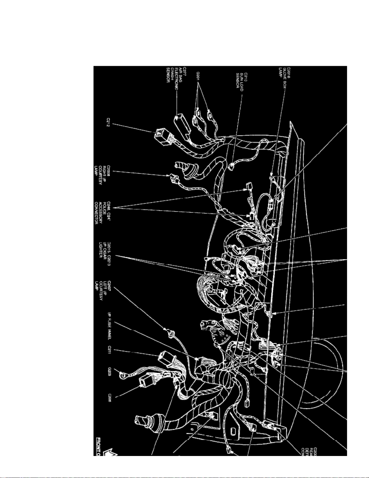
> Relays and Modules > Relays and Modules - Accessories and Optional Equipment > Alarm Module, (Vehicle Antitheft) > Component Information > Locations > Passive Anti-Theft System Module
Alarm Module: LocationsPassive Anti-Theft System Module
Page 3

Instrument Panel View
The Passive Anti-Theft System Module is located at the LH side of the instrument panel.
Page 4
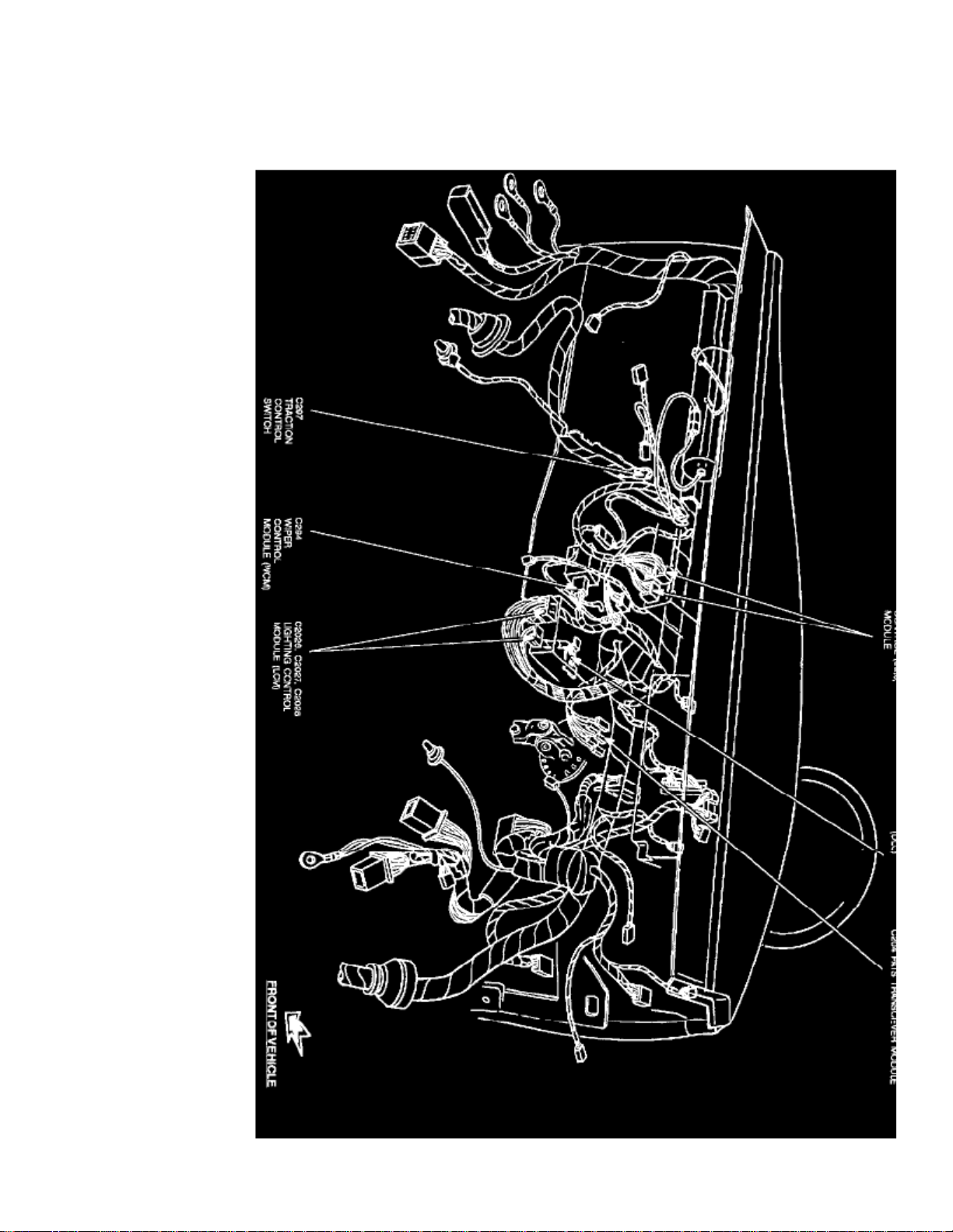
> Relays and Modules > Relays and Modules - Accessories and Optional Equipment > Alarm Module, (Vehicle Antitheft) > Component Information > Locations > Passive Anti-Theft System Module > Page 8
Alarm Module: LocationsPassive Anti-Theft System Transceiver Module
Page 5

Instrument Panel View
The Passive Anti-Theft System Transceiver Module is located at the LH side of the instrument panel.
Page 6
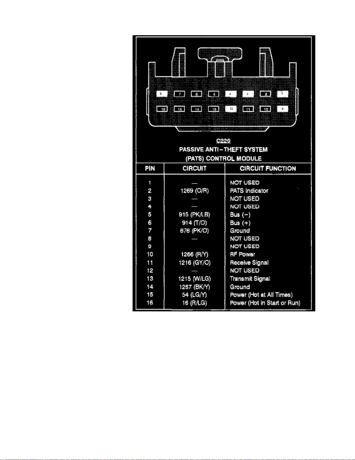
> Relays and Modules > Relays and Modules - Accessories and Optional Equipment > Alarm Module, (Vehicle Antitheft) > Component Information > Diagrams > Anti-Theft Controller Module
Passive Anti-Theft System Control Module
Page 7

Page 8
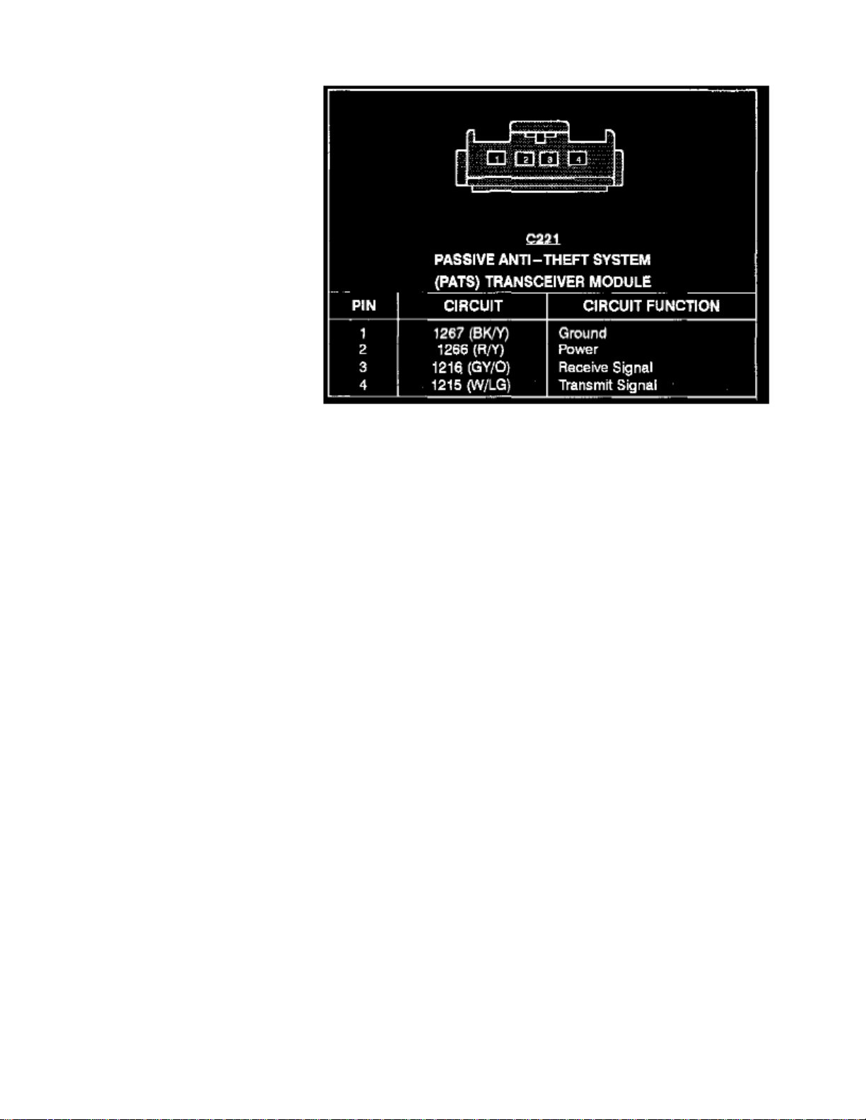
> Relays and Modules > Relays and Modules - Accessories and Optional Equipment > Alarm Module, (Vehicle Antitheft) > Component Information > Diagrams > Anti-Theft Controller Module > Page 11
Passive Anti-Theft System Transceiver Module
Page 9

Page 10
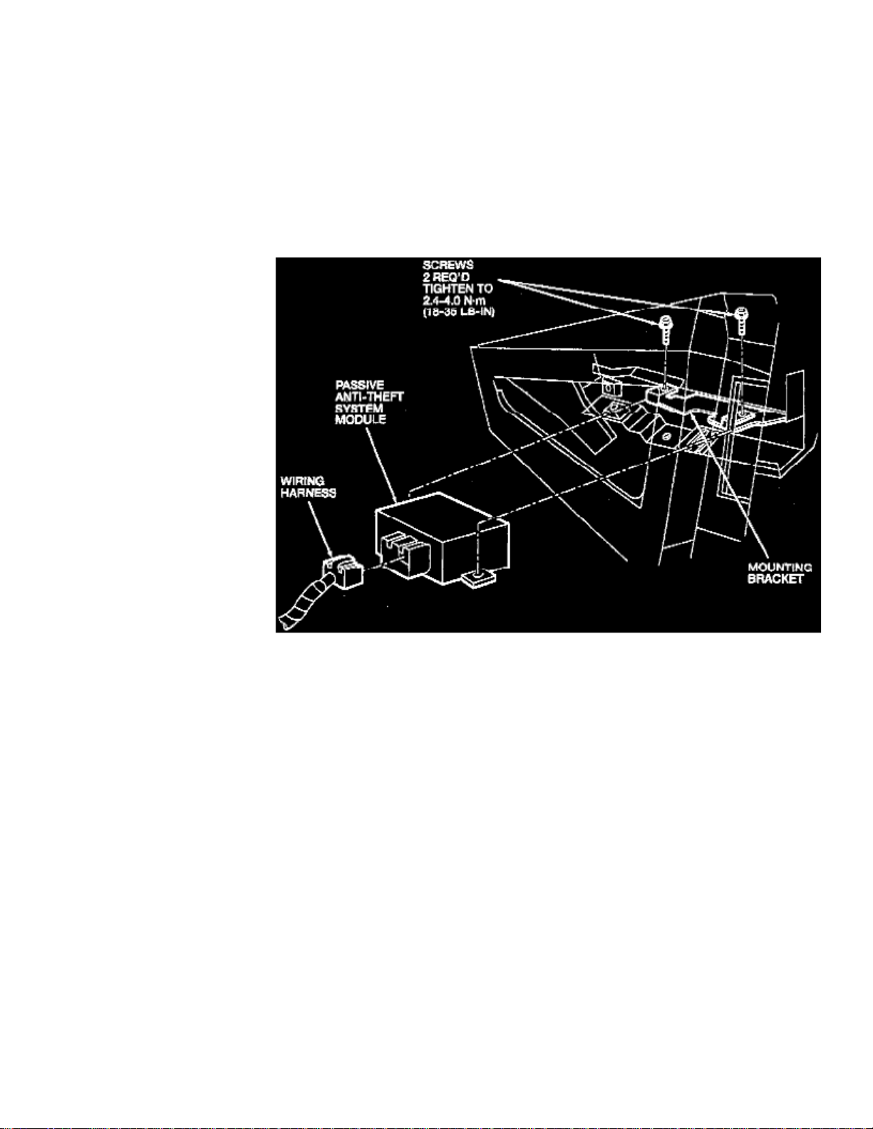
> Relays and Modules > Relays and Modules - Accessories and Optional Equipment > Alarm Module, (Vehicle Antitheft) > Component Information > Diagrams > Page 12
Alarm Module: Service and Repair
Removal
1. Disconnect battery ground cable.2. Remove the steering column opening cover assembly and reinforcement to access passive anti-theft system (PATS) module located to right of fuse
junction panel.
3. Remove three fasteners retaining module and bracket and one fastener attaching metal brace near module. 4. Disconnect main wiring harness connector and remove PATS module and mounting bracket.
PATS Control Module
Installation
Note:
The PATS module must be reconfigured after replacement. Two encoded keys must be cycled in ignition first and then Pinpoint Test B2139must be followed to initialize module.
into the control module.
4. Configure the module as necessary (B2139). 5. To program additional keys, follow Key Programming Program a Key using Two Programmed Keys. See: Accessories and Optional
Equipment/Antitheft and Alarm Systems/Service and Repair
Page 11

1. To install, reverse the removal procedure. 2. Tighten all three screws to 3. Install an encoded ignition key (with correct vehicle mechanical key cut) into ignition switch and turn to the RUN position to program the first key2.4-4.0 Nm (22-35 lb-in).
Page 12
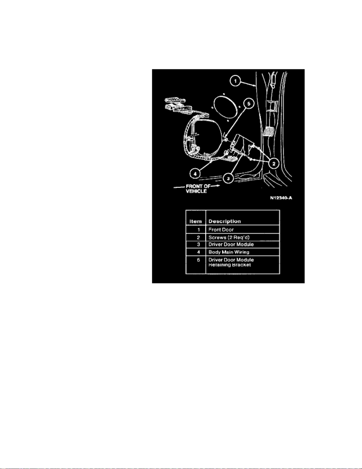
> Relays and Modules > Relays and Modules - Accessories and Optional Equipment > Driver's Door Module <--> [Keyless Entry Module] > Component Information > Service and Repair
Driver's Door Module: Service and Repair
REMOVAL
1. Disconnect battery ground cable.
2. Remove LH front door trim panel.3. Disconnect body main wiring from driver door module.4. Remove two screws retaining driver door module to front door. Remove driver door module.
INSTALLATION
1. Follow removal procedure in reverse order.
Page 13

Page 14
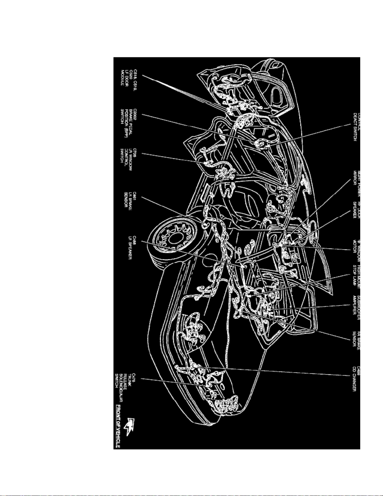
> Relays and Modules > Relays and Modules - Body and Frame > Door Module > Component Information > Locations
Door Module: Locations
Page 15

Full Body View
The Left Front Door Module is located in the driver's door.
Page 16
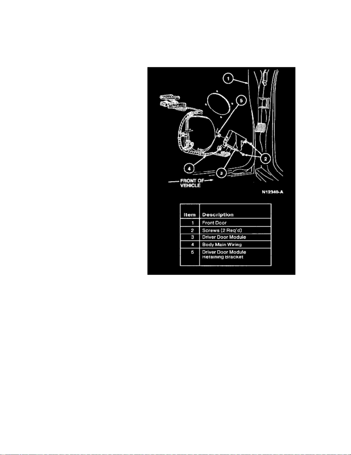
> Relays and Modules > Relays and Modules - Body and Frame > Driver's Door Module <--> [Keyless Entry Module] > Component Information > Service and Repair
Driver's Door Module: Service and Repair
REMOVAL
1. Disconnect battery ground cable.
2. Remove LH front door trim panel.3. Disconnect body main wiring from driver door module.4. Remove two screws retaining driver door module to front door. Remove driver door module.
INSTALLATION
1. Follow removal procedure in reverse order.
Page 17

Page 18
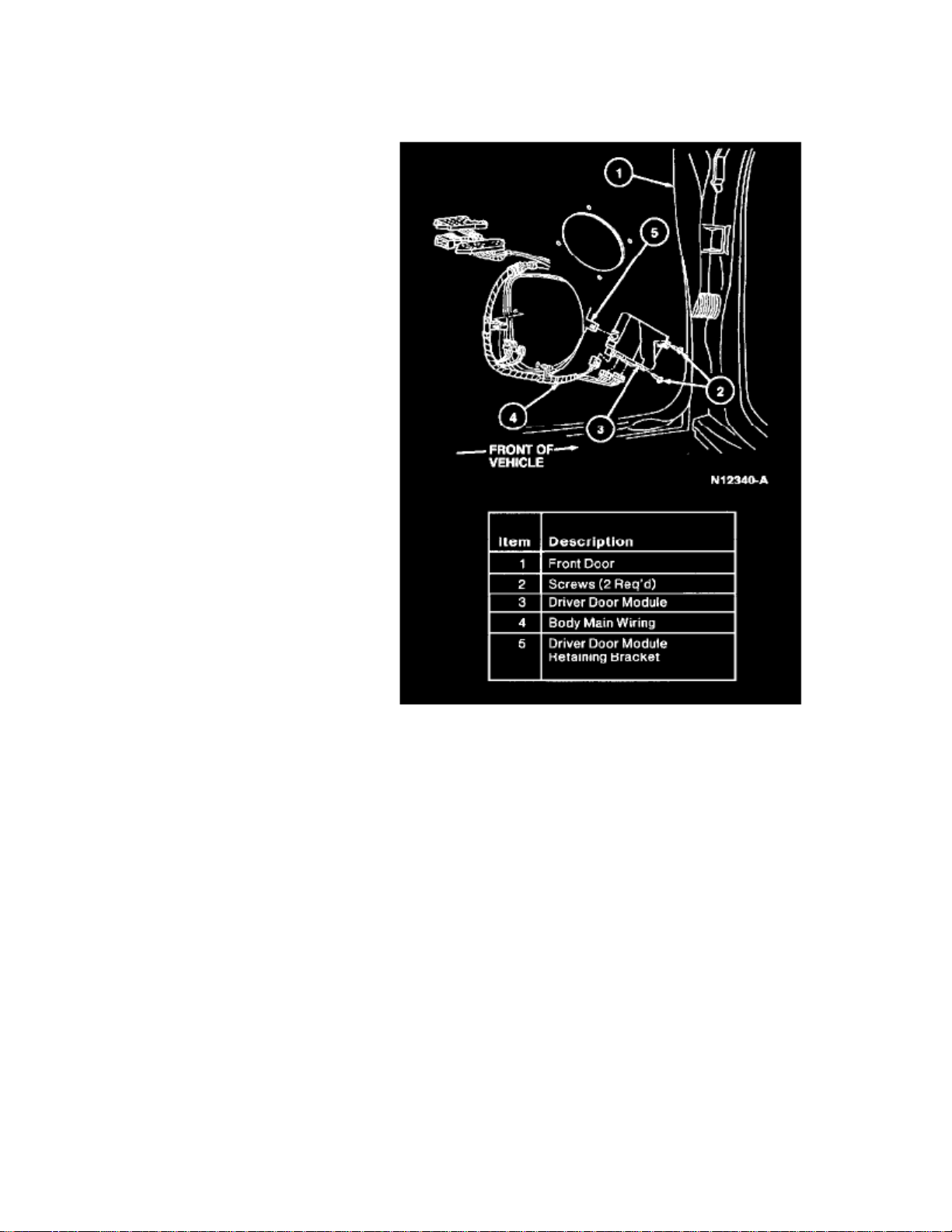
> Relays and Modules > Relays and Modules - Body and Frame > Power Door Lock Control Module > Component Information > Locations
Power Door Lock Control Module: Locations
The Driver's Door Module is located in center of the LH front door.
Page 19

Page 20
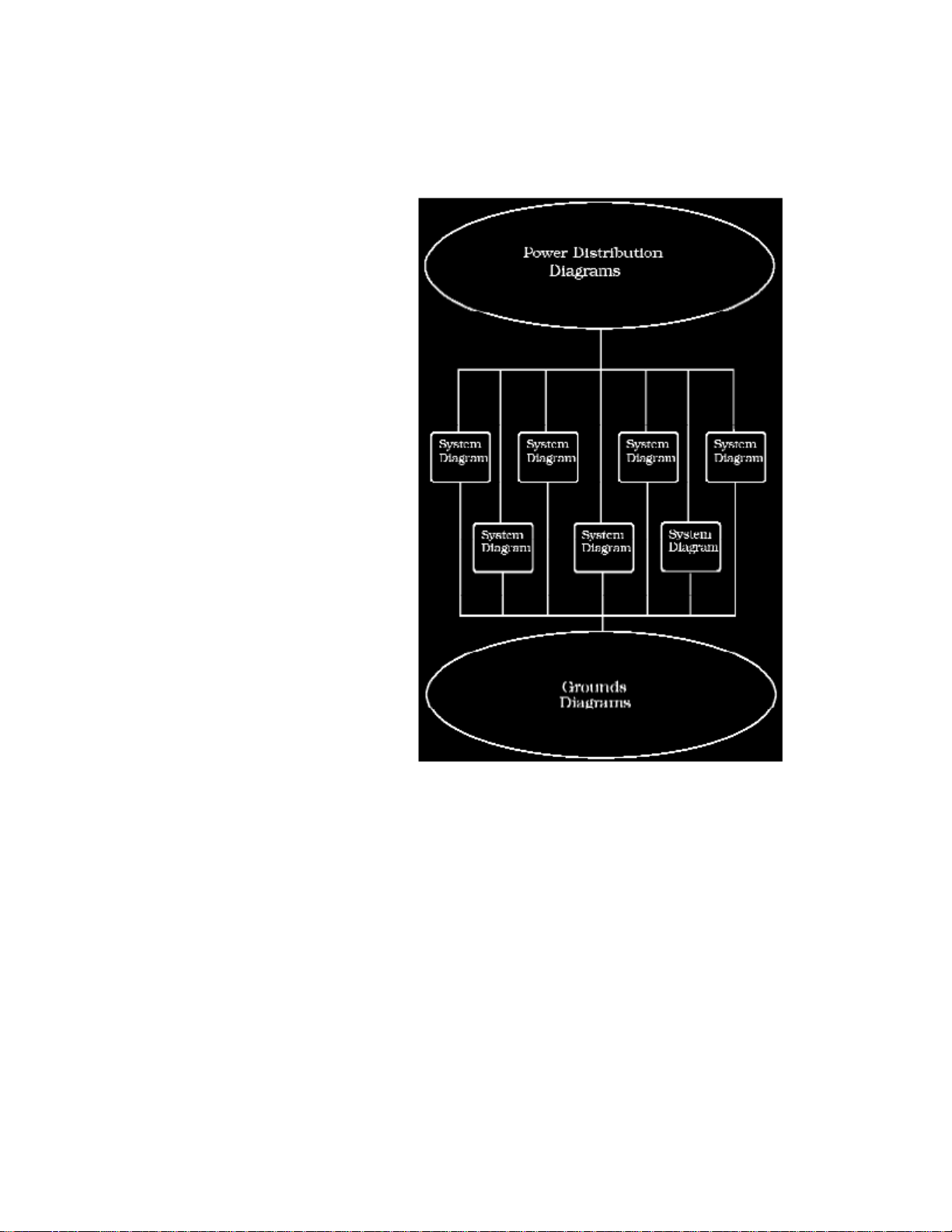
> Relays and Modules > Relays and Modules - Body and Frame > Power Door Lock Control Module > Component Information > Diagrams > Diagram Information and Instructions
Power Door Lock Control Module: Diagram Information and Instructions
How to Find and Use These Diagrams
Diagrams are presented in three main categories:
- Power Distribution Diagrams
- System Diagrams
- Grounds Diagrams
Page 21

> Relays and Modules > Relays and Modules - Body and Frame > Power Door Lock Control Module > Component Information > Diagrams > Diagram Information and
Instructions > Page 28
Crown Victoria V8-281 4.6L SFI (1998)
Page 22
Page 23

> Relays and Modules > Relays and Modules - Body and Frame > Power Door Lock Control Module > Component Information > Diagrams > Diagram Information and
Instructions > Page 29
Crown Victoria V8-281 4.6L SFI (1998)
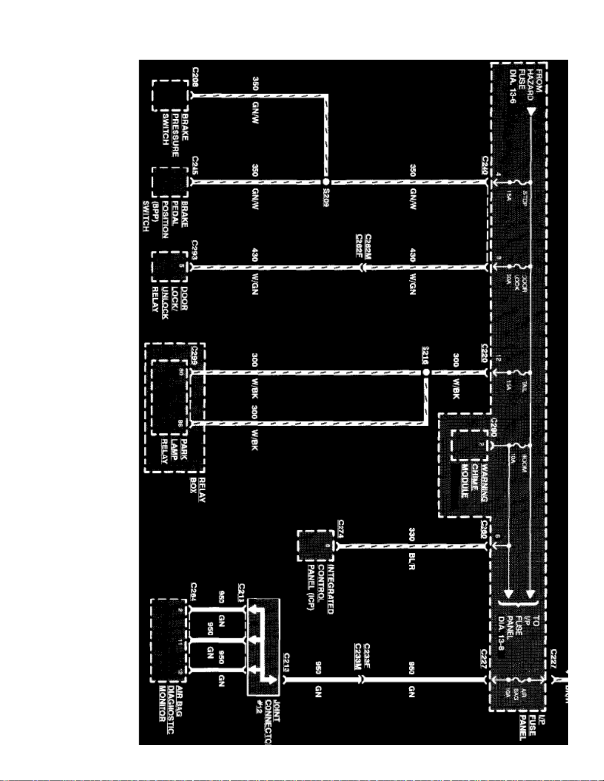
Sample Power Distribution Diagram
Power Distribution Diagrams
Provide the circuit details of how the system diagrams are powered. The power distribution source is shown at the top of a diagram page. All wires,connectors, and splices are shown in the same manner that the current flows, ending at the component/system being powered near the bottom of adiagram page. Circuits that go from one diagram page to another will be marked with large arrow heads.
The power distribution diagrams can be found at Starting and Charging/Power and Ground Distribution.
Page 24
Page 25

> Relays and Modules > Relays and Modules - Body and Frame > Power Door Lock Control Module > Component Information > Diagrams > Diagram Information and
Instructions > Page 30
Crown Victoria V8-281 4.6L SFI (1998)
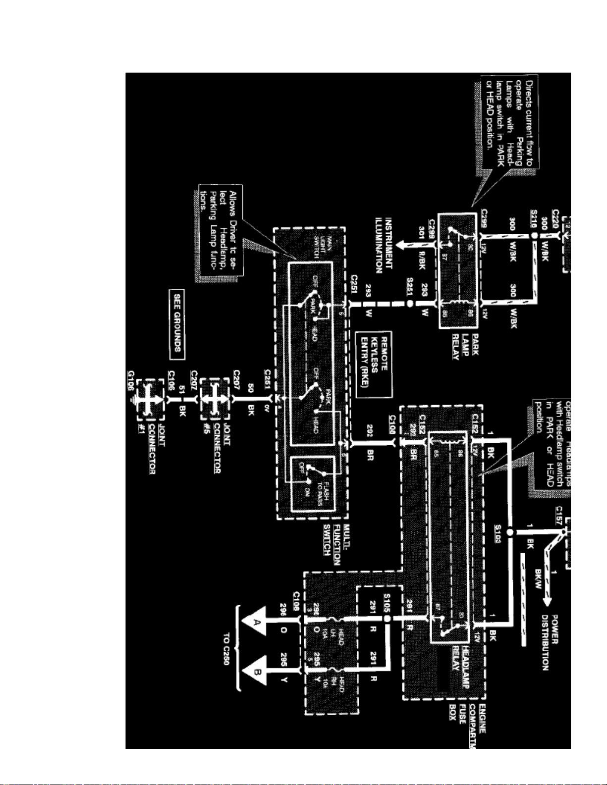
Sample System Diagram
System Diagrams
Components that work together are shown together in a system/subsystem diagram or set of diagrams. The system feed (circuit breaker, fuse, etc.) isshown at the top of a diagram page. All wires, connectors, components, and splices are shown in the same manner that the current flows, ending at theground at the bottom of a diagram page. Circuits that go from one diagram page to another will be marked with large arrow heads.
Page 26
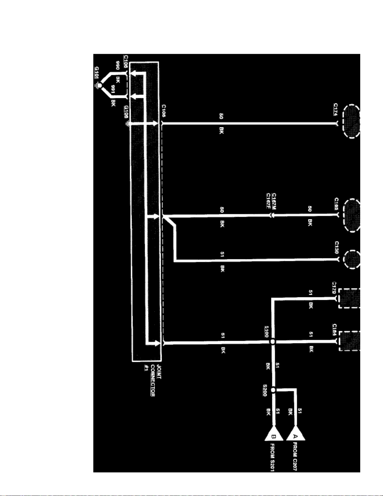
Management, Radio/Stereo, etc.
Page 27

> Relays and Modules > Relays and Modules - Body and Frame > Power Door Lock Control Module > Component Information > Diagrams > Diagram Information and
Instructions > Page 31
Crown Victoria V8-281 4.6L SFI (1998)
Sample Grounds Diagram
Grounds Diagrams
Provide the circuit details of how the system diagrams are grounded. This information is useful for checking interconnections of the grounding circuitsof different systems. The components/systems being grounded are shown at the top of a diagram page. All wires, connectors, and splices are shown in thesame manner that the current flows, ending at the ground at the bottom of a diagram page. Circuits that go from one diagram page to another will bemarked with large arrow heads.
The grounds diagrams can be found at Starting and Charging/Power and Ground Distribution.
Symbol Identification
Page 28
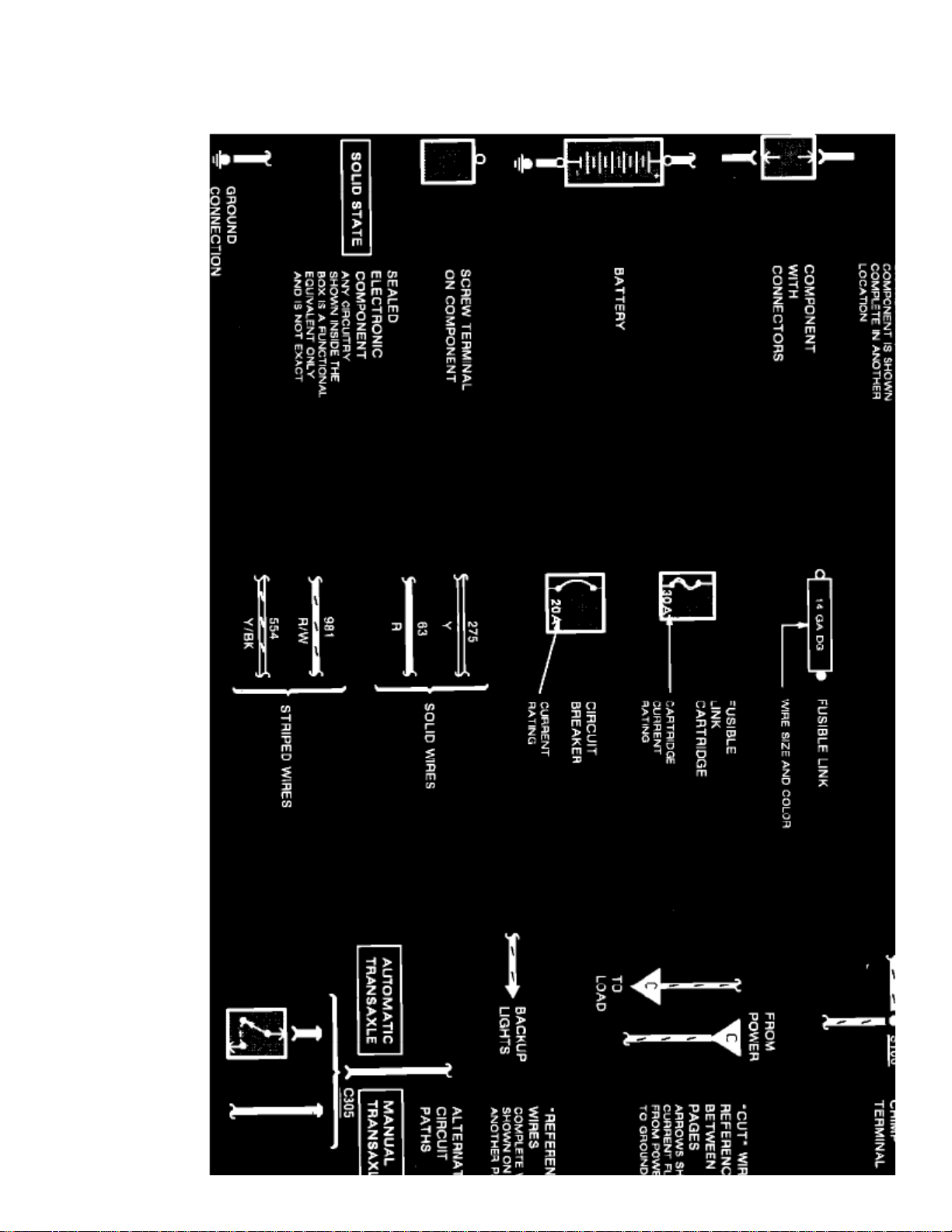
ELECTRICAL SYMBOLS
Page 29

> Relays and Modules > Relays and Modules - Body and Frame > Power Door Lock Control Module > Component Information > Diagrams > Diagram Information and
Instructions > Page 32
Crown Victoria V8-281 4.6L SFI (1998)
Electrical Symbols
Page 30
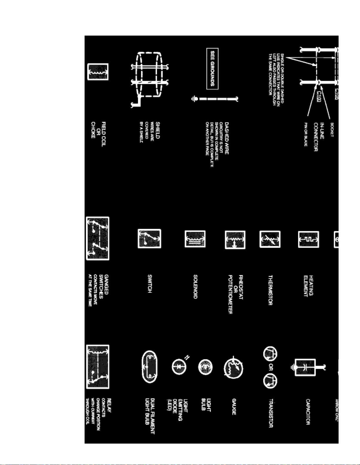
Page 31

> Relays and Modules > Relays and Modules - Body and Frame > Power Door Lock Control Module > Component Information > Diagrams > Diagram Information and
Instructions > Page 33
Crown Victoria V8-281 4.6L SFI (1998)
Electrical Symbols
VACUUM SYMBOLS
Page 32
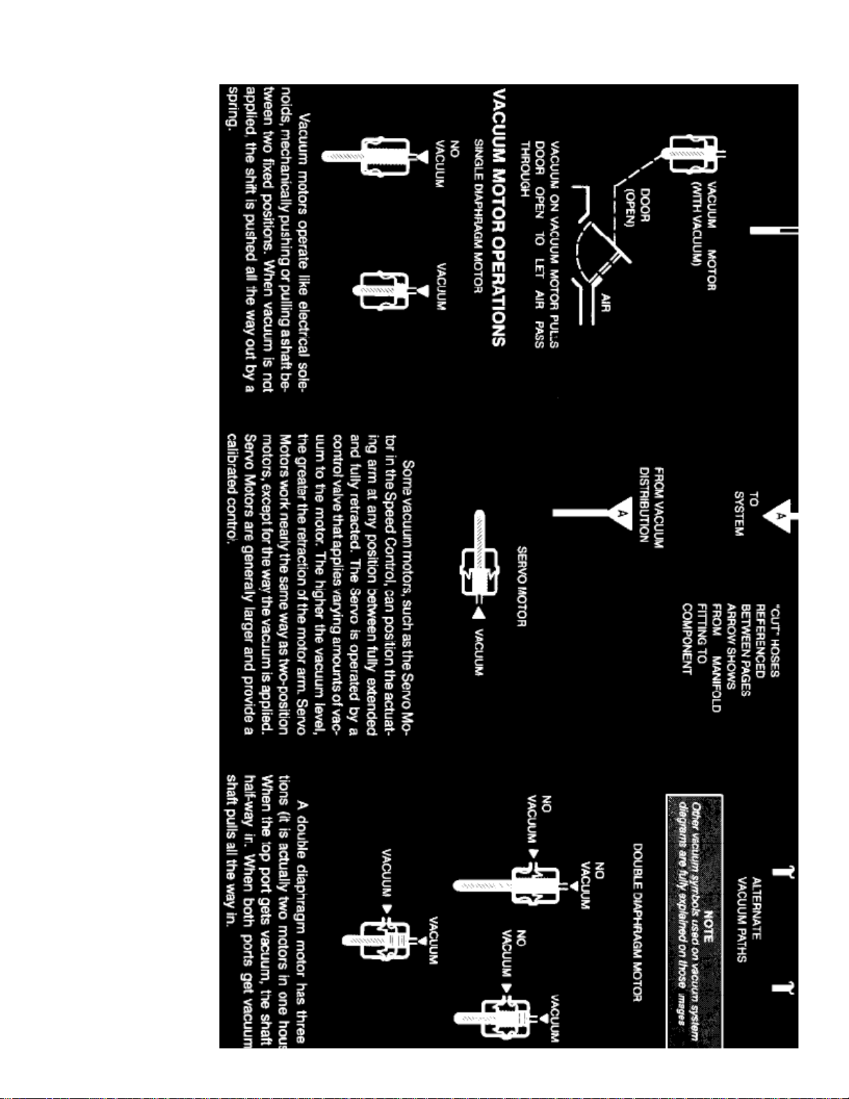
Page 33

> Relays and Modules > Relays and Modules - Body and Frame > Power Door Lock Control Module > Component Information > Diagrams > Diagram Information and
Instructions > Page 34
Crown Victoria V8-281 4.6L SFI (1998)
Vacuum Symbols
Wire Color Code Identification
BK
BL
BR
: Black: Blue: Brown: Dark BlueDB
Page 34

DG
GY
GN
LB
LG
PK
O
P
R
T
V
W
: Dark Green: Gray: Green: Light Blue: Light Green: Pink: Orange: Purple: Red: Tan: Violet: White: YellowY
NOTE:
Whenever a wire is labeled with two colors, the first color listed is the basic color of the wire, and the second color listed is the stripe marking ofthe wire.
Page 35

Page 36
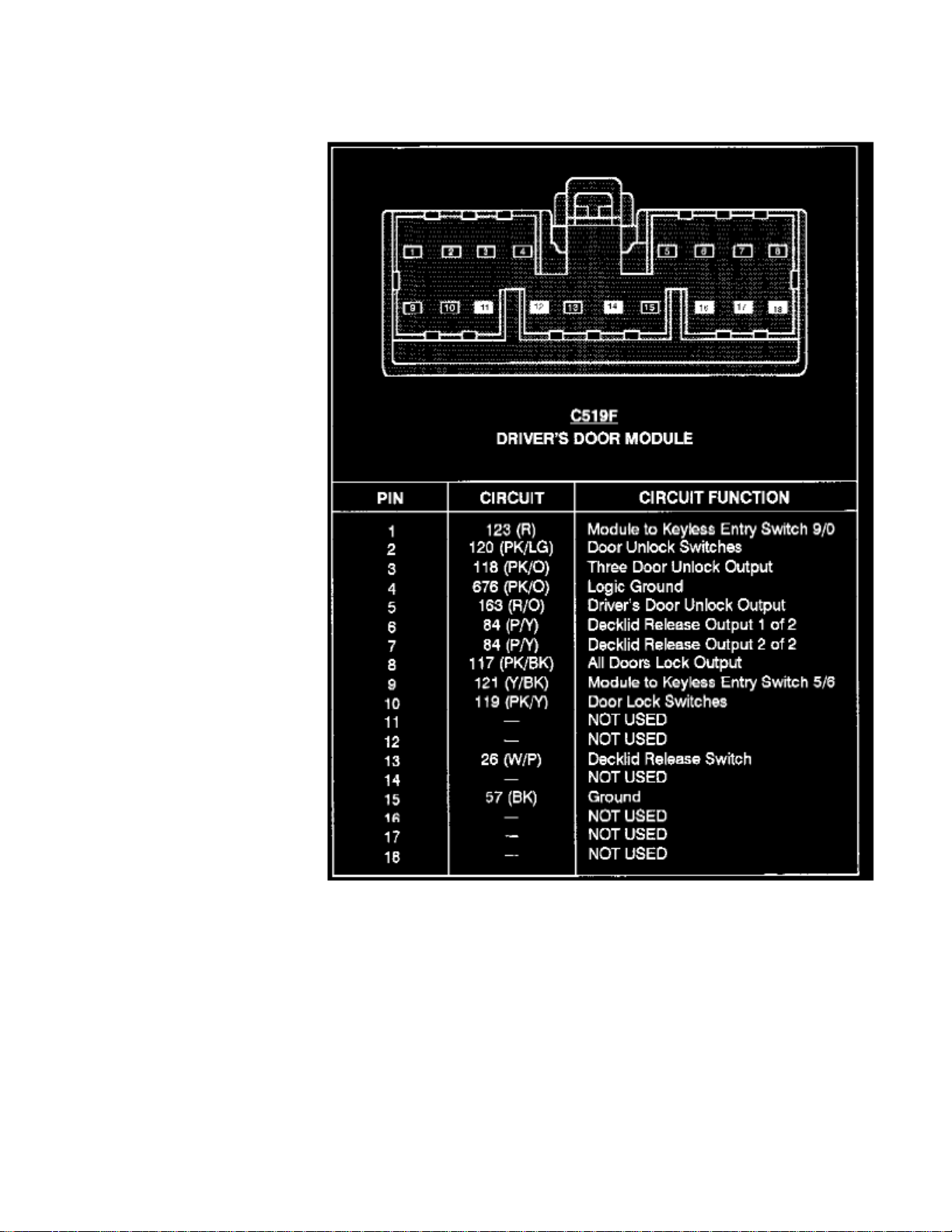
> Relays and Modules > Relays and Modules - Body and Frame > Power Door Lock Control Module > Component Information > Diagrams > Diagram Information and Instructions > Page 35
Power Door Lock Control Module: Connector Views
Driver's Door Module (C519)
Page 37

> Relays and Modules > Relays and Modules - Body and Frame > Power Door Lock Control Module > Component Information > Diagrams > Diagram Information and
Instructions > Page 36
Crown Victoria V8-281 4.6L SFI (1998)
Page 38
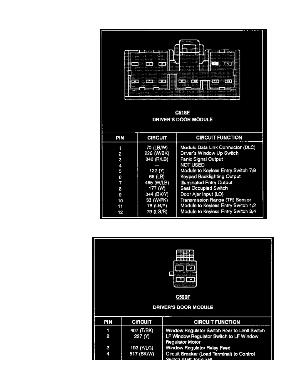
Driver's Door Module (C518)
Page 39

Driver's Door Module (C520)
Page 40
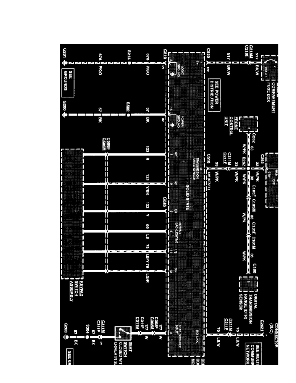
> Relays and Modules > Relays and Modules - Body and Frame > Power Door Lock Control Module > Component Information > Diagrams > Diagram Information and Instructions > Page 37
Power Door Lock Control Module: Electrical Diagrams
Page 41

> Relays and Modules > Relays and Modules - Body and Frame > Power Door Lock Control Module > Component Information > Diagrams > Diagram Information and
Instructions > Page 38
Crown Victoria V8-281 4.6L SFI (1998)
Driver's Door Module (Part 1 Of 3)
Page 42
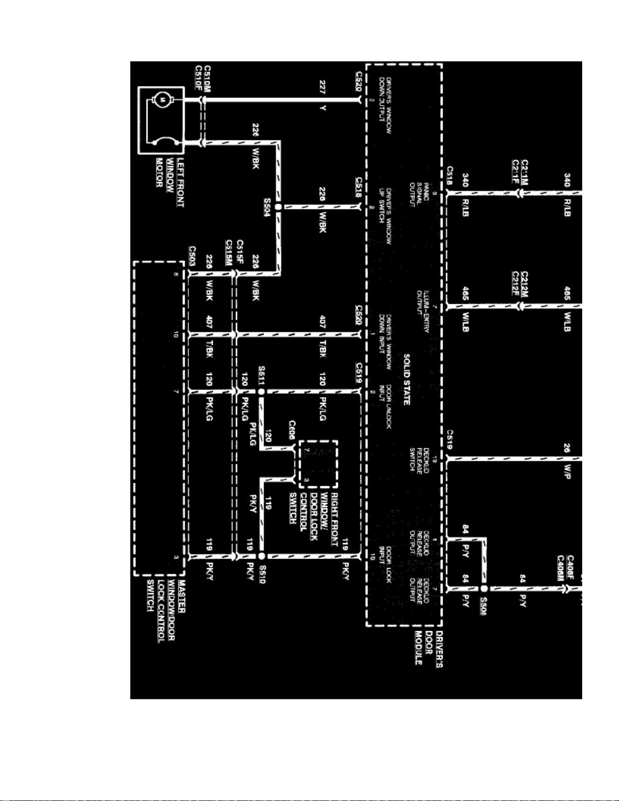
Driver's Door Module (Part 2 Of 3)
Page 43

> Relays and Modules > Relays and Modules - Body and Frame > Power Door Lock Control Module > Component Information > Diagrams > Diagram Information and
Instructions > Page 39
Crown Victoria V8-281 4.6L SFI (1998)
Page 44
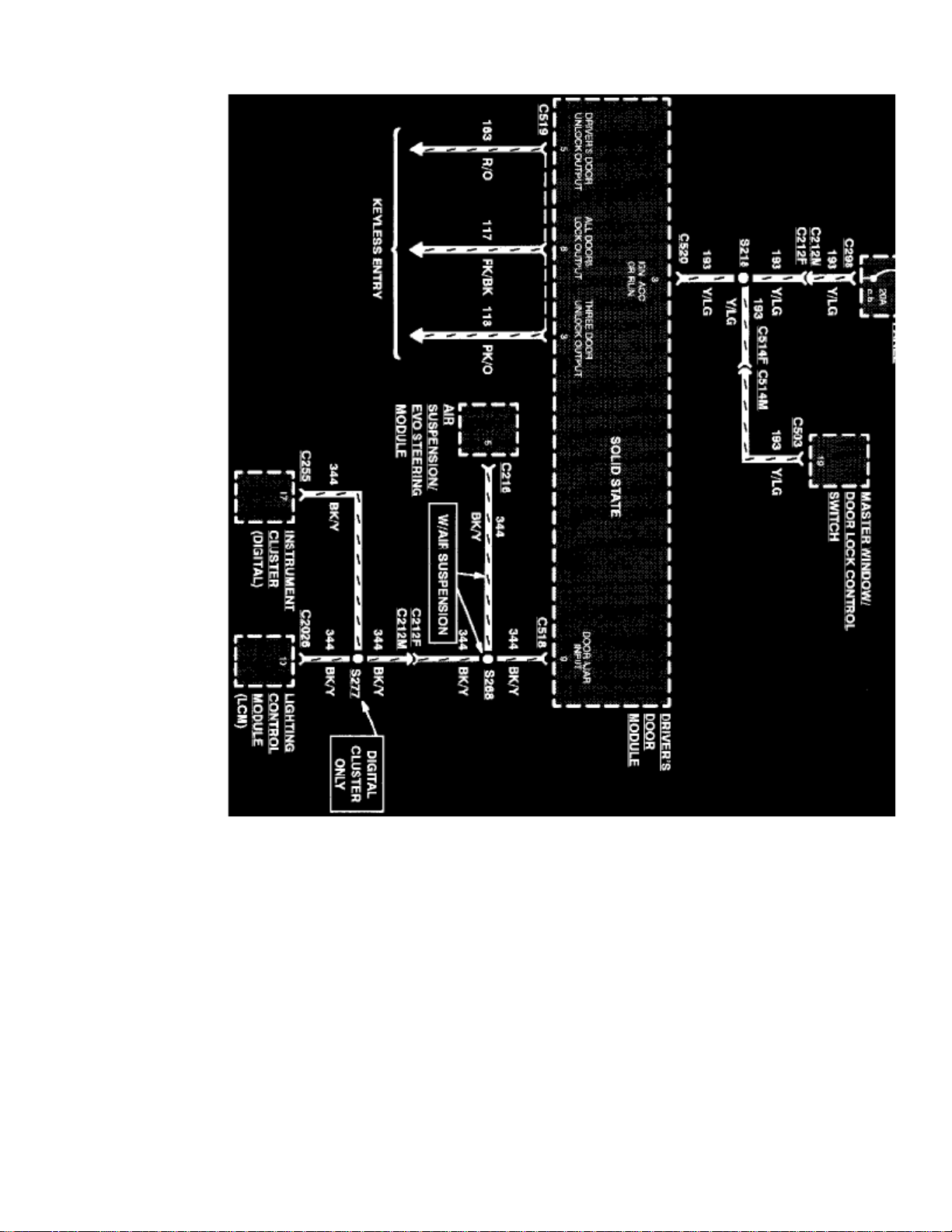
Driver's Door Module (Part 3 Of 3)
Page 45

Page 46
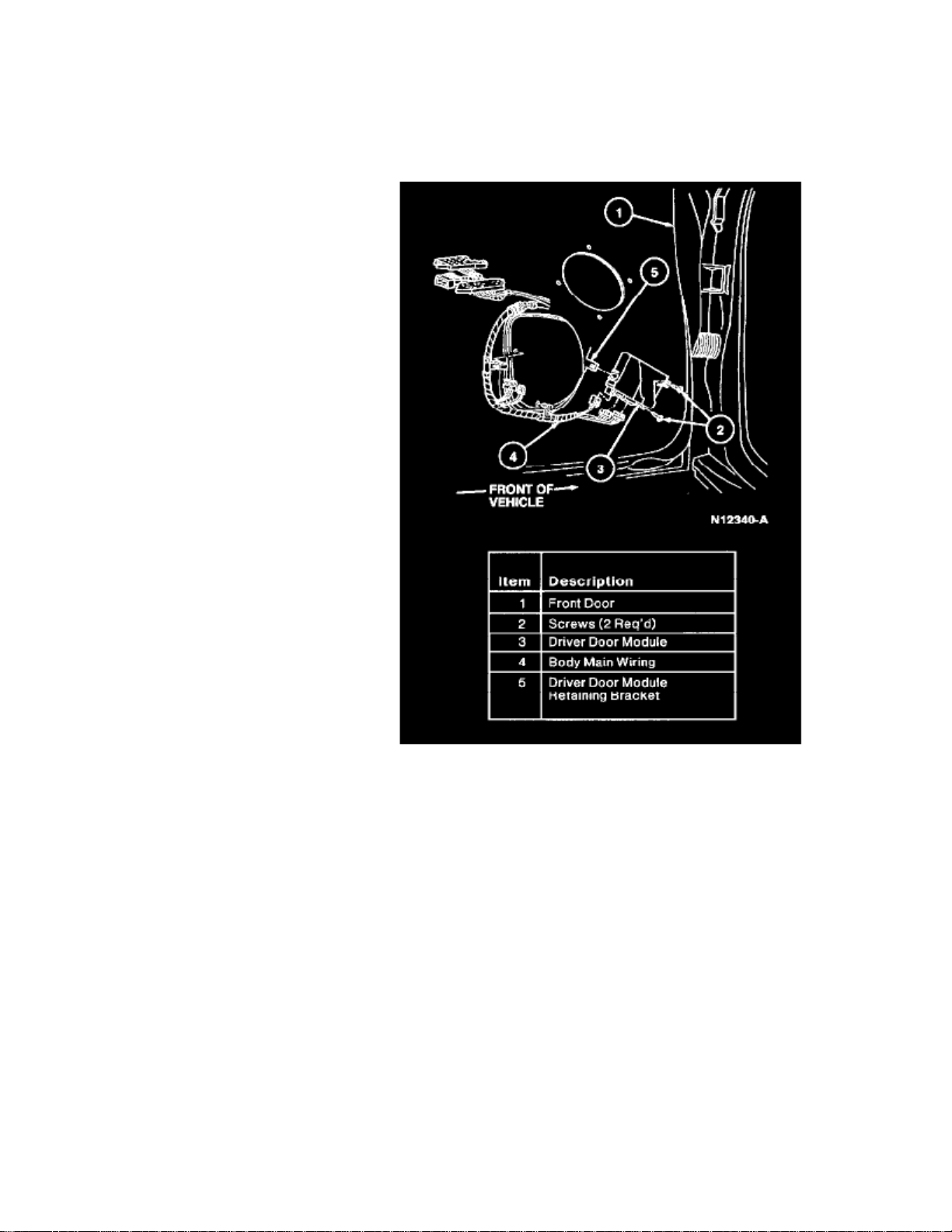
> Relays and Modules > Relays and Modules - Body and Frame > Power Door Lock Control Module > Component Information > Diagrams > Page 40
Power Door Lock Control Module: Service and Repair
REMOVAL
1. Disconnect battery ground cable.
2. Remove LH front door trim panel.3. Disconnect body main wiring from driver door module.4. Remove two screws retaining driver door module to front door. Remove driver door module.
INSTALLATION
1. Follow removal procedure in reverse order.
Page 47

Page 48
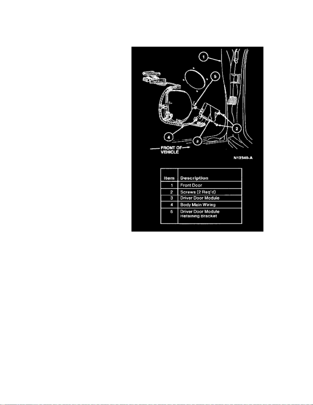
> Relays and Modules > Relays and Modules - Body and Frame > Power Mirror Control Module > Component Information > Locations
Power Mirror Control Module: Locations
The Driver's Door Module is located in center of the LH front door.
Page 49

Page 50
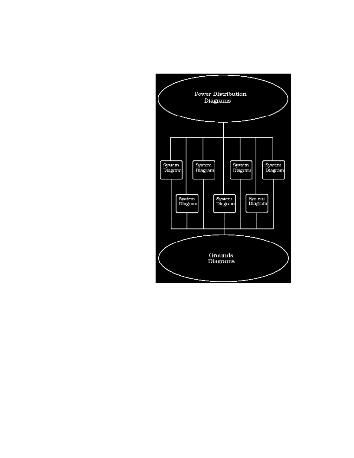
> Relays and Modules > Relays and Modules - Body and Frame > Power Mirror Control Module > Component Information > Diagrams > Diagram Information and Instructions
Power Mirror Control Module: Diagram Information and Instructions
How to Find and Use These Diagrams
Diagrams are presented in three main categories:
- Power Distribution Diagrams
- System Diagrams
- Grounds Diagrams
Page 51

> Relays and Modules > Relays and Modules - Body and Frame > Power Mirror Control Module > Component Information > Diagrams > Diagram Information and
Instructions > Page 46
Crown Victoria V8-281 4.6L SFI (1998)
Page 52
Page 53

> Relays and Modules > Relays and Modules - Body and Frame > Power Mirror Control Module > Component Information > Diagrams > Diagram Information and
Instructions > Page 47
Crown Victoria V8-281 4.6L SFI (1998)
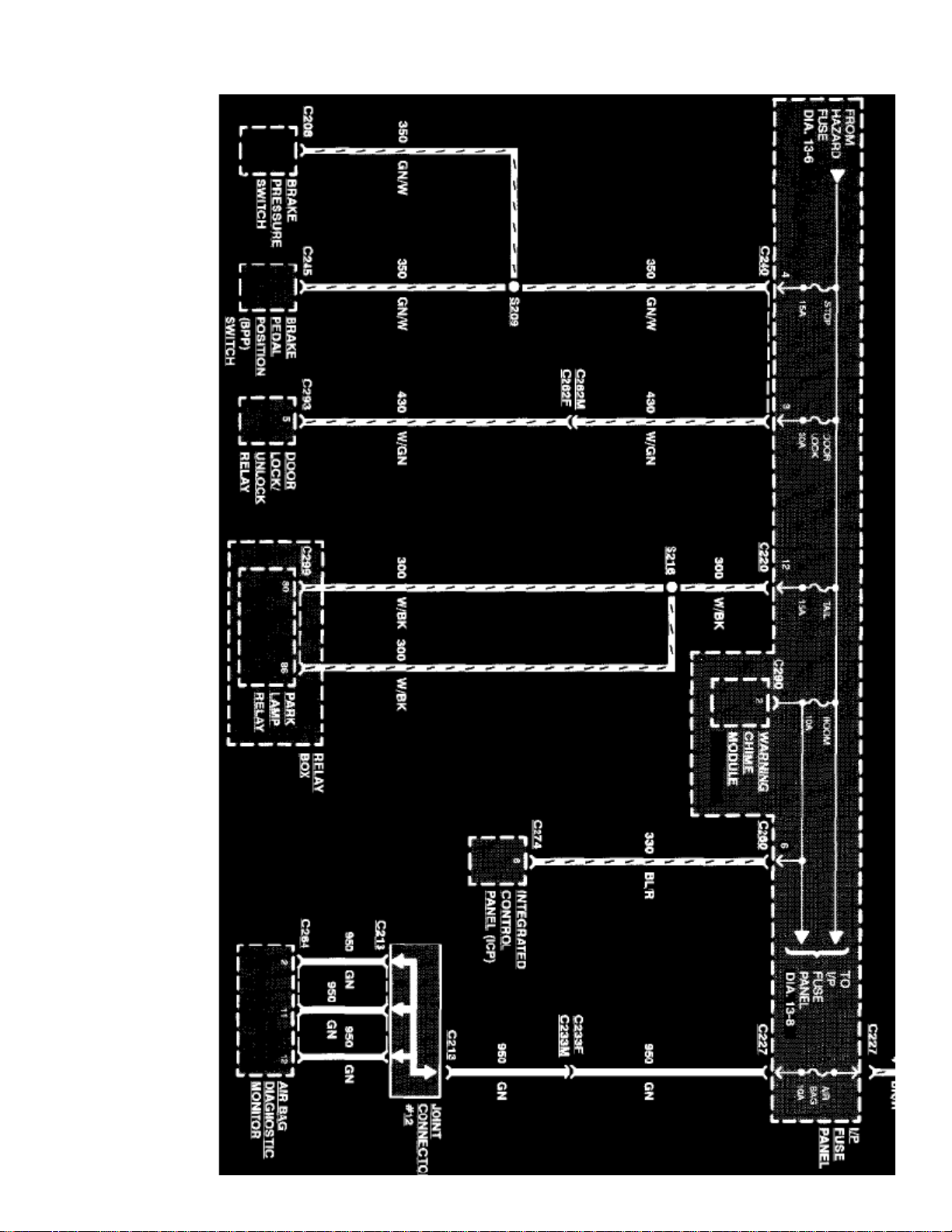
Sample Power Distribution Diagram
Power Distribution Diagrams
Provide the circuit details of how the system diagrams are powered. The power distribution source is shown at the top of a diagram page. All wires,connectors, and splices are shown in the same manner that the current flows, ending at the component/system being powered near the bottom of adiagram page. Circuits that go from one diagram page to another will be marked with large arrow heads.
The power distribution diagrams can be found at Starting and Charging/Power and Ground Distribution.
Page 54
Page 55

> Relays and Modules > Relays and Modules - Body and Frame > Power Mirror Control Module > Component Information > Diagrams > Diagram Information and
Instructions > Page 48
Crown Victoria V8-281 4.6L SFI (1998)
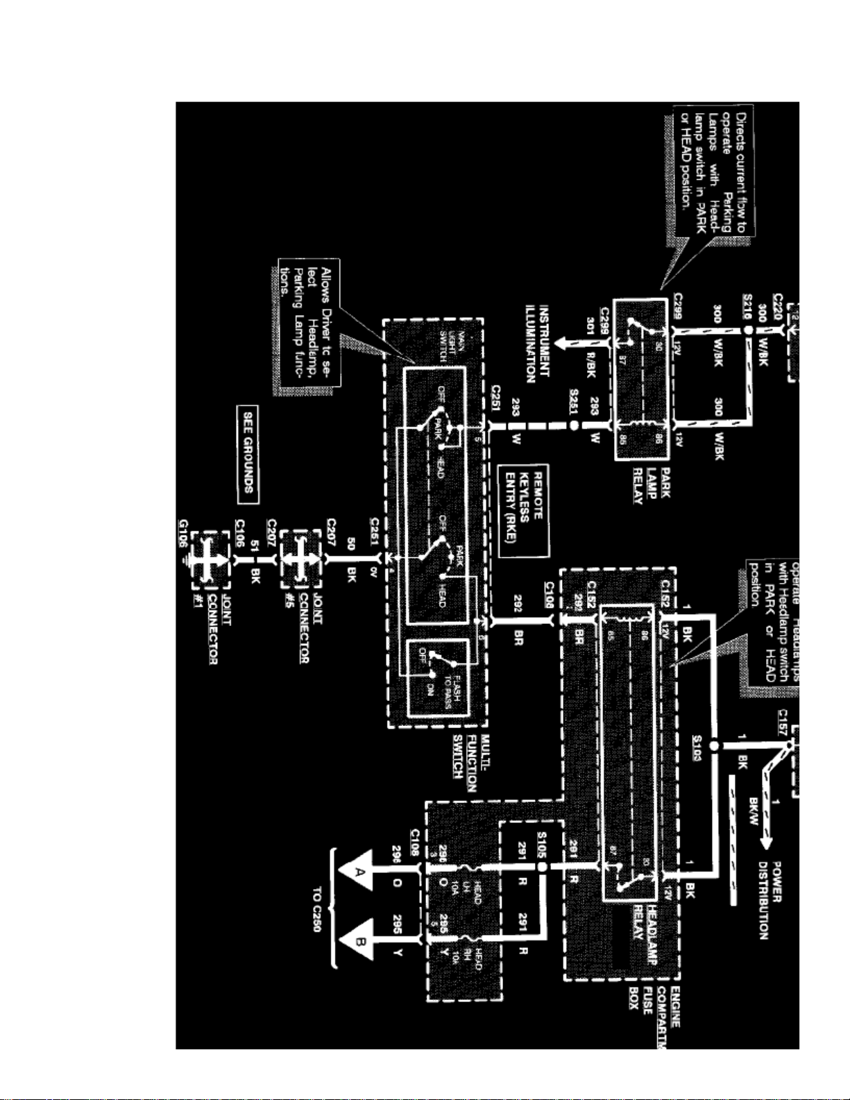
Sample System Diagram
System Diagrams
Components that work together are shown together in a system/subsystem diagram or set of diagrams. The system feed (circuit breaker, fuse, etc.) isshown at the top of a diagram page. All wires, connectors, components, and splices are shown in the same manner that the current flows, ending at theground at the bottom of a diagram page. Circuits that go from one diagram page to another will be marked with large arrow heads.
Page 56
Management, Radio/Stereo, etc.
Page 57

> Relays and Modules > Relays and Modules - Body and Frame > Power Mirror Control Module > Component Information > Diagrams > Diagram Information and
Instructions > Page 49
Crown Victoria V8-281 4.6L SFI (1998)
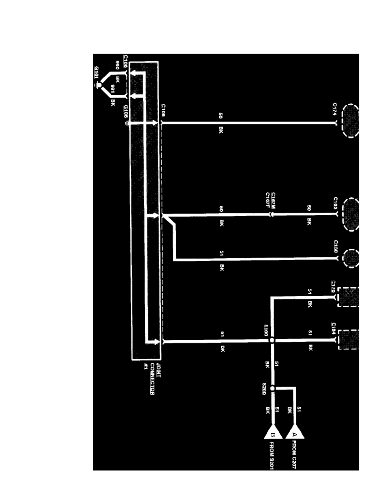
Sample Grounds Diagram
Grounds Diagrams
Provide the circuit details of how the system diagrams are grounded. This information is useful for checking interconnections of the grounding circuitsof different systems. The components/systems being grounded are shown at the top of a diagram page. All wires, connectors, and splices are shown in thesame manner that the current flows, ending at the ground at the bottom of a diagram page. Circuits that go from one diagram page to another will bemarked with large arrow heads.
The grounds diagrams can be found at Starting and Charging/Power and Ground Distribution.
Symbol Identification
Page 58
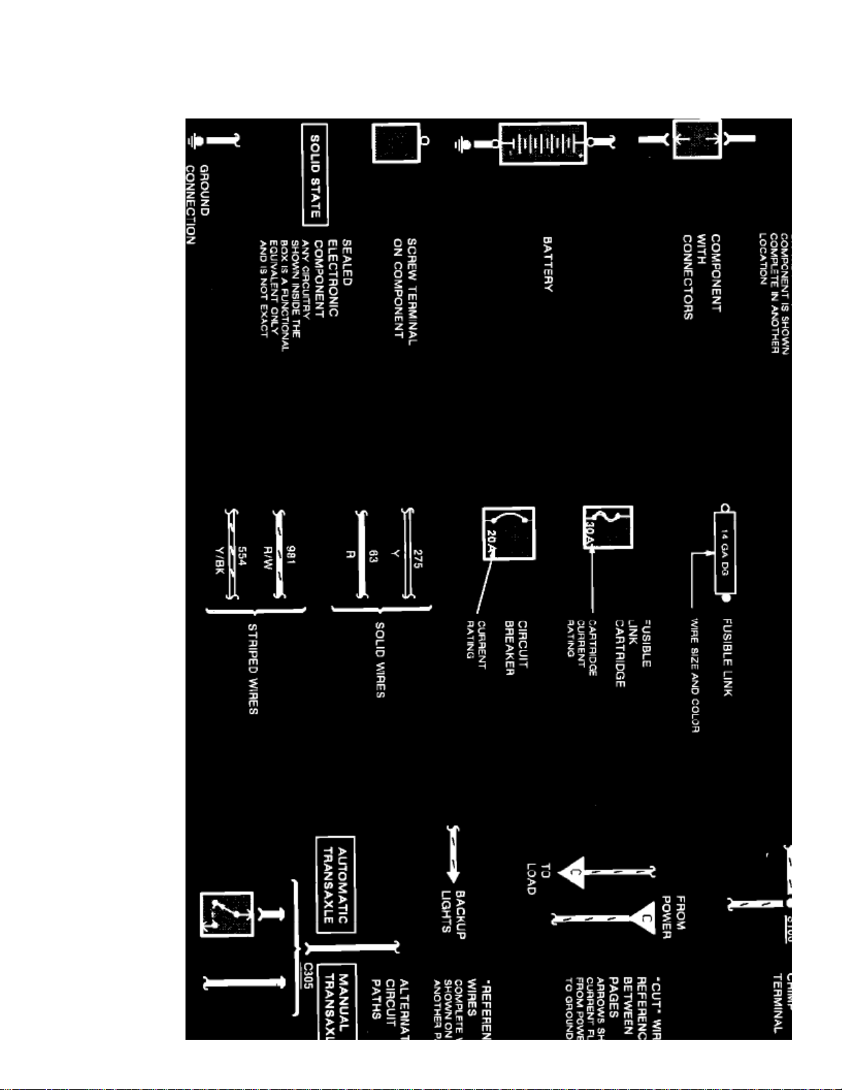
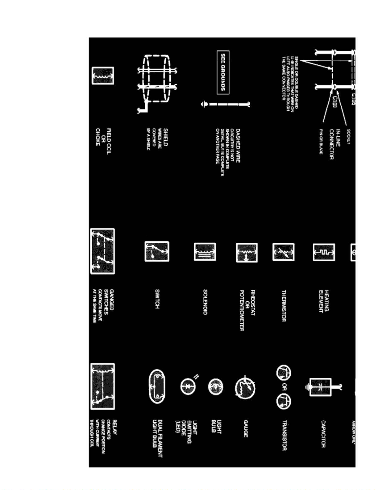
ELECTRICAL SYMBOLS
Page 59

> Relays and Modules > Relays and Modules - Body and Frame > Power Mirror Control Module > Component Information > Diagrams > Diagram Information and
Instructions > Page 50
Crown Victoria V8-281 4.6L SFI (1998)
Electrical Symbols
Page 60
Page 61

> Relays and Modules > Relays and Modules - Body and Frame > Power Mirror Control Module > Component Information > Diagrams > Diagram Information and
Instructions > Page 51
Crown Victoria V8-281 4.6L SFI (1998)
Electrical Symbols
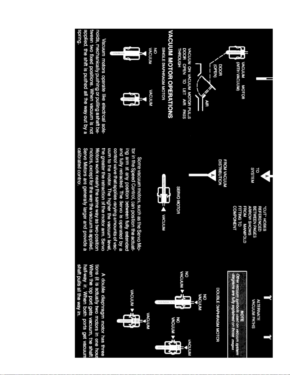
VACUUM SYMBOLS
Page 62
Page 63

> Relays and Modules > Relays and Modules - Body and Frame > Power Mirror Control Module > Component Information > Diagrams > Diagram Information and
Instructions > Page 52
Crown Victoria V8-281 4.6L SFI (1998)
Vacuum Symbols
Wire Color Code Identification
BK
BL
BR
: Black: Blue: Brown: Dark BlueDB
Page 64

DG
GY
GN
LB
LG
PK
O
P
R
T
V
W
: Dark Green: Gray: Green: Light Blue: Light Green: Pink: Orange: Purple: Red: Tan: Violet: White: YellowY
NOTE:
Whenever a wire is labeled with two colors, the first color listed is the basic color of the wire, and the second color listed is the stripe marking ofthe wire.
Page 65

Page 66
> Relays and Modules > Relays and Modules - Body and Frame > Power Mirror Control Module > Component Information > Diagrams > Diagram Information and Instructions > Page 53
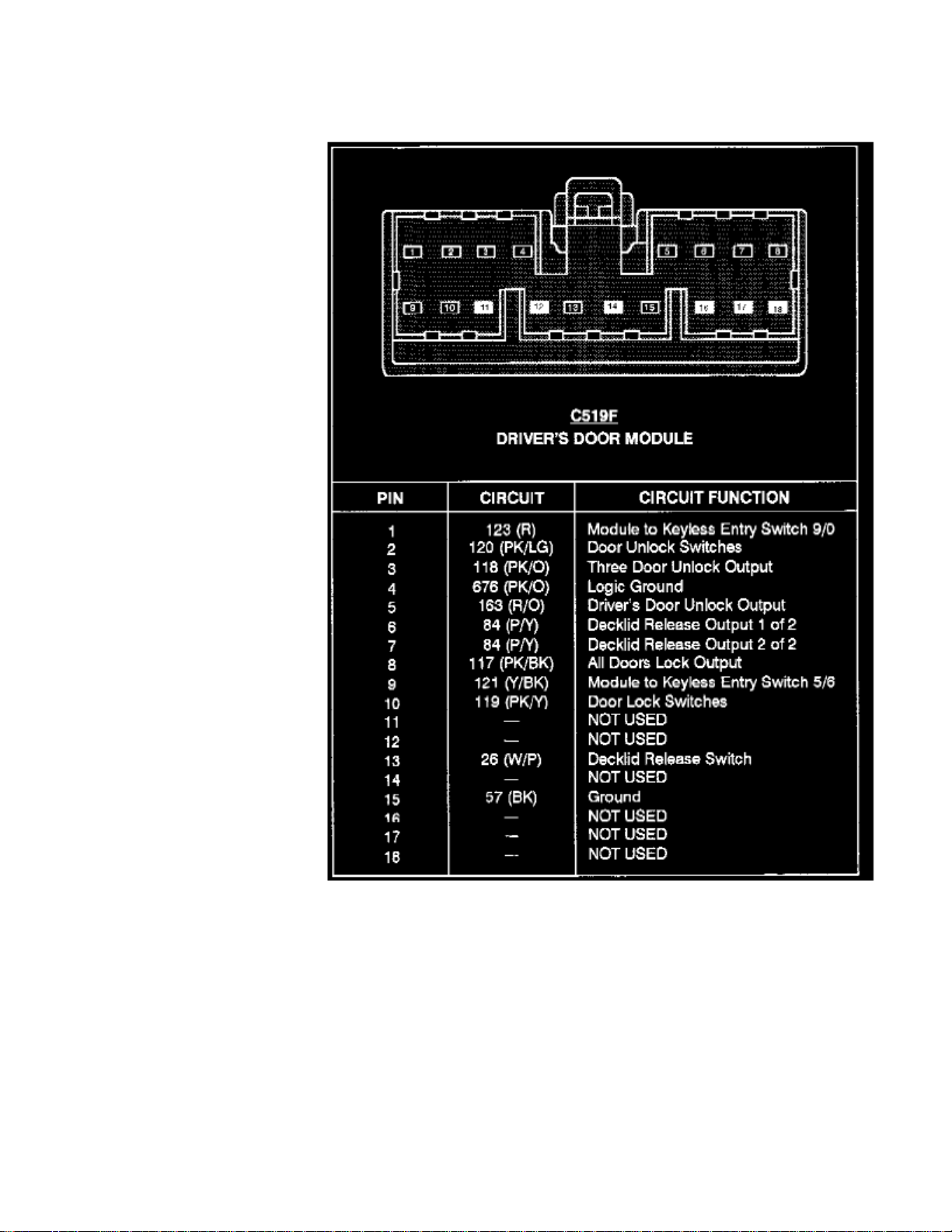
Power Mirror Control Module: Connector Views
Driver's Door Module (C519)
Page 67

> Relays and Modules > Relays and Modules - Body and Frame > Power Mirror Control Module > Component Information > Diagrams > Diagram Information and
Instructions > Page 54
Crown Victoria V8-281 4.6L SFI (1998)
Page 68
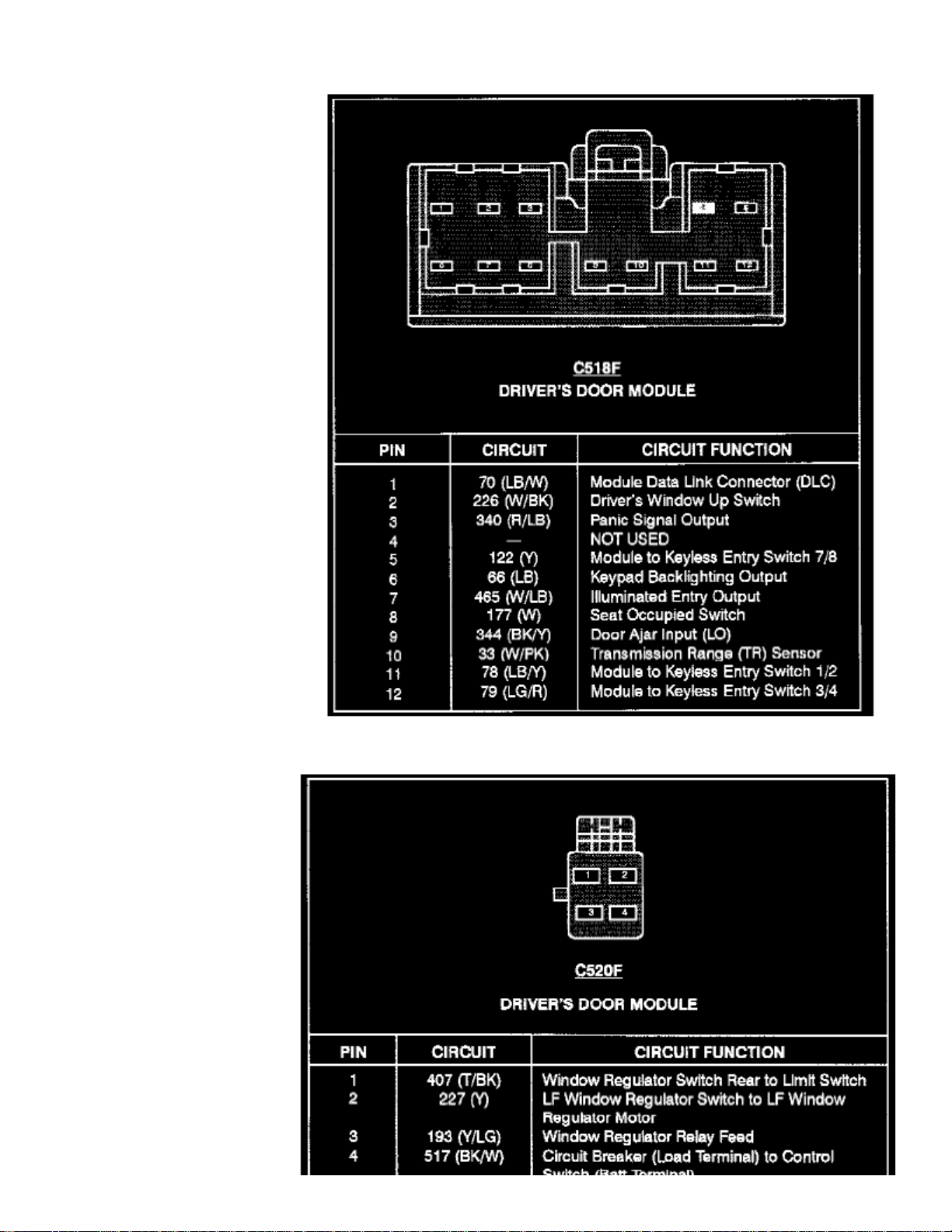
Driver's Door Module (C518)
Page 69

Driver's Door Module (C520)
Page 70
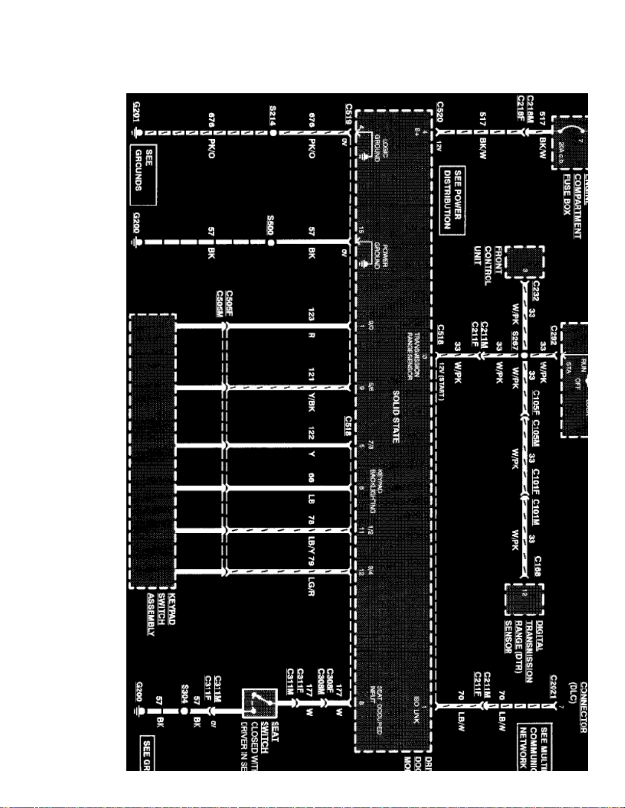
> Relays and Modules > Relays and Modules - Body and Frame > Power Mirror Control Module > Component Information > Diagrams > Diagram Information and Instructions > Page 55
Power Mirror Control Module: Electrical Diagrams
Page 71

> Relays and Modules > Relays and Modules - Body and Frame > Power Mirror Control Module > Component Information > Diagrams > Diagram Information and
Instructions > Page 56
Crown Victoria V8-281 4.6L SFI (1998)
Driver's Door Module (Part 1 Of 3)
Page 72
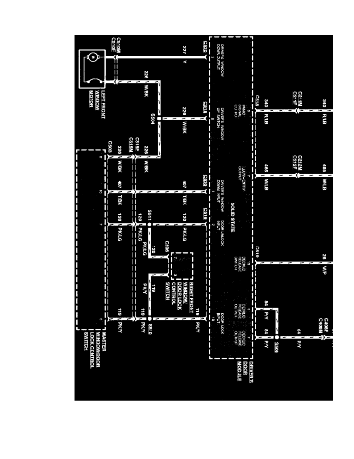
Driver's Door Module (Part 2 Of 3)
Page 73

> Relays and Modules > Relays and Modules - Body and Frame > Power Mirror Control Module > Component Information > Diagrams > Diagram Information and
Instructions > Page 57
Crown Victoria V8-281 4.6L SFI (1998)
Page 74
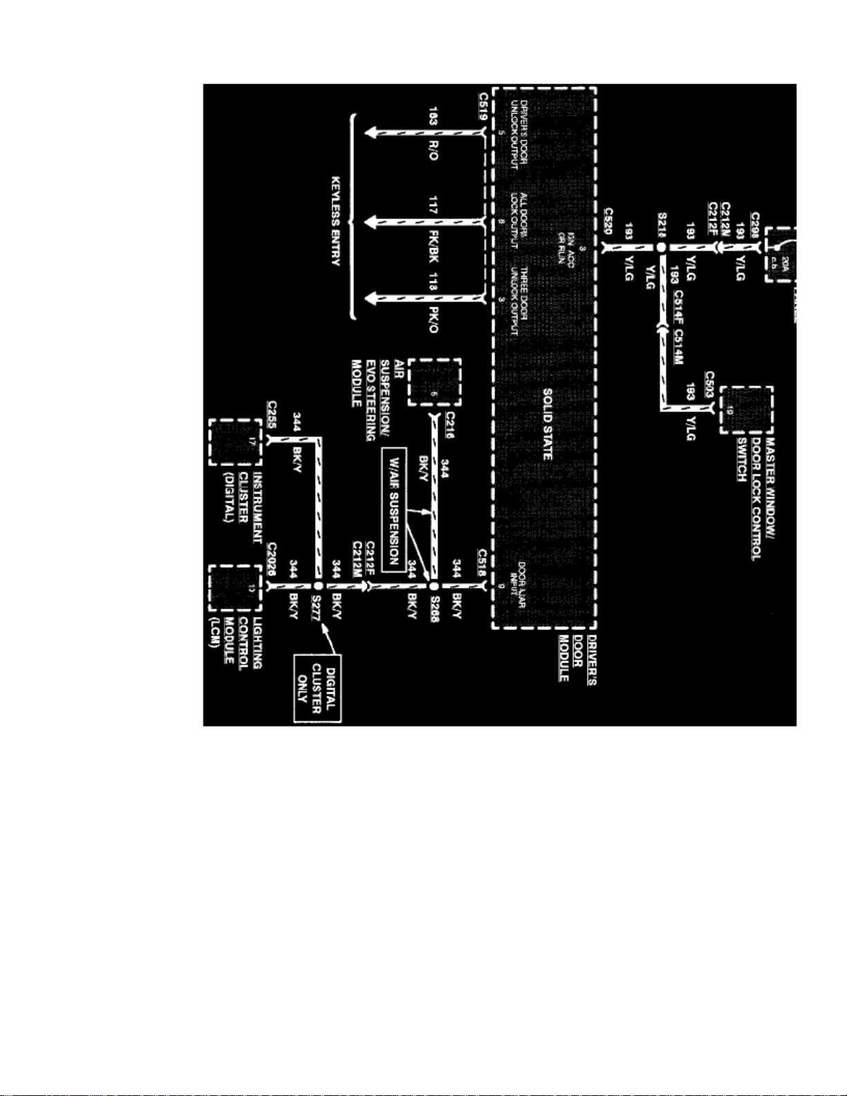
Driver's Door Module (Part 3 Of 3)
Page 75

Page 76
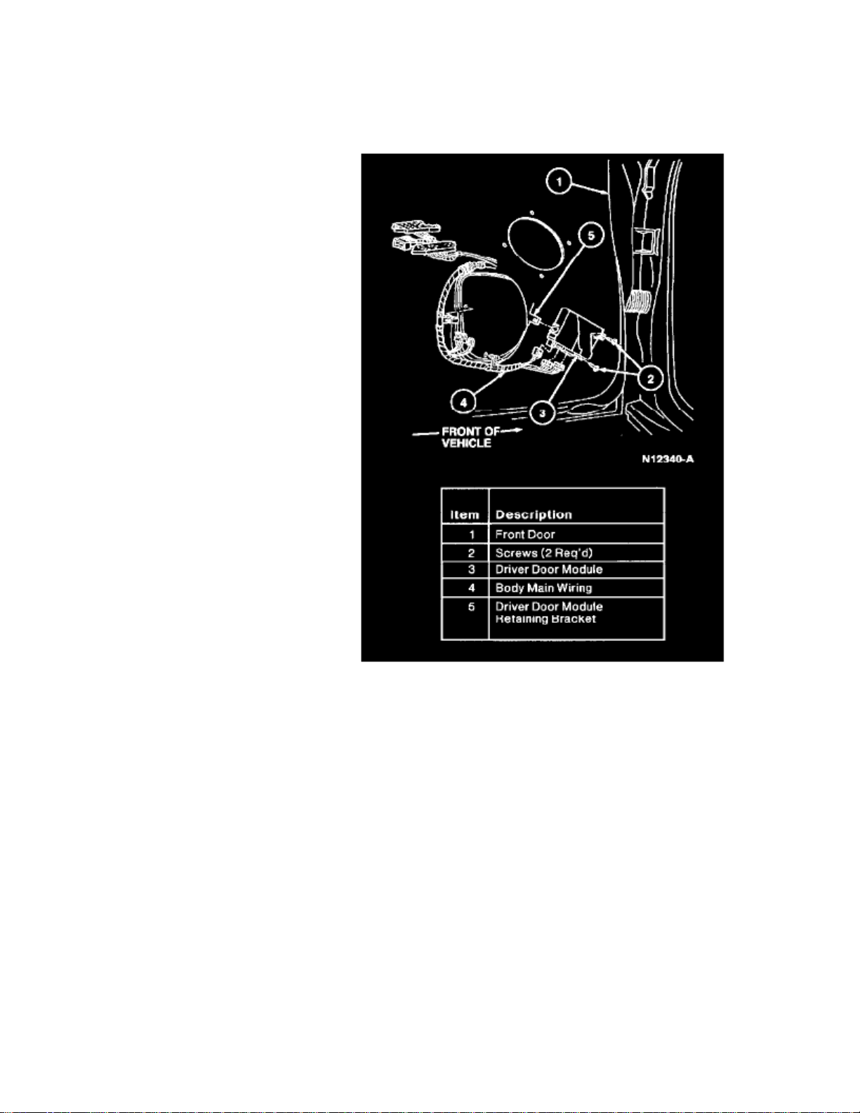
> Relays and Modules > Relays and Modules - Body and Frame > Power Seat Control Module > Component Information > Locations > Driver's Door Module
Power Seat Control Module: LocationsDriver's Door Module
The Driver's Door Module is located in center of the LH front door.
Page 77

Page 78
> Relays and Modules > Relays and Modules - Body and Frame > Power Seat Control Module > Component Information > Locations > Driver's Door Module > Page 62
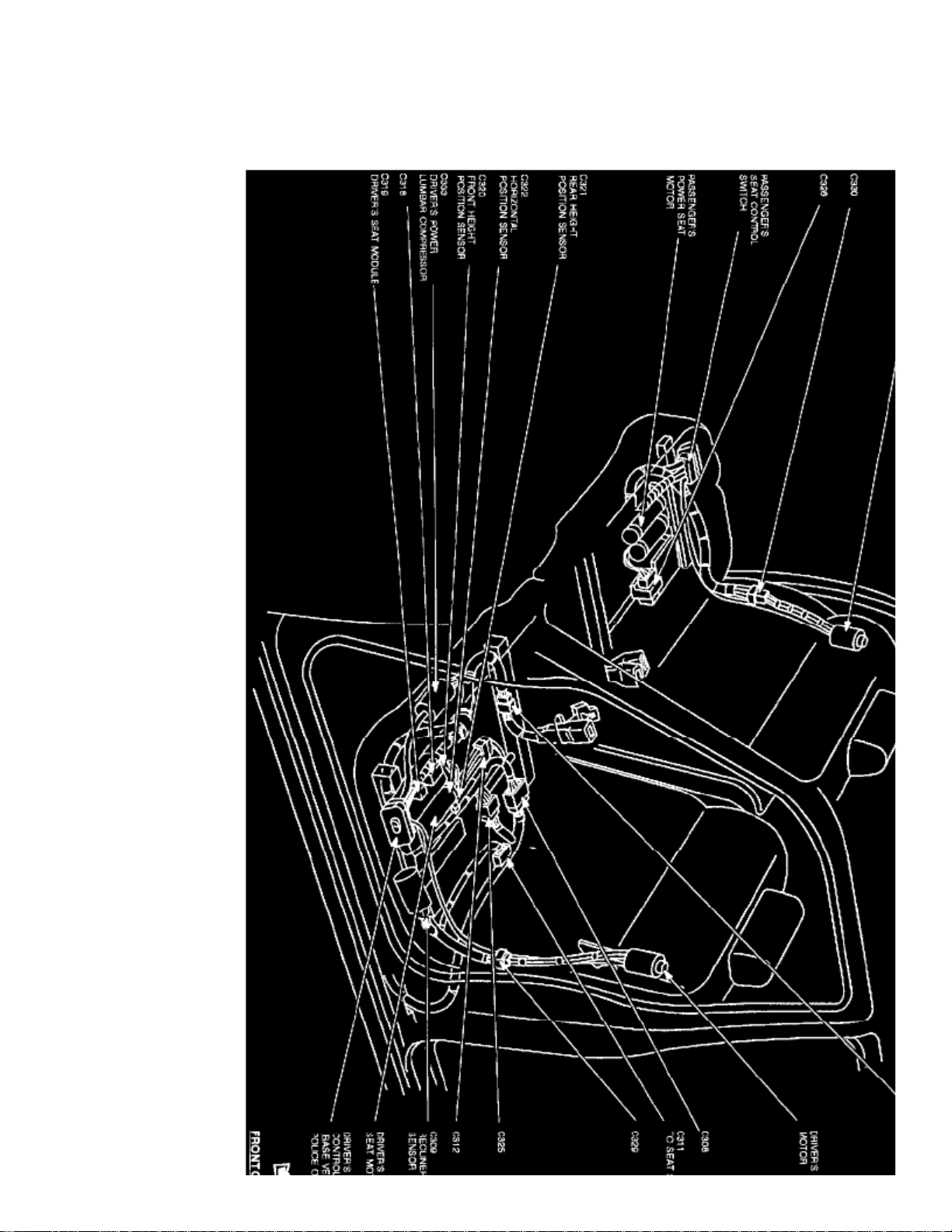
Power Seat Control Module: LocationsDriver's Seat Module
Page 79

Front Seat Assemblies
The Driver's Seat Module is located below the driver's seat.
Page 80
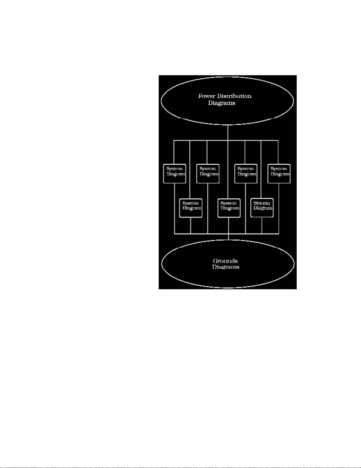
> Relays and Modules > Relays and Modules - Body and Frame > Power Seat Control Module > Component Information > Diagrams > Diagram Information and Instructions
Power Seat Control Module: Diagram Information and Instructions
How to Find and Use These Diagrams
Diagrams are presented in three main categories:
- Power Distribution Diagrams
- System Diagrams
- Grounds Diagrams
Page 81

> Relays and Modules > Relays and Modules - Body and Frame > Power Seat Control Module > Component Information > Diagrams > Diagram Information and Instructions
> Page 65
Crown Victoria V8-281 4.6L SFI (1998)
Page 82
Page 83

> Relays and Modules > Relays and Modules - Body and Frame > Power Seat Control Module > Component Information > Diagrams > Diagram Information and Instructions
> Page 66
Crown Victoria V8-281 4.6L SFI (1998)
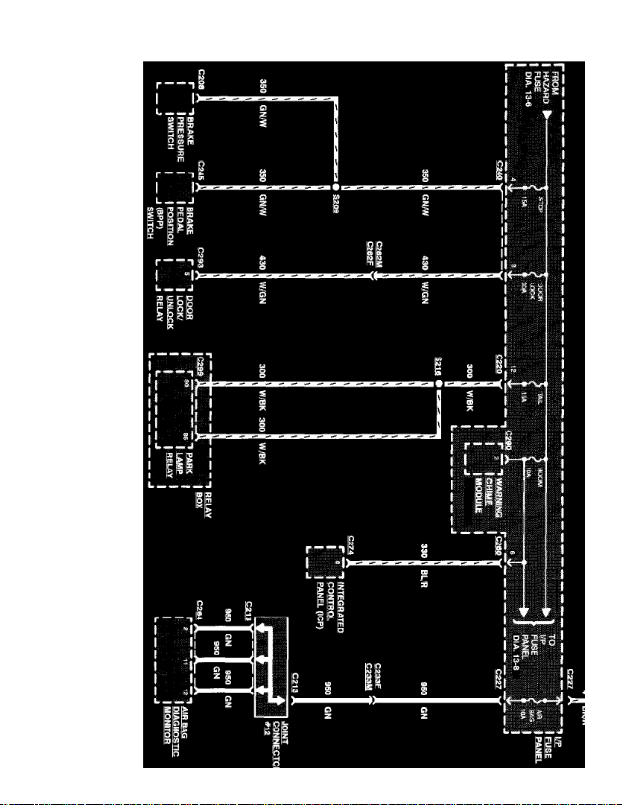
Sample Power Distribution Diagram
Power Distribution Diagrams
Provide the circuit details of how the system diagrams are powered. The power distribution source is shown at the top of a diagram page. All wires,connectors, and splices are shown in the same manner that the current flows, ending at the component/system being powered near the bottom of adiagram page. Circuits that go from one diagram page to another will be marked with large arrow heads.
The power distribution diagrams can be found at Starting and Charging/Power and Ground Distribution.
Page 84
Page 85

> Relays and Modules > Relays and Modules - Body and Frame > Power Seat Control Module > Component Information > Diagrams > Diagram Information and Instructions
> Page 67
Crown Victoria V8-281 4.6L SFI (1998)
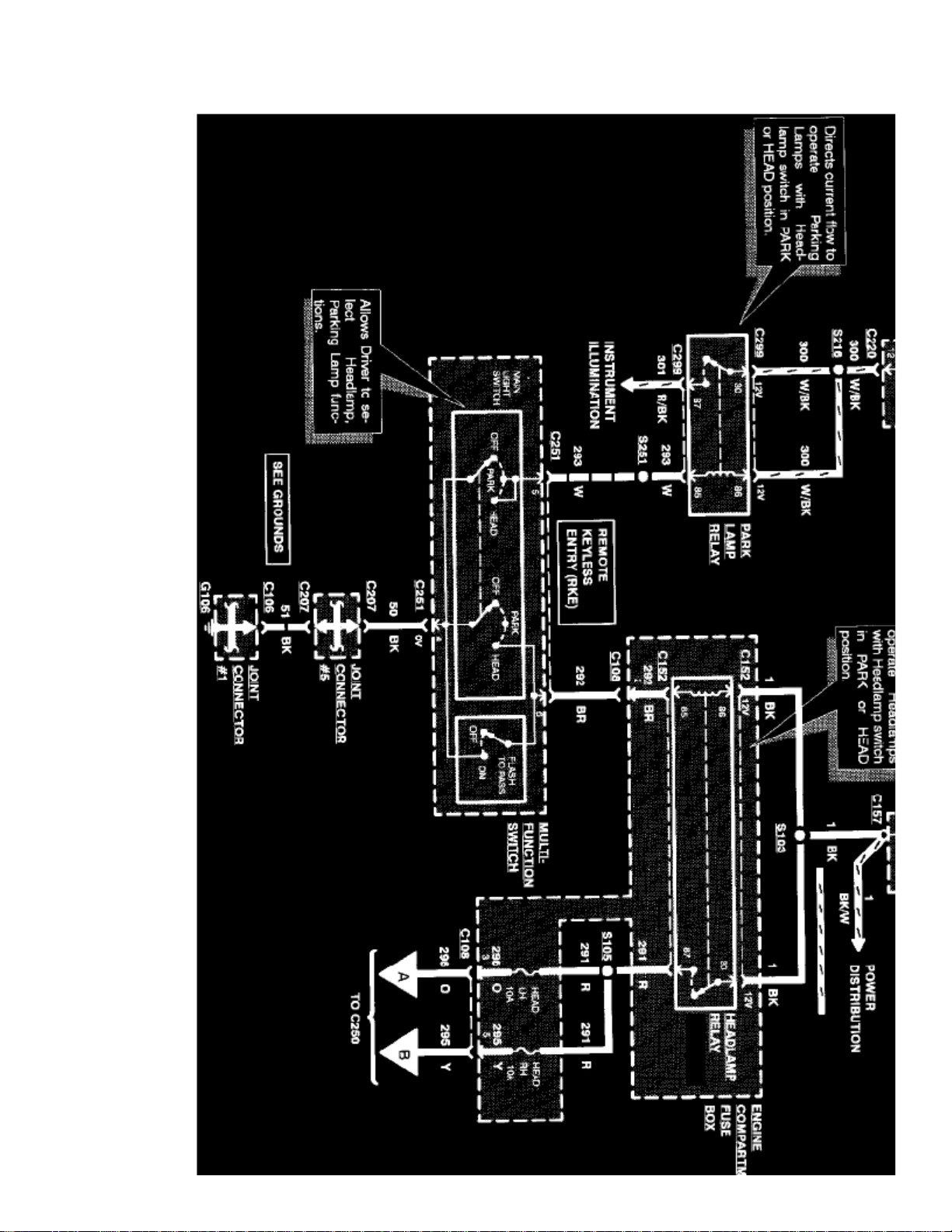
Sample System Diagram
System Diagrams
Components that work together are shown together in a system/subsystem diagram or set of diagrams. The system feed (circuit breaker, fuse, etc.) isshown at the top of a diagram page. All wires, connectors, components, and splices are shown in the same manner that the current flows, ending at theground at the bottom of a diagram page. Circuits that go from one diagram page to another will be marked with large arrow heads.
Page 86
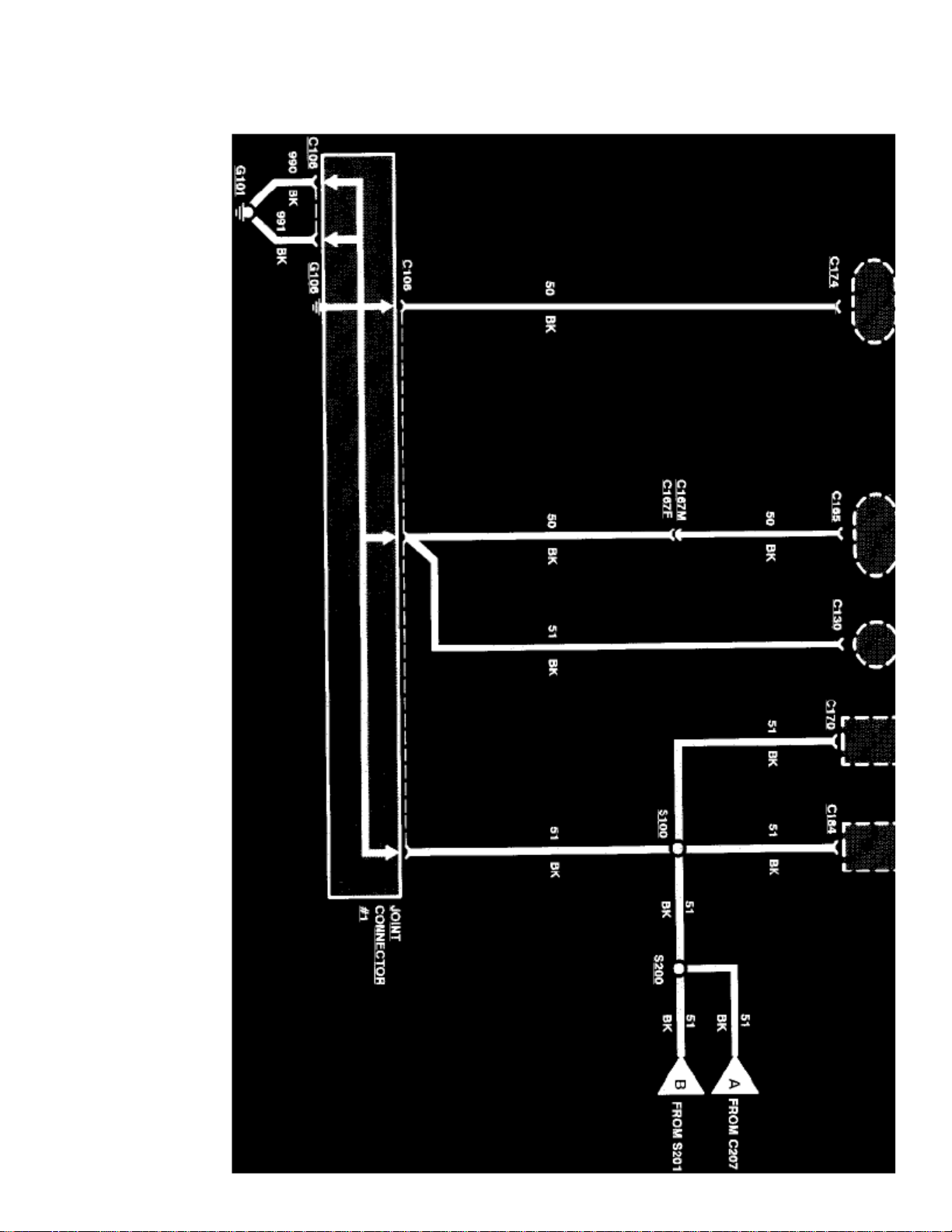
Management, Radio/Stereo, etc.
Page 87

> Relays and Modules > Relays and Modules - Body and Frame > Power Seat Control Module > Component Information > Diagrams > Diagram Information and Instructions
> Page 68
Crown Victoria V8-281 4.6L SFI (1998)
Sample Grounds Diagram
Grounds Diagrams
Provide the circuit details of how the system diagrams are grounded. This information is useful for checking interconnections of the grounding circuitsof different systems. The components/systems being grounded are shown at the top of a diagram page. All wires, connectors, and splices are shown in thesame manner that the current flows, ending at the ground at the bottom of a diagram page. Circuits that go from one diagram page to another will bemarked with large arrow heads.
The grounds diagrams can be found at Starting and Charging/Power and Ground Distribution.
Symbol Identification
Page 88
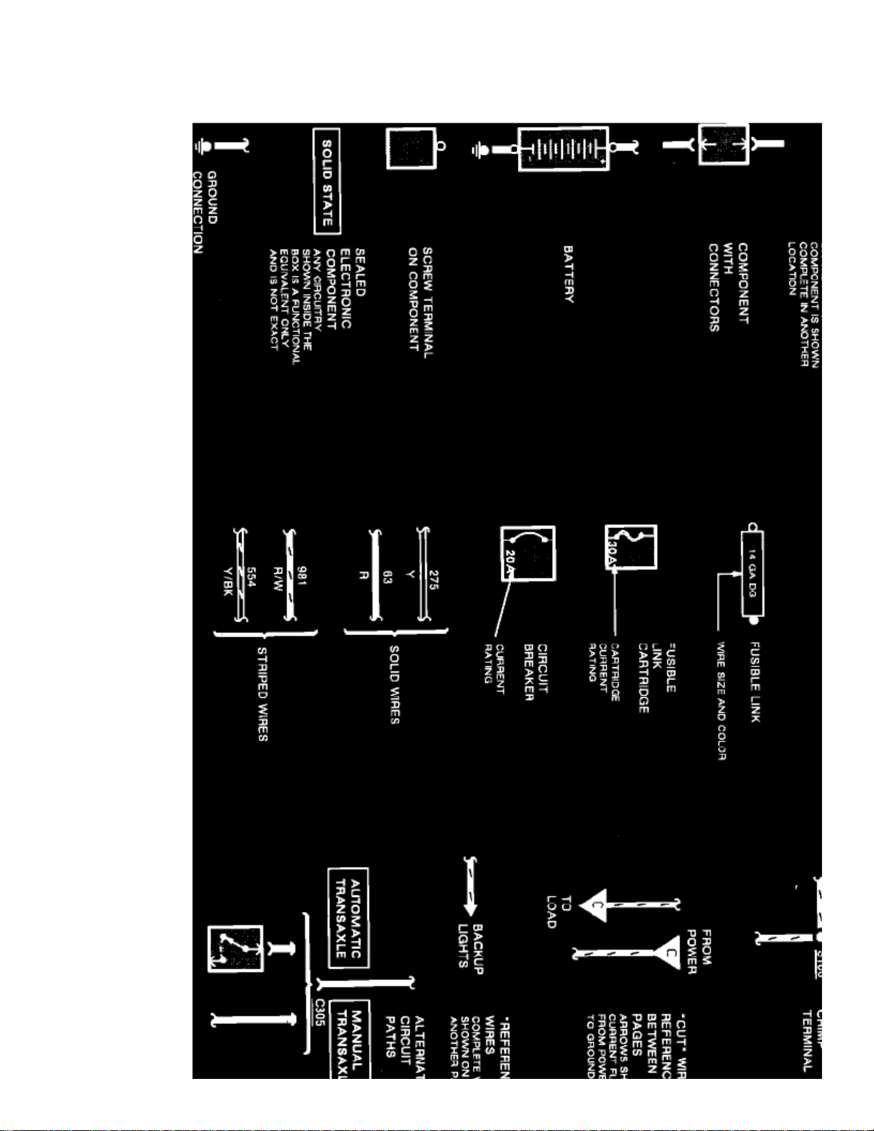
ELECTRICAL SYMBOLS
Page 89

> Relays and Modules > Relays and Modules - Body and Frame > Power Seat Control Module > Component Information > Diagrams > Diagram Information and Instructions
> Page 69
Crown Victoria V8-281 4.6L SFI (1998)
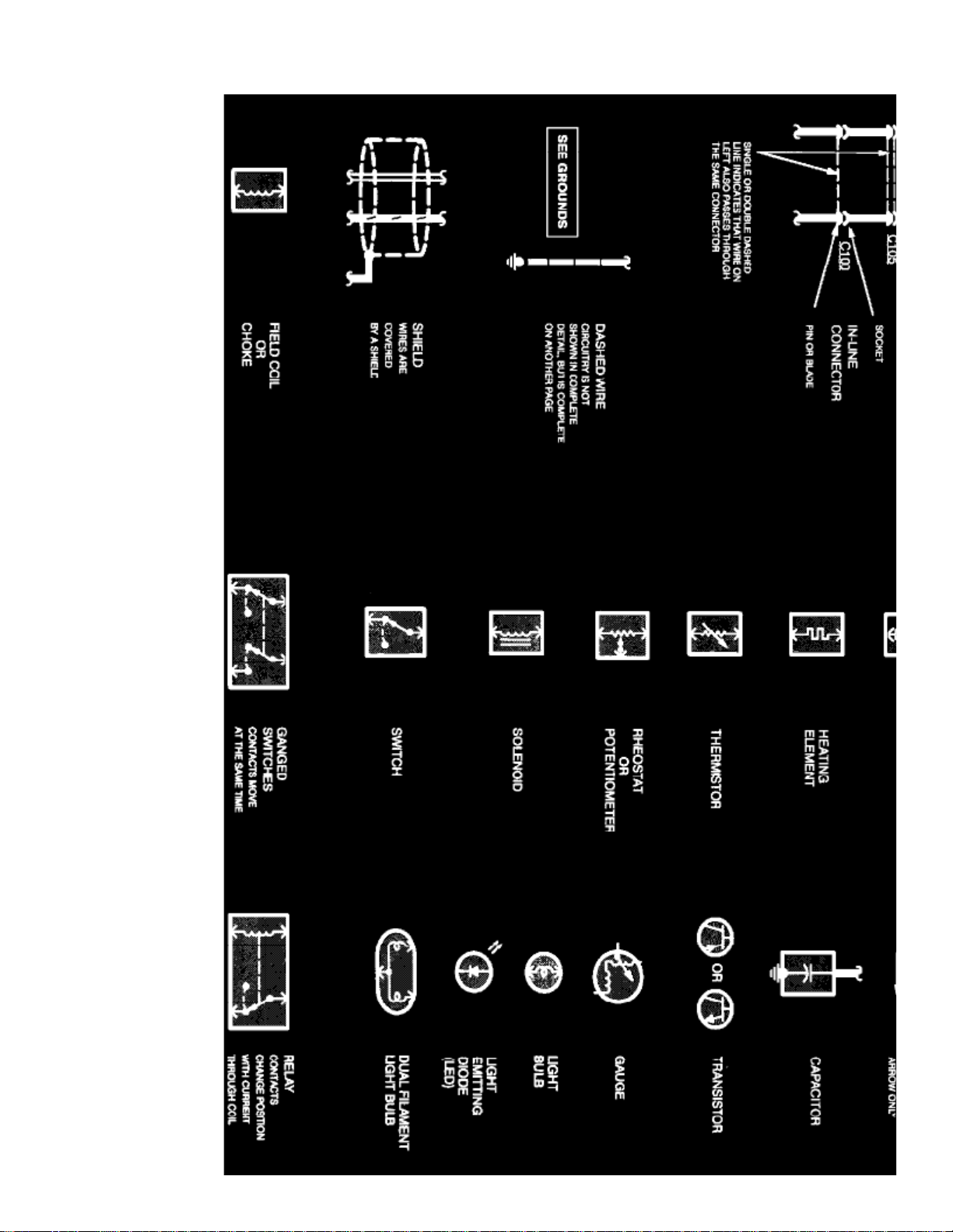
Electrical Symbols
Page 90
Page 91

> Relays and Modules > Relays and Modules - Body and Frame > Power Seat Control Module > Component Information > Diagrams > Diagram Information and Instructions
> Page 70
Crown Victoria V8-281 4.6L SFI (1998)
Electrical Symbols
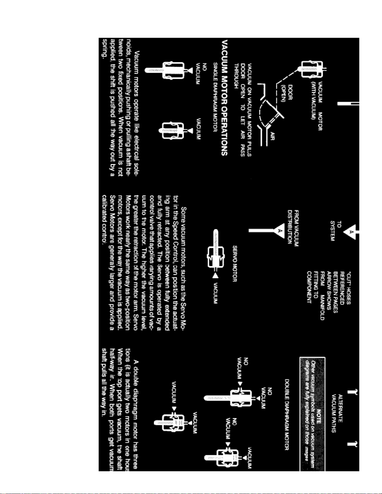
VACUUM SYMBOLS
Page 92
Page 93

> Relays and Modules > Relays and Modules - Body and Frame > Power Seat Control Module > Component Information > Diagrams > Diagram Information and Instructions
> Page 71
Crown Victoria V8-281 4.6L SFI (1998)
Vacuum Symbols
Wire Color Code Identification
BK
BL
BR
: Black: Blue: Brown: Dark BlueDB
Page 94

DG
GY
GN
LB
LG
PK
O
P
R
T
V
W
: Dark Green: Gray: Green: Light Blue: Light Green: Pink: Orange: Purple: Red: Tan: Violet: White: YellowY
NOTE:
Whenever a wire is labeled with two colors, the first color listed is the basic color of the wire, and the second color listed is the stripe marking ofthe wire.
Page 95

Page 96
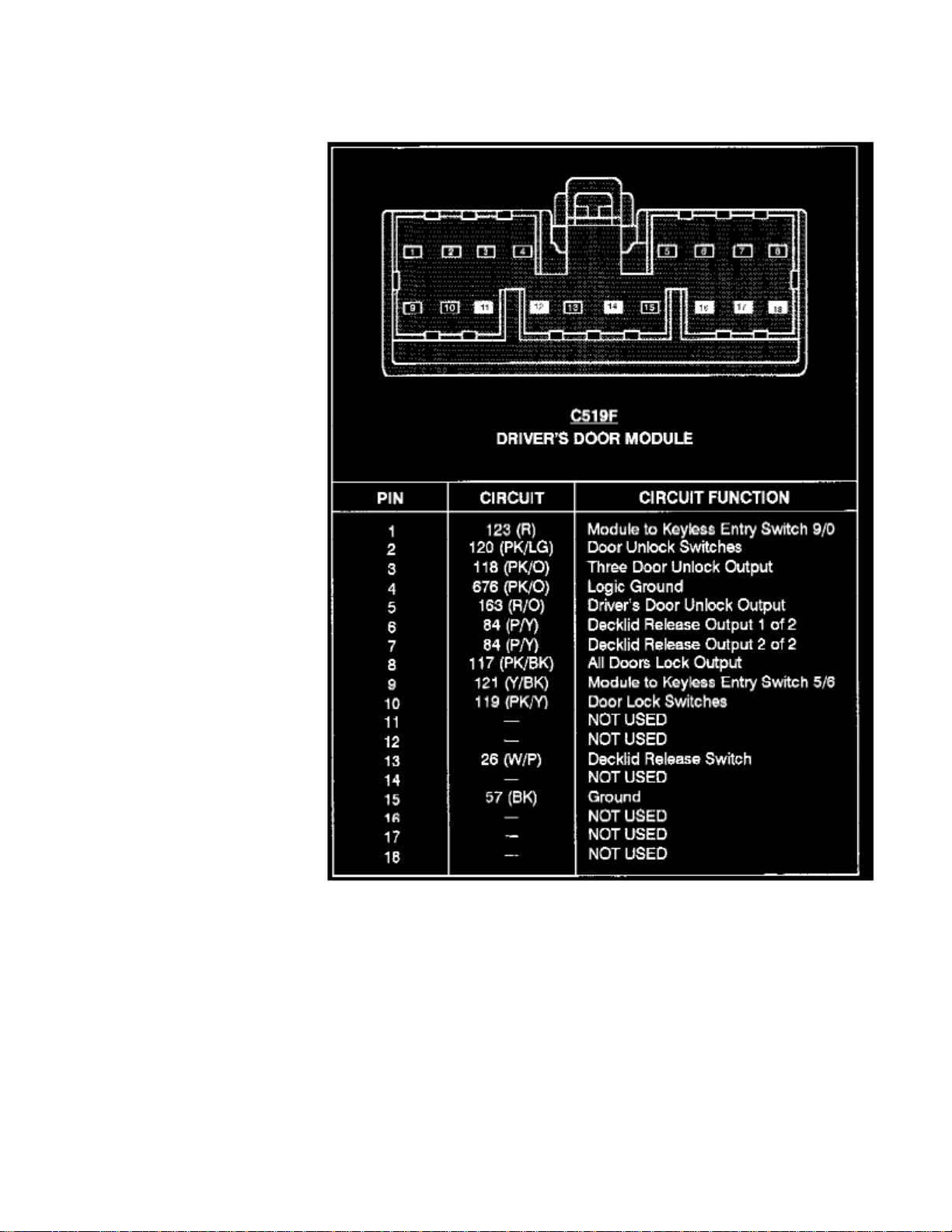
> Relays and Modules > Relays and Modules - Body and Frame > Power Seat Control Module > Component Information > Diagrams > Diagram Information and Instructions > Page 72
Power Seat Control Module: Connector Views
Driver's Door Module (C519)
Page 97

> Relays and Modules > Relays and Modules - Body and Frame > Power Seat Control Module > Component Information > Diagrams > Diagram Information and Instructions
> Page 73
Crown Victoria V8-281 4.6L SFI (1998)
Page 98
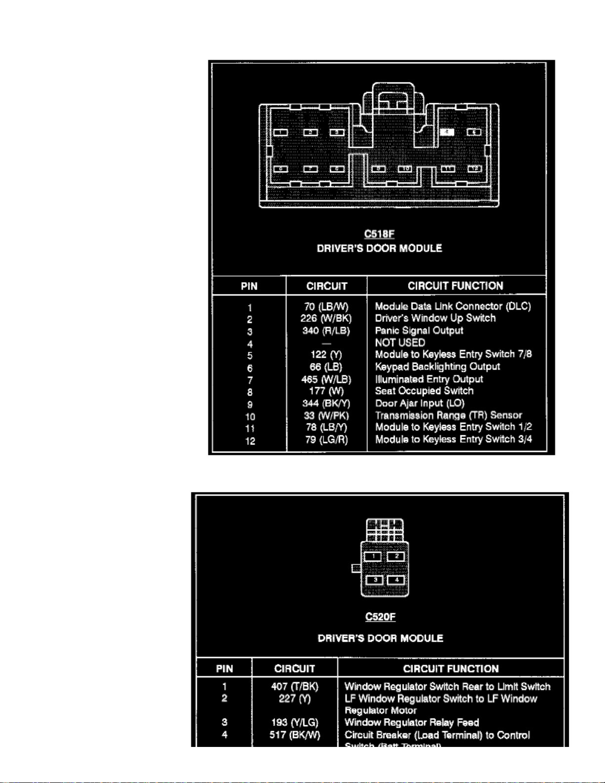
Driver's Door Module (C518)
Page 99

Driver's Door Module (C520)
Page 100
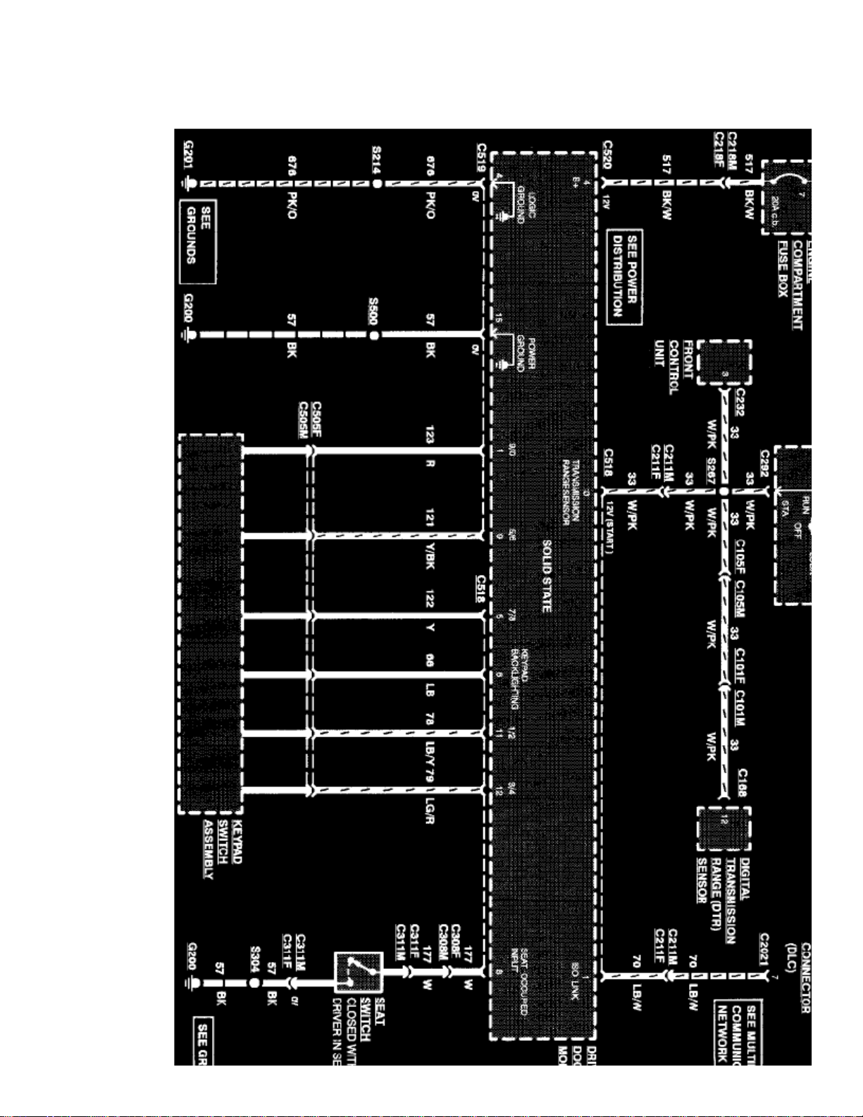
> Relays and Modules > Relays and Modules - Body and Frame > Power Seat Control Module > Component Information > Diagrams > Diagram Information and Instructions > Page 74
Power Seat Control Module: Electrical Diagrams
 Loading...