

Ford 2n series, 8n series, 9n series Shop Manual

I&T Shop Service
Ford Shop Manual
Series 2N 8N 9N
Manual NO. FO-4
copyright 1953 - EXPIRED
This book free to print, share, distribute with anyone!
Remastered Version 1.2

FO-4 I&T (Remastered Ver.1.2 ) 05-24-2015
Connect/Report Errors – jcchapster@gmail.com

FO-4 I&T (Remastered Ver.1.2 ) 05-24-2015
PREFACE
This book was transcribed, reformatted to this PDF version by me, John
Chapman.
I'd be delighted for you to connect with me at any or all of:
Email: j cchapster@gmail.com
Twitter: http://twitter.com/jcchapster
Linked-In: https://www.linkedin.com/in/jcchapster
Facebook: https://www.facebook.com/thejcchapster
TRACTOR MANUAL ARCHIVE
I'm building a Tractor Manual Archive. The Tractor Manual Archive is a
repository of Tractor Manuals that are typically out of Copyright, and
are now in Public Domain. Additionally, manuals that have Copyright
holder permission to be included will be archived as well.
Do you have an old manual? It might be a manual others are looking for.
Contact the Tractor Manual Archive about how to share your manual with
others, and be a part of preserving useful history.
Do you have a PDF of an old manual? Even if purchased, if it is out of
copyright it can be shared.–
Email me to learn more, to participate, to download manuals as they
become available.
ERRORS and OMMISSIONS If you discover an error with this manual, –
please email: jcchapster@gmail.com and I will correct and release an
updated version.
- John Chapman / Tractor Manual Archive administrator
Connect/Report Errors – jcchapster@gmail.com

Change log
5-23-2015 Corrected some images placements and typos. Moved to –
version 1.1.
5-24-2015 Corrected some other minor issues. Moved to version –
1.2.
FO-4 I&T (Remastered Ver.1.2 ) 05-24-2015
Connect/Report Errors – jcchapster@gmail.com

FO-4 I&T (Remastered Ver.1.2 ) 05-24-2015
SHOP MANUAL
FORD
Models:
8N - 8NAN
2N - 2NAN - 9N - 9NAN (Ford - Ferguson)
Serial number is stamped on left side of engine block.
Beginning Tractor Serial Numbers
Models 9N - 9NAN Models 2N - 2NAN Models 8N - 8NAN
1942 99047 1947 1
1943 105412 1948 37908
1939 1 1944 126575 1949 141370
1940 10276 1945 170018 1950 245637
1941 46018 1946 198767 1951 343593
1942 88934 1947 258540 1952 442035
Connect/Report Errors – jcchapster@gmail.com

FO-4 I&T (Remastered Ver.1.2 ) 05-24-2015
Connect/Report Errors – jcchapster@gmail.com

FO-4 I&T (Remastered Ver.1.2 ) 05-24-2015
INDEX
(By Starting Paragraph)
MODELS 2N-9N 8N
BELT PULLEY 97,97A 97,97A FINAL DRIVE
Bevel Gears 86,87 86,87
BRAKES Differential Overhaul 85 85
Adjustment 91 92 Differential R&R 84 84
R&R and Overhaul 93 94
CARBURETOR 42 42
CLUTCH Wheel Axle Shaft R&R 89 90
Overhaul 64A 66
Pedal Adjustment 63 63 FRONT SYSTEM
Remove & Reinstall 64,64A 65,66 Axle Main Member 1 1
COOLING SYSTEM Steering Gear Adjust 6 7,12
Pump R&R 46 46 Steering Gear Overhaul 6B 11,14
Pump Overhaul 47 48 Steering Gear R&R 6A 11
Thermostat 49 49 Steering Spindles 2 2
DIFFERENTIAL GOVERNOR
Overhaul 85 85 Adjustment 44 44
Wheel Axle Shaft
Bearings Adjust 88,88A 88,88A
Wheel Axle Shaft
Bearings Renew 89 90
Axle Pivot Pin & Bushing 3 3
Remove & Reinstall 84 84 Overhaul 45 45
ELECTRICAL HYDRAULIC SYSTEM
Ignition 54-61 54-58 Adjustment 99 101
Generator 50 50 Lift Cover 105 109
Generator Regulator 51,52 51,52 Pump Overhaul 124 116
Connect/Report Errors – jcchapster@gmail.com

FO-4 I&T (Remastered Ver.1.2 ) 05-24-2015
MODELS 2N-9N 8N
Starting Motor & Switch 53 53 Pump R&R 115 115
Pump Test 114 114
ENGINE Trouble Shooting 112 112
Assembly R&R 20 20 Work Cylinder 106 106
Cam Followers 26 26
Camshaft 29 29 IGNITION SYSTEM
Connecting Rods & Brgs 36 36 Battery Ignition 54-57 54-60
Crankshaft & Bearings 37 37 Magneto Ignition 61-62A - - -
Crankshaft Oil Seals 38 38
Cylinder Head 21 21 POWER TAKE-OFF 95,96 95,96
Cylinder Sleeves 32-33 32-33
Flywheel R&R 39 39 REAR AXLE
Flywheel Timing Marks 39A 39A Bearing, Renewal 89 90
Front Oil Seal 38 38 Seals, Renewal 89 90
Ignition Timing 55-62 55-59 Shaft, R&R 89 90
Main Bearings 37 37
Oil Pan 40 40 STEERING GEAR
Oil Pump 41 41 Adjustment 6 ,12
Pistons 32 32 Overhaul 6B 11,14
Piston Pins 35 35 Remove & Reinstall 6A 11
Piston & Rod Removal 30 30 TRANSMISSION
Piston Rings 31 32 Assembly R&R 70,70A 70,70A
Rear Oil Seal 38 38 Bevel Pinion 86 86
Tappets 26 26 Clutch Shaft 74 79
Timing Gear Cover 28 28 Countershaft 75 80
Timing Gears 28A 28A Main Drive Gear & Shaft 74 79
Valves 22,22A 22,22A Mainshaft 72 78
Valve Guides 25 25 Reverse Gear 76 81
Valve Push Rods 26 26 Shifter Rails and Forks 71 77
Valve Rotators 23,27 26,27
Connect/Report Errors – jcchapster@gmail.com

FO-4 I&T (Remastered Ver.1.2 ) 05-24-2015
MODELS 2N-9N 8N
Valve Seats 24 24
Valve Springs 25 25
Valve Timing 28A 28A
Connect/Report Errors – jcchapster@gmail.com

FO-4 I&T (Remastered Ver.1.2 ) 05-24-2015
Connect/Report Errors – jcchapster@gmail.com

FO-4 I&T (Remastered Ver.1.2 ) 05-24-2015
CONDENSED SERVICE DATA
Tractor Models 2N, 8N, 9N
GENERAL
Engine Make Own
Engine Type L Head
Cylinders 4
Bore-Inches 3-3/16
Stroke-Inches 3-3/4
Displacement-Cubic Inches 119.7
Compression Ratio-Kerosene 4.75
Compression Ratio-Gasoline:
2N-9N-Early 8N 6.1
Later 8N 6.7
Pistons Removed From: Above
Main Bearings, Number of 3
Main Bearings, Adjustable? No
Rod Bearings, Adjustable? No
Cylinder Sleeves, Dry, Wet Dry
Production Cylinder Sleeves-Material (8N Prior 433578 2N - 8N)– Steel
Production Cylinder Sleeves-Material (8N After 433577) Iron
Service Cylinder Sleeves-Material Iron
Forward Speeds (2N-9N) 3
Forward Speeds (8N) 4
Generator-Make Own
Starter-Make Own
TUNE-UP
Firing Order 1-2-4-3
Valve Tappet Gap-Inlet 10-12C
Valve Tappet Gap-Exhaust 14-16C
Connect/Report Errors – jcchapster@gmail.com

FO-4 I&T (Remastered Ver.1.2 ) 05-24-2015
Exhaust Tappet Gap-Fitted With Rotators 14-16C
Valve Face Angle-Degrees 45
Valve Seat Angle-Degrees 45
Ignition Distributor Make Own
Distributor Model (8N Prior 263844 - 2N - 9N) 9N12100
Distributor Model (8N After 263843) 8N12127
Breaker Gap (Angle Mounted Distributor 8N12127) 0.025
Retarded Timing (8N Prior 263844 - 2N - 9N) TC
Retarded Timing (8N After 263843) 4°B
Advanced Timing (8N Prior 263844 - 2N - 9N) 25°B
Advanced Timing (8N After 263843) 17°B
Flywheel Timing Mark Indicating:
Retarded Timing (8N Prior 263844 - 2N - 9N) None
Retarded Timing (8N After 263843) 4° line
Advanced Timing (8N Prior 263844 - 2N - 9N) None
Advanced Timing (8N After 263843) 17° line
Distributor Governor Advance Curve Para: 54, 58
Spark Plug Make Champion
Spark Plug Model for Gasoline H10
Carburetor Make, Marvel-Schebler yes
Carburetor Model Paragraph: 42
Carburetor Float Setting-Inches 9/32
Engine Low Idle RPM 400
Engine High Idle RPM 2200
Belt Pulley RPM @ 2000 Engine RPM 1358
PTO RPM @ 1500 Engine RPM 545
SIZES-CAPACITIES-CLEARANCES
(Clearances in Thousandths)
Crankshaft Journal Diameter 2.248-2.249
Crankpin Diameter 2.094
Camshaft Journal Diameter 1.797
Piston Pin Diameter .7501-.7504
Connect/Report Errors – jcchapster@gmail.com

FO-4 I&T (Remastered Ver.1.2 ) 05-24-2015
Valve Stem Diameter (One-Piece Valve Guide) .341-.342
Valve Stem Diameter (Two-Piece Valve Guide) .3105-.3115
Cam Follower (Push Rod) Diameter-Inches .9995
Compression Ring Width-Inches .093
Oil Ring Width-Inches .187
Main Bearings Running Clearance 1-3
Rod Bearings Running Clearance 1-3.5
Piston Skirt Clearance (Steel Pistons) 2.5-4.0
Piston Skirt Clearance (Aluminum Pistons) 1.5-2.5
Camshaft Bearing Clearance 1-2
Cam Follower (Pushrod) Running Clearance .4-1
Crankshaft End Play 2-6
Cooling Systems-Gallons 3
Crankcase Oil-Quarts 6
Transmission, Differential & Hydraulic System-Quarts 20
Belt Pulley Housing-Quarts 1/3
Connect/Report Errors – jcchapster@gmail.com
FO-4 I&T (Remastered Ver.1.2 ) 05-24-2015
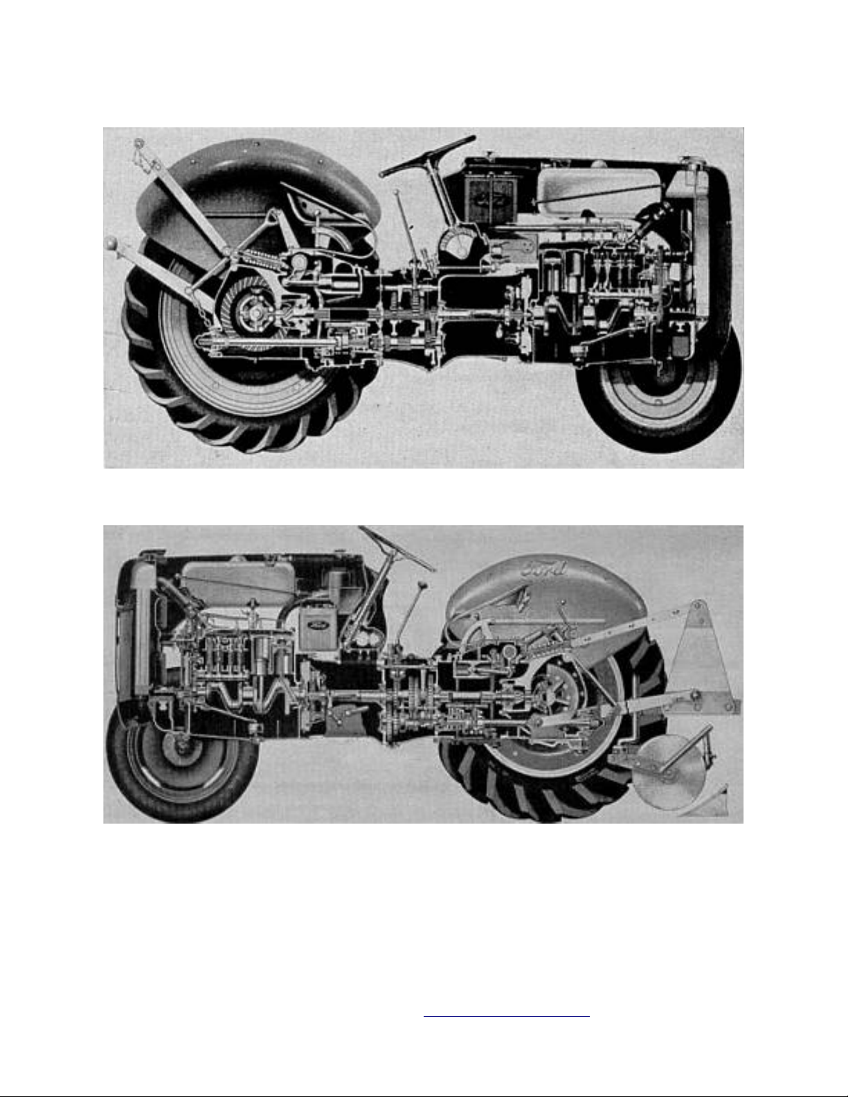
Models 2N and 9N
MODEL 8N
Connect/Report Errors – jcchapster@gmail.com
FO-4 I&T (Remastered Ver.1.2 ) 05-24-2015
Fig. FO1 - Front axle as used on model 8N.
Note hole spacing of tread adjusting bolts.
Fig. FO2 - Front axle on models 2N and 9N.
reinstallation of axle parts removed. See Fig.
FO3.
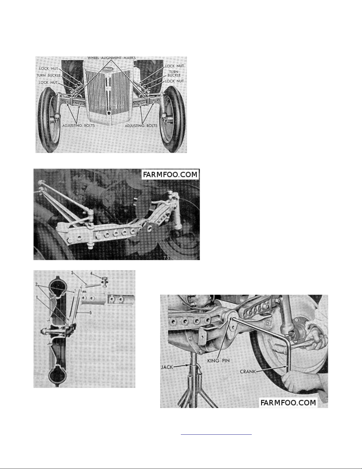
FRONT AXLE
1. The front axle is
constructed in three sections
and may be adjusted to vary
tread width. See Figs. FO1 and
FO2. Steering linkage must be
readjusted on model 8N when
tread width is changed. Model
2N - 9N wheel alignment is not
affected by tread width
adjustment.
SPINDLE BUSHINGS
2. To rebush axle spindles,
first block up tractor front
end and remove steering arms.
Slide spindles with wheels
attached, out of axle ends.
Drive old bushings out of axle
and install new bushings, using
a piloted installing tool. New
steel bushings are presized and
are not reamed. Check and
adjust wheel alignment, after
Fig. FO3 - Front axle hub
and spindle on models
2N-8N-9N.
Connect/Report Errors – jcchapster@gmail.com
Fig. FO4 - Method of removing axle center pin.

FO-4 I&T (Remastered Ver.1.2 ) 05-24-2015
AXLE PIN BUSHINGS
3. Remove front hood bolts at bottom and block up under hood. Hold up front end of
engine with jack under oil pan and unbolt axle support. Remove two bottom radiator
bolts and raise engine and radiator high enough to permit removal of axle center
pin. Remove pin, using hand crank as show in Fig. FO4.
Connect/Report Errors – jcchapster@gmail.com
FO-4 I&T (Remastered Ver.1.2 ) 05-24-2015
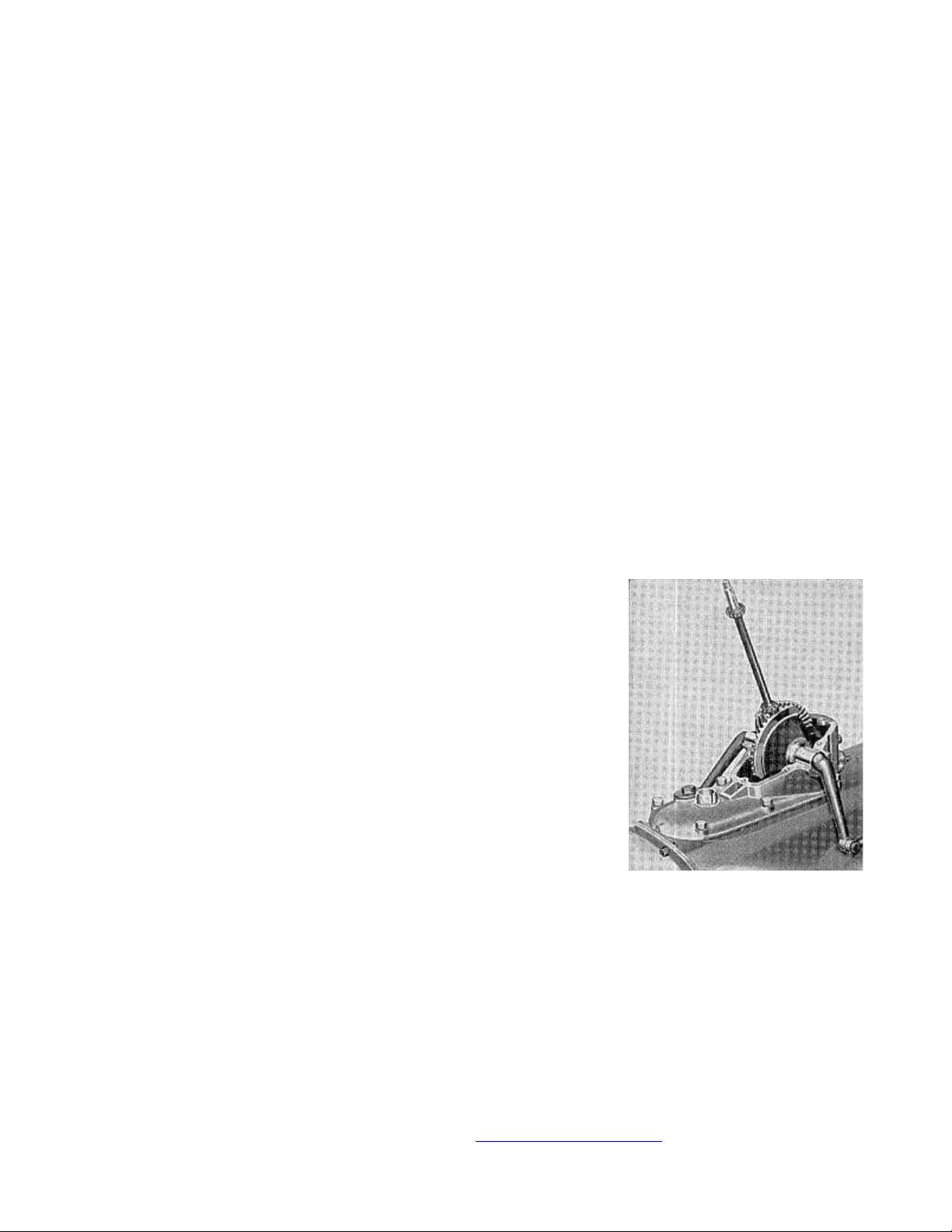
STEERING SYSTEM
The steering gear on models 2N-9N consists of two sector gears and integral arm
units, both meshed with a steering shaft and pinion assembly. Gear units are
mounted in a housing Fig. FO5, which also serves as a transmission case cover. The
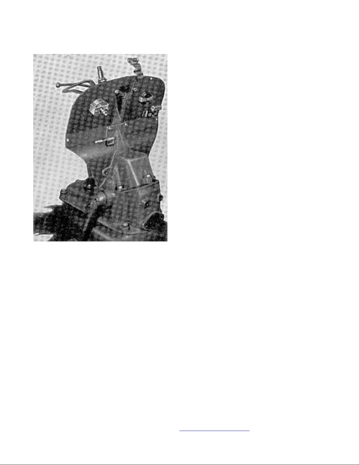
gear housing is constructed in two parts and also supports the instrument panel
Fig. FO6.
The steering gear used on model 8N tractor is a Saginaw screw and recirculating
ball nut type, mounted on top of transmission housing.
ADJUSTMENT & OVERHAUL
Models 2N 9N –
6. ADJUSTMENT. The steering shaft bearing may be adjusted without removing gear
unit from tractor. To adjust steering shaft bearings, remove steering wheel and
shaft bearing dust cover (19 Fig. FO7). Remove locknut–
and lock washer (1). Adjust lower nut until end play is
removed and shaft still turns freely. Install lock washer
and locknut and tighten nut.
Detach drag links from sector arms and check backlash at
arms while steering wheel is held stationary. If
excessive sector gear backlash or end play exists, it
will be necessary to remove upper gear housing (11) to
gain access to sectors for adjustment.
6A. To clear upper housing for removal, it will be
necessary to remove hood, battery and instrument panel.
When housing is off, invert same in a vise and place both
sectors (15 & 26) in position, meshed with steering shaft
pinion (14). Check gear mesh and backlash with sectors
held in normal operating position. Thrust washers (25 &
27) which are available in three sizes; thick, medium and
thin, should be installed according to requirements, for minimum sector end play
and backlash. Reinstall assembly after adjustment is complete and synchronize
gears.
Fig. FO5 Models 2N-9N –
steering gear with upper
housing removed.
Connect/Report Errors – jcchapster@gmail.com
FO-4 I&T (Remastered Ver.1.2 ) 05-24-2015
When early model 9N steering gear is
turned to either extreme, severe steering
conditions may cause sectors to jump out
of mesh and result in an uneven turning
radius. To synchronize sectors without
removing steering housing, disconnect both
drag links at steering arms an move left
arm rearward as far as possible, and right
arm in opposite direction to un-mesh
gears. Re-engage both sectors with
steering shaft pinion and check
synchronism by observing whether steering
arms are parallel and point slightly
rearward, when gear is in mid or straight
ahead position. Reconnect drag links and
adjust same if necessary.
6B. OVERHAUL. To completely overhaul the
steering gear it is necessary to first
remove the unit as per paragraph 6A. Renew
worn parts and install new oil seals.
Model 8N Prior to 216989
Fig. FO6 Models 2N-9N steering gear–
unit with attached instrument panel.
nut. Refer to Fig. FO8. The right sector meshes with the left sector and rotates in
the opposite direction. On tractors after serial 216988 the arrangement is reversed
as shown in Fig. FO12A, the right sector being meshed with the ball nut, and
because the sector teeth are of the bevel type a different method of backlash
adjustment is employed.
On tractors prior to serial 216989 the
sector teeth are straight cut and the left
sector (viewed from rear of tractor)
meshes with the rack teeth on the ball
Connect/Report Errors – jcchapster@gmail.com
FO-4 I&T (Remastered Ver.1.2 ) 05-24-2015
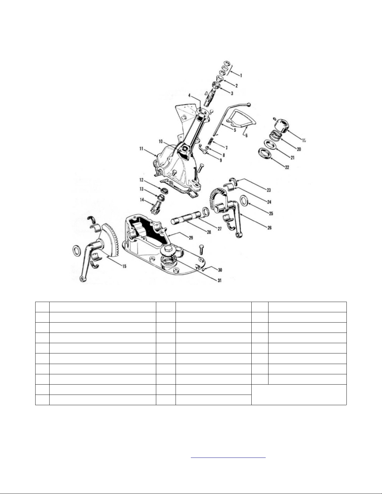
Fig. FO7 - Steering gear on models 2N-9N.
1. Steering post nuts and lock 11. Upper gear housing 24. Sector bearing
2. Bearing cone 12. Lower post bearing 25. Outer thrust washer
3. Upper post bearing 13. Bearing cone 26. Right sector
4. Bearing cup 14. Shaft and pinion 27. Inner thrust washer
5. Throttle control rod 15. Left sector 28. Sector shaft
6. Quadrant 19. Cap 29. Lower gear housing
7. Spring 20. Spring 30. Expansion plug
8. Spring seat 21. Seal retainer 31. Filler plug
9. Control rod arm 22. Dust seal
10. Bearing cup 23. Packing
7. ADJUSTMENT. Before making any adjustments, disconnect both drag links at
sector shaft arms. Turn steering wheel until sector arms are parallel, and both
point slightly rearward. Grasp left sector arm and check gear backlash while
Connect/Report Errors – jcchapster@gmail.com
FO-4 I&T (Remastered Ver.1.2 ) 05-24-2015
steering wheel is held steady to prevent movement of worm. If any backlash is felt,
proceed as follows:
Fig. FO8 - Disassembled sector shafts of ball nut gear used on model 8N
tractors prior to serial 216989. Later type is shown in Fig. FO12.
8. SECTOR MESH ADJUSTMENT. Remove four cap screws from left (viewed from rear of
tractor) sector shaft cover Fig. FO8. Rotate cover and metal gasket counterclockwise (viewed from left side of tractor) as far as possible by hand and
reinstall cap screws in four matching holes. Recheck backlash and if none is
present, proceed to adjust right sector in a similar manner, rotating right sector
shaft cover clockwise to remove backlash instead of counter-clockwise. IF BOTH
SECTOR ARMS NOW HAVE ZERO BACKLASH, STEERING GEAR UNIT IS COMPLETELY ADJUSTED AND
WORM SHAFT END PLAY ADJUSTMENT OUTLINED IN PARAGRAPH 9 WILL NOT BE REQUIRED.
Adjustment is correct when pull required to rotate steering wheel through mid or
straight forward position is not less than 2-1/2 or more than 6 pounds with drag
links disconnected. Measure pull with a spring scale hooked to rim of steering
wheel and read scale when wheel is in motion. With adjustment of right sector
loosened, correct scale reading for worm shaft and left sector after adjustment is
2 to 3 pounds. When all of the backlash of LEFT sector can not be corrected by
foregoing adjustment, any remaining free motion is probably due to excessive worm
shaft bearing clearance. If that condition exists, rotate both sector housings
opposite the directions given for backlash adjustment, to relieve load on worm
shaft, and adjust worm shaft bearing clearance as outlined in next paragraph.
WORM SHAFT BEARING ADJUSTMENT. With both drag links disconnected from sector shaft
Connect/Report Errors – jcchapster@gmail.com
FO-4 I&T (Remastered Ver.1.2 ) 05-24-2015
arms, and with both sector adjustments loosened, check worm shaft bearing
adjustment by pulling up and pushing down on steering wheel. If looseness is
present, adjust bearings to a slight pre-load by removing a shim or shims from top
face of gear housing, after first removing steering gear cover and tube assembly
Fig. FO10. To clear gear assembly for removal, it will be necessary to remove hood,
battery and instrument panel.
Bearing adjustment is correct, when pull
required to rotate steering wheel through
center or straight forward position is 1-1/2
pounds with drag links disconnected and sector
mesh adjustments loosened. Measure pull with a
spring scale hooked to rim of wheel and take
the reading while wheel is in motion.
After completing worm shaft bearing adjustment,
readjust backlash of both sectors as outlined
in paragraphs 7 and 8.
11. OVERHAUL. Hood, battery and instrument
panel must be removed before steering gear unit
can be removed. After unit is cleared for
removal, disconnect both drag links at steering
gear arms, unbolt steering gear unit from
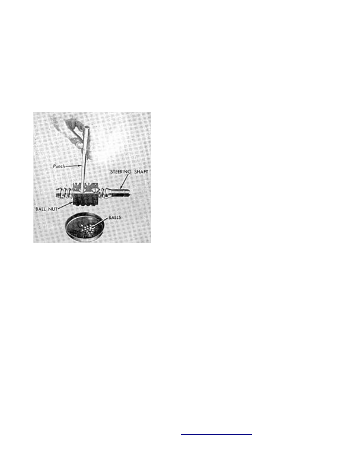
Fig. FO9 It is possible to –
disassemble the screw shaft and
ball nut assembly used in model
8N tractors but such procedure
is not recommended. Refer to
text.
gears and covers from sides of gear case Fig. FO8. To facilitate removal of –
these sub assemblies, turn them clockwise and they are withdrawn. Remove shaft tube
flange cap screws and lift assembly off of gear case. CAUTION: Do not turn worm
shaft if nut is near either end of worm as ball retainers may be damaged.
transmission housing and lift unit off of
tractor.
11A. Pull both steering gear arms off sector
shafts and unscrew cap screws holding sector
shaft housings to gear case. Remove both sector
New sector shaft housing inner bushings are pressed into housing 1/8 inch below
face of hub . Outer bushings are installed flush or slightly below bottom of dust
seal counterbores. Bushings should be align reamed to 1.125 1.126. –
NOTE: Do not disassemble the unit shown in Fig. FO9. Any derangement of excessive
wear in any of the components of this screw shaft and ball nut assembly is
corrected by renewal of the nut and shaft unit Ford part 8N3575 as the individual
parts are not catalogued.
Install worm shaft and nut assembly with nut positioned at approximate center of
worm and adjust worm shaft bearing end play as described in paragraph . After
Connect/Report Errors – jcchapster@gmail.com
FO-4 I&T (Remastered Ver.1.2 ) 05-24-2015
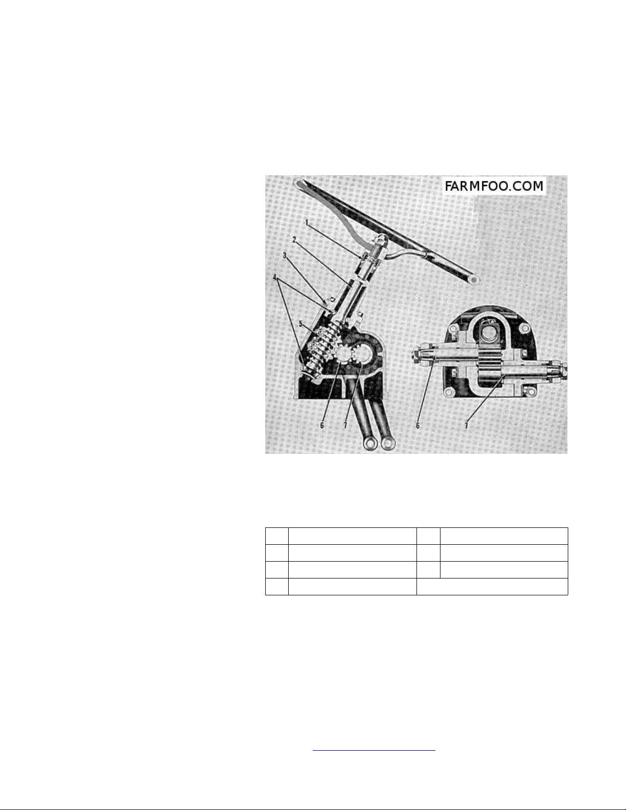
bearing adjustment is completed, hold ball nut and rotate worm shaft until nut
center tooth aligns with center of left sector shaft opening. See Fig. FO10.
Assemble left sector shaft (three large and four small teeth) and its housing to
gear housing, with center tooth of three large sector teeth meshed with center
space of teeth on ball nut as shown. The sector housing is installed with locating
notch at bottom. Adjust left sector backlash as described in paragraph 8.
Assemble right sector, meshing
center tooth of same with third
tooth space on left sector
gear, counting from solid
section of gear located on
bottom as shown in Fig. FO10.
Right sector center tooth is
marked on end of tooth and left
sector tooth space is similarly
marked. Adjust backlash as
described in paragraph 8. Fill
gear housing with SAE 90 oil
through filler hole in side of
housing and reinstall assembly.
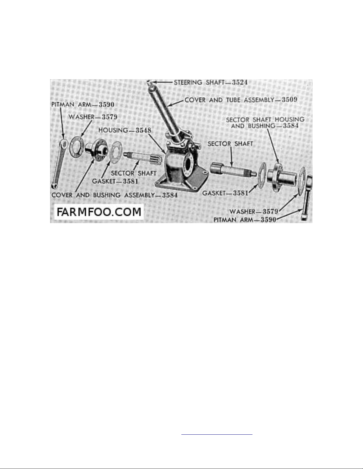
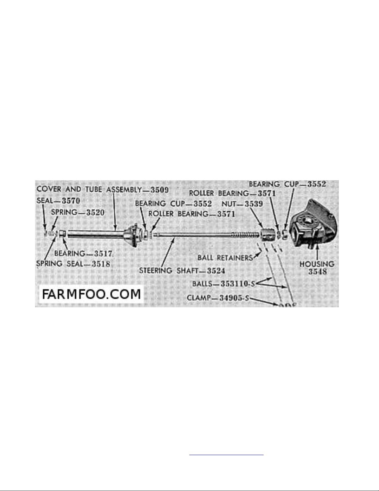
FIG. FO11 Disassembled worm–
shaft for steering gear used on
8N prior to tractor serial
216989. Nut (3539) and steering
shaft (3524) are not sold
separately.
FIG. FO10 Cross section side and top views of –
steering gear unit used on model 8N prior to
tractor serial 216989. Sectors (6&7) have
Model 8N After 216988
12. ADJUSTMENT. Before making
any adjustments, disconnect
both drag links at sector shaft
arms and back off right and
left side sector adjusting
straight teeth and left sector (6) is meshed with
ball nut.
1. Shaft upper bearing 5. Ball nut
2. Shaft and worm 6. Left sector
3. Shims 7. Right sector
4. Worm bearings
screws FIG. FO12A two full
turns after loosening the lock nuts. Check adjustment of wormshaft bearings by
pulling up and pushing down on steering wheel. If any up and down play is present,
adjust to zero end play by varying the shims located at bottom of steering tube and
cover. Adjustment is correct when the pull (measured at outer end of steering wheel
spoke) required to keep the steering wheel in motion after it has crossed the mid
or center point, is 1/2 to 1-1/2 pounds measured with a spring scale. Shims are
available in thicknesses of .002, .005, .010, and .030.
Connect/Report Errors – jcchapster@gmail.com
FO-4 I&T (Remastered Ver.1.2 ) 05-24-2015
13. SECTOR ARMS BACKLASH. Before adjusting sector mesh, make sure that wormshaft
bearings are correctly adjusted as outlined in paragraph 12. Make sure that drag
links are disconnected at sector shaft arms and back off right and left side sector
adjusting screws (Fig. FO12A) two full turns. Turn steering wheel to mid or wheelsstraight-ahead position. Now, using a screwdriver rotate the right hand sector
adjusting screw (viewed from rear of tractor) until all backlash is removed from
right sector arm. Correct adjustment is when 2 to 3 pounds of pull is required to
maintain the steering wheel in motion through the straight ahead or mid-position,
drag links disconnected and opposite sector adjustment backed off. After adjusting
the right hand sector as just mentioned, repeat the procedure on the left sector. A
pull of 2-1/2 to 6 pounds (measured at rim end of wheel spoke) should be required
to maintain the steering wheel in motion through the mid or straight-ahead position
after both of the sectors and the steering post bearings have been adjusted and
drag links disconnected.
Fig. FO11 - Disassembled worm shaft for steering gear used on 8N prior to tractor
serial 216989. Nut (3539) and steering shaft (3524) are not sold separately.
14. OVERHAUL. Major overhaul of gear unit necessitates the removal of the unit
from the tractor as per paragraph 11. Procedure for disassembly is self-evident.
Any derangement or wear in any of the components shaft and ball nut assembly (5 –
Fig. FO12) is corrected by renewal of the assembly as the individual parts are not
catalogued.
Connect/Report Errors – jcchapster@gmail.com

FO-4 I&T (Remastered Ver.1.2 ) 05-24-2015
Select and insert shims (9 Fig.–
FO12) between underside of inner head
of lash adjuster screws (2) and slot
in sectors to provide zero to .002
end play of adjuster screws in
sectors. Shims (9) are available in
thicknesses of .063, .065, .067 and
.069.
TOE-IN ADJUSTMENT
15. Toe-in is adjusted by varying
the length of the drag links. Models
2N 9N drag link is adjusted by–
disconnecting link front end,
loosening lock clamp and screwing
link end in or out as required. Model
8N drag links are provided with turnbuckle type adjustment and do not
require disconnection. The wheels may
be aligned approximately by adjusting
drag links until spindle arms are
centered over the radius rod to axle
member bolts or the reference marks.
Correct toe-in is 0 to 1/4 inch.
FIG. FO12A Cutaway of latest version of –
ball nut steering gear used on 8N tractors
after serial 216988. The filler plug may
be differently located on some 8N tractors
in this serial range.
Connect/Report Errors – jcchapster@gmail.com
FO-4 I&T (Remastered Ver.1.2 ) 05-24-2015
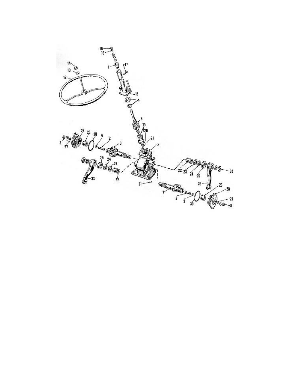
FIG. FO12 Exploded view of ball nut steering gear used on model 8N –
tractors after serial 216988. Sectors (7) have tapered teeth, and right
sector meshes with ball nut.
1. Shaft upper bearings 15. Seal 25. Seal
2. Sector adjusting screw 16. Spring 26. Steering gear arm (right)
3. Screw shaft adjusting
shims
4. Steering (screw) shaft
bearing
5. Screw shaft & nut assembly 20. Bearing retainer 29. Bushing
6. Left sector 21. Bearing retainer eyelet 30. “O” ring seal
7. Right sector 22. Bushing 33. Steering gear arm (left)
8. Lock nut 23. Packing
9. Shims 24. Retainer
18. Steering tube & cover 27. Lock washer
19. Steering shaft bearing 28. Sector cover
Connect/Report Errors – jcchapster@gmail.com

FO-4 I&T (Remastered Ver.1.2 ) 05-24-2015
Connect/Report Errors – jcchapster@gmail.com
FO-4 I&T (Remastered Ver.1.2 ) 05-24-2015
ENGINE AND COMPONENTS
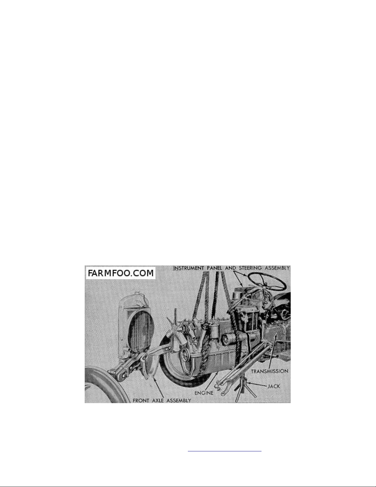
R & R ENGINE WITH CLUTCH
20. The engine and clutch assembly may be removed as a unit. Drain cooling system
and oil pan. Remove hood, disconnect battery ground strap and cable at starter.
Disconnect distributor and generator wires and cable at front end and swing wiring
out of way. Block up under transmission and support engine with a chain hoist.
Disconnect radiator hoses, clutch linkage and front axle support. Disconnect front
end of radius rod and mating drag link on either side, then swing axle and front
end assembly away from engine. Remove cap screws holding engine to transmission
housing and separate engine from housing. Reinstall engine in reverse order of
removal. See Fig. FO13.
CYLINDER HEAD R&R
21. Drain cooling system, remove hood and upper radiator hose. Remove ignition
cable harness and cylinder head stud nuts. Remove cylinder head and gasket. When
reinstalling head, tighten center stud nut first and progress alternately to ends
of head, using 50 55 foot pounds torque on nuts, 65 70 on cap screws.– –
FIG. FO13 Method of removing engine on models 2N-8N-9N.–
Connect/Report Errors – jcchapster@gmail.com
FO-4 I&T (Remastered Ver.1.2 ) 05-24-2015
VALVES
Inlet & Plain Exhaust
22. Inlet and exhaust valves are not
interchangeable. Valves removed for grinding or
refacing should be reinstalled in their
original location. Valves, guides and springs
are removed from the top after cylinder head
and valve chamber covers are off and valve
guide retainers are out.
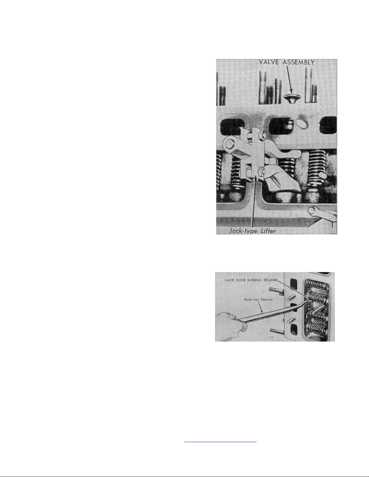
Use a hook type puller as shown in Fig. FO15 to
extract retainers from valve guides, then
remove each valve, guide and spring unit from
cylinder block with a jack type lifter as shown
in Fig. FO14. Renew valves having deeply pitted
or warped heads or stems that are bent or
scored or worn. Reface inlet and exhaust valves
to an angle of 45 degrees. Correct valve tappet
clearance cold is .010 to .013 for inlet and
from .014 to .016 for exhaust valves. On
engines with non-adjustable type tappets, grind
valve stem end to correct insufficient
clearance or grind valve head or seat faces to
correct excessive clearance. Use a lever type
tool to reinstall valve guide retainers as shown
in Fig. FO16.
Fig. FO14 Removing valve, valve–
spring and guide as an assembly.
Stem Diameter: Two-piece Guides .3105 - .3115
Stem Diameter: One-piece Guides .341 - .342
Clearance In Guide: Inlet .002 - .004
Clearance In Guide: Exhaust .0025 - .0045
Free Valve Type Exhaust
Fig. FO15 Removing valve guide –
22A. Follow procedure for removing and refacing
valves as outline in paragraph 22. On engines
with free type exhaust valve rotators, a gap or
end clearance of .0002 - .004 must exist between
cap and end of valve stem. Refer to paragraph 31 for checking procedure and method
of correcting the clearance. Correct valve tappet clearance is .010 - .012 cold for
inlet and .014 - .016 cold for exhaust valves.
Connect/Report Errors – jcchapster@gmail.com
retainer preparatory to removal of
valve, spring and guide as an
assembly.

FO-4 I&T (Remastered Ver.1.2 ) 05-24-2015
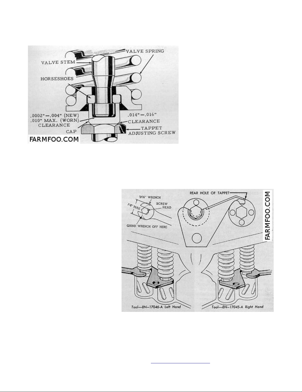
EXHAUST ROTORS
23. Some 8N engines are equipped with free valve type exhaust valve rotators which
are also available as a kit for engines not so equipped. Kit contains among other
items, 8 adjustable type tappets (pushrods), 4 exhaust valves equipped with special
caps and horseshoe type spring retainers as shown in Fig. FO17. Tappet clearances
of .010 - .012 cold for for inlet and .014 - .016 cold for exhaust valves are same
as on non-adjustable tappets, but rotator caps must be adjusted as outlined in
paragraph 27.
VALVE SEATS
24. All tractors except
model 2N tractors within the
serial range of 86271 to
168259 are equipped with
inlet and exhaust valves
seats of the hardened insert
type. Model 2N tractors
within the preceding serial
range are equipped only with
exhaust valve seat inserts.
If seat renewal is necessary
and special equipment for
that purpose is not
available; inserts may be removed as follows: Drill two holes partly through insert
on opposite sites using a drill smaller than insert width, then crack insert at
holes and remove the two halves. Counterbore in block must be .0015 to .003,
smaller than measured diameter of new seat insert. Pack new insert in dry ice for
at least 15 minutes and then drive or press it in place, making certain that it is
bottomed and not cocked. After insert is installed, grind the seat to 45 degrees
angle using a seating stone. If a seat cutter is used, each valve should be lapped
in its seat. Seat width should not exceed .125. If seat requires narrowing, use a
30 degree stone for top of seat and a 60 degree stone for the bottom.
Fig. FO16 Special tool for installing valve –
guide retainers.
VALVE GUIDES AND SPRINGS
25. Early production guides used in models 2N 9N and 8N tractors prior tractor –
serial 42162 are made in halves, and should be kept together with the mating valve,
to maintain stem to guide clearance. Later production guides used in model 8N
tractors after serial 42161 are one-piece type. Valves used with two-piece guides
have a stem diameter of .311; stem diameter of valves used with one-piece guides is
.341. Stem to guide clearance wear limit is .005 for inlet and .006 for exhaust
valves. New guides or guides with least wear should be used with inlet valves.
Connect/Report Errors – jcchapster@gmail.com
FO-4 I&T (Remastered Ver.1.2 ) 05-24-2015
Fig. FO17 - Free valve type exhaust valve rotators
used on later engines and available in kit form
for early engines.
The one-piece valve guides
can be installed in engines
originally equipped with the
two-piece type. If valve
rotators are not included in
the change-over, it will be
necessary to use the same
valve springs as used for the
two-piece type of guide.
Springs in tractors with twopiece valve guides should
test 37-40 pounds @ 2 1/8
inches; for one-piece guides
41-44 pounds @ 1.80 inches.
Renew valve springs if
protective pain coating is
lost or if tension is less
than specified.
VALVE PUSH RODS (TAPPETS)
26. Valve pushrods (tappets)
are of the barrel type. On
tractors built prior to 1951,
the tappets are of the nonadjustable type, later
tractors are equipped with
adjustable tappets.
Adjustable type tappets can
be installed in engines
originally equipped with the
non-adjustable type, and this
change-over is recommended.
Adjustable tappets are also
included in Ford Special
Equipment Kit 8N6546B which
provides special exhaust
valve rotators. This kit can
be installed in 2N, 9N and
early 8N tractors. Tappet
clearances (gaps) of .010 - .
012 inlet, .014 - .016
exhaust, cold, are used on
both types of tappets.
Fig. FO18 Showing special tappet holding wrenches–
needed for adjustment of Ford engines with
adjustable type tappets. A regular tappet end
wrench should be ground off as shown in upper left.
Method of adjusting the adjustable type tappets is shown in Fig. FO18. Required are
Connect/Report Errors – jcchapster@gmail.com
 Loading...