

Ford 6.4L Power Stroke User Manual
6.4L Power Stroke® Diesel Engine
2008 “F” SERIES SUPER DUTY
• Engine Description • Systems Overview • Component Location • Technician Tips •

FORWARD
This publication is intended to provide technicians and service personnel with an overview of
technical advancements in the 6.4L POWER STROKE® DIESEL Engine. The information contained in
this publication will supplement information contained in available service literature.
IMPORTANT SAFETY NOTICE
Appropriate service methods and proper repair procedures are essential for the
safe, reliable operation of all motor vehicles, as well as, the personal safety of
the individual performing the work. This manual provides general directions for
accomplishing service repair work with tested, effective techniques. Following the
directions will assure reliability. There are numerous variations in the procedures;
techniques, tools, parts for servicing vehicles and the skill of the individual doing
the work. This manual cannot possibly anticipate all such variations and provide
advice or cautions as to each. Accordingly, anyone who departs from the instructions
provided in this manual must first establish that they do not compromise their
personal safety or the vehicle integrity by their choice of methods, tools or parts.
The following list contains some general WARNINGS that you should follow when you
work on a vehicle.
Always wear safety glasses for eye protection.
Always perform work in a well ventilated area.
Use safety stands whenever a procedure requires you to be under the vehicle.
Be sure that the ignition switch is always in the OFF position, unless otherwise
required by the procedure.
Never perform any service to the engine with the air cleaner removed and the engine
running unless a turbocharger compressor inlet shield is installed.
Set the parking brake when working on the vehicle. If you have an automatic
transmission, set it in PARK unless instructed otherwise for a specific service
operation. If you have a manual transmission, it should be in REVERSE (engine OFF) or
NEUTRAL (engine ON) unless instructed otherwise for a specific service operation.
Operate the engine only in a well-ventilated area to avoid the danger of
carbon monoxide.
Keep yourself and your clothing away from moving parts when the engine is running,
especially the fan, belts, and the turbocharger compressor.
To prevent serious burns, avoid contact with hot metal parts such as the radiator,
turbocharger pipes, exhaust manifold, tail pipe, catalytic converter and muffler.
Do not smoke while working on the vehicle.
To avoid injury, always remove rings, watches, loose hanging jewelry, and loose
clothing before beginning to work on a vehicle. Tie long hair securely behind the head.
Keep hands and other objects clear of the radiator fan blades.
1

This page intentionally
left blank
2

6.4L POWER STROKE® DIESEL
TABLE OF CONTENTS
OVERVIEW . . . . . . . . . . . . . . . . . . . . . . . . . . . . . . . . . . . . . . . . . . . . . . . . . . . . . . . . . . . . . . . . . . 6
Features . . . . . . . . . . . . . . . . . . . . . . . . . . . . . . . . . . . . . . . . . . . . . . . . . . . . . . . . . . . . . . . . . . . . . . . . . . . . . . . . . .6
Horsepower & Torque. . . . . . . . . . . . . . . . . . . . . . . . . . . . . . . . . . . . . . . . . . . . . . . . . . . . . . . . . . . . . . . . . . .6
Specifications . . . . . . . . . . . . . . . . . . . . . . . . . . . . . . . . . . . . . . . . . . . . . . . . . . . . . . . . . . . . . . . . . . . . . . . . . . .7
Identification . . . . . . . . . . . . . . . . . . . . . . . . . . . . . . . . . . . . . . . . . . . . . . . . . . . . . . . . . . . . . . . . . . . . . . . . . . . .8
COMPONENT LOCATIONS. . . . . . . . . . . . . . . . . . . . . . . . . . . . . . . . . . . . . . . . . . . 9
Features . . . . . . . . . . . . . . . . . . . . . . . . . . . . . . . . . . . . . . . . . . . . . . . . . . . . . . . . . . . . . . . . . . . . . . . . . . . . . . . . 14
COOLING SYSTEM . . . . . . . . . . . . . . . . . . . . . . . . . . . . . . . . . . . . . . . . . . . . . . . . . . . . 16
Internal Coolant Flow. . . . . . . . . . . . . . . . . . . . . . . . . . . . . . . . . . . . . . . . . . . . . . . . . . . . . . . . . . . . . . . . . 16
External Coolant Flow . . . . . . . . . . . . . . . . . . . . . . . . . . . . . . . . . . . . . . . . . . . . . . . . . . . . . . . . . . . . . . . . 17
Coolant Pump. . . . . . . . . . . . . . . . . . . . . . . . . . . . . . . . . . . . . . . . . . . . . . . . . . . . . . . . . . . . . . . . . . . . . . . . . . 19
LUBRICATION SYSTEM. . . . . . . . . . . . . . . . . . . . . . . . . . . . . . . . . . . . . . . . . . . . . 21
Base Engine Flow . . . . . . . . . . . . . . . . . . . . . . . . . . . . . . . . . . . . . . . . . . . . . . . . . . . . . . . . . . . . . . . . . . . . . 21
System Flow . . . . . . . . . . . . . . . . . . . . . . . . . . . . . . . . . . . . . . . . . . . . . . . . . . . . . . . . . . . . . . . . . . . . . . . . . . . 22
FUEL SUPPLY SYSTEM . . . . . . . . . . . . . . . . . . . . . . . . . . . . . . . . . . . . . . . . . . . . . 28
System Flow . . . . . . . . . . . . . . . . . . . . . . . . . . . . . . . . . . . . . . . . . . . . . . . . . . . . . . . . . . . . . . . . . . . . . . . . . . . 29
AIR MANAGEMENT SYSTEM. . . . . . . . . . . . . . . . . . . . . . . . . . . . . . . . . . . . 33
System Flow . . . . . . . . . . . . . . . . . . . . . . . . . . . . . . . . . . . . . . . . . . . . . . . . . . . . . . . . . . . . . . . . . . . . . . . . . . . 34
Series Sequential Turbocharger . . . . . . . . . . . . . . . . . . . . . . . . . . . . . . . . . . . . . . . . . . . . . . . . . . . . . 36
EGR . . . . . . . . . . . . . . . . . . . . . . . . . . . . . . . . . . . . . . . . . . . . . . . . . . . . . . . . . . . . . . . . . . . . . . . . . . . . . . . . . . . . . 39
FUEL MANAGEMENT SYSTEM . . . . . . . . . . . . . . . . . . . . . . . . . . . . . . . . . 41
System Flow . . . . . . . . . . . . . . . . . . . . . . . . . . . . . . . . . . . . . . . . . . . . . . . . . . . . . . . . . . . . . . . . . . . . . . . . . . . 42
High Pressure Fuel Injection Pump Flow . . . . . . . . . . . . . . . . . . . . . . . . . . . . . . . . . . . . . . . . . . . 43
Piezo Fuel Injectors. . . . . . . . . . . . . . . . . . . . . . . . . . . . . . . . . . . . . . . . . . . . . . . . . . . . . . . . . . . . . . . . . . . 45
Stages of Injection . . . . . . . . . . . . . . . . . . . . . . . . . . . . . . . . . . . . . . . . . . . . . . . . . . . . . . . . . . . . . . . . . . . . 47
ELECTRICAL COMPONENTS . . . . . . . . . . . . . . . . . . . . . . . . . . . . . . . . . . . . . 51
Sensors. . . . . . . . . . . . . . . . . . . . . . . . . . . . . . . . . . . . . . . . . . . . . . . . . . . . . . . . . . . . . . . . . . . . . . . . . . . . . . . . . 52
Control Devices . . . . . . . . . . . . . . . . . . . . . . . . . . . . . . . . . . . . . . . . . . . . . . . . . . . . . . . . . . . . . . . . . . . . . . . 68
Glow Plug Control Module (GPCM) . . . . . . . . . . . . . . . . . . . . . . . . . . . . . . . . . . . . . . . . . . . . . . . . . . 70
UNIQUE SERVICE PROCEDURES . . . . . . . . . . . . . . . . . . . . . . . . . . . . . . 73
APPENDIX. . . . . . . . . . . . . . . . . . . . . . . . . . . . . . . . . . . . . . . . . . . . . . . . . . . . . . . . . . . . . . . . . 81
Torque Charts. . . . . . . . . . . . . . . . . . . . . . . . . . . . . . . . . . . . . . . . . . . . . . . . . . . . . . . . . . . . . . . . . . . . . . . . . . 82
Wiring Diagram. . . . . . . . . . . . . . . . . . . . . . . . . . . . . . . . . . . . . . . . . . . . . . . . . . . . . . . . . . . . . . . . . . . . . . . . 88
Diagnostic Trouble Codes (DTC’s). . . . . . . . . . . . . . . . . . . . . . . . . . . . . . . . . . . . . . . . . . . . . . . . . . . 90
3

This page intentionally
left blank
4
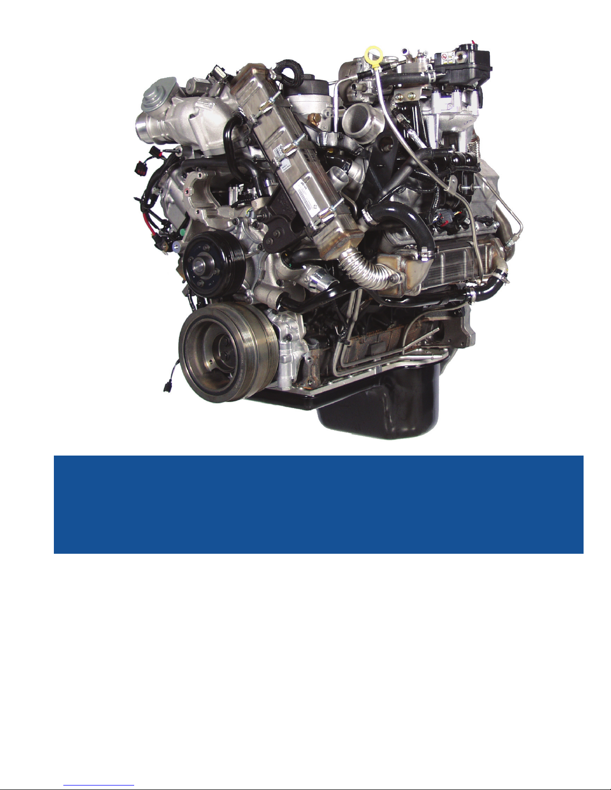
6.4L
Power Stroke® Diesel
Direct Injection
Turbocharged
Diesel Engine
5
6.4L POWER STROKE® DIESEL OvERvIEW
6.4L Power Stroke Diesel Overview
• This publication is not intended to replace the Service Manual
but to introduce the 6.4L Power Stroke® Diesel Engine.
1
Engine Features
• The 6.4L Power Stroke Diesel has been designed to meet
the tougher emissions standards set by the government.
• The 6.4L Power Stroke Diesel has been designed
to meet the customers’ expectations of high
horsepower and torque over a wide RPM range.
• Meeting the more stringent customer and regulated
demands are accomplished in part by: High Pressure
Common Rail Fuel System, Series Sequential Turbocharger
System, 4 valves per cylinder, and a dual timing system.
6.4L Power Stroke Diesel
Direct Injected Turbocharged
Diesel Engine Overview
• Engine Features
• Horsepower & Torque
• Engine Specifications
• Physical ID
• Labeling
Engine Features
• High Pressure Common Rail Fuel System
• Series Sequential Turbocharger
• 4 Valves per Cylinder
• Rear Gear Train
• Dual Timing System
2
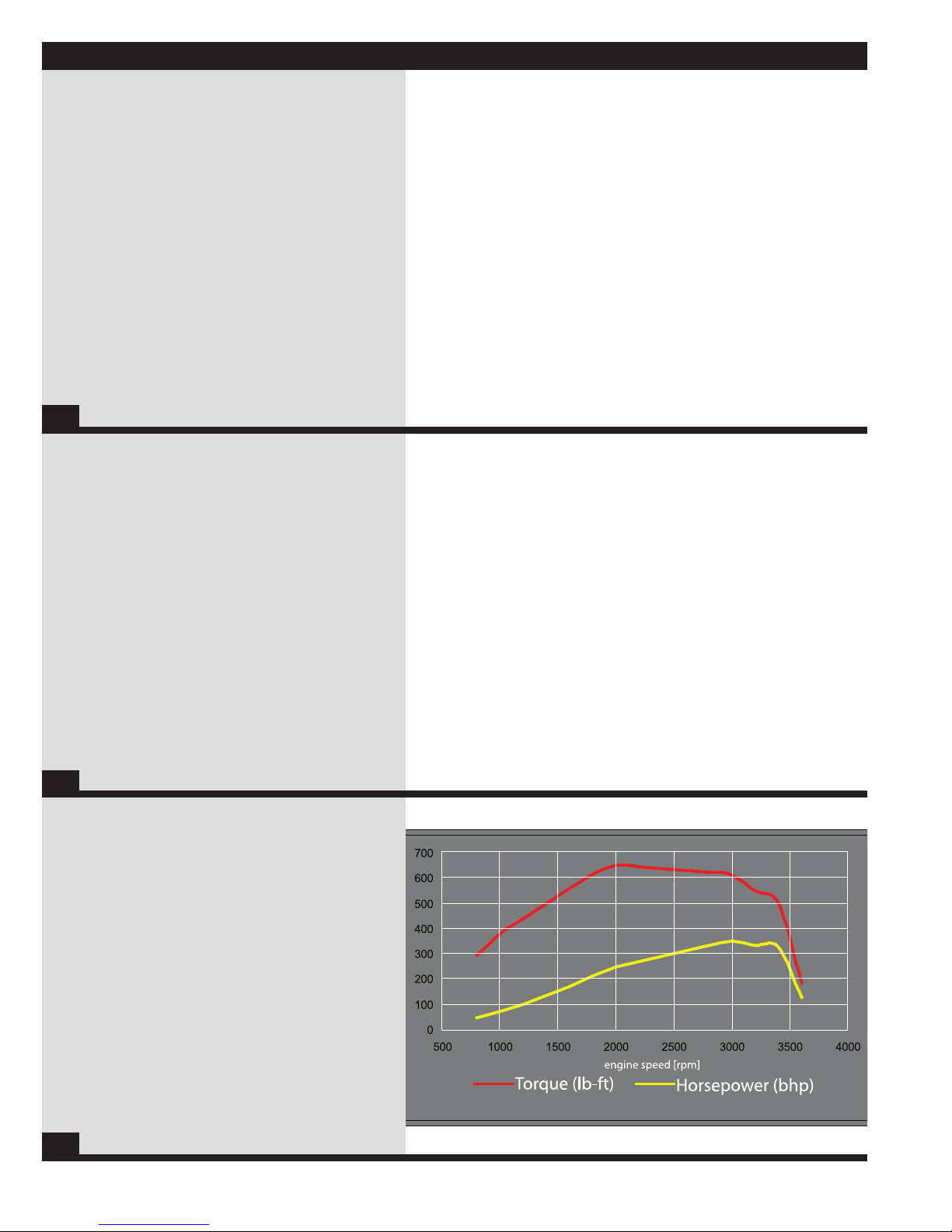
Horsepower & Torque
• The 6.4L Power Stroke Diesel creates 350 horsepower
at 3000rpm and 650 lb/ft of torque at 2000rpm.
3
6
6.4L POWER STROKE® DIESEL OvERvIEW
6.4L Power Stroke Diesel Specifications
Engine Type ...........................................................................................Diesel, 4 Cycle
Configuration ................................................................4 OHV/1 Cam-in-Crankcase-V8
Displacement .....................................................................................390 cu. in. (6.4L)
Bore & Stroke ................................................................3.87 X 4.134 (98.2 X 105 mm)
Compression Ratio .............................................................................................17.5:1
Aspiration .................................................................Series Sequential Turbo with CAC
Rated Power @ RPM ..........................................................................350 @ 3000 RPM
Peak Torque @ RPM ...........................................................................650 @ 2000 RPM
Engine Rotation, Facing Flywheel ....................................................Counter Clockwise
Combustion System ...................................High Pressure Common Rail Direct Injection
Total Engine Weight (auto with oil) ................................................1130 lb. (498.95 kg)
Coolant Flow (to radiator)....................................125 gal/min (473 L/min) @ 3000 RPM
Air Flow @ RPM (compressor inlet).......................744 CFM (21.1 m3/min) @ 3000 RPM
Exhaust Flow @ RPM (engine outlet)..................1962 CFM (55.6 m3/min) @ 3000 RPM
Oil Flow @ RPM .....................................................13 gal/min (59 L/min) @ 3000 RPM
Cooling System Capacity (engine only) ..................................................25.3 qts (24 L)
Lube System Capacity (including filter) ................................................15 qts. (14.2 L)
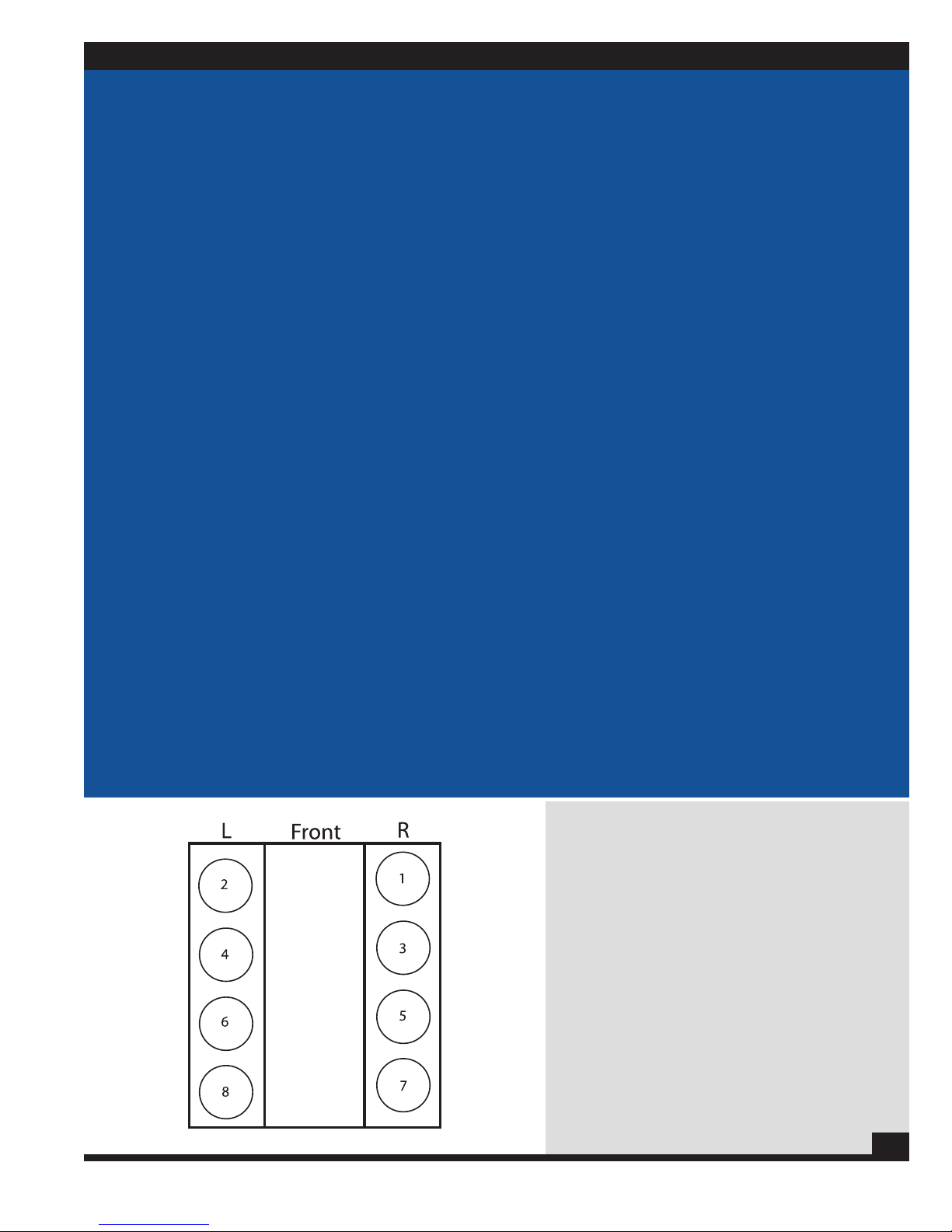
Firing Order ........................................................................................1-2-7-3-4-5-6-8
Specifications
• The cylinders of the 6.4L Power Stroke Diesel are
numbered from the front on the right side 1,3,5,7
and from the front on the left side 2,4,6,8.
4
7
6.4L POWER STROKE® DIESEL OvERvIEW
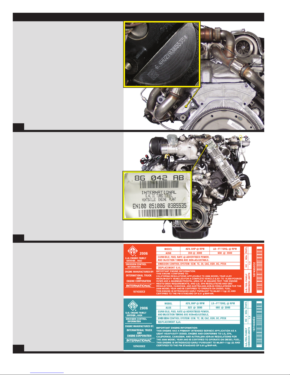
Engine Serial Number
• The engine serial number is located on the left rear corner
of the crank case on a half moon machined surface.
• A white sticker is placed over this number during production,
this sticker was removed for illustration purposes.
• 6.4 - is the engine family identifier.
• HU2Y - is a manufacturing designator
Ex: HU2Y or HU2U “Y designates Huntsville, AL
and U designates Indianapolis, IN”
• 0385535 - is a sequential build number
5
Serial Number Label
• Located on the top of the vertical EGR cooler.
• States the engine serial number.
- example at right, “0385535”
• States the engine family.
- example at right, “6.4L DI turbo diesel”
6
Emissions Label
• States the horsepower rating for the engine,
programmed in the Engine Control Module (ECM).
• Depicts where the engine meets or
exceeds emission standards.
• Shows the engine displacement.
• Is affixed to the right hand valve cover.
• F250/350 labels are red.
• F450/550 labels are blue.
7
8
COmPOnEnT LOCAT I O n S
3
4
2
1
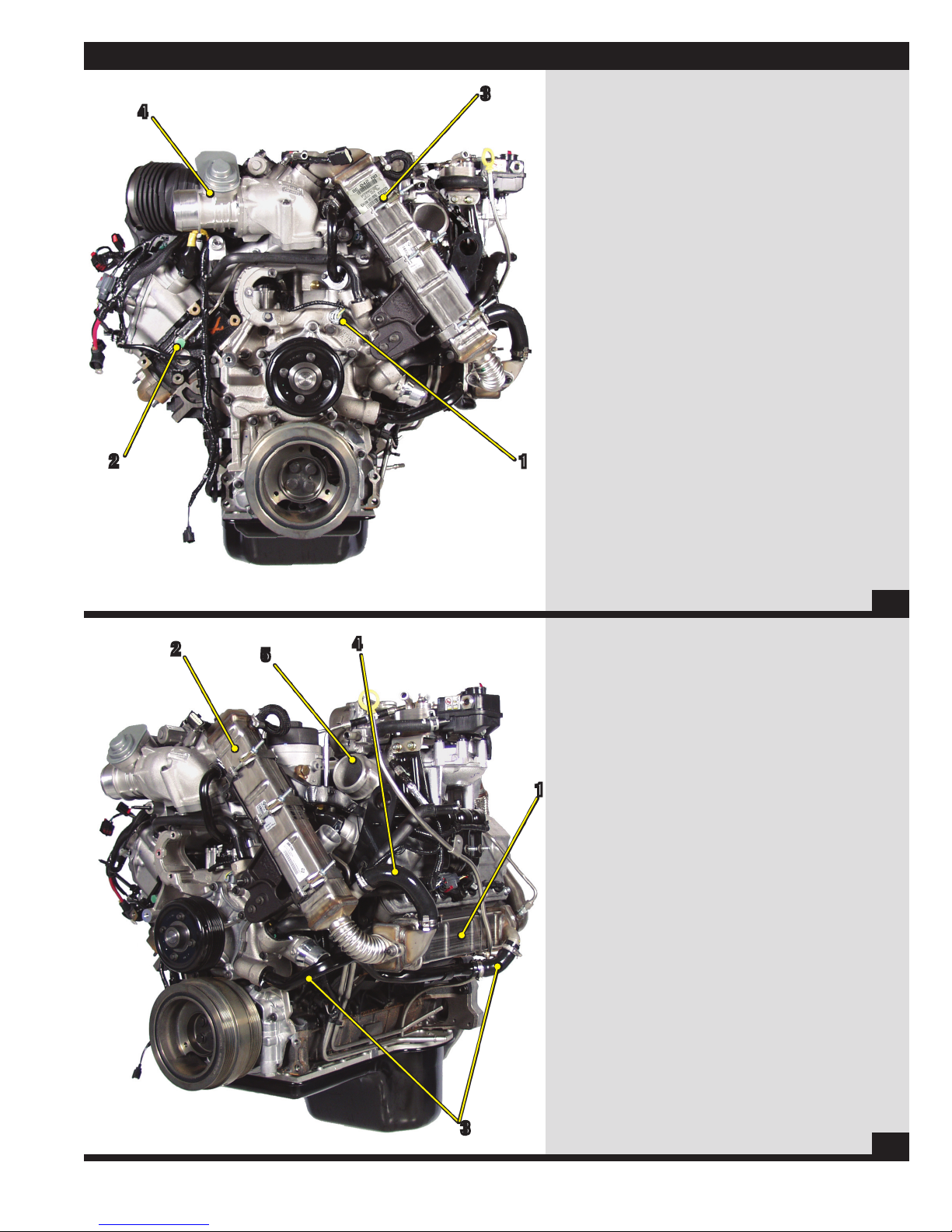
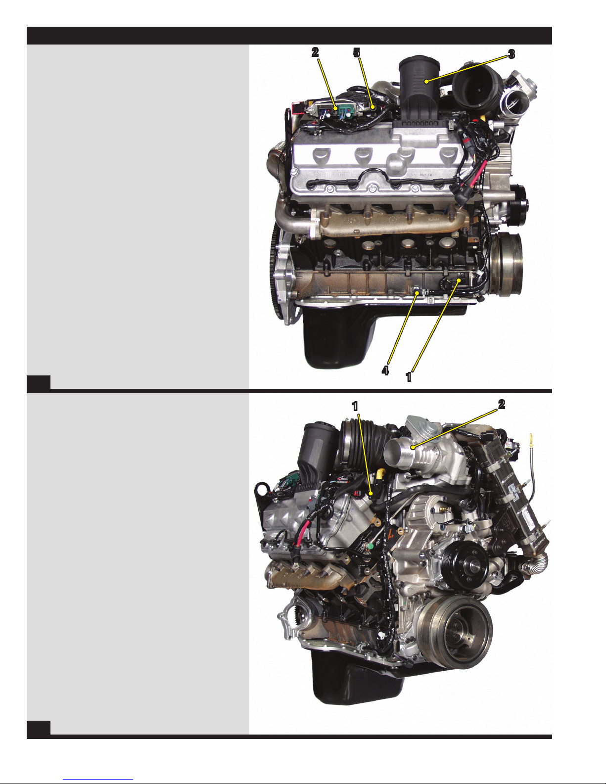
Front of Engine
1) ECT Sensor
2) Fuel Return Line
3) EGR Cooler Vertical
4) EGR Throttle
8
2
5
4
1
Left Front of Engine
1) EGR Cooler Horizontal
2) EGR Cooler Vertical
3) Coolant Supply for Horizontal Cooler
4) Coolant Supply for Vertical Cooler
5) Turbocharger Outlet
3
9
9
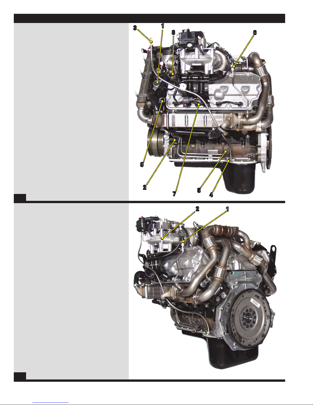
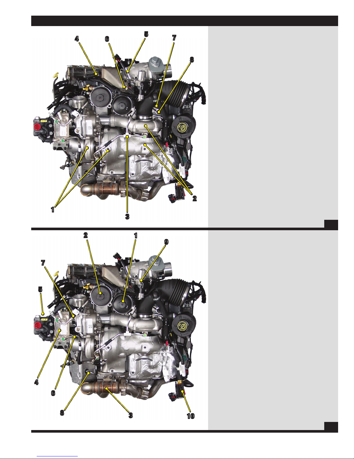
Left of Engine
1) Thermostat Housing Outlet
2) CMP Sensor
3) Oil Level Gauge
4) Fuel Supply Line
5) Fuel Return Line
6) EP Sensor
7) Glow Plug Harness
8) Heater Return Line
9) Degas Bottle Return Line
COmPOnEnT LOCAT I O n S
3
1
8
9
6
10
Left Rear of Engine
1) EP Sensor
2) Turbocharger Crossover Tube
2
7
5
4
2
1
11
10
COmPOnEnT LOCAT I O n S
2
1
5
3
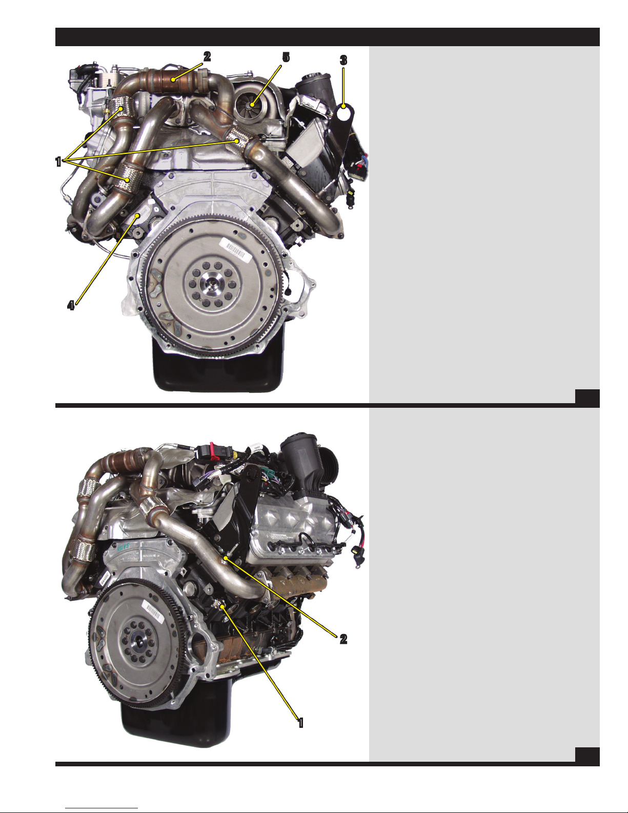
Rear of Engine
1) Exhaust Expansion Joints
2) Catalyst
3) Lifting Eye
4) Serial Number
5) Turbocharger Outlet to Exhaust System
4
12
Right Rear of Engine
1) Block Heater
2) EGRT Inlet Sensor
2
1
13
11
Right Side of Engine
1) CKP Sensor
2) Glow Plug Control Module
3) Crankcase Ventilation/Oil Separator
4) Oil Seperator Drain Tube
5) Heater Supply
COmPOnEnT LOCAT I O n S
2
5
3
14
Right Front of Engine
1) Injector Electrical Connector
2) Throttle Body
4
1
1
2
15
12
COmPOnEnT LOCAT I O n S
4
6
5
7
8
Top of Engine
1) High Pressure Turbocharger
2) Low Pressure Turbocharger
3) Turbocharger Oil Supply Line
4) EGR Valve Coolant Supply Port
5) EGR Valve Coolant Return Port/Deaeration Port
6) EGRT Outlet Sensor
7) MAP Sensor
8) IAT 2 Sensor
2
1
3
16
2
7
5
1
9
Top of Engine
1) Oil Filter
2) Engine Mounted Fuel Filter
3) Catalyst
4) Fuel Cooler
5) Fuel Cooler Coolant Tank
6) Fuel Return Hot (inlet to cooler)
7) Fuel Return Cold (outlet from cooler)
8) LH High Pressure Fuel Line
9) EGR Valve
10) ECM Connection
4
6
8
3
10
17
13
6.4L POWER STROKE® DIESEL OvERvIEW
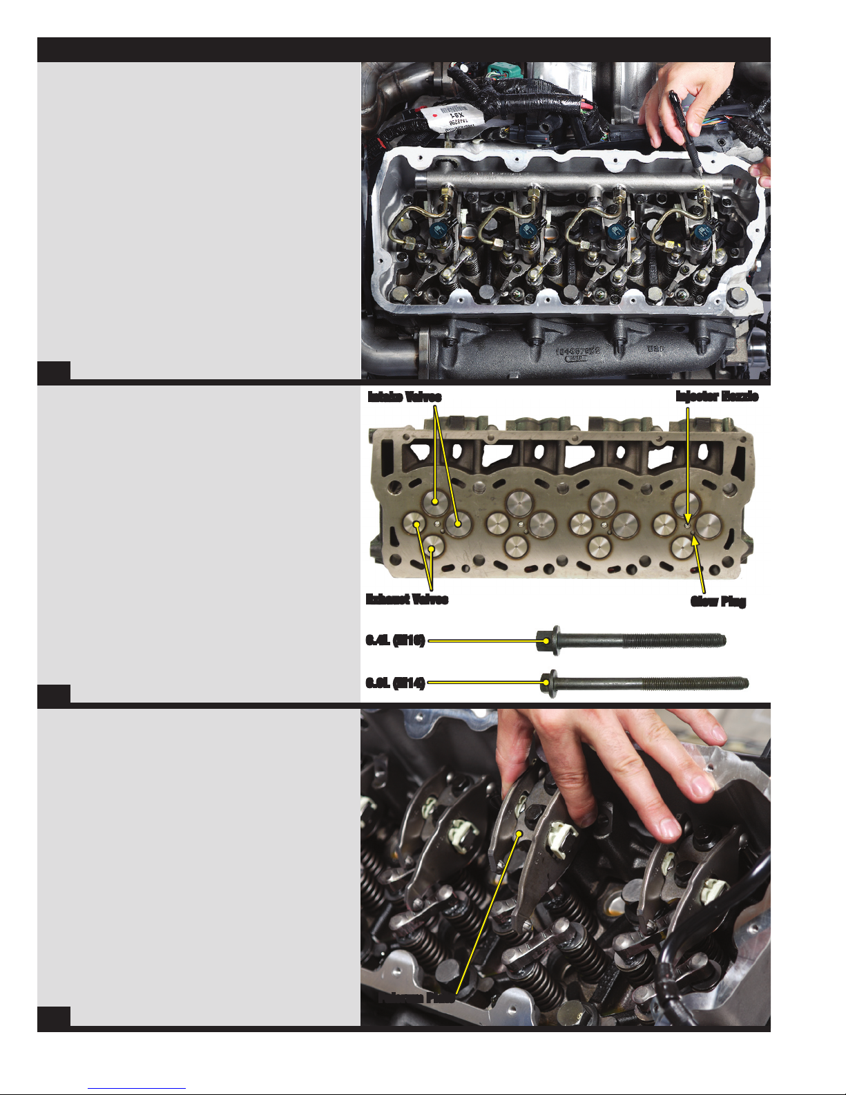
High Pressure Common Rail Fuel System
• The 6.4L Power Stroke Diesel engine uses a
high pressure fuel injection pump to deliver fuel
to each piezo electric fuel injector via a high
pressure common fuel rail, one rail per bank.
18
Cylinder Head & Head Bolts
• The 6.4L Power Stroke Diesel uses a four (4) valve per
cylinder head design to optimize airflow and efficiency.
Intake Valves
Injector Nozzle
• The 6.4L Power Stroke Diesel engine uses larger head bolts
than the 6.0L Power Stroke Diesel engine (M16 vs M14).
• The 6.4L head bolts are also slightly shorter than the
6.0L head bolts. The 6.4L head bolts do not retain
the rocker carrier like the 6.0L head bolts do.
19
Fulcrum Plate & Rocker Arms
• The fulcrum plate, which holds the rocker
arms, is bolted to the rocker pedestal.
• The two (2) bolts that secure the fulcrum plate pass
through the fulcrum plate and the rocker pedestal
and are then secured into the cylinder head.
Exhaust Valves
6.4L (M16)
6.0L (M14)
Glow Plug
20
Fulcrum Plate
14
6.4L POWER STROKE® DIESEL OvERvIEW
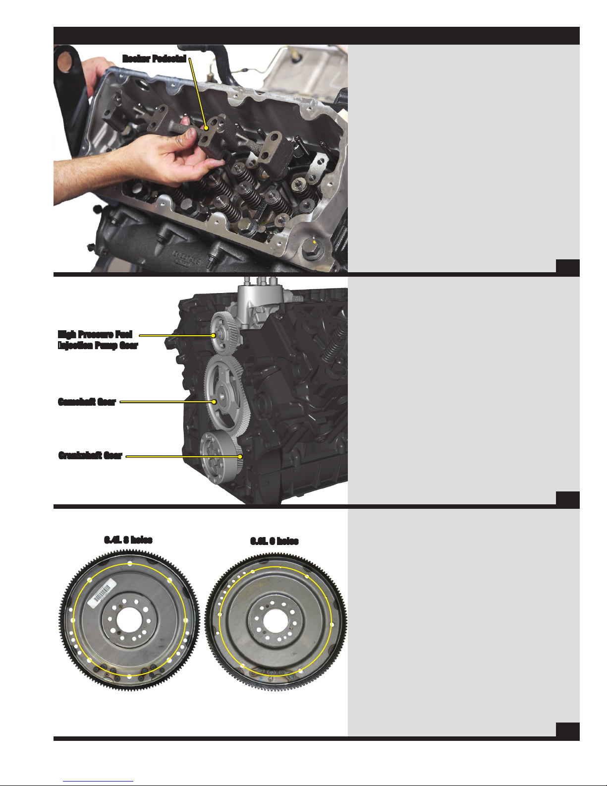
Rocker Pedestal
High Pressure Fuel
Injection Pump Gear
Rocker Pedestal
• The rocker pedestal is secured independent of
the cylinder head bolts, which no longer need to
be removed to service the rocker arms.
21
High Pressure Fuel Injection Pump &
Rear Geartrain
• The geartrain for the crankshaft, camshaft, and
the high pressure fuel injection pump are located
in the rear of the engine under the rear cover.
• This allows for the high pressure fuel pump to be
mounted inside the engine and also reduces noise.
Camshaft Gear
Crankshaft Gear
6.4L 8 holes
6.0L 6 holes
• The high pressure fuel injection pump turns
at a ratio of 1:1 with crankshaft speed.
NOTE: The helical cut gears used on the 6.4L
differ from those used on the 6.0L.
22
6.4L vs 6.0L Flexplate
• The flexplate for the 6.4L automatic equipped engine
uses an 8 bolt torque converter bolt pattern.
• The flexplate for the 6.0L automatic equipped engine
uses a 6 bolt torque converter bolt pattern.
NOTE: Yellow circle added for bolt circle reference.
23
15
Cooling system
Cooling System Features
• The coolant pump can be serviced without disconnecting
radiator hoses.
• Both the glow plug sleeves and the injector sleeves are
stainless steel.
24
Cooling System Features
• Coolant Pump
• Stainless Steel Injector Sleeves
• Stainless Steel Glow Plug Sleeves
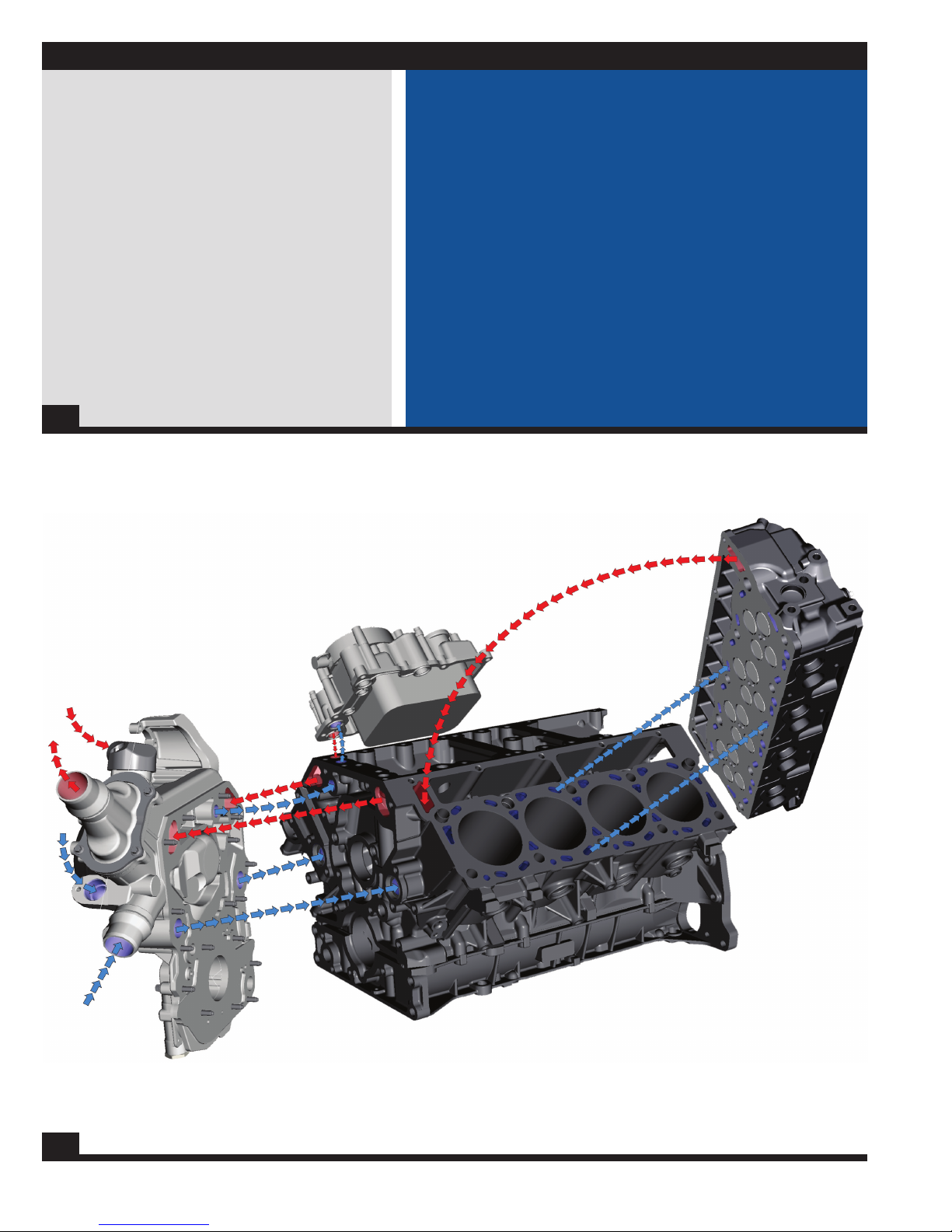
Internal Coolant Flow
25
16
Cooling system
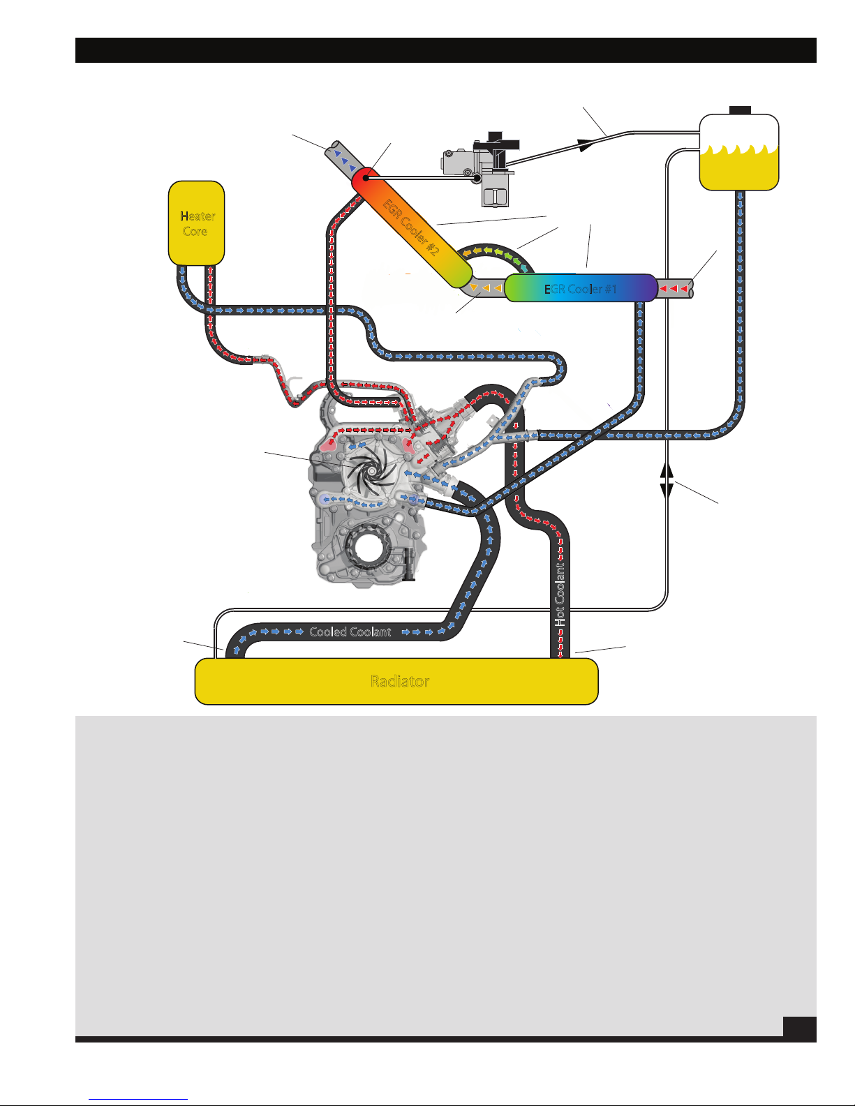
EGR Cooler #1
Radiator
Degas
Bottle
Heater
Core
EGR Cooler #2
Coolant feed
to EGR valve
Hot coolant
from pump to
top radiator port
Cooled coolant
to pump from
bottom radiator port
Radiator fill/
Overflow supply
to degas bottle
(flow in either direction)
Coolant Pump
Color change indicates
coolant temperature
as heat is transfered
from exhaust gases
to the coolant
Hot exhaust
in from right
up-pipe
Partially cooled
exhaust gases
Cooled exhaust
out to EGR valve
Hot Coolant
Cooled Coolant
Deaeration/coolant feed
to degas bottle
External Coolant Flow
Cooling System Flow: External Flow
• Coolant is drawn into the inlet of the front cover from the bottom
radiator port and then flows from the coolant pump through the front
cover to the crankcase.
• Coolant is also routed from the front cover into the crankcase to a
passage that feeds the oil cooler (shown on next page).
• Coolant is routed from the front cover to the EGR coolers, EGR valve,
degas bottle, and the vehicle heater core.
• The horizontal EGR cooler receives coolant first, then the coolant
travels to the vertical EGR cooler through a short connection hose.
Hot coolant exits the vertical EGR cooler at the top and enters into
the front cover.
• A port next to the hot EGR return port in the front cover routes hot
coolant to the heater core for vehicle heating. The coolant then
travels to a Y-pipe where it meets with degas return coolant before
being sent into the front cover, just above the main coolant inlet from
the radiotor.
• The EGR valve receives its coolant from a passage at the top of
the vertical EGR cooler. Once the coolant exits the EGR valve it
is sent to the degas bottle (this passage is the highest point in
the system and is also the deaeration port).
• The port directly below the EGR valve return/deaeration port
on the degas bottle is used as a radiator fill/overflow line
connecting with the top of the radiator.
• A dual thermostat sytem is used to control the flow of return
coolant to the radiator. If the thermostats are open, coolant
flows to the radiator to be cooled. The bottom thermostat has
a bypass circuit that will allow coolant to return to the pump
when the thermostats are closed (speeding engine warm up).
17
26
Cooling system
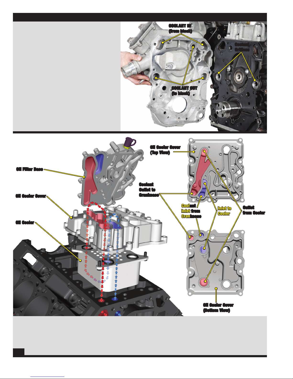
Cooling System Flow: Back of Front Cover
• Coolant is sealed via a metal one piece gasket and is
directed out of the front cover through three (3) passages.
• Two of the passages route coolant to the crankcase to cool
the cylinder walls and cylinder heads (there are different
sized orifices pressed into the crankcase in these two
passages).
• The third passage routes coolant to the oil cooler via a
passage in the crankcase.
• There are two passages for coolant to return from the
crankcase into the front cover.
Oil Cooler Coolant Flow
COOLANT IN
(from block)
Coolant
Orifices
COOLANT OUT
(to block)
Oil Cooler Cover
(Top View)
Oil Filter Base
Oil Cooler Cover
Oil Cooler
Coolant
Outlet to
Crankcase
Coolant
Inlet from
Crankcase
Inlet to
Cooler
Oil Cooler Cover
(Bottom View)
Outlet
from Cooler
Cooling System Flow: Oil Cooler
• Coolant is directed out of the crankcase and into the oil filter base at
the front of the engine.
• The oil filter base routes the coolant down into the front of the oil
cooler then toward the rear of the engine.
27
• Once the coolant has passed through the oil cooler it is routed
up to the top of the oil cooler then directed towards the front
through a port where it is then routed down, out of the cooler,
through a port in the block.
18
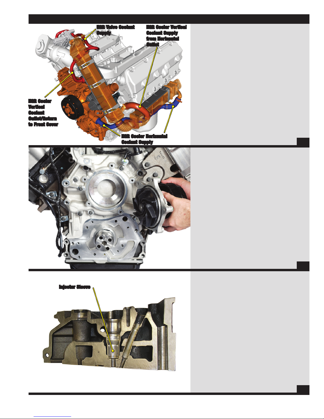
EGR Cooler
Vertical
Coolant
Outlet/Return
to Front Cover
EGR Valve Coolant
Supply
EGR Cooler Horizontal
Coolant Supply
Cooling system
EGR Cooler Vertical
Coolant Supply
from Horizontal
Outlet
Cooling System Flow: EGR Coolers
• Cooled coolant flows out of the supply port of the front
• The coolant then exits the horizontal cooler and is
• There is a small port at the top of the vertical cooler where
• Coolant flows through the EGR coolers and removes heat
Coolant Pump & Front Cover
• The coolant pump, (hub and impeller) is mounted into the
• The coolant pump impeller pulls coolant from the center of
• The coolant pump has a built in reservoir to catch small
Note: The coolant pump impeller may be
cover where it is routed to the horizontal cooler at the left
rear side of the engine.
immediately routed into the vertical cooler. The coolant
then exits the vertical cooler where it is routed to the return
port in the front cover.
coolant is allowed to flow to the EGR valve, cool the valve,
then the coolant is routed to the degas bottle. This port is
also used as the deaeration port.
from the exhaust before the exhaust arrives at the EGR
valve.
28
front cover which is the housing for the water pump.
the housing and pushes it outward.
amounts of coolant that during normal operation of the
engine may seep past the seal. This coolant will evaporate
over time.
damaged if dropped or hit by a hard object.
Injector Sleeve
29
Injector Sleeve
• The 6.4L Power Stroke uses stainless steel injector sleeves
to seal coolant from the injector and to transfer heat from
the injector to the coolant.
• The injector sleeve is replaceable.
30
19
Cooling system
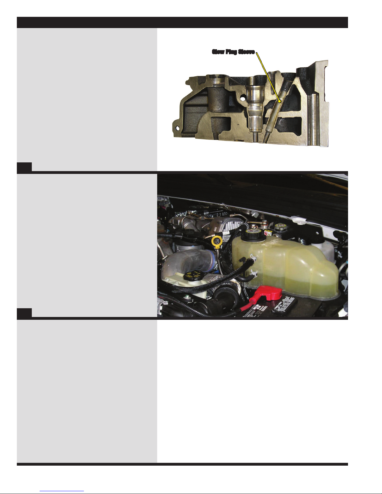
Glow Plug Sleeve
• Glow plug sleeves are used to keep coolant from coming in
direct contact with the glow plugs and to seal coolant from
the combustion chamber.
• The glow plug sleeve is replaceable. See unique service
procedures or the service manual for more details.
31
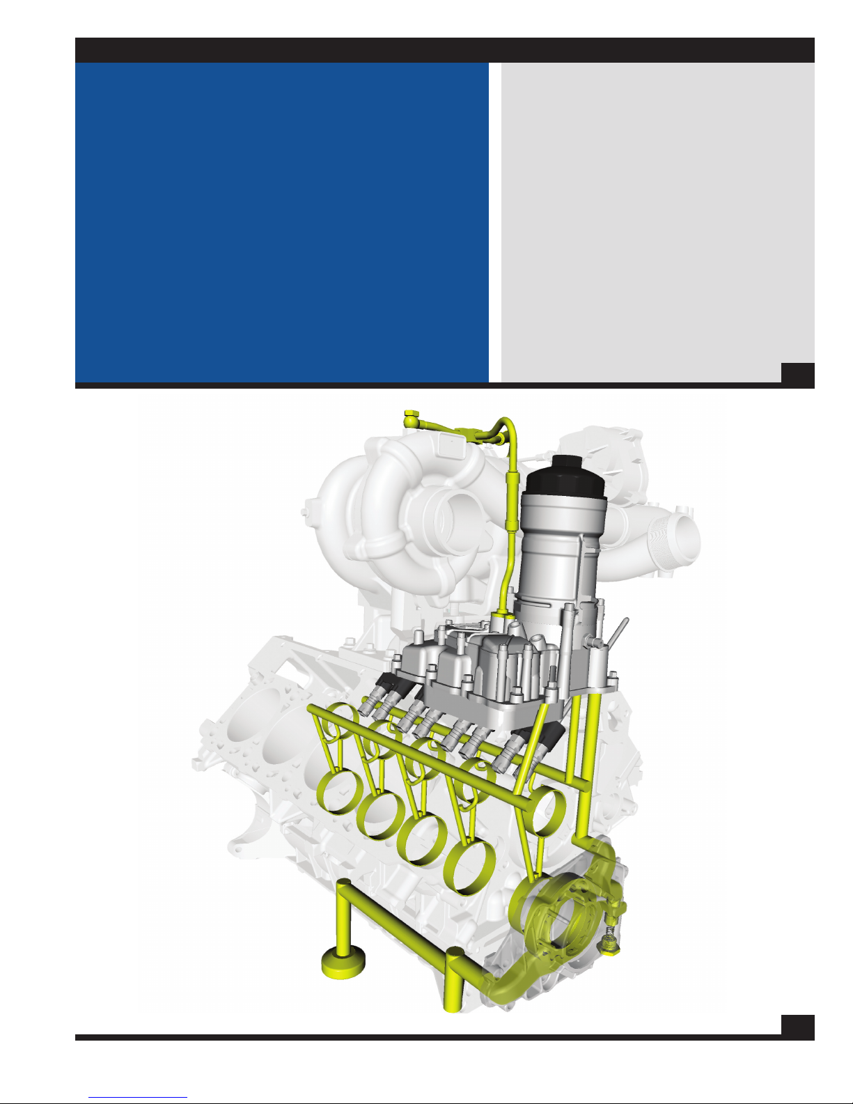
Degas Bottle
• The degas bottle is located on the left side of the engine
compartment and is part of the left side battery tray.
• One of the ports on the bottle is attached to the EGR valve
coolant line (which is supplied from the top of the vertical
EGR cooler). If this port or hose is blocked, damage could
occur to the EGR coolers and/or the EGR valve.
Glow Plug Sleeve
32
20
Lubricat i o n S y S t e m
Lubrication System Features
• Integrated Oil Cooler
• No External Oil Passages in Crankcase
• Easy Access Cartridge Style Oil Filter
• External Oil Pressure Regulator
Lubrication System Features
• The 6.4L Power Stroke® Diesel uses an oil cooler that is
mounted in the valley of the engine under the oil filter.
• The oil filter is a cartridge style filter mounted
on the top of the engine for ease of service. This
system also incorporates a valve that drains the
oil to the pan when the filter is removed.
• The gerotor oil pump and oil pressure regulator are both
located in the front of the engine behind the vibration
damper in their own removeable aluminum housing.
33
34
21
Lubricat i o n S y S t e m
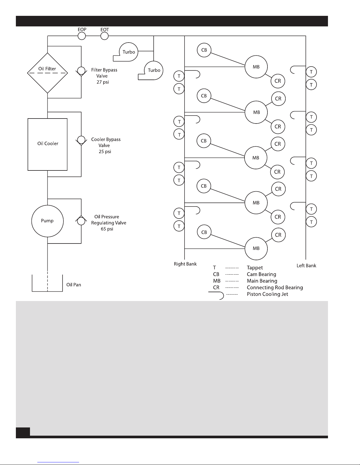
Lubrication System Oil Flow
• Oil is drawn from the oil pan through the pick-up tube. The
oil is then routed through a passage cast into the upper oil
pan before being routed through a passage in the block, a
passage in the front cover, and finally to the oil pump inlet.
• The regulator valve utilizes a force, provided via the regulator
spring, to apply a pressure equal to 65 psi. Whenever oil pressure
exceeds this force, the regulator valve will move downward
and allow the excess pressure to bleed off back through a
passage that routes the oil back to the inlet side of the pump.
• From the oil pump, oil is directed to the oil
cooler and then to the oil filter.
• From the oil filter the oil is supplied to a chamber incorporating
five (5) passages. One (1) is to the turbochargers for
lubrication. Two (2) are to the EOT and EOP sensors.
35
• The two (2) other passages are to the tappet oil
supply on the right and left banks. The tappet galleries
also provide oil to the piston cooling jets.
• Cross drillings off of the right bank tappet
gallery supply oil to the main bearings.
• Another cross drilling vertically up from each main
bearing supplies oil to the camshaft bearings.
Note: This oil supply routing is different than the 6.0L
and uses different bearings which are also placed
differently with respect to the oil holes.
22
Lubricat i o n S y S t e m
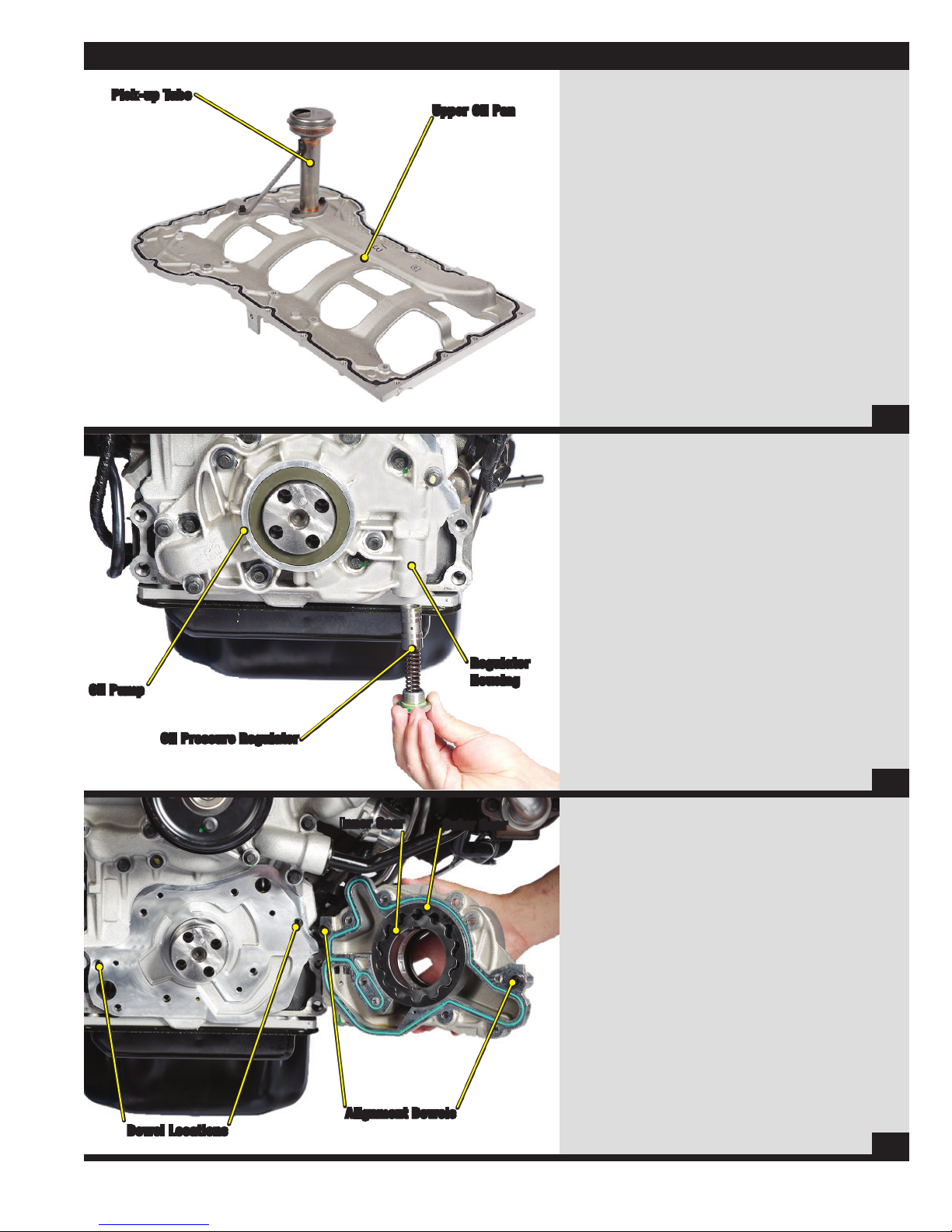
Pick-up Tube
Upper Oil Pan
Pick-up Tube / Oil Aeration
• The pick-up tube supplies oil from
the oil pan to the oil pump.
• The pick-up tube is sealed to the upper oil pan
utilizing an o-ring. If the o-ring is damaged
or missing, it could cause oil aeration.
36
Oil Pressure Regulator
• The oil pressure regulator is located in the gerotor
housing just to the right (when looking at the
engine from the front) of the gerotor oil pump.
• The oil pressure regulator is calibrated to
open at pressures above 65 psi. It should
be closed below that pressure.
Oil Pump
Oil Pressure Regulator
Inner Gear
Regulator
Housing
Outer Gear
• The regulator valve utilizes a force, provided via the
regulator spring, to apply a pressure equal to 65
psi. Whenever oil pressure exceeds this force, the
regulator valve will move downward and allow the
excess pressure to bleed off back through a passage
that routes the oil back to the inlet side of the pump.
37
Gerotor Oil Pump
• The gerotor oil pump is driven off of the
flats on the nose of the crankshaft.
• The gerotor oil pump and regulator valve are
held in their own removeable housing.
Dowel Locations
Alignment Dowels
38
23
Lubricat i o n S y S t e m
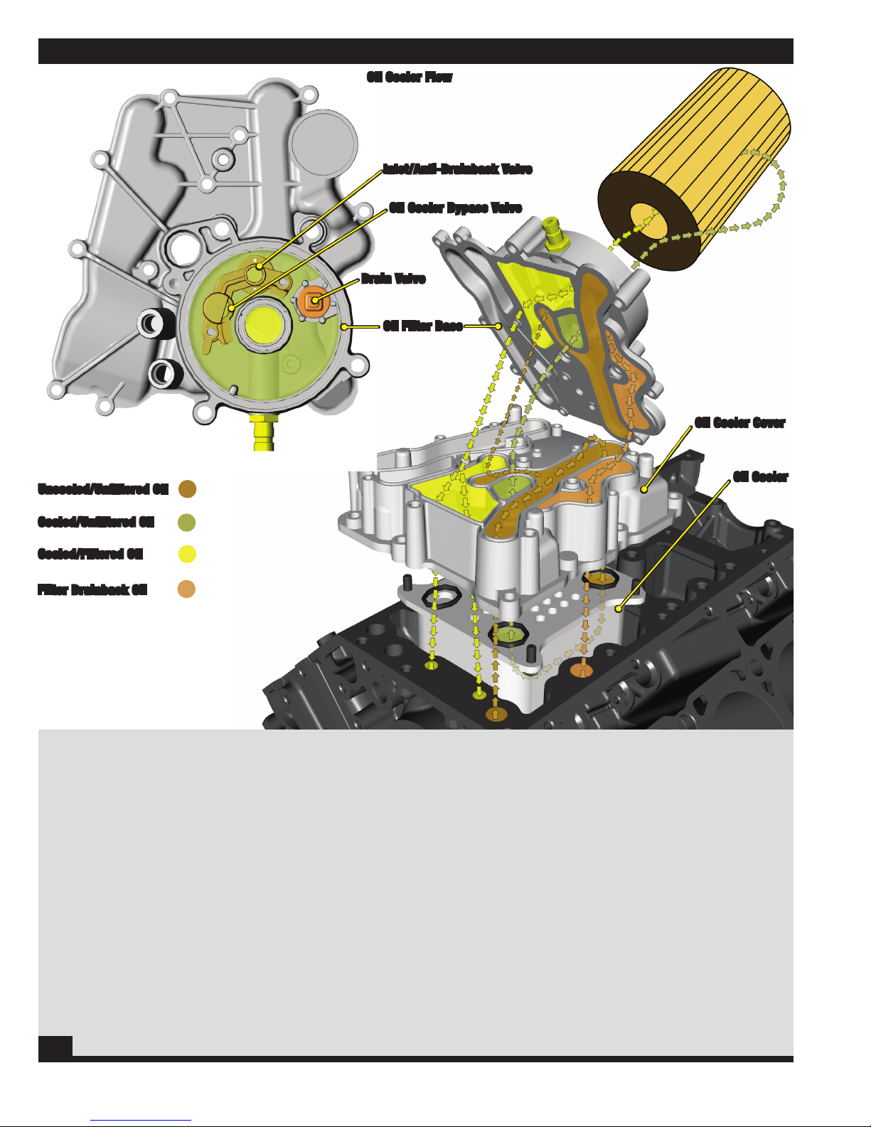
Oil Cooler Flow
Inlet/Anti-Drainback Valve
Oil Cooler Bypass Valve
Drain Valve
Oil Filter Base
Oil Cooler Cover
Uncooled/Unfiltered Oil
Cooled/Unfiltered Oil
Cooled/Filtered Oil
Filter Drainback Oil
Lube System Flow: Oil Cooler
• Uncooled/Unfiltered oil is directed out of the crankcase at the front
left corner of the engine via a drilled passage from the oil pump.
• Uncooled/Unfiltered oil is then directed across the
oil cooler cover then down into the oil cooler.
• The oil is then cooled via the oil cooler as it passes
through the cooler towards the front of the engine.
• The cooled/unfiltered oil is routed up through the oil cooler cover
then through the oil filter base where it enters the oil filter housing
(there is a small inlet valve in the oil filter base that the oil must
pass through to keep the oil from draining out of the filter housing
during non-operation). At this point the oil flows through the filter
(from the outside of the filter to the center) where it is cleaned.
Note: There is an oil filter bypass valve located at the top of
the oil filter stand pipe (plastic tube the oil filter slides over)
which will open and allow unfiltered oil to enter the system
whenever a pressure differential of 27 psi is reached.
39
Oil Cooler
• After being cleaned via the oil filter, the oil is routed through
the oil filter base and into a cavity that has ports to direct
the oil to the follwing areas: left and right oil galleries,
turbocharger oil supply, and the EOT & EOP sensors.
Note: There is a drain valve inside the oil filter base which is held
closed by the oil filter whenever the oil filter cap is tight. Whenever
this cap is loosened, the valve is allowed to open and oil will then
escape through this valve, through the oil cooler cover, and then
down through a drilled passage in the crankcase to the oil pan.
Note: There is an oil cooler bypass valve inside the oil
fllter base which will open and let uncooled oil bypass
the oil cooler and enter the oil filter housing whenever
a pressure differential of 25 psi is reached.
24
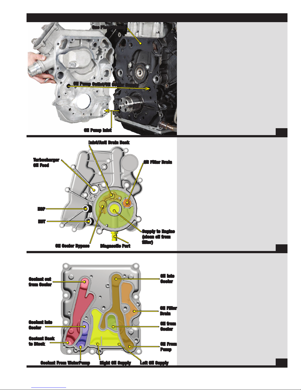
Lubricat i o n S y S t e m
Turbocharger
Oil Feed
One Piece Gasket
Oil Pump Outlet/Oil Cooler Supply
Oil Pump Inlet
Inlet/Anti Drain Back
Oil Filter Drain
Front Cover
• Oil flows from the crankcase to the oil pump
via a passage through the upper oil pan,
front cover, and oil pump housing.
• When the oil pump is turned by the crankshaft it creates oil
flow and pushes oil through two passages. One passage
is to the oil cooler and the other is through the oil pressure
regulator then to the oil pump inlet (this passage is only
used when pressure exceeds 65 psi). When the oil reaches
the numerous restrictions throughout the engine, pressure
is then created (pressure is the resistance to flow).
• All of the passages from the front cover to the crankcase
are sealed with a rubber coated metal, one piece gasket.
40
Oil Filter Base
• The oil filter base contains the mounting provisions
for the oil filter housing and the oil filter stand pipe
(which contains the oil filter bypass valve).
• Inside the oil filter housing, there are the following
valves: Inlet/Anti drainback valve, oil cooler
bypass valve, and the oil filter drain valve.
EOP
EOT
Coolant out
from Cooler
Coolant Into
Cooler
Coolant Back
to Block
Oil Cooler Bypass
Diagnostic Port
Supply to Engine
(clean oil from
filter)
Oil into
Cooler
Oil Filter
Drain
Oil from
Cooler
Oil From
Pump
• The oil filter base also contains the ports for the EOT, EOP,
and turbocharger oil supply. These ports are all connected
with the cooled/filtered oil passage directly beneath them.
41
Oil Cooler Cover
• The oil cooler cover has passages in it to
direct the flow of coolant and oil.
• Oil is routed from the front of the crankcase to the
rear of the housing where it enters the oil cooler. The
oil passes from the rear of the oil cooler to the front of
the cooler and is cooled in the process. The oil is then
sent to the oil filter through the oil filter base. Filtered
oil is sent to the oil passages in the crankcase, the
turbocharger supply line, and the EOT/EOP sensors.
• The coolant is directed from the front of the crankcase
to the front of the oil cooler. It then passes through the
oil cooler and cools the oil. As the coolant exits the front
of the cooler it is directed down into the coolant stream
where it re-enters the crankcase cooling system.
Note: If the oil cooler is damaged it could cause
contamination of the lubrication and cooling systems.
Coolant From WaterPump
Right Oil Supply Left Oil Supply
42
25
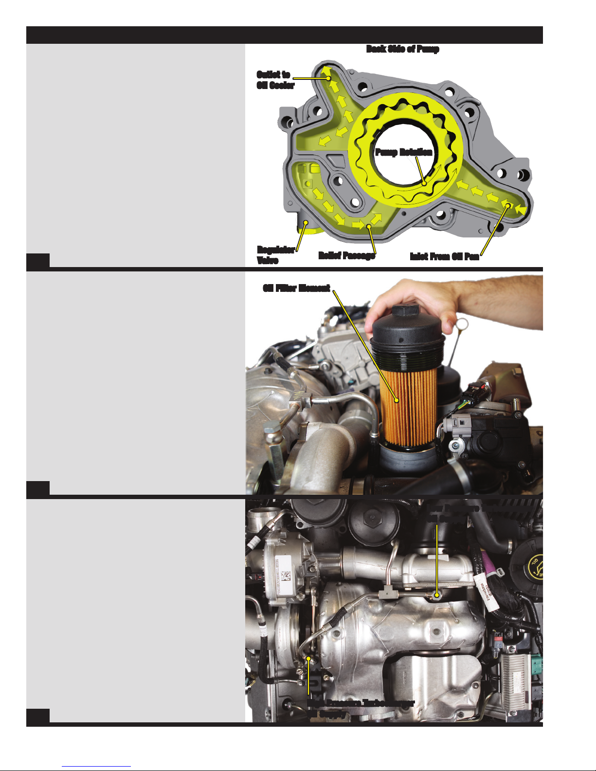
Lubricat i o n S y S t e m
Oil Pump Flow (back side)
• The oil pump is a gerotor style pump driven off of
the flats on the front of the engine’s crankshaft.
• The 6.4L oil pump is held in its own removeable aluminum
housing which also contains the regulator valve.
• Oil is drawn into the pump via the combination of
atmospheric pressure (applied to the oil in the pan)
and the low pressure area that is created between the
gerotor gears on the inlet side of the pump whenever
the pump is being driven by the crankshaft.
• Once this happens, the oil will flow into the pump and
the pump will create a generous amount of oil flow.
• When the oil reaches various restriction
throughout the engine, pressure is created.
• Pressure is limited via a pressure regulator valve located
inside the pump housing. Whenever a pressure of 65
psi is reached, the regulator valve will open and allow
pressurized oil to flow back through a relief passage to the
inlet side of the pump, thus regulating system pressure.
43
Outlet to
Oil Cooler
Regulator
Valve
Back Side of Pump
Relief Passage
Pump Rotation
Inlet From Oil Pan
Oil Filter
• The 6.4L Power Stroke® Diesel uses a cartridge
style oil filter, located on the top of the engine.
• When the oil filter is removed, the oil filter
housing drain valve is automatically opened to
drain most of the oil from the housing.
• The oil filter element snaps into the oil filter lid.
Note: The oil filter lid should be removed before
draining the oil from the oil pan so that the oil can
drain from the filter housing into the oil pan.
44
Turbocharger Oil Supply
• Oil is supplied to the turbochargers from the oil filter
base via a steel oil line, a steel T fitting, and two
separate steel lines to each turbo (the high pressure
turbocharger oil supply line has a flexible link in it).
Oil Filter Element
Low Pressure Turbocharger
Oil Supply
• The oil lines are connected to each turbo via
banjo fittings and washer gaskets.
Note: The washer gaskets (which are used as a gasket
medium) must be replaced each time the banjo fittings are
loosened.
45
High Pressure Turbocharger
Oil Supply
26
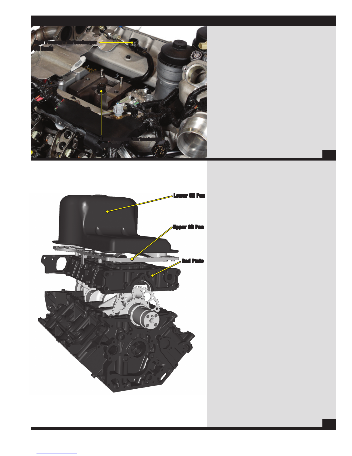
Lubricat i o n S y S t e m
High Pressure Turbocharger
Oil Drain
Low Pressure Turbocharger
Oil Drain
Lower Oil Pan
Turbocharger Oil Drain Tubes
• Oil is supplied to the turbochargers to
lubricate and cool the bearings.
• Each turbocharger has it’s own drain. The high pressure
turbocharger uses a removeable tube where as the low
pressure turbocharger utilizes a small extension tube off
of a machined passage in the turbocharger pedestal.
• The high pressure turbocharger drain tube is sealed
via two (2) O-rings, one at each end of the tube.
• The low pressure turbocharger drain extension
tube is sealed via a rubber coated metal tube.
46
Oil Pan / Bed Plate
• The 6.4L Power Stroke® Diesel uses a two piece oil pan.
The lower half is wider than the bottom of the engine to
increase the oil capacity of the system. Due to this wider
oil pan, an upper oil pan is used to adapt the lower pan to
the bed plate. The upper pan also acts as an oil baffle.
Upper Oil Pan
Bed Plate
• The upper pan is bolted to the bed plate. The bed
plate replaces the individual main bearing caps,
resulting in a more rigid bearing retaining system.
47
27
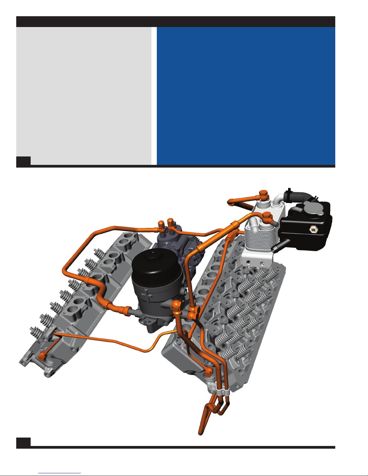
Fuel supply system
Fuel Supply System Features
• The fuel supply system uses a new Horizontal Fuel
Conditioning Module (HFCM). The HFCM filters fuel,
separates water, senses water, and recirculates warm
fuel through the pump during cool fuel conditions.
• The 6.4L Power Stroke® Diesel also uses 2 fuel
filters and a stand alone fuel cooler system.
48
Fuel Supply System Features
• Horizontal Fuel Conditioning Module (HFCM)
• (1) Chassis Mounted 10 Micron Fuel Filter
• (1) Engine Mounted 4 Micron Fuel Filter
• Water Separator
• Fuel Cooler
49
28
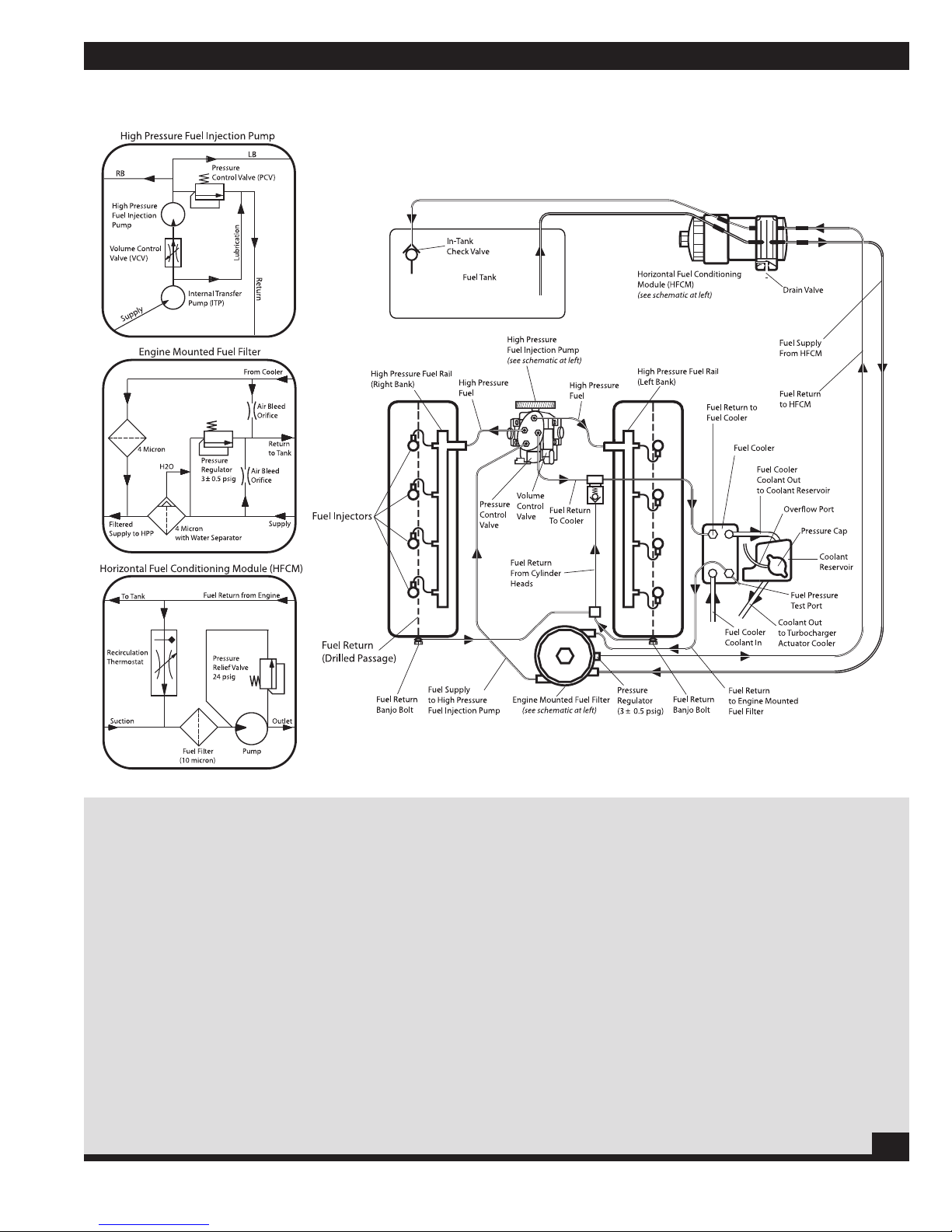
Fuel supply system
Fuel FlOW
Engine Fuel Flow
• The fuel pump, located in the Horizontal Fuel
Conditioning Module (HFCM), draws fuel from the
fuel tank and through a 10 micron fuel filter.
• The HFCM contains the fuel pump, filter, water
separator, water in fuel switch, fuel drain, and
diesel thermo recirculation valve (DTRM).
• The DTRM controls the flow of fuel returned from the engine
mounted filter through the HFCM. If the fuel being drawn from
the fuel tank is cooler than a specified temperature then return
fuel from the engine is recirculated into the inlet of the pump.
• After the fuel is conditioned by the HFCM, the clean pressurized
fuel is sent to the engine mounted fuel filter assembly where
particles larger than 4 micron are filtered out of the fuel.
• The engine mounted fuel filter assembly also regulates fuel
pressure by releasing excess pressure via a return fuel line
back to the HFCM. The engine mounted fuel filter also contains
air bleed orifices to remove air and return it to the tank.
• After the fuel is filtered it is routed to the Internal Transfer Pump (ITP).
• The ITP is located inside the high pressure fuel injection pump
and is used to increase the fuel pressure supplied to the high
pressure fuel injection pump’s three (3) internal pistons.
• After the fuel is pressurized it is routed to the high pressure fuel
rails and to the fuel injectors via high pressure fuel supply tubes.
• A Pressure Control Valve (PCV) located in the outlet side
of the high pressure fuel injection pump controls the fuel
pressure by dumping excess fuel into the fuel return line.
• A Fuel Rail Pressure (FRP) sensor located in the
right side fuel rail monitors the fuel pressure.
• Return fuel from the injectors is routed through a drilled passage
from each cylinder head where it is then united with return fuel
from the high pressure fuel injection pump before being sent
to the fuel cooler and back to the engine mounted fuel filter.
50
29
 Loading...