

Ford 6.0L POWER STROKE Service Procedures And General Diagnostics

''F'' Series
Super Duty

FORWARD
This publication is intended to provide technicians and service personnel with an overview of technical advancements in the
6.0L POWER STROKE Diesel Engine. The information contained in this publication will supplement information contained in
available service literature.
IMPORTANT SAFETY NOTICE
Appropriate service methods and proper repair procedures are essential for the safe,
reliable operation of all motor vehicles, as well as, the personal safety of the individual
performing the work. This manual provides general directions for accomplishing service
repair work with tested, effective techniques. Following the directions will assure
reliability. There are numerous variations in the procedures; techniques, tools, parts for
servicing vehicles and the skill of the individual doing the work. This manual cannot
possibly anticipate all such variations and provide advice or cautions as to each.
Accordingly, anyone who departs from the instructions provided in this manual must first
establish that they do not compromise their personal safety or the vehicle integrity by
their choice of methods, tools or parts.
The following list contains some general WARNINGS that you should follow when you
work on a vehicle.
Always wear safety glasses for eye protection.
Use safety stands whenever a procedure requires you to be under the vehicle.
Be sure that the ignition switch is always in the OFF position, unless otherwise required
by the procedure.
Never perform any service to the engine with the air cleaner removed and the engine
running unless a turbocharger compressor inlet shield is installed.
Set the parking brake when working on the vehicle. If you have an automatic
transmission, set it in PARK unless instructed otherwise for a specific service operation.
If you have a manual transmission, it should be in REVERSE (engine OFF) or
NEUTRAL (engine ON) unless instructed otherwise for a specific service operation.
Operate the engine only in a well-ventilated area to avoid the danger of carbon
monoxide.
Keep yourself and your clothing away from moving parts when the engine is running,
especially the fan, belts, and the turbocharger compressor.
To prevent serious burns, avoid contact with hot metal parts such as the radiator,
turbocharger pipes, exhaust manifold, tail pipe, catalytic converter and muffler.
Do not smoke while working on the vehicle.
To avoid injury, always remove rings, watches, loose hanging jewelry, and loose clothing
before beginning to work on a vehicle. Tie long hair securely behind the head.
Keep hands and other objects clear of the radiator fan blades.

This page intentionally
left blank

6.0L POWER STROKE
3
TABLE OF CONTENTS
OVERVIEW . . . . . . . . . . . . . . . . . . . . . . . . . . . . . . . . .6
Features . . . . . . . . . . . . . . . . . . . . . . . . . . . . . . . . . . . . . . . . . . . . . . . . . . . . . . . . . . . . . . . .6
Horsepower & Torque . . . . . . . . . . . . . . . . . . . . . . . . . . . . . . . . . . . . . . . . . . . . . . . . . . . . . .6
Specifications . . . . . . . . . . . . . . . . . . . . . . . . . . . . . . . . . . . . . . . . . . . . . . . . . . . . . . . . . . . .7
Identification . . . . . . . . . . . . . . . . . . . . . . . . . . . . . . . . . . . . . . . . . . . . . . . . . . . . . . . . . . . . .8
COMPONENT LOCATIONS . . . . . . . . . . . . . . . . . . . . . .9
Features . . . . . . . . . . . . . . . . . . . . . . . . . . . . . . . . . . . . . . . . . . . . . . . . . . . . . . . . . . . . . . .14
COOLING SYSTEM . . . . . . . . . . . . . . . . . . . . . . . . . .17
System Flow . . . . . . . . . . . . . . . . . . . . . . . . . . . . . . . . . . . . . . . . . . . . . . . . . . . . . . . . . . . .17
Water Pump . . . . . . . . . . . . . . . . . . . . . . . . . . . . . . . . . . . . . . . . . . . . . . . . . . . . . . . . . . . .19
LUBRICATION SYSTEM . . . . . . . . . . . . . . . . . . . . . . .21
System Flow . . . . . . . . . . . . . . . . . . . . . . . . . . . . . . . . . . . . . . . . . . . . . . . . . . . . . . . . . . . .21
FUEL SUPPLY SYSTEM . . . . . . . . . . . . . . . . . . . . . . .27
System Flow . . . . . . . . . . . . . . . . . . . . . . . . . . . . . . . . . . . . . . . . . . . . . . . . . . . . . . . . . . . .27
Check Valve . . . . . . . . . . . . . . . . . . . . . . . . . . . . . . . . . . . . . . . . . . . . . . . . . . . . . . . . . . . .30
AIR MANAGEMENT SYSTEM . . . . . . . . . . . . . . . . . . . .31
System Flow . . . . . . . . . . . . . . . . . . . . . . . . . . . . . . . . . . . . . . . . . . . . . . . . . . . . . . . . . . . .31
VGT . . . . . . . . . . . . . . . . . . . . . . . . . . . . . . . . . . . . . . . . . . . . . . . . . . . . . . . . . . . . . . . . . . .34
EGR . . . . . . . . . . . . . . . . . . . . . . . . . . . . . . . . . . . . . . . . . . . . . . . . . . . . . . . . . . . . . . . . . .37
FUEL MANAGEMENT SYSTEM . . . . . . . . . . . . . . . . . .39
High Pressure Oil System . . . . . . . . . . . . . . . . . . . . . . . . . . . . . . . . . . . . . . . . . . . . . . . . . .40
System Flow . . . . . . . . . . . . . . . . . . . . . . . . . . . . . . . . . . . . . . . . . . . . . . . . . . . . . . . . . . . .40
Fuel Injectors . . . . . . . . . . . . . . . . . . . . . . . . . . . . . . . . . . . . . . . . . . . . . . . . . . . . . . . . . . . .43
Stages of Injection . . . . . . . . . . . . . . . . . . . . . . . . . . . . . . . . . . . . . . . . . . . . . . . . . . . . . . .45
ELECTRICAL COMPONENTS . . . . . . . . . . . . . . . . . . .49
Sensors . . . . . . . . . . . . . . . . . . . . . . . . . . . . . . . . . . . . . . . . . . . . . . . . . . . . . . . . . . . . . . . .49
Actuators . . . . . . . . . . . . . . . . . . . . . . . . . . . . . . . . . . . . . . . . . . . . . . . . . . . . . . . . . . . . . . .64
Other Electrical Components . . . . . . . . . . . . . . . . . . . . . . . . . . . . . . . . . . . . . . . . . . . . . . .65
UNIQUE SERVICE PROCEDURES . . . . . . . . . . . . . . . .69
GENERAL DIAGNOSTICS . . . . . . . . . . . . . . . . . . . . . .79
APPENDIX . . . . . . . . . . . . . . . . . . . . . . . . . . . . . . . .83

This page intentionally
left blank

1
Direct Injection
Turbocharged Diesel
Engine
6.0L Power Stroke
• The 6.0L Power Stroke creates 325
horsepower at 3300 RPM and 560 ft/lb of
torque at 2000 RPM.
• Note: Torque has increased and occurs at
lower engine RPM than previous models.
• This publication is not intended to replace
the Service Manual but to introduce the 6.0L
Power Stroke engine.
Horsepower & Torque
Engine Features
6.0L Power Stroke Overview
6.0L POWER STROKE OVERVIEW
6.0L Power Stroke Direct Injection
Turbocharged Diesel Engine
Overview
• Engine Features
• Horsepower & Torque
• Engine Specifications
• Physical ID
• Labeling
2
Engine Features
• Variable Geometry Turbocharger
• Digital Fuel Injection
• 4 Valves per Cylinder
• Reusable Gaskets
• Rear Gear train
• Dual Timing System
3
6
• The 6.0L Power Stroke has been designed
to meet the customers’ expectations of high
horsepower and torque over a wide RPM
range.
• The 6.0L Power Stroke has also been
designed to meet the tougher emissions
standards set by the government.
• Meeting the more stringent customer and
regulated demands are accomplished in part
by: VGT, digital injection system, 4 valves
per cylinder, and dual timing system.
4
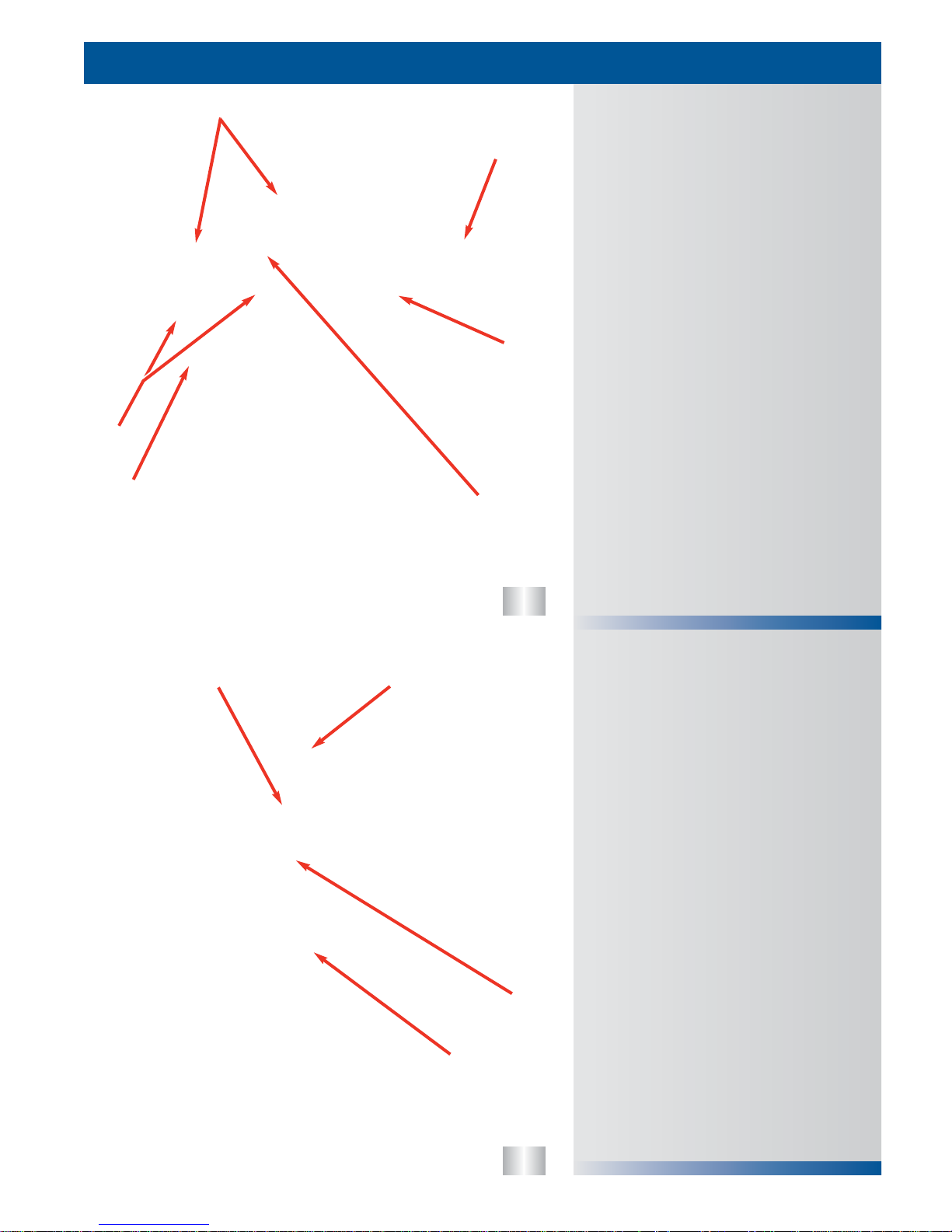
Horsepower & Torque Chart
600
500
400
300
200
100
0
500 1000 1500 2000 2500 3000 3500 4000
engine speed [rpm]
Torque [ft-lb] Pow er [bhp]
6.0L POWER STROKE OVERVIEW
6.0L Power Stroke Diesel Specifications
Engine Type . . . . . . . . . . . . . . . . . . . . . . . . . . . . . . . . . . . . . . . .Diesel, 4-Cycle
Configuration . . . . . . . . . . . . . . . . . . . . . . . . .4 OHV/1 Cam-in-Crankcase-V8
Displacement . . . . . . . . . . . . . . . . . . . . . . . . . . . . . . . . . . . . .365 cu. in (6.0 L)
Bore & Stroke . . . . . . . . . . . . . . . . . . . . . . . . . .3.74 X 4.134 in (95 X 105 mm)
Compression Ratio . . . . . . . . . . . . . . . . . . . . . . . . . . . . . . . . . . . . . . . . .18.0:1
Aspiration . . . . . . . . . . . . . . . . . . . . . . . . . . . . . . . . . . . . . . . . . . . . . .VGT/CAC
Rated Power @ RPM . . . . . . . . . . . . . . . . . . . . . . . . . . . . . . .325 @ 3300 RPM
Peak Torque @ RPM . . . . . . . . . . . . . . . . . . . . . . . . . . . . . . .560 @ 2000 RPM
Engine Rotation, Facing Flywheel . . . . . . . . . . . . . . . . . .Counter Clockwise
Combustion System . . . . . . . . . . . . . . . . . . . . . . . . . .Digital Direct Injection
Total Engine Weight (auto with oil) . . . . . . . . . . . . . . . . . . . .966 lb. (438 kg)
Coolant Flow . . . . . . . . . . . . . . . . . .74.7 gal/min (282.8 L/min) @ 3300 RPM
Air Flow @ RPM . . . . . . . . . . . . . . . . . .732 CFM (20.7 m
3
/min) @ 3300 RPM
Exhaust Flow @ RPM . . . . . . . . . . . . .1499 CFM (42.4 m
3
/min) @ 3300 RPM
Oil Flow @ RPM . . . . . . . . . . . . . . . . . .18.5 gal/min (70 L/min) @ 3300 RPM
Cooling System Capacity (engine only) . . . . . . . . . . . . . . .11.1 qts. (10.5 L)
Lube-System Capacity (including filter) . . . . . . . . . . . . . . . . .15 qts. (14.2 L)
Firing Order . . . . . . . . . . . . . . . . . . . . . . . . . . . . . . . . . . . . . . . .1-2-7-3-4-5-6-8
5
7
• The 6.0L Power Stroke engine is a totally
new engine design that will provide improved
performance, and cleaner emissions.
• The cylinders of the 6.0L Power Stroke are
numbered from the front on the right side
1,3,5,7 and from the front on the left side
2,4,6,8.
Specifications
Front
L
2
R
1
4
6
8
3
5
7

6
7
8
• Another location for the engine serial
number is a label on the FICM (Fuel
Injection Control Module).
• The engine serial number label also states
the build location and build date of the
engine.
• Another label on the FICM is the part
number and the FICM calibration label.
Emissions Label
Serial Number/FICM Calibration Label
Engine Serial Number
6.0L POWER STROKE OVERVIEW
8
• The engine serial number is located on the
left rear corner of the crankcase.
• The engine serial number identifies the
engine family, build location, and the
sequential build number.
• 6.0 - is the engine family identifier.
• HU2U - is a manufacturing designator.
• 6000173 - is a sequential build number.
• States the horsepower rating for the engine,
programmed in the powertrain control
module (PCM).
• Depicts where the engine meets or exceeds
emission standards.
• Shows the engine displacement.
• Is affixed to the right hand valve cover
behind the glow plug control module.

9
10
1) Fuel Supply
2) Fuel Return
3) EBP Sensor and Tube
4) Upper Oil Pan
5) Secondary Fuel Filter
6) EGR Throttle Position Sensor (If Equipped)
1) Thermostat
2) Fuel Inlets on Cylinder Heads
3) Fuel Pressure Regulator
4) ECT Sensor
5) EGR Throttle Actuator (If Equipped)
Left Front of Engine
Front of Engine
COMPONENT LOCATIONS
9
1
2
2
3
5
4
1
2
3
4
5
6

11
12
1) Rocker Arm Carrier
2) Bed Plate
3) Glow Plug Buss Bar
1) FICM
2) CMP Sensor
3) Oil Level Gauge
4) Crankcase Ventilation
Left Rear of Engine
Left of Engine
COMPONENT LOCATIONS
10
1
3
2
1
3
4
2
13
14
Right Rear of Engine
1) Block Heater
2) Turbine Outlet
3) Exhaust Connection to EGR Cooler
4) Exhaust Expansion Joint
1) Exhaust Expansion Joints
2) Heat Shields
3) Lifting “Eye”
4) Serial Number
5) ICP Sensor & IPR (Behind ICP)
Rear of Engine
COMPONENT LOCATIONS
11
1
2
2
3
4
1
3
2
5
4

15
16
1) Heater Return
2) EGR Throttle Actuator
1) CKP Sensor
2) Glow Plug Control Module
Right Front of Engine
Right Side of Engine
COMPONENT LOCATIONS
12
1
2
1
2
17
18
Top of Engine
1) EGR Valve
2) EGR Cooler
3) Turbocharger Compressor Outlet
4) IAT2 Sensor
5) EOP Switch
6) EOT Sensor
1) Oil Filter
2) Turbocharger Oil Supply Line
3) EVRT/VGT Control Valve
4) Injector Connectors
5) Secondary Fuel Filter
6) EGR Cooler Coolant Deaeration Port
Top of Engine
COMPONENT LOCATIONS
13
1
6
5
2
3
4
2
3
4
6
5
1
19
20
21
• The geartrain for the crankshaft, camshaft,
and high pressure pump are located in the
rear of the engine under the rear cover.
• This allows the high pressure pump to be
mounted inside the engine and also reduces
geartrain noise.
Rear Geartrain
Cylinder Head
Rocker Carrier
6.0L POWER STROKE FEATURES
14
• The aluminum rocker arm carrier is mounted
on top of the cylinder head and is held in
place by the cylinder head bolts.
• The rocker arm carrier provides the
mounting location for all of the rocker
fulcrums.
• The carrier also provides the connector pass
through for the injector and glow plug.
• The 6.0L POWER STROKE uses a four (4)
valve per cylinder head design to increase
air flow and efficiency.
• For identification, the exhaust valves are
smaller than the intake valves.
CONNECTOR PASS THROUGH
CONNECTOR PASS THROUGH
CYLINDER HEAD BOLTS
CYLINDER HEAD BOLTS
ROCKER ARMS
ROCKER ARMS
EXHAUST VALVES
INTAKE VALVES
INJECTOR NOZZLE
GLOW PLUG
HIGH PRESSURE PUMP GEAR
HIGH PRESSURE PUMP GEAR
CAMSHAFT GEAR
CRANKSHAFT GEAR
22
23
24
Normal Heat Treatment Discoloration
• The bearing surfaces on the crankshaft are
induction hardened.
• During the hardening process the
surrounding areas of the crankshaft discolor.
This condition is normal.
• A single mass flywheel is used on the
F-450/550 Superduty trucks.
• The single mass flywheel can be identified
by the absence of the above mentioned
parts and that it is machined from one solid
part.
• The 6.0L Power Stroke uses two different
flywheels for the manual transmission.
• A dual-mass flywheel is used on the
F-250/350 Superduty truck.
• The dual-mass flywheel can be identified by
springs located around the flywheel on the
engine side.
• It can also be identified by an extra ring of
bolts on the transmission side of the
flywheel that holds the two masses together.
• From the side it can be identified by the
separation between the clutch surface and
the starter ring.
Single Mass Flywheel
Dual Mass Flywheel
6.0L POWER STROKE FEATURES
15
RING OF BOLTS
CLUTCH SURFACE
STARTER RING
SPRINGS
DISCOLORED AREA
DISCOLORED AREA

16
This page intentionally
left blank

• The modular water pump can be serviced
without disconnecting radiator hoses.
• Both the glow plug sleeves and the injector
sleeves are stainless steel.
Cooling System Features
COOLING SYSTEM
Cooling System Flow
Cooling System Features
• Modular Water Pump
• Stainless Steel Injector Sleeves
• Stainless Steel Glow Plug Sleeves
25
17
26
27
28
29
Cooling System Flow: Oil Cooler
Cooling System Flow: Back of Front
Cover
Cooling System Flow: Front Cover
COOLING SYSTEM
18
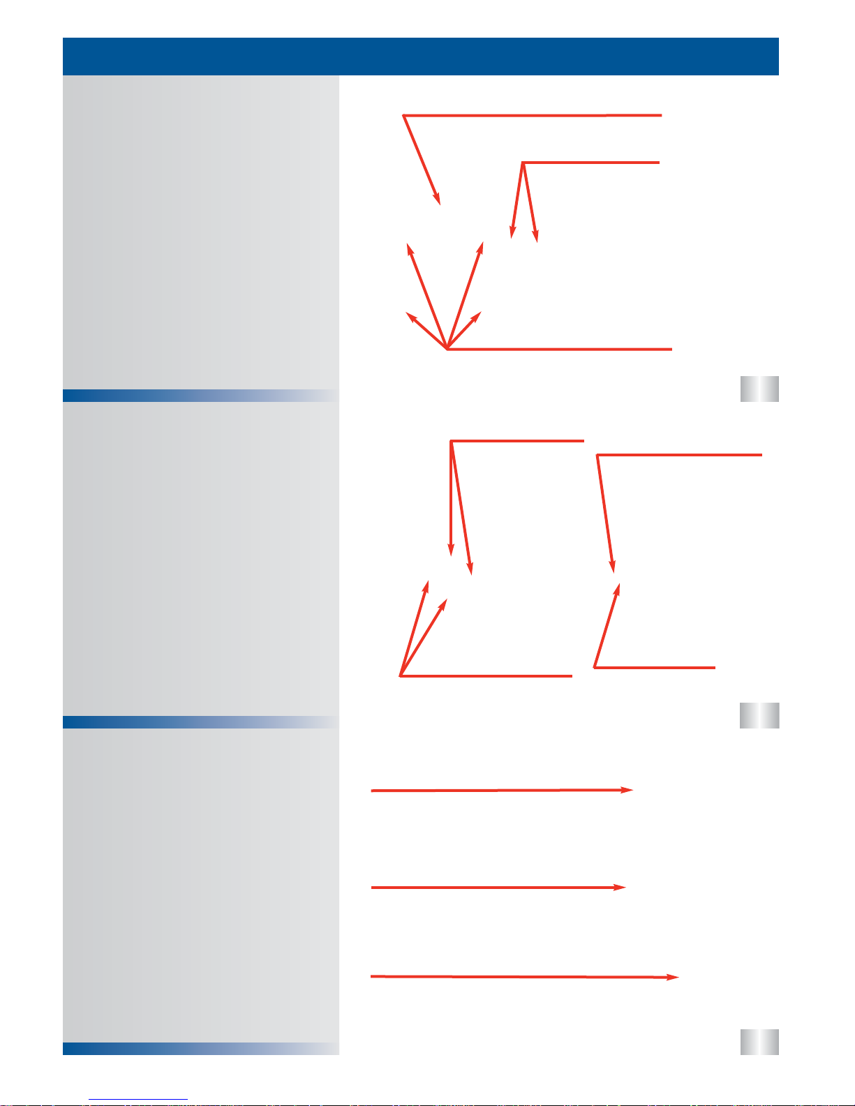
• Coolant is drawn into the inlet of the front
cover and then flows from the water pump
through the front cover to the crankcase.
• Coolant is also routed from the front cover
into the crankcase to a passage that feeds
the oil cooler.
• Return coolant is directed to the thermostat
by the front cover. If the thermostat is open,
coolant flows to the radiator to be cooled. If
the thermostat is closed, coolant is returned
to the water pump via a bypass circuit in the
front cover.
• Coolant is sealed via a silicon in metal one
piece gasket and is directed out of the front
cover through three (3) passages.
• Two of the passages route coolant to the
crankcase to cool the cylinder walls and
cylinder heads.
• The third passage routes coolant to the oil
cooler via a passage in the crankcase.
• There are two passages for coolant to return
from the crankcase into the front cover.
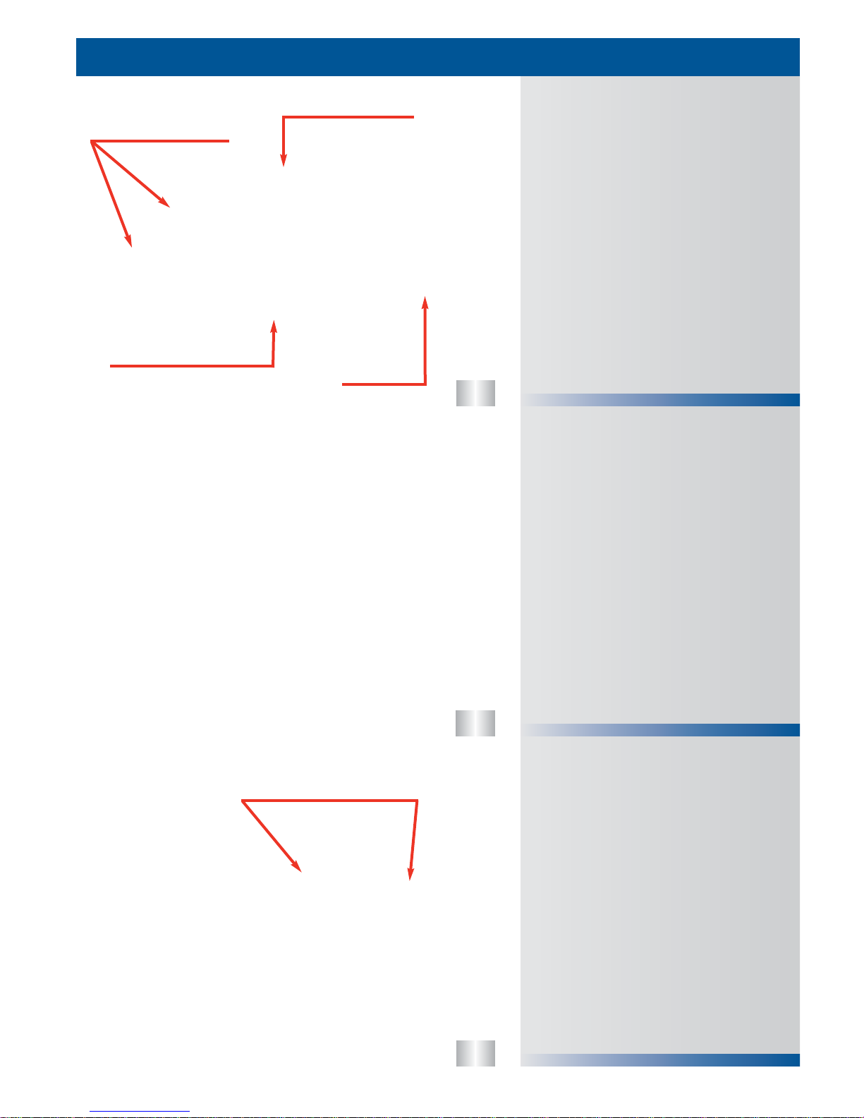
• Coolant is directed out of the crankcase and
into the oil filter base at the front of the
engine.
• The oil filter base routes the coolant into the
front of the oil cooler then toward the back of
the engine.
• Once the coolant has passed through the oil
cooler it is directed out of the oil filter base
to the EGR cooler.
• Note: There are weep holes in the oil filter
base that allow coolant or oil to seep out
side of the filter base if an oil cooler seal
is damaged.
IN
IN
IN
IN
OUT
OUT
OUT
OUT
30
31
32
Injector Sleeve
Water Pump & Front Cover
Cooling System Flow: EGR Cooler
COOLING SYSTEM
19
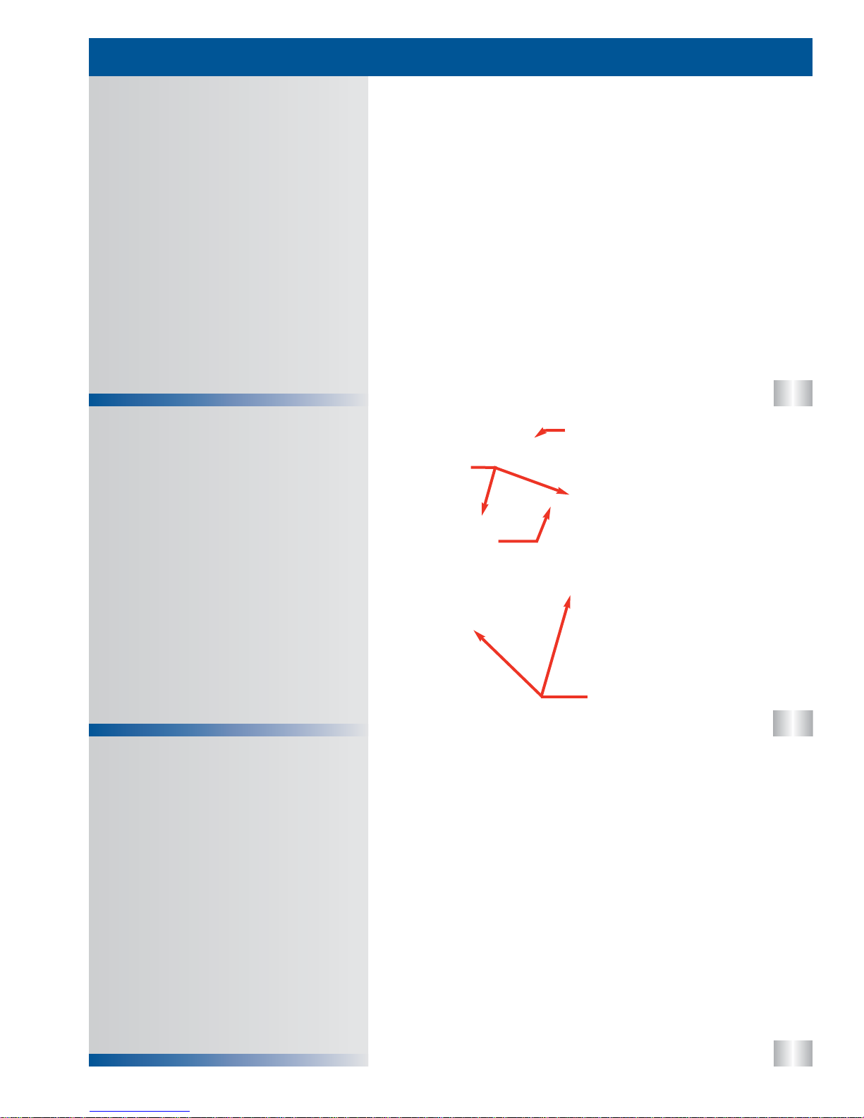
• Coolant flows out of the filter base and into
the EGR cooler through a tube that directs
the coolant to the back of the EGR cooler.
• Coolant flows through the EGR cooler and
removes heat from the exhaust gasses
before the exhaust arrives at the EGR valve.
• Coolant exits the front of the EGR cooler and
enters the coolant passage of the intake
manifold. The intake manifold directs the
coolant back into the front cover.
• The water pump, (hub and impeller) is
mounted into the front cover which is the
housing for the water pump.
• The water pump impeller pulls coolant from
the center of the housing and pushes it
outward.
• The water pump has a built in reservoir to
catch small amounts coolant that during
normal operation of the engine may seep
past the seal.
• Note: The water pump impeller may be
damaged if dropped or hit by a hard
object.
• The 6.0L Power Stroke uses stainless steel
injector sleeves to seal coolant from the
injector and to transfer heat from the injector
to the coolant.
• The injector sleeve is replaceable. See
unique service procedures or service
manual for more details.
IMPELLER
IMPELLER
RESERVOIR
RESERVOIR
INJECTOR SLEEVE
INJECTOR SLEEVE

33
34
• The coolant recovery bottle is located above
the left valve cover.
• One of the ports on the bottle is attached to
the EGR cooler deaeration port. If this port
or hose is blocked, damage could occur to
the EGR cooler.
Coolant Recovery Bottle
Glow Plug Sleeve
COOLING SYSTEM
20
• Glow plug sleeves are used to keep coolant
from coming in direct contact with the glow
plugs and to seal coolant from the
combustion chamber.
• The glow plug sleeve is replaceable. See
unique service procedures or the service
manual for more details.
GLOW PLUG SLEEVE
GLOW PLUG SLEEVE
COOLANT RECOVERY BOTTLE
COOLANT RECOVERY BOTTLE
TO EGR COOLER
TO EGR COOLER
36
System Flow
Lubrication System Features
LUBRICATION SYSTEM
• The 6.0L Power Stroke uses an oil cooler
that is mounted in the valley of the engine
under the oil filter. There is also a oil
pressure test port in the front of the oil
cooler.
• There are no oil passages located on the
outside of the crankcase. This reduces the
chance for oil leaks.
• The oil filter is a canister style filter mounted
on the top of the engine, that drains to the
oil pan during servicing.
• The gerotor oil pump and oil pressure
regulator are both located in the front of the
engine behind the vibration damper.
Lubrication System Features
• Integrated Oil Cooler
• No External Oil Passages in Crankcase
• Easy Access Canister Style Oil Filter
• Front Oil Pressure Test Port
• External Oil Pressure Regulator
35
21
OIL FILTER BASE
GEROTOR OIL PUMP
OIL PRESSURE
REGULATOR
Oil Pump
Oil Cooler
Oil Filter
Pump
Bypass
70 PSI
Cooler
Bypass
25 PSI
Filter
Bypass
20 PSI
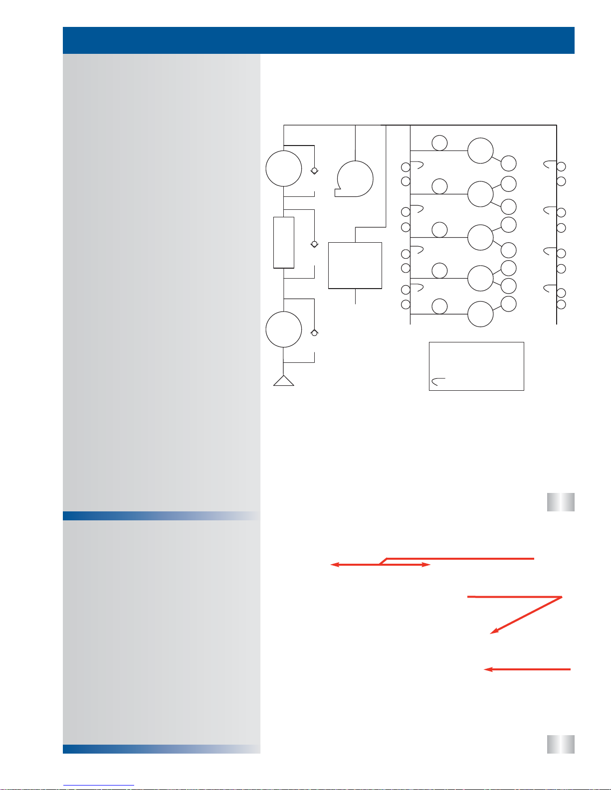
Lube Pressure Oil System Schematic
T
T
T
T
T
T
T
T
T
T
T
T
T
T
T
T
MB
MB
MB
MB
MB
CB
CB
CB
CB
CB
Turbo
CR
CR
CR
CR
CR
CR
CR
CR
Oil Reservoir
for High
Pressure
Pump 0.95 Qt.
To High
Pressure Oil
System
T= Tappet
CB = Cam Bearing
MB = Main Bearing
CR= Connecting Rod
= Piston Cooling Jet
Right Bank
Left Bank
37
38
Oil Pan / Bed Plate
Lubrication System Oil Flow
LUBRICATION SYSTEM
22
• Oil is drawn from the oil pan through the
pick-up tube to the gerotor oil pump.
• The oil pressure is regulated to 75 psi via
the oil pressure regulator relieving excessive
oil pressure to the inlet of the oil pump.
• From the oil pump, oil is directed to the oil
cooler and then the to the oil filter.
• From the oil filter the oil is supplied to four
(4) passages. One is to the turbocharger for
lubrication and VGT control via an external
line.
• The oil also is provided to the oil reservoir
that supplies the high pressure oil pump.
• The two (2) other passages are to the tappet
oil feed on the right and left banks. The
tappet galleries also provide oil to the piston
cooling jets.
• Cross drillings off of the right bank tappet
gallery feed the cam bearings, then the
crankshaft main bearings.
• The crankshaft has cross drillings in it to
direct oil to each of connecting rod bearings.
• The 6.0L Power Stroke uses a two piece oil
pan. The lower half is wider than the bottom
of the engine to increase its capacity. Due to
this wider oil pan, an upper oil pan is used to
adapt the lower pan to the bed plate. The
upper pan also acts as an oil baffle.
• The upper pan is bolted to the bed plate.
The bed plate replaces the individual main
bearing caps. This one piece design results
in a more rigid bearing retaining system.
• The pick-up tube is bolted to the upper pan
and oil is routed through the upper pan and
the bed plate to the front cover.
WIDER OIL PAN
UPPER OIL PAN
BED PLATE
39
40
41
Gerotor Oil Pump
Oil Pressure Regulator
Pick-up Tube / Oil Aeration
LUBRICATION SYSTEM
23
• The pick-up tube supplies oil from the oil pan
to the oil pump.
• The pick-up tube is sealed to the upper oil
pan utilizing an o-ring. If the o-ring is
damaged or missing, it could cause oil
aeration and poor performance.
• Oil aeration is the result of air being
introduced to the lubrication system on the
suction side of the system or by the
breakdown of the anti foaming agents in the
oil. Oil aeration can cause low power and
poor idle.
• A damaged or loose pick-up tube could also
cause oil aeration.
• The oil pressure regulator is located in the
front cover just below the gerotor oil pump.
• The oil pressure regulator is calibrated to
open at pressures above 75 psi. It should be
closed below that pressure.
• The gerotor oil pump is driven off of the flats
on the nose of the crankshaft.
• The pump is designed to flow the large
volume of oil required for the 6.0L POWER
STROKE.
• The gerotor oil pump front cover is located
by two (2) dowel pins in the crankcase front
cover, and is sealed by a press in place
gasket.
• The outer housing for the oil pump is
designed into the crankcase front cover.
O-RING
O-RING
UPPER OIL PAN
UPPER OIL PAN
OIL PICK-UP TUBE
OIL PICK-UP TUBE
OIL PUMP
OIL PUMP
OIL PRESSURE REGULATOR
REGULATOR HOUSING
DOWEL
DOWEL
DOWEL
DOWEL
OUTER GEAR
OUTER GEAR
INNER GEAR
INNER GEAR
CRANKSHAFT
CRANKSHAFT
42
43
44
Oil Cooler Housing & Filter Base
Oil Cooler
Front Cover
LUBRICATION SYSTEM
24
• Oil flows from the crankcase to the oil pump
via a passage in the back of the front cover.
• When the oil pump is turned by the
crankshaft it creates oil pressure and
pushes oil through one of two passages.
One passage is to the oil cooler and the
other is through the oil pressure regulator
back to the oil pump inlet.
• All of the passages from the front cover to
the crankcase are sealed with a silicon in
metal, one piece gasket.
• The oil cooler is mounted in the valley of the
engine and uses engine coolant to dissipate
heat from the engine oil.
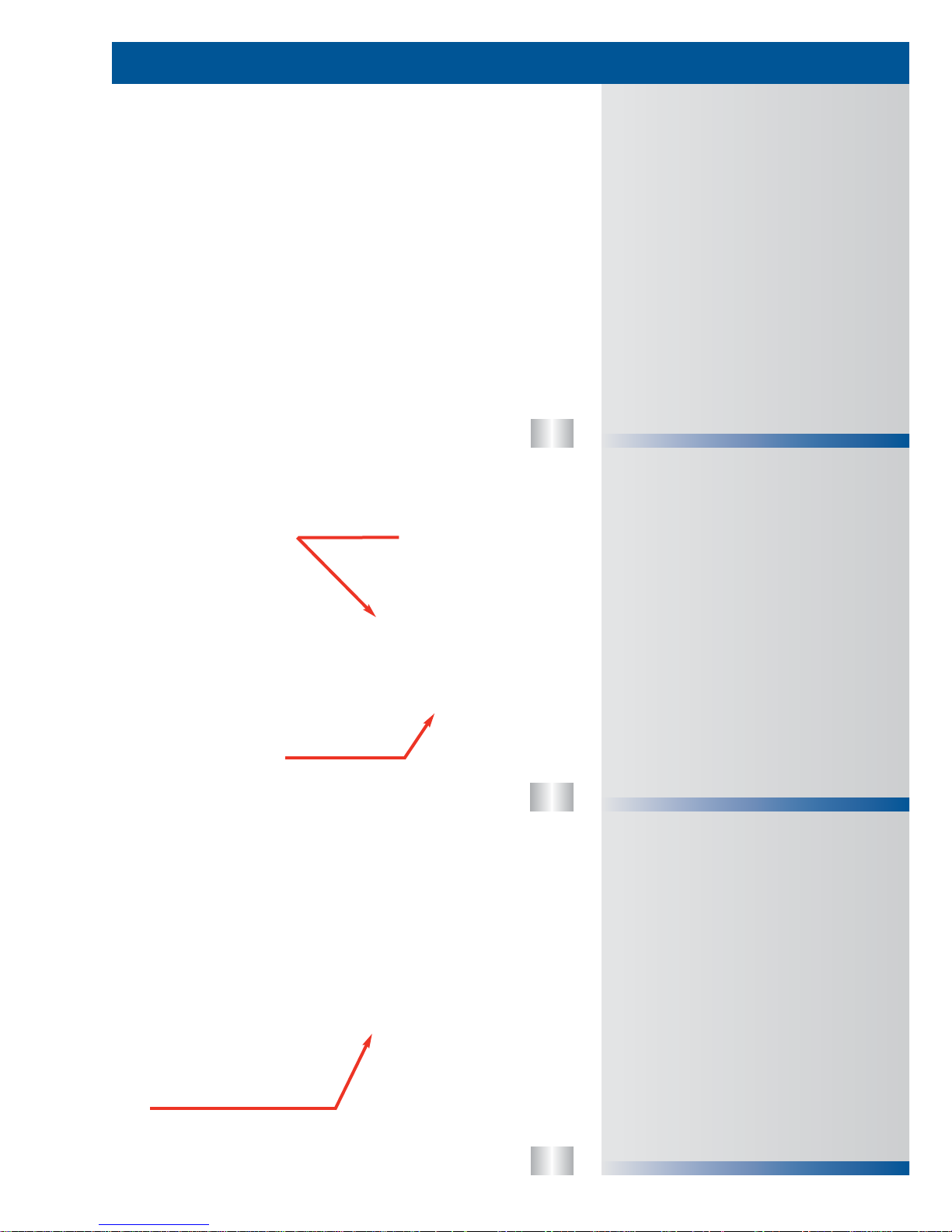
• Oil passes from the rear of the cooler to the
front, while coolant passes from the front of
the cooler to the rear.
• The coolant and oil are separated by
multiple plates that create passages in the
oil cooler.
• Note: If the oil cooler is damaged it could
cause contamination of the lubrication
and cooling systems.
• The oil cooler housing has passages in it to
direct the flow of coolant and oil.
• Oil is routed from the front of the crankcase
to the back of the housing where it enters
the oil cooler. The oil passes from the rear of
the oil cooler to the front of the cooler and is
cooled in the process. The oil is then sent to
the oil filter through the oil filter base.
Filtered oil is sent to the oil reservoir for the
high pressure pump and the oil passages in
the crankcase.
• The coolant is directed from the front of the
crankcase to the front of the oil cooler. It
then passes through the oil cooler and cools
the oil. As the coolant exits the rear of the oil
cooler it is directed to the EGR cooler.
RETURN TO OIL PUMP
RETURN TO OIL PUMP
OIL FLOW TO OIL COOLER
OIL FLOW TO OIL COOLER
ONE PIECE GASKET
ONE PIECE GASKET
OIL PRESSURE
TEST PORT
OIL COOLER
OIL COOLER
TO RESERVOIR & CRANKCASE
COOLANT FROM WATER PUMP
COOLANT TO
OIL COOLER
OIL TO
OIL COOLER
OIL FROM
OIL PUMP
COOLANT FROM
OIL COOLER
OIL TO
OIL FILTER
45
46
47
Oil Reservoir & Screen
Oil Filter
Oil Filter Base & Valves
LUBRICATION SYSTEM
25
• The oil reservoir for the high pressure oil
pump is located under the oil cooler in the
valley of the engine.
• The oil reservoir holds about 1qt of oil.
• A screen in the oil reservoir catches any
large debris that may be in the oil before it
gets to the high pressure oil pump.
• The 6.0L POWER STROKE uses a cartridge
style oil filter, located on the top of the
engine.
• When the oil filter is removed, the oil filter
housing drain valve is automatically opened
to drain most of the oil from the housing.
• The oil filter element snaps into the oil filter
lid.
• Note: The oil filter lid should be removed
before draining the oil from the oil pan so
that the oil can drain from the filter
housing into the oil pan.
• The oil filter base routes oil to the oil filter,
engine oil pressure switch (EOP), engine oil
temperature sensor (EOT), and the
turbocharger oil feed.
• The oil filter base also houses the anti-drainback check valve that keeps oil in the oil
filter assembly after the engine is shut off.
• The oil cooler bypass is in the filter base and
opens at a pressure differential of 25 psi.
• The oil filter bypass is in the oil filter stand
pipe and opens at a pressure differential of
20 psi.
• There is an oil drain for the filter housing to
drain oil from the housing during an oil
change.
OIL TEMPERATURE SENSOR
OIL PRESSURE SWITCH
OIL PRESSURE SWITCH
OIL COOLER BYPASS
ANTI DRAIN BACK
OIL FILTER DRAIN
OIL FILTER BYPASS
OIL FILTER BYPASS
OIL FILTER ELEMENT
OIL RESERVOIR SCREEN
OIL RESERVOIR SCREEN
48
49
50
• The VGT uses oil to control the turbocharger
and to lubricate the bearings.
• After oil passes through the turbocharger
center section, it is sent back to the
crankcase via a turbo oil drain tube.
• The turbo oil drain tube is located under the
turbocharger and is sealed with two (2)
o-rings, one fits into the turbocharger and
the other goes to the high pressure oil pump
cover.
Turbocharger Oil Drain Tube
Turbocharger Oil Supply & VGT
Control
Oil Flow at Oil Reservoir
LUBRICATION SYSTEM
26
• There are five (5) oil passages and one
coolant passage near the oil reservoir in the
crankcase.
• Two (2) of the oil passages are for oil feed to
the crankcase for lubrication.
• One (1) is for oil feed to the oil cooler and
the other oil passage is oil filter drain to the
oil pan.
• The passage in the bottom of the reservoir is
for oil feed to the high pressure oil pump.
• The coolant passage is for coolant feed from
the water pump to the oil cooler.
• Oil is supplied to the turbocharger from the
oil filter base via a flexible steel braided oil
line to the top of the turbocharger.
• The oil line is connected to the oil filter base
using a snap to connect fitting and requires
a special tool for removal.
• This line is also the feed to the VGT control
valve.
PRESSURE PUMP
PRESSURE PUMP
OIL FEED TO HIGH
OIL FEED TO HIGH
OIL FILTER DRAIN TO PAN
OIL COOLER
OIL FEED TO
OIL COOLER
OIL FEED TO
BANK TAPPET
TO LEFT
GALLERY
BANK TAPPET
TO LEFT
GALLERY
COOLANT
GALLERY
FEED TO OIL
COOLER
COOLANT
FEED TO OIL
COOLER
BANK TAPPET
TO RIGHT
GALLERY
BANK TAPPET
TO RIGHT
FRONT OF ENGINE
FRONT OF ENGINE
OIL SUPPLY
OIL SUPPLY
VGT CONTROL VALVE
VGT CONTROL VALVE
HIGH PRESSURE PUMP COVER
HIGH PRESSURE PUMP COVER
DRAIN TUBE O-RINGS
DRAIN TUBE O-RINGS
• The fuel supply system uses a new
Horizontal Fuel Conditioning Module
(HFCM). The HFCM filters fuel, separates
water, senses water, heats fuel, and
recirculates warm fuel through the pump
during cool fuel conditions.
• The 6.0L Power Stroke also has a secondary
fuel filter.
• There is a check valve in the front of each
cylinder head that does not allow fuel to
return to the fuel supply system. This type of
system is called a dead-end fuel system.
Fuel Supply System Features
FUEL SUPPLY SYSTEM
52
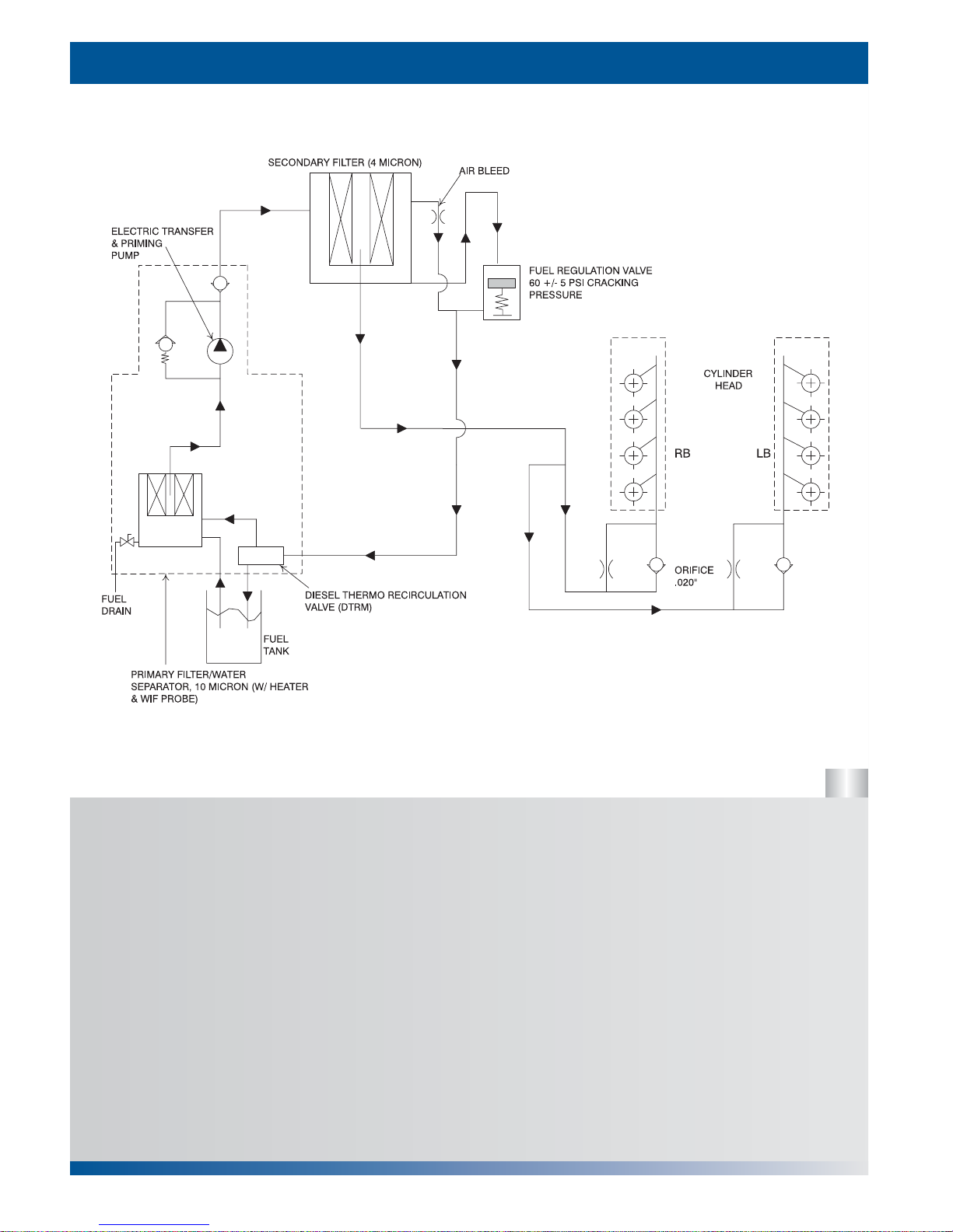
Engine Fuel System Flow
27
Fuel Supply System Features
• Horizontal Fuel Conditioning Module
(HFCM)
• Secondary Fuel Filter
• Fuel Check Valves
51
FUEL SUPPLY TO HEADS
FUEL RETURN
TO TANK
FUEL SUPPLY
FROM PUMP
FUEL CHECK VALVES
FUEL FILTER
53
FUEL SUPPLY SYSTEM
28
Engine Fuel Flow
• After the fuel is conditioned by the
HFCM, the clean pressurized fuel is
sent to the secondary fuel filter
assembly where particles larger
than 4 micron are filtered out of the
fuel.
• The secondary filter assembly also
regulates fuel pressure by releasing
excess pressure via a return fuel
line back to the HFCM.
• It also has an orifice at the top of
the housing in order to bleed air out
of the housing and back to the fuel
tank.
• After the fuel flows through the
secondary filter it is directed to the
two (2) cylinder heads via fuel lines
past the fuel check valves.
• The fuel is directed to the injectors
via passages that are drilled into
the cylinder heads.
• Once the fuel has entered the head
past the check valve, it does not
return to the fuel supply system.
This is called a dead-end fuel
system.
• The fuel pump, located in the
Horizontal Fuel Conditioning
Module (HFCM), draws fuel from
the fuel tank and through a 10
micron fuel filter.
• The HFCM contains the fuel pump,
filter, water separator, water in fuel
switch, fuel drain, fuel heater, and
diesel thermo recirculation valve
(DTRM).
• The DTRM controls the flow of fuel
returned from the secondary filter
through the HFCM. If the fuel being
drawn from the fuel tank is cool
then return fuel is recirculated into
the pump, if it is warm then return
fuel is sent to the fuel tank
54
55
• Fuel is drawn into the HFCM from the fuel
tank via a supply line.
• If the temperature of the the fuel is below
50°F (10°C) it is heated by the fuel heater.
The fuel heater shuts off at 80°F (27°C).
• After being heated, fuel enters the filter
housing via a one-way check valve.
• Once in the filter housing, water is separated
from the fuel. If large amounts of water are
found in the fuel, a sensor in the separator
warns the operator of this condition by
illuminating a light on the dash.
• Fuel is then drawn through the 10 micron
fuel filter and into the fuel pump.
• Conditioned pressurized fuel is then supplied
to the engine mounted fuel filter via a fuel
supply line. The pump has an internal
regulator that limits fuel pressure to 100psi.
• Fuel returning from the pressure regulator on
the engine mounted fuel filter comes into the
HFCM and a DTRM either allows the fuel to
return to the tank or returns it to the
unfiltered side of the fuel filter in the HFCM.
The DTRM starts to open (recirculating fuel
back into the pump) at 80°F (27°C) and is
fully open at 50°F (10°C).
• The HFCM is mounted to the frame rail on
the drivers side.
• The HFCM is a single module that performs
multiple tasks. It heats fuel, separates water
from the fuel, senses when water is present
in the fuel, filters particulates from the fuel,
creates fuel pressure needed to to supply
fuel to the engine mounted fuel filter
• A DTRM (Diesel Thermo Recirculation
Module) is also part of the HFCM. It
recirculates fuel that returns from the engine
mounted fuel filter back into the fuel filter
instead of back to the tank, which in cool
fuel conditions.
HFCM (Horizontal Fuel Conditioning
Module) Fuel Flow
HFCM (Horizontal Fuel Conditioning
Module)
FUEL SUPPLY SYSTEM
29
56
WATER IN FUEL
WATER IN FUEL
FUEL PUMP POWER
FUEL PUMP POWER
FUEL SUPPLY TO HFCM
FUEL SUPPLY TO HFCM
FUEL RETURN TO TANK
FUEL RETURN TO TANK
FUEL RETURN TO HFCM
FUEL RETURN TO HFCM
FUEL HEATER
FUEL HEATER
FUEL SUPPLY TO ENGINE
FUEL SUPPLY TO ENGINE
DTRM
WIF SENSOR
WIF SENSOR
FUEL HEATER
FUEL PUMP
FUEL FILTER
THROUGH FILTER INTO PUMP
 Loading...