

Page 1
DO NOT DESTROY: THIS MANUAL IS REQUIRED BY
LAW. KEEP UNTIL THE VEHICLE IS COMPLETED BY
THE FINAL STAGE MANUFACTURER.
2005
E-SERIES
INCOMPLETE VEHICLE MANUAL
Incomplete Vehicle Types
For This Manual
INCOMPLETE
E-SERIES
VANS &
WAGONS
E-SERIES
CUTAWAY
E-SERIES
BASIC
CHASSIS
Ð
May, 2004
5C2S-19A268-AA
Page 2

U.S. & CANADA MOTOR VEHICLE SAFETY STANDARDS
(APPLICATION BY VEHICLE TYPE)
Bus (Not Truck Truck
Standard School School (Not (Walk-in (1)
Number Title of Standard Bus) Bus Walk-In Van) MPV Van) Equip.
101 Control Location, Identication and Illumination X X X X X
102 Transmission Shift Lever Sequence, Starter
Interlock & Transmission Braking Effect X X X X X
103 Windshield Defrosting & Defogging Systems X X X X X
104 Windshield Wiping and Washing Systems X X X X X
105 Hydraulic and Electric Brake Systems X X X X X
106 Brake Hoses X X X X X X
108 Lamps, Reective Devices & Associated Equipment X X X X X X
108.1 Headlamps (Canada only) X X X X X X
110 Tire Selection and Rims (U.S. only) X X X X X X
111 Rearview Mirrors X X X X X
113 Hood Latch Systems X X X X X
114 Theft Protection X(2) X(2)
115 Vehicle Identication Number (Canada only) X X X X X
116 Hydraulic Brake Fluids X X X X X X
118 Power Operated Window, Partition, and Roof
Panel Systems X(2) X(2) X(2)
119 New Pneumatic Tires for Vehicles Other
Than Passenger Cars X
120 Tire Selection and Rims for Motor Vehicles
Other Than Passenger Cars X X X X X X
124 Accelerator Control Systems X X X X X
131 School Bus Pedestrian Safety Devices (except
Multifunction School Activity Bus) X
135 Light Vehicle Brake Systems X(10) X(10) X(10) X(10) X(10)
201 Occupant Protection in Interior Impact X(2)(9) X(2)(9) X(2) X(2) X(2)(9)
202 Head Restraints X(2) X(2) X(2) X(2) X(2)
203 Impact Protection for the Driver from the
Steering Control System X(2) X(2) X(2) X(2)
204 Steering Control Rearward Displacement X(3) X(3) X(3) X(3)
205 Glazing Materials X X X X X X
206 Door Locks and Door Retention Components X X X
207 Seating System X X X X X
208 Occupant Crash Protection X(5)(6) X(5)(6) X(5)(6) X(5)(6) X(5)(6) X
209 Seat Belt Assemblies X X X X
210 Seat Belt Assembly Anchorages X X X X X
210.1 User-Ready Tether Anchorages for Restraint
Systems (Canada only) X X X X
210.2 Lower Universal Anchorage Systems for Restraint
Systems and Booster Cushions (Canada only) X X X X
212 Windshield Mounting X(2) X(2) X(2) X(2)
213 Child Restraint Systems X X X X X X
214 Side Impact Protection X(2)(7) X(2) X(2)(7) X(2)(7)
217 Bus Window Retention and Release X X
219 Windshield Zone Intrusion X(2) X(2) X(2) X(2)
(Continued on Page 1)
E-SERIES (May, 2004)
Page 3
U.S. & CANADA MOTOR VEHICLE SAFETY STANDARDS
(APPLICATION BY VEHICLE TYPE)
(Continued from Inside Front Cover)
Bus (Not Truck Truck
Standard School School (Not (Walk-in (1)
Number Title of Standard Bus) Bus Walk-In Van) MPV Van) Equip.
220 School Bus Rollover Protection X
221 School Bus Body Joint Strength X
222 School Bus Passenger Seating and Crash
Protection X
225 Child Restraint Anchorage Systems (U.S. only) X(8) X(8) X(8) X(8) X(8)
301 Fuel System Integrity X(2) X X(2) X(2) X(2)
302 Flammability of Interior Materials X X X X X
PART Vehicle Identication Number (U.S. only) X X X X X
565.4
1106 Noise Emissions (Canada only) X X X X X
(1) Applicable to Equipment for use on applicable vehicle types.
(2) Applicable to vehicles with a GVWR of 4536 kg [10,000 lb]
or less.
(3) Applicable to vehicles with a GVWR of 4536 kg [10,000 lb]
or less and an unloaded vehicle weight of 2495 kg [5500 lb]
or less.
(4) Applicable to vehicles with a GVWR of 2722 kg [6000 lb] or
less.
(5) Injury criteria required for vehicles with a GVWR of 3856 kg
[8500 lb] or less and an unloaded vehicle weight of 2495 kg
[5500 lb] or less except, in U.S., walk-in van-type trucks and
vehicles designed to be sold exclusively to the U.S. Postal
Service and, in Canada, vehicles manufactured for operation
by persons with disabilities.
(6) Injury criteria is optional for some vehicles where not required.
(7) Dynamic Performance Requirements apply to MPV, truck or a
bus with a GVWR of 2722 kg [6000 lb] or less.
(8) Tether anchors and latch/ISO Fix lower anchors that are installed
voluntarily or by regulation must comply with this Standard.
(9) The requirements of section S6 of Standard Number 201 (United
States) do not apply to buses with a GVWR more than 3860 kg
[8510 lb] and walk-in van type trucks.
(10) Applicable to vehicles with a GVWR of 3500 kg [7716 lb] or
less.
E-SERIES (May, 2004) 1
Page 4

E-SERIES (May, 2004) 3
INTRODUCTION
Information in this manual is furnished pursuant to United States and Canadian
safety regulations or, in some cases where the information is not required by
regulation, is furnished for the convenience of intermediate or nal stage vehicle
manufacturers. Incomplete vehicles manufactured for sale or importation into
the U.S., are specially equipped for the United States. The descriptions and
statements contained in the manual relate only to motor vehicle safety standards
issued under the National Trafc and Motor Vehicle Safety Act of 1966 as
amended.
An incomplete vehicle manufactured for sale or importation into Canada is
specially equipped for Canada. This vehicle conforms to the applicable Canadian
Motor Vehicle Safety Standards (CMVSS) on the date of manufacture printed on
the cover of this manual. Requirements unique to vehicles for use in Canada are
identied in the Statements of Conformity and the “Canadian Vehicles”, page 48.
The Emission Certication Information section of this manual contains information
regarding conformity to exhaust emission regulations of the United States,
Canada, and the State of California and fuel economy regulations of the United
States.
This manual should not be relied upon with respect to compliance with any
regulation of the Federal Highway Administration or regulations issued pursuant
to the Occupational Safety and Health Act (OSHA) or any other federal,
state, or local regulations governing the performance or construction of motor
vehicles (except for those requirements shown under the headings “Unleaded
Gasoline Label,” page 49, “Warranty and Maintenance,” page 50, and “Emission
Control Information Label,” page 50). It is the responsibility of the nal stage
manufacturer to determine applicability and comply with any federal, state, or
local requirements not detailed in this manual.
IMPORTANT:
UNITED STATES VEHICLES
Ford Motor Company has endeavored, whenever possible, to state the specific
conditions under which an incomplete vehicle may be completed to conform to each
applicable Federal Motor Vehicle Safety Standard. These specic statements are
intended to aid subsequent stage manufacturers in avoiding instances of inadvertent
noncompliance to particular standards.
Note that the nal responsibility for the compliance of the completed vehicle rests with
the nal stage manufacturer who is required by law to certify, as prescribed by Section
567.5 of Title 49, Code of Federal Regulations, that the completed vehicle conforms to
all applicable Federal Motor Vehicle Safety Standards and that all applicable federal,
state and California emission/noise standards are conformed with.
Ford Motor Company does not make any representation as to the appropriateness
of modications for any particular application other than expressly stated herein.
Intermediate and nal stage manufacturers must exercise proper engineering judgment
to determine if a modication is appropriate for their specic application.
IMPORTANT:
UNITED STATES AND CANADIAN VEHICLES
Alterations to an incomplete vehicle by someone other than Ford Motor Company, or
damage in transit, may affect compliance statements that are furnished in this manual,
or representations that are printed on the label that may be afxed to a vehicle.
INTRODUCTION
E-SERIES (May, 2004)2
Page 5

TABLE OF CONTENTS
DEFINITIONS .................................................................................... 4-5
GENERAL INFORMATION .................................................................... 6
Directions........................................................................................... 6
VEHICLE DESCRIPTION ..................................................................... 7
COMPLETED VEHICLE TYPES .............................................................8
STATEMENTS OF CONFORMITY................................................... 9-47
CANADIAN VEHICLES
Vehicle Identication ........................................................................ 48
Daytime Running Lamp (DRL)......................................................... 48
Canadian Radio Frequency Interference (RFI)................................ 48
EMISSION CERTIFICATION INFORMATION
Medium Duty Passenger Vehicles (MDPV).......................................49
Frontal Area and Weight Restrictions ...............................................49
High Altitude Requirements..............................................................49
Emission Control Hardware ..............................................................49
Unleaded Gasoline Label ................................................................ 49
Exterior Noise .................................................................................. 50
Tampering with Noise Controls .........................................................50
Warranty and Maintenance.............................................................. 50
Evaporative Emissions..................................................................... 50
Malfunction Indicator Light (MIL) ..................................................... 50
Ozone Depleting Substance (ODS)..................................................50
Emission Control Information Label................................................. 50
California Fuel Vapor Recovery ....................................................... 51
California Motor Vehicle Emission Control Label ............................. 51
Radio Frequency Interference (RFI) ................................................ 51
SUPPLEMENTS .................................................................................. 52
REFERENCE INFORMATION ............................................. Back Cover
E-SERIES (May, 2004) 3
TABLE OF CONTENTS
Page 6

DEFINITIONS
The following denitions are from Title 49, Code of Federal Regulations, Parts 567.3, 568.3 and 571.3 where
noted. Canadian denitions are from Canada Motor Vehicle Safety Regulations, Section 2(1), and are in italics.
Ford Motor Company denitions are for the purpose of this manual only. Some terms are followed by an
abbreviation that is used throughout this manual.
Ambulance – is a vehicle for emergency medical care which
provides: A driver’s compartment; a patient compartment
to accommodate an Emergency Medical Technician (EMT),
Paramedic, and two litter patients (one patient on the
primary cot and secondary patient on folding litter located
on the squad bench) so positioned that the primary patient
can be given intensive life-support during transit; equipment
and supplies for emergency care at the scene as well as
during transport; two-way radio communication; and, when
necessary, equipment for light rescue/extrication procedures.
The Ambulance shall be designed and constructed to afford
safety, comfort, and avoid aggravation of the patient’s injury
or illness. (From Federal Specication KKK-A-1822-E).
Ford Motor Company also includes within its denition
of ambulance any vehicle that is used for transporting
life-support equipment, for rescue operations, or for nonemergency patient transfer if the engine of the vehicle is
equipped with a “throttle kicker” device, which enables an
operator to increase engine speed over normal idle speed
when the vehicle is not moving.
B-Pillar – is the vehicle body structure located directly
rearward of each front door. This structure will include
the outer panel, all inner panels or reinforcements which
support the door opening, the door latching system, and/or
the roof structure. (Ford Motor Company)
Basic (Stripped) Chassis – an incomplete vehicle, without
occupant compartment, that requires the addition of
an occu pant compartment and cargo-carrying, work
performing, or load-bearing components to perform its
intended function. (Ford Motor Company)
Bu s – a motor veh icle with motive po wer, exce pt a
trailer, designed for carr ying more than 10 persons.
(49CFR571.3)
Bus (Canada) – a vehicle having a designated seating capacity
of more than 10, but does not include a trailer or a vehicle
imported temporarily for special purposes. (autobus)
Chassis Cab – an incomplete vehicle, with completed occupant
compartment, that requires only the addition of cargocarrying, work performing, or load-bearing components to
perform its intended functions. (49CFR567.3)
Completed Vehicle – a vehicle that requires no further
manufacturing operations to perform its intended function,
other than the addition of readily attachable components,
such as mirrors or tire and rim assemblies, or minor
nishing operations such as painting. (49CFR568.3)
Critical Control Item – is a component or procedure which
may affect compliance with a federal regulation or, which
could directly affect the safe operation of the vehicle.
The identifying symbol is an inverted delta ( ). (Ford
Motor Company)
Cutaway Chassis – an incomplete vehicle that has the back
of the cab cut out for the intended installation of a structure
that permits access from the driver’s area to the back of the
completed vehicle. (Ford Motor Company)
Cutaway Chassis (Canada) – an incomplete vehicle that has
the back of the cab cut out for the intended installation of a
structure that permits access from the driver’s area to the
back of the vehicle. (châssis tronqué)
Designated Seating Position – any plan view location
capable of accommodating a person at least as large as a
5th percentile adult female, if the overall seat conguration
and design and vehicle design is such that the position is
likely to be used as a seating position while the vehicle is in
motion, except for auxiliary seating accommodations such
as temporary or folding jump seats. Any bench or split-bench
seat in passenger car, truck, or multipurpose passenger
vehicle with a GVWR less than 4,536 kilograms (10,000
pounds), or having greater than 50 inches of hip room
(measured in accordance with SAE Standard J1100(a))
shall have not less than three designated seating positions,
unless the seat design or vehicle design is such that the
center position cannot be used for seating. (49CFR571.3)
(abbreviated by Ford Motor Company)
Designated Seating Position (Canada) – any plan view
position capable of accommodating a person at least as
large as a 5th percentile adult female, as dened in section
100 of Schedule IV, where the overall seat conguration
and design and the vehicle design are such that the position
is likely to be used as a seating position while the vehicle
is in motion, but does not include any plan view position of
temporary or folding jump seats or other auxiliary seating
accommodation. (place assise désignée)
Final-Stage Manufacturer – a person who performs such
manufacturing operations on an incomplete vehicle that it
becomes a completed vehicle. (49CFR568.3)
Gross Axle Weight Rating (GAWR) – the value specied
by the vehicle manufacturer as the load-carrying capacity
of a single axle system, as measured at the tire-ground
interfaces. (49CFR571.3)
Gross Combination Weight Rating (GCWR) – the value
specied by the manufacturer as the loaded weight of a
combination vehicle. (49CFR571.3)
Gross Vehicle Weight Rating (GVWR) – the value specied
by the manufacturer as the loaded weight of a single
vehicle. (49CFR571.3)
H-Point – the mechanically hinged hip point of a manikin
which simulates the actual pivot center of the human
torso and thigh, described in SAE Recommended Practice
J826, “Manikins For Use in Defining Vehicle Seating
Accommodations,” November 1962. (49CFR571.3)
H-point (Canada) – the mechanically hinged hip point of a
manikin that simulates the actual pivot centre of the human
torso and thigh, described in SAE Standard J826 APR80,
Devices for Use in Dening and Measuring Vehicle Seating
Accommodation. (point H)
Incomplete Vehicle – an assemblage consisting, as a
minimum, of frame and chassis structure, power train,
steering system, suspension system, and braking system,
to the extent that those systems are to be part of the
completed vehicle, that requires further manufacturing
operations, other than the addition of readily attachable
components such as mirrors or tire and rim assemblies, or
minor nishing operations, such as painting, to become a
completed vehicle. (49CFR568.3)
DEFINITIONS
E-SERIES (May, 2004)4 E-SERIES (May, 2004) 5
Page 7

Incomplete Vehicle (Canada) – a vehicle (a) other than a
vehicle imported temporarily for special purposes, that is
capable of being driven and that consists, at a minimum,
of a chassis structure, power train, steering system,
suspension system and braking system in the state in
which those systems are to be par t of the completed
vehicle, but requires further manufacturing operations to
become a completed vehicle or (b) that is an incomplete
trailer. (véhicule incomplet)
In com plete Veh icle Manu fac tur er – a pe rso n wh o
manufactures a n incomplet e vehi cle by a ssembling
components none of which, taken separately, constitute an
incomplete vehicle. (49CFR568.3)
Intermediate Manufacturer – a person, other than the
in compl ete veh icle man ufactur er or the final st age
manufacturer, who performs manufacturing operations on
an incomplete vehicle. (49CFR568.3)
Motor Home – a multi-purpose vehicle with motive power that is
designed to provide temporary residential accommodations,
as evidenced by the presence of at least four of the
following facilities: Cooking; refrigeration or ice box; selfcontained toilet; heating and/or air conditioning; a potable
water supply system including a faucet and a sink; and a
separate 110-125 volt electrical power supply and/or an
LP gas supply. (49CFR571.3)
Multifunction School Activity Bus (MFSAB) – a school bus
whose purposes do not include transporting students to
and from home or school bus stops. (49CFR571.3)
Multipurpose Passenger Vehicle (MPV) – a motor vehicle
with motive power, except a low-speed vehicle or trailer,
designed to carry 10 persons or less which is constructed
either on a truck chassis or with special features for
occasional off-road operation. (49CFR571.3)
Multipurpose Passenger Vehicle (MPV) (Canada) – a vehicle
having a designated seating capacity of 10 or less that is
constructed either on a truck-chassis or with special features
for occasional off-road operation, but does not include an
air cushion vehicle, an all-terrain vehicle, a golf cart, a lowspeed vehicle, a passenger car, a truck or a vehicle imported
temporarily for special purposes. (véhicule de tourisme à
usages multiples)
School Bus – a bus that is sold, or introduced in interstate
commerce, for purposes that include carrying students to
and from school or related events, but does not include a
bus designed and sold for operation as a common carrier
in urban transportation. (49CFR571.3)
School Bus (Canada) – a bus designed or equipped primarily
to carry students to and from school. (autobus scolaire)
Seating Reference Point – the unique design H-point, as
dened in SAE J1100 (June 1984), which (abbreviated by
Ford Motor Company):
(a) Establishes the rearmost normal design driving or
riding position of each designated seating position
in a vehicle;
(b) Has X, Y, and Z coordinates established relative to the
designed vehicle structure;
(c) Simulates the position of the pivot center of the human
torso and thigh; and
(d) Is the reference point employed to position the two-
dimensional drafting template described in SAE J826
(May 1987).
Seating Reference Point (Canada) – the unique Design H-
point, as dened in section 2.2.11.1 of SAE Recommended
Practice J1100 (June 1993), that
(a) establishes the rearmost normal design driving or riding
position of each designated seating position, taking into
account all modes of adjustment – horizontal, vertical
and tilt – in a vehicle,
(b) has X, Y and Z coordinates, as defined in section
2.2.3 of SAE Recommended Practice J1100 (June
1993), established relative to the designed vehicle
structure,
(c) simulates the position of the pivot centre of the human
torso and thigh, and
(d) is the reference point employed to position the H-point
template with the 95th percentile leg, as described in
section 3.1 of SAE Standard J826 (June 1992), or, if that
drafting template cannot be positioned, the reference
point when the seat is in its rearmost adjustment position.
(point de référence de position assise)
Second Unit Body (SUB) – consists of the body structure
and/or all the cargo carrying, work performing, and/or
load bearing components and/or equipment installed by a
subsequent stage manufacturer on an incomplete vehicle,
such that the incomplete vehicle becomes a completed
vehicle. (Ford Motor Company)
Subsequent Stage Manufacturer – a term which means
either intermediate or nal stage manufacturers or both.
(Ford Motor Company)
Trimmed Seat – a complete functional seat assembly including
the seat pedestal, seat track, seat base frame, seat back,
recliner mechanism, seat padding, all attaching hardware,
and the nal trim material (i.e., cloth, leather, or vinyl).
(Ford Motor Company)
Truck – a motor vehicle with motive power, except a trailer,
designed primarily for the transportation of property or
special purpose equipment. (49CFR571.3)
Truck (Canada) – a vehicle designed pr imarily for the
transportation of property or special-purpose equipment
but does not include a competition vehicle, a crawlermounted vehicle, a trailer, a work vehicle, a vehicle imported
temporarily for special purposes or a vehicle designed for
operation exclusively off-road. (camion)
Unloaded Vehicle Weight (UVW) – the weight of a vehicle
with maximum capacity of all uids necessary for operation
of the vehicle, but without cargo, occupants, or accessories
that are ordinarily removed from the vehicle when it is not
in use. (49CFR571.3)
Unloaded Vehicle Weight (Canada) – the weight of a vehicle
equipped with the containers for the uids necessary for
the operation of the vehicle lled to their maximum capacity,
but without cargo or occupants. (poids du véhicule sans
charge)
Untrimmed Seat – the structure including the seat pedestal,
seat track, seat base frame, seat back, recliner mechanism,
seat padding, and all attaching hardware required for a
functional seat assembly without the nal trim material
(e.g., cloth, leather, or vinyl) and trim material attaching
components. (Ford Motor Company)
Walk-In Van – a step entry city delivery van type vehicle that
permits a person to enter the vehicle without stooping. This
denition by Ford Motor Company is based on information
appearing in 41 FR 54945, published December 16,1976,
and in 42 FR 34288, published July 5,1977.
Walk-In Van (Canada) – a van type of truck in which a person
having a height of 1700 mm can enter the occupant
compartment in an upright position by a front door. (fourgon
à accès en position debout)
E-SERIES (May, 2004) 5
DEFINITIONS
Page 8

E-SERIES (May, 2004) 7
GENERAL INFORMATION
Information in this section is provided pursuant to Part 568 of Title 49, Code of Federal Regulations. “Vehicles Manufactured
in Two or More Stages.” Part 568 species that nal stage manufacturers must complete vehicles in compliance with all
applicable Federal Motor Vehicle Safety Standards, and Section 6 of the Canadian Motor Vehicle Safety Regulations
(CMVSR), Vehicles Manufactured in Stages. Section 6.6 of the CMVSR provides labeling requirements for vehicles that
are to be sold in Canada.
DIRECTIONS
STATEMENTS OF CONFORMITY
The Statements of Conformity section, which begin on page 9
of this manual, lists the Federal Motor Vehicle Safety Standards
in effect on the date of manufacture of this incomplete vehicle
that are applicable to the type(s) of completed vehicles into
which this incomplete vehicle may be manufactured. This
date is shown on the label afxed to the cover of this manual.
These statements, in most cases, apply to specic types of
incomplete or completed vehicles and identify GVWR and
UVW weight ranges.
The incomplete vehicle type is identied by the 5th, 6th, and
7th digits of the Vehicle Identification Number (VIN); see
page 7. The completed vehicle types to which this incomplete
vehicle may appropriately be completed is printed on the
label, under the heading “May Be Completed As,” that is
afxed to the cover of this document. The Completed Vehicle
Types charts on page 8 identies how various incomplete
vehicles with an Optional Prep Packages or a Trim Code,
may be completed.
Each statement of conformity is identied by a safety standard
number located at the left margin. Because there may be
multiple statements of conformity for each safety standard,
use care to select the appropriate statement. Unique CMVSS
requirements will be identified at the conclusion of the
representations for a particular safety standard.
Compliance statements provided in this manual are of
the three following types:
Type I • A statement that the vehicle, when completed,
will conform to the standard if no alterations are
made in identied components of the incomplete
vehicle.
Type II • A sta tem ent of specific conditio ns of fi nal
manufacture under which the incomplete vehicle
manufacturer species that the completed vehicle
will conform to the standard.
Type III • A statement of conformity with the standard is
not substantially affected by the design of the
incomplete vehicle, and that the incomplete vehicle
manufacturer makes no representation as to
conformity with the standard.
IMPORTANT:
To rely on the compliance representations in this manual,
the incomplete vehicles must be completed as one of
the completed vehicle types designated on the label
afxed to the cover of this manual, and must not exceed
the specied GVWR, GAWRs, or the Unloaded Vehicle
Weight limits when specied in this manual.
VEHICLE SPECIAL ORDER (VSO) VEHICLES
VSO vehicles can be identied by a six digit number with the
letters VSO below the digits in the lower right corner of the
Incomplete Vehicle Label which is afxed to the driver-door
lock pillar. See the sample label on page 7.
The Statements of Conformity section of this manual includes
compliance representations for certain VSO vehicles. These
vehicles are identied in the charts on page 8. Other VSO
vehicles may require additional Statements of Conformity
which will be in the Supplement Section of this manual.
FORD TRUCK ASSISTANCE
Throughout this manual you will nd references to information
found in the Ford Truck Body Builders Layout Book. Additional
Design Recommendations and specications are also provided
to assist subsequent stage manufacturers in completing
incomplete vehicles. To obtain a free copy of this publication on
CD-ROM or to receive an order form for additional CD-ROM’s or
books please visit our website at www.eet.ford.com/truckbbas.
Under Publications select Body Builders Order Forms. All
dealer requests can be handled online. All other U.S. orders
should be faxed to (734) 713-2971. Canadian orders should
be faxed to (905) 670-0844.
The Ford Truck Body Builder Advisory Ser vice may be
consulted regarding information contained in this manual.
• Call (877) 840-4338
• Fax (313) 594-2633
• E-Mai l bbasqa@ ford .com or a t the BBA S website –
www.eet.ford.com/truckbbas
Include your name, company and telephone number with all
inquiries. If requesting written materials or CD-ROM, include
your mailing address.
GENERAL INFORMATION
E-SERIES (May, 2004)6
Page 9
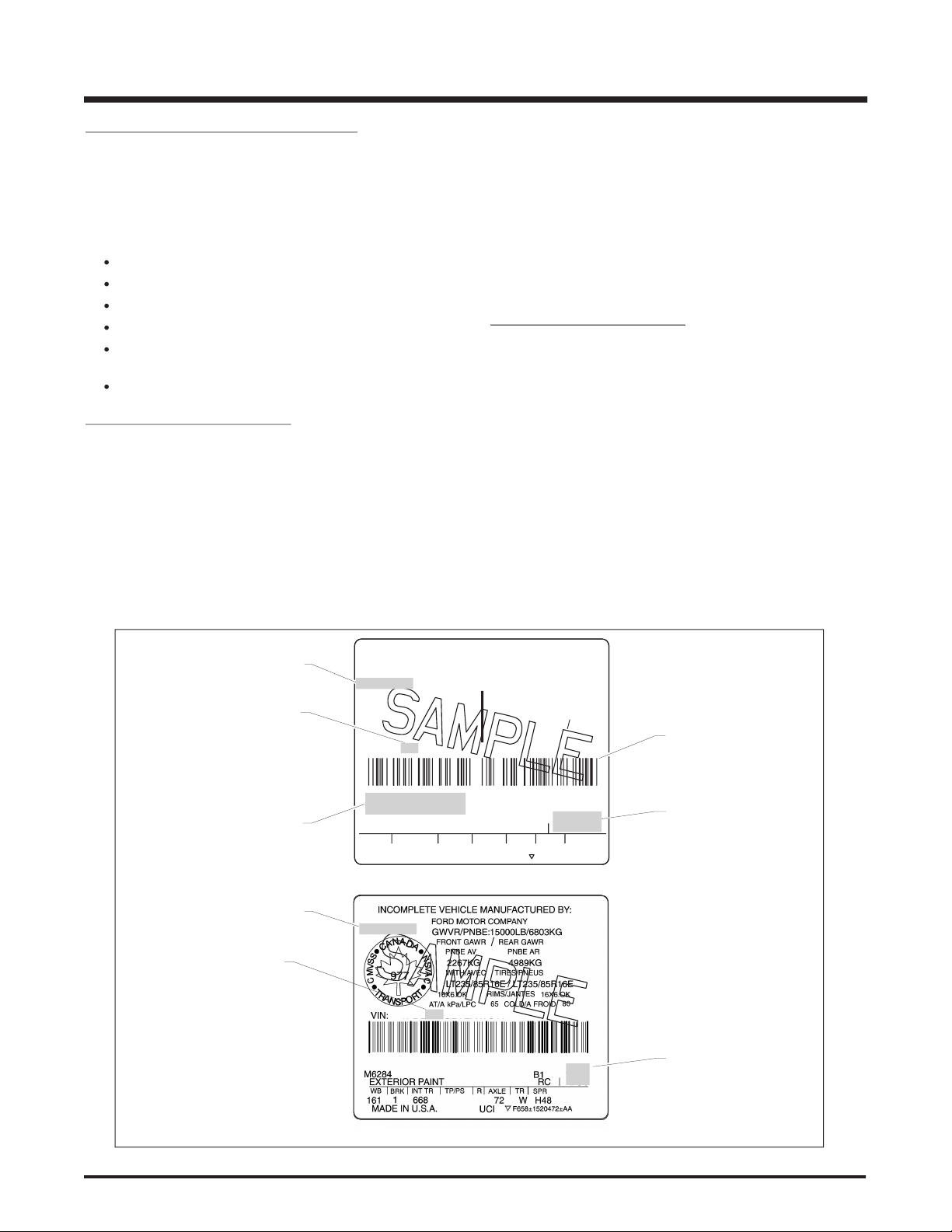
VEHICLE DESCRIPTION
The cover of this manual identifies the three incomplete
vehicle con gurations for which compliance representations
for the speci c vehicle to which this manual belongs. The label
vehicle with the corresponding VIN.
The GVWR
The front and rear GAWRs
Tire and wheel size
vehicle may be manufactured
All E-Series incomplete vehicles manufactured by Ford Motor
The 5th, 6th, and 7th digits of the Vehicle Identification
three digits are used in the Completed Vehicle Types charts
the VIN on the incomplete vehicle label, when provided, will
The Canadian Motor Vehicle Safety Act and Regulations
with the National Safety mark on it on vehicles manufactured
for sale in Canada. A label representative of those installed by
vehicle type charts on page 8 will identify incomplete vehicles
wish to rely on the Statements of Conformity or, in some cases,
vehicle and the label on the front of this manual will identify
the prep package.
INCOMPLETE VEHICLE MANUFACTURED BY
FORD MOTOR COMPANY
MADE IN U.S.A.
GVWR:
:
FRONT GAWR
:
VIN
:
PSI COLD
PSI COLD
WITH
TIRES
RIMS
WITH
TIRES
RIMS
REAR GAWR
:
EXTERIOR PAINT COLORS
WB
TYPEGVW
BODY
TRANS
AXLE
TAPE
SPRINGS
161
F379
AJ8
E 6
5
N Y
4200LB
1905KG
LT215/85R16D
16X6K
11000LB/4989KG
8250LB
3742KG
LT215/85R16D
16X6K
65
DUAL
58
F85B1520472AB
TYPICAL E-SERIES - U.S.
AT
AT
TYPICAL E-SERIES - CANADA
VSO
410047
BAR CODE V.I.N
(CALIFORNIA
)
VSO
VEHICLE
DATE OF
MANUFACTURE
VEHICLE TYPE
(SEE CHART
ON PAGE 8)
OPTIONAL
PREP PACKAGE
VSO
VEHICLE
DATE OF
MANUFACTURE
VEHICLE TYPE
(SEE CHART
ON PAGE 8)
01/05
DATE
01/05
DATE
1FDKE37HZ5HA24638
EQUIPPED WITH THE FORD
AMBULANCE PREP PKG.
VSO
1019
.
1FDKE37HZ5HA24639
Page 10
E-SERIES (May, 2004) 9
COMPLETED VEHICLE TYPES
COMPLETED VEHICLES
5TH, 6TH, 7TH
VIN DIGIT
E-Series
E11 Incomplete E-150 Wagon X 6
E14 Incomplete E-150 Regular Van X 5
E24 Incomplete E-250 Regular Van X 5
E31 Incomplete E-350 Super Duty Wagon X 6 6
E34 Incomplete E-350 Super Duty Regular Van X 5 1
E35 E-350 Super Duty Cutaway X 3 1 4 2
E39 E-350 Super Duty Basic (Stripped) Chassis X
E45 E-450 Super Duty Cutaway X 3 1 4 2
E49 E-450 Super Duty Basic (Stripped) Chassis X
S24 Incomplete E-250 Extended Van X 5
S31 Incomplete E-350 Super Duty Extended Wagon X 6 6
S34 Incomplete E-350 Super Duty Extended Van X 5 1 5
IMPORTANT:
Ford Motor Company makes no representation that the
completed vehicle types listed above are the only vehicle
types appropriate for the incomplete vehicles listed.
However, if a unit is completed as a vehicle type other
than as listed above, the Statements of Conformity may
not be applicable.
INCOMPLETE VEHICLES
(1) Ambulance Prep Package
(2) School Bus Prep Package
- E-350 available on 9600 lb GVWR Single Rear Wheels (SRW),
and 11,500 lb GVWR Dual Rear Wheels (DRW) only
(3) Motorhome Prep Package
(4) Shuttle Bus Prep Package
(5) Recreational Van
(6) Center Aisle Seat Prep Package
TRUCK
TRUCK
(WALK-IN VAN)
MPV
MPV
(AMBULANCE)
BUS (NOT
SCHOOL BUS)
SCHOOL BUS
COMPLETED VEHICLE TYPES
E-SERIES (May, 2004)8
Page 11

STATEMENTS OF CONFORMITY
The following Statements of Conformity apply to vehicles that are produced for sale or importation into the United States
or Canada. The term “Incomplete Vehicle Types” in these statements refers to the three types of the vehicles illustrated on
this manual’s cover and listed in the chart on page 8.
The number preceding each Statement of Conformity refers to the number designation for a Part or a Section of Part 571
of the Federal Motor Vehicle Safety Standard.
The statements provided for each safety standard number are appropriate compliance representations for each Canadian safety
standard number if this incomplete vehicle, identied by the VIN on the front of the document, was manufactured by Ford Motor
Company for sale or use in Canada, except as may be noted at the conclusion of each safety standard number.
PART
565.4 The statement below is applicable to all incomplete
vehicle types except the Basic (Stripped) Chassis:
This vehicle, when completed, will conform to Part 565.4,
Vehicle Identication Number, if the vehicle identication
number mounted on the top of the instrument panel is
not removed, altered, or modied and no actions are
taken by the subsequent stage manufacturer that would
obstruct the readability of the Vehicle Identification
Number mounted on the top of the instrument panel.
565.4 The statements below are applicable to the following
incomplete vehicle type:
• E-Series Basic (Stripped) Chassis
This vehicle, when completed, will conform to Part
565.4, Vehicle Identication Number, if:
• The E-Series vehicle identication number printed on
the label afxed to the cover of this manual is mounted
and displayed in accordance with the requirements
of this Standard.
101 The statements below are applicable to the following
incomplete vehicle types when equipped with a
driver seat:
• Incomplete E-Series Van or Wagon
• Cutaway
This vehicle, when completed, will conform to Standard
101, Controls and Displays if:
• The controls, displays, and their identifications
supplied by Ford Motor Company are not removed,
relocated, altered, or modied.
• The components, wiring, and power supply installed
by Ford Motor Company to illuminate any control,
display, or their identification are not removed or
altered so as to affect lighting performance.
• Components added to the vehicle do not obstruct
the driver’s ability to operate or visually locate the
controls, displays, and their identications.
• The driver-seat is not replaced, relocated, or modied
other than for the addition of seat trim.
Any controls, displays, and illumination added to this
vehicle must conform to the requirements of this
Standard.
101 The statements below are applicable to the following
incomplete vehicle types with no driver-seat:
• Incomplete E-Series Van
• Cutaway
This vehicle, when completed will conform to Standard
101, Controls and Displays if:
• The Seating Reference Point (see denition on page
5) and the seat back torso angle of the driver-seat
when completed or installed by a subsequent stage
manufacturer are located as shown in the Figure C
page 32, for E-Series type vehicles.
• The c on tr ol s, displays, and their identifications
supplied by Ford Motor Company are not removed,
altered, or relocated.
• The components, wiring, or power supply installed by
Ford Motor Company to illuminate any control, display,
or their identication are not removed or altered so
as to affect lighting performance.
• Components added to the vehicle do not obstruct
the driver’s ability to operate or visually locate the
controls, displays, and their identications.
Any controls, d is pl ays, an d illumination added to
this vehicle must conform to the requirements of this
Standard.
101 The statement below is applicable to the following
incomplete vehicle type:
• E-Series Basic (Stripped) Chassis
Conformity with Standard 101, Controls and Displays, is
not substantially affected by the design of this incomplete
vehicle; accordingly, Ford Motor Company makes no
representation as to conformity with this Standard.
E-SERIES (May, 2004) 9
STATEMENTS OF CONFORMITY
Page 12
E-SERIES (May, 2004) 11
102 The statements below are applicable to all incomplete
0
0
0
0
0
0
18
H
0
0
0
0
50
60
70
80
90
100
10
20
30
40
0
M
PH
U
N
LE
A
D
E
D
F
U
E
L
O
NL
Y
BRAKE
SERVIC
E
E
NG
I
N
E
S
O
O
N
F
H
C
E
P
R
N
1
INSTRUMENT
CLUSTER
CABLE
STEERING
COLUMN
CABLE
THUMB WHEEL
COLUMN SHIF
T
LEVER
FRONT OF
VEHICLE
CABLE RETENTION
BRACKET
SHIFT LEVER
RETAINER PI
N
N800705 SCRE
W
TORQUE 20-29 IN.LB
.
[ ] ALL DIMENSIONS ARE INCHES
3.0-3.5 LB. WEIGHT
HAND TOOL
[2.375] ± 0.25 DIA.
(PRNDL)
HOLE: [1.125] DIA.
X [2.188] 0.25 DEEP
(PRNDL) ADJUSTMENT TOLERANCE
+
+
RIGHT LIMITLEFT LIMIT TARGET
D
±
vehicle types except the Basic (Stripped) Chassis:
This vehicle, when completed, will conform to Standard
102, Transmission Shift Leve r Sequence, Starter
Inte rlock, and Transm ission Braki ng Effect, if no
alterations or adjustments are made to the transmission,
shift cable, transmission outer shift lever, shift cable
bracket, vacuum tubes, vacuum pump system, brakeshift interlock system, starter interlock system, wiring
circuit from the interlock switch to the power source, and
transmission gear selector indicator (PRNDL).
If an auxiliary transmission is added to this vehicle, it
must conform to the requirements of this Standard.
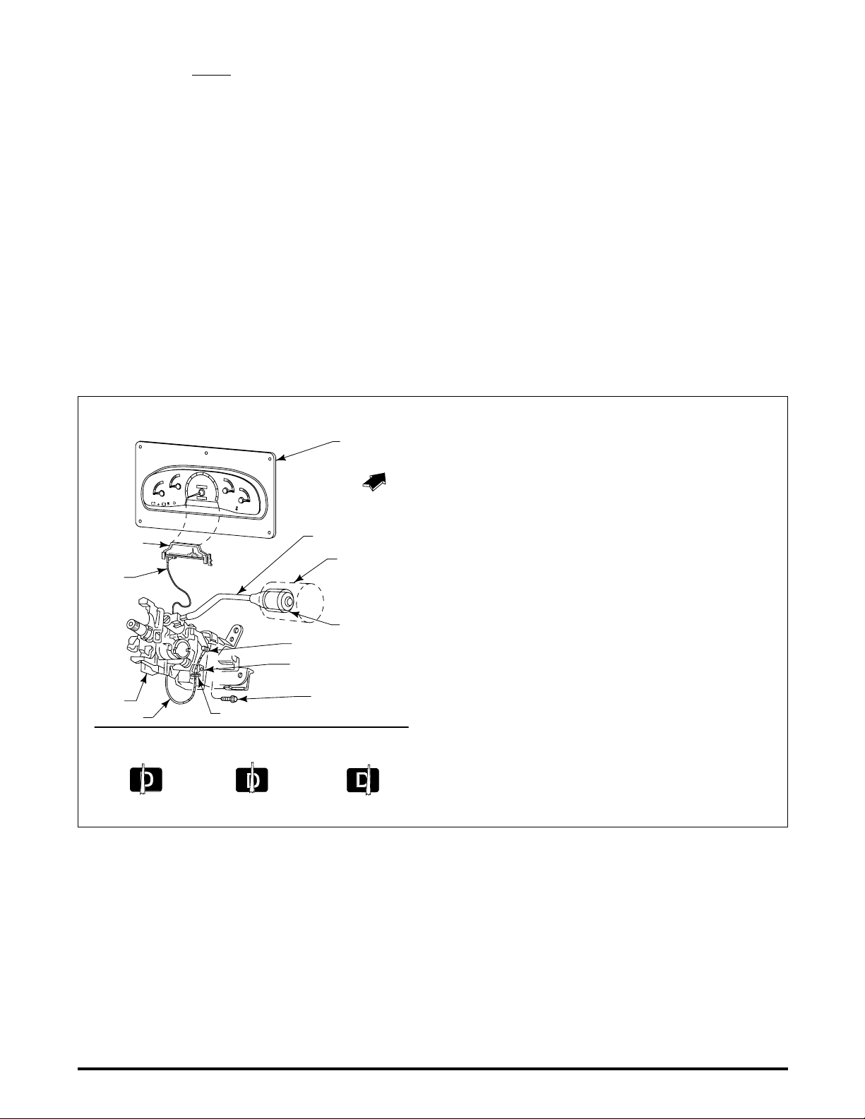
INSTALLATION OF GEAR SELECTOR INDICATOR (PRNDL) FOR E-SERIES BASIC (STRIPPED) CHASSIS
102 The statements below are applicable to the following
incomplete vehicle type:
• E-Series Basic (Stripped) Chassis
This vehicle, when completed, will conform to Standard
102, Transmission Shift Leve r Sequence, Starter
Interlock, and Transmission Braking Effect if:
• No alterations or ad ju stments are made to the
transmission, shift cable, transmission outer shift
lever, shift cable bracket, vacuum tubes, vacuum
pump system, brake-shift interlock system, the starter
interlock system, and wiring circuit from the interlock
switch to the power source.
• The E-Series Basic (Stripped) Chassis is equipped
with a temporary transmission gear selector indicator
(PRNDL) which must be replaced with the cluster and
transmission gear selector indicator (PRNDL) that is
shipped with the vehicle in the dunnage box and must
be installed and adjusted following the instructions
and specications shown in the gure below.
If an auxiliary transmission is added to this vehicle, it
must conform to the requirements of this Standard.
1. Route the cable after the instrument cluster is installed in
the vehicle. Do not kink the cable. Do not bend the cable
to a radius less than 4.5 inches. Route the cable from
the cluster in a counter-clockwise direction, under the
steering column, using the screw provided. Do not wrap
the cable around the steering column. The steering column
shroud installation should not affect the cable routing
or function.
2. Pull on the cable end loop for a functional check. The
cable should operate with a similar effort as required prior
to routing. Then place the cable loop on the shift lever
retainer pin.
3. Rotate the column shift lever clockwise until it bottoms
out in rst gear.
4. Rotate the column shift lever counter-clockwise 3 detents for
Overdrive “Oval D” position for TorqShift™ transmissions.
5. Install a 3 pound weight, as dened in this illustration, on
the end of the column shift lever.
6. Center the pointer in the middle of the “Oval D” position by
rotating the thumb wheel.
7. Remove the 3 pound weight. The pointer must be within
the tolerances as dened in this illustration.
8. After the steering column shrouds are installed, the
transmission gear selector indicator (PRNDL) system must
be checked for proper operation.
STATEMENTS OF CONFORMITY
E-SERIES (May, 2004)10
Page 13
103 The statement below is applicable to all incomplete
vehicle types except the Basic (Stripped) Chassis:
This vehicle, when completed, will conform to Standard
103, Windshield Defrosting and Defogging Systems, if
no alterations or adjustments are made to heater and
blower assemblies, ducting, operating controls, electrical
circuit from the blower assembly to the power source,
windshield, coolant hoses from the radiator or engine to
the heater, and if no obstructions are added that restrict
or otherwise redirect the air flow from the defroster
outlets to the windshield.
103 The statement below is applicable to the following
incomplete vehicle type:
• E-Series Basic (Stripped) Chassis
Conformity with Standard 103, Windshield Defrosting
and Defogging Systems, is not substantially affected
by the design of this incomplete vehicle; accordingly,
Ford Motor Company makes no representation as to
conformity with this Standard.
104 The statement below is applicable to all incomplete
vehicle types except the Basic (Stripped) Chassis:
This vehicle when completed, will conform to Standard
104, Windshield Wiping and Washing Systems, if no
alterations are made to the windshield, the windshield
wiping and washing system, including the electrical
circuit from the windshield wiping and washing motors
to the power source, and if no obstructions are added
that restrict or otherwise redirect uid ow from the
washer nozzles to the windshield.
104 The statement below is applicable to the following
incomplete vehicle type:
• E-Series Basic (Stripped) Chassis
Conformity with Standard 104. Windshield Wiping
and Washing Systems, is not substantially affected
by the design of this incomplete vehicle; accordingly,
Ford Motor Company makes no representation as to
conformity with this Standard.
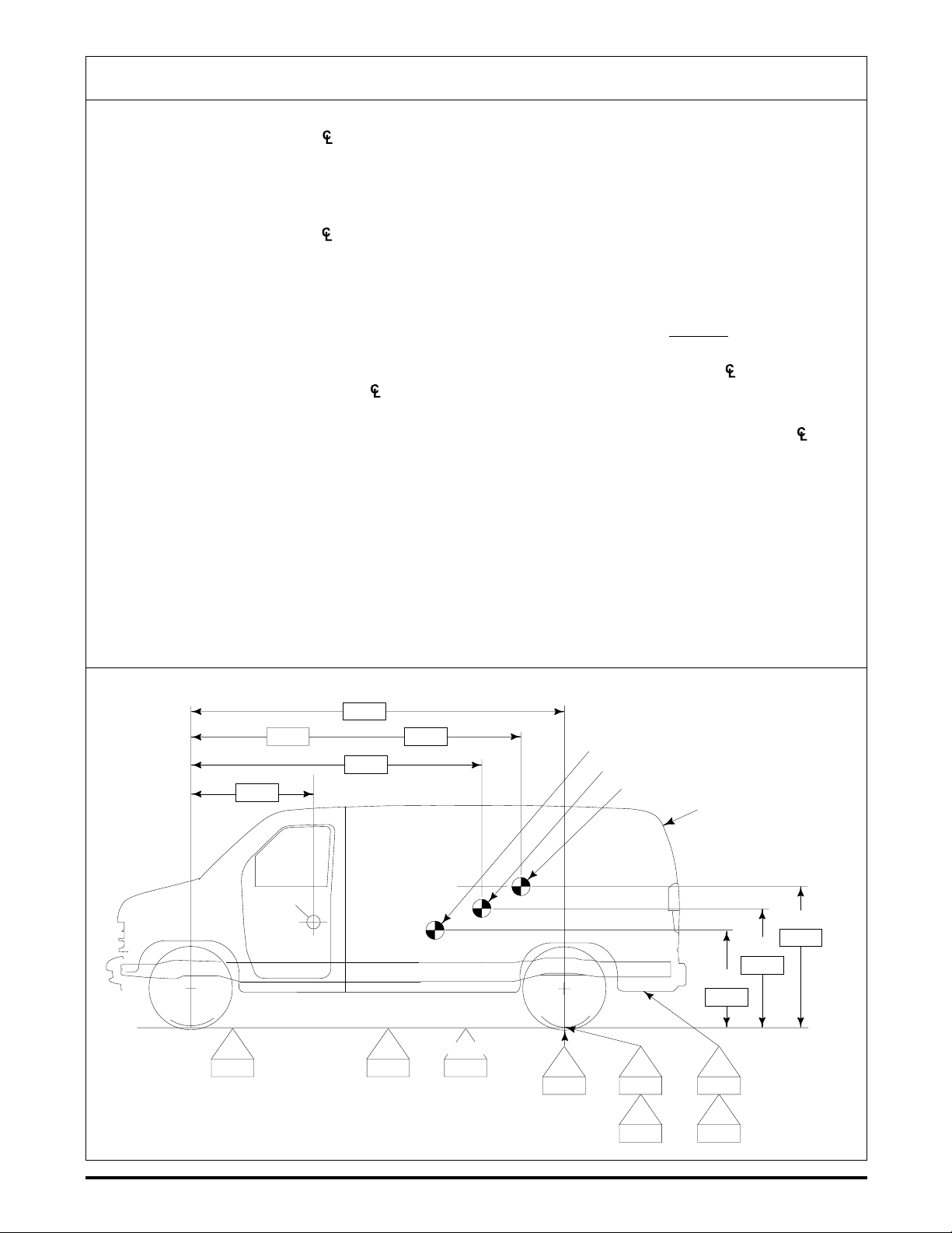
105 INFORMATION
Incomplete vehicle weight and dimensional information
required for center of gravity calculations are available
in the Ford Source Book. See your local Ford Dealer
and refer to appropriate model year and specic vehicle
for required information.
Abbreviation denitions and a vehicle diagram to assist
with the equations for the Standard 105 segment are
shown on page 14.
NOTE: 105 is an example of a standard with conformity
statements that contain minimum requirements for
completed vehicle Unloaded Vehicle Weight (UVW, see
definition on page 5). Maximum UVW requirements
are also found in various sections of this manual (see
especially Standards 212/219 and 301 and related table,
Table A). Completed vehicles must meet UVW limits
imposed by all applicable requirements.
105 The statements below are applicable to the E-Series
cutaway when equipped with the School Bus Prep
package and completed as a school bus:
This vehicle when completed, will conform to Standard
105, Hydraulic and Electric Brake Systems, if:
• No alterations, modications, or replacements are
made to the following:
– Service or parking brake system
– Antilock brake system
– Vacuum system
– Wheels and tires
– Brake system indicator lamp and wiring
– Brake system reservoir labeling
– Suspension ride height or spring rate
– Hydro-Boost system
– Power Steering pump and lines if used with
Hydro-boost
– Engine belt drive system
– Wheelbase
• The E-350 SRW Unloaded Vehicle Weight (see
denition on page 5) is not less than the minimum
value of 2540 kg [5600 lb].
• The E-350/450 DRW minimum UVW must be at least
the weights shown on the following table:
MINIMUM UNLOADED VEHICLE WEIGHT (UVW)
Vehicle Weight Kilogram [Pound]
E-350 DRW 3673 [8100]
E-450 DRW 4128 [9100]
• The maximum GAWRs and GVWR, as identied on
the cover of this document, are not exceeded.
• The transverse center of gravity is less than 50.8 mm
[2.0 in] either side of the vehicle centerline for E-350
only.
• Service or parking brake pedal assembly operation
must not be restricted by any alteration or added
components.
• The horizontal and vertical center of gravity, of the
completed vehicle at Unloaded Vehicle Weight, is
within the minimum and maximum locations as dened
in the following table:
CENTER OF GRAVITY FOR E-SERIES CUTAWAY
COMPLETED AS A SCHOOL BUS
E-350 E-350 E-450
Location SRW DRW DRW
mm [in] mm [in] mm [in]
Vertical Maximum (1) 302.0
[11.9]
Horizontal Maximum (2) 2159.0 2718.0
[85.0] [107.0]
Horizontal Minimum (2) 1651.0
[65.0]
E-SERIES (May, 2004) 11
(1) Measured from top of frame at a point midway between
the centerlines of the front and rear axles.
(2) Measured rearward from the centerline of the front axle.
STATEMENTS OF CONFORMITY
Page 14
E-SERIES (May, 2004) 13
105 The statements below are applicable to the following
incomplete vehicle types if the GVWR is between
3500 kg [7716 lb] and 3629 kg [8000 lb]:
• Incomplete E-Series Van or Wagon
This vehicle, when completed, will conform to Standard
105, Hydraulic and Electric Brake Systems, if:
• No alterations, modications, or replacements are
made to the following:
– Service or parking brake system
– Antilock brake system
– Vacuum system
– Wheels and tires
– Brake system indicator lamp and wiring
– Brake system reservoir labeling
– Suspension ride height or spring rate
– Wheelbase
• Any removal of a Ford body or chassis component is
accompanied by the addition of equal weight.
• The maximum GAWRs and GVWR, as identied on
the cover of this document, are not exceeded with
the vehicle weight at Unloaded Vehicle Weight + 400
lb passenger load.
• The ser v ice or pa rking bra ke pedal assembly
operation is not restricted by any alteration or added
components.
• The horizontal center of gravity of the Second Unit
Body (SUB) is rearward of L
vehicle description in the chart below. Lmin does not
apply to a SUB of 120 lb or less when installed rearward
of the front seats and forward of the centerline of the
rear axle. (Do not restrict the E-Series seat travel and
provide seatback clearance to obtain the torso angle
as shown in Figure C page 32).
• The horizontal center of gravity for the SUB is:
† for the appropriate
min
– At or forward of the r ear axle center line. The
vertical center of gravity for the completed vehicle
at Unloaded Vehicle Weight + 400 lb passenger load
CGv (Equation A) must not exceed 36.0 inches,
when measured from the ground.
– Behind the rear axle centerline. The vertical center
of gravity for the completed vehicle at Unloaded
Vehicle Weight + 400 lb passenger load must
fall within the appropriate range determined from
Table E, page 16. The value of CGh (Equation B),
which approximates the horizontal center of gravity
of the completed vehicle, is used in Table E, to
determine the vertical center of gravity limits for the
completed vehicle. The value CGv (Equation A),
which approximates the vertical center of gravity
of the completed vehicle, must fall within the
appropriate range determined from Table E.
EQUATION A
CGvbWb + CGvc Wc + 25P
CGv =
EQUATION B
Wrb + Wrc +
CG
105 (Continued Next Page)
(
=
h
W
t
P x CG
(
W
t
WB
hp
)
)
x WB
HORIZONTAL CENTER OF GRAVITY
FORWARD LIMIT
Wheelbase L
Vehicle Millimeter [inch] Millimeter [inch]
E-250 3505 [138] 1524 [60]
min
† L
= the minimum horizontal center of gravity of the
min
SUB measured in inches rearward from the centerline
of the front axle.
STATEMENTS OF CONFORMITY
E-SERIES (May, 2004)12
Page 15
105 (Continued)
105 The statements below are applicable to the following
incomplete vehicle types except when completed as a
school bus, and if the GVWR is between 3629 kg [8000
lb] and 6373 kg [14,050 lb] inclusive:
• Incomplete E-Series Van or Wagon
• E-Series Cutaway
• E-Series Basic (Stripped) Chassis
This vehicle, when completed, will conform to Standard
105, Hydraulic and Electric Brake Systems, if:
• No alterations, modications, or replacements are
made to the following:
– Service or parking brake system
– Antilock brake system
– Vacuum system
– Wheels and tires
– Brake system indicator lamp and wiring
– Brake system reservoir labeling
– Suspension ride height or spring rate
– Hydro-boost system
– Power steering pump and lines if used with Hydro-
boost
– Engine belt drive system
– Wheelbase
• No additional sound deadene r or r ust proofing
material, that may be applied to the vehicle, can
interfere with proper parking brake cable function.
• No par t of add on equipment, i.e. toolboxes, flat
bed attaching brackets, etc., can interfere with the
movement of parking brake cables or air ow to rear
brake assembly.
• Any removal of a Ford body or chassis component is
accompanied by the addition of equal weight.
• E-Series Cutaway and Basic (Stripped) Chassis
vehicles conform to the minimum SUB weights found
in Table B, page 15.
• The maximum GAWRs and GVWR, as identied on
the cover of this document, are not exceeded with
the vehicle weight at Unloaded Vehicle Weight +
Passenger Load (P). (See E-Series Passenger Load
chart on this page.)
• The ser v ice or pa rking bra ke pedal assembly
operation is not restricted by any alteration or added
components.
• The SUB horizontal center of gravity must be at or
forward of the rear axle centerline for the following
vehicles:
- E-350/450 Basic (Stripped) Chassis
- E-350 Super Duty Cutaway (DRW)
- E-450 Super Duty Cutaway
The horizontal center of gravity for the SUB is:
– At or forward of the rear axle centerline. The vertical
center of gravity for the completed vehicle at GVWR
CGv (Equation C) must not exceed 48.0 inches
when measured from the ground.
– Behind the rear axle centerline. The vertical center
of gravity for the completed vehicle at GVWR must
fall within the appropriate range determined from
Table E page 16. The value of CGh (Equation D),
which approximates the horizontal center of gravity
of the completed vehicle, is used in Table E to
determine the vertical center of gravity limits for
the completed vehicle. The value of CGv (Equation
C) which approximates the vertical center of
gravity of the completed vehicle must fall within the
appropriate range determined from Table E.
EQUATION C
CGvbWb + CG
CGv =
Wc + W
(
vc
GVWR
l
)
+ 25P
EQUATION D
CGh =
Wrb + Wrc +
(
P x CG
(
WB
hp
)
+ W
)
rl
x WB
GVWR
E-SERIES PASSENGER LOAD
GVWR [lb] P [lb]
0 - 7716 397
7717 - 10,000 400
10,001 - 19,000 500
E-SERIES (May, 2004) 13
STATEMENTS OF CONFORMITY
Page 16
E-SERIES (May, 2004) 15
FMVSS 105 & 135 DEFINITIONS AND CALCULATION ILLUSTRATION FOR INCOMPLETE E-SERIES VEHICLES
W
c
W
rl
W
rb
W
b
W
rc
W
l
P
CG OF SUB
CG OF COMPLETED VEHICLE
CG OF CHASSIS
CG
h
CG
hp
CG
vc
WB
CG
v
CG
vb
W
t
GVWR
CG
hl
L
SUB
L† = Horizontal distance in inches between the SUB
center of gravity and the of the front axle.
P = Passenger load (See E-Series Passenger Load
Table page 13).
CGv = Vertical distance from the ground to the center of
gravity [inches] of the completed vehicle.
CGh = Horizontal distance from of the front wheels to
completed vehicle center of gravity [inches].
CGvb = Vertical distance from the ground to the center of
gravity of the SUB and/or permanently attached
added equipment [inches].
CGvc = Vertical distance from the ground to the center
of gravity of the chassis [inches] (including
cab if original equipment). (Taken from Table
F, page 16).
CGhp = Horizontal distance from the of the front
wheels to the P [inches] (passenger load) (taken
from Table D, page 16).
Wb = Weight of the SUB and/or permanently attached
added equipment [pounds].
Wrb = Weight at t he rear whe els o f the S UB
and/or permanently attached added equipment
[pounds].
Wrc = Weight at the rear wheels of the vehicle (chassis
and cab) (fuel tanks full) [pounds]. Including
option weight.
† Required for <8000 lb. GVWR calculations only. ‡ Required for ≥8000 lb. GVWR calculations only.
Wc = Weight of the vehicle (chassis and cab) (fuel
tanks full) [pounds]. Including option weight.
WB = Vehicle wheelbase [inches].
Wt = Total unladen weight = (Wb + Wc + P)
GVWR = Gross Vehicle Weight Rating of the vehicle
[pounds].
WI‡ = Remaining cargo capacity [pounds].
Where: Wl = GVWR - (Wb + Wc + P)
Wrl‡ = Weight of the remaining cargo capacity on the
rear wheels [pounds].
CGhI‡ = Horizontal distance from the
WrI =
(CGhI)W
WB
I
of the front wheels
to the cargo center of gravity [inches] (taken from
Table C page 16). For many common vehicles,
the CGhI is not given in the table, then it may
be estimated as the distance from the of the
front wheel to the horizontal midpoint of the cargo
area.
SUB = A Second Unit Bo dy consis ts of the bod y
structure and/or all the cargo carrying, work
performing, and/or load bearing components
and/or equipment installed by a subsequent
stage manufacturer on an incomplete vehicle,
such that the incomplete vehicle becomes a
completed vehicle.
STATEMENTS OF CONFORMITY
E-SERIES (May, 2004)14
Page 17
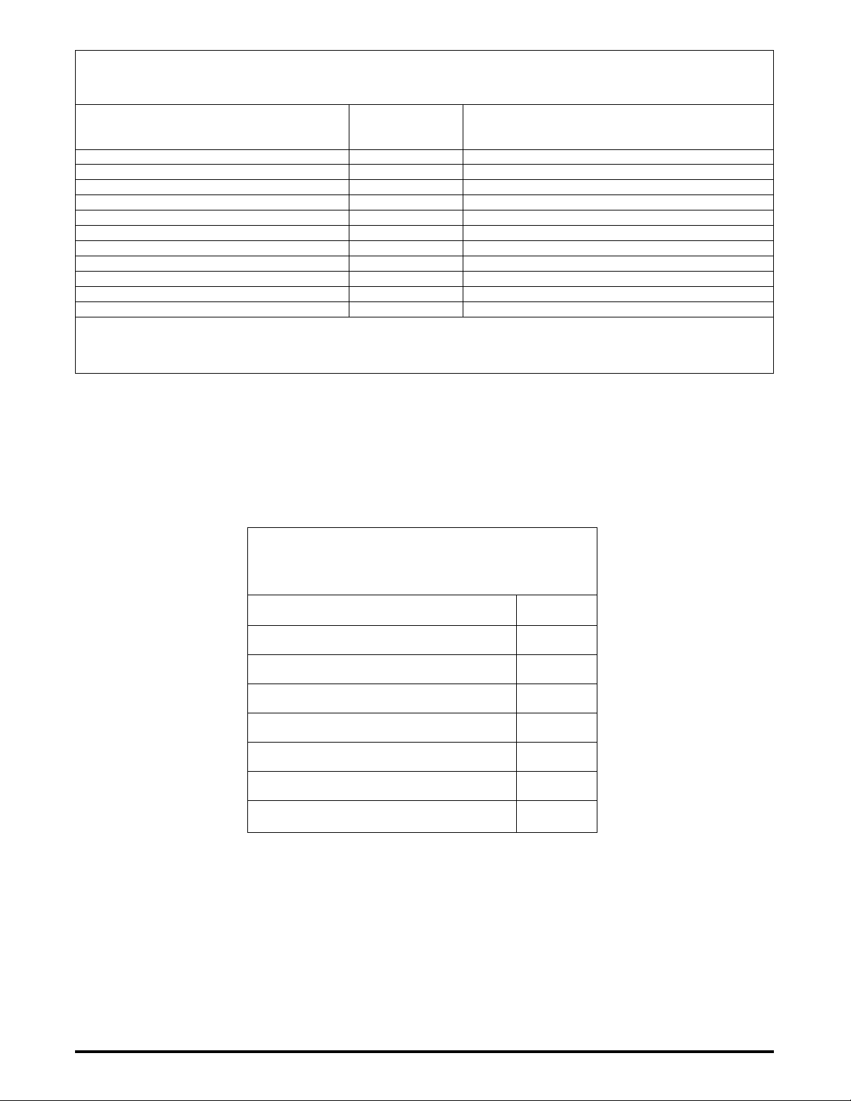
TABLE A
Maximum Unloaded Vehicle Weight (UVW) for Incomplete Vehicles When Completed (2)
(This Information Does Not Apply To Vehicles Over 4536 kg [10,000 lb] GVWR)
Wheelbase
Millimeter Maximum
Model [inch] Unloaded Vehicle Weights – Kilogram [pound]
E-150 Regular Van 3505 [138] 2699 [5950](1)
E-150 Regular Wagon 3505 [138] 2699 [5950](1)
E-250 Regular and Extended Van 3505 [138] 3130 [6900]
E-350 Regular and Extended Van 3505 [138] 3583 [7900]
E-350 Regular and Extended Wagon 3505 [138] 3583 [7900]
E-350 Cutaway 3505 [138] 3856 [8500]
E-350 Basic (Stripped) Chassis SRW 3505 [138] 3946 [8700]
E-350 Basic (Stripped) Chassis DRW 3505 [138] 3946 [8700]
E-350 Basic (Stripped) Chassis SRW 4013 [158] 3946 [8700]
E-350 Basic (Stripped) Chassis DRW 4013 [158] 3946 [8700]
E-350 Basic (Stripped) Chassis DRW 4470 [176] 3946 [8700]
(1) 2767 kg [6100 lb] When completed with 6 or less designated seating positions.
(2) Maximum unloaded vehicle weight values shown in this table are limits for purposes of F/CMVSS conformity only. See Emission
Certication information on page 49 for possible additional weight restrictions to meet emission requirements.
TABLE B
MINIMUM SUB WEIGHT
Minimum unloaded vehicle weight for cutaways completed as
school buses is dened in Standard 105 requirements on page 11.
Kilogram
Model [Pound]
E-350 Cutaway DRW 204
3505mm [138 in] WB [450]
E-350 Cutaway DRW 238
4013mm [158 in] WB [525]
E-350 Cutaway DRW 238
4470mm [176 in] WB [525]
E-450 Cutaway DRW 238
4013mm [158 in] WB [525]
E-450 Cutaway DRW 238
4470mm [176 in] WB [525]
E-350 Basic (Stripped) Chassis DRW 862
All WB [1900]
E-450 Basic (Stripped) Chassis DRW 998
All WB [2200]
E-SERIES (May, 2004) 15
STATEMENTS OF CONFORMITY
Page 18

E-SERIES (May, 2004) 17
TABLE C
CGhl = Horizontal distance from front axle to cargo CG:
Model WB (in) CGhl (in)†
Regular Van 138 116
†Extended Van or Extended Wagon 138 126
†Cutaway (SRW) 138 121
(DRW) 138 127
†Comm. Cab/Box Partition (DRW) 158 134
†RV (DRW) 158 138
†Comm. No Partition (DRW) 158 143
†RV (DRW) 176 153
†Comm. (DRW) 176 160
† If CGhI is not given in the table or if the location of your cargo is
not in the normal cargo area, then your CGhI may be estimated
as the distance from the of the front wheel to the horizontal
midpoint of the cargo area.
TABLE D
CGhp = Horizontal distance from front wheel to front
passenger load. (Dimensions are inches)
All E-Series† 48.5
† Except the E-Series Basic (Stripped) Chassis where the distance
from the of the front axle to the H point of the driver must be
measured.
TABLE F
CGVC = Vertical distance from ground to chassis CG
(Dimensions are inches)
E-150 & E-250 Van <8000 lb GVWR = 28.5
E-250/350 SRW Van or Wagon >8000 lb GVWR = 32.0
E-350 Cutaway = 28.0
E-450 Cutaway = 26.5
E-350/450 Basic (Stripped) Chassis = 26.5
TABLE E
CGv = Vertical distance from the ground to the completed vehicle center of gravity [inch].
GVWR <8000 lb Use Equations A & B, page 12
Place the CGh of the vehicle (from Equation B) into the appropriate equations below to determine the allowable range
of the CGv. If the actual CGv (from Equation A) is within the range calculated, the center of gravity location is acceptable.
Equation for CGv Range
Model WB Upper Limit Lower Limit
E-150 138 CGv = 1.39 x CGh - 46.9 1.39 x CGh - 58.7
E-250 138 CGv = 1.39 x CGh - 47.1 1.39 x CGh - 59.0
GVWR > 8000 lb to <19000 lb Use Equations C & D, page 13
Place the CGh of the vehicle (from Equation D) into the appropriate equations below to determine the allowable range
of the CGv. If the actual CGv (from Equation C) is within the range calculated, the center of gravity location is acceptable.
Equation for CGv Range
Model WB Upper Limit Lower Limit
E-250 138 CGv = 1.27 x CGh - 59.0 1.27 x CGh - 77.5
E-350 (SRW) 138 CGv = 1.27 x CGh - 60.0 1.27 x CGh - 80.0
<9600 Ib GVWR 158 CGv = 1.27 x CGh - 69.5 1.27 x CGh - 90.7
STATEMENTS OF CONFORMITY
E-SERIES (May, 2004)16
Page 19

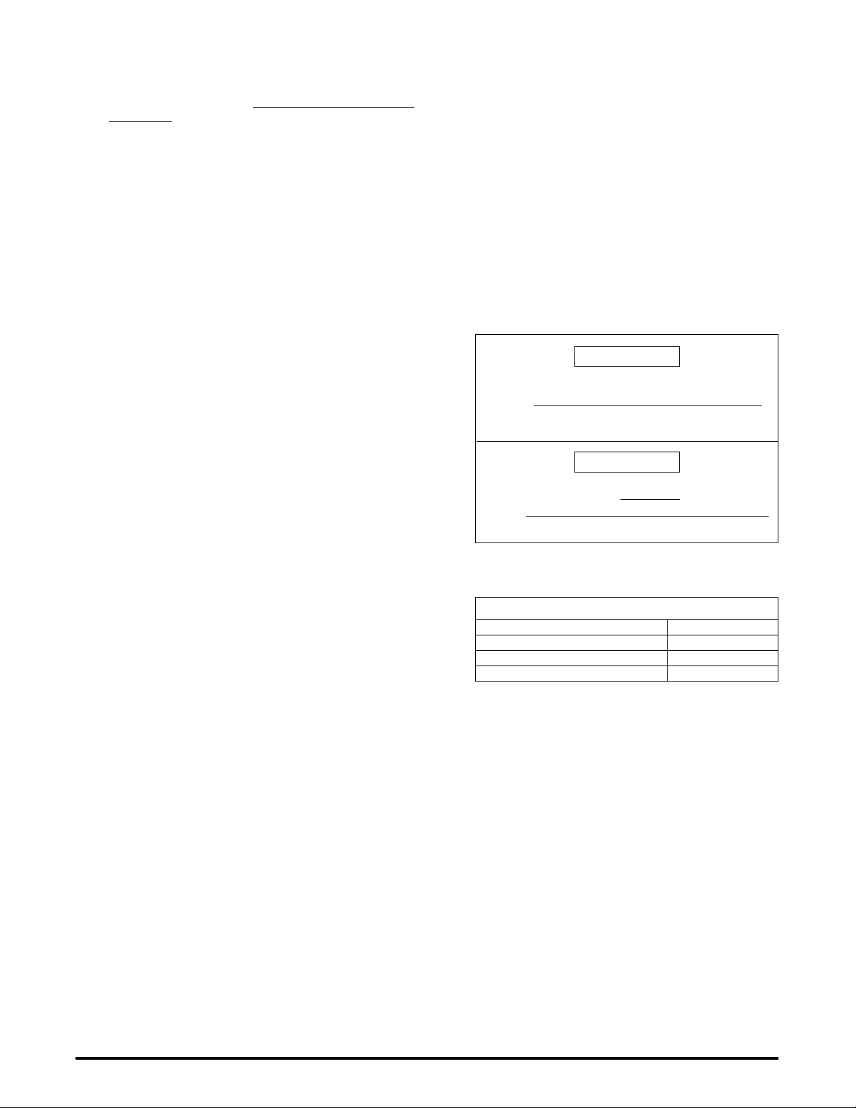
106 The statement below is applicable to all incomplete
TO INSTALL “CHMSL”
UNWRAP TAPE FROM
HARNESS IN THIS AREA
AND REMOVE JUMPER
CONNECTION TO EXPOSE
THE “CHMSL CONNECTOR”.
E-SERIES CUTAWAY
FRONT OF
VEHICLE
THE “CHMSL” ELECTRICAL CONNECTION FOR
AN ECONOLINE BASIC (STRIPPED) CHASSIS IS
PROVIDED IN A DETAILED SCHEMATIC WHICH
IS PACKAGED WITH THE BODY BUILDER
ELECTRICAL CONNECTORS.
vehicle types:
This vehicle, when completed, will conform to Standard
106, Brake Hoses, if the brake hose assemblies supplied
by Ford Motor Company are not removed, relocated,
altered, or modied and if no brake hose assemblies
are added.
108 In addition to the statements pertaining to particular
incomplete vehicle types which follow on pages
18 and 19, the statements immediately below,
concerning Standard 108 Lamps, Reective Devices,
and Associated Equipment are applicable to all
incomplete vehicle types except the Basic (Stripped)
Chassis:
No additio nal c omponent s may be added to the
vehicle which require the use of tools to remove such
components, for access to the headlamp aiming devices
as provided by Ford Motor Company.
Daytime Running Lamps (DRL’s); Light Trucks for sale
or use in Canada are equipped with DRL’s that meet
the Canadian DRL requirements. As manufactured for
Canada, the E-Series vehicles will meet the FMVSS 108
requirement for DRL’s when DRL’s are provided.
Co nformi ty with St and ard 10 8, S.1 2, Headlam p
Concealment Devices, are not substantially affected
by the design of this incomplete vehicle; accordingly,
Ford Motor Company makes no representation as to
conformity with this Standard.
108 The statement below is applicable to the following
vehicle type with a GVWR of 4536 kg [10,000 lb] or
less and a vehicle width less than 2032 mm [80.00
in]:
• Cutaway
This vehicle, when completed, will conform to Standard
108, L amps, Reflective Devices, and A ssociated
Equipm ent if a Cent er High Mount ed S top Lamp
(CHMSL) is installed so it meets all the requirements of
this standard and is connected to the electrical power
source as provided by Ford Motor Company. See the
gure below for circuit location.
E-SERIES (May, 2004) 17
CENTER HIGH-MOUNTED STOP LAMP (CHMSL)
ELECTRICAL CONNECTOR LOCATION
STATEMENTS OF CONFORMITY
Page 20

E-SERIES (May, 2004) 19
TABLE G
Standard 108 Lighting Equipment
E-Series
Completed
as Truck,
MPV, Bus or
School Bus
Width less than
2032 mm [80 in]
Item
Width 2032 mm
Headlamps S S
Tail Lamps R/D R/D
Stop Lamps R/D R/D
Center High Mounted
Stop Lamp (CHMSL) R N
License Plate Lamps R/D R/D
Reex Reectors – Side Front S S
– Side Rear R R
– Rear R R
Side Marker Lamps – Front S S
– Rear R R
Back-Up Lamps R/D R/D
Turn Signal Lamps – Front S S
– Rear R/D R/D
Turn Signal Operating Unit S S
Turn Signal Flasher (2) S S
Vehicular Hazard Warning Signal
Operating Unit S S
Vehicular Hazard Warning Signal
Flasher S S
Identication Lamps – Front N R
– Rear N R
Clearance Lamps – Front N R(1)
– Rear N R
Parking Lamps R N
School Bus Lamps and Switches R R
(School Bus except Multifunction
School Activity Bus)
S Req ui re d on completed ve hi cl e and supplied with the
incomplete vehicle.
R Required on completed vehicle and not supplied with the
incomplete vehicle.
N Not required for completed vehicle.
D Required on completed vehicle and available as an option
(either on vehicle or shipped in dunnage).
(1) If a second unit body width is greater than 2032 mm [80 in] or
higher than the cutaway body, additional clearance lamps may
be required that comply with this standard.
(2) Designed for two turn signal lamps per vehicle side (one front
and rear). If additional lamps are required, replace the turn
signal asher with one having the correct lamp load rating.
108 The statements below are applicable to the following
[80 in] or more
108 The statements below are applicable to the following
incomplete vehicle type:
• Cutaway
This vehicle, when completed, will conform to Standard
108, L amps, Reflective Devices, and A ssociated
Equipment, if all the required lighting equipment as
indicated in Table G on this page (identied by the codes
D, R and S) is designed and installed in accordance with
the requirements of Standard 108 and the directions
contained in this statement. Additionally, if the completed
vehicle overall length is 9.14 meters [30 feet] or more,
intermediate side marker lamps and reex reectors
(not supplied by Ford Motor Company) are also required
for compliance with Standard 108.
The items of equipment which are supplied by Ford
Motor Company (identied by the code S in Table G,
on this page) are designed and installed to conform to
all the requirements of Standard 108. The completed
vehicle will conform with these components if the
subsequent stage manufacturer does not remove,
relocate, alter, or modify such equipment or modify the
power supply or wiring to such equipment, and does
not complete the body in such a conguration as to
impair the visibility and conformity to the photometric
requirements of the installed lamps and reflective
devices.
Specific requ irements for lighting and associated
equipment are listed by incomplete vehicle type in Table
G on this page.
Lamps, reective devices, and associated equipment
necessary to complete the vehicle from an incomplete
vehicle must conform to the equipment, locations,
special wiring, visibility, photometric, and performance
requirements of Standard 108 and to the applicable
SAE standards or recommended practices referenced
or sub-referenced in this Standard.
Al l elect rical equipment adde d to the vehic le by
subsequent stage manufacturers must conform to the
wiring practices set forth in the Electrical Wiring Section
of the Ford Truck Body Builders Layout Book.
incomplete vehicle types:
• Incomplete E-Series Van or Wagon
This vehicle, when completed, will conform to Standard
108, L amps, Reflective Devices, and A ssociated
Equipment, if the subsequent stage manufacturer does
not:
• Remove, al ter, replace, or relocate the lighting
equipment installed on the incomplete vehicle
• Modify the power supply or wiring to such equipment
• Add any additional external lighting equipment
• Increase the overall width of the vehicle beyond that
of the incomplete vehicle
• Complete, modify, or add components to the vehicle in
such a manner as to impair the visibility and conformity
to the photometric requirements of the installed lamps
and reective devices
STATEMENTS OF CONFORMITY
108 (Continued Next Page)
E-SERIES (May, 2004)18
Page 21

108 (Continued)
108 The statements below are applicable to the following
incomplete vehicle type:
• E-Series Basic (Stripped) Chassis:
Conformit y with Standard 108, Lamps, Reflective
Devices, and Associated Equipment, is not substantially
affected by the design of this incomplete vehic le;
accordingly, Ford Mo tor Company makes no representation as to conformity with this standard. However,
Ford Motor Company does represent that the items
of lighting equipment, when provided in the E-Series
dunnage box attached to the chassis, are designed to
conform to the requirements of Standard 108.
108 Canadian Requirements:
Th e pre cedin g sta temen ts for Sta ndard 108 are
appropriate compliance representations for CMVSS
108, Lighting, and CMVSS 108.1, Headlamps, if this
vehicle is manufactured for sale or use in Canada,
provided:
• No component of the Daytime Running Lamp (DRL)
system is removed, relocated, or modied.
110 U.S. Requirements:
The statement below is applicable to all incomplete
vehicles with a GVWR of 4536 kg [10,000 lbs] or
less:
This incomplete vehicle does not comply to FMVSS
110. In order to comply, the nal stage manufacturer
must afx a tire placard as specied in paragraph S4.3
of FMVSS 110. The decal must be afxed to the B-Pillar.
See below for placard content and note color and format
requirements in S4.3.
111 The statements below are applicable to the following
incomplete vehicle types when equipped with a driver
seat (including untrimmed seat) and a convex mirror
on the passenger-side:
• Incomplete E-Series Van or Wagon
This vehicle, when completed, will conform to Standard
111, Rearview Mirrors, if:
• The mirrors and their mounts as supplied by Ford
Motor Company are not removed, relocated, replaced,
or altered, except as noted below.
• No structural modifications are made to the body
which would affect the stability of the mirror mounts.
• Any modications or additions made to this incomplete
vehicle do not adversely affect the driver’s view to
the rear in the outside mirrors along both sides of
the vehicle.
• The driver-seat is not replaced, relocated, or modied
other than for the addition of seat trim.
If any alteration blocks the rear eld of view through the
inside mirror, Standard 111 may require that the vehicle
E-SERIES (May, 2004) 19
have a at glass mirror on the passenger side.
111 The statements below are applicable to the incomplete
E-Series Van with no driver-seat when equipped with
a convex mirror on the passenger-side:
This vehicle, when completed, will conform to Standard
111, Rearview Mirrors, if:
• The mirrors and their mounts as supplied by Ford
Motor Company, are not removed, relocated, replaced,
or altered.
• No structural modifications are made to the body
which would affect the stability of the mirror mounts.
• The Seating Reference Point (see definition on
page 5) and the seat back torso angle of the driverseat installed or completed by the subsequent stage
manufacturer are located as shown in Figure C
page 32 corresponding to the particular incomplete
vehicle type.
• Any modications or additions made to this incomplete
vehicle do not adversely affect the driver’s view to
the rear in the outside mirrors along both sides of
the vehicle.
If any alteration blocks the rear eld of view through the
inside mirror, Standard 111 may require that the vehicle
have a at glass on the passenger side.
111 The statement below is applicable to the following
incomplete vehicle types when not equipped with
outside mirrors:
• Cutaway
• E-Series Basic (Stripped) Chassis
• Incomplete E-Series Van
Conformity with Standard 111, Rearview Mirrors, is not
substantially affected by the design of this incomplete
vehicle; accordingly, Ford Motor Company makes no
representation as to conformity with this Standard.
111 The statements below are applicable to the Cutaway
when equipped with outside mirrors:
Conformity with the stability requirements of Standard
111, Rearview Mirrors, is not substantially affected
by the design of this incomplete vehicle; accordingly
Ford Motor Company makes no representation as to
conformity with stability requirements of this Standard.
However, except for the stability requirement, this
vehicle, when completed, will conform to Standard 111,
Rearview Mirrors, if:
• The outside mirrors and their mounts, as supplied
by Ford Motor Company, are installed in accordance
with the instructions that accompany them and they
are not relocated, replaced, or altered.
• The Cutaway with the School Bus Prep Package is
completed as a school bus and any outside mirrors
(not provided by Ford Motor Company) are installed
in conformity with the requirements of Standard 111
for school buses.
STATEMENTS OF CONFORMITY
Page 22

E-SERIES (May, 2004) 21
111 The statements below are applicable to the following
incomplete vehicle type when equipped with a at
glass mirror on the passenger-side:
• Incomplete E-Series Van
This vehicle, when completed, will conform to Standard
111, Rearview Mirrors, if:
• The mirrors and their mounts as supplied by Ford
Motor Company are not removed, relocated, replaced,
or altered.
• No structural modifications are made to the body
which would affect the stability of the mirror mounts.
• Any modications or additions made to the incomplete
vehicle must not adversely affect the driver’s view
to the rear in the outside mirrors along both sides
of the vehicle.
113 The statement below is applicable to all incomplete
vehicle types except the Basic (Stripped) Chassis:
This vehicle, when completed, will conform to Standard
113, Hood Latch Systems, if the hood latch system
as provided by Ford Motor Company is not removed
or altered.
113 The statement below is applicable to the following
incomplete vehicle type:
• E-Series Basic (Stripped) Chassis
Conformity with Standard 113, Hood Latch Systems, is
not substantially affected by the design of this incomplete
vehicle; accordingly Ford Motor Company makes no
representation as to conformity with this Standard.
114 The statements below are applicable to all incomplete
vehicle types except the Basic (Stripped) Chassis
when completed as either a MPV or a Truck with a
GVWR of 4536 kg [10,000 lb] or less:
This vehicle, when completed, will conform to Standard
114, Theft Protection, if the following components, to
the extent provided by Ford Motor Company, are not
removed, relocated, altered, or modied in any way:
• Steering column locking mechanism system
• Ignition key/transmis sion shift interlock lock ing
system
• Ignition key-locking system
• Key warning buzzer system
If any of the above components are added to the
vehicle they must conform to the requirements of this
Standard.
114 The statement below is applicable to the following
incomplete vehicle type:
• E-Series Basic (Stripped) Chassis
The Basic (Stripped) Chassis is designed by Ford
Motor Company to be completed as a walk-in van type
vehicle. Walk-in vans are exempt from the requirements
of Standard 114, Theft Protection. See walk-in van
denition, on page 5.
115 Canadian Requirements:
Th e stat eme nts for Part 565 .4 are appr opr i ate
compliance representations for CMVSS 115, Vehicle
Identication Number, if this incomplete vehicle was
manufactured for sale or use in Canada.
116 The statement below is applicable to all incomplete
vehicle types:
This vehicle, when completed, will conform to Standard
116, M otor Veh icle Brake Flui ds, so lo ng as any
brake uid added or replaced conforms to the DOT 3
specications of the standard and contaminants are not
introduced into the hydraulic brake system.
118 The statement below is applicable to all incomplete
vehicle types not equipped with power windows when
completed as either a MPV or a Truck with a GVWR of
4536 kg [10,000 lb] or less:
Co nformi ty wit h S tan dar d 118, Power Op erated
Window, Partition, and Roof Panel Systems, is not
substantially affected by the design of this incomplete
vehicle; accordingly, Ford Motor Company makes no
representation as to conformity with this Standard. If any
power operated window, partition, or roof panel systems
are installed by subsequent stage manufacturers, they
must conform to the requirements of Standard 118.
118 The statement below is applicable to all incomplete
vehicle types equipped with power windows when
completed as either a MPV or a Truck with a GVWR of
4536 kg [10,000 lb] or less:
This vehicle, when completed, will conform to Standard
118, Power Operated Window, Partition, and Roof Panel
Systems, if the power operated windows, motors, wiring,
and key and switch activation systems, where provided
by Ford Motor Company, are not removed, relocated,
altered, or modified in any way. If additional power
operated window, partition, or roof panel systems are
installed by subsequent stage manufacturers, they must
conform to the requirements of Standard 118.
119 The statement below is applicable to all incomplete
vehicle types:
All tires supplied by Ford Motor Company are in full
conformity with Standard 119, New Pneumatic Tires for
Vehicles Other than Passenger Cars.
If additional tires are installed or the existing tires are
replaced by subsequent stage manufacturers, they must
conform to the requirements of Standard 119.
120 The statement below is applicable to all incomplete
vehicles except for the Basic (Stripped) Chassis:
This vehicle, when completed, will conform to the tire
and rim selection requirements of Standard 120, Tire
Selection and Rims for Motor Vehicles Other Than
Passenger Cars, if the tire and rim assemblies and the
Incomplete Vehicle Label that is afxed to the vehicle
are not removed, altered, or replaced.
120 The statements below are applicable to the following
incomplete vehicle type:
• E-Series Basic (Stripped) Chassis
This vehicle, when completed, will conform to the tire
and rim selection requirements of Standard 120, Tire
Selection and Rims for Motor Vehicles Other Than
Passenger Cars, if:
• The tire and rim assemblies, are not removed, altered,
or replaced.
• The nal stage manufacturer must, in accordance
with the requirements of Standard 120 and Par t
567 of Title 49 Code of Federal Regulations, afx a
label to the completed vehicle indicating tire size,
rim size, cold ination pressure, and the gross axle
weight ratings. This information is provided on the
label that is afxed to the cover of this manual for
E-Series vehicles.
STATEMENTS OF CONFORMITY
E-SERIES (May, 2004)20
Page 23

124 The statements below are applicable to all incomplete
vehicle types:
This vehicle, when completed, will conform to Standard
124, Accelerator Control Systems, if:
• No alterations are made to the accelerator pedal,
mounting hardware, adjustable pedal mechanism, or
other components of the accelerator control system
as installed by Ford Motor Company.
• No eq ui pment is added nor existing equipment
mo dified which would restr ict o peratio n of the
accelerator control system.
• No alterations are made to the Pedal Position Sensor
and all associated hardware and wiring. See the gure
below for component identication.
135 The statements below are applicable to the following
incomplete vehicle types if the GVWR is 3500 kg [7,716
lb] or less:
• Incomplete E-Series Van or Wagon
This vehicle, when completed, will conform to Standard
135, Light Vehicle Brake Systems, if:
• No alterations, modications, or replacements are
made to the following:
– Service or parking brake system
– Antilock brake system
– Vacuum system
– Wheels and tires
– Brake system indicator lamp and wiring
– Brake system reservoir labeling
– Suspension ride height or spring rate
– Wheelbase
• Any removal of a Ford body or chassis component is
accompanied by the addition of equal weight.
• The maximum GAWRs and GVWR, as identied on
the cover of this document, are not exceeded with
the vehicle weight at Unloaded Vehicle Weight + 400
lb passenger load.
• The ser v ice or pa rking bra ke pedal assembly
operation is not restricted by any alteration or added
components.
• The horizontal center of gravity of the Second Unit
Body (SUB) is rearward of L
vehicle description in the table below. Lmin does not
† for the appropriate
min
apply to a SUB of 120 lb or less when installed rearward
of the front seats and forward of the centerline of the
rear axle. (Do not restrict the E-Series seat travel and
provide seatback clearance to obtain the torso angle
as shown in Figure C page 32).
ELECTRONIC ACCELERATOR CONTROL
131 The statement below is applicable to the Cutaway
when equipped with the School Bus Prep Package
and completed as a school bus:
Conformity with Standard 131, School Bus Pedestrian
Safety Devices, is not substantially affected by the design
of this incomplete vehicle. Accordingly, Ford Motor
Company makes no representation as to conformity
with this Standard.
HORIZONTAL CENTER OF GRAVITY
FORWARD LIMIT TABLE
Wheelbase Lmin
Model Millimeter [inch] Millimeter [inch]
E-150 3505 [138] 1473 [58]
E-250 3505 [138] 1524 [60]
† L
= the minimum horizontal center of gravity of the SUB
min
measured in inches rearward from the centerline of the front axle.
E-SERIES (May, 2004) 21
STATEMENTS OF CONFORMITY
Page 24

E-SERIES (May, 2004) 23
• The horizontal center of gravity for the SUB is:
– At or forward of the r ear axle center line. The
vertical center of gravity for the completed vehicle
at Unloaded Vehicle Weight + 397 lb passenger load
CGv (Equation A) must not exceed 36.0 inches,
when measured from the ground.
– Behind the rear axle centerline. The vertical center
of gravity for the completed vehicle at Unloaded
Vehicle Weight + 400 lb passenger load must
fall within the appropriate range determined from
Table E, page 16. The value of CGh (Equation B),
which approximates the horizontal center of gravity
of the completed vehicle, is used in Table E, to
determine the vertical center of gravity limits for the
completed vehicle. The value CGv (Equation A),
which approximates the vertical center of gravity
of the completed vehicle, must fall within the
appropriate range determined from Table E.
EQUATION A
CGvbWb + CGvc Wc + 25P
CGv =
W
t
EQUATION B
Wrb + Wrc +
(
P x CG
(
CGh =
W
201 The statements below are applicable to incomplete
vehicles with a GVWR of 4536 kg [10,000 lb] or less,
but excluding the Basic (Stripped) Chassis:
This vehicle, when completed, will conform to Standard
201, Occupant Protection in Interior Impact, (excluding
U.S. Requirements Section S6 addressed separately)
if the following components, as provided by Ford Motor
Company, are not removed, relocated, altered, or
modied in any way:
• Instrument panel
• Interior compartment doors
• Sun visors
• Arm rests
Seat backs of front seats installed by Ford Motor
Co mpa ny are des ign ed to meet th e seat back
requirements of Standard 201. The seat mounted
armrest on an untrimmed front seat must be completed
so as to meet the requirements of this Standard.
WB
t
hp
)
x WB
)
If any of the above mentioned components (including
front seats) are added to the incomplete vehicle by a
subsequent stage manufacturer, these components
must conform to the requirements of Standard 201
where applicable. When front seats are installed on an
Incomplete E-Series Van or Cutaway the installed seat
must be located within the dimensional specications
for the Seating Reference Point and the torso angle as
specied in Figure C page 32.
Because conformity of a completed vehicle to the seat
back requirements of this standard is dependent upon
the location of a seat installed by a subsequent stage
manufacturer to the rear of another seat, Ford Motor
Company makes no representation as to compliance
of a completed vehicle to the seat back requirements if
such a seat is installed.
If a vehicle is equipped with a Passenger Side Air Bag
Delete Option a RH passenger seat should never be
installed. If such a seat is installed Ford Motor Company
makes no representation as to the compliance of the
completed vehicle to Standard 201.
201 The statement below is applicable to the following
incomplete vehicle type if the GVWR is 4536 kg
[10,000 lb] or less:
• E-Series Basic (Stripped) Chassis
Conformity with Standard 201, Occupant Protection in
Interior Impact, is not substantially affected by the design
of this incomplete vehicle; accordingly, Ford Motor
Company makes no representation as to conformity
with this standard.
201U U.S. Requirements (Section S6):
The statements below are applicable to incomplete
vehicles with a GVWR of 4536 kg [10,000 lbs] or less,
excluding buses with a GVWR more than 3860 kg
[8510 lbs] and the Basic (Stripped) Chassis completed
as a walk-in van type truck (which are exempt from
the requirement):
This vehicle when completed, will conform to Standard
201U, Occupant Protection in Interior Impact - Upper
Interior head Impact Protection, if the following components
as provided by Ford Motor Company, are not removed,
relocated, altered, modied or additions added to the:
• A, B, Rear, or other Pillar and Trim, and Assist
Handles
• Seat Belt ‘D’-Rings/Adjusters and ‘D’-Ring Covers
• Front or Rear Header and Trim
• Side Rails and Trim
• Upper Roof and Trim
If any of the above components are added to the
incomplete vehicle by a subsequent stage manufacturer,
these components must conform to the requirements of
Standard 201U where applicable.
STATEMENTS OF CONFORMITY
E-SERIES (May, 2004)22
Page 25

202 The statements below are applicable to the following
incomplete vehicle types if the GVWR is 4536 kg
[10,000 lb] or less:
• Incomplete E-Series Van or Wagon when
equipped with front seats
• Cutaway when equipped with front seats
This vehicle when completed, will conform to Standard
202, Head Restraints, if:
• No alterations are made to the head restraints, the
seat assemblies and their anchorages, the oor pan,
or oor pan reinforcements.
• The added seat tr im, on vehicles equipped with
untrimmed front seats, is installed so that the physical
dimension requirements for the head restraint, in this
Standard, are met.
Any front outboard passenger seat, added to a cutaway
equipped with the School Bus Prep Package and when
completed as a truck, MPV, or bus (not school bus),
must conform with the requirements of this Standard.
202 The statement below is applicable to the following
incomplete vehicle types if the GVWR is 4536 kg
[10,000 lb] or less:
• Incomplete E-Series Van with no front seats
• Cutaway with no front seats
• E-Series Basic (Stripped) Chassis
Conformity with Standard 202, Head Restraints, is not
substantially affected by the design of this incomplete
vehicle; accordingly, Ford Motor Company makes no
representation as to conformity with this Standard.
203 The statement below is applicable to all incomplete
vehicle types except the Basic (Stripped) Chassis if
the GVWR is 4536 kg [10,000 lb] or less:
This vehicle, when completed, will conform to Standard
203, Impact Protection for the Driver from the Steering
Control System, if the steering control system is not
removed, relocated, altered, or modied in any way and
no components or attachments are added to the steering
control system that can catch the driver’s clothing or
jewelry during normal driving maneuvers.
203 The statement below is applicable to the following
incomplete vehicle type if the GVWR is 4536 kg
[10,000 lb] or less:
• E-Series Basic (Stripped) Chassis
The Basic (Stripped) Chassis is designed by Ford Motor
Company to be completed as a walk-in van type vehicle.
Walk-in vans are exempt from the impact requirements
of Standard 203, Impact Protection for the Driver from
the Steering Control System. See walk-in van denition,
on page 5.
203 Canadian Requirements:
Th e preceding stat eme nts for FMVS S 203 are
appropriate compliance representations for CMVSS
203, Driver Impact Protection, if this incomplete vehicle
was manufactured for sale or use in Canada. In such
a case, the Basic (Stripped) Chassis will comply if no
components or attachments are added to the steering
control system that can catch the driver’s clothing or
jewelry during normal driving maneuvers.
204 INFORMATION
Refer to the Design Recommendation section of the Ford
Truck Body Builders Layout Book for Second Unit Body
Attachment information that may aid in designing second
unit bodies and their attachments to be compatible with
E-Series vehicles.
204 The statements below are applicable to all incomplete
vehicle types except the Basic (Stripped) Chassis
if the GVWR is 4536 kg [10,000 lb] or less and the
Unloaded Vehicle Weight, when completed, is 2495
kg [5,500 lb] or less:
This vehicle, when completed, will conform to Standard
204, Steering Control Rearward Displacement, if:
• No components are added which could inuence the
rearward displacement of the steering column.
• The steering column, steering inter mediate and
coupling shaft, steering wheel, steering gear, steering
linkage, related structural components, and attaching
hardware, as installed by Ford Motor Company, are
not removed, relocated, altered, or modied in any
way.
• No alteration or modications are made to the body
chassis, drivetrain, or front suspension from the
B-pillar forward.
204 The statement below is applicable to the following
incomplete vehicle type if the GVWR is 4536 kg
[10,000 lb] or less and the Unloaded Vehicle Weight,
when completed, is 2495 kg [5,500 lb] or less:
• E-Series Basic (Stripped) Chassis
The Basic (Stripped) Chassis is designed by Ford Motor
Company to be completed as a walk-in van type vehicle.
Walk-in vans are exempt from the requirements of
Standard 204, Steering Control Rearward Displacement.
See walk-in van denition, on page 5.
E-SERIES (May, 2004) 23
STATEMENTS OF CONFORMITY
Page 26

E-SERIES (May, 2004) 25
205 The statement below is applicable to all incomplete
vehicle types, except the Basic (Stripped) Chassis:
Th is vehicle, w hen com ple ted , wi ll conform to
Standard 205, Glazing Materials, if no alterations to
or replacements of the installed glazing materials are
made and if additional glazing materials installed by
a subsequent stage manufacturer conforms to the
requirements of Standard 205.
205 The statement below is applicable to the following
incomplete vehicle type:
• E-Series Basic (Stripped) Chassis
Conformity with Standard 205, Glazing Materials, is not
substantially affected by the design of this incomplete
vehicle: accordingly, Ford Motor Company makes no
representation as to conformity with this Standard.
206 The statements below are applicable to all incomplete
vehicle types except the Basic (Stripped) Chassis,
when completed as a Truck:
This vehicle, when completed, will conform to Standard
206, Door Locks and Door Retention Components, if
no alterations or adjustments are made to the door,
door pillar structure, door locks, door latches, striker
plates, hinges, and attaching hardware as installed by
Ford Motor Company.
Any door added to this vehicle by a subsequent stage
manufacturer must be equipped with door locks and
door retention components that conform with this
Standard.
206 The statement below is applicable to the following
incomplete vehicle type, when completed as a Truck:
• E-Series Basic (Stripped) Chassis
Conformity with Standard 206, Door Locks and Door
Retention Components, is not substantially affected
by the design of this incomplete vehicle; accordingly,
Ford Motor Company makes no representation as to
conformity with this Standard.
207, 208, 209, and 210 INFORMATION
For additional information to assist in designing seats,
seat belt systems, and seat belt anchorages that comply
with Standard 207, 208, 209, and 210 applicable to
Incomplete E-Series Van and Cutaway vehicles with no
front seats provided by Ford Motor Company, refer to the
Design Recommendation section of the Ford Truck Body
Builders Layout Book for Seat and Lap & Shoulder Belt
System information that is in addition to the statements
which follow.
207 The statements below are applicable to the following
incomplete vehicle types when equipped with trimmed
front seats:
• Incomplete E-Series Van or Wagon
• Cutaway
This vehicle, when completed, will conform to Standard
207, Seating Systems, if no alterations are made to the
seat assemblies, their anchorages, the oor pan, or
oor pan reinforcements. Any seating system added to
this vehicle must conform to applicable requirements
of this Standard. When the Cutaway is completed as a
school bus, see Standard 222 also.
If the front seat attaching hardware is removed for any
reason, it must be reinstalled to the specications in
Figure B for E-Series on page 31.
The Incomplete E-Series Recreational Van or the
Incomple te E -S eries Wag on m ay have additional
anchorages for rear seats other than the front driver
and passenger seats. These locations apply to specic
hardware and designated seating positions used in
Ford completed vehicles. If these anchorages are
used without the appropriate Ford seats, seat belt
systems, and hardware, Ford Motor Company makes no
representation as to conformity with this Standard.
207 (Continued Next Page)
STATEMENTS OF CONFORMITY
E-SERIES (May, 2004)24
Page 27

207 (Continued)
207 The statements below are applicable to the following
incomplete vehicle types when e qu ip ped wi th
untrimmed front seats:
• Incomplete E-Series Van
• Cutaway
This vehicle when completed, will conform to Standard
207, Seating Systems, if:
• No changes or modications are made to the front
seat frames, latches, hardware, and padding.
• The weight of each completely trimmed front seat
does not exceed the value in Table H on this page.
• No modications are made to the oor pan in the area
of the front seat attachments.
• The front seat and seat belt anchorages are not
relocated.
If the front seat attaching hardware is removed for any
reason, it must be reinstalled to the specications in
Figure B for E-Series on page 31.
Any seating systems added to this vehicle must conform
to the applicable requirements of this Standard.
The Incomplete E-Series Recreational Van may have
additional anchorages for rear seats other than the front
driver and passenger seats. These locations apply to
specific hardware and designated seating positions
used in Ford completed vehicles. If these anchorages
are used without the appropriate Ford seats, seat belt
systems, and hardware, Ford Motor Company makes no
representation as to conformity with this Standard.
207 The statements below are applicable to the following
incomplete vehicle types with no front seats:
• Incomplete E-Series Van
• Cutaway
• E-Series Basic (Stripped) Chassis
Conformity with Standard 207, Seating Systems, is not
substantially affected by the design of this incomplete
vehicle; accordingly, Ford Motor Company makes no
representation as to conformity with this Standard.
The Cutaway, when equipped with seat delete option,
will include both front seat pedestals, pretensioner
restraint systems, seat tracks, and a temporary driver’s
seat. The pretensioner restraint system is attached to
the seat track. Therefore, the completed seat assembly
must comply with the requirements of Standard 207
and 210.
The Incomplete E-Series Recreational Van may have
additional seat anchorages. These locations apply to
specific hardware and designated seating positions
used in Ford completed vehicles. If these anchorages
are used without the appropriate Ford seats, seat belt
systems, and hardware, Ford Motor Company makes no
representation as to conformity with this Standard.
TABLE H
E-SERIES COMPLETED UNTRIMMED SEAT WEIGHT
Maximum Weight (lb)
Description Driver-Side Passenger-Side
E-Series Captain’s Chair – Manual Tracks 59.0 61.0
E-Series Captain’s Chair – Manual Tracks – Manual Lumbar 62.0 68.0
E-Series Captain’s Chair – Power Tracks – Manual Lumbar 68.0 N/A
E-SERIES (May, 2004) 25
STATEMENTS OF CONFORMITY
Page 28

E-SERIES (May, 2004) 27
208 NOTE
An RCM (crash sensor and restraints control module)
is located under the driver's seat. Care must be used
to avoid damage to the RCM and sensor wiring during
removal or reinstallation of the driver's seat. Refer to
Figure E on page 33.
208 The statements below are applicable to the incomplete
E-Series Wagon and Van when equipped with trimmed
front seats option if the GVWR is 3856 kg [8,500 lb]
or less and the Unloaded Vehicle Weight, when
completed, is 2495 kg [5,500 lb] or less:
This vehicle, when completed, will conform to Standard
208, Occupant Crash Protection, if:
• The Unloaded Vehicle Weight exceeds 2166 kg [4775
lb] for the E150 and 2268 kg [5000 lb] for the E250.
• The steering column, steering inter mediate and
coupling shaft, steering wheel, steering gear, steering
linkage, related structural components, and attaching
hardware, as installed by Ford Motor Company, are
not removed, relocated, altered, or modied in any
way.
• No components are added which could inuence the
rearward displacement of the steering column.
• The seat belt components installed by Ford Motor
Company are not removed, relocated, or altered. If the
seat belt components are temporarily removed for any
reason, they must be reinstalled to the specications
as shown in Figure A on page 30.
• Front s eat s th at h ave be en removed for f inal
manufacture are reinstalled to the specications as
shown in Figure B on page 31.
• The seat belt warning system, as originally installed,
is not removed, replaced, modified, or altered in
any way.
• Window or roof modifications do not exceed the
dened cut out areas shown in the Figures G1, G2
and G3 on pages 34, 35, and 36.
• No compressible material is installed between front
seat assembly and the oor pan.
• No additional components or modications are made
to the areas dened at the Occupant Protection Zone
shown in Figure D on page 32.
• The Air Bag Supplemental Restraint System as
originally installed (see Figure E on page 33), is
not removed, relocated, altered, or modied in any
way.
• Th e Air B ag Sup plemental Res tra int Sys tem
Information Labels that are afxed to the front sun
visors are visible, and not altered, modified, or
removed. If the Air Bag Supplemental Restraint
System Information Labels are not affixed to the
front visors but shipped in dunnage, the following is
necessary to meet Standard 208:
– The information label must be permanently afxed
to each visor in an upright position readable from
the driver’s or passenger’s seating position.
– If the label is not visible when the visor is stored
(up position), an Air Bag Alert Label shall be placed
on the visible surface of the visor as specied in
Section 4.5.1(c) of Standard 208.
• No alteration or mod ifications are made to the
body, chassis (including front bumper), drivetrain,
body mounts, or front suspension from the B-pillar
forward.
• Any front overhead console installed on an Incomplete
E-Series is congured as follows:
– Front header (full width) overhead consoles may
extend down no more than 2 inches as measured
from the Ford installed headliner† and extend
rearward no more than 6 inches as measured from
the midpoint between the Ford installed sun visor
inboard retaining clips (vehicle centerline).
– Center roof mounted consoles may extend down
no more than 3 inches as measured from the Ford
installed headliner† and width is limited to 8 inches
(4 inches either side of the vehicle centerline).
– A ll overh ead co nso les ar e designed and
manufactured to provide friendly surfaces on all
sides and edges which could be contacted by an
occupant.
Any seat belt assemblies added to a vehicle must conform to the applicable requirements of this Standard.
208 The statements below are applicable to the incomplete
E-Series Van when equipped with untrimmed front
seats option if the GVWR is 3856 kg [8,500 lb] or less
and the Unloaded Vehicle Weight, when completed, is
2495 kg [5,500 lb] or less:
This vehicle, when completed, will conform to Standard
208, Occupant Crash Protection, if:
• The Unloaded Vehicle Weight exceeds 2166 kg [4775
lb] for the E150 and 2268 kg [5000 lb] for the E250.
• The steering column, steering inter mediate and
coupling shaft, steering wheel, steering gear, steering
linkage, related structural components, and attaching
hardware, as installed by Ford Motor Company, are
not removed, relocated, altered, or modied in any
way.
• No components are added which could inuence the
rearward displacement of the steering column.
• The seat belt components installed by Ford Motor
Company are not removed, relocated, or altered. If the
seat belt components are temporarily removed for any
reason, they must be reinstalled to the specications
for the appropriate vehicle type shown in Figure A
on page 30.
• Front s eat s th at h ave be en removed for f inal
manufacture are reinstalled to the specifications
for appropriate vehicle type as shown in Figure B
on page 31.
• The seat belt warning system, as originally installed,
is not removed, relocated, altered, or modified in
any way.
• The completed front seats are within the Seating
Reference Point specications in Figure C on page
32.
• Window or roof modifications do not exceed the
dened cut out areas shown in the Figures G1, G2
and G3 on pages 34, 35, and 36.
• No compressible material is installed between front
seat assembly and the oor pan.
• No additional components or modications are made
to the areas dened as the Occupant Protection Zone
shown in Figure D on page 32.
208 (Continued Next Page)
† The Headliner Plane is dened on Figure G3 page 36, for vehicles
without the Ford headliner.
STATEMENTS OF CONFORMITY
E-SERIES (May, 2004)26
Page 29

208 (Continued)
• The Air Bag Supplemental Restraint System as
originally installed (see Figure E on page 33), is not
removed, relocated, altered, or modied in any way.
• Th e Air B ag Sup plemental Res tra int Sys tem
Information Labels that are afxed to the front sun
visors are visible, and not altered, modified, or
removed. If the Air Bag Supplemental Restraint System
Information Labels are not afxed to the front visors
but shipped in dunnage, the following is necessary to
meet Standard 208:
– The information label must be permanently afxed
to each visor in an upright position readable from
the driver’s or passenger’s seating position.
– If the label is not visible when the visor is stored
(up position), an Air Bag Alert Label shall be placed
on the visible surface of the visor as specied in
Section 4.5.1(c) of Standard 208.
• After the front seats and B-pillar trim are installed, the
seat belt system components must comply with:
– Adjustment requirements specified by s7.1 as
these requirements apply to seat belt t, to the
intersection of the upper torso belt with the lap belt,
and to child seat lockability, and
– Latch mechanism requirements specied by s7.2
as these requirements apply to the accessibility of
seat belt components, and
– Latch plate access, retraction, seat belt guides, and
hardware requirements specied by s7.4 as these
requirements apply to comfort and convenience
requirements of the seat belt system.
• The seat hardware including the seat back frames
are free of sharp edges to prevent damage to the
seat belt webbing during an impact.
• Do not obstruct the E-Series seat belt path in the
area of “Point A” (Figure C, page 32). All seat belt
contactable surfaces must be free of burrs, parting
lines, sharp edges, or any other impediment that
could impair or damage the seat belt in load bearing
situations.
• No alteration or mod ifications are made to the
body chassis (including front bumper), drivetrain,
body mounts, or front suspension from the B-pillar
forward.
• Any front overhead console installed on an Incomplete
E-Series is congured as follows:
– Front header (full width) overhead consoles may
extend down no more than 2 inches as measured
from the Ford installed headliner† and extend
rearward no more than 6 inches as measured from
the midpoint between the Ford installed sun visor
inboard retaining clips (vehicle centerline).
– Center roof mounted consoles may extend down
no more than 3 inches as measured from the Ford
installed headliner† and width is limited to 8 inches
(4 inches either side of the vehicle centerline).
– A ll overh ead c ons oles are de signed an d
manufactured to provide friendly surfaces on all
sides and edges which could be contacted by an
occupant.
An y s eat belt as sem bli es adde d to this veh icl e
must conform to the applicable requirements of this
Standard.
208 The statements below are applicable to the incomplete
E-Series Van with seat delete option, if the GVWR is
3856 kg [8,500 lb] or less and the Unloaded Vehicle
Weight, when completed, is 2495 kg [5,500 lb] or
less:
A seat delete option includes (does not delete) front seat
pedestals, front seat tracks, front seat belt and buckle
assemblies mounted to the seat tracks, restraint system,
and fasteners, and comes with a temporary transit
seat. Because the permanent seats to be installed
by a subsequent stage manufacturer are critical to
the performance of the completed vehicle and to the
dynamic test requirements of Standard 208, Occupant
Crash Protection, conformity to this Standard is not
substantially affected by the design of this incomplete
vehicle.
Ford offers the following information and guidelines to
assist subsequent stage manufacturers who choose
to install front seat assemblies in Incomplete E-Series
Van vehicles.
• The completed front seat assemblies include the
following Ford Motor Company components: Seat
pedestal , seat tracks, r es trai nt s ystem, and all
fasteners provided, and the fasteners are torqued to
the specications listed in Figure B on page 31.
• The completed front seat assemblies, when installed,
will have the same location, construction, and spatial
relationship to the seating system as provided by
Ford Motor Company.
• The Unloaded Vehicle Weight exceeds 2166 kg [4775
lb] for the E150 and 2268 kg [5000 lb] for the E250.
• The steering column, steering inter mediate and
coupling shaft, steering wheel, steering gear, steering
linkage, related structural components, and attaching
hardware, as installed by Ford Motor Company, are
not removed, relocated, altered, or modied in any
way.
• No components are added which could inuence the
rearward displacement of the steering column.
• The seat belt components installed by Ford Motor
Company are not removed, relocated, or altered. If the
seat belt components are temporarily removed for any
reason, they must be reinstalled to the specications
as shown in Figure A on page 30.
• The complet ed front seats a re installed t o the
specications as shown in Figure B on page 31.
• The seats, seating hardware, seat belt warning
system, and all attaching hardware are installed in
accordance with, and comply with, this Standard and
Standard 207, Seating Systems.
• The completed front seats, when installed, are located
within the dimensional specications for the Seating
Reference Point and the torso angle is positioned as
specied in Figure C on page 32.
• Window or roof modifications do not exceed the
dened cut out areas shown in the Figures G1, G2
and G3 on pages 34, 35, and 36.
208 (Continued Next Page)
† The Headliner Plane is dened on Figure G3 page 36, for E-Series
vehicles without the Ford headliner.
E-SERIES (May, 2004) 27
STATEMENTS OF CONFORMITY
Page 30

E-SERIES (May, 2004) 29
208 (Continued)
• No compressible material is installed between front
seat assembly and the oor pan.
• No additional components or modications are made
to the areas dened as the Occupant Protection Zone
shown in Figure D on page 32.
• The Air Bag Supplemental Restraint System as
installed by Ford Motor Company is not removed,
relocated, modied, or altered in any way as shown
in Figure E on page 33.
• Th e Ai r Ba g Su ppl emental Res tra int Syst em
Information Labels that are afxed to the front sun visors
are visible and not altered, modied, or removed. If the
Air Bag Supplemental Restraint System Information
Labels are not afxed to the front visors but shipped in
dunnage, the following is necessary to meet Standard
208:
– The information label must be permanently afxed
to each visor in an upright position readable from
the driver’s or passenger’s seating position.
– If the label is not visible when the visor is stored
(up position), an Air Bag Alert Label shall be placed
on the visible surface of the visor as specied in
Section 4.5.1(c) of Standard 208.
• After the front seats and B-pillar trim are installed, the
seat belt system components must comply with:
– The seat belt buckle pretensioner, air bags, and
electronic sensor module are bar coded with a
unique serial number which is matched to the
vehicle VIN. The completed vehicle must contain
the same seat belt buckle pretensioner, air bags,
and electronic sensor module that were installed by
Ford Motor Company in the incomplete vehicle.
– Adjustment requirements specified by s7.1 as
these requirements apply to seat belt t, to the
intersection of the upper torso belt with the lap belt,
and to child seat lockability, and
– Latch mechanism requirements specied by s7.2
as these requirements apply to the accessibility of
seat belt components, and
– Latch plate access, retraction, seat belt guides, and
hardware requirements specied by s7.4 as these
requirements apply to comfort and convenience
requirements of the seat belt system.
• The seat hardware including the seat back frames
are free of sharp edges to prevent damage to the
seat belt webbing during an impact.
• Do not obstruct the E-Series seat belt path in the
area of “Point A” (Figure C, page 32). All seat belt
contactable surfaces must be free of burrs, parting
lines, sharp edges, or any other impediment that
could impair or damage the seat belt in load bearing
situations.
• No alteration or mod ifications are made to the
body, chassis (including front bumper), drivetrain,
body mounts, or front suspension from the B-pillar
forward.
• Any front overhead console installed on an Incomplete
E-Series is congured as follows:
– Front header (full width) overhead consoles may
extend down no more than 2 inches as measured
from the Ford installed headliner† and extend
rearward no more than 6 inches as measured from
the midpoint between the Ford installed sun visor
inboard retaining clips (vehicle centerline).
– Center roof mounted consoles may extend down
no more than 3 inches as measured from the Ford
installed headliner† and width is limited to 8 inches
(4 inches either side of the vehicle centerline).
• All overhead consoles are designed and manufactured
to provide friendly surfaces on all sides and edges
which could be contacted by an occupant.
An y s eat belt as sem bli es adde d to this veh icl e
must conform to the applicable requirements of this
Standard.
208 The statements below are applicable to the following
incomplete vehicle types when e qu ip ped wi th
untrimmed front seats or seat delete option and
either the GVWR is over 3856 kg [8500 lb], or the
Unloaded Vehicle Weight, when completed, is over
2495 kg [5500 lb]:
• Incomplete E-Series Van
• Cutaway
A seat delete option includes (does not delete) front
seat pedestals, front seat tracks, front seat belt and
buckle assemblies mounted to the seat tracks, restraint
system, and fasteners, and comes with a temporary
transit seat.
This vehicle, when completed, will conform to Standard
208, Occupant Crash Protection, if:
• The seat belt components installed by Ford Motor
Company are not removed, relocated, altered, or
modied. If the seat belt components are temporarily
removed for any reason, they are reinstalled to the
specications for E-Series shown in Figure A on page
30 and Figure B on page 31.
• After the front seats and B-pillar trim are installed, the
seat belt system components comply with:
– Adjustment requirements specified by s7.1 as
these requirements apply to seat belt t, to the
intersection of the upper torso belt with the lap belt,
and to child seat lockability, and
– Latch mechanism requirements specied by s7.2
as these requirements apply to the accessibility of
seat belt components, and
– Latch plate access, retraction, seat belt guides, and
hardware requirements specied by s7.4 as these
requirements apply to comfort and convenience
requirements of the seat belt system.
• No actions are taken which would impair the integrity
of the seat belt systems and the seat belt warning
system.
STATEMENTS OF CONFORMITY
208 (Continued Next Page)
† The Headliner Plane is dened on Figure G3 page 36, for E-Series
vehicles without the Ford headliner.
E-SERIES (May, 2004)28
Page 31

• The Air Bag Supplemental Restraint System as
installed by Ford Motor Company (see Figure E on
page 33) is not removed, relocated, modied or altered
in any way. Ford technical bulletin procedures for
relocating the oor-mounted restraints delete resistor
and bracket may be followed for vehicles that have
an option that deletes the front passenger restraint
system.
• Th e Air B ag Sup plemental Res tra int Sys tem
Informatio n Labels that are affixed to the fron t
sunvisors are visible and not altered, modied, or
removed.
An y s eat belt as sem bli es adde d to this veh icl e
must conform to the applicable requirements of this
Standard.
208 The statement below is applicable to the following
incomplete vehicle types when equipped with Ford
trimmed front seats and either the GVWR is over 3856
kg [8500 lb], or the Unloaded Vehicle Weight, when
completed, is over 2495 kg [5500 lb]:
• Incomplete E-Series Van or Wagon
• Cutaway
This vehicle, when completed, will conform to Standard
208, Occupant Crash Protection, if:
• The seat belts, seat belt war ning syste m, and
attaching hardware installed by Ford Motor Company
are not removed, relocated, altered, or modied.
• No actions are taken which would impair the integrity
of the belt and seat belt warning systems. (A seat belt
warning system is not required for a vehicle with a
GVWR over 4536 kg [10,000 lb] or for a bus).
• Any rear seats installed by Ford Motor Company
that are temporarily removed for any reason are
returned to their original location and condition in
the vehicle.
• The Air Bag Supplemental Restraint System as
installed by Ford Motor Company (see Figure E on
page 33) is not removed, relocated, modified or
altered in any way. Ford technical bulletin procedures
for relocating the floor-mounted restraints delete
resistor and bracket may be followed for vehicles
that have an option that deletes the front passenger
restraint system.
• Th e Air B ag Sup plemental Res tra int Sys tem
Informatio n Labels that are affixed to the fron t
sunvisors are visible and not altered, modied, or
removed. If the Air Bag Supplemental Restraint
System Information Labels are not affixed to the
front visors but shipped in dunnage, the following is
necessary to meet Standard 208:
– The information label must be permanently afxed
to each visor in an upright position readable from
the driver’s or passenger’s seating position.
– If the label is not visible when the visor is stored
(up position), an Air Bag Alert Label shall be placed
on the visible surface of the visor as specied in
Section 4.5.1(c) of Standard 208.
An y s eat belt as sem bli es adde d to this veh icl e
must conform to the applicable requirements of this
Standard.
208 The statement below is applicable to the following
vehicle type:
• E-Series Basic (Stripped) Chassis
Co nformi ty wit h S tan dar d 208, O ccu pan t C rash
Protection, is not substantially affected by the design
of this incomplete vehicle; accordingly, Ford Motor
Company makes no representation as to conformity
of this vehicle. Any seat belt assemblies added to this
vehicle must conform to the applicable requirements of
this Standard.
208 Canadian Requirements:
The preceding statements and suppor ting figures
for FMVSS 208, on pages 26-36, are appropr iate
compliance representations for CMVSS 208, Occupant
Restraint Systems in Frontal Impact, if this incomplete
vehicle was manufactured for sale or use in Canada.
In such a case, CMVSS 208 paragraphs (13), (14),
and (15) are substituted for the reference to FMVSS
208 Section 7.1; CMVSS 208 paragraph (20) should
be substituted for the reference to FMVSS 208 Section
7.2; and CMVSS 208 paragraphs (29), (30), (31),
(32), (33), (34), (35), (36), (37), (38), (39), and (40)
should be substituted for the reference to FMVSS 208
Section 7.4.
WARNING:
VEHICLES EXCEPT STRIPPED CHASSIS, INCLUDING
THOSE OVER 3856 kg [8500 lb] GVWR AND/OR OVER
2495 kg [5500 lb] UVW ARE EQUIPPED WITH A FRONT
ROW OCC UPANT SUPPLEMENTAL RESTRAI NT
SY STE M (AIR BAG(S), WIRING, AND S ENS ORS
IN CLU DING AN RC M UND ER DRIVER' S SEAT)
AND PYROTECHNIC BUCKLE PRETENSIONER(S).
DELETE OF FRONT PASSENGER ACCOMMODATIONS
INCLUDING RESTRAINTS, SEAT, AND PEDESTAL
CO UPL ED WI TH T HE AD DIT ION O F DEL ETE
RESISTORS IN THE SENSOR SYSTEM CIRCUITRY IS
AVAILABLE ON SOME VEHICLES. MODIFICATIONS
TO THE VE HIC LE FORWARD OF O R NE AR T HE
CRASH SENSORS SHOWN IN FIGURE E PAGE 33 MAY
EFFECT THE DEPLOYMENT OF THE AIRBAG(S) AND
PRETENSIONER(S).
E-SERIES (May, 2004) 29
STATEMENTS OF CONFORMITY
Page 32

E-SERIES (May, 2004) 31
CRITICAL CONTROL ITEM
VIEW
A
A
VIEW
B
B
A
VIEW
A
CRITICAL CONTROL ITEM
FRONT OF
VEHICLE
FRONT OF
VEHICLE
3C24-15602B82
ADJ. ASY.
PANEL ASY.
UPPE
R
F65B-15602B90
COVER ASY.
3C24-1560262
COVER ASY.
1 REQ’D. EA. SIDE
N806773-S190
NUT TORQU
E
40.0
± 6.0 Nm
15611B0
9
BELT AN
D
RETRACTOR ASY.
ALL CUTAWAY
MODELS ONLY
368273-S100
BOLT TORQU
E
47.5 ± 7.2 Nm
PANEL ASY. COVE
R
ALL WAGON
– VAN MODELS ONLY
DRIVER – SEAT
(LEFT HAND) INSTALLATIO
N
SHIPPING CLIP MUST
REMAIN CLIPPED TO
BELT PRIOR TO
ATTACHMENT TO
RETRACTOR INTO
VEHICLE
.
CUTAWAY & VAN MODEL
S
3C24-15602B82
ADJ. ASY.
F65B-602B90
COVER ASY.
3C24-1560262
COVER ASY.
1 RE
Q’D. EA. SIDE
N806773-S190
NUT TORQU
E
15611B08
BELT AN
D
RETRACTOR ASY.
SHIPPING CLIP MUST
REMAIN CLIPPED TO
BELT PRIOR TO
ATTACHMENT TO
RETRACTOR INTO
VEHICLE.
PANEL ASY.
COVER
ALL WAGON
– VAN MODELS ONLY
PASSENGER SEAT
(RIGHT HAND) INSTALLATIO
N
ALL CUTAWAY
MODELS ONLY
[29.5 ± 4 ft-lb]
[35 ± 5 ft-lb]
40.0 ± 6.0 Nm
[29.5 ± 4 ft-lb]
PI
A
BOLT TORQU
E
47.5
± 7.2 Nm
[35
±
5 ft-lb]
PIA
BOLT TORQU
E
47.5 ± 7.2 Nm
[35 ± 5 ft-lb]
PIA
BOLT TORQUE
47.5 ± 7.2 Nm
[35 ±
5 ft-lb]
PIA
BOLT TORQU
E
47.5
± 7.2 Nm
[35 ± 5 ft-lb]
VIEW IN CIRCLE
C
B
B
A
A
D
D
C
6.0 MIN. CLEARANCE
TO ALL ADJUSTED
POSITIONS
6.0 MIN.
SEAT BELT
WEBBIN
G
6.0 MIN. CLEARANCE
AROUND BELT
PERIPHERY AT MAX.
TRAVEL POSITIONS
6.0 MIN.
UP POSITION
6.0
3.
0
RETRACTOR
9.5 RADIUS MIN.
13.0 MIN. FROM
COVER TO
RELEASE KNOB
2.0 MIN.
(WITH DRING
LOCATED ON
SHLDR.BOLT)
1560262 REF.
(3) FULL
THREAD
EXPOSED
DOWN
ADJUSTED
POSITION
UP
ADJUSTED
POSITION
6.5 MIN. FROM
RELEASE KNOB
TO INTERIOR TRIM
12.5 MIN.
OVERLAP
ALL DIMENSIONS ARE IN MILLIMETERS
NOTE
:
SECTION AA
SECTION BB
MAIN VIEW
SECTION DD
FRONT OF
VEHICLE
INTERIOR TR
I
M
[.37 IN]
[.50 IN
]
[.25 IN
]
[.50 IN]
[.08 IN]
[.24 IN]
[.24 IN
]
[.24 IN
]
[.24 IN]
[.24 IN]
[.12 IN
]
[ ] DIMENSIONS ft-lb OR INCHE
S
FIGURE A – E-SERIES FRONT SEAT RESTRAINT SYSTEM
STATEMENTS OF CONFORMITY
E-SERIES (May, 2004)30
Page 33

POWER L.H. SHOWN
SEAT ASY.
N802351-S424
STUD 2 REQ’D.
2C24-1561701-A
POWER TRACK A
FRT. ST.
56912-S58
SCREW 4.2 x 19
TA
PPING
N800937-S424
NUT & WASHER ASY.
2 REQ’D.
TO
RQUE 55.0 8.3 Nm
N620481-S58
NUT M8 x 1.75 HEX FLANGE
TO
RQUE 25.0 3.8 Nm
W705944-S424
SCREW 2 REQ’D.
TO
RQUE 55.0 8.3 Nm
+
+
611D02A
STUD COVER
4 REQ’D.
XC25-1560094-B
SUPPORT ASY.
SWITCH ASY.
ST. CONTROL
F8UB-14A699-A
WIRING ASYSEAT
CONTROL FEED
N801078-S424
SCREW M8 x 1.25 HEX
4 REQ’D.
TO
RQUE 25.0 3.8 Nm
+
PIA BOLT
TO
RQUE
35.0 6.0 Nm
+
JUMPER
F8UB-14A699AA
WIRING ASYSEAT
CONTROL FEED
JUMPER
[29.5 4 ft-lb]
[18.4 + 2.8 ft-lb]
[40.6 + 6 ft-lb]
[18.4 + 2.8 ft-lb]
[40.6 6 ft-lb]
-
-
-
-
-
-
-
XL3T-14A701-A
+
-
+
-
+
-
O
O
PRESS
A
CLEARANCE
ZONE
CLEARANCE
ZONE
10
45
O
10
O
15
SIDE VIEW REAR VIEW
CENTER OF VEHICLE
FRONT OF VEHICLE
PRETENSIONER CLEARANCE ZONE
579988
SEAT
PASS XC2A-156202-A
BUCKLE ASY.
DR. 571485
PASS. 571481
R.H. TRACK
FOR SHIPPING
PURPOSES ONLY,
ONLY 4 SCREWS (NO
NUTS & BOLTS)
611D02A
STUD COVER
4 REQ’D.
N800937-S424
NUT & WASHER ASY.
2 REQ’D.
55.0 8.3 Nm
571483 DR.
571479 PASS.
R.H. TRACK
N011488-S424
STUD 2 REQ’D.
XC25-1560094-A (MANUAL)
SUPPORT ASY.
COVER FRT
ST. PVT.
PIA BOLT
TO
RQUE
40.0 6.0 Nm
W705944-S424
SCREW 2 REQ’D.
55.0 8.3 Nm
F7U-S14A699DB
WIRE ASY.
2C24-1561755-B (DR.)
HDL.FRT.ST.TRK.
THE SHADED AREA MUST BE FREE OF OBSTRUCTIONS.
THE BUCKLE MOVES DOWNW
ARD THROUGH THE SHADED
ZONE AND MUST NOT CONTACT ANY COMPONENT WHICH
MAY DEGRADE ITS PERFORMANCE
.
IMPORT
ANT:
DO NOT INSTALL ADDITIONAL COMPONENTS IN THE SHADED
AREA, OR ALTER OR MODIFY THIS AREA.
VIEW A
+
+
+
[ ] DIMEN SIONS ft-lb OR INCH ES
[29.5 4 ft-lb]
+
[40.6 6 ft-lb]
+
[40.6 6 ft-lb]
+
-
-
-
-
-
-
DR. 3C34-1561203-A
O/B TRUCKS
MANUAL R.H. SHOWN
SEAT ASY.
+
N801078-S58
SCREW M8x1.25
HEX 4 REQ’D.
TORQUE
25.0 3.8 Nm
4C24-15618B47-AA
TRACK ASY.
XC2A-1561202-A
PYROTECHNIC
ASY. R.H.
PIA BOLT
TO
RQUE
35.0 5.0 Nm
+
COVERFRT.
ST. PIVOT
56912-S58
SCREW 4.2 x 19.0
TA
PPING
1C2415466B00A
BRKT CHILD SEAT
N620432-S58
M10 HEX NUT HD.
NUT W/WASHER
4 REQ’D.
N802351S424
STUD 2 REQ’D.
2C24-1562506-A
SUPPORT ASY.
(R.H. MNL)
F7US-14A699DB
WIRE ASY.
2C241561755A
HANDLE FRT. ST.
TRACK
IC24-15618B46-B
TRACK ASY.
+
[18.4 2.8 ft-lb]
+
[29.5 4 ft-lb]
-
-
-
-
611D02A
STUD COVER
4 REQ’D.
[40.6 6 ft-lb]
TORQUE 55.0 8.3 Nm
N811326S424
SCREW 2 REQ’D.
+
-
+
-
E-SERIES DRIVER (L.H.) SEAT DELETE OPTION
FIGURE B – E-SERIES FRONT SEAT INSTALLATION
E-SERIES (May, 2004) 31
E-SERIES PASSENGER (R.H.) SEAT INSTALLATIONE-SERIES DRIVER (L.H.) SEAT INSTALLATION
STATEMENTS OF CONFORMITY
Page 34

E-SERIES (May, 2004) 33
SRP INFORMATION POINT A
IMPORTANT:
THE TORSO ANGLE IS DETERMINED BY
USING THE METHOD SPECIFIED IN
SAE J826 (MAY 1987)
POINT
A
D
A
F
C
[ ] DIMENSIONS ARE INCHES
E
E
POINT A
POINT A
DRIVER SEAT
PASSENGER SEAT
C
L
VEHICLE
B
B
DRIVER SIDE ONLY
TORSO ANGLE
18 DRIVER
21 PASSENGE
R
SEAT
BASE
SEAT
BASE
C
L OUTSIDE
FRONT
FASTENER
C
L OUTSIDE
FRONT
FASTENER
THE DIMENSIONS IN THIS FIGURE REQUIRE THE VEHICLE TO BE AT
DESIGN POSITION. ECONOLINE VAN VEHICLES AT DESIGN POSITION
WILL BE LEVEL FRONT TO REAR, AND SIDE TO SIDE, ON THE UPPER
SURFACE OF THE RIBBED FLOOR PANEL FROM THE B-PILLAR REARWARD.
C
L OUTSIDE
FRONT
FASTENER
SEAT BACK
PIVOT
6.
0
[0.24]
510.
0
[20.08
]
HEEL
POINT
SRP HAS A 12.7 [0.50] RADIAL
TOLERANCE PERMITTED FROM
BASE SRP
DO NOT INSTALL ADDITIONAL COMPONENTS IN THE
SHADED AREAS, OR ALTER OR MODIFY THESE AREAS.
(SEAT POSITION IS 10.0mm [0.39 IN] FORWARD (SEAT POSITION IS AT THE MIDPOINT
OF REARMOST POSITION) OF AVAILABLE TRAVEL)
A B C D E F
MIN. MAX.
DRIVER – SEAT (VAN AND CUTAWAY) 217.8 105.0 384.2 356.0 67.0 937.4
[8.57] [4.13] [15.13] [14.01] [2.64] [36.90]
PASSENGER – SEAT (VAN AND CUTAWAY) 277.3 103.0 377.0 412.0 65.0 960.1
[10.92] [4.06] [14.84] [16.22] [2.56] [37.80]
FIGURE C – E-SERIES SEATING REFERENCE POINT (SRP)
FIGURE D – E-SERIES OCCUPANT PROTECTION ZONE
STATEMENTS OF CONFORMITY
E-SERIES (May, 2004)32
Page 35

FIGURE E1 – E-SERIES SUPPLEMENTAL RESTRAINT
DO NOT RELOCATE. MUST BE METAL-TO-METAL
CONTACT
RESTRAINT CONTROL MOD ULE
UNDER DRI VER'S SEAT
FRONT OF
VEHICLE
14A200 WIR ASY WDO REG RLY SW
REF FRONT
FLOOR PAN
N808248-S190 SCREW
TORQUE 12.0 ± 1.8 Nm
[9 ± 1.3 ft-lb]
14B321-A SNS & BRKT
ASY - A/BAG FRT
FIGURE E2 – E-SERIES RESTRAINT CONTROL MODULE
SYSTEM (Air Bags, Sensors, and Wiring)
Sensor system also connected to pyrotechnic buckle pretensioners (not shown), which are assembled to the front
seat pedestals. Passenger air bag and buckle pretensioner replaced by cover/delete resistor and bracket/delete resistor,
respectively, on vehicles that have an option that deletes the front passenger restraint system.
FIGURE E3 – E-SERIES RESTRAINT CONTROL MODULE
E-SERIES (May, 2004) 33
STATEMENTS OF CONFORMITY
Page 36

E-SERIES (May, 2004) 35
CUT LI NE
SECTION BB
CUT LI NE
CUT LI NE
SECTION CC
SECTION DD
CUT LI NE
CUT LI NE
SECTION AA
B
A
FRONT OF
VEHIC LE
NOTE: SHADED AREA REPRE SENTS MAXIMUM OPENIN G IN B ODY
PANELS.
THE S ECTIONS SHOWN ARE A LARGER SCALE T HAN THE SIDE V IEW
FOR TH E PURPO SE OF CLARITY.
THE S POTWELD S (X) IN THIS
AREA MUS T REMAI N INTACT.
711.
2
[ 28. 00
]
MAXIM UM
D
[ ] DIMENSIONS ARE INCHES
711.
2
[ 28. 00
]
MAXIM UM
D
C
C
A
B
FIGURE G1 – BODY PANEL WINDOW REMOVAL AREA – E-SERIES (DRIVER SIDE – L.H.)
STATEMENTS OF CONFORMITY
E-SERIES (May, 2004)34
Page 37

E
F
FRONT OF
VEHICLE
THE SPOTWELDS ( X ) IN
THIS AREA MUST REMAIN
INTACT.
G
NOTE: SHADED AREA REPRESENTS MAXIMUM OPENING IN BODY PANELS
THE SECTIONS SHOWN ARE A LARGER SCALE THAN THE SIDE VIE
W
FOR THE PURPOSE OF CLARITY.
[ ] DIMENSIONS ARE IN I NCHES
CUTLIN
E
SECTION EE
SECTION FF
CUTLINE
SECTION GG
CUTLINE
533.4
[21.00
]
MAXIMUM WITH
SLIDING DOOR
711.
2
[28.00
]
MAXIMU
M
WITH CARG
O
DOORS
F
G
E
FIGURE G2 – BODY PANEL WINDOW REMOVAL AREA – E-SERIES (PASSENGER SIDE – R.H.)
E-SERIES (May, 2004) 35
STATEMENTS OF CONFORMITY
Page 38

E-SERIES (May, 2004) 37
END OF ROOF
EXTENDED VA
N
END OF ROOF
EXTEN DED VA
N
OR WAGO N
REGUL AR VA
N
NOTE: SHADED AREA REPR ESENTS MAXIMUM OPEN ING IN BODY
PANELS.
[ ] DIMENSIONS
ARE I NCHES
C
L
OUTER EDGE
OF
TROUGH
REGULAR VAN
"B" PILLAR
REINFORCEMENT
WINDSHIELD
HEADER
FORWARD
CUT LINE
50.8
[2.00]
SECTION AT
C
L
OF ROOF
HEADLINER PLANE, FOR VEHICLES NOT EQUIPPED WITH
A
FORD HEADLINER, USE A PLANE DETERMINED BY A
POINT AT THE LOWER REAR OF THE WINDSHIELD HEADER
TO THE MIDPOINT ON THE BPILLAR REINFORCEMENT.
203.2
[8.00]
203.
2
[8.00]
CUT
LINE
CUT
LINE
FRONT OF
VEHIC LE
END OF ROOF
CUTAWAY
FIGURE G3 – ROOF PANEL REMOVAL AREA – E-SERIES
STATEMENTS OF CONFORMITY
E-SERIES (May, 2004)36
Page 39

209 The statements below are applicable to the following
incomplete vehicle types with front seat(s):
• Incomplete E-Series Van or Wagon
• Cutaway
This vehicle, when completed, will conform to Standard
209, Seat Belt Assemblies, if:
• No alterations or replacements are made to the seat
belt assemblies and attaching hardware.
• No action is taken that would impair the integrity of
the seat belt system provided.
Any seat belt assemblies added to a vehicle must
conform to the requirements of this Standard.
209 The statement below is applicable to the following
incomplete vehicle types with no front seats:
• Incomplete E-Series Van
• Cutaway
Conformity with the pelvic restraint, upper torso restraint,
release, adjustment, and webbing requirements of
Standard 209, Seat Belt Assemblies as specied in
s4.1 (b), (c), (e), (g), and (h), respectively, is not
substantially affected by the design of this incomplete
vehicle; accordingly Ford Motor Company makes no
representation as to conformity with these requirements
of Standar d 209. However, Ford Moto r Company
represents that the seat belt assemblies provided
by Ford Motor Company conform to the applicable
single occupancy hardware, attachment hardware,
strap, marking, installation instructions, usage and
maintenance instructions, workmanship, webbing
performance, hardware performance, and assembly
performance requirements detailed in the remaining
paragrap hs of the s tandard n ot specif ied above,
provided no alterations or replacements are made
to the seat belt assemblies and attaching hardware,
as provided by Ford Motor Company, an d further
provided that no action is taken by subsequent stage
manufacturers to impair the integrity of the seat belt
system provided. Any additional seat belt assemblies
installed must confor m to the requirements of this
Standard.
209 The statement below is applicable to the following
incomplete vehicle type:
• E-Series Basic (Stripped) Chassis
Conformity with Standard 209, Seat Belt Assemblies, is
not substantially affected by the design of this incomplete
vehicle; accordingly Ford Motor Company makes no
representation as to conformity with this Standard.
209 Canadian Requirements:
The preceding statements for FMVSS 209 are appropriate
compliance representations for CMVSS 209, Seat Belt
Assemblies, if this incomplete vehicle was manufactured
for sale or use in Canada. In such a case, CMVSS 209
paragraphs (2) and (3), (4) and (5), (14), (15), and (7)
are substituted for the reference to FMVSS 209 Sections
4.1(b), (c), (e), (g), and (h), respectively.
210 The statements below are applicable to all incomplete
vehicle types except Basic (Stripped) Chassis:
This vehicle, when completed, will conform to Standard
210, Seat Belt Assembly Anchorages, if:
• No alterati ons a re ma de to the fro nt se at be lt
anchorages, front seat belt assemblies, oor pan,
oor pan reinforcements, or body mounts.
• E-Series window or roof modications do not exceed
the dened cut out areas shown in Figures G1, G2
and G3 on pages 34, 35, and 36.
The Incomplete E-Series Van and Cutaway with no front
seats must have completed front seats installed that
conforms to the seat location criteria shown in Figure
C on page 32.
The Incomplete E-Series Van, Wagon, and Cutaway
must have a seat belt anchorage system installed
for each additional designated seating position that
co nforms t o t he app lic able requir eme nts of th is
Standard.
The Incomplete E-Series Recreational Van or the
E- Ser i es Wag on may have additi ona l seat belt
anchorages for designated seating positions other than
the front driver and passenger seats. Also, Cutaway
vehicles may have additional seat belt anchorages
for designated seating positions on optional seats not
provided on incomplete vehicles. These locations apply
to specic hardware and designated seating positions
used in Ford completed vehicles. If these anchorages
are used without the appropriate Ford seats, seat belt
systems, and hardware, Ford Motor Company makes no
representation as to conformity with this Standard.
The Incomplete E-Series Recreational Van, when
equipped with the seat delete option, will include both
front seat pedestals, pretensioner restraint systems, seat
tracks, and a temporary driver’s seat. The pretensioner
restraint system is attached to the seat track, therefore,
the completed seat assembly must comply with the
requirements of Standard 210 and 207.
210 The statement below is applicable to the following
incomplete vehicle type:
• E-Series Basic (Stripped) Chassis
Conformity with Standard 210, Seat Belt Assembly
Anchorages, is not substantially affected by the design
of this incomplete vehicle; accordingly, Ford Motor
Company makes no representation as to conformity
with this Standard.
210.1 Canadian Requirements applicable to all incomplete
vehicle types with a GVWR of 3856 kg [8,500 lb] or
less and an unloaded vehicle weight of 2495 kg [5500
lb] or less except Basic Stripped Chassis:
210.1 (Continued on Next Page)
E-SERIES (May, 2004) 37
STATEMENTS OF CONFORMITY
Page 40

E-SERIES (May, 2004) 39
210.1 (Continued)
This vehicle, when completed, will conform to Standard
210.1, User-Ready Tether Anchorages for Restraint
Systems, if:
• No alternations are made to the front passenger seat
tether anchorages and access to the anchorages is not
restricted; the front passenger seat, its anchorages,
the oor pan and its reinforcements are not altered;
and no seats are added.
Because the addition of seats would change compliance
with this Standard, Ford Motor Company makes no
representations as to conformity with this Standard for
any vehicle that has seats added by Intermediate or
Final Stage Manufacturers.
210.1 Canadian Requirements applicable to the following
incomplete vehicle type:
• E-Series Basic (Stripped) Chassis
Co nformi ty wi th Standard 21 0.1 , Use r-Ready
Tether A nchorages for Res traint Sy stems, is not
substantially affected by the design of these incomplete
vehicles; accordingly, Ford Motor Company makes no
representations as to conformity with this Standard.
210.2 Canadian Requirements:
The statement below is applicable to all incomplete
vehicle types if the GVWR is 3856 kg [8,500 lb] or less,
except Basic Stripped Chassis. It is also applicable to
buses (including school buses) with a GVWR of 4536
kg [10,000 lb] or less:
This vehicle, when completed, will conform to Standard
210.2, Lower Universal Anchorage Systems for Restraint
Systems and Booster Cushions, if:
• No alterations are made to the front passenger seat
and no seats are added.
Because the addition of seats would change compliance
with this Standard, Ford Motor Company makes no
representations as to conformity with this Standard for
any vehicle that has seats added by Intermediate or
Final Stage Manufacturers.
210.2 Canadian Requirements:
The statement below is applicable to the following
incomplete vehicle type:
• E-Series Basic (Stripped) Chassis
Conform ity with Standard 210. 2, Lower Universal
Anchorage Systems for Restraint Systems and Booster
Cushions, is not substantially affected by the design
of this incomplete vehicle; accordingly, Ford Motor
Company makes no representations as to conformity
with this Standard.
212/ Note
219 The terms “body” or “body structure,” in the 212 and
219 statements that follow, include any equipment
permanently attached to that body or body structure
installed by the subsequent stage manufacturer as well
as the basic body or body structure.
212/ INFORMATION
219 Refer to the Design Recommendations section in the
Ford Truck Body Builders Layout Book for Second Unit
Body Attachment information to aid in designing second
unit bodies and their attachments for compatibility with
E-Series vehicles.
212/ The statements below are applicable to the following
219 incomplete vehicle types if the GVWR is 4536 kg
[10,000 lb] or less:
• Incomplete E-Series Van or Wagon
• Cutaway
This vehicle, when completed, will conform to Standard
212 Windshield Mounting, and Standard 219, Windshield
Zone Intrusion, if:
• The following windshield system components, related
structural components, and hardware, as installed
by Ford Motor Company, are not removed, relocated,
altered, or modied in any way except as specied
in this manual:
– Windshield and windshield mounting system
– Cab and front end structural components including
the roof, pillars, cowl, cowl reinforcements,
ho od, doo rs, fend ers, hood re stri cto rs and
ap ron reinforce men ts, a nd frame and f rame
reinforcements
– Radio antenna and air cleaner assembly
– Doors and hood mounting, hinging, and latching
systems
– Hood ornamentation
– Bumper and bumper mounting system†
• No alteration or modication made to the incomplete
vehicle as manufactured by Ford Motor Company
and no compon ents or str ucture inst alled by a
subsequent stage manufacturer results in any loss of
windshield retention (as dened in Standard 212) or
any penetration of the inner surface of the windshield
or intrusion into the protected zone (as dened in
Standard 219) when the vehicle is impacted in any
manner specied by applicable provisions of Standard
212 or Standard 219. Sections S6.1(b) and S7.7(b) of
Standards 212 and 219, respectively, state vehicles
are tested to a maximum Unloaded Vehicle Weight
of 2495 kg [5500 lb].
• The completed vehicle’s Unloaded Vehicle Weight
does not exceed the value designated in Table A
on page 15 corresponding to the vehicle's model
and wheelbase.
STATEMENTS OF CONFORMITY
† Temporary removal of the front bumper and front bumper mounting
system during manufacture and reinstallation in accordance with
the instructions provided in the Ford Truck Shop Manual should not
adversely affect the compliance of a completed vehicle to Standards
212 and 219.
E-SERIES (May, 2004)38
Page 41

212/ The statement below is applicable to the following
219 incomplete vehicle type if the GVWR is 4536 kg [10,000
lb] or less:
• E-Series Basic (Stripped) Chassis
The Basic (Stripped) Chassis is designed by Ford
Motor Company to be completed as a walk-in van type
vehicle. Walk-in vans are exempt from the requirements
of Standard 212, Windshield Mounting, and Standard
219, Windshield Zone Intrusion.
212/ Canadian Requirements:
219 The preceding statements for FMVSS 212/219 are
appropriate compliance representations for CMVSS 212,
Windshield Mounting, and CMVSS 219 Windshield Zone
Intrusion, if this incomplete vehicle was manufactured
for sale or use in Canada. In such a case, CMVSS 212
and 219 paragraphs (5.1) and (8) are substituted for
the reference to FMVSS 212 and 219 Sections 6.1(b)
and 7.7(b) respectively.
213 The statement below is applicable to all incomplete
vehicle types:
Conformity with Standard 213, Child restraint systems, is
not substantially affected by the design of the incomplete
vehicle; accordingly Ford Motor Company makes no
representation as to conformity with this Standard. Any
child restraint system that is added or incorporated
into the design of a designated seating position must
conform to the requirements of this standard.
214 The statements below are applicable to the following
vehicle types if the GVWR is 4536 kg [10,000 lb] or
less:
• Incomplete E-Series Van or Wagon
This vehicle, when completed, will conform to Standard
214, Side Impact Protection, if:
• No alterations, modications, or replacements are
made to the door, surrounding door structure, door
hinges, door latches and strikers, or any attaching
hardware as provided by Ford Motor Company.
• The Incomplete E-Series Van or Wagon roof or
window modications do not exceed the dened cut
out areas shown in Figure G1, G2 and G3 on pages
34, 35, and 36, respectively.
214 The statements below are applicable to the E-Series
Cutaway if the GVWR is 4536 kg [10,000 lb] or less:
This vehicle, if equipped with both front doors as
manufactured by Ford Motor Company when completed,
will conform to Standard 214, Side Impact Protection,
if no alterations, modifications, or replacements are
made to the door, surrounding door str ucture, the
entire roof structure, door hinges, door latches and
strikers, or any attaching hardware provided by Ford
Motor Company.
This vehicle if equipped with a driver-side door only
when completed, will conform to Standard 214, Side
Impact Protection, for that door only if no alterations,
modications, or replacements are made to the door,
surrounding door structure, the entire roof structure,
door hinges and strikers, or any attaching hardware
provided by Ford Motor Company.
Any side door and surrounding body structure added to
this vehicle, if a designated seating position is less than
254 mm [10 in] inboard of that door, must conform to
the requirements of this standard.
214 The statement below is applicable to the following
incomplete vehicle type if the GVWR is 4536 kg [10,000
lb] or less:
• E-Series Basic (Stripped) Chassis
The Basic (Stripped) Chassis is designed by Ford
Motor Company to be completed as a walk-in-van type
vehicle. Walk-in vans are exempt from the requirements
of Standard 214, Side Impact Protection. See walk-in
van denition on page 5.
217 The statements below are applicable to the incomplete
E-Series Van or Wagon when completed as a bus
(not school bus):
This vehicle, when completed, will conform to Standard
21 7, Bus Wi ndow R ete nti on and Rel ease, if n o
alterations, modications, or replacements are made to
the doors, window glazing materials, window mounting
systems, or the surrounding door structure as provided
by Ford Motor Company.
An y window s, doo rs, ad dit ion al components, or
emergency exits added to this vehicle must meet the
requirements of this Standard.
217 The statement below is applicable to the Cutaway
when completed as a bus (including school bus):
Conformity with Standard 217, Bus Window Retention
and Release, is not substantially affected by the design
of this incomplete vehicle; accordingly Ford Motor
Company makes no representation as to conformity with
this Standard other than that the front door windows will
comply with the s5.1 requirements of this Standard if no
modications, alterations, or replacements are made to
the window glazing materials, window mounting system,
or the surrounding door structure as provided by Ford
Motor Company.
217 Canadian Requirements:
Th e preceding stat eme nts for FMVS S 217 are
appropriate compliance representations for CMVSS
217, Bus Emergency Exit and Window Retention
and Release, when a vehicle is completed as a Bus
(not School Bus) and if this incomplete vehicle was
manufactured for sale or use in Canada. In such a case,
CMVSS 217 paragraphs (2) and (2.1) are substituted
for the reference to FMVSS 217 Section 5.1. When
an E-Series Cutaway is completed as a School Bus,
Ford Motor Company makes no representation as to
conformity to this Standard.
E-SERIES (May, 2004) 39
STATEMENTS OF CONFORMITY
Page 42

E-SERIES (May, 2004) 41
219 See combined statements under “212/219” for all
vehicle types.
220 The statements below are applicable to the Cutaway
equipped with the School Bus Prep Package when
completed as a school bus:
The Cutaway body structure as manufactured by Ford,
does not meet the strength requirements of FMVSS 220,
School Bus Rollover Protection; accordingly Ford Motor
Company makes no representation as to conformity of
the completed vehicle with this Standard.
221 The statements below are applicable to the Cutaway
equipped with School Bus Prep Package when
completed as a school bus:
This vehicle when completed, will conform to Standard
221, School Bus Body Joint Strength, if:
• No alterations or modifications are made to the
body panel joints as manufactured by Ford Motor
Company from the forwardmost point of the windshield
rearward.
• The passenger rst row seating reference point is
located 762.0 mm [30.00 inch] or more, rearward of
the back of the Cutaway body.
Any additional maintenance panels or body panel joints
that are added to this vehicle must comply with the
requirements of this regulation.
222 The statement below is applicable to the Cutaway
equipped with the School Bus Prep Package when
completed as a school bus:
Conformity with Standard 222, School Bus Passenger
Seating and Crash Protection, is not substantially affected
by the design of this incomplete vehicle; accordingly
Ford Motor Company makes no representation as to
conformity with this Standard.
225 The statement below is applicable to all incomplete
vehicle types except Basic (Stripped) Chassis:
This vehicle, when completed, will conform to Standard
225, Child Restraint Anchorage Systems, if:
• No alterations are made to the front passenger seat
tether anchorages and access to the anchorages is
not restricted, and no alterations are made to the seat
assemblies, their anchorages, the oor pan, or oor
pan reinforcements, and no seats are added.
Because the addition of seats would change compliance
with this Standard, Ford Motor Company makes no
representations as to conformity with this Standard for
any vehicle that has seats added by Intermediate or Final
Stage Manufacturers.
225 The statement below is applicable to the following
incomplete vehicle type:
• E-Series Basic (Stripped) Chassis
Co nformi ty with Standa rd 225, Ch ild Restraint
Anchorage Systems, is not substantially affected by
the design of this incomplete vehicle; accordingly,
Ford Motor Company makes no representations as to
conformity with this Standard.
STATEMENTS OF CONFORMITY
E-SERIES (May, 2004)40
Page 43

301 Note
The ter ms “body” or “b ody structu re”, in the 301
statements that follow include not only the basic body
or body structure but also any equipment permanently
attached to that body or body structure installed by the
subsequent stage manufacturer.
301 INFORMATION
Th e U nloaded Vehi cle Wei ght of the comp let ed
vehicle may signicantly affect its capability to meet
the requirements of FMVSS 301. Completed vehicles
manufactured by Ford Motor Company that are tested
to demonstrate complia nce with FMVSS 301 are
loaded pursuant to S7.1.6 of the Standard. The test
weights of these vehicles compr ise the Unloaded
Vehicle Weights including the weights of all available
regular production options plus the loads specied by
S7.1.6. These test weights are less than the respective
designated Gross Vehicle Weight Ratings. In addition
to the specic statements below, refer to the Design
Recommendation section of the Ford Truck Body
Builders Layout Book for Fuel System information to
assist in designing fuel systems and the Second Unit
Body Attachment recommendations for information to aid
in designing second unit bodies and their attachments
to be compatible with E-Series vehicles.
301 In addition to the statements pertaining to particular
incomplete vehicle types which follow on pages
41-47, the statements immediately below, concerning
Standard 301 Fuel System Integrity, apply to all
incomplete vehicle types to be completed with a
GVWR of 4536 kg [10,000 lb] or less or equipped
with School Bus Prep Package and completed as
a school bus.
• If a fuel line is to be disconnected, refer to the
appropriate Ford Service Manual for proper removal
and installation procedures.
• When welding near fuel system components, all
metallic components must be adequately shielded
and protected from heat or weld splatter. All nonmetallic components must be removed.
301 The statements below are applicable to the following
incomplete vehicle types if the vehicle GVWR is 4536
kg [10,000 lb] or less:
• Incomplete E-Series Van or Wagon
This vehicle, when completed, will conform to Standard
301, Fuel System Integrity, if:
• The following fuel system components, as installed
by Ford Motor Company, are not to be removed,
relocated, altered, or modied in any way:
– Fuel tank and attachment hardware, including
sending unit, vapor valve, fuel tank shield and
in-tank electric fuel pump (all gasoline engine
applications), and OBD II pressure transducer
– F uel filler ca p, pipe, hose, an d attachm ent
hardware
– Fuel lines, routing, and attachments
– Vapor lines and carbon canister – (gasoline engine
application)
– Fuel pump
– Fuel lter
– Fuel water separator fuel filter/primer, fuel line
heater, and injection pump – (diesel engine only)
– Fuel shut off switch (Inertia switch)
301 (Continued Next Page)
NOTE: Some incomplete vehicles are equipped with
nylon fuel tubes. In the event that the tubes require
repair or replacement, only Ford approved parts
or their equivalents should be used.
E-SERIES (May, 2004) 41
STATEMENTS OF CONFORMITY
Page 44

E-SERIES (May, 2004) 43
OUTBOARD
FRAME REINFORCEMENT
BACK-TO-BAC
K
CROSSMEMBER
S
LOWER FRAME
FLANGE REINFORCEMENT
S
OUTBOARD
FRAME REINFORCEMENT
FIGURE H – E-SERIES CUTAWAY WITH GASOLINE ENGINE AND SCHOOL BUS PREPARATION PACKAGE
301 (Continued)
• No other alteration or modification made to the
incomplete vehicle, as manufactured by Ford Motor
Company, and no other components or structure
installed by a subsequent stage manufacturer result
in penetration, separation, or other damage to the
fuel system or any portion thereof when the vehicle is
tested in any manner specied by applicable provisions
of Standard 301.†
• The completed vehicle’s Unloaded Vehicle Weight
does not exceed the value designated in Table A for
E-Series on page 15 corresponding to the incomplete
vehicle’s model and wheelbase.
301 The statements below are applicable to the following
incomplete vehicle types if the vehicle GVWR is
4536 kg [10,000 lb] or less:
• Cutaway
• E-Series Cutaway (SRW) with Diesel Engine
and School Bus Preparation Package
• E-Series Cutaway (SRW) with Gasoline Engine
and School Bus Preparation Package
This vehicle, when completed, will conform to Standard
301, Fuel System Integrity, if:
• The following fuel system components as installed
by Ford Motor Company are not removed, relocated,
altered, or modied in any way except as specied in
the following representations:
– Fuel tank(s) and attachment hardware, including
301 (Continued Next Page)
– Fuel lines, routing, and attachments
– Vapor line(s) and carbon canister – (gasoline engine
application)
– Fuel pump
– Fuel lter
– Fuel water separator fuel filter/primer, fuel line
heater, and injection pump – (diesel engine only)
– Fuel shut off switch (Inertia switch)
– The two Outboard Frame Reinforcements, two
Lower Frame Flange Reinforcements, and two
extra back-to-back crossmembers, all shown above,
and all unique to the gasoline engine School Bus
Package.
• No other alteration or modification made to the
incomplete vehicle as manufactured by Ford Motor
Company and no other components or structure
installed by a subsequent stage manufacturer result
in penetration, separation, or other damage to the
fuel system or any portion thereof when the vehicle
is tested in any manner specified by applicable
provisions of Standard 301.†
• The completed vehicle’s Unloaded Vehicle Weight
does not exceed the value designated in Table A on
page 15 corresponding to the model and wheelbase.
sending unit, vapor valve, fuel tank shield, pressure
transducer, and in-tank electric fuel pump
– Fuel ller cap(s), pipe(s), hose(s), and attachment
hardware
STATEMENTS OF CONFORMITY
† Temporary removal of the front bumper and front bumper mounting
system during manufacture and reinstallation in accordance with
the instructions provided in the Ford Truck Shop Manual should not
adversely affect compliance of the completed vehicle to Standard
301.
E-SERIES (May, 2004)42
Page 45

301 (Continued)
• The body installed by a subsequent stage manufacturer
and the Ford installed fuel system components are
located and mounted as follows:
– The body is mounted securely and is so designed
that when the completed vehicle is tested in any
manner specified by applicable prov is ions o f
Standard 301,
(a) body components do not contact any fuel
system component at any time (other than at
the points where the fuel system is permanently
attached to the body), and,
(b) body deformation or movement relative to
the frame does not cause any fuel system
component to be penetrated, disconnected, or
otherwise damaged.
– The rear end of the body (excluding the rear bumper)
installed by a subsequent stage manufacturer does
not extend beyond (overhang) the rear edge of the
vehicle frame or frame extension. Any extension of
the vehicle frame must be constructed and attached
so as to perform as a continuation of the vehicle
frame when the completed vehicle is tested in
any manner specied by applicable provisions of
Standard 301.
– The fuel ller cap(s), pipe(s), hose(s) and attachment
hardware are installed as shown in Figure I page
44 for E-Series vehicles. All components must
be securely retained to remain intact when the
completed vehicle is tested in any manner specied
by applicable provisions of Standard 301.
301 The statements below are applicable to the following
incomplete vehicle type if the GVWR Is 4536 kg [10,000
lb] or less:
• E-Series Basic (Stripped) Chassis
Conformity with Standard 301, Fuel System Integrity, is
not substantially affected by the design of this incomplete
vehicle; accordingly Ford Motor Company makes no
representation as to conformity with this standard.
However, Ford Motor Company has tested completed
vehicles incorporating a representative fuel system
and frame assembly of a Basic (Stripped) Chassis in
accordance with the procedures of Standard 301 at test
weights specied by s7.1.6 of the Standard. The tested
vehicles met the applicable requirements of Standard
301. Th is vehicl e, when completed , is c apable of
compliance with FMVSS 301, if:
• The following fuel system components as installed
by Ford Motor Company are not removed, relocated,
altered, or modied in any way except as specied in
the following representations:
– Fuel Tank and attachment hardware, including
se ndi ng u nit , va por valve, O BD I I pr essure
transducer, fuel tank shield, and in-tank electric
pump
– Fuel filler cap, pipe, hose(s), and attachment
hardware
– Fuel lines, routing, and attachments
– Vapor line(s) and carbon canister
– Fuel Filter
• No other alteration or modication is made to the
incomplete vehicle, as manufactured by Ford Motor
Company, and no other components or structure
installed by a subsequent stage manufacturer result
in penetration, separation, or other damage to the
fuel system or any portion thereof when the vehicle is
tested in any manner specied by applicable provisions
of Standard 301.†
• The completed E-Series has an Unloaded Vehicle
Weight that does not exceed the value designated
in Table A on page 15 corresponding to the model,
and wheelbase.
E-SERIES (May, 2004) 43
† Temporary removal of the front bumper and front bumper mounting
system during manufacture, and reinstallation in accordance with
the instructions provided in the Ford Truck Shop Manual, should not
adversely affect compliance of the completed vehicle to Standard
301.
STATEMENTS OF CONFORMITY
Page 46

E-SERIES (May, 2004) 45
• The body installed by a subsequent stage manufacturer
TO BA CK O F
CU TAW AY C AB
OU TBO AR D
SU RFA CE
OF
FR AME R AI L
FR ONT O F
VE HIC LE
E- S ER I ES E- 3 50/ 450 CU TAW AY AND BA SIC (S TRI PPE D)
CH A SS I S A FT - OF- AXL E F UEL FI LLE R S YST EM
C
OF FI LL ER N EC K
C
L
TO L OF R EA R
AX LE FO
R
ST RIP PE D CH AS SI S
AL L W .B
.
60 1.4 12 .7
[2 3.7 0. 5]
+
+
FU EL TA NK
31 9.
0
*
[1 2.5 6]
TO P O F
FI LLE R
PI PE
SU PPO R
T
40 .2
[1 .58 3
]
RO UTE F IL L AN D VE NT
HO SE SO N O LO
W
SP OTS O CC UR
FU EL TA NK
F
IL L P IP E
EX IST IN G 9. 7 DI A. H OL E
S
(U SED F OR E XH AU S
T
ON R. H. S ID E
)
N6 116 45 -S 36
M1 0 S EL F- TA PP IN G SC RE
W
(A TTA CH T O SO UN D
ME TAL O N FR AM E)
N6 111 31 -S 36
M4 SE LF -T AP PI NG
SC REW
SE CUR E WI TH T I
E
ST RAP S AS R EQ UI RE D
TO VE NT H OS E
9A 09
9
GR OUN D ST RA
P
FU EL TA NK
SC REW 3 R EQ íD
.
TO RQU E TO 2 .1 - 2. 9
Nm
18 - 26 I N. -L B.
2641.6 [104.0] [+0.00-2.00] [138 wb]
3149.6 [124.0] [+0.00-2.00] [158 wb]
3606.8 [142.0] [+0.00-2.00] [178 wb]
733.4
[28.875]
(MAX.)
CR ITI CAL C O NT ROL I T EM
NO TES :
TO RQU E A LL WO RM GE A R DRI VE N
HO SE CLA MP S T O 2 .9 - 4.3 N M
25 - 38 IN .-L B
.
[ ] D IME NS ION S A RE IN CHE S
*
FI LLE R H EI GHT FO R S CH OOL B U S
FU EL SYS TE M 4 16. 0 [ 16 .38 ].
CALI FORNI A
POIN T Z
SEE PAGE 58
and the Ford installed fuel system components are
located and mounted as follows:
– The body is mounted securely and is so designed
that when the completed vehicle is tested in any
manner specified by applicable prov is ions o f
Standard 301,
(a) body components do not cont act any fuel
system component at any time (other than at
the points where the fuel system is permanently
attached to the body), and,
(b) body deformation or movement relative to
the frame does not cause any fuel system
component to be penetrated, disconnected, or
otherwise damaged.
• The rear end of the body (excluding the rear bumper)
installed by a subsequent stage manufacturer does
not extend beyond (overhang) the rear edge of the
vehicle frame or frame extension. Any extension of the
vehicle frame must be constructed and attached so
as to perform as a continuation of the vehicle frame
when the completed vehicle is tested in any manner
specied by applicable provisions of Standard 301.
• The E-Series Basic (Stripped) Chassis aft-of-axle fuel
ller cap, pipe, hose(s), and attaching hardware are
installed as shown in Figure I, below. All components
must be securely retained to remain intact when the
completed vehicle is tested in any manner specied
by applicable provisions of Standard 301.
The Basic (Stripped) Chassis is equipped with a Fuel
Shutoff Switch. The switch is located on the column
support structure for E-Series and must not be relocated,
altered, or modied in any way.
301 (Continued on Page 45)
FIGURE I – E-SERIES CUTAWAY AND BASIC (STRIPPED) CHASSIS FUEL FILLER PIPE INSTALLATION
STATEMENTS OF CONFORMITY
E-SERIES (May, 2004)44
Page 47

301 (Continued)
301 The statements below are applicable to the over 4536
kg [10,000 lb] GVWR E-350 DRW and E-450 Cutaway
when equipped with Diesel Engine and School Bus
Prep Package and completed as a school bus:
This vehicle when completed will conform to Standard
301, Fuel System Integrity if:
• The following fuel components as installed by Ford
Motor Company are not removed, altered, or modied
in any way except as specified in the following
representations:
– Fuel tank and attachment hardware, including
sender unit, vapor valve, and fuel tank shield
– F uel fil ler cap, pipe, hoses, an d at taching
hardware
– Fuel pump
– Fuel lter
– Fuel water separator, fuel filter/primer, fuel line
heater, and injection pump
– Fuel shut-off switch (Inertia switch)
– The two lower frame brackets on E-350 DRW
• Th e com ple ted vehicle when loa ded to t he
requirements of S7.1.6 (c) does not exceed the
GVWR or GAWR’s.
• The E-350 DRW and E-450 floor structure of the
Second Unit Body and rear bumper are manufactured
and installed to the specications found in Figures J1
and J2 on pages 46 and 47.
• The ll hoses, hose clamps, ground strap, and fuel
sender unit must be installed to the specication on
Figure I, page 44.
• No other alteration or modification made to the
incomplete vehicle as manufactured by Ford Motor
Company and no other components or structure
installed by a subsequent stage manufacturer result
in penetration, separation, or other damage to the
fuel system or any portion thereof when the vehicle is
tested in any manner specied by applicable provisions
of Standard 301.†
301 Canadian Requirements:
The Canadian loading requirements are provided in
Section 3.3 of Test Method 301 Fuel System Integrity,
revised: February 8, 2001, and should be substituted
wherever references to FMVSS 301 Section 7.1.6,
loading requirements have been made in the statements
of conformity for Standard 301.
302 The statement below is applicable to all incomplete
vehicle types except the Basic (Stripped) Chassis:
Th is vehicl e, when comp leted , will con form with
Standard 302, Flammability of Interior Materials, if no
alterations are made to those components covered by
the Standard which are installed by Ford Motor Company
and all components covered by Standard 302, which are
added to the incomplete vehicle by subsequent stage
manufacturers meet the ammability requirements of
the Standard.
302 The statement below is applicable to the following
incomplete vehicle type:
• E-Series Basic (Stripped) Chassis
Conformity with Standard 302, Flammability of Interior
Materials, is not substantially affected by the design
of this incomplete vehicle; accordingly Ford Motor
Company makes no representation as to conformity
with this Standard. However, Ford Motor Company
does represent that the items covered by Standard 302
when provided, are manufactured to conform to the
requirements of Standard 302.
1106 Canadian Requirements:
The statements below are applicable to the following
incomplete vehicle types with GVW ratings of 4536 kg
[10,000 lb] or less:
• Incomplete E-Series Van or Wagon
• Cutaway
These veh ic le s, when completed, will conform to
Standard 1106, Noise Emissions, Section 2, if noise
control devices or elements of design are not modied
removed or rendered inoperative. Examples of such
devices or elements of design are:
• Fender apron absorbers, fender apron barriers,
underbody noise shields and acoustic absorption
material.
• Engine speed governor or electronic control intended
to control maximum engine speed.
• Engine air duct, air intake choke or silencer, air
cleaner and air cleaner element.
• Exhaust system components including the catalyst
inlet pipe, mufer, outlet pipe, resonator and diffuser.
• Engine cooling fan and cooling fan clutch.
1106 Canadian Requirements:
The statements below are applicable to the following
incomplete vehicle types with GVW ratings of more
than 4536 kg [10,000 lb]:
• Incomplete E-Series Van or Wagon
• Cutaway
These veh ic le s, when completed, will conform to
Standard 1106, Noise Emissions, Section 4, if noise
control devices or elements of design are not modied
removed or rendered inoperative. Examples of such
devices or elements of design are:
• Fender apron absorbers, fender apron barriers,
underbody noise shields and acoustic absorption
material.
• Engine speed governor or electronic control intended
to control maximum engine speed.
• Engine air duct, air intake choke or silencer, air
cleaner and air cleaner element.
• Exhaust system components including the catalyst
inlet pipe, mufer, outlet pipe, resonator and diffuser.
• Engine cooling fan and cooling fan clutch.
E-SERIES (May, 2004) 45
† Temporary removal of the front bumper and front bumper mounting
system during manufacture and reinstallation in accordance with
the instructions provided in the Ford Truck Shop Manual should not
adversely affect compliance of the completed vehicle to Standard
301.
STATEMENTS OF CONFORMITY
Page 48

E-SERIES (May, 2004) 47
8
3
9
11
12
8
1
9
2
7
9
4
16
FORD PROVI DED
ISOL ATORS (6
)
14
13
10
778. 8
[
30.6 6]
12.8
[.50 ]
161. 4
[6.3 5]
5
9
6
8
7
25.4
[1.0 0]
TYPI CAL
268.
0
[
10.5 5]
164. 3
[6.4 7]
147. 8
[5.8 2]
163.
8
[6.4 5]
2375 .0
[
93.5 ] MINI MUM
FORD PROVI DED
12.0 mm BOL T (6 REQ ’D
)
TORQ UE
162. 1
[6.3 8]
101. 6
[4.0 0]
14.0 x 28.
0
[.55 x 1.1 0]
2 SL OTS IN ITEM
#12, 13,& 1 4
241.
3
[9.5 0]
357.
1
[14. 06]
2438 .4
[96. 00]
50.8
[2.0 0]
228. 6
[9.0 0]
MA
X
1318 .3
[
51.9 0]
114.
5
[4.5 0]
EXIS TING S LOT
EXIS TING
FRAM E
HOLE S
1/2 BOLT G R5
TORQ UE 95N m 70 ft lb
2 PE R BOLT
1/2 WASHER
(
HARD ENED)
70Nm 52 ft lb
, 1/ 2 NUT GR5
THE FUEL F ILE HOLE
IN I TEM #1 5 (FLOOR ) MUST BE 3.0 [.12]
LARG ER THE N BASE O F ITEM #16
WHEE LHOUSE
CLEA RANCE
MAY BE REM OVED
TO A CCOMMO DATE
15
ITEM PART NAME MATERIAL QUANTITY
1 SUPPORT – BODY ISOLATOR TO CROSS SILL L.H. 6.35mm [0.25] HRLC STEEL 1
2 SUPPORT – BODY ISOLATOR TO CROSS SILL R.H. 6.35mm [0.25] HRLC STEEL 1
3 BRACKET – SPACER FOR ISOLATOR SUPPORT 6.35mm [0.25] HRLC STEEL 2
TO FRONT CROSS SILL
4 BRACKET – SPACER FOR ISOLATOR SUPPORT 6.35mm [0.25] HRLC STEEL 2
TO SECOND CROSS SILL
5 SILL – FRONT CROSS 1.9mm [0.075] 14 GA. HRLC STEEL 1
6 SILL – SECOND CROSS 1.9mm [0.075] 14 GA. HRLC STEEL 1
7 SILL – THIRD & FOURTH CROSS 1.9mm [0.075] 14 GA. HRLC STEEL 2
8 GUSSET – CROSS SILL TO OUTER SUPPORT L.H. 1.9mm [0.075] 14 GA. HRLC STEEL 4
9 GUSSET – CROSS SILL TO OUTER SUPPORT R.H. 1.9mm [0.075] 14 GA. HRLC STEEL 4
10 SUPPORT – CROSS SILL OUTER L.H. 3.0mm [0.120] 11 GA. HRLC STEEL 1
11 SUPPORT – CROSS SILL OUTER R.H. 3.0mm [0.120] 11 GA. HRLC STEEL 1
12 BUMPER – REAR 4.7mm [0.187] HRLC STEEL 1
13 BRACKET – BUMPER TO FRAME L.H. 6.35mm [0.25] HRLC STEEL 1
14 BRACKET – BUMPER TO FRAME R.H. 6.35mm [0.25] HRLC STEEL 1
15 FLOOR 1.9mm [0.075] 14 GA. HRLC STEEL 1
16 HOUSING – FUEL FILL NECK 1.9mm [0.075] 14 GA. HRLC STEEL 1
BLIND RIVET FASTENERS
The components listed below must be attached together with a “Blind Rivet” fastener, 6.3 [.25] diameter with a shear strength
of 3600 lb and tensile strength of 2000 lb, or equivalent weld. Each fastener will require a 6.91 [.272] to 6.63 [.261] dia. hole.
PARTS TO BE FASTENED NUMBER OF FASTENERS SPACING/LOCATION
Item 5 to 15 48 Estimated 101.6mm [4.00] centers on frt and rr ange –
Item 6 to 15 48 Estimated 50.8mm [2.00] stagger frt and rr ange
Item 7 to Item 15 47 Estimated 50.8mm [2.00] Centers
Item 5 to Items 8 or 9 6 101.6mm [4.00] Centers
Item 6 to Items 8 or 9 6 101.6mm [4.00] Centers staggered top to bottom of cross-sill
Item 7 to Items 8 or 9 6 101.6mm [4.00] Centers staggered top to bottom of cross-sill
Items 8 or 9 to Items 10 or 11 3 on vertical side of item 10 or 11, 1 on bottom ange 3 fasteners are 76.2mm [3.00] Centers
Item 16 50.8mm [2.00] Centers
FIGURE J1 – E-SERIES SCHOOL BUS FUEL SYSTEM AND FLOOR STRUCTURE
STATEMENTS OF CONFORMITY
E-SERIES (May, 2004)46
Page 49

9
10
3
5
6
7
WELD SHEET M ETAL
RELIE F AFTER FORMI NG
GUSSE T CROSS SILL TO
OUTER SUPPOR T R.H. SHOW
N
L.H. SYMETRI CALLY OPPOSIT E.
SUPPO RT CRO SS SIL L OUTER L.H. SHOWN.
R.H. SYMETRI CALLY OPPOSIT E.
C
VIEW
C
24.8
[ 0.98
]
23.1
[ 0.91
]
104.
8
[ 4.13
]
177.
5
[ 6.99
]
571.
7
[ 22.51
]
46.8
[ 1.84
]
1318.
3
[ 51.90
]
320.0
[ 12.60
]
102.
2
[ 4.02
]
200.
0
[ 7.87
]
985.
6
[ 38.80
]
492.8
[ 19.40
]
TO OF 36.0 DIA H OLE
13.0
[ 0.51
]
DIA 8 HO LES
42.7
[ 1.68
]
8.
0
[ 0.31
]
49.
2
[ 1.94
]
134.0
[ 5.28
]
67.0
[ 2.64
]
36.
0
C
L
C
L
[ 1.42
]
DIA 2 HO LES
TO OF SILL
C
L
C
L
13.
0
[ 0.51
]
DIA 4 HO LES
46.5
[ 1.83
]
28.1
[ 1.11 ]
110.0
[ 4.33
]
37.0
[ 1.46
]
74.0
[ 2.91
]
85.
0
[ 3.35
]
170.0
[ 6.69
]
SEE VIEW C FOR
HOLE DIM ENSION
S
LOCATION
32.
1
[ 1.26 ]
125.0
[ 4.92
]
98.0
[ 3.86
]
26.
9
[ 1.06
]
C
L
4
C
L
C
L
38.6
[ 1.52
]
34.9
[ 1.37
]
110.0
[ 4.33
]
18.0
[ 0.71
]
48.
0
[ 1.89 ]
122.0
[ 4.80
]
170.0
[ 6.69
]
40.
3
[ 1.59
]
172.
0
[ 6.77
]
138.8
[ 5.46
]
32.6
[ 1.28
]
71.6
[ 3.13
]
36.1
[ 1.42
]
42.7
[ 1.68
]
425.8
[ 16.76
]
134.0
[ 5.28
]
851.
6
[ 33.53
]
13.0
[ 0.51
]
DIA 8 HO LES
BOTH ENDS OF ITEMS #5, 6, AND 7 CROSS SILLS MUST B E
WELDE D COMPL ETELY TO ITEM #10 L EFTSIDE AND I TEM #1 1
RIGHT SIDE. A LL CRO SSSILLS ARE S HOWN WITH OUT SIDE E NDS
THAT WILL AC COMMOD ATE A F LUSH F LOOR JOINT WH EN
COMPL ETED.
RAI
L
36.7
[ 1.44
]
13.0
[ 0.51
]
DIA 4 HO LES
M12 BOLT & NUT GC 10. 9 TORQUE 70 Nm 52 ft lb
.
M12 BOLT & NUT GC 10. 9 TORQUE 70 Nm 52 ft lb
.
o
14.0 [.5 5] DIA HOLE
TRIM WITH 45 ANGL E
TO RE MOVE SH ARP CO RNER
IVM0028
C
L
C
L
1
SUPPO RT BOD Y IS0L ATOR TO CROSS
SILL L.H.SHO WN. R. H. SYME TRICAL L
Y
OPPOS ITE.
B
46.2
[ 1.82
]
15.
0
[ 0.59
]
1303.
1
[ 51.30
]
1168.
4
[ 46.00
]
44.5
[ 1.75
]
409.
3
[ 16.11
]
ON ALL 4 EDGES.
ITEM #3 & #4 ARE WELD ED TO ITEM #1 OR #2
552.4
[
21.78]
B
VIEW
A
111.1
[4.37]
C
L
A
VIEW
95.5
[ 3.76
]
14.0
[ 0.55
]
DIA 3 HO LES
60.4
[ 2.38
]
102.
0
[ 4.02
]
56.
1
[ 2.21
]
FIGURE J2 – E-SERIES DIESEL SCHOOL BUS FUEL SYSTEM AND FLOOR STRUCTURE
E-SERIES (May, 2004) 47
STATEMENTS OF CONFORMITY
Page 50

E-SERIES (May, 2004) 49
CANADIAN VEHICLES
(Vehicles to be completed for sale or use in Canada)
VEHICLE IDENTIFICATION
Refer to the Vehicle Description section of this manual on
page 7, for additional information. Incomplete vehicles
produced by Ford Motor Company require, for certain
applications, optional Prep Packages or trim codes which are
listed on the Completed Vehicle Types charts on page 8.
DAYTIME RUNNING LAMP (DRL)
Compliance representations for CMVSS 108, Lighting and
CMVSS 108.1, Headlamps, are on page 19. The following
items are also required for CMVSS 108 and 108.1
compliance:
• The DRL module circuits are not to be altered.
• DRL module is not to be repositioned.
• The E-Series Basic (Stripped) Chassis is not to be equipped
with more than two headlamps when equipped with a DRL
module as provided by Ford Motor Company.
CANADIAN RADIO FREQUENCY INTERFERENCE (RFI)
INFORMATION
All vehicles powered by spark ignition engines (e.g.:
gasoline, natural gas, or propane engines) and manufactured
in Canada or for sale or use in Canada are subject to
the Canadian “Regulations for the Control of Interference
to Radio Reception” per Interference-Causing Equipment
Standard (ICES-002) and applicable test method according
to “CAN/CSA-C108.4-M92”. Violation of these regulations
is punishable by ne or imprisonment. This Ford-built
incomplete vehicle (if other than a Basic (Stripped) Chassis)
was designed and manufactured to be capable of meeting
the regulatory requirements or such modications thereof
as may have been authorized by the Department of
Communications. However, because Ford Motor Company
has no control over how this incomplete vehicle is completed
by subsequent stage manufacturers, Ford Motor Company
does not represent that the completed vehicle incorporating
the Ford-built components will comply with applicable
requirements.
The following information is supplied to subsequent stage
manufacturers to help them avoid increasing the RFI
emissions of this vehicle in the course of completing it.
For any completed vehicle, additional measures may
be needed to adequately suppress RFI emissions.
Affected components could include spark plugs, ignition
wires, ignition coils, ground straps, ignition component
shields, accessory drive belts, instrument voltage regulator
suppressor assembly, and ignition coil suppressor assembly.
More specically:
• All components required to suppress RFI emissions, which
are removed during service, repair, or completion of the
vehicle, must be reinstalled in the manner in which they
were installed by Ford Motor Company.
• Shields on ignition coils must remain installed.
• Replacement spark plugs, ignition wires, and ignition coils
must be equivalent in their RFI suppression properties to
original equipment.
• Electrical grounds on all components must be retained.
• Metallic components installed on the body or chassis must
be grounded to the chassis.
• Electrical circuits added to the vehicle must not be installed
near the high voltage ignition components.
• Only “static conductive” accessory drive belts should be
used. Fan, water pump, power steering, and other belts
should be of the OEM type or equivalent that will not build
up a static electrical charge.
• Engine compar tment wiring must not be rerouted in any
manner.
• The Powertrain Control Module (PCM) must not be relocated
from the position as installed by Ford Motor Company.
STATEMENTS OF CONFORMITY
E-SERIES (May, 2004)48
Page 51

EMISSION CERTIFICATION INFORMATION
CAUTION:
U.S.:
20 05 MO DEL YEAR V EHI CLE S AR E EM ISSION
CERTIFIED FOR REGISTRATION IN SPECIFIC AREAS
OF THE UNITED STATES. FOR EXAMPLE, VEHICLES
CERTIFIED AND LABELED FOR SALE IN CALIFORNIA
CAN NOT BE SOLD IN THE STATES THAT REQUIRE
FEDERALLY CERTIFIED VEHICLES AND VEHICLES
CE RTIFIED TO FE DER AL STANDARD S C AN NOT
BE SOLD IN STATES THAT REQUIRE CALIFORNIA
CERTIFIED VEHICLES. IT IS THE SUBSEQUENT STAGE
MANUFACTURER’S RESPONSIBILITY TO PURCHASE
A VEHICLE CERTIFIED FOR THE STATE/AREA IN WHICH
THE VEHICLE WILL BE SOLD. EPA HAS STATED THAT
UNDER CERTAIN CIRCUMSTANCES THEY WILL NOT
ENFORCE THESE REQUIREMENTS. FOR FURTHER
GU IDAN CE CON SULT EPA’S “ POLIC Y ON CROSS
BORDER SALES OF CALIFORNIA VEHICLES.”
CANADA:
IF TH E COMPL ETED VEH ICLE IS I NTENDED FOR
SALE OR USE IN CANADA, THE INTERMEDIATE OR
FINAL STAGE MANUFACTURER MUST INSURE THAT
THE INCOMPLETE VEHICLE IS ORDERED THROUGH
A CANADIAN DEALER OR IS ORDERED FROM FORD
MOTOR COMPANY WITH THE APPROPRIATE CANADIAN
MARKET OPTION CODE. FAILURE TO DO SO MAY
RESULT IN AN INCOMPLETE VEHICLE THAT IS BUILT
WITH AN EMISSIONS SYSTEM AND LABELING THAT ARE
NOT IN COMPLIANCE WITH THE REQUIREMENTS OF
THE CANADIAN ENVIRONMENTAL PROTECTION ACT.
MEDIUM DUTY PASSENGER VEHICLES (MDPV)
EPA has ado pte d s epa rat e e mis sio ns sta ndards and
requirements for MDPVs beginning in 2005. A MDPV is
dened as a heavy-duty vehicle with a GVWR under 10,000
lbs. designed primarily for the transportation of persons (with
seating for up to 12 persons, or up to 9 persons rearward
of the drivers seat). E-Series vehicles ordered with the
RV-Prep package are certied to MDPV standards and may
be converted to MDPVs without requiring additional emission
certication.
FRONTAL AREA AND WEIGHT RESTRICTIONS:
All 4.6L and some 5.4L E-Series Vans and Wagons are certied
to complete light duty <3856 kg [8500 lb] protocol and require
vehicle weight and frontal area restrictions. Complete 5.4L and
6.8L Vans and Wagons certied to California >3856 kg [8500
lb] Medium Duty Vehicle (MDV) protocol also have vehicle
weight and frontal area restrictions. Modiers that add weight
to a vehicle or increase the frontal area of a light-duty/MDV
vehicle prior to sale and delivery to the ultimate purchaser,
may be required to re-certify the vehicle for compliance with
applicable federal or California emission standards. Refer
to guidance under “Emission Control Modications” in the
Ford “Body Builders Layout Book”. Starting in 2005, some
heavy-duty incomplete vehicles are certied using chassis
cer tification protocol and will require vehicle weight and
frontal area restrictions (to retain emission certication). If your
IMPORTANT:
For purposes of Government Regulation, a body builder,
installer, or any subsequent manufacturer may be considered
a manufacturer.
IMPORTANT:
It is the responsibility of the body builder, installer, or
subsequent stage manufacturer to ensure that the maximum
completed vehicle curb weight and frontal area specied by
Ford are not exceeded. If these restrictions are exceeded,
or if the vehicle is modied such that it will not comply with
appl icable emissi on standa rds through out its usefu l
life, t he b ody buil der, installer, or subsequent stage
manufacturer will be considered a manufacturer for purposes
of complying with U.S. Federal, California, or Canadian
exhaust and evaporative emission requirements, and
Federal fuel economy standards, labeling, and cer tain
other requirements.
vehicle is affected, the frontal area and unloaded vehicle weight
information will be found on the VECI label, which is located
in the engine compartment. Incomplete vehicles with engines
certied using heavy-duty engine protocol are not limited by
weight and frontal area restriction for exhaust emissions.
It is important that the nal stage manufacturer observe vehicle
restrictions from vehicle safety requirements, etc., which are
located elsewhere in this manual. Additional emissions
certication information is contained in the Ford Truck Body
Builders Layout Book for the model year and type of this
incomplete vehicle.
HIGH ALTITUDE REQUIREMENTS
United States Environmental Protection Agency regulations
for the 2005 model year do not contain unique emission
certification requirements for trucks that will be sold or
delivered to customers for principal use above 1,219 m
[4,000 ft.].
EMISSION CONTROL HARDWARE
Any body builder, installer, or subsequent stage manufacturer
must also assure that all emission control hardware furnished
with incomplete vehicles is on the vehicle and is operational
and that applicable instru ct ions for incor po rati ng such
hardware into the completed vehicle’s electrical or mechanical
systems are strictly followed.
Fur ther, to avoid any question of certification coverage,
approval of any modication or use of an engine or vehicle
which may render inoperative any of the emission control
compon ents must be obtained from th e United States
Environmental Protection Agency by the manufacturer making
such modication or use prior to distribution, sale, offering for
sale, introduction, or delivery for introduction of the subject
vehicle into U.S. commerce. Additionally, the manufacturer
making such modication or use must obtain approval from
the California Air Resources Board if the new vehicle will be
delivered for sale or use in the State of California.
UNLEADED GASOLINE LABEL
Regulations no longer require the manufacturer to affix
permanent labels reading “Unleaded Gasoline Only” or
“Unleaded Fuel Only” to vehicles destined for sale in the United
States or Canada. Such labels may however be required for
vehicles sold into other markets. It is the responsibility of
the body builder, installer, or any subsequent manufacturer
to properly label vehicles for the market in which they are
sold.
E-SERIES (May, 2004) 49
EMISSION CERTIFICATION INFORMATION
Page 52

E-SERIES (May, 2004) 51
EXTERIOR NOISE
New vehicles which have a gross vehicle weight rating in excess
of 4536 kg [10,000 lb], include a partially or wholly enclosed
operator’s compartment, and are manufactured for use in the
United States, must comply with U.S. Environmental Protection
Agency’s exterior noise emission regulations for medium and
heavy trucks (40 CFR Part 205, Subpart B) which establish a
noise emission limit of 80 dB (A).
However, the Basic (Stripped) Chassis as built by Ford is too
incomplete to constitute a regulated vehicle and Ford does
not represent that it complies with those regulations. With
respect to the Basic (Stripped) Chassis, it is the responsibility
of the subsequent stage manufacturer of that vehicle at the
time it rst conforms to the regulatory denition of “vehicle” to
comply with the requirements imposed upon manufacturers
by these regulations.
TAMPERING WITH NOISE CONTROLS
Federal law prohibits the removal or rendering inoperative by
any person, other than for purposes of maintenance, repair, or
replacement, of any device or element of design incorporated
into such vehicle for the purpose of noise control prior to its
sale or delivery to the ultimate purchaser or while it is in use.
Federal Law also prohibits the use of such vehicle after such
device or element of design has been removed or rendered
inoperative by any person.
Among those acts presumed to constitute tampering are the
acts listed below:
• Removal of fender apron absorbers, fender apron barriers,
underbody noise shields, or acoustical absorpti ve
material.
• Removal of or rendering inoperative the engine speed
governor so as to allow e ngine speed to exceed
manufacturer’s specications.
• Removal or modication of air duct, air intake choke or
silencer, air cleaner, or air cleaner element.
• Removal of, or rendering inoperative, exhaust system
components including the catalyst inlet pipe, mufer,
outlet pipe, resonator, or diffuser.
• Removal of the fan shroud. Removal of or rendering
inoperative the fan clutch.
New vehicles manufactured for sale in Canada must comply
with applicable provisions of Canada Motor Vehicle Safety
Standard 1106, Noise.
Additional noise emissions information is contained in the Ford
Truck Body Builders Layout Book.
WARRANTY AND MAINTENANCE
A copy of the appropriate Ford Truck Owners Guide and
Warranty Facts Booklet must be installed in every vehicle
prior to sale to the ultimate purchaser in order to provide
emission systems warranty information and maintenance
schedules. It also provides, where required by EPA noise
control regulations for vehicles having GVWR over 4536 kg
[10,000 lb], noise emissions warranty information, instructions
for maintenance, use, and repair of vehicle noise emission
control systems, a maintenance record format, and list of
prohibited tampering acts.
EVAPORATIVE EMISSIONS
All 2005 Federal light and heavy duty trucks and all California
vehicles wi th gasoline engines are requir ed to comply
with evaporative emissions requirements established by
the Environmental Protection Agency or the California Air
Resources Board. Production fuel systems supplied on
incomplete 2005 model year trucks manufactured by Ford
Motor Company comply with these requirements. If the
subsequent stage manufacturer adds to or modies the
fuel system in any manner, it becomes the responsibility
of the modier to assure compliance with the applicable
regulations. Refer to the Design Recommendation section of
the Ford Truck Body Builders Layout Book, for additional Fuel
System Evaporative Emissions information.
MALFUNCTION INDICATOR LIGHT (MIL)
Th e “ Mal fun cti on Indicato r L igh t” is u sed to indicate
malfunctions of the Electronic Engine Control System and
certain emissions-related components. For all incomplete
vehicles, except Basic (Stripped) Chassis (which is not
equipped with an instrument panel), it is Ford installed and
operational.
The E-Series Basic (Stripped) Chassis vehicles, has the
warning light installed in the instrument cluster, which is
shipped in the dunnage box. If an alternate instr ument
cluster is utilized, the nal stage manufacturer must install an
operational light in the instrument cluster. This light must glow
amber and display the message “Malfunction Indicator Light
(MIL)”. It should be recognized that this light is a requirement
of emission certication.
OZONE DEPLETING SUBSTANCE (ODS)
The Clean Air Act of 1990, Section 611 requires any product
(i.e., completed vehicle) containing or manufactured with
any Class I Ozone Depleting Substance on, or after May
15,1993 must be identied with a “clearly and conspicuously
attached label.”
Ford Motor Company has eliminated Class I ODS from its
manufacturing processes. All 2005 Ford Truck incomplete
vehicles will not have Class I ODS content.
Manufacturers, including subsequent stage manufacturers,
are required to label their products if the product, including
any component (whether manufactured by that manufacturer
or not), contains a Class I ODS or if the manufacturer used
a Class I ODS in the manufacturing of the product. In the
case where Ford Motor Company provides a label saying the
incomplete vehicle contains a Class I ODS that information
must be placed on the product war ning label. (See EPA
regulation on wording, placement, size, and combining labels.)
In Canada consult the appropriate Provincial or Territorial
Ministry of Environment.
EMISSION CONTROL INFORMATION LABEL
To meet United States Environmental Protection Agency
regulations, the Important Vehicle Infor mation (tune-up
and fuel tank capacity) labels must be afxed in the engine
compartment in a location that is readily visible after installation
and in such a manner that it cannot be removed without
destroying or defacing the label. The label shall not be afxed
to any equipment that is easily detached from the vehicle.
When emission control labels are supplied but not attached
to the vehicle (i.e., tune-up label or fuel tank label), they must
be permanently mounted in a readily visible location to meet
the preceding requirements. In addition, whether the label
is already afxed or to be afxed, no components shall be
installed which visibly obscure the label in any way that
fails to satisfy the visibility requirements described in the
California Emission Control Label Specications. For Canadian
requirements consult Section 1100 8 (1) (d) (i), (ii), & (iii),
as applicable.
EMISSION CERTIFICATION INFORMATION
E-SERIES (May, 2004)50
Page 53

CALIFORNIA FUEL VAPOR RECOVERY
California regulations require that the vehicle fuel systems be
designed to accommodate a vapor recovery fueling nozzle
including unobstructed access to the fill pipe. Fuel filler
pipes installed per Figure I on page 44 will comply with the
“Specications For Fill Pipes and Openings of Motor Vehicle
Fuel Tanks” referenced in Title 13 California Administrative
Code provided no part of the aftermarket body, as installed,
intrudes within a 254mm [10 in] radius cylinder which has its
axis parallel to the ground at point “Z” (Figure I on page 44
illustrates a typical point Z). The cylindrical zone uses the axis
described above, starts at the outer most surface of the Ford
supplied fuel ller housing, and projects outward (away from
the frame). The fuel pipe housing component is shown on the
referenced gures and is attached to the aftermarket body via
3/16 inch diameter rivets.
CALIFORNIA MOTOR VEHICLE EMISSION CONTROL
LABEL
To meet California emission cer tification regulations, the
Emission Control Information (tune-up) label must be welded,
riveted, or otherwise permanently attached to an area within
the engine compartment or to the engine in such a way that it
will be readily visible to the average person after installation
of the engine in a vehicle. In selecting an acceptable location,
the manufacturer shall consider the possibility of accidental
damage (e.g., possibility of tools or sharp instruments coming
in contact with the label). The label shall be afxed in such a
manner that it cannot be removed without being destroyed or
defaced, and shall not be afxed to any part which is likely to
be replaced during the vehicle’s useful life. For motor vehicles
rated at 6350 kg [14,000 lb] GVWR or less, the label shall not
be afxed to any equipment which is easily detached from the
vehicle. As used in these specications, readily visible to the
average person shall mean that the label shall be readable
from a distance of 460 mm [18 in] without any obstructions
from vehicle or engine parts (including all manufacturer
available optional equipment), except for exible parts, (e.g.,
vacuum hoses, ignition wires). Alternately, information required
by these specications to be printed on the label shall be
no smaller than 8 point type size provided that no vehicle or
engine parts (including all manufacturer available optional
equipment), except for exible parts that can be moved out of
the way without disconnection, obstruct the label.
Completed vehicles for retail sale in California require a
machine-readable Vehicle Identication Number (VIN) barcode label made of paper, plastic, metal, or other permanent
material which shall be afxed in a readily visible location to
either the door-latch post next to the driver’s seating position,
the door edge that meets this door-latch post, or above the
instrument panel in a location clearly visible through the lower
left corner of the windshield.
• All incomplete vehicles except Basic (Stripped) Chassis
type vehicles will conform to this standard.
• Basic (Stripped) Chassis type vehicles:
Conformity with CARB Motor Vehicle Emission Control
Label specications for VIN label is not substantially affected
by the design of this incomplete vehicle. Accordingly, Ford
Motor Company makes no representation as to conformity
with this requirement.
For the Vehicle Emission Control (VEC) and VIN labels,
sufcient clearance shall be provided to use a non-contact barcode Reading Wand. For the tune-up label and vacuum hose
routing diagram label, the label and any adhesives used shall
be designed to withstand typical vehicle environment conditions
in the area where the label is attached for the vehicle’s total
expected life. Typical vehicle environmental conditions shall
include, but are not limited to, exposure to engine lubricants and
coolants (e.g., gasoline, motor oil, brake uids, water, ethylene
glycol), under hood temperatures, steam cleaning, and paints
or paint solvents.
RADIO FREQUENCY INTERFERENCE (RFI)
The ignition system on your vehicle (if other than a Basic
(Stripped) Chassis) has been designed to be capable of
compliance with RFI requirements established by the Canadian
government. However, because Ford Motor Company has
no control over how an incomplete vehicle is completed by
subsequent stage manufacturers, Ford Motor Company does
not represent that the completed vehicle incorporating the
Ford-built components will comply with those requirements.
Any ignition system component (i.e.: spark plugs, ignition
wiring, coil suppressor assembly, etc.) that is replaced should
be replaced by the same Ford Motor Company part number
or equivalent to maintain RFI suppression.
While there are currently no RFI regulations in the United
States specically applicable to automotive ignition systems,
all Ford Motor Company trucks built with an ignition system
use the same or equivalent components to those supplied
on Canadian vehicles.
Ford Motor Company recommends that all ignition system
service be performed at a Ford authorized service facility to
help hold RFI emissions levels to a minimum.
Additional RFI information is contained on page 48 of this
manual.
Devices that emit radio frequency (RF) energy such as AM/FM
radios, mobile telecommunications systems (two-way radios,
telephones), and radio controlled security systems are subject
to the rules and regulations of the Federal Communications
Communication (FCC), including 47 CFR Parts 2 and 15. Any
such system installed in a vehicle should comply with those
rules and should be installed only by a qualied technician.
In addition, to ensure continued compliance with the FCC’s
regulations, RF devices must not be modied or changed in
a manner not expressly approved by Ford Motor Company
Mobile Communication Systems. RF devices particularly, if
not properly installed, may adversely affect the operation of
the vehicle. For example, such systems when operated may
cause the engine to stumble or stall. In addition, such systems
themselves may be damaged or their operation affected by
the operation of the vehicle. (Citizens Band [CB] transceivers,
garage door openers, and other transmitters whose power
output is 5 watts or less, ordinarily will NOT affect vehicle
operation.)
Because Ford Motor Company has no control over the
operation or manufacture of such systems or their installation,
Ford Motor Company cannot assume responsibility for any
adverse effects or damage if this equipment is used.
E-SERIES (May, 2004) 51
EMISSION CERTIFICATION INFORMATION
Page 54

SUPPLEMENTS
E-SERIES (May, 2004)52
Page 55

REFERENCE INFORMATION
FORD TRUCK BODY BUILDERS LAYOUT BOOK
Throughout this manual you will nd references to information found in the Ford Truck
Body Builders Layout Book. Additional Design Recommendations and specications
are also provided to assist subsequent stage manufacturers in completing chassis
cab and incomplete vehicles. To obtain a free copy of this publication on CD-ROM or
to receive an order form for additional CD-ROM’s or books please visit our website at
www.eet.ford.com/truckbbas. Under Publications select Body Builders Order Forms.
All dealer requests can be handled online. All other U.S. orders should be faxed to
(734) 713-2971. Canadian orders should be faxed to (905) 670-0844.
FORD SERVICE PUBLICATIONS
Many Ford Service Publications pertain to a specic Model Year and vehicle types.
The following publications are a few of many manuals which are available from Helm
Incorporated; call: 1-800-782-4356
• Ford Truck Shop Manuals
• Ford Towing Manual
• Ford Electrical & Vacuum Trouble Shooting Manual
• Ford Wiring Diagram
FORD TRUCK BODY BUILDER ADVISORY SERVICE
The Ford Truck Body Builder Advisory Service may be consulted regarding information contained in this manual. Call 1-877-840-4338 or e-mail bbasqa@ford.com for
assistance or Fax inquiries to (313) 594-2633 accompanied with a cover sheet indicating “Attention to: Ford Truck Body Builder Advisory Service,” along with your name,
address and telephone number.
E-SERIES (May, 2004)
REFERENCE INFORMATION
Page 56

FORD MOTOR COMPANY
THE AMERICAN ROAD
DEARBORN, MI 48121
FORD MOTOR COMPANY OF CANADA LIMITED
THE CANADIAN ROAD
OAKVILLE, ONTARIO L6J 5E4
 Loading...