

Page 1
Information and Instructions
This individual Shop
ies on agricultural wheel type tractors
Manual is one unit of a ser-
.
Contained
in it are the necessary specifications and the brief
but terse procedural data needed by a mechanic
when repairing a tractor on which he has had no
previous actual experience.
The material is arranged in a systematic order
beginning with an index which is followed immediately by a Table of Condensed Service Specifications. These specifications include dimen-
sions, fits
in order of arrangement is the procedures section.
In the procedures
tion starts with the front
and proceeds
clearances and timing instructions. Next
,
section, the order of presenta-
axle system and steering
toward the rear axle
. The last por-
tion of the procedures section is devoted to the
power take-off and
power
lift systems.
Interspersed
where needed in this section are additional tabu-
lar specifications pertaining to wear limits, torqu-
ing, etc.
HOW TO USE THE INDEX
Suppose you want to know the procedure for R&R
(remove and
first step is to look in the index under the main
heading of ENGINE until you find the entry "Camshaft" Now read to the right where under the
column covering the tractor you are repairing, you
will find a number
paragraph pertaining to the camshaft
wanted paragraph in the manual
until the running index appearing
side corner of each page contains
are seeking.In this paragraph
formation concerning the removal
reinstall)of the engine
which indicates
camshaft. Your
the beginning
. To locate this
, turn the pages
on the top out-
the number you
you will find the in-
of the camshaft.
Page 2
SHOP MANUAL
FORD
SERIES 2000-3000-4000
(COVERS MODELS
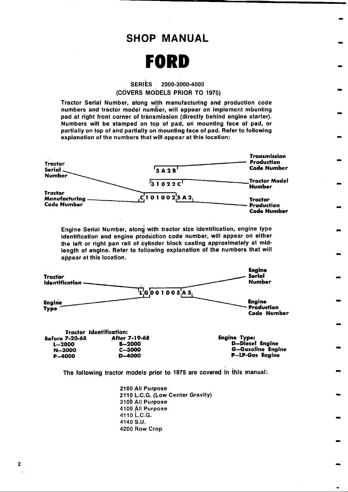
Tractor Serial Number
numbers and tractor model number
pad at right front corner of transmission
Numbers will be stamped on top of pad
partially on top of and partially on mounting face of pad
explanation of the numbers that will appear at this location:
,
along with manufacturing and production code
5A25
PRIOR
will appear on implement mbunting
,
TO 1975)
directly behind engine starter).
(
on mounting face of pad, or
,
.
Refer to following
Transmission
Production
Code Number
31022C
Tractor
Manufacturing
Code Number
Engine Serial Number
Identification and engine production code number
C0 025A2
along with tractor size identification
,
will appear on either
,
the left or right pan rail of cylinder block casting approximately at mid-
Refer to following explanation of the numbers that will
length of engine
.
appear at this location.
Tractor
Identification
L:G:o 0 1 0 0 S:A 5
Engine
Type -
Tractor Identification:
Before 7-20-68
L-2000
N-3000
P-4000
After 7-19-68
B-2000
C-3000
D-4000
Engine Type:
Tractor Model
Number
Tractor
Production
Code Number
engine type
,
Engine
Serial
Number
Engine
Production
Code Number
D-Diesel Engine
G-Gasoline Engine
P-LP-Gas Engine
The following tractor models prior to 1975 are covered in this manual:
2100 All Purpose
2110 L
3106
4100 All
4110 L.C.G.
4140 S.U.
4200 Row Crop
2
C:G. (Low Center Gravity)
.
All Purpose
Purpose
Page 3

By Starting Paragraph)
INDEX
(
BELT PULLEY ................................ 337
BRAKES ......................................308
CARBURETOR, GASOLINE ................... 106
CARBURETOR, LP-GAS ....................... 117
CLUTCH, SINGLE DISC ....................... 184
CLUTCH, DUAL DISC ......................... 185
CLUTCH, POWER TAKE-OFF ................. 332
COOLING SYSTEM:
Radiator .................................... 169
Thermostat ..................................168
Water Pump ................................. 170
DIESEL FUEL SYSTEM:
Bleeding ............................... 129,131
Filters ......................................128
Injection Pump ......................... 151,155
Injector Nozzles ..............................132
Troubleshooting .............................120
DIFFERENTIAL ......................... 284, 300
DIFFERENTIAL LOCK ................... 290,304
ELECTRICAL SYSTEM:
Generator & Regulator ....................... 171
Ignition Distributor .......................... 175
Starting Motor .......................... 172,173
ENGINE:
Assembly, R&R ............................... 66
Camshaft .................................... 87
Connecting Rod Bearings ...................... 95
Crankshaft & Bearings ........................ 96
Crankshaft Oil Seals .......................... 97
Cylinder Head ................................ 68
Cylinders ....................................91
Flywheel, R&R ..............................100
Oil Pan .....................................101
Oil Pump .................................... 103
Pistons & Rings ............................... 89
Piston & Rod Removal ......................... 88
Piston Pins ................................... 94
Rocker Arms ................................. 76
ENGINE
: (
cent)
Timing Gear Cover ............................ 77
Timing Gears ................................. 81
Valve Adjustment
Valves & Seats
Valve Guides
.............................
...............................
Springs ....................... 71
&
72
70
FINAL DRIVE GEARS ......................... 307
FRONT AXLE .............
non-Diesel
GOVERNOR
HYDRAULIC
Adjustments
Lift Cover Assembly
Lift Cylinder
Pump
Pump
Remote Control
Selector Valve ............................... 368
Troubleshooting
IGNITION SYSTEM
LP-GAS SYSTEM
(
LIFT SYSTEM:
.................................344
Overhaul .......................349
,
Piston Type
(
Gear Type
(
Valves .......................370
,
) ..........................
) .......... 366
.............................
...........................
................ . .............
............... L 24,46
) ...................... 164
R&R .................... 347
360
342
174
107
POWER STEERING:
Bleed System
Control Valve ............................. 13,40
Pump ........................................ 12
Steering Gear
System Pressure
POWER TAKE
..........................
......................
...........................
OFF .................. 316, 324, 326
-
10,37,54
13,28,34,58
11,38
REAR AXLE:
Axle Housings
Bearing Adjustment
Remove & Reinstall
Shaft
STEERING
TRANSMISSION (By Type):
,
Auxiliary
Four-Speed
Six-Speed
Eight-Speed
Select-O-Speed
..........................
Manual
(
...................................
...................................201
) .........................
..................................193
.................................210
..............................219
..................... 294, 307
...............
298,307
295, 306
5,28
186
CONDENSED
General
Engine Make ........................
No. of Cylinders .....................
Bore-Inches, Non-Diesel .............
Diesel .............................
Stroke-Inches, Non-Diesel ...........
Diesel .............................
Displacement-Cubic Inches,
Non-Diesel ........................
Diesel .............................
Compression Ratio, Non-Diesel .......
Diesel .............................
TRACTOR SERIES
(Before 7/
2000
Own
3
4.2
4.2
3.8
3.8
158
158
8.0:1
16.5:1
SERVICE DATA
20/68)
3000
Own
3
4.2
4.2
3.8
4.2
158
175
8.0:1
16.5:1
4000
Own
3
4.4
4.4
4.2 3.8
4.4
192
201
8.01:1
16.5:1
TRACTOR SERIES
(After 7/
2000
Own
3
4.2
4.2
3.8
158
158
7.8:1
16.5:1
3000
Own
3
4.2
4.2
3.8
4.2
158
175
7.8:1
16.5:1
19/68)
4000
Own
3
4.4
4.4
4.4
4.4
201
201
7.8:1
16.5:1
3
Page 4
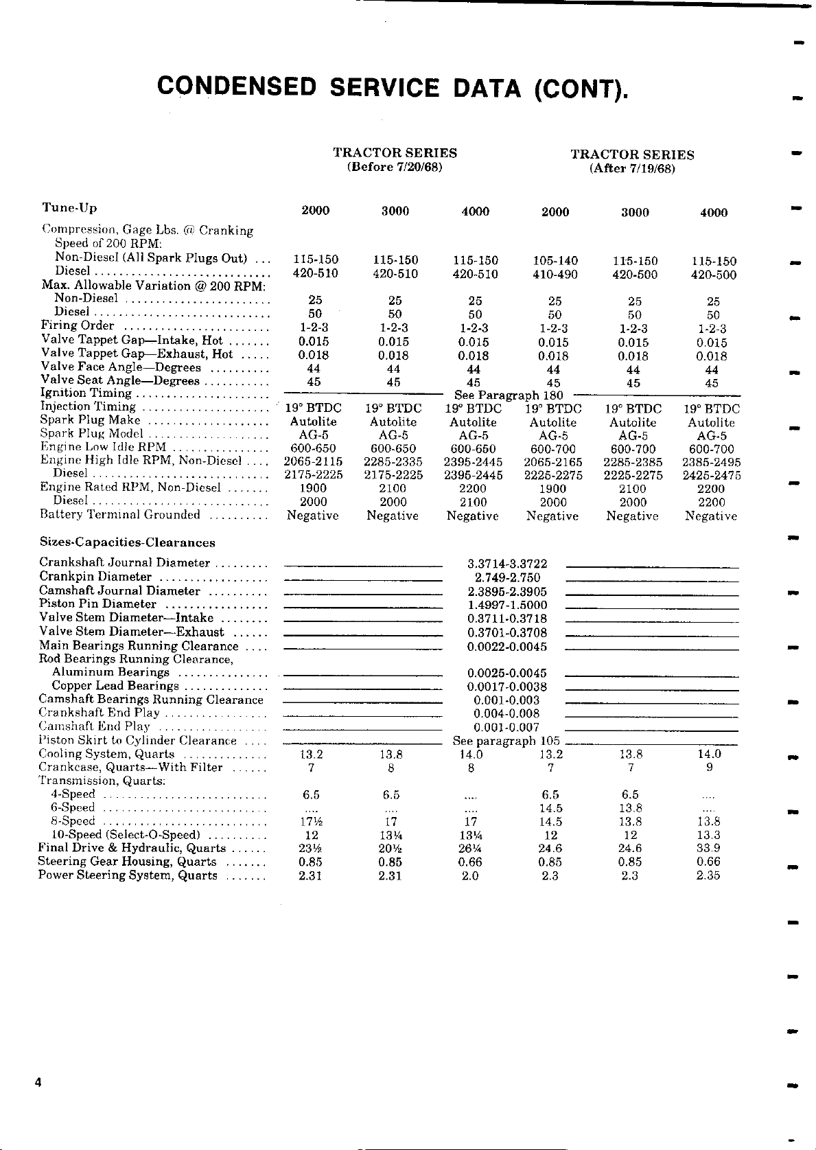
CONDENSED SERVICE
TRACTOR SERIES TRACTOR SERIES
(
Before 7/20/68
DATA (CONT).
) (After 7/
19/68)
Tune-Up
Compression
,
Gage
Lbs. C(
, Cranking
2000 3000 4000 2000 3000 4000
Speed of 200 RPM:
Non-Diesel (All Spark Plugs Out) ...
Diesel .............................
115-150 115-150 115-150 105-140 115-150 115-150
420-510 420-510 420-510 410-490 420-500 420-500
Max. Allowable Variation @ 200 RPM:
Non-Diesel ........................ 25
Diesel ............................. 50
Firing Order ........................ 1-2-3
Valve Tappet Gap-Intake, Hot ....... 0.015
Valve Tappet Gap-Exhaust, Hot ..... 0.018
Valve Face Angle-Degrees .......... 44
Valve Seat Angle-Degrees ........... 45
Ignition Timing ......................
Injection Timing ..................... . 19° BTDC
Spark Plug Make .................... Autolite
Spark Plug Model .................... AG-5
Engine Low Idle RPM ................ 600-650
Engine High Idle RPM, Non-Diesel .... 2065-2115
Diesel ............................. 2175-2225
Engine Rated RPM, Non-Diesel ....... 1900
Diesel ............................. 2000
Battery Terminal Grounded .......... Negative
Sizes-Capacities
Crankshaft
Crankpin Diameter
Camshaft
Piston Pin Diameter
Valve
Valve
Main Bearings Running Clearance ....
Rod Bearings Running
Aluminum Bearings
Copper Lead
Camshaft
Crankshaft End Play .................
Camshaft End Play ..................
Piston Skirt to Cylinder Clearance ....
Cooling System, Quarts ..............
Crankcase, Quarts-With Filter ......
Transmission, Quarts:
4-Speed ........................... 6.5
6-Speed ...........................
8-Speed ........................... 171/2
10-Speed(Select-O-Speed
Final Drive
Steering Gear Housing
Power Steering System, Quarts ....... 2.31
Journal Diameter
Stem Diameter
Stem Diameter
Bearings Running Clearance
-
Clearances
Journal Diameter
..................
.................
-
Intake ........
-
Exhaust ......
Clearance,
Bearings
&
Hydraulic
...............
,
,
Quarts ....... 0.85
.........
..........
..............
13.2 13.8 14.0 13.2 13.8 14.0
7 8 8 7 7 9
) .......... 12
Quarts ...... 231
25 25 25 25 25
50 50 50 50 50
1-2-3 1-2-3 1-2-3 1-2-3 1-2-3
0.015 0.015 0.015 0.015 0.015
0.018 0.018 0.018 0.018 0.018
44 44 44 44 44
45 45 45 45 45
19°BTDC 19° BTDC 19°BTDC 19° BTDC 19°BTDC
Autolite Autolite Autolite Autolite Autolite
AG-5 AG-5 AG-5 AG-5 AG-5
600-650 600-650 600-700 600-700 600-700
2285-2335 2395-2445 2065-2165 2285-2385 2385-2495
2175-2225 2395-2445 2225-2275 2225-2275 2425-2475
2100 2200 1900 2100 2200
2000 2100 2000 2000 2200
Negative Negative Negative Negative Negative
See Paragraph 180
3.3714-3.3722
2.749-2.750
2.3895-2.3905
1.4997-1.5000
0.3711-0.3718
0.3701-0.3708
0.0022-0.0045
0.0025-0.0045
0.0017
0.0038
-
0.001-0.003
0.004-0.008
0.001-0.007
See paragraph 105
6.5
17
131/4
20V2
0.85
2.31
.... 6.5 6.5 ...
.... 14.5 13.8 ....
17 14.5 13.8 13.8
13V4 12 12 13.3
26'4 24
0.66 0.85 0.85 0.66
2.0 2.3 2.3 2.35
.6 24.6 33.9
4
Page 5
2000
3000-4000
-
FRONT SYSTEM AND STEERING
4110 & 4140 S.U.)
(MODELS 2100
2110
,
,
3100
,
Paragraphs 1-6
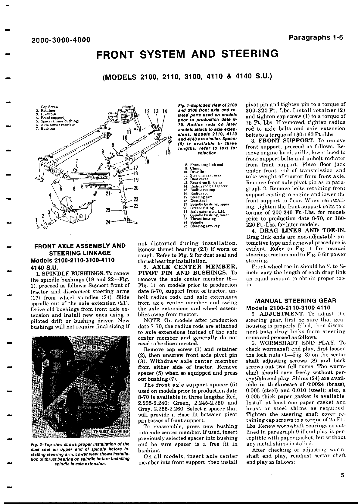
1. Cap Screw
2. Retainer
3. Pivotpin
4. Front support
(
5. Spacer
6. Axle center member
7. Bushing
inner bushing)
FRONT AXLE ASSEMBLY AND
STEERING LINKAGE
3100-4110
2110
Models 2100
-
-
4140 S.U.
1. SPINDLE BUSHINGS. To renew
the spindle bushings (19 and 22-Fig.
1), proceed as follows: Support front of
tractor and disconnect steering arms
(17) from wheel spindles (24). Slide
spindle out of the axle extension (21).
Drive old bushings from front axle extension and install new ones using a
piloted drift or bushing driver. New
bushings will not require final sizing if
Lower
extension.
installation of the
view show,
Fig. 2-Top view shows proper
dust seal on
stalling steering
tion of thrust bearing on spindle before
upper end of spindle before in-
arm.
spindle In axle
installa-
installing
pivot pin and tighten pin to a torque of
300-320 Ft.-Lbs. Install retainer (2)
and tighten cap screw (1) to a torque of
75 Ft.-Lbs. If removed, tighten radius
rod to axle bolts and axle extension
bolts to a torque of 130-160 Ft.-Lbs.
front support, proceed as follows: Re-
move engine hood, grille, lower hood to
rods
similar
to text for
and remodels
on
on later
.
of 2100
Spacer
Exploded view
-
Fig. 1
and
3100 front axle
lated parts
prior to production date 8-
70. Radius
models attach to axle exten-
sions
and
(5) is available in three
lengths;
used
Models 2110, 4110
.
4140 are
refer
selection.
front support bolts and unbolt radiator
8. l' ont drag link end
9. Clamp
10. [)rag link
11. Steering
12. Dust c.var
lI Rear dreg link and
14. Radius
15. Radius rod cap
16. Radius red
12 Steering arm
18. Dust Seal
19. Spindle bushing, upper
20. Grease fitting
21. Axle extension, L.H.
22. S indle bushing, lower
23. Thrust bearing
24. Spindle
25. Steering arm key
gear easy.
red ball spacer
from front support. Place floor jack
under front end of transmission and
take weight of tractor from front axle.
Remove front axle pivot pin as in paragraph 2. Remove bolts retaining front
support casting to engine and tower the
front support to floor. When reinstalling, tighten the front support bolts to a
torque of 200-240 Ft.-Lbs. for models
prior to production date 8-70, or 180220 Ft.-Lbs. for later models.
Drag link ends are non-adjustable au-
not distorted during installation.
Renew thrust bearing (23) if worn or
rough. Refer to Fig. 2 for dust seal and
thrust bearing installation.
2. AXLE CENTER
MEMBER,
PIVOT PIN AND BUSHINGS. To
remove the axle center member (6Fig. 1), on models prior to production
tomotive type and renewal procedure is
evident. Refer to Fig. 1 for manual
steering tractors and to Fig. 5 for power
steering.
inch; vary the length of each drag link
an equal amount to obtain proper toe-
in.
date 8-70, support front of tractor, unbolt radius rods and axle extensions
from axle center member and swing
the axle extensions and wheel assem-
Models 2100-2110
blies away from tractor.
NOTE: On models after production
date 7-70, the radius rods are attached
to axle extensions instead of the axle
center member and generally do not
steering gear, first be sure that gear
housing is properly filled, then disconnect both drag links from steering
arms and proceed as follows:
need to be disconnected.
Remove cap screw (1) and retainer
(2), then unscrew front axle pivot pin
(3). Withdraw axle center member
from either side of tractor. Remove
5) when so equipped and press
spacer
(
out bushing (7).
The front axle support spacer (5)
used on models prior to production date
8-70 is available in three lengths: Red,
2.235-2.240; Green, 2.245-2.250 and
Grey, 2.255-2.260. Select a spacer that
will provide a close fit between pivot
pin bosses of front support.
To reassemble, press new bushing
into axle center member. If used, insert
previously selected spacer into bushing
and be sure spacer is a free fit in
check wormshaft end play, first loosen
the lock nuts (1-Fig. 3) on the sector
shaft adjusting screws
screws out two full turns. The wormshaft should turn freely without perceptible end play. Shims (24) are avail-
able in thicknesses of 0.0024 (brass),
0.005 (steel) and 0.010 (steel); also, a
0.005 thick paper gasket is available.
Install at least one paper gasket and
brass or steel shims as required.
Tighten the steering shaft cover retaining cap screws to a torque of 25 Ft.-
Lbs. Renew wormshaft bearings as outlined in paragraph 9 if end play is perceptible with paper gasket, but without
any metal shims installed.
bushing.
On all models, insert axle center
member into front support, then install
shaft end play, readjust sector shaft
end play as follows:
3. FRONT SUPPORT. To remove
4. DRAG LINKS AND TOE-IN.
Front wheel toe-in should be Y4 to 'A-
MANUAL STEERING GEAR
3100-4110
5. ADJUSTMENT. To adjust the
6. WORMSHAFT END PLAY. To
After checking or adjusting worn-
-
(8) and back
5
Page 6
Paragraphs 7-9
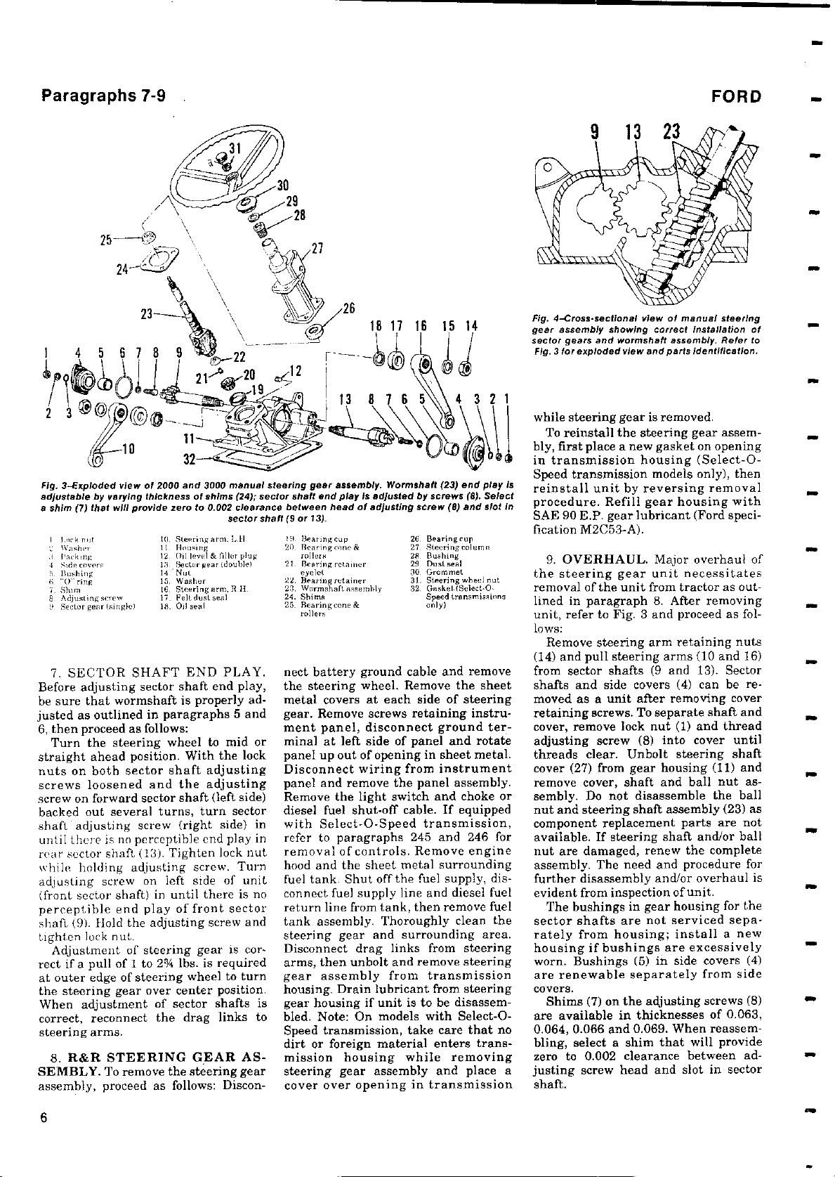
Fig. 3-Exploded
adjustable
a shim(7) that
I ,rknut
d parkin,
4 Sidecovere
5. Hushing
6 "0` ring
.. Shun
8. Adjust, ngsrrew
9. Sector gear I urn e)
7. SECTOR SHAFT END PLAY.
Before adjusting sector shaft end play,
be sure that wormshaft is properly ad-
justed as outlined in paragraphs 5 and
6, then proceed as follows:
Turn the steering wheel to mid or
straight ahead position. With the lock
nuts on both sector shaft adjusting
screws loosened and the adjusting
screw on forward sector shaft (left side)
backed out several turns, turn sector
shaft adjusting screw (right side) in
until there is no perceptible end play in
rear sector shaft (13). Tighten lock nut
while holding adjusting screw. Turn
adjusting screw on left side of unit
(front sector shaft) in until there is no
perceptible end play of front sector
shaft (9). Hold the adjusting screw and
tighten lock nut.
Adjustment of steering gear is cor-
rect if a pull of 1 to 2%4 lbs. is required
at outer edge of steering wheel to turn
the steering gear over center position.
When adjustment of sector shafts is
correct, reconnect the drag links to
steering arms.
8. R&R STEERING GEAR ASSEMBLY. To remove the steering gear
assembly, proceed as follows: Discon-
view of 2000 and 3000 manual steering
by varying
thicknessof shims (24);
will provide
zero to 0
10
.
11. HnusIFg
1 2 Oiilevel & filler plug
18. Bettor pear (doublet21Hearing retainer
14, Nut
1.5, Washer
16.Steeringarm,Rll-
17. Felt dust seal
IS. Oil seal
Steering arm
.
002
clearance
sector
.
1,11
gear
shaft end play Is adjusted
sector
betweenhead of adjusting screw(8) and slot In
9 or 13).
shaft
(
14.
20
22.
23.
24.
25.
assembly
Ilearingeup
Bearingrvne&
rnl lers
t
Hearing retainer
Wormshaft nseembly
Shims
Rearing cure &
rollers
Wormshaft(23) end play is
.
by screws(8). Select
Bearing cup
26
.
27. Steeringeolumn
28
Bushing
Dustseal
29
Grommet
30
31. Steering wheel nut
Geekel (select-
32.
0-
Speed transmissions
only)
nect battery ground cable and remove
the steering wheel. Remove the sheet
metal covers at each side of steering
gear. Remove screws retaining instrument panel, disconnect ground terminal at left side of panel and rotate
panel up out of opening in sheet metal.
Disconnect wiring from instrument
panel and remove the panel assembly.
Remove the light switch and choke or
diesel fuel shut-off cable. If equipped
with Select-O-Speed transmission,
refer to paragraphs 245 and 246 for
removal of controls. Remove engine
hood and the sheet metal surrounding
fuel tank. Shut off the fuel supply, disconnect fuel supply line and diesel fuel
return line from tank, then remove fuel
tank assembly. Thoroughly clean the
steering gear and surrounding area.
Disconnect drag links from steering
arms, then unbolt and remove steering
gear assembly from transmission
housing. Drain lubricant from steering
gear housing if unit is to be disassembled. Note: On models with Select-OSpeed transmission, take care that no
dirt or foreign material enters transmission housing while removing
steering gear assembly and place a
cover over opening in transmission
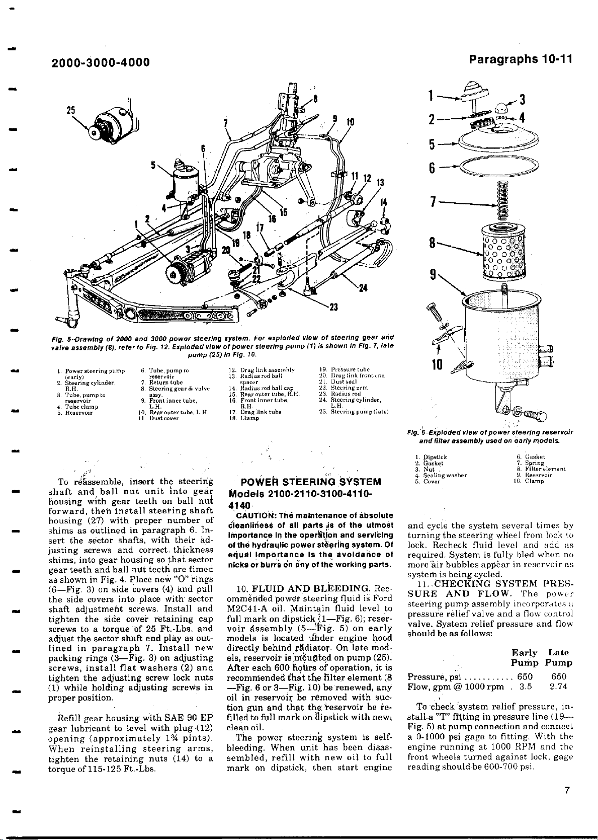
Fig.
4-Cross-
gear assembly
sector
Fig. 3 for exploded
sectional view
gears and wormshaft assembly
showing
view and parts Identification.
of manual steering
correct
Installation of
while steering gear is removed.
To reinstall the steering gear assembly, first place a new gasket on opening
in transmission housing (Select-OSpeed transmission models only), then
reinstall unit by reversing removal
procedure. Refill gear housing with
SAE 90 E.P. gear lubricant (Ford specification M2C53-A).
9. OVERHAUL. Major overhaul of
the steering gear unit necessitates
removal of the unit from tractor as outlined in paragraph 8. After removing
unit, refer to Fig. 3 and proceed as follows:
Remove steering arm retaining nuts
(14) and pull steering arms (10 and 16)
from sector shafts (9 and 13). Sector
shafts and side covers (4) can be removed as a unit after removing cover
retaining screws. To separate shaft and
cover, remove lock nut (1) and thread
adjusting screw (8) into cover until
threads clear. Unbolt steering shaft
cover (27) from gear housing (11) and
remove cover, shaft and ball nut assembly. Do not disassemble the ball
nut and steering shaft assembly (23) as
component replacement parts are not
available. If steering shaft and/or ball
nut are damaged, renew the complete
assembly. The need and procedure for
further disassembly and/or overhaul is
evident from inspection of unit.
The bushings in gear housing for the
sector shafts are not serviced separately from housing; install a new
housing if bushings are excessively
worn. Bushings (5) in side covers (4)
are renewable separately from side
covers.
Shims (7) on the adjusting screws (8)
are available in thicknesses of 0.063,
0.064, 0.066 and 0.069. When reassembling, select a shim that will provide
zero to 0.002 clearance between ad-
justing screw head and slot in sector
shaft.
FORD
.
Refer to
6
Page 7
2000
3000-4000
-
Paragraphs 10-11
M
Fig. 5-Drawing
valve
assembly
I Power steering pump
(early)
2. Steering cylinder,
R
H
.
.
3. Tube, pump to
reservoir
Tube clamp
4
.
5. Reservoir
of 2000
(
8),
refer to Fig.
3000
and
12.Exploded
6. Tune, pump to
reservoir
7. Return tube
8. Steering
tossy
9. Front inner tube,
L.H.
10. Rose mar tube, L. H.
ll. Dust cover
To rehssemble, insert the steering
shaft and ball nut unit into gear
housing with gear teeth on ball nut
forward, then install steering shaft
housing (27) with proper number of
shims as outlined in paragraph 6. Insert the sector shafts, with their ad-
justing screws and correct, thickness
shims, into gear housing so that sector
gear teeth and ball nut teeth are timed
as shown in Fig. 4. Place new "0" rings
(6-Fig. 3) on side covers (4) and pull
the side covers into place with sector
shaft adjustment screws. Install and
tighten the side cover retaining cap
screws to a torque of 25 Ft.-Lbs. and
adjust the sector shaft end play as outlined in paragraph 7. Install new
packing rings (3-Fig. 3) on adjusting
screws, install flat washers (2) and
tighten the adjusting screw lock nuts
(1) while holding adjusting screws in
proper position.
Refill gear housing with SAE 90 EP
gear lubricant to level with plug (12)
opening (approximately 1%4 pints).
When reinstalling steering arms,
tighten the retaining nuts (14) to a
torque of 115-125 Ft.-Lbs.
power steering
pump
our & valve
For exploded view of steering
system
view of power steering pump
25) in Fig. 10.
(
.
12. Drag link asscmhly
13 Radius tad ball
14. Radius rod ball cap
15. Rear outer tube, R.H.
t6. Front inner tube,
R.H.
17. Drag link tube
18. Clamp
(
1) is shown
POWER STEERING SYSTEM
Models 2100
-2110-3100-4110-
4140
CAUTION:
dleanliness of all parts
Importance In the operilitlon and servicing
of the hydraylic power steering system. Of
equal Importance Is the avoidance of
nicks or burrs on any of the working parts.
10. FLUID AND BLEEDING. Recommended power steering fluid is Ford
M2C41-A oil. Maintain fluid level to
full mark on dipstick ,it-Fig. 6); reservoir assembly (5-Fig. 5) on early
models is located tinder engine hood
directly behind,ptidiator. On late models, reservoir is nlburlted on pump (25).
After each 600 hgiirs of operation, it is
recommended that the filter element (8
-Fig. 6 or 3-Fig. 10) be renewed, any
oil in reservoir be removed with suction gun and that the, reservoir be refilled to full mark on 'dipstick with new;
clean oil.
The power steering system is selfbleeding. When unit has been disassembled, refill with new oil to full
mark on dipstick, then start engine
The maintenance of absolute
gear and
In Fig. 7, late
19.
Ore'vsure tube
Drag link fruit tend
20.
21. Duatseal
22 .
Steering arm
23. Radius ad
24. Steering cylinder,
L.H.
25. Steering pump (late)
s of the utmost
J
Fig.-6-Exploded
and filter assembly usedonearly models.
1. (lipstick
2. Gasket
3. Nut
4. Sealing washer
5. Cover
view of power steering
reservoir
6. Gasket
7. Spring
8. Filter element
9. Reservoir
10 Clamp
and cycle the system several times by
turning the steering wheel from lock to
lock. Recheck fluid level and add as
required. System is fully bled when no
more 'air bubbles appear in reservoir as
systerh is being cycled.
11.. CHECKING SYSTEM PRES-
SURE AND FLOW. The power
steering pump assembly incorporates a
pressure relief valve and a flow control
valve. System relief pressure and flow
should be as follows:
Early Late
Pump Pump
Pressure, psi ........... 650 650
Flow, gpm @ 1000 rpm . 3.5 2.74
To check 'system relief pressure,in-
stall..a "T" fitting in pressure line (19Fig. 5) at pump connection and connect
a 0-1000 psi gage to fitting. With the
engine running at 1000 RPM and the
front wheels turned against lock, gage
reading should be 600-700 psi.
7
Page 8
Paragraph 12
36
FORD
'0' RINGS
r
23
35 34 I
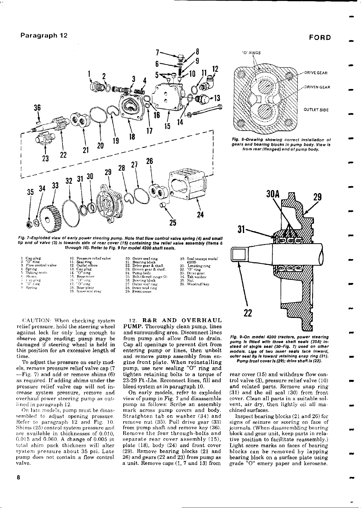
Fig. 7-Exploded
tip end of valve
I Cap plug
2. "0 ring
3. Flow control valve
4 Spring
5 Tubing .-Tt,
,Shims
Cap ping
0 ring
9 Spring
22
31 3,
29
view of early power steering pump
(
3) Is towards side of rear
through 10). Refer
10. Pressure reliefvalve
11.
Seal ring
12. Outlet elbow
13. Cap plug
14 "0" ring
15 Rearcover
10. !(.. ring
17 "0" ring
18 _ Rear plate
19. Inner seal ring
29 2
cover
Fig.
to
26
.
Note that
(
15) containing the relief valve
9 for
20. Outer seal ring
21. Bearing block
22. Drive or & shaft
23. Driven gear & shaft
24. Pump body
25 Bolt(dowelt rings 12(
26. Bearing black
27. Outer seal ring
28- Inner seal ring
29 Frontmver
model
flow control
4200 shaft
seals.
24
25
valve
(
spring
4) and small
assembly(Items 6
30. Seal (except model
4200)
31. Locating ring
32 '0" ring
33. Drive gear
84. Tab washer
35. Nut
36. Woodruff key
Fig. 8-Drawing showing
gears and bearing blocks
from rear
(
flanged
correct
Installation of
In pump body. View is
) end of pump body.
CAUTION: When
relief pressure
,
checking system
hold the steering wheel
against lock for only long enough to
observe gage reading; pump may be
damaged if steering wheel is held in
this position for an excessive length of
time.
To adjust the pressure on early mod-
els, remove pressure relief valve cap (7
-Fig. 7
as required
)
and add or remove shims (6)
.
If adding shims under the
pressure relief valve cap will not increase system pressure
,
remove and
overhaul power steering pump as outlined in paragraph 12.
On late models,
sembled to
Refe
r to paragraph 12 and Fig. 10.
Shims (
25) control system pressure and
pump must be disas-
adjust opening pressure.
are available in thicknesses of 0.010,
0.015 and 0.060
.
A change of 0.005 in
total shim pack thickness will alter
system pressure about 35 psi. Late
pump does not contain a flow control
valve.
8
12. R&R AND OVERHAUL
PUMP. Thoroughly clean pump, lines
and surrounding area. Disconnect lines
from pump and allow fluid to drain.
Cap all openings to prevent dirt from
entering pump or lines, then unbolt
and remove pump assembly from engine front plate. When reinstalling
pump, use new sealing "0" ring and
tighten retaining bolts to a torque of
23-29 Ft.-Lbs. Reconnect lines, fill and
bleed system as in paragraph 10.
On early models, refer to exploded
view of pump in Fig. 7 and disassemble
pump as follows: Scribe an assembly
mark across pump covers and body.
Straighten tab on washer (34) and
remove nut (35). Pull drive gear (33)
from pump shaft and remove key (36).
Remove the four through-bolts and
separate rear cover assembly (15),
plate (18), body (24) and front cover
(29). Remove bearing blocks (21 and
26) and gears (22 and 23) from pump as
a unit. Remove caps (1, 7 and 13) from
Fig,
pump Is fitted with
stead
models
outer seal
model 4200
9-On
of single seal (30
Lips of two
.
lip Is toward retaining snap ring (31).
Pump front cover Is
tractors
shaft
three
Fig.
-
Innerseals face
29);
drive shaft is (22).
(
,
power steering
seals
7) used on
rear cover (15) and withdraw flow control valve (3), pressure relief valve (10)
and related parts. Remove snap ring
(31) and the oil seal (30) from front
cover. Clean all parts in a suitable solvent, air dry, then lightly oil all machined surfaces.
Inspect bearing blocks (21 and 26) for
signs of seizure or scoring on face of
journals. (When disassembling bearing
block and gear unit, keep parts in rela-
tive position to facilitate reassembly.)
Light score marks on faces of bearing
blocks can be removed by lapping
bearing block on a surface plate using
grade "0" emery paper and kerosene.
(
30A) in-
other
Inward,
Page 9
2000
3000-4000
-
Paragraphs 13-16
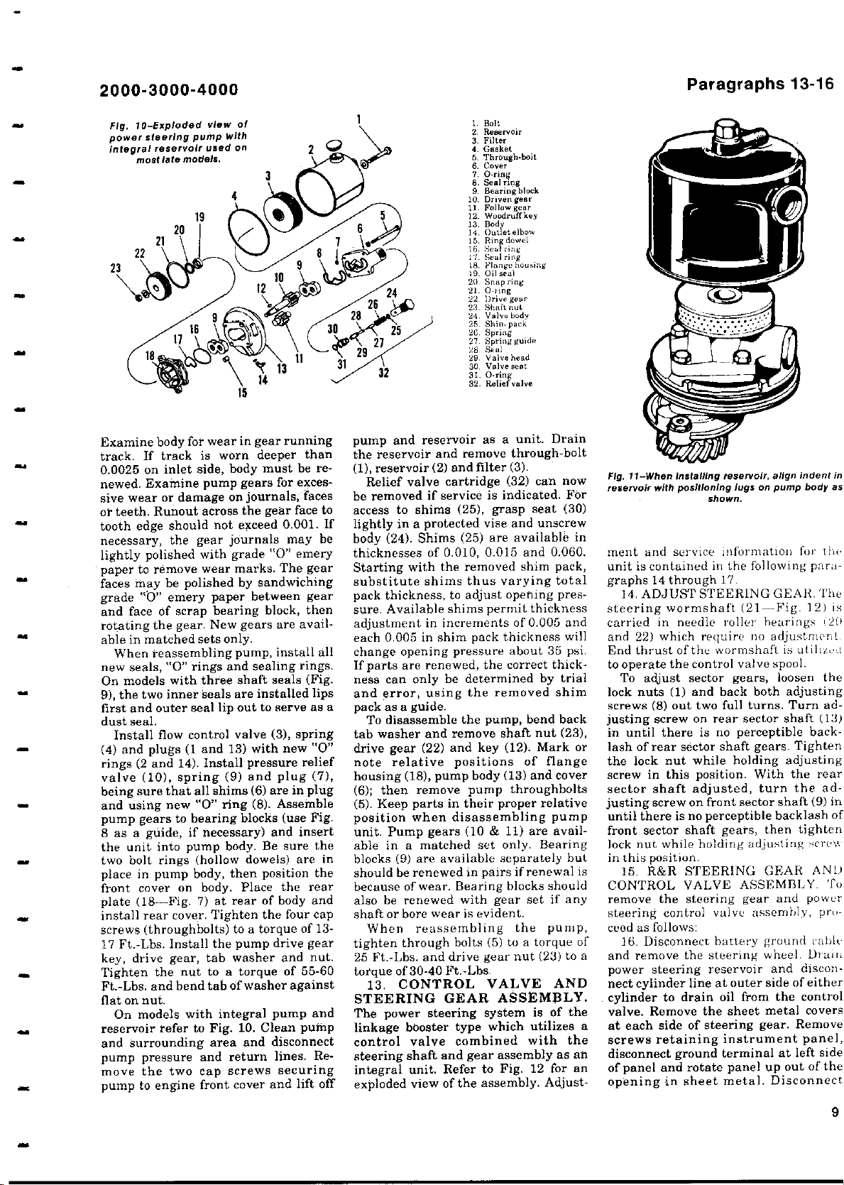
Fig. 10-Exploded
steering
power
integral reservoir used
most
late
view of
pump With
models.
on
Examine body for wear in gear running
track. If track is worn deeper than
0.0025 on inlet side, body must be renewed. Examine pump gears for exces-
sive wear or damage on journals, faces
or teeth. Runout across the gear face to
tooth edge should not exceed 0.001. If
necessary, the gear journals may be
lightly polished with grade "0" emery
paper to remove wear marks. The gear
faces may be polished by sandwiching
grade "0" emery paper between gear
and face of scrap bearing block, then
rotating the gear. New gears are avail-
able in matched sets only.
When reassembling pump, install all
new seals, "0" rings and sealing rings.
On models with three shaft seals (Fig.
are installed lips
9), the two inner
seals
first and outer seal lip out to serve as a
dust seal.
Install flow control valve (3), spring
(4) and plugs (1 and 13) with new "0"
rings (2 and 14). Install pressure relief
valve (10), spring (9) and plug (7),
being sure that all shims (6) are in plug
and using new "0" ring (8). Assemble
pump gears to bearing blocks (use Fig.
8 as a guide, if necessary) and insert
the unit into pump body. Be sure the
two bolt rings (hollow dowels) are in
place in pump body, then position the
front cover on body. Place the rear
plate (18-Fig. 7) at rear of body and
install rear cover. Tighten the four cap
screws (throughbolts) to a torque of 13-
17 Ft.-Lbs. Install the pump drive gear
key, drive gear, tab washer and nut.
Tighten the nut to a torque of 55-60
Ft.-Lbs. and bend tab of washer against
flat on nut.
On models with integral pump and
reservoir refer to Fig. 10. Clean pump
and surrounding area and disconnect
pump pressure and return lines. Remove the two cap screws securing
pump to engine front cover and lift off
1. Bolt
2, Reservoir
3. Filter
4. Gaeket
5. Through-bolt
6. Cover
7. O-ring
8. Seal nng
9. Bearing block
10. Driven gear
1I. Follow gear
12. Woodruffkey
13. Body
14. Outlet elbow
15. Ring dowel
16..Seal ring
17 . Seal ring
16. Flange'casing
10. Oil seal
20. Snap ring
21. O-ring
22 Drive gear
23, Shot, not
24. Valve hody
25. Shin, park
26. Spring
27 . Spring guide
28 Seal
29. Valve head
30. valve seat
31. O-ring
32. Relief valve
pump and reservoir as a unit. Drain
the reservoir and remove through-bolt
(1), reservoir (2) and filter (3).
Relief valve cartridge (32) can now
be removed if service is indicated. For
access to shims (25), grasp seat (30)
lightly in a protected vise and unscrew
body (24). Shims (25) are available in
thicknesses of 0.010, 0.015 and 0.060.
Starting with the removed shim pack,
substitute shims thus varying total
pack thickness, to adjust opening pressure. Available shims permit thickness
adjustment in increments of 0.005 and
each 0.005 in shim pack thickness will
change opening pressure about 35 psi.
If parts are renewed, the correct thickness can only be determined by trial
and error, using the removed shim
pack as a guide.
To disassemble the pump, bend back
tab washer and remove shaft nut (23),
drive gear (22) and key (12). Mark or
note relative positions of flange
housing (18), pump body (13) and cover
(6); then remove pump throughbolts
(5). Keep parts in their proper relative
position when disassembling pump
unit. Pump gears (10 & 11) are available in a matched set only. Bearing
blocks (9) are available separately but
should be renewed in pairs if renewal is
because of wear. Bearing blocks should
also be renewed with gear set if any
shaft or bore wear is evident.
When reassembling the pump,
tighten through bolts (5) to a torque of
25 Ft.-Lbs. and drive gear nut (23) to a
torque of 30-40 Ft.-Lbs.
13, CONTROL VALVE AND
STEERING GEAR ASSEMBLY.
The power steering system is of the
linkage booster type which
control valve combined with the
steering shaft and gear assembly as an
integral unit. Refer to Fig. 12 for an
exploded view of the assembly. Adjust-
utilizes a
align indent in
Fig.
11
reservoir with positioning lugs
-
When
Installing
shown.
reservoir
,
pump body as
on
ment and service information for thr
unit is contained
graphs 14
in the following para-
through 17.
14. ADJUST STEERING GEAR. The
steering
carried in
and 22
End thrust
to operate the control
To adjust sector gears
lock nuts
screws
wormshaft (21-Fig. 12) is
needle roller hearings i20
) which require no adjustment
of the wormshaft is utiliz,,il
valve spool.
loosen the
1) and back both adjusting
(
8) out two full turns. Turn ad-
(
,
justing screw on rear sector shaft (13)
in until there is no perceptible backlash of rear sector shaft gears.
the lock nut while holding adjusting
screw in this position
sector shaft adjusted
. With the rear
,
turn the ad-
justing screw on front sector shaft (9) in
until there is no perceptible backlash of
then tighten
front sector shaft gears
,
lock nut while holding adjusting scre,'
in this position.
15. R&R
STEERING GEAR AND
CONTROL VALVE ASSEMBLY. To
remove the steering
steering
control valve assembly, prt,-
gear and power
ceod as follows:
16. Disconnect
and remove
battery ground cable
the steering wheel. Drai1:
power steering reservoir and disconnect cylinder line at outer side of either
cylinder to drain oil from the control
Remove the sheet metal covers
.
valve
at each side of steering gear
.
screws retaining instrument panel,
disconnect ground terminal at left side
of panel and rotate panel up out of the
opening in sheet metal. Disconnect
Tighten
Remove
9
Page 10
Paragraphs 17-20
FORD
1 3 4
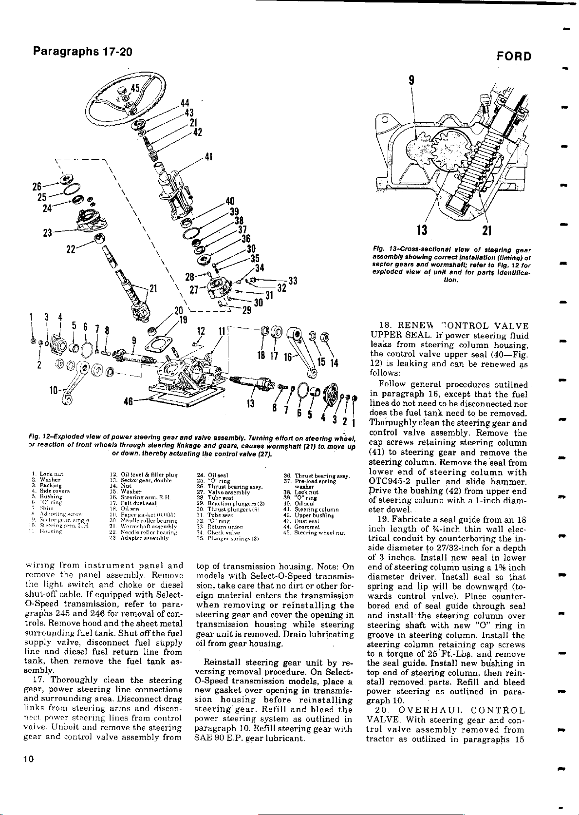
Fig. 12-Exploded view of power steering
or reaction of front wheels through
I buck nut 12
2. Washer 13
3. Packing 14. Nut
4. side covers 15. Washer
5. slushing 36
G. "0 "ring 17.
Shim 13. Ollaeal
S Adma-ring rvcw' IH. Paper "Ilk" 10 1051
9. Seeni'gea g 20. Needlr rollerben ink
Streri gnnnl..H. 21. Warns hallasacmbl
Housing 22 Needle roll crbaaring
wiring from instrument panel and
remove the panel assembly. Remove
the light switch and choke or diesel
shut-off cable. If equipped with SelectO-Speed transmission, refer to para-
graphs 245 and 246 for removal of controls. Remove hood and the sheet metal
surrounding fuel tank. Shut off the fuel
supply valve, disconnect fuel supply
line and diesel fuel return line from
tank, then remove the fuel tank as-
sembly.
17. Thoroughly clean the steering
gear, power steering line connections
and surrounding area. Disconnect drag
links from steering arms and disconnect power steering lines from control
valve. Unbolt and remove the steering
gear and control valve assembly from
or down,
.
Oil level & filler plug
.
Sector gear,double
.
Steering arm, Rit
Felt dust seal
23. Adapter assembly
gear and valve
steering
thereby
linkage and gears
actuating the control valve (27).
24. Oil seal
25. "0" ring
26. Thrust bearing asay,
27. Valve assembly
.
28. Tube seat
29. Reaction plungers (2)
30. Thrust plungers(61
31. Tubes,-at
32. "0"ring
33. Return union
34. Check valve
35. Plunger springs (.3)
top of transmission housing. Note: On
models with Select-O-Speed transmission, take care that no dirt or other foreign material enters the transmission
when removing or reinstalling the
steering gear and cover the opening in
transmission housing while steering
gear unit is.removed. Drain lubricating
oil from gear housing.
versing removal procedure. On SelectO-Speed transmission
new gasket over opening in transmission housing before reinstalling
steering gear. Refill and bleed the
power steering system as outlined in
paragraph 10. Refill steering gear with
SAE 90 E.P. gear lubricant.
assembly. Turning
,
causes
effort
on steering
wormshaft
38. Thrust bearing easy.
37. Pre.
.her
38. Lockout
39. "0" ring
40. Oil seal
41. Steeringculumn
42. Upper bushing
43 Dust seal
44. Grommel
45. Steering w heel nut
Reinstall steering gear unit by re-
models,place a
x
4 3 2 1
(21) to move
lad spring
wheel,
up
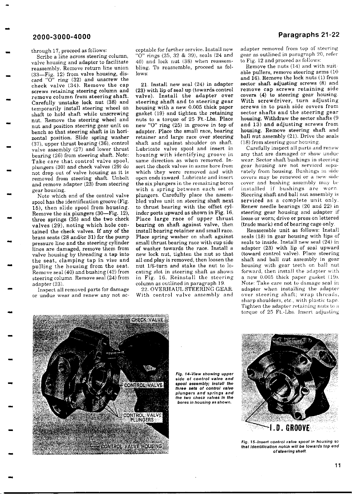
13
Fig.
13-Cross
-
assembly showing
sector gears
exploded view of unit and for parts Identfllca-
18. RENEFA
UPPER SEAL.
sectional
correct
and wormahaft
tion.
7ONTROL VALVE
If power steering fluid
21
view of steering gear
Installation
;
refer
to
leaks from steering column housing,
the control valve upper seal (40-Fig.
12) is leaking and can be renewed as
follows:
Follow general procedures outlined
in paragraph 16, except that the fuel
lines do not need to be disconnected nor
does the fuel tank need to be removed.
Thoroughly clean the steering gear and
control valve assembly
.
Remove the
cap screws retaining steering column
(41) to steering gear and remove the
steering column
lower
-
end of steering column with
.
Remove the seal from
OTC945-2 puller and slide hammer.
prive
the bushing
(
42) from upper end
of steering column with a 1-inch diameter dowel.
19. Fabricate a seal guide from an 18
inch
length of %-inch
thin
wall electrical conduit by counterboring the inside diameter to 27
of 3 inches
.
/
32-inch for a depth
Install new seal in lower
end of steering column using a 1% inch
diameter driver. Install seal so that
spring and lip will be downward (towards control valve
).
Place counterbored end of seal guide through seal
and install
'
the steering column over
steering shaft with new "0" ring in
groove in steering column
.
Install the
steering column retaining cap screws
to a torque of 25 Ft
.-
Lbs. and remove
the seal guide.Install new bushing in
top end of steering column
,
then reinstall removed parts. Refill and bleed
power steering as outlined in paragraph 10.
20. OVERHAUL CONTROL
VALVE. With
steering gear and con-
trol valve assembly removed from
tractor as outlined in paragraphs 15
(
timing) of
Fig. 12 for
w
•
M
10
Page 11
2000
3000-4000
-
Paragraphs 21-22
through 17, proceed as follows:
Scribe a line across steering column,
valve housing and adapter to facilitate
reassembly. Remove return line union
(33-Fig. 12) from valve housing, dis-
card "0" ring (32) and unscrew the
check valve (34). Remove the cap
screws retaining steering column and
remove column from steering shaft.
Carefully unstake lock nut (38) and
temporarily install steering wheel on
shaft to hold shaft while unscrewing
nut. Remove the steering wheel and
nut and position steering gear unit on
bench so that steering shaft is in hori-
zontal position. Slide spring washer
(37), upper thrust bearing (36), control
valve assembly (27) and lower thrust
bearing (26) from steering shaft. Note:
Take care that control valve spool,
plungers (30) and check valves (29) do
not drop out of valve housing as it is
removed from steering shaft. Unbolt
and remove adapter (23) from steering
gear housing.
Note which end of the control valve
spool has the identification groove (Fig.
15), then slide spool from housing.
Remove the six plungers (30-Fig. 12),
three springs (35) and the two check
valves (29), noting which hole contained the check valves. If any of the
brass seats (28 and/or 31) for the pump
pressure line and the steering cylinder
lines are damaged, remove them from
valve housing by threading a tap into
the seat, clamping tap in vise and
pulling the housing from the seat.
Remove seal (40) and bushing (42) from
steering column. Remove seal (24) from
adapter (23).
Inspect all removed parts for damage
or undue wear and renew any not ac-
ceptable for further service. Install new
"0" rings (25, 32 & 39), seals (24 and
40) and lock nut (38) when reassembling. To reassemble, proceed as follows:
21. Install new seal (24) in adapter
(23) with lip of seal up (towards control
valve). Install the adapter over
steering shaft and to steering gear
housing with a new 0.005 thick paper
gasket (19) and tighten the retaining
nuts to a torque of 25 Ft.-Lbs. Place
new "0" ring (25) in groove in top of
adapter. Place the small race, bearing
retainer and large race over steering
shaft and against shoulder on shaft.
Lubricate valve spool and insert in
housing with identifying groove in
same direction as when removed. Insert the check valves in same bore from
which they were removed and with
open ends inward. Lubricate and insert
the six plungers in the remaining bores
with a spring between each set of
plungers. Carefully place the assembled valve unit on steering shaft next
to thrust bearing with the offset cylinder ports upward as shown in Fig. 16.
Place large race of upper thrust
bearing on shaft against valve, then
install bearing retainer and small race.
Place spring washer on shaft against
small thrust bearing race with cup side
of washer towards the race. Install a
new lock nut, tighten the nut so that
all end play is removed, then loosen the
nut 1/6-turn and stake the nut to locating slot in steering shaft as shown
in Fig. 16. Reinstall the steering
column as outlined in paragraph 19.
22. OVERHAUL STEERING GEAR.
With control valve assembly and
adapter removed from top of steering
gear as outlined in paragraph 20, refer
to Fig. 12 and proceed as follows:
Remove the nuts (14) and with suit-
remove steering
able pullers
and 16). Remove
,
the lock nuts (1) from
sector shaft adjusting screws (8) and
remove cap screws retaining side
covers
With
screws in to
sector shafts and
housing
and 13
housing
ball nut assembly
4) to steering gear housing.
(
screwdriver
push
, turn adjusting
side covers from
the steering gear
. Withdraw
and adjusting screws from
)
Remove steering
.
the sector
(21). Drive the seals
(18) from steering gear housing.
Carefully inspect all parts and renew
any that are damaged or show undue
wear. Sector shaft bushings in steering
gear housing are not serviced separately from housing. Bushings in side
covers may be renewed or a new side
cover and bushing assembly may be
installed if bushings are worn.
Steering shaft and ball nut assembly is
serviced
Renew needle bearings
steering gear housing
loose or worn
(
trade
Reassemble
seals
seals to inside
as a complete unit only.
; drive or press on lettered
end of bearing
mark)
unit as follows:
18) in gear
(
. Install new seal (24) in
(20 and 22) in
and adapter if
housing with lips of
adapter (23) with lip of seal upward
(toward control valve). Place steering
shaft and ball nut assembly in gear
housing with gear teeth on ball nut
forward, then install the adapter with
a new 0.005 thick paper gasket (19).
Note: Take care not to damage seal in
adapter when installing the adapter
over steering shaft; wrap threads,
sharp shoulders, etc., with plastic tape.
Tighten the adapter retaining nuts to a
torque of 25 Ft.-Lbs. Insert adjusting
arms (10
shafts (9
shaft and
cage only.
Install
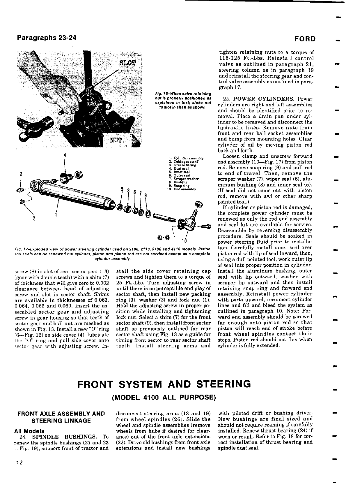
Fig. 14-View
side of control
spool assembly;Install
three sets of control
plungers and springs and
the two check
bores
showing
in housing
valve and
valves in the
as shown.
upper
valve
the
Fig. 15-Insert
that
identification
control
notch
of steering
valve
will be
spool in housing
towards
shaft.
top end
so
11
Page 12
Paragraphs 23-24
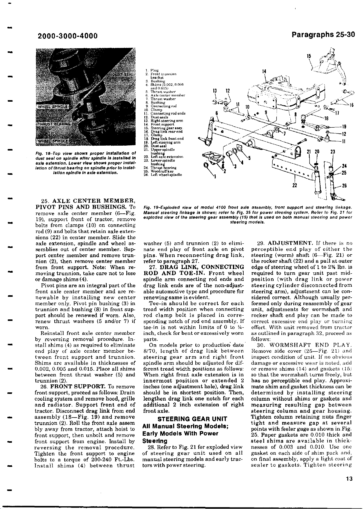
Fig. 17-Exploded view
rod
seals can be
screw (
8) in slot of rear sector gear (13)
(gear with double teeth
of thickness
clearance between head of adjusting
screw and slot in sector shaft. Shims
are available in thicknesses of 0.063,
0.064,0.066 and 0
sembled sector gear and adjusting
screw in gear housing so that teeth of
sector gear and ball nut are meshed as
shown in Fig.13. Install a new
(6-Fig. 12)
the "0"
ring and pull side cover onto
sector gear with adjusting
of power steering cylinder used on 2100
renewed but
will give zero to 0.002
that
on side cover
cylinder,
) with
a shim (7)
.
069. Insert the as-
(
4), lubricate
screw. In-
piston and piston rod
cylinder assembly.
stall the side cover retaining cap
screws and tighten them to a torque of
25 Ft.-Lbs. Turn adjusting
until there is no perceptible end play of
sector shaft, then install new packing
ring
Hold the adjusting screw in proper po-
sition while installing and tightening
lock nut.
sector shaft
0" ring
"
shaft as previously outlined for rear
sector shaft using Fig. 13 as a guide for
timing
teeth.
Fig. 16
nut is properly positioned as
explained In
to slot
,
2110,3100 and
are not serviced
(
3), washer
(
2) and lock nut (1).
Select a shim
9), then install front sector
(
front
sector to rear sector shaft
Install steering arms and
-
When valve retaining
text; stake
In
shaft as
shown.
1. Cylinderaesembly
2. Tubing seats (2)
3. Grease fitting
4. Dust seal
5. Inner seal
6. Outer seal
7. scraper washer
8. Bushing
9. Sn7, ring
10. Enssembly
models.
Piston
4110
except as a complete
screw in
(
7) for the front
tighten retaining nuts to a torque of
115-125 Ft.-Lbs. Reinstall control
valve as outlined in paragraph 21,
steering column as in
and reinstall
the steering
trol valve assembly
graph 17.
nut
23. POWER CYLINDERS. Power
cylinders are right and left assemblies
and should be identified prior to removal. Place a drain pan under cylinder to be removed and disconnect the
hydraulic
lines.
front and rear ball
and bump from mounting holes. Clear
cylinder of oil by moving piston rod
back and forth.
Loosen clamp and unscrew forward
end assembly (10-Fig. 17) from piston
rod. Remove
snap ring
to end of travel. Then, remove the
scraper washer
(7), wiperseal (6), alu-
minum bushing (8) and inner
(If seal did
not come
rod, remove with awl or other sharp
pointed tool.)
If cylinder or piston
the complete power cylinder must be
renewed as only the rod end assembly
and seal kit are available for service.
Reassemble by reversing disassembly
procedure. Seals should be soaked in
power steering fluid prior to installation. Carefully
install inner
piston rod with lip of seal inward, then,
using a dull pointed tool, work outer lip
of seal into proper position in cylinder.
Install the
aluminum
seal with lip outward, washer with
scraper lip outward and then install
retaining
assembly.
snap ring and
Reinstall
with ports upward, reconnect cylinder
lines and fill and bleed the system as
outlined in
paragraph
ward end assembly
far enough
onto piston rod so that
piston will reach end
front wheel spindles contact their
. Piston rod should not flex when
stops
cylinder is fully extended.
FORD
paragraph 19
gear and con-
as outlined in para-
Remove nuts from
socket assemblies
(9) and pull rod
seal (5).
out with piston
rod is damaged,
seal over
bushing, outer
forward end
power cylinder
10. Note: For-
should be screwed
of stroke before
FRONT SYSTEM AND STEERING
FRONT AXLE
STEERING LINKAGE
All Models
24. SPINDLE BUSHINGS. To
renew the spindle bushings (21 and 23
-Fig. 19), support front of tractor and
12
ASSEMBLY AND
(MODEL 4100 ALL PURPOSE)
disconnect steering arms (13 and 19)
from wheel spindles (26). Slide the
wheel and spindle assemblies (remove
wheels from hubs if desired for clearance) out of the front axle
(22). Drive old bushings from front axle
extensions and install new bushings
extensions
with piloted drift or bushing driver.
New bushings are final sized and
should not require reaming
installed
worn or rough
rect installation
. Renew thrust bearing (24) if
. Refer to Fig. 18 for cor-
of thrust bearing and
spindle dust seal.
if carefully
Page 13
-
2000
Fig. 18
dust seal on
axle extension
lation
3000-4000
Top view
-
of thrust
lation spindle In axle
proper installation of
shows
spindle is Installed in
after
spindle
Lower
view
.
bearingonspindle prior
shows
extension.
proper instal-
to instal-
1. Plug
2. Front trunnion
bracket
3. Bushing
4. Shim. (0.002, 0 006
and 0.015)
5. 'throat washer
6. Axle center member
7. Thrust washer
S. Bushing
9. Connecting rod
0. Clamp
1
11. Connecting rod end.
12. Dust ..Is
13. Right steering arm
14. Front support
15, Steering gear assy.
16. Drag link rear end
17. Clamp
1a Drag link front end
19. Left steering arm
20. Dust seal
21. Upper spindle
bushing
22. Left axle extension
23. Lower spindle
bushing
24. Thrust bearing
25. Woodruttkey
26. Left wheel spindle
Paragraphs 25-30
25. AXLE CENTER
MEMBER,
PIVOT PINS AND BUSHINGS. To
remove axle center member (6-Fig.
19), support front of tractor, remove
bolts from clamps (10) on connecting
rod (9) and bolts that retain axle exten-
sions
(22) in center member. Slide the
axle extension
semblies
port center member and
(2), then remove
nion
,
spindle and
out of center member. Sup-
remove trun-
center member
from front support. Note: When removing trunnion, take
care
or damage shims (4).
Pivot pins
are an integral
front axle center member and are renewable by installing new center
member only. Pivot pin bushing (3) in
trunnion and bushing (8) in front support should be renewed if worn, Also,
renew thrust washers (5 and/or 7) if
worn.
Reinstall front axle center member
by reversing removal procedure. Install shims (4) as required to eliminate
end play of axle center member between front support and trunnion.
Shims are available in thicknesses of
0.002, 0.005 and 0.015. Place all shims
between front thrust washer (5) and
trunnion (2).
26, FRONT SUPPORT. To remove
front support, proceed as follows: Drain
cooling system and remove hood,
and radiator. Support front end of
tractor. Disconnect
assembly (18-Fig.
trunnion (2). Roll the front
drag link from end
19) and remove
axle assem
bly away from tractor, attach hoist to
front support, then unbolt and remove
front support from engine. Install by
reversing the removal procedure.
Tighten the front support to engine
bolts to a torque of 200-240 Ft.-Lbs.
Install shims (4) between thrust
wheel as-
not to lose
part of the
grille
Fig. 19-Exploded view of model
Manual steering linkage is
exploded view
of the steering gear
shown
4100
;
refer
washer (5) and trunnion (2) to eliminate end play of front axle on pivot
pins. When reconnecting drag link,
refer to paragraph 27.
27. DRAG LINK, CONNECTING
ROD AND TOE-IN. Front wheel
spindle arm connecting rod ends and
drag link ends are of the non-adjustable automotive type and procedure for
renewing same is evident.
Toe-in should be correct for each
tread width position when connecting
rod clamp bolt is placed in corresponding notch of rod end assembly. If
toe-in is not within limits of 0 to '/4inch, check for bent or excessively worn
parts.
On models prior to production date
8/70, length of drag link between
steering gear arm and right front
spindle arm should be adjusted for different tread width positions as follows:
When right front axle extension is in
innermost position or extended 2
inches (one adjustment hole), drag link
should be in shortest position. Then,
lengthen drag link one notch for each
additional 2 inch extension of right
front axle.
STEERING GEAR UNIT
All Manual Steering Models;
Early Models With Power
Steering
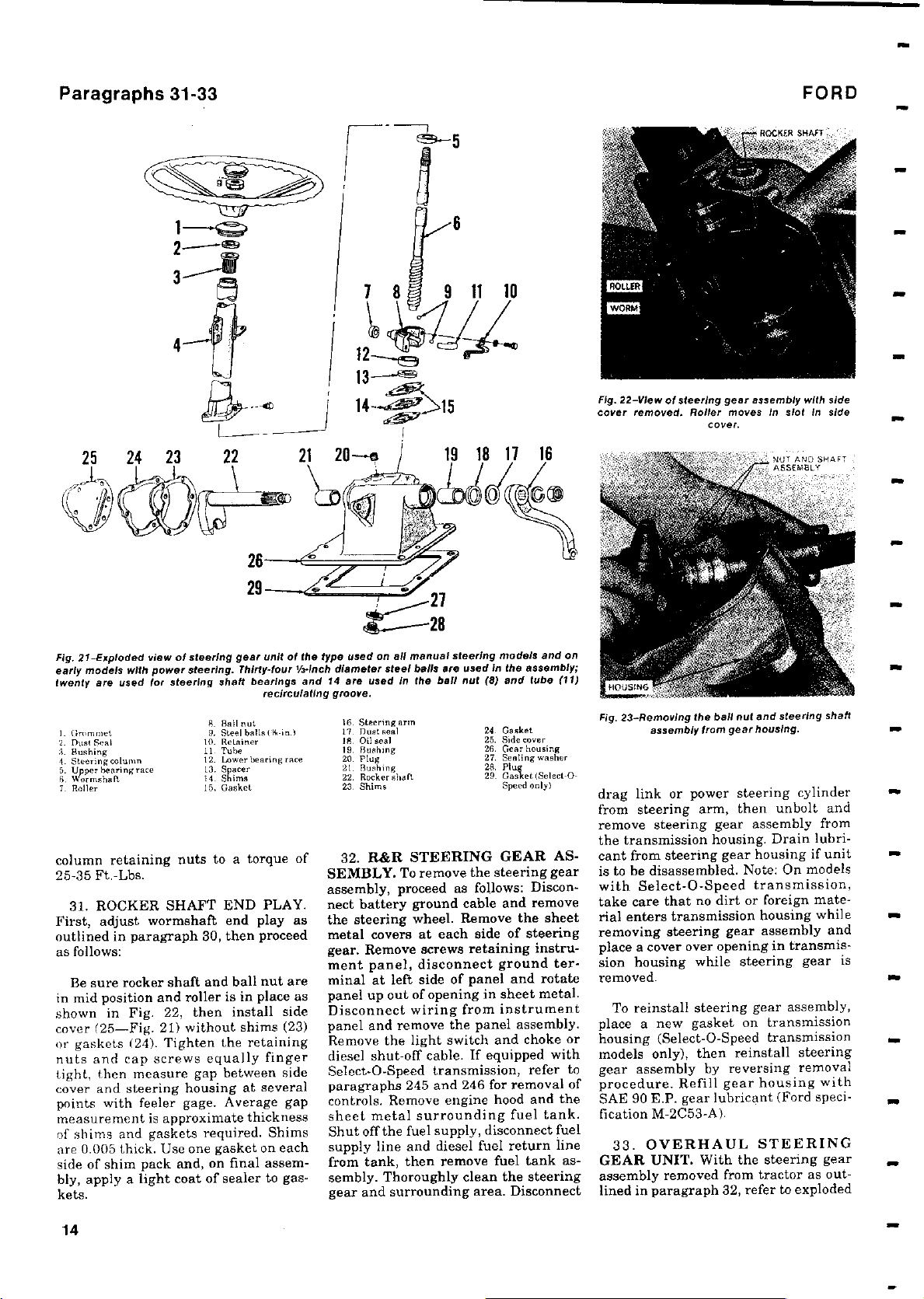
28. Refer to Fig. 21 for exploded view
of steering gear unit used on all
manual steering models and early tractors with power steering.
front axle assembly
to
Fig
assembly
steering
,
35 for
.
15) that is
(
models.
front support and
power
steering
used on both manual steering
system.Refer to Fig. 21 for
29. ADJUSTMENT. If there is no
perceptible end play of either the
steering (worm) shaft (6-Fig. 21) or
the rocker shaft (22) and a pull at outer
edge of steering wheel of 1 to 2% lbs. is
required to turn gear unit past midposition (with drag link or power
steering cylinder disconnected from
steering arm), adjustment can be considered correct. Although usually performed only during reassembly of gear
unit, adjustments for wormshaft and
rocker shaft end play can be made to
correct excessive end play or turning
effort. With unit removed from tractor
as outlined in paragraph 32, proceed as
follows:
30. WORMSHAFT END PLAY.
Remove side cover (25-Fig. 21) and
inspect condition of unit. If no obvious
damage or excessive wear is noted, add
or remove shims (14) and gaskets (15)
so that the wormshaft turns freely, but
has no perceptible end play. Approximate shim and gasket thickness can be
determined by installing steering
column without shims or gaskets and
measuring
resulting gap between
steering column and
Tighten column retaining nuts finger
tight and
measure gap
points with feeler gage as shown in Fig.
25. Paper gaskets are 0.010 thick and
steel shims are available in thicknesses of 0.003 and 0.010. Use one
gasket on each side of shim pack and,
on final assembly, apply a light coat of
sealer to gaskets. Tighten steering
steering linkage.
and power
gear housing.
at several
13
Page 14
Paragraphs 31-33
3 9
FORD
25 24 23 22
-
Exploded view of steering gear
Fig. 21
early models
twenty
are used
I- Ore mmet
2 Dust Seal
Pushing
3
.
4 Steering column
per hearing race
U
.
p
5
6. RormsheR
7 Roller
column retaining nuts to a torque of
25-35 Ft.-Lbs.
31. ROCKER SHAFT END PLAY.
First, adjust
outlined in paragraph 30, then proceed
as follows:
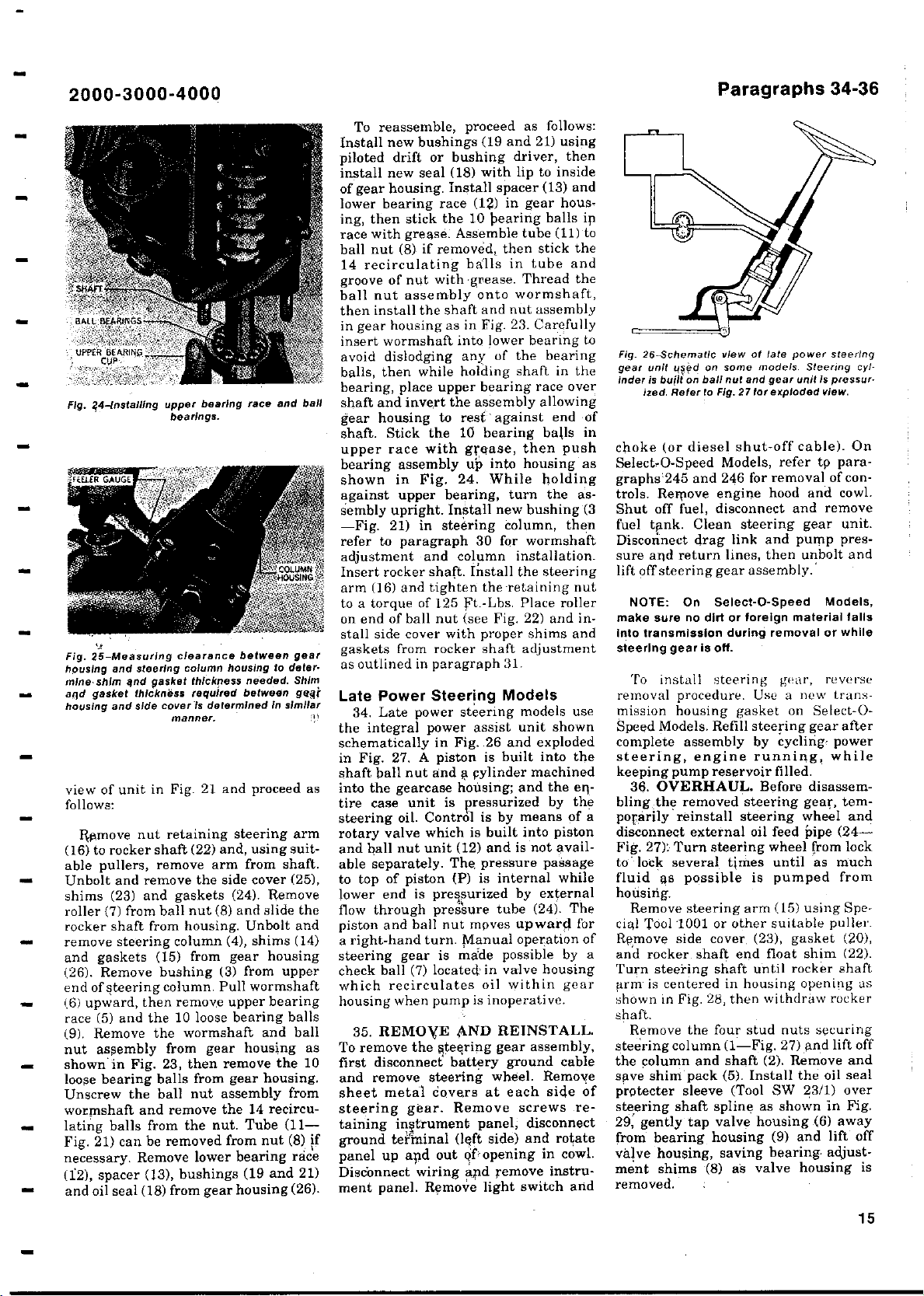
Be sure rocker shaft and ball nut are
in mid position and roller is in place as
shown in Fig. 22, then install side
cover (25-Fig. 21) without shims (23)
or gaskets (24). Tighten the retaining
nuts and cap screws equally finger
tight, then measure gap between side
cover and steering housing at several
points with feeler gage. Average gap
measurement is approximate thickness
of shims and gaskets required. Shims
are 0.005 thick. Use one gasket on each
side of shim pack and, on final assem-
bly, apply a light coat of sealer to gas-
kets.
power steering
with
for steering shaft bearings and 14
.
Thirty
8 Ball nut
9. Steel balls (*-inl
10
Retainer
.
11. Tube
12. Lower bearing race
13. Spacer
14. Shims
15. Gasket
wormahaft end play as
unit of the
four Vrinch diameter steel balls
-
recirculating groove.
type used on all manual
are used In
IS. Steering arm
Past seal
17.
Is.
Oil Real
19.
Flushing
20.
Plug
21.
Bushing
22.
Rocker shaft
23.
Shims
32. R&R STEERING
SEMBLY. To remove the
assembly, proceed as follows: Disconnect battery ground cable and remove
the steering wheel.
metal covers
Remove screws retaining
.
gear
ment panel
minal at left side of panel and rotate
panel up out of opening in sheet metal.
Disconnect wiring from instrument
panel and remove the panel assembly.
Remove the light switch and choke or
diesel shut-off cable. If equipped with
Select-O-Speed transmission, refer to
paragraphs 245 and 246 for removal of
controls. Remove engine hood and the
sheet metal surrounding fuel tank.
Shut off the fuel supply, disconnect fuel
supply line and diesel fuel return line
from tank, then remove fuel tank assembly. Thoroughly clean the steering
and surrounding
gear
19 18 11 16
steering
are used in
ball nut(8) and tube (11)
the
at each side
, disconnect ground ter-
models and on
24- Gasket
25. Side cover
Gear housing
.
26
27.
Sealing washer
28.
Plug
29-
Gasket (Select-O-
Speed only)
GEAR AS-
steering gear
Remove
area.
the assembly;
of steering
Disconnect
the sheet
instru-
Fig. 22-View
cover removed
Removing
Fig. 23-
assembly from gear housing.
of steering
.
Roller
the ball
gear assembly with
moves in slot In side
cover.
nut and steering
drag link or power steering cylinder
from steering arm, then unbolt and
remove steering gear assembly from
the transmission housing. Drain lubricant from steering gear housing if unit
is to be disassembled. Note: On models
with Select-O-Speed transmission,
take care that no dirt or foreign mate-
rial enters transmission housing while
removing steering gear assembly and
place a cover over opening in transmission housing while steering gear is
removed.
To reinstall steering gear assembly,
place a new gasket on transmission
housing (Select-O-Speed transmission
models only), then reinstall steering
gear assembly by reversing removal
procedure. Refill gear housing with
SAE 90 E.P. gear lubricant (Ford speci-
fication M-2C53-A).
33. OVERHAUL STEERING
GEAR UNIT
. With
the steering gear
assembly removed from tractor as outlined in paragraph 32, refer to exploded
side
shaft
14
Page 15
2000
Fig. ?,4-Installing upper bearing
Fig. 25
housing
mine shim and
aqd gasket thickness
housing
3000-4000
-
bearings.
Measuring
-
and
steering
asket
g
and side cover is
manner.
clearance
column housing
thickness
required
between
determined
race
needed.
between gggj
view of unit in Fig. 21 and proceed as
follows:
Ramove nut retaining steering arm
(16) to rocker shaft (22) and, using suitable pullers, remove arm from shaft.
Unbolt and remove the side cover (25),
shims (23) and gaskets (24). Remove
roller (7) from ball nut (8) and slide the
rocker shaft from housing. Unbolt and
remove steering column (4), shims (14)
and gaskets (15) from gear housing
(26). Remove bushing (3) from upper
end of steering column. Pull wormshaft
(6) upward, then remove upper bearing
race (5) and the 10 loose bearing balls
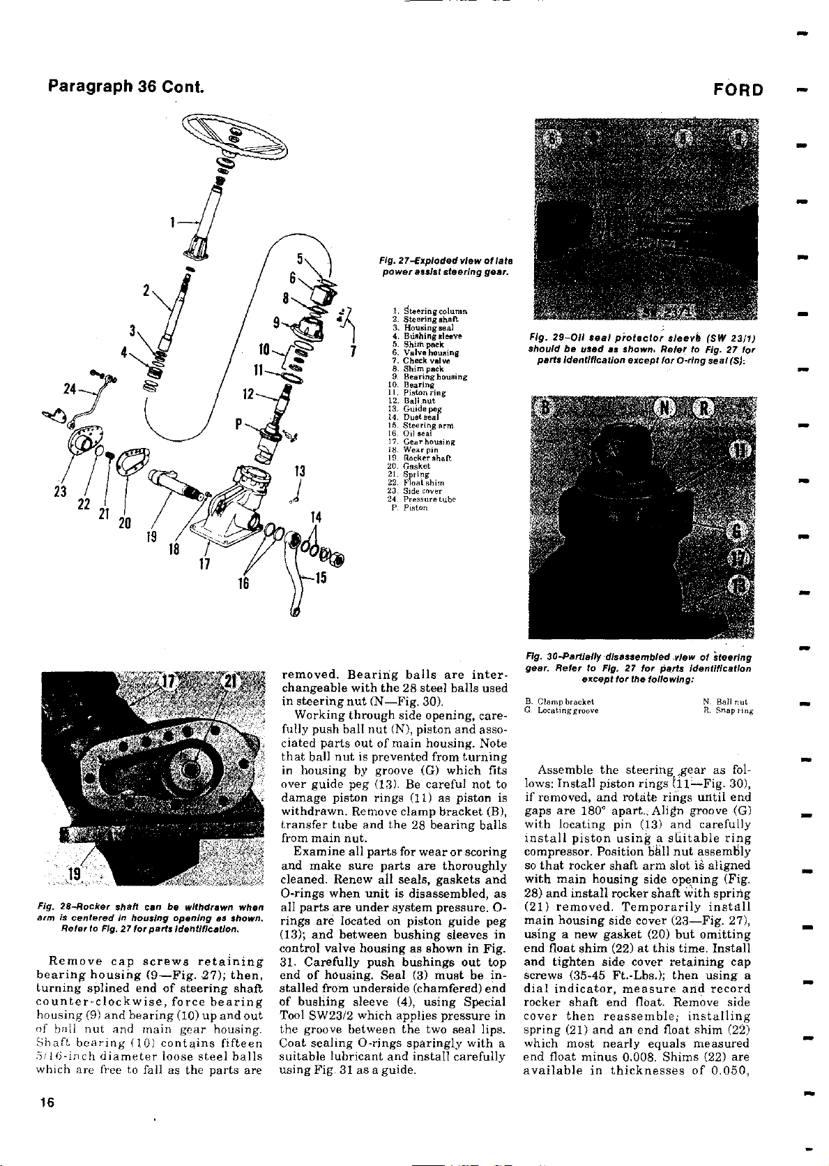
(9). Remove the wormshaft and ball
nut assembly from gear housing as
shown*in Fig. 23, then remove the 10
loose bearing balls from gear housing.
Unscrew the ball nut assembly from
wormshaft and remove the 14 recirculating balls from the nut. Tube (11Fig. 21) can be removed from nut (8) if
necessary. Remove lower bearing race
(12), spacer (13), bushings (19 and 21)
and oil seal (18) from gear housing (26).
and ball
gear
to deter-
Shim
in
similar
To reassemble, proceed as follows:
Install new bushings (19 and 21) using
piloted drift or bushing driver, then
install new seal (18) with lip to inside
of gear housing. install spacer (13) and
lower bearing race (12) in gear housing, then stick the 10 bearing balls in
race with grease. Assemble tube (11) to
ball nut (8) if removed, then stick the
14 recirculating balls in tube and
groove of nut with grease. Thread the
ball nut assembly onto wormshaft,
then install the shaft and nut assembly
in gear housing as in Fig. 23. Carefully
insert wormshaft into lower bearing to
avoid dislodging any of the bearing
balls, then while holding shaft in the
bearing, place upper bearing race over
shaft and invert the assembly allowing
gear housing to rest against end of
shaft. Stick the 10 bearing balls in
upper race with grease, then push
bearing assembly up into housing as
shown in Fig. 24. While holding
against upper bearing, turn the as-
sembly upright. Install new bushing (3
-Fig. 21) in steering column, then
refer to paragraph 30 for wormshaft
adjustment and column installation.
Insert rocker shaft. Install the steering
arm (a6) and tighten theretaining nut
to a torque of 125 Ft.-Lbs. Place roller
on end of ball nut (see Fig. 22) and in-
stall side cover with proper shims and
gaskets from rocker shaft adjustment
as outlined in paragraph 31.
Late Power Steering Models
34. Late power steering models use
the integral power assist unit shown
schematically in Fig. 26 and exploded
in Fig. 27. A piston is built into the
shaft ball nut and a pylinder machined
into the gearcase housing; and the eqtire case unit is pressurized by the
steering oil. Control is by means of a
rotary valve which is built into piston
and ball nut unit (12) and is not available separately. The, pressure passage
to top of piston (P) is internal while
lower end is pressurized by external
flow through pressure tube (24). The
piston and ball nut moves upward for
a right-hand turn. Manual operation of
steering gear is made possible by a
check ball (7) located: in valve housing
which recirculates oil within gear
housing when pump is inoperative.
35. REMOVE AND REINSTALL.
To remove the Steering gear assembly,
first disconnect battery ground cable
and remove steering wheel. Remove
sheet metal covers at each side of
steering gear. Remove screws retaining inf
ground teAninal (left side) and rotate
panel up apd out ofopening in cowl.
Disconnect wiring and remove instru-
ment panel. Remove light switch and
ftrument panel, disconnect
Paragraphs 34-36
Fig.
26-Schematic
gear unit
inder is
used on some
built on
ized.Refer
choke (or diesel shut-off cable). On
Select-O-Speed Models, refer tp paragraphs`245 and 246 for removal of controls. Remove engine hood and cowl.
Shut off fuel, disconnect and remove
fuel tank. Clean steering gear unit.
Disconnect drag link and pump pressure and return lines, then unbolt and
lift off steering gear assembly.
NOTE: On Select-O-Speed Models,
make sure
Into transmission during removal
steering gear is off.
To install steering gear, reverse
removal procedure. Use a new transmission housing gasket on Select-OSpeed Models. Refill steering gear after
complete assembly by cycling- power
steering
keeping pump reservoir filled.
36. OVERHAUL. Before
blingthe removed steering gear, temporarily reinstall steering wheel and
disconnect external oil
Fig. 27): Turn
to _. lock
several
fluid as
housing.
Remove steering arm (15) using Special Tool -1001 or other suitable puller.
Remove side cover. (23), gasket (20),
and rocker shaft end float shim (22).
Turn steering shaft until rocker shaft
arm is centered in housing opening as
shown in Fig. 28, then withdraw rocker
shaft.
Remove the four stud nuts securing
steering column (1-Fig. 27) and lift off
the column and shaft (2). Remove and
save shim pack (5). Install the oil seal
protecter sleeve (Tool SW 23/1) over
steering
shaft spline as shown in Fig.
29, gently tap valve housing (6)
from bearing housing (9) and lift off
valve housing, saving bearing-adjust-
ment shims
removed.
viewoflate power steering
models.
ball nut and
to Fig.27
no dirt or foreign
gear
for exploded view.
, engine running, while
feed pipe (24-
steering
wheel from lock
times until as much
possible is
pumped from
(8) as valve
unit is pressur.
material falls
housing is
Steering
or while
disassem-
away
cyl-
15
Page 16
Paragraph
36 Cont.
FORD
Fig. 28
-
Rocker
arm is centered in housing opening as shown.
Refer
shaft can
to
Fig
.
27 for parts identification.
be withdrawn when
Remove cap screws retaining
bearing housing
(
9-Fig
. 2
7); then,
turning splined end of steering shaft
counter-clockwise
housing(9) and bearing
of ball nut and
Shaft bearing (
5'I6-inch diameter
,
force bearing
(
10) up and out
main gear housing.
10) contains fifteen
loose steel balls
which are free to fall as the parts are
Fig. 27-Exploded
power
assist steering
1. !iteeringcolumn
2. Steering shaft
3. Housing seal
4. Bushing above
5. Shish peck
6. Valve housing
7. Check valve
6. Shim pack
9. Bear., housing
10. Bearing
I I. Piston ring
12. Bali at
13. Guide peg
t4. nustseal
I5. Steering arm
16. Oil seal
17. over housing
Is. Wear pin
19. Backer shaft
20. Gasket
21. Spring
22. Float shim
23. Side cover
24. Pressure tube
P. Piston
removed
changeable
in steering
.
Bearing balls are inter-
with the
28 steel balls used
nut (N-Fig. 30).
Working through side opening, care-
fully push ball nut (N), piston and associated parts out of main housing. Note
that ball nut is prevented from turning
in housing by groove (G) which fits
over guide peg (13). Be careful not to
damage piston rings
(
11) as piston is
withdrawn. Remove clamp bracket (B),
transfer tube and the 28 bearing balls
from
main nut.
Examine all parts
and make sure parts are
cleaned
.
Renew all seals
0-rings when unit
for wear
thoroughly
,
gaskets and
is disassembled, as
all parts are under system pressure. 0-
rings are
(13); and between
control valve
31. Carefully
end of housing
stalled from underside
of bushing
located
on piston guide peg
bushing sleeves in
housing as shown in Fig.
push bushings out top
.
Seal (3
must be in-
)
(chamfered) end
sleeve(4), using Special
Tool SW23/2 which applies pressure in
the groove between the two seal lips.
Coat sealing 0-rings sparingly with a
suitable lubricant and install carefully
using Fig. 31 as a guide.
view of late
gear.
or scoring
Fig.
29
-
011
should be used as shown.Refe
parts
Fig. 30
gear.Refer to Fig
B. Clamp bracket
aLocatinggroove
seal protector
identification except
-
Partially disassembled view of steering
except
.
27 for
for the following:
sleeve
r
for 0-ring seal (S):
parts
Assemble the steering gear as follows: Install piston rings hl-Fig. 30),
if removed, and rotate rings until end
gaps are 180° apart.; Align groove (G)
with locating pin (13) and carefully
install piston using a suitable ring
compressor. Position bhll nut assembly
so that rocker shaft arm slot is aligned
with main housing side opening (Fig.
28) and install rocker shaft with spring
(21) removed. Temporarily install
main housing side cover (23-Fig. 27),
using a new gasket (20) but omitting
end float shim (22) at this time. Install
and tighten side cover retaining cap
screws (35-45 Ft.-Lbs.); then using a
dial indicator, measure and record
rocker shaft end float. Remove side
cover then reassemble; installing
spring (21) and an end float shim (22)
which most nearly equals measured
end float minus 0.008. Shims (22) are
available in thicknesses of 0.050,
(
SW 2311)
to Fig. 27 for
identification
N. Ball nut
R. Snap ring
16
Page 17
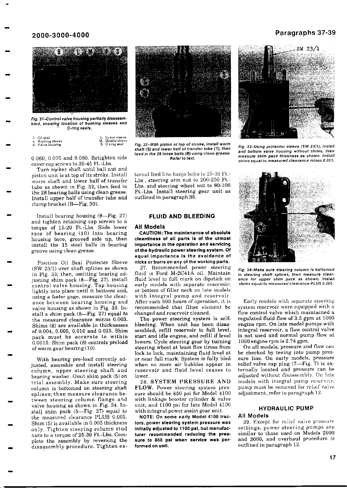
2000
3000-4000
-
Paragraphs 37-39
Fig.
31-Control
bled, showing
3 Oil seal L. Lowersleove
4. Bushing sleeve M. Middle sleeve
6. valve housing S. 0-ring seal
valve housing partially
location of bushing
0-ring seals.
0.060, 0.070 and 0.080. Retighten side
cover cap screws to 35-45 Ft.-Lbs.
Turn rocker shaft until ball nut and
piston unit is at top of its stroke. Install
worm shaft and lower half of transfer
tube as shown in Fig. 32, then feed in
the 28 bearing
balls using clean grease.
Install upper half of transfer tube and
clamp bracket (B-Fig. 30).
Install bearing housing (9-Fig. 27)
and tighten retaining cap screws to a
torque of 15-20 Ft.-Lbs. Slide lower
race of bearing (10) into bearing
housing bore, grooved side up, then
install the 15 steel balls in bearing
groove using clean grease.
Position Oil Seal Protecter Sleeve
(SW 23/1) over shaft splines as shown
in Fig. 33; then, omitting bearing ad-
justing shim pack (8-Fig. 27), install
control valve housing. Tap housing
lightly into place until it bottoms and,
using a feeler gage, measure the clearance between bearing housing and
valve housing as shown in Fig. 33. Install a shim pack (8-Fig. 27) equal to
the measured clearance minus 0.003.
Shims (8) are available in thicknesses
of 0.004, 0.005, 0.010 and 0.025. Shim
pack must be accurate to within
0.0015. Shim pack (8) controls preload
of worm gear bearing (10).
With bearing pre-load correctly ad-
justed, assemble and install steering
column, upper steering shaft and
bearing washer. Omit shim pack (5) on
trial assembly. Make sure steering
column is bottomed on steering shaft
splines; then measure clearance between steering column flange and
valve housing as shown in Fig. 34. Install shim pack (5-Fig 27) equal to
the measured clearance PLUS 0.005.
Shim (5) is available in 0.005 thickness
only. Tighten steering column stud
nuts to a torque of 25-30 Ft.-Lbs. Complete the assembly by reversing the
disassembly procedure. Tighten ex-
disassem-
sleeves
and
32-With piston at top of
Fig.
(S) and lower halt
shaft
feed inthe 28 loose
Refer
stroke, install worm
of transfer tube (r), then
) using
balls
(B
to text.
ternal feed line banjo bolts to 25-30 Ft.-
Lbs., steering arm nut to 200-250 Ft.Lbs. and
Ft.-Lbs.
outlined
steering
Install steering gear unit as
in paragraph 35.
FLUID AND
wheel nut to 80-100
BLEEDING
All Models
CAUTION:
cleanliness of all parts Is of the utmost
Importance In the operation and servicing
of the hydraulic power steering system. Of
equal Importance Is the avoidance of
nicks or burrs on any of the working parts.
37. Recommended power steering
fluid is Ford M-2C41A oil, Maintain
fluid level to full mark on dipstick on
early models with separate reservoir;
or bottom of filler neck on late models
with integral pump and reservoir.
After each 600 hours of operation, it is
recommended that filter element be
changed and reservoir cleaned.
The power steering system is selfbleeding. When unit has been disassembled, refill reservoir to full level,
start and idle engine, and refill if level
lowers. Cycle steering gear by turning
steering wheel at least five times from
lock to lock, maintaining fluid level at
or near full mark. System is fully bled
when no more air bubbles appear in
reservoir and fluid level ceases to
lower.
38. SYSTEM PRESSURE AND
FLOW. Power steering system pressure should be 850 psi for Model 4100
with linkage booster cylinder & valve
unit; and 1100 psi for late Model 4100
with integral power assist gear unit.
NOTE
tors
,
initially adjusted to 1100 psi, but manufacturer recommended reducing the pressure to 850 psi when service was performed on unit.
The maintenance of absolute
On some early Model 4100 trac-
:
power steering system pressure was
clean
grease.
Fig. 33-Using protector
and bottom
measure
shims
Fig.
in
steering shaft splines
ance
shims equal to measured clearance
valve
pack thickness as shown
shim
equal to measured clearance
34-
Make
sure steering column
for upper
sleeve(SW 23
housing without
,
shim
pack
then measure clear-
as shown.Install
1), install
/
shims;
then
.
Install
minus 0.003.
is
bottomed
0.005.
PLUS
Early models with separate steering
system reservoir were equipped with a
flow control valve which maintained a
regulated fluid flow of 3.5 gpm at 1000
engine rpm. On late model pumps with
integral reservoir, a flow control valve
is not used and normal pump flow at
1000 engine rpm is 2.74 gpm.
On all models, pressure and flow can
be checked by teeing into pump pressure line. On early models, pressure
relief valve cap plug (7-Fig. 7) is externally located and pressure can be
adjusted without disassembly. On late
models with integral pump reservoir,
pump must be removed for relief valve
adjustment, refer to paragraph 12.
HYDRAULIC PUMP
All Models
39. Except for relief valve pressure
settings, power steering pumps are
similar to those used on Models 2000
and 3000, and overhaul procedure is
outlined in paragraph 12.
17
Page 18
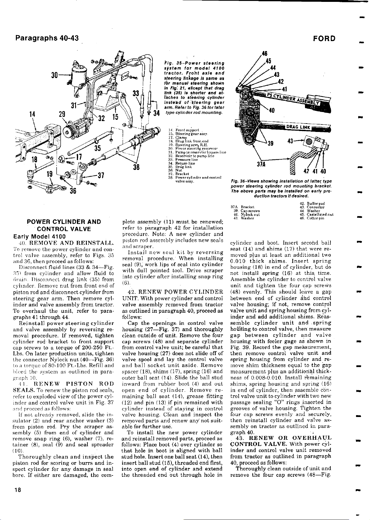
Paragraphs 40-43
POWER CYLINDER AND
CONTROL VALVE
Early Model 4100
40. REMOVE AND REINSTALL.
To remove the power cylinder and controt valve assembly, refer to Figs. 35
and 36, then proceed as follows:
Disconnect fluid lines (33 & 34 Fig.
.45) from cylinder and allow fluid to
drain. Disconnect drag link (35) from
cylinder. Remove nut from front end of
piston rod and disconnect cylinder from
steering gear arm. Then remove cylinder and valve assembly from tractor.
To overhaul the unit, refer to paragraphs 41 through 44.
Reinstall power
and valve assembly by reversing removal procedure. If removed, tighten
cylinder rod bracket to front support
cap screws to a torque of 200-250 Ft.Lbs. On later production units, tighten
the connector Nylock nut (40-Fig. 36)
to a torque of 80-100 Ft.-Lbs. Refill and
bleed the system as outlined in paragraph 10.
I I. RENEW PISTON ROD
SEALS. To renew the piston rod seals,
refer to exploded view of the power cylinder and control valve unit in Fig. 37
and proceed as follows:
If not already removed, slide the in-
sulator (2) and rear anchor washer (3)
from piston rod. Pry the scraper assembly (5) from end of cylinder and
remove snap ring (6), washer (7), retainer (8), seal (9) and seal spreader
(10).
Thoroughly clean and inspect the
piston rod for scoring or burrs and inspect cylinder for any
bore. If either
steering
damage in seal
are damaged
, the earn-
cylinder
Pig. 35
-Power
system
tractor
steering linkage
fbr manual,
In Fig'
link (35)
tachesto steering
instead of s
arm.
type cylinder rod mounting.
for
model
.
Froht
steering
21,
except that
Is shorter and
Refer to
4 Front support
15. Steering gear asey
7. Clamp
19. Steering
s6. Power steering reservoir
31. Pump In reservoir hypos l'.
32. Reservoir to pump line
33. Pressure line
34. Return line
35. Dreg link
36. Nut
37. Bracket
38. Powercylinder and control
teering gear
Fig. 36 for later
Diag link frontend
armi Rn.
valve assy.
plete assembly (11) must. be renewed;
refer to paragraph 42 for installation
procedure. Note: A new cylinder and
piston rod assembly includes new seals
and scraper.
Install new seal kit by reversing
removal procedure. When installing
seal (9), work lips of seal into cylinder
with dull pointed tool. Drive scraper
into cylinder after installing snap ring
(6).
42. RENEW POWER CYLINDER
UNIT. With power cylinder and control
valve assembly removed from tractor
as outlined in paragraph 40, proceed as
follows:
Cap the openings in control valve
housing (27-Fig. 37) and thoroughly
clean outside of unit. Remove the four
cap screws (48) and separate cylinder
from control valve unit; be careful that
valve housing (27) does not slide off of
valve spool and lay the control valve
and ball socket unit aside. Remove
spacer (18), shims (17), spring (16) and
outer ball seat (14). Slide the ball stud
inward from rubber boot (4) and out
open end of cylinder. Remove remaining ball seat (14), grease fitting
(12) and pin (13) if pin remained with
cylinder instead of staying in control
valve housing. Clean and inspect the
removed parts and renew any not suitable for further use.
To install the new power cylinder
and reinstall removed parts, proceed as
follows: Place boot (4) over cylinder so
that hole in boot is aligned with ball
stud hole. Insert one ball seat (14), then
insert ball stud (15), threaded end first,
into open end of cylinder and extend
the threaded end out through hole in
steering
4100
axleand
is same as
shown
drag
cylinder
at-
Fig. 36-Views showing Installation
power steering cylinder rod
The
above
37A. Bracket
39. cap 'crews
Nyybock net
40
,
41. We her
parts may
duction tractors if desired.
be installed on
cylinder and boot. Insert second ball
seat (14) and shims (17) that were re-
moved plus at least an additional two
0.010 thick shims. Insert spring
housing (18) in end of cylinder, but do
not install spring (16) at this, time.
Assemble the cylinder to control valve
unit and tighten the four cap screws
(48) evenly. This should leave a gap
between end of cylinder dhd control
valve housing; if not, remove control
valve unit and spring housing from cylinder and add additional shims. Reas-
semble cylinder unit and spring
h iRing to control valve, then measure
gap between cylinder and valve
housing with feeler gage as shown in
Fig. 39. Record the gap measurement,
then remove control valve unit and
spring housing from cylinder and remove shim thickness equal to the gap
measurement plus an additiorihl thickness of 0.008-0.010. Install remaining
shims, spring housing and spring (16)
in end of cylinder, then assemble control valve unit to cylinder with two new
passage sealing "0" rings inserted in
grooves of valve housing. tighten the
four cap screws evenly and securely,
then reinstall cylinder and valve as-
sembly on tractor as outlined in paragraph 40.
43. RENEW OR OVERHAUL
CONTROL VALVE. With power cyl-
inder and control valve unit removed
from tractor as outlined in paragraph
40, proceed as follows:
Thoroughly clean outside of unit and
remove the four cap screws (48-Fig.
FORD
latter
o
f
mounting bracket.
early pro-
42. Buffer pad
43. Connector
44. Washer
45. Castellated nut
46. Cotter pin
type
18
Page 19
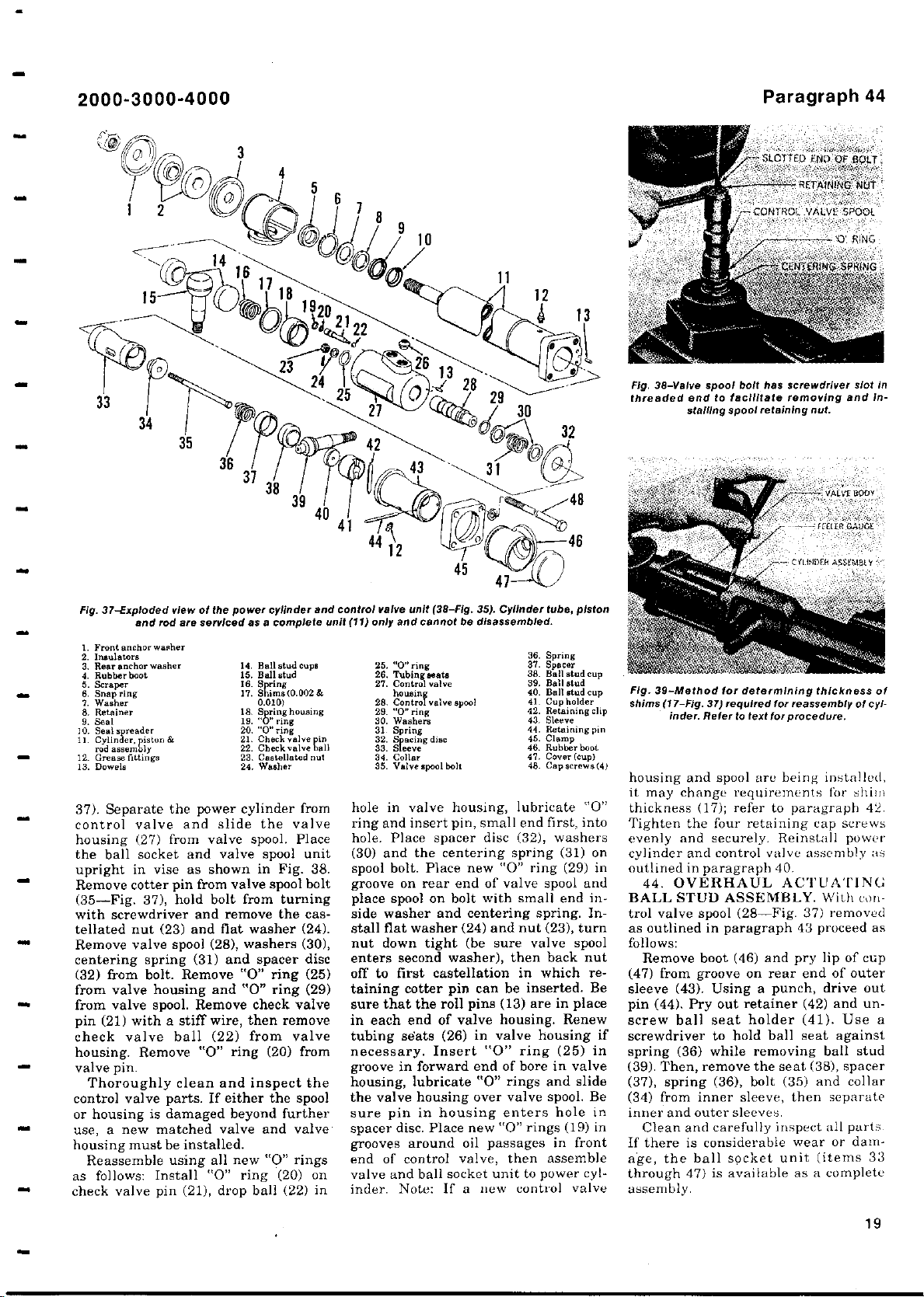
2000
3000-4000
-
46
Fig. 38
-
spool
Valve
threaded end to facilitate
stalling
bolt has screwdriver
spool retaining nut.
Paragraph 44
LOTTED END OF BOLT!
RETAINING NUT `
ROC VALVE SPOOL
'0' RING
1NG
slot
removing and in-
In
Fig. 37-Exploded view
1. Front anchor washer
2. Insulators
3. Rear anchor washer
4. Rubber boot
5. Scraper
6. Snap ring
7. Washer
8. Retainer
9. Seal
I0. Seal spreader
11
.
12. Grease fittings
13. Dowels
and rod
Cylinder
rod assebly
ston&
,
of the
are
power cylinder and
serviced as a complete
14. Bell stud cup.
15. Ball stud
16. Spring
17. shim.(0.002&
0.010)
18Sp
19.
"o"
20.
"0" ring
Check valve pi
21.
22.
Check valve bell
23.
24.
37). Separate the power cylinder from
control valve and slide the valve
housing (27) from valve spool. Place
the ball socket and valve spool unit
upright in vise as shown in Fig. 38.
Remove cotter pin from valve spool bolt
(35-Fig. 37), hold bolt from turning
with screwdriver and remove the castellated nut (23) and flat washer (24).
Remove valve spool (28), washers (30),
centering spring (31) and spacer disc
(32) from bolt. Remove "0" ring (25)
from valve housing and "0" ring (29)
from valve spool. Remove check valve
pin (21) with a stiff wire, then remove
check valve ball (22) from valve
housing. Remove "0" ring (20) from
valve pin.
Thoroughly clean and inspect the
control valve parts. If either the spool
or housing is damaged beyond further
use, a new matched valve and valve
housing must be installed.
Reassemble using all new "O" rings
as follows: Install "0" ring (20) on
check valve pin (21), drop ball (22) in
ring housing
ring
Castellated out
Washer
unit
(38-Fig.
control valve
unit (11) only
25. "0" ring
26. Tubingseats
27. Control valve
28, Control valve spool
29. "0" ring
30. Washers
31 Spring
32. S acing disc
33. Sleeve
34. Collar
35. Valve spool bolt
and
housing
cannot be
35).
disassembled.
hole in valve housing, lubricate "0"
ring and insert pin, small end first, into
hole. Place spacer disc (32), washers
(30) and the centering spring (31) on
bolt. Place new "0" ring (29) in
spool
groove on rear end of valve spool and
place spool on bolt with small end inside washer and centering spring. Install flat washer (24) and nut (23), turn
nut down tight (be sure valve spool
enters second washer), then back nut
off to first
castellation
taining cotter pin can be inserted. Be
sure
that the roll
pins
in each end of valve housing. Renew
tubing
(26) in valve housing if
seats
necessary. Insert "0" ring (25) in
groove in forward end of bore in valve
housing, lubricate "0" rings and slide
the valve housing over valve spool. Be
sure pin in housing enters hole in
spacer disc. Place new "0" rings (19) in
grooves around oil passages in front
end of control valve, then assemble
valve and ball socket unit to power cylinder. Note: If a new control valve
Cylinder
tube,
36. Spring
37. Spacer
38. Ball stud cup
39. Bell stud
40. Ball stud cup
41. Cupholder
42. Retaining clip
43. Sleeve
44. Retaining in
45. Clamp
46. Rubber boot
47. Cover(cup)
48. Cap screws (4)
in which re-
(13) are in place
piston
Fig.
39-Method
shims
(17-Fig.
inder.Refer to text
housing and spool are being installed,
it may change requirements
thickness
Tighten the
evenly and securely. Reinstall power
cylinder and control valve assembly as
outlined in paragraph 40.
44. OVERHAUL
BALL STUD ASSEMBLY
trol valve spool
for determining
37) required for reassembly of cyl-
(
17); refer to paragraph 42.
four retaining cap screws
thicknessof
for procedure.
ACTUATING
. With con-
(
28-Fig. 37
)
as outlined in paragraph 43 proceed as
follows:
(
Remove boot
46) and pry lip of cup
(47) from groove on rear end of outer
sleeve
43). Using a punch
(
pin (44),Pry out retainer
screw ball seat holder
,
(
42) and un-
(
41). Use a
screwdriver to hold ball seat against
spring (36) while removing ball stud
(39). Then, remove the seat
(
(37), spring
36), bolt
(
38), spacer
(
35) and collar
(34) from inner sleeve, then separate
inner and outer sleeves,
Clean and carefully inspect all parts
If there is considerable wear or dam-
age, the ball socket unit
through 47)
is available as a complete
(items 33
assembly.
for shim
removed
drive out
19
Page 20
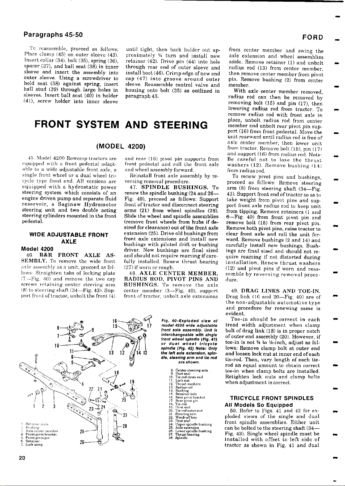
Paragraphs 45-50
FORD
To reassemble, proceed as follows:
Place clamp (45) on outer sleeve (43).
Insert collar (34), bolt (35), spring (36),
spacer (37), and ball seat (38) in inner
sleeve and insert the assembly into
outer sleeve. Using a screwdriver to
hold seat (38) against spring, insert
ball stud (39) through large holes in
sleeves. Insert ball seat (40) in holder
(41), screw holder into inner sleeve
FRONT SYSTEM
(MODEL 4200)
45. Model 4200 Rowcrop tractors are
equipped with a front pedestal adaptable to a wide adjustable front axle, a
single front wheel or a dual wheel tri-
cycle type front end. All versions are
equipped with a hydrostatic power
steering
engine driven pump and separate fluid
reservoir
steering unit
steering cylinders mounted in the front
pedestal.
Model 4200
46. R&R FRONT AXLE ASSEMBLY. To remove the wide front
axle assembly as a unit, proceed as fol-
lows: Straighten tabs of locking plate
(7-Fig. 40) and remove the two cap
screws retaining center steering arm
(8) to steering shaft (34-Fig. 43). Support front of tractor, unbolt the front (4)
arl.nner pn,te
❑
'.I F
5. nt pivot b
Fr
5.
F
7.
R
]. Lo
system which
,
a Saginaw
and two
consists of an
Hydramotor
double acting
WIDE ADJUSTABLE FRONT
AXLE
wiung
t pnVn ,
rumber
o n
r
pivot
kinerer
er
k strip
pin
acket
ront
etain
c
until tight, then back holder out approximately 5 turn and install new
retainer (42). Drive pin (44) into hole
through rear end of outer sleeve and
install boot (46). Crimp edge of new end
cap (47) into groove around outer
sleeve. Reassemble control valve and
housing onto bolt (35) as outlined in
paragraph 43.
AND STEERING
and rear (16) pivot pin supports from
front pedestal and roll the front axle
and wheel assembly forward.
Reinstall front axle assembly by re-
versing removal procedure.
47. SPINDLE BUSHINGS. To
renew the spindle bushing (24 and 26Fig. 40), proceed as follows: Support
front of tractor and disconnect steering
arms (21) from wheel spindles (28).
Slide the wheel and spindle
(remove front wheels from hubs if desired for clearance) out of the front axle
extension (25). Drive old bushings from
front axle extensions and install new
bushings with piloted drift or bushing
driver. New bushings are final sized
and should not require reaming if carefully installed. Renew thrust bearing
(27) if worn or rough.
48. AXLE CENTER MEMBER,
RADIUS ROD, PIVOT PINS AND
BUSHINGS. To remove the axle
center member (3-Fig. 40), support
front of tractor, unbolt axle extensions
Fig. 40-Exploded view of
model
4200
front axle assembly. Unit Is
interchangeable with single
front wheel spindle (Fig. 41)
or dual wheel tricycle
spindle (Fig.
the left
dle, steering
8. Center steering arm
9. Dust seal
16. Tie red inner and
it. Lock nut
12. Thrust washers
13. Radios rod
14. Bushing
15. Retainer bolt
l6. hear pivot bracket
17. Roar pivot pin
8. Tic rod
In. oustseoi
20. Tie rod enter end
21 Steeringarm
22. waodrufTkey
23. Dust seal
24. Up er spindle bushing
25. Axle extension
26. Low er spindle bushing
27. Thrust bearing
28. Spindle
assemblies
wide adjustable
42) Note:
axle
extension, spin-
arm
are shown.
Only
and tie rod
from center member and swing the
axle extension and wheel assemblies
aside. Remove retainer (1) and unbolt
radius rod (13) from center member,
then remove center member from pivot
pin. Remove bushing (2) from center
member.
With axle center member removed,
radius rod can then be removed by
removing bolt (15) and pin (17), then
lowering radius rod from tractor. To
remove radius rod with front axle in
place, unbolt radius rod from center
member and unbolt rear pivot pin support (16) from front pedestal. Move the
unit rearward until radius rod is free of
axle center member, then lower unit
from tractor. Remove bolt (15), pin (17)
and support (16) from radius rod. Note:
Be careful not to lose the thrust
washers (12). Remove bushing (14)
from radius rod.
To renew pivot pins and bushings,
proceed as follows: Remove steering
arm (8) from steering shaft (34-Fig.
43). Support front end of tractor so as to
take weight from pivot pins and support front axle radius rod to keep unit
from tipping. Remove retainers (1 and
6-Fig. 40) from front pivot pin and
remove bolt (15) from rear pivot pin.
Remove both pivot pins, raise tractor to
clear front axle and roll the unit forward. Remove bushings (2 and 14) and
carefully install new bushings. Bushings are final sized and should not require reaming if not distorted during
installation. Renew thrust washers
(12) and pivot pins if worn and reassemble by reversing removal procedure.
49. DRAG LINKS AND TOE-IN.
Drag link (10 and 20-Fig. 40) are of
the non-adjustable automotive type
and procedure for renewing same is
evident.
Toe-in should be correct in each
tread width adjustment when clamp
bolt of drag link (18) is in proper notch
of outer end assembly (20). However, if
toe-in is not V4 to t/z-inch, adjust as fol-
lows: Remove clamp bolt at outer end
and loosen lock nut at inner end of each
tie-rod. Then, vary length of each tierod an equal amount to obtain correct
toe-in when clamp bolts are installed.
Retighten lock nuts and clamp bolts
when adjustment is correct.
TRICYCLE FRONT SPINDLES
All Models So Equipped
50. Refer to Figs. 41 and 42 for exploded views of the single and dual
front spindle assemblies. Either unit
can be bolted to the steering shaft (34Fig. 43). Single wheel spindle must be
installed with offset to left side of
tractor as shown in Fig. 41 and dual
20
Page 21
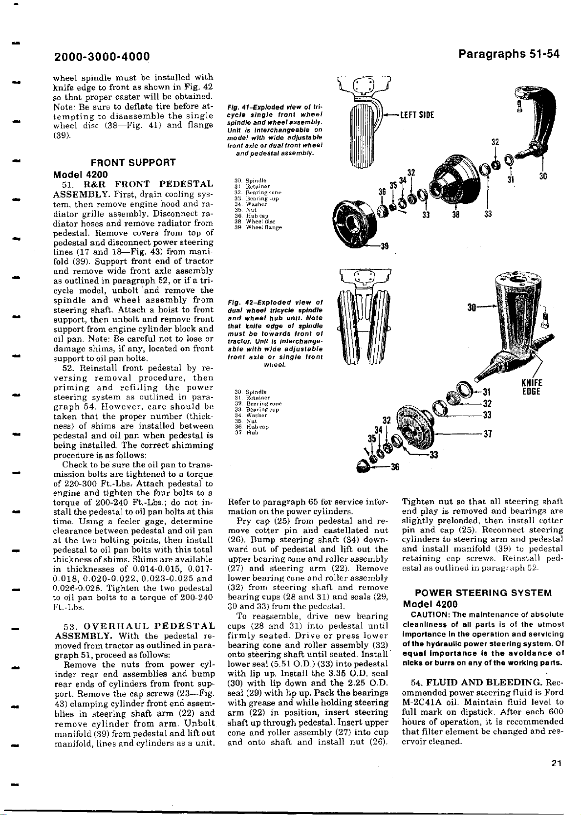
2000
3000-4000
-
Paragraphs 51-54
wheel spindle must be installed with
as shown in Fig. 42
knife edge to
front
so that proper caster will be obtained.
Note: Be sure to deflate tire before attempting to disassemble the single
wheel disc (38-Fig. 41) and flange
(39).
FRONT SUPPORT
Model 4200
51. R&R FRONT PEDESTAL
ASSEMBLY. First, drain cooling system, then remove engine hood and radiator grille assembly. Disconnect radiator hoses and remove radiator from
pedestal. Remove covers from top of
pedestal and disconnect power steering
(17 and 18-Fig. 43) from mani-
lines
fold (39). Support front end of tractor
and remove wide front
as outlined in paragraph 52, or if a tri-
cycle model, unbolt and remove the
spindle and wheel assembly from
steering shaft. Attach a hoist to front
support, then unbolt and remove front
support from engine cylinder block and
oil pan. Note: Be careful not to lose or
damage shims, if any, located on front
support to oil pan bolts.
52. Reinstall front pedestal by reversing removal procedure, then
priming and refilling the power
steering system as outlined in paragraph 54. However, care should be
taken that the proper number (thick-
ness) of shims are installed between
pedestal and oil pan when pedestal is
being installed. The correct shimming
procedure is as follows:
Check to be sure the oil pan to transmission bolts are tightened to a torque
of 220-300 Ft.-Lbs. Attach pedestal to
engine
and tighten the four bolts to a
torque of 200-240 Ft.-Lbs.; do not install the pedestal to oil pan bolts at this
time. Using a feeler gage, determine
clearance between pedestal and oil pan
at the two bolting points, then install
pedestal to oil pan bolts with this total
thickness of shims. Shims are available
in thicknesses of 0.014-0.015, 0.017-
0.018, 0.020-0.022, 0,023-0.025 and
0.026-0.028. Tighten the two pedestal
to oil pan bolts to a torque of 200-240
Ft.-Lbs.
53. OVERHAUL PEDESTAL
ASSEMBLY. With the pedestal removed from tractor as outlined in paragraph 51, proceed as follows:
Remove the nuts from power cyl-
inder rear end assemblies and bump
rear ends of cylinders from front sup-
port. Remove the cap screws (23-Fig.
43) clamping cylinder front end assemblies in steering shaft arm (22) and
remove cylinder from arm. Unbolt
manifold (39) from pedestal and lift out
manifold, lines and cylinders as a unit.
axle
assembly
-
Exploded view of tri-
Fig. 41
cycle
spindle and wheel
Unit is Interchangeable on
model
front axle
and pedestal
30. spindle
31 Retainer
32. Bearing mne
33. Hearing cup
34. Wauler
35. Nut
36. Hub cap
38 Wheel disc
39. Wheel Range
Fig. 42-Exploded view of
wheel tricycle spindle
dual
and
wheel hub unit. Note
that knife edge of spindle
must be
tractor.Unit is
able with wide adjustable
front axle
30. Spindle
31. Retainer
32. Bearmgcone
33. 13euring cup
34. Washer
35. Nut
36. Hubcap
37. Huh
front wheel
single
wide
with
or dual
assembly.
towards front of
interchange.
or single front
wheel.
assembly.
j
ustable
ad
front wheel
Refer to paragraph 65 for service information on the power cylinders.
Pry cap (25) from pedestal and re-
move cotter pin and castellated nut
(26). Bump steering shaft (34) downward out of pedestal and lift out the
upper bearing cone and roller assembly
(27) and steering arm (22). Remove
lower bearing cone and roller assembly
(32) from steering shaft and remove
bearing cups (28 and 31) and seals (29,
30 and 33) from the pedestal.
To reassemble, drive new bearing
cups (28 and 31) into pedestal until
firmly seated. Drive or press lower
bearing cone and roller assembly (32)
onto steering shaft until seated. Install
lower seal (5.51 O.D.) (33) into pedestal
with lip up. Install the 3.35 O.D. seal
(30) with lip down and the 2.25 O.D.
seal (29) with lip up. Pack the bearings
with grease and while holding steering
arm (22) in position, insert steering
shaft up through pedestal. Insert upper
cone and roller assembly (27) into cup
and onto shaft and install nut (26).
Tighten nut so that all steering shaft
end play is removed and bearings are
slightly preloaded, then install cotter
pin and cap (25). Reconnect steering
cylinders to steering arm and pedestal
and install manifold (39) to pedestal
retaining cap screws- Reinstall pedestal as outlined in paragraph 52.
POWER STEERING SYSTEM
Model 4200
CAUTION: The maintenance
cleanliness of all parts
importance in the operation and servicing
of the hydraulic power steering system. Of
equal Importance is the avoidance of
nicks or burrs on any of the working parts.
54. FLUID AND BLEEDING. Recommended power steering fluid is Ford
M-2C41A oil. Maintain fluid level to
full mark on dipstick. After each 600
hours of operation, it is recommended
that filter element be changed and reservoir cleaned.
of absolute
is of the utmost
21
Page 22
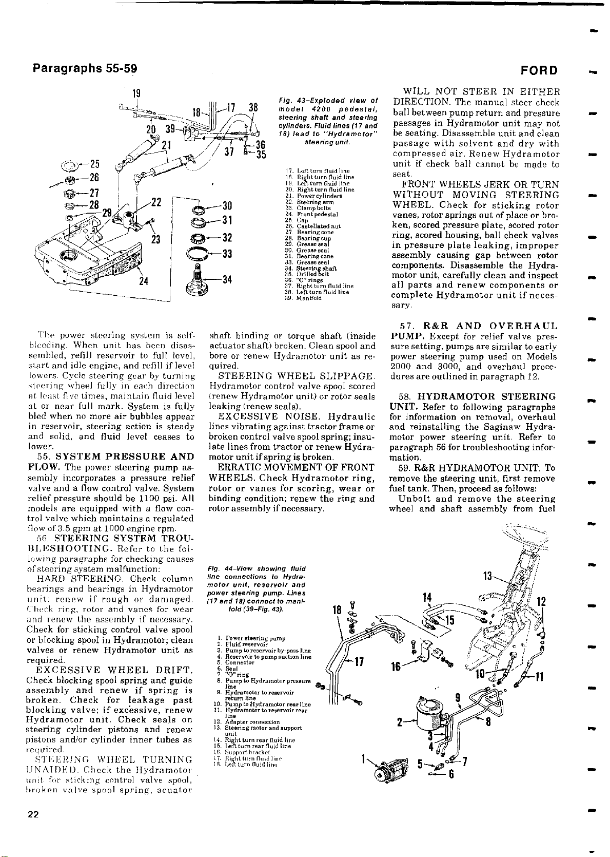
Paragraphs 55-59
FORD
The power steering system is self-
bleeding
.
When unit has been disassembled, refill reservoir to full level,
start and idle engine
,
and refill if level
lowers. Cycle steering gear by turning
steering
al least five times
at or near full mark
wheel fully in each direction
,
maintain fluid level
.
System is fully
bled when no more air bubbles appear
in reservoir
,
steering action is steady
and solid, and fluid level ceases to
lower.
55. SYSTEM PRESSURE AND
FLOW
.
The power steering pump assembly incorporates a pressure relief
valve and a flow control valve. System
relief pressure should be 1100 psi. All
models are equipped with a flow con-
trol valve which maintains a regulated
flow of 3.5 gpm at 1000 engine rpm.
56. STEERING SYSTEM TROU-
BLESHOOTING
.
Refer to the fol-
lowing paragraphs for checking causes
of steering system malfunction:
HARD STEERING
.
Check column
hearings and bearings in Hydramotor
unit; renew if rough or damaged.
Check ring,
rotor and vanes for wear
and renew the assembly if necessary.
Check for sticking control valve spool
or blocking spool in Hydramotor; clean
valves or renew Hydramotor unit as
required.
EXCESSIVE WHEEL DRIFT.
Check blocking spool spring and guide
assembly and renew if spring is
broken.Check for leakage past
blocking valve
;
if excessive, renew
Hydramotor unit. Check seals on
steering cylinder pistons and renew
pistons and/or cylinder inner tubes as
required.
STEERING WHEEL TURNING
UNAIDED.
Check the Hydramotor
unit for sticking control valve spool,
broken valve spool spring
,
acuator
Fig. 43-
Exploded view of
model
steering
cylinders.
18) lead to
4200
shaft
Fluid lines (17 and
"
Hydramotor"
Steering
17. Left turn nuid line
IS. R, lit turn fluid line
19. Left turn need line
20. Right turn fluid line
21 Power 1,haden.
22. Steering arm
23. Clamp bolt,
24. Front pedestal
26. Cap
26. Castellated nut
27. Bearing cone
28. Bearingcuy
29. Grease sea
30. Grease seal
31. Bearing cone
33. Grease seal
34. Steering shaft
35. Drilled bolt
36. "0e rings
37. Right turn fluid line
38. Left turnnuid line
39. Manifold
l
shaft binding or torque shaft (inside
actuator shaft) broken. Clean spool and
bore or renew Hydramotor unit as required.
STEERING WHEEL SLIPPAGE.
Hydramotor control valve spool scored
(renew Hydramotor unit) or rotor seals
leaking (renew seals).
EXCESSIVE NOISE. Hydraulic
lines vibrating against tractor frame or
broken control valve spool spring; insulate lines from tractor or renew Hydramotor unit if spring is broken.
ERRATIC MOVEMENT OF FRONT
WHEELS. Check Hydramotor ring,
rotor or vanes for scoring, wear or
binding condition; renew the ring and
rotor assembly if necessary.
Fig. 44-View showing fluid
line connections
motor unit, reservoir and
power
steering
(17 and 18)connect to
fold (39-Fig.
L Power steering pump
2. Fluid reservoir
3. Pump to reservoir by-pass line
4. Reservoir to pump suction line
5. Connector
6. Seal
7. "0" ring
8. Pump to Hydrometer pressure
e
lin
9. Hydramotor to reservoir
return line
10. Pu me to Hydramotor rear I ins
11. Hydramotor to reservoirrear
him
12. Adapter connection
13, steering motor and support
unit
i 4. Right turn
5. Izn turn rear fluid Ime
16. Support hrarket
17_ lieght turn nand
ls. lIn. turn nand hne
to
Hydra-
pump.
mani-
43).
rear nuid line
Lines
pedestal,
and steering
unit.
WILL NOT STEER IN EITHER
DIRECTION. The manual steer check
ball between pump return and pressure
passages
in Hydramotor unit may not
be seating. Disassemble unit and clean
passage with solvent and dry with
compressed air. Renew Hydramotor
unit if check ball cannot be made to
seat.
FRONT WHEELS JERK OR TURN
WITHOUT MOVING STEERING
WHEEL. Check for sticking rotor
vanes, rotor
ken, scored
ring, scored housing,
in pressure plate leaking
springs out
pressure
of place or bro-
plate, scored rotor
ball check valves
, improper
assembly causing gap between rotor
components.Disassemble
motor unit, carefully clean
all parts and
renew components or
the Hydra-
and inspect
complete Hydramotor unit if necessary.
57. R&R AND OVERHAUL
PUMP. Except for relief valve pressure setting, pumps are similar to early
power steering pump used on Models
2000 and 3000, and overhaul procedures are outlined in paragraph 12.
58. HYDRAMOTOR STEERING
UNIT. Refer to following paragraphs
for information on removal, overhaul
and reinstalling the Saginaw Hydramotor power steering unit. Refer to
paragraph 56 for troubleshooting information.
59. R&R HYDRAMOTOR UNIT. To
remove the steering unit, first remove
fuel tank. Then, proceed as follows:
Unbolt and remove the steering
wheel and shaft assembly from fuel
22
Page 23
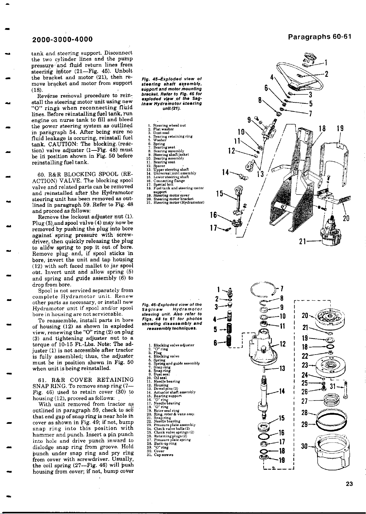
2000
3000-4000
-
tank and steering support. Disconnect
the two cylinder lines and the pump
pressure: and fluid return lines from
steering motor (21-Fig. 45). Unbolt
the bracket and motor (21), then remove bracket and motor from support
(18).
Reverse removal procedure to rein-
stall the steering motor unit
"0" rings when reconnecting fluid
Before reinstalling
lines.
fuel tank, run
engine on nurse tank to fill and bleed
the power steering system as outlined
in paragraph 54. After being sure no
fluid leakage is occuring, reinstall fuel
tank. CAUTION: The blocking, (reaction) valve adjuster (1-Fig. 48) must
be irl position shown in Fig. 50 before
reinstalling fuel tank.
60. R&R BLOCKING SPOOL (REACTION) VALVE. The blocking spool
valve and related parts can be removed
and reinstalled after the Hydramotor
steering unit has been removed as outlined in paragraph 59. Refer to Fig. 48
and proceed as follows:
Remove the lockout adjuster nut (1).
Plug (3),and spool valve (4) may new be
removed by pushing the plug into bore
against spring pressure with `screw-
driver t then quickly releasing the plug
to alldw spring to pop it out of bore.
Remove plug- and, if Spool sticks in
bore, invert the unit and tap housing
(12) with soft faced mallet to jar spool
out. Invert unit and allow spring (5)
and spring and guide assembly (6) to
drop from bore.
Spool is not serviced separately from
complete Hydramotor unit. Renew
other parts as necessary, or install new
Hydramotor unit if spool and/or spool
bore in housing are not serviceable.
To reassemble, install parts in bore
of housing (12) as shown in exploded
view, renewing the "O" ring (2) on plug
(3) and tightening adjuster nut to a
torque of 10-15 Ft.-Lbs. Note: The ad-
juster (1) is not accessible after tractor
is fully assembled; thus, the adjuster
must be in position shown in Fig. 50
when unit is being reinstalled.
61. R&R COVER RETAINING
SNAP RING. To remove snap ring (7Fig. 46) used to retain cover (30) to
housing (12), proceed as follows:
With unit removed from tractor as
outlined in paragraph 59, check to set
that end gap of snap ring is near hole ih
cover as shown in Fig. 49; if not, bump
snap ring into this position with
hammer and punch. Insert a pin punch
into hole and drive punch inward to
dislodge snap ring from groove. Hold
punch under snap ring and pry ring
from cover with screwdriver. Usually,
the coil spring (27-Fig. 46) will push
housing from cover; if not, bump cover
using new
Fig. 45-Exploded view of
steering
support and
bracket.
exploded
inaw Hydremotor
1. Steering wheel nut
2. Flat washer
3. Dust .eel
4. Bearing retaining ring
5 Washer
6. Spring
7. Beeringeeat
e. Bearing assembly
9. Steering eh.ftjacktt
10. Bearing assembly
11. Bearing seat
12. s
p
arer
13. Upper steering shaft
14. Universal joint assembly
15, luwerateeringshaft
16. Connecting flange
17. Special bolt
18. Fuel tank and steering motor
support
19. steering motor cover
20. Steering motor bracket
21. Steering motor
Fig. 46-Exploded
Saginaw Hydramotor
steering unit
48 to 61
Figs.
Showing disassembly and
reassembly
1. Blocking valve adjuster
2. 0"ring
3. Plug
4. Blocking valve
5. Spring
6. Spring and guide assembly
7. Snap ring
8. Snapring
9. Dual seas
10. Oil said
11. Needle bearing
12. Housing
13. Dowel pine (2)
14. Actuator shaft assembly
15. Bearing support
16. 0" rin
17. Needle bearing
18. "0" ring
19. Rotoraealdng
20. Ring, rotor & vane easy.
21. Snap ring
22. Needle bearing
23. Pressure plate assembly
24. Check valve ball. (2)
25. Check valve springs (2)
26. Retaining
27. Pressure pl to spring
28. Back-up ring
30. Cover
31. capecrewa
shaft
motor mounting
Refer to
view ,of
unit (21).
.
Also refer
for photos
techniques.
lugs (2)
p
assembly,
Fig.
the Sag-
steering
Hydramotor)
(
view of the
Paragraphs 60-61
46 for
r-------1
to
25 31--^
14 26 A
27
28
I 29
30
23
Page 24
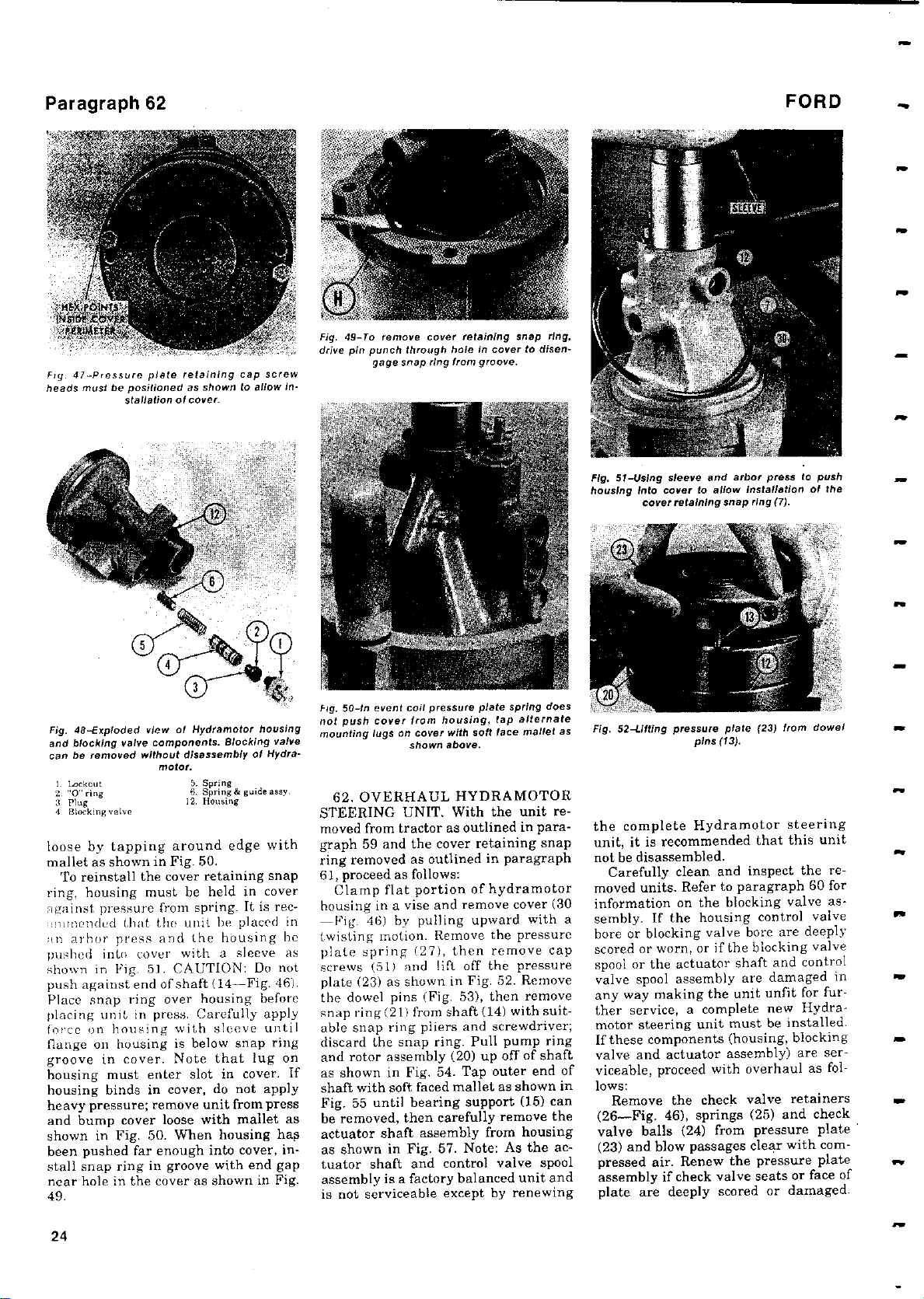
Paragraph 62
FORD
47-Pressure
Fig.
heads must
Fig. 40-Exploded view of Hydramotor
and blocking
can be removed
I Lockout
3 Plug - 12.
4 Blocking valve
plate retaining
be positioned as shown
stallation of cover.
components
valve
without disassembly
motor.
5. Spring
6. Spring & guide assy.
cap screw
to
Blocking valve
.
Housing
allow in-
housing
of Hydra-
loose by tapping around edge with
mallet as shown in Fig. 50.
To reinstall the cover retaining snap
ring, housing must be held in cover
against pressure
:Innl:ended that the unit be placed in
nn arbor press and the housing he
pushed into cover with
shown in Fig. 5]. CAUTION: Do not
push against end of shaft
Place snap ring over housing before
placing unit in press. Carefully apply
force on housing with sleeve until
flange on housing is below snap ring
groove in cover. Note that lug on
housing must enter slot in cover. If
housing binds in cover, do not apply
heavy pressure
and bump cover loose with mallet as
shown in Fig. 50. When housing has
been pushed far enough into cover, in-
stall snap ring in groove with end gap
near hole in the cover as shown in Fig.
49.
from spring. It is rec-
a sleeve as
(14-Fig. 46).
remove unit from press
;
To remove cover retaining
Fig.49-
drive pin punch
Fig.
50-In event
not push
mounting lugs
snap ring from
gage
cover from housing
on cover with soft
hole
through
pressure
coil
shown above.
in cover
groove.
plate spring
lap alternate
,
face
62. OVERHAUL HYDRAMOTOR
STEERING UNIT. With the unit removed from tractor as outlined in paragraph 59 and the cover retaining snap
ring removed as outlined in paragraph
61, proceed as follows:
Clamp flat portion of hydramotor
housing in a vise and remove cover (30
-Fig. 46) by pulling upward with a
twisting motion. Remove the pressure
plate spring (27), then remove cap
screws (51) and lift off the pressure
plate (23) as shown in Fig. 52. Remove
the dowel pins (Fig. 53), then remove
snap ring (21) from shaft (14) with suit-
able snap ring pliers and screwdriver;
discard the snap ring. Pull pump ring
and rotor assembly (20) up off of shaft
as shown in Fig. 54. Tap outer end of
shaft with soft faced mallet as shown in
Fig. 55 until bearing support (15) can
be removed, then carefully remove the
actuator shaft assembly from housing
as shown in Fig. 57. Note: As the actuator shaft and control valve spool
assembly is a factory balanced unit and
is not serviceable except by renewing
snap ring,
to
disen-
does
mallet as
Fig. 51-Using
housing
Into
cover retaining
Fig.
52-Lifting
sleeve and
cover
pressure
arbor press
allow installation
to
snap ring (7).
plate
pins (13).
(23) from
the complete Hydramotor steering
unit, it is recommended that this unit
not be disassembled.
Carefully clean and inspect the re-
moved units. Refer to paragraph 60 for
information on the blocking valve assembly. If the housing control valve
bore or blocking valve bore are deeply
scored or worn, or if the blocking valve
spool or the actuator shaft and control
valve spool assembly are damaged in
any
making the unit unfit for fur-
way
ther service, a complete new Hydra-
motor steering unit must be installed.
If these components (housing, blocking
valve and actuator assembly) are serviceable, proceed with overhaul as follows:
Remove the check valve retainers
(26-Fig. 46), springs (25) and check
valve balls (24) from pressure plate
(23) and blow passages clear with compressed air. Renew the pressure plate
assembly if check valve seats or face of
plate are deeply scored or damaged.
to
push
of the
dowel
M
w
24
Page 25
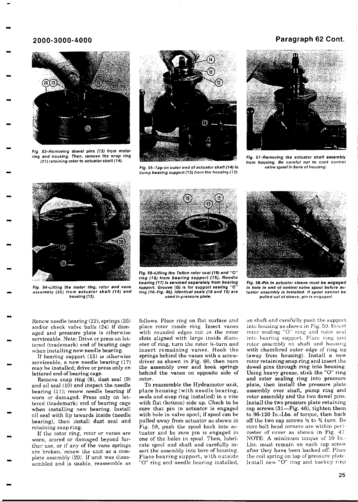
2000
Fig.
53-Removing
ring
and housing
(
21)retaining
3000-4000
-
dowel pins
.
Then
rotor to
remove
,
actuator
from motor
(13)
the snap
shaft(14).
ring
-
Tap on
Fig. 55
bump bearing
outer
support
actuator shaft (14) to
end of
(
15)
from
the housing (12).
Fig. 67-
Removing
from housing
valve
Paragraph
actuator shaft
the
Be careful
.
spoolln
not
bore
62 Cont.
to cock
of housing.
assembly
control
ring,
Fig. 54-Lilting
assembly
the motor
20) from actuator shaft
(
housing (12).
rotor
Renew needle bearing (22), springs (25)
and/or check valve balls (24) if damaged and pressure plate is otherwise
serviceable. Note: Drive or press on lettered (trademark) end of bearing cage
when installing new needle bearing.
If bearing support (15) is otherwise
serviceable, a new needle bearing (17)
may be installed; drive or press only on
lettered end of bearing cage.
Remove snap ring (8), dust seal (9)
and oil seal (10) and inspect the needle
bearing (11); renew needle bearing if
worn or damaged. Press only on lettered (trademark) end of bearing cage
when installing new bearing. Install
oil seal with lip towards inside (needle
bearing), then install dust seal and
retaining snap ring.
If the rotor ring, rotor or vanes are
worn, scored or damaged beyond further use, or if any of the vane springs
are broken, renew the unit as a complete assembly (20). If unit was disassembled and is usable, reassemble as
and
(
14)
Fig. 56
-
tilting the
from bearing support
)
(
17) is serviced
.
Groove
used
vane
and
ring (18
bearing
support
ring (16-Fig.46).
follows: Place ring on flat surface and
place rotor inside ring. Insert vanes
with rounded edges out in the rotor
slots aligned
eter of ring,
turn the rotor 1/4-turn and
insert remaining vanes.
springs behind the vanes
driver as shown
the assembly over and hook springs
behind the vanes on opposite side of
rotor.
To reassemble the Hydramotor unit,
place housing
seals and snap ring installed
with flat (bottom)
sure that
with
pin in actuator is engaged
hole in valve spool
pulled away from actuator as shown in
Fig. 58, push the spool back into actuator and be sure
one of the holes in spool. Then, lubri-
cate spool
and shaft and carefully insert the assembly into bore of housing.
Place bearing support, with outside
"0" ring and needle bearing installed,
(
19)
Teflon
rotor seal
separately
for support sealing "0"
(
G) is
Identical seals(18 and 19) are
in pressure plate.
and "G"
(
15). Needle
from bearing
with large inside diam-
Hook the
with
a screw-
in Fig. 60, then turn
(with needle
bearing,
) in a vise
side
up. Check to be
;
if spool can be
pin is engaged in
Fig. 58-Pin in actuator sleeve must be
In hole In end of control valve
tuator
assembly
pulled out
is Installed.If
of sleeve,pin is
spool
spool cannot be
engaged.
on shaft and carefully push the support
into housing as shown in Fig. 59. Insert
rotor sealing "O" ring and rotor seal
into bearing support. Place ring and
rotor assembly on shaft and housing
with chamfered
(away from housing
outer edge
).
of ring up
Install a new
rotor retaining snap ring and insert the
dowel pins through ring into housing.
stick the "0" ring
Using heavy grease
,
and rotor sealing ring into pressure
plate, then install the pressure plate
assembly over shaft, pump ring and
rotor assembly and the two dowel pins.
Install the two pressure plate retaining
.
cap screws
to 96-120 In
off the
two cap screws 1/2 to %
sure bolt head
meter
of cover as shown in Fig. 47.
(
31-Fig
Lbs. of torque,
:-
46), tighten them
then back
corners are within peri-
NOTE: A minimum torque of 10 In.Lbs. must remain on each cap screw
after
have been backed off. Place
they
the coil spring on top of pressure plate.
Install new "0" ring and backup ring
engaged
before
turn. Be
ac-
25
Page 26
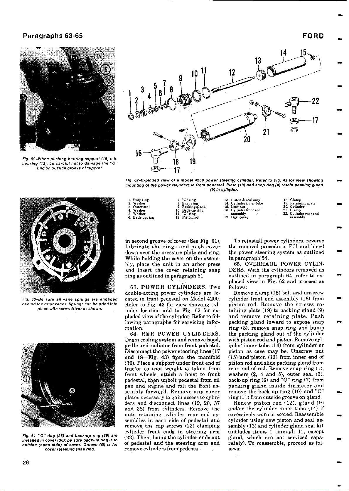
Paragraphs 63-65
9
10 11 1
FORD
13
2
22
EN---17
F
Fig. 59-When pushing bearing
housing
ring on
Fig.
60-Be sure
behind
the
place with screwdriver
Fig.61-"
installed in
outside(open side
careful not to damage the "O"
(
12), be
,
outside
groove of
all
rotor
0"
cover(30);besure back
cover
vane
vanes.
ring
(
29) and back
)ofcover.Groove
retaining
Springs
support(15) into
support.
springs
can be
as shown.
-upring
ring.
snap
are engaged
pried into
29)
(
-upring Is to
G) is for
(
16
18 19
x"-17
Fig. 62
Exploded
-
mounting of the power cylinders in front pedestal
1. Snap ring
2. Washer
3. Outer seal 9 I've 16. f.ock out 20. Cylinder
4. Washer 10. Back
5. Washer 11. "O"ring assembly 22. Cylinderreerend
6. Back-up ring 12. Piston rod 17. Oust cover assembly
in second
view of a model
groove of
cover(See Fig. 61),
lubricate the rings and push cover
down over the pressure plate and ring.
While holding the cover on
bly, place the unit in an arbor press
and insert the- cover retaining snap
ring as outlined in paragraph 61.
63. POWER CYLINDERS. Two
double-acting power cylinders are located in front pedestal on Model 4200.
Refer to Fig. 43 for view showing cylinder location and to Fig. 62 for exploded view of the cylinder. Refer to following paragraphs for servicing information.
64. R&R POWER CYLINDERS.
Drain cooling system and
grille and radiator
from front
Disconnect the power steering lines (17
and 18-Fig. 43). f;pm the manifold
(39). Place a support under front end of
tractor so that weight is taken from
front wheels, attach a hoist to front
pedestal, then unbolt pedestal from oil
pan and engine and roll the front assembly forward. Remove any cover
plates necessary to gain
ders and disconnect lines (19, 20, 37
and 38) from cylinders. Remove the
nuts retaining cylinder rear end assemblies in'each side of pedestal and
remove the cap screws (23) clamping
cylinder front ends
are
(22). Then, bump the cylinder ends out
of pedestal and the steering arm and
remove cylinders from pedestal.
4200
7. "0" ties
6. Snappring 14. Cylinder inner tube 19. Retaining plate
up ring 16. Cylinder front end 21. Clamp
-
the assem-
remove hood,
pedestal.
access
to cylin-
in steering arm
power
steering cylinder.Refer
.
Plate(19) and snap ring (B) retain
(9) in
cyllnder.
13. Piston & seat stay
the removal procedure. Fill and bleed
the power steering system as outlined
in paragraph 54.
DERS. With the cylinders removed as
outlined in paragraph 64, refer to exploded view in Fig. 62 and proceed as
follows:
cylinder front end assembly (16) from
piston rod. Remove the screws retaining plate (19) to packing gland (9)
and remove retaining plate. Push
packing gland inward to expose snap
ring (8), remove snap ring and bump
the packing gland out of the cylinder
with piston rod and piston. Remove cylinder inner tube (14) from cylinder or
piston as
(15)'and'piston (13) from inner end of
piston rod and slide packing gland from
rear end of rod. Remove snap ring (1),
washers
back-up ring (6) and "0" ring (7) from
packing gland inside diameter and
remove the back-up ring (10) and "0"
ring (11) from outside groove on gland.
and/or the cylinder inner tube (14) if
excessively worn or scored. Reassemble
cylinder using new piston and seal assembly (13) and cylinder gland seal kit
(includes items 1 through 11, except
gland, which are not serviced separately). To reassemble, proceed' as fol-
lows:
43
to Fig
.
for view showing
.
packing gland
18. Clamp
To reinstall power cylinders, reverse
65. OVERHAUL POWER CYLIN-
Remove clamp (18) bolt and unscrew
case may be. Unscrew nut
(2, 4 and 5), outer seal (3),
Renew piston rod (12), gland (9)
26
Page 27
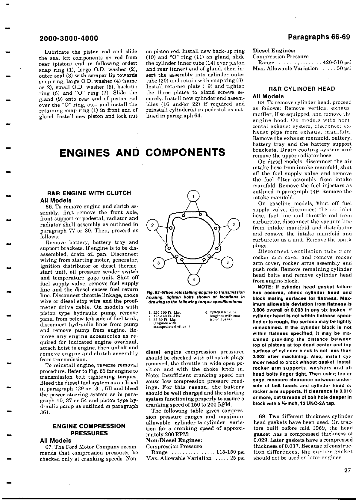
2000
3000-4000
-
Paragraphs 66-69
Lubricate the piston rod and slide
the seal kit components on rod from
rear
1), large O
snap ring
outer seal (3
snap ring
(
)
large O.D. washer
,
as 2), small O
6) and
ring
(
9) onto rear end of piston rod
(
gland
over
the "0"
retaining snap ring
Install new piston and lock nut
gland
.
ENGINES
with scraper lip towards
D. washer
.
0" ring
"
ring
D. washer (2),
.
(
(
5), back-up
7). Slide the
(
etc., and install the
,
1) in front end of
(
4) (same
AND COMPONENTS
end in following order:
)
(
piston
R&R ENGINE WITH CLUTCH
All Models
66. To remove engine and clutch assembly, first remove the front axle,
front support or pedestal, radiator and
radiator shell assembly as outlined in
paragraph 77 or 80. Then, proceed as
follows:
Remove battery, battery tray and
support brackets. If engine is to be disassembled, drain oil pan. Disconnect
wiring from starting motor, generator,
ignition distributor or diesel thermo-
start unit,
and temperature
oil pressure
gage unit
sender switch
. Shut off
fuel supply valve, remove fuel supply
line and the
line. Disconnect
diesel excess
throttle linkage, choke
fuel return
wire or diesel stop wire and the proofmeter drive cable. On models with
piston type hydraulic pump, remove
panel from below left side of fuel tank,
from pump
disconnect hydraulic
lines
and remove pump from engine. Remove any engine
accessories as re-
quired for indicated engine overhaul,
attach hoist to engine, then unbolt and
remove engine and clutch assembly
from transmission.
To reinstall engine, reverse removal
procedure. Refer to Fig. 63 for engine to
transmission bolt tightening torques.
Bleed the diesel fuel system as outlined
in paragraph 129 or 131, fill and bleed
the power steering
system as in para-
graph 10, 37 or 54 and piston type hydraulic pump as outlined in paragraph
361.
ENGINE COMPRESSION
PRESSURES
All Models
67. The Ford Motor Company recommends that compression pressures be
checked only at cranking speeds. Non-
on piston rod. Install new back-up ring
(10) and "0" ring (11) on gland, slide
the cylinder inner tube (14) over piston
and rear (inner) end of gland, then insert the assembly into cylinder outer
tube (20) and retain with snap ring (8).
Install retainer plate (19) and tighten
the three plates to gland screws securely. Install new cylinder end assemblies (16 and/or 22) if required and
reinstall cylinder(s) in pedestal as outlined in paragraph 64.
63-When
Fig,
housing
drawing
3. 220-300 Ft: Lbs. 4. 220
2. 125-140 Ft
3. 35-50 Ft-Lbs. iron
(engines with
stamped steel oil pan)
reinstalling engine to
tighten bolts
,
following torque specifications:
to the
Lbs. (engines with cast
.-
shown at locations in
transmission
-300 Ft-Lbs.
oil pans)
diesel engine compression pressures
should be checked with all spark plugs
removed, the throttle in wide open position and with the choke knob in.
Note: Insufficient cranking speed can
cause low compression pressure read-
For this reason, the battery
ings.
should be well charged and the starting
system functioning properly to
assure a
cranking speed of 150 to 200 RPM.
The following table gives compres-
sion pressure
ranges and maximum
allowable cylinder-to-cylinder variation for a cranking speed of approximately 200 RPM:
Non-Diesel Engines:
Compression Pressure
Range ................ 115-150 psi
Max. Allowable Variation ..... 25 psi
Diesel Engines:
Compression Pressure
Range ................ 420-510 psi
Max. Allowable Variation ..... 50 psi
R&R CYLINDER HEAD
All Models
68. To remove cylinder head, proceed
as follows: Remove vertical exhaus,
muffler, if so equipped, and remove thi
engine hood. On models with hori
zontal exhaust system, disconnect ex-
haust pipe from exhaust manifold.
Remove the exhaust manifold, battery,
battery tray and the battery support
brackets. Drain cooling system and
remove the upper radiator hose.
On diesel models, disconnect the air
intake hose from intake manifold, shut
off the fuel supply valve and remove
the fuel filter assembly from intake
manifold. Remove the fuel injectors as
outlined in paragraph 149. Remove the
intake manifold.
On gasoline models, Shut off fuel
supply valve, disconnect the air inlet
hose, fuel line and throttle rod from
carburetor, disconnect the vacuum line
from intake manifold and distributor
and remove the intake manifold and
carburetor as a unit. Remove the spark
plugs.
Disconnect ventilation tube from
rocker arm cover and remove rocker
arm cover, rocker arms assembly and
push rods. Remove remaining cylinder
head bolts and remove cylinder head
from engine block.
has occured, check cylinder head and
block mating surfaces for flatness. Maximum allowable deviation from flatness is
0.006 overall or 0.003 In any six Inches. If
cylinder head is not within flatness specified or is rough
remachined.If the cylinder block is not
within flatness specified
chined providing the distance between
top of pistons at top dead center and top
surface of cylinder block is not less than
0.002 after machining. Also, install cylinder head to block without gasket
rocker arm supports, washers and all
head bolts finger tight. Then using feeler
gage
side of bolt heads and cylinder head or
rocker arm supports. If clearance is 0.010
or more
block with a %-Inch
head gaskets have been used. On tractors built before mid 1969, the head
gasket has a compressed thickness of
0.029. Later gaskets have a compressed
thickness of 0.037. Because of construction differences, the earlier gasket
should not be used on later engines.
:
NOTE
If cylinder head gasket failure
the surface may be lightly
,
,
it may be ma-
measure clearance between under-
,
cut threads of bolt hole deeper In
,
13 UNC-2A tap.
,
69. Two different thickness cylinder
,
install
27
Page 28
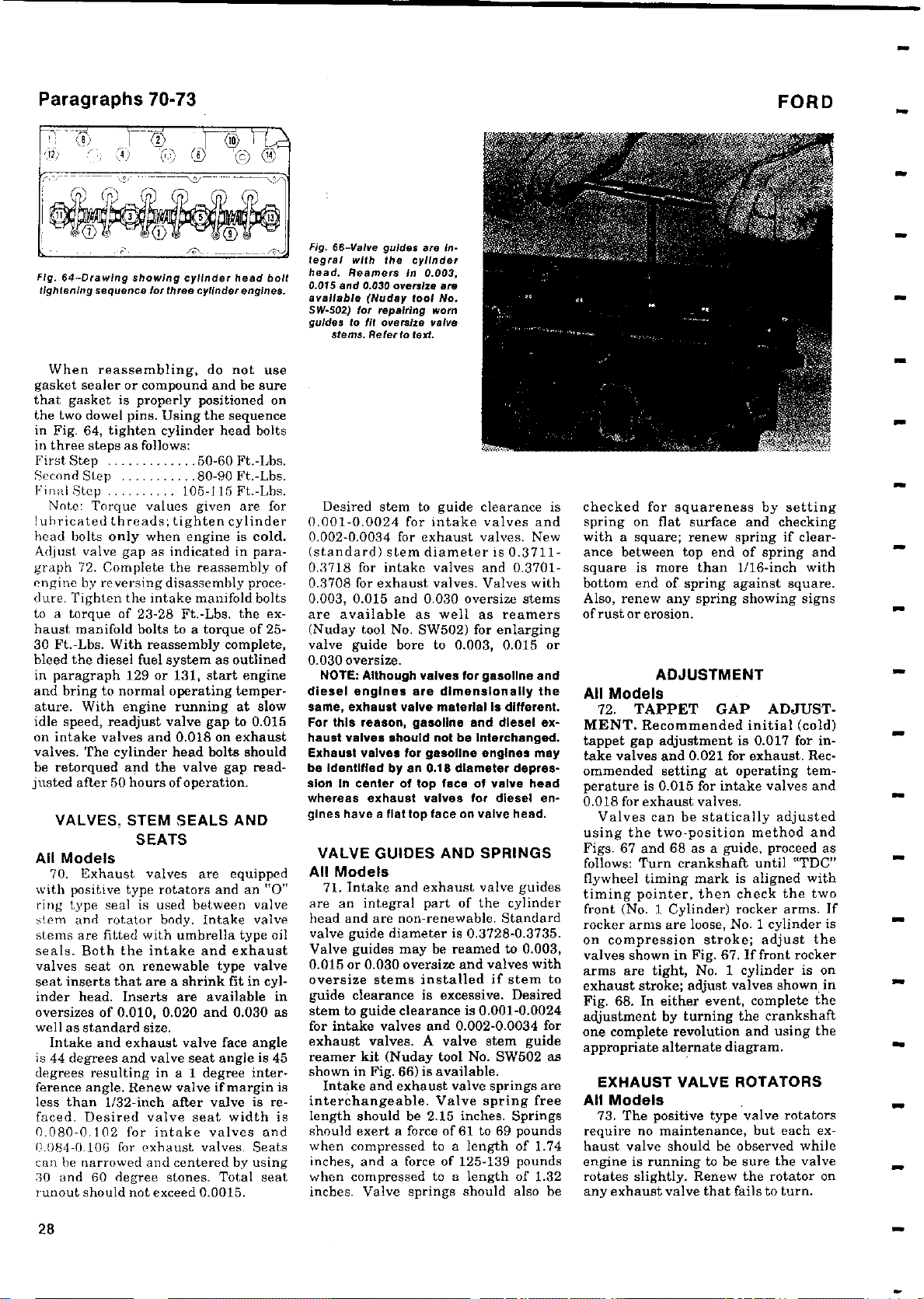
Paragraphs 70-73
FORD
U7) 4
1, o) CJ (c^ I7
X
'e Na
Fig.
64-Drawing
tightening
When reassembling, do not use
gasket sealer or compound and be sure
that gasket is properly positioned on
the two dowel pins. Using the sequence
in Fig. 64, tighten cylinder head bolts
in three steps as follows:
First Step ............. 50-60 Ft.-Lbs.
Second Step ........... 80-90 Ft.-Lbs.
Final Step .......... 105-115 Ft.-Lbs.
Note: Torque values given are for
Iuhricated threads; tighten cylinder
head bolts only when engine is cold.
Adjust valve gap as indicated in para-
graph 72. Complete the reassembly of
engine by reversing disassembly proce-
(lure. Tighten the intake manifold bolts
to a torque of 23-28 Ft.-Lbs. the exhaust manifold bolts to a torque of 2530 Ft.-Lbs. With reassembly complete,
bleed the diesel fuel system as outlined
in paragraph 129 or 131, start engine
and bring to normal operating temperature. With engine running at slow
idle speed, readjust valve gap to 0.015
on intake valves and 0.018 on exhaust
valves. The cylinder head bolts should
be retorqued and the valve gap read-
justed after 50 hours of operation.
VALVES,
All Models
70. Exhaust valves are equipped
with positive type rotators and an "0"
ring type seal is used between valve
stein and rotator body. Intake valve
stems are fitted with umbrella type oil
seals. Both the intake and exhaust
valves seat on renewable type valve
seat inserts that are a shrink fit in cylinder head.
oversizes of 0.010, 0.020 and 0.030 as
well as standard size.
Intake and exhaust valve face angle
is 44 degrees and valve seat angle is 45
degrees resulting in a 1 degree interference angle. Renew valve
less than 1/32-inch after valve is re-
faced. Desired valve seat width is
0.080-0.102 for intake valves and
0.084-0.106 for exhaust valves. Seats
can he narrowed and centered by using
30 and 60 degree stones. Total seat
runout should not exceed 0.0015.
showing cylinder
sequence
for three cylinder engines.
STEM SEALS AND
SEATS
Inserts
are available in
if margin is
head bolt
Fig.
66-Valve
tegral
head. Reamers in 0.003,
0.015 and 0.
available
SW-502)
guidestofit oversize valve
stems.
Desired stem to guide clearance is
0.001-0.0024 for intake valves and
0.002-0.0034 for exhaust valves. New
(standard) stem diameter is 0.3711-
0.3718 for intake valves and 0.3701-
0.3708 for exhaust valves. Valves with
0.003, 0.015 and 0.030 oversize stems
are available as well as reamers
(Nuday tool No. SW502) for enlarging
valve guide bore to 0.003, 0.015 or
0.030 oversize.
NOTE:Although valves for gasoline and
diesel engines are dimensionally the
same,exhaust valve material Is different.
For this reason,gasoline and diesel exhaust valves should not be Interchanged.
Exhaust valves for gasoline engines may
be Identified by an 0
sion In center of top face of valve head
whereas exhaust valves for diesel engines have a flattop face on valve head.
guides
with
the
cylinder
030 oversize are
(Nuday tool No.
for repairing worn
Refer to
text.
are in-
.
18 diameter depres-
VALVE GUIDES AND SPRINGS
All Models
71. Intake and exhaust valve guides
are an integral part of the cylinder
head and are non-renewable. Standard
valve guide diameter is 0.3728-0.3735.
Valve guides may be reamed to 0.003,
0.015 or 0.030 oversize and valves with
oversize stems
guide clearance is excessive
stem to guide
for intake
exhaust valves
reamer kit (Nuday tool No. SW502 as
shown in Fig.
Intake and exhaust valve springs are
interchangeable. Valve spring free
length should be 2.15 inches. Springs
should exert a force of 61 to 69 pounds
when compressed to a length of 1.74
inches, and a force of 125-139 pounds
when compressed to a length of 1.32
inches. Valve springs should also be
installed if stem to
clearance
valves
and 0.002-0.0034 for
. A valve stem guide
66) is available.
. Desired
is 0.001-0.0024
checked for squareness by setting
spring on flat surface and checking
with a square; renew spring if clearance between top end of spring and
square is more than 1/16-inch with
bottom end of spring against square.
Also, renew any spring showing signs
of rust or erosion.
ADJUSTMENT
All Models
72. TAPPET GAP ADJUST-
MENT
tappet gap adjustment is 0.017 for intake valves and 0.021 for exhaust. Recommended setting at operating temperature is 0.015 for intake valves and
0.018 for exhaust valves.
using the two-position method and
Figs. 67 and 68 as a guide, proceed as
follows: Turn crankshaft until "TDC"
flywheel timing mark is aligned with
timing pointer, then check the two
front (No. 1 Cylinder) rocker arms. If
rocker arms are loose, No. 1 cylinder is
on compression stroke; adjust the
valves shown in Fig. 67. If front rocker
arms are tight, No. 1 cylinder is on
exhaust stroke; adjust valves shown in
Fig. 68. In either event, complete the
adjustment by turning the crankshaft
one complete revolution and using the
appropriate alternate diagram.
All Models
require no maintenance, but each exhaust valve should be observed while
engine is running to be sure the valve
rotates slightly. Renew the rotator on
any exhaust valve that fails to turn.
. Recommended initial (cold)
Valves can be statically adjusted
EXHAUST VALVE ROTATORS
73. The positive type valve rotators
28
Page 29
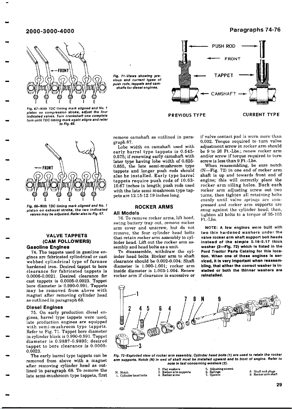
2000-3000-4000
Paragraphs 74-76
I E I E I E
timing mark aligned and No. 1
67-With
on
TDC
I E I E I E
68-With
TDC
compression
timing mark again aligns and refer
TDC timing mark
be
crankshaft one complete
Turn
.
to Fig. 68.
adjusted
adjust the four
,
stroke
aligned and
the two Indicated
,
Refer
also
.
to Fig. 67.
Fig.
piston
Indicated valves
turn until
Fig.
piston on exhaust stroke
valves may
VALVE TAPPETS
(CAM FOLLOWERS)
Gasoline Engines
74. The tappets used in gasoline en-
gines are fabricated cylindrical or cast
of furnace
webbed cylindrical
type
hardened iron. Desired tappet to bore
clearance for fabricated tappets is
0.0006-0.0021. Desired clearance for
cast tappets is 0.0005-0.0023. Tappet
bore diameter is 0.990-0.991. Tappets
may be removed from above with
magnet after removing cylinder head
as outlined in paragraph 68.
Diesel Engines
75. On early production diesel engines, barrel type tappets were used;
late production engines are equipped
with semi-mushroom type tappets.
Refer to Fig. 71. Tappet bore diameter
in cylinder block is 0.990-0.991. Tappet
diameter is 0.9887-0.9895; desired
tappet to bore clearance is 0.0005-
0.0023.
The early barrel type tappets can be
removed from above with a magnet
after removing cylinder head as outlined in paragraph 68. To remove the
late semi-mushroom type tappets, first
No. 1
4 PUSH ROD
Fig. 71
and current
vious
push rods,
shafts for
tappets
types of
cam-
and
diesel engines.
showing pre-
-Views
PREVIOUS TYPE
remove camshaft as outlined in paragraph 87.
Lobe width on camshaft used with
early barrel type tappets is 0.545-
0.575; if renewing early camshaft with
later type having lobe width of 0.825-
0.855, the late semi-mushroom type
tappets and longer push rods should
also be installed. Early type barrel
tappets require push rods of 10.63-
10.67 inches in length; push rods used
with the late semi-mushroom type tappets are 12.15-12.19 inches long.
ROCKER ARMS
All Models
76. To remove rocker arms, lift hood,
swing battery tray out, remove rocker
arm cover and unscrew, but do not
remove, the four cylinder head bolts
that retain rocker arm assembly to cylinder head. Lift out the rocker arm assembly and head bolts as a unit.
To disassemble, withdraw the cylinder head bolts. Rocker arm to shaft
clearance should be 0.002-0.004: Shaft
diameter is 1.000-1.001; rocker arm
inside diameter is 1.003-1.004. Renew
rocker arm if clearance is excessive or
1 8 N
2 4 5 6 4
3
.
Fig. 72-Exploded
arm
supports
N. Notch 3. Rocker arm supports
1. Cylinder head bolts 4. Rocker arm,
view of rocker
.
Notch(N) in
2. Flat washers
arm assembly
end of shaft must
note in text
Cylinder head
be Installed upward and to front of engine
concerning
^
1
FRONT
TAPPET -
+- CAMSHAFT -
^
^
CURRENT TYPE
if valve contact pad is worn more than
0.002. Torque required to turn valve
adjustment screw in rocker arm should
be 9 to 26 Ft.-Lbs.; renew rocker arm
and/or screw if torque required to turn
screw is less than 9 Ft.-Lbs.
When reassembling, be sure notch
(N-Fig. 72) in one end of rocker arm
shaft is up and towards front end of
engine; this will correctly place the
rocker arm oiling holes. Back each
rocker arm adjusting screw out two
turns, then tighten all retaining bolts
evenly until valve springs are com-
pressed and rocker arm supports are
snug against the cylinder head; then,
tighten all bolts to a torque of 95-105
Ft.-Lbs.
NOTE
two thin hardened washers under the
valve rocker arm shaft support bolt heads
Instead of the simple 0.16-0
washer(2-Fig. 72
Ford Tractor Parts Catalog for this location. When one of these engines is serviced
bling, that either the correct washer is in-
stalled or both the thinner washers are
reinstalled.
A few engines were built with
:
which Is listed In the
)
it is very Important when reassem-
,
bolts(1) are used to
washers (2).
5. Adjustingacrewe
6. Springs 8. Shaftendplugs
7. Spacer 9
.
retain the
Rocker arm shaft
.
17 thick
rocker
Refer to
.
29
Page 30
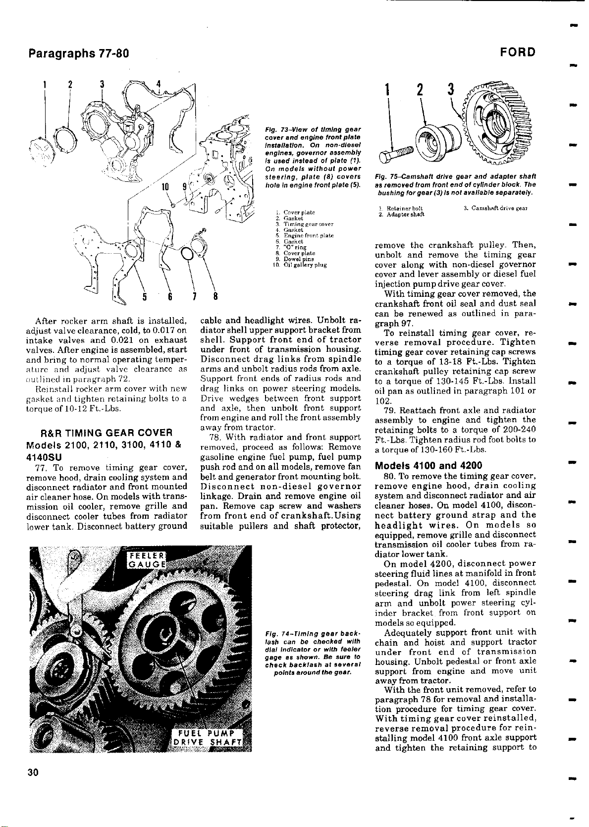
Paragraphs 77-80
FORD
After rocker arm
adjust valve clearance
intake valves and 0
valves.
and bring
engine is assembled, start
After
to normal operating temper-
ature and adjust valve
shaft is installed,
,
cold, to 0.017 on
021 on exhaust
.
clearance as
outlined in paragraph 72.
Reinstall rocker arm cover with new
gasket and tighten retaining bolts to a
torque of 10-12 Ft.-Lbs.
R&R TIMING GEAR COVER
Models 2100, 2110
, 3100, 4110 &
4140SU
77. To remove timing gear cover,
remove hood, drain cooling system and
disconnect radiator and front mounted
air cleaner hose. On models with trans-
mission oil cooler, remove grille and
disconnect cooler tubes from radiator
lower tank. Disconnect battery ground
Fig. 73-View of timing gear
cover and
Installation
engines
is used instead
steering
r 2. Gask t^
cable and headlight wires. Unbolt radiator shell upper support bracket from
shell. Support front end of tractor
under front of transmission housing.
Disconnect drag links from spindle
arms and unbolt radius rods from axle.
Support front ends of radius rods and
drag links on power steering models.
Drive wedges between front support
and axle, then unbolt front support
from engine and roll the front assembly
away from tractor.
78. With radiator and front support
removed, proceed as follows: Remove
gasoline engine fuel pump, fuel pump
push rod and on all models, remove fan
belt and generator front mounting bolt.
Disconnect non-diesel governor
linkage. Drain and remove engine oil
pan. Remove cap screw and washers
from front end of crankshaft. Using
suitable pullers and shaft protector,
lash can be checked
dial indicator or with feeler
gage as
check
FUEL PUMP
DRIVE SHAFT
engine front
On non-diesel
.
governor assembly
,
On models without
holeinengine
Fig. 74-
,
plate
front
3. I'ming gear cover
4 Gasket
5. Engine front. plate
5. Gasket
], a g
8. Cove' plate
9. Dowel in
to. Oil gallery plug
Timing
shown
backlash
points around the gear.
of plate (1).
power
8) covers
(
plate (5).
gear back-
.
Be sure
at several
plate
with
Fig.
75-Camshaft
removed from front end of cylinder
as
for
bushing
I. Retainer bolt
2. Adapter shaft
drive gear and adapter
(3) is
not available
gear
remove the crankshaft pulley. Then,
unbolt and remove the timing gear
cover along with non-diesel governor
cover and lever assembly or diesel fuel
injection pump drive gear cover.
With timing gear cover removed, the
crankshaft front oil seal and dust seal
can be renewed as outlined in paragraph 97.
To reinstall timing gear cover, reverse removal procedure. Tighten
timing gear cover retaining cap screws
to a torque of 13-18 Ft.-Lbs. Tighten
crankshaft pulley retaining cap screw
to a torque of 130-145 Ft.-Lbs. Install
oil pan as outlined in paragraph 101 or
102.
79. Reattach front axle and radiator
assembly to engine and tighten the
retaining bolts to a torque of 200-240
Ft.-Lbs. Tighten radius rod foot bolts to
a torque of 130-160 Ft.-Lbs.
Models 4100 and 4200
80. To remove the timing gear cover,
remove engine hood, drain cooling
system and disconnect radiator and air
cleaner hoses. On model 4100, disconnect battery ground strap and the
headlight wires. On models so
equipped, remove grille and disconnect
transmission oil cooler tubes from radiator lower tank.
On model 4200, disconnect power
steering fluid lines at manifold in front
pedestal. On model 4100, disconnect
steering drag link from left spindle
arm and unbolt power steering cylinder bracket from front support on
models so equipped.
Adequately support front unit with
chain and hoist and support tractor
under front end of transmission
to
housing. Unbolt pedestal or front axle
support from engine and move unit
away from tractor.
With the front unit removed, refer to
paragraph 78 for removal and installation procedure for timing gear cover.
With timing gear cover reinstalled,
reverse removal procedure for reinstalling model 4100 front axle support
and tighten the retaining support to
block.
separately.
3. Camshaft drive gear
shaft
The
30
Page 31

2000
3000-4000
-
Fig. 76-View
marks on
camshaft
gear and distributor
drive
drivegear
Identic
alon
showing
crankshaft gear,
,
camshaft
gear
marks
timing
;
diesel
engines.
timing
are
Paragraphs 81-87
marks; small burrs can be removed
with fine carborundum stone.
To reinstall the camshaft drive gear,
turn crankshaft so that No. 1 piston is
at top dead center on compression
stroke and turn camshaft and fuel
injection pump drive gear or distrib-
utor drive gear so that timing marks
point to center of camshaft drive gear
location. Place the camshaft drive gear
within the other three gears so that all
timing marks are aligned as shown in
Fig. 76, then install the adapter (shaft)
and tighten the self-locking cap screw
to a torque of 100-105 Ft:-Lbs.
Fig. 77-Drawing
to camshaft
gear
diesel
engines
1. Cap screw 5. Cap screws(2)
2. Inckwaeher 6. Thrust plate
3. Flat washer (diesel) 7. Spacer
3A. Eccentric Shaft 9. Camshaft
4. Camshaft gear 10. Woodruff key
showing
; fuel pump eccentric (3A) is
on gasoline engines.
assembly
(
.
Fiat
washer
3) is used on
engine bolts to a torque of 200-240 Ft.Lbs., drag link nut to a torque of 55-65
Ft.-Lbs. and the power steering cylinder bracket bolts to a torque of 200250 Ft.-Lbs. On model 4200, refer to
paragraph 52 for shimming procedure
when reinstalling front pedestal.
TIMING GEARS
All Models
81. Before removing any gears in the
timing gear train, first remove rocker
arms assembly to avoid the possibility
of camshaft
used
of damage to piston or valve train if
either the camshaft or crankshaft
should be turned independently of the
other.
The timing gear train consists of the
crankshaft gear, camshaft gear, injection pump drive gear or distributor
drive gear and a camshaft drive gear
(idler gear) connecting the other three
of the train. Refer to Fig. 76.
gears
Timing gear
crankshaft
, or between camshaft drive gear
gear
and camshaft
0.006 on gasoline
0.009 on diesel engines.
backlash between
gear and camshaft drive
'llhould be 0.001-
gear
engines and 0.001-
Backlash between camshaft drive gear
injection pump drive gear or distributordrive
gear should
If backlash is hot within
limits,
renew the camshaft drive gear,
be-0.001-0.012.
recommended
camshaft drive gear shaft and/or any
other gears concerned.
83. CAMSHAFT' DRIVE GEAR
AND SHAFT. To remove; unscrew the
self locking cap screw and remove
the camshaft drivpgear and shaft
(adapter) from front face of cylinder
block. Renew shaft and/or gear if
bushing to shaft clearance
is excessive,
or if gearing surfaces are scored. In-
spect gear
teeth for wear or score
and fuel
84. CAMSHAFT GEAR. To remove
, retngye cap screw (1
the camshaft
gear
-Fig. 77), lockwasher (2) and washer
(3) on diesel models or fuel pump eccentric (3A) on gasoline models; then, pull
gear from shaft. Gear should be a hand
push fit on shaft. With gear removed,
inspect drive key (10), thrust plate (6)
and spacer (7) and renew if damaged in
any way.
To reinstall gear, first install spacer,
thrust plate and drive key, then install
gear, washer or gasoline fuel pump
eccentric, lock washer and gear retaining cap screw, Tighten the cap
screw to a torque of 40-45 Ft.-Lbs.
85. CRANKSHAFT GEAR. If not
removed with timing gear cover and
seal assembly
, slide the spacer (5-Fig.
78) from crankshaft; then, using
remover-replacer (Nuday tool No. SW-
501) and insert (Nuday tool No. SW501-1) or equivalenttool, pull gear
from crankshaft. Inspect the gear and
crankshaft pulley drive key (3) and
renew if damaged
To reinstall
in any way.
gear,
first drive the key
(3) into crankshaft keyway until fully
seated, then install the gear with
timing mark outward using removerreplacer tools as used in removal procedure, or push gear onto shaft with bolt
threaded into front end of crankshaft
and using nut, large washer and a
sleeve.
86. FUEL INJECTION PUMP OR
DISTRIBUTOR DRIVE GEAR. For
diesel models, refer to paragraph 157.
On gasoline models,
refer to paragraph
167 for information concerning distributor drive unit and governor.
1. Capscrew
2. Flat washer
3. Drive key
4. Crankshaft pulley
5. Spacer
6. Dust seal
7. Oil seal.
8. Oil clinger
9. Crankshaft gear
12. Crankshaft
Fig.
76-Crankshaft
staliqtlon is shown for all
models.Dust teal
5041 (7) are pressed
groin ,gear cover
side and ride
production tractors;
late
on
on
early
units, dust seal
oil seal
ride on
pulley hub.
(6)
on spacer (5)
crankshaft
gear
and pit
into
from In-
and
in-
CAMSHAFT AND BEARINGS
All Models
87. To remove camshaft, first remove
engine as outlined in paragraph 66 and
timing gear cover as outlined in paragraph 78. On gasoline engines and on
diesel engines with early barrel type
tappets, remove cylinder head as in
paragraph 68, then lift tappets (cam
followers) from openings in top of cyl-
inder block with a magnet. On diesel
31
Page 32

Paragraph
Fig. 80-Exploded view drawing of camshaft,
controlled by thrust plate (6).
is
camshaft
3A. Fuel pump eccentric
journals.
1. Cap'crew 5.
2 Lockwaeher
3. Flat washer 7. Spacer 11
4 Camshaft gear
87 Cont.
used on
gasoline models.
camshaft
diesel
Washer (3) Is
Renewablecamshaft
Cap screws(2) 9. Camshaft
6. Thruetplate 10. Woodrufrkey
8. Camshaft bearing 12. Hydraulic lift pump
gear and hydraulic pump drive
bearings (8) are
models;
fuel pump
. Dowel pin
drive gear
engines with late semi-mushroom type Using a feeler gage or dial indicator,
tappets, remove rocker arm assembly measure camshaft end play. Desired
and push rods, then invert engine as- end play is 0.001-0.007. If end
sembly to allow cam followers to fall excessive, renew thrust plate during
away from camshaft. Note: On diesel
engines, measure push rods before
removing cylinder head; if push rods
are approximately 10'/2 inches long,
engine is equipped with early barrel
type
tappets. If diesel engine push rods
are approximately 12 5/32 inches long,
engine is equipped
with
semi-mush-
room type tappets. Remove clutch, flywheel
and engine rear plate
the hydraulic pump drive
from rear end of cylinder block (
not equipped
with piston
and push the camshaft rear cover plate
from cylinder
block with punch (Fig.
.
Remove
gear cover
models
type pump)
Fig.
81-Camshaft
plate can be
punch
after
wheel
,
rear engine
hydraulic pump.
removed with a
removing fly-
81). Remove the oil filter and oil pump
drive gear (Fig. 95); on diesel engine,
the oil pump drive shaft should be removed with gear on engine inverted in
stand.
Fig. 79
remover-replacer
tool No.SW501
crankshaft gear
gear
tector(SP)
threaded shaft Is
Into end
nut (N7
used in
rear
plate and
-
Using special
,
nut (N2)and shaft pro-
of crankshaft and
)
is turned to push
gearontoshaft.
cylinder block for all
eccentric (3A) Is used
13. Cuscrew
14. "0
15. Hydraulic pump
cover
(Nuday
)
to
remove
.
To install
are removed,
screwed
End play
gear
.
r
m(early)
drive gear cover
play
FORb
reassembly. Remove the cap screw (1Fig. 80), lock washer (2) and flat
washer (3) (diesel models) or the fuel
pump eccentric (3A) (gasoline models)
and pull the camshaft gear from shaft.
Remove the Woodruff key (10); thrust
plate (6) and spacer (7). Withdraw
camshaft and hydraulic pump drive
gear from rear of cylinder block, then
remove pump drive gear if necessary.
The camshaft is supported in four
bushing type bearings. Check camshaft
and bearings against.the following
values:
Camshaft journal
diameter
Desired journal
clearance
Camshaft end play ....... 0.001-0.007
If excessive bearing wear is indicated, the bearings can be removed and
new bearings installed with bearing
driver (Nuday tool No. SW 506) and
handle (Nuday tool No. N6261-A) or
equivalent tools. Note: It will be necessary to invert engine and remove oil
pan to remove and ihistall bearings.
Pay particular attention that the oil
holes in bearings are aligned with the
oil passages in cylinder block. New
bearings are pre-sized and should not
require reaming if carefully installed.
Reinstall camshaft by reversing
removal procedure. Tighten the hydraulic pump drive gear retaining cap
on
screw to a torque of 40-45 Ft.-Lbs.,
tighten thrust plate cap screws to a
torque of 12-15 Ft.-Lbs. and tighten the
camshaft gear retaining cap screw to a
torque of 40-45 Ft.-Lbs. Place hydraulic drive gear cover "0" ring
(models prior 8-67) in groove in cylinder block, lubricate the "0" ring and
push cover into place as shown in Fig.
is
83. Note: Be sure that camshaft gear is
timed as shown in Fig. 76.
........... 2.3895-2.3905
to bearing
..............0.001-0.003
32
Page 33

2000
3000-4000
-
Paragraphs 88-91
Fig.82-
View showing
and installing
bearings are installed
Fig. 83-Installing the hydraulic pump drive
cover plate
CONNECTING
ROD AND CAP
Fig. 84
of piston to connecting rod;
necting
numbers facing either
stalled with notch or number
oil holes In
15-Fig
(
NUMNENS
View showing recommended
-
rod can be Installed
camshaft
.
longer
special
bearings
with
cylinder
80). Note
used.
way.Piston must be In-
gine.
for removing
tool
Be sure that
.
oil holes aligned
block.
0" ring is no
: "
NOTCH ON e,'
NuMUtR oN
PINT 9
however, con-
on crankshaft with
to the
front of
with
gear
assembly
en-
-diesel
showing
(gaso-
pistons.
85-Views
Fig.
proper Installation of piston
rings on non
tine) and diesel
CONNECTING ROD AND
PISTON UNITS
All Models
88. Connecting rod and piston units
are removed from above after removing
the cylinder head and oil pan. Be sure
to remove top ridge from cylinder bores
before attempting to withdraw the as-
semblies.
Connecting rod and bearing cap are
numbered to correspond to their respective cylinder bores. When renewing the connecting rod, be sure to
stamp the cylinder number on new rod
and cap.
When reassembling, it is important
that the identification number or notch
in top face of piston is towards the front
end of engine. It is standard practice to
assemble connecting rod to piston with
cylinder numbers to right side of en-
gine (away from camshaft); however,
the rod is symmetrical and rod can be
installed with numbers in either direction (away from or towards camshaft)
without affecting performance or durability of engine.
li
When installing connecting rod cap,
be sure that bearing liner tangs, and
the cylinder identification number, of
rod and cap are towards same side of
engine. Tighten the connecting rod
nuts to a torque of 60-65 Ft.-Lbs.
PISTON RINGS
Non-Diesel Engines
89. Each cam ground piston is fitted
with two compression rings and one oil
control ring. Top compression ring and
oil control ring are chrome plated. Top
compression ring is barrel face type
and must be installed with identifica-
tion mark up. Second compression ring
has straight face with inner bevel and
must be installed with groove on inside
diameter up. The oil control ring and
oil ring expander may be installed either side up,
Piston ring sets are available in
oversizes of 0.020, 0.030 and 0.040 as
well as standard size. The standard size
rings are to be used with both grades of
standard size pistons and with 0.004
e*SOtIN
:XPANOfR--'
vrl„
DIESEL
oversize pistons. Refer to the following
specifications for checking piston ring
fit:
Ring End Gap:
Top compression ring ..... 0.012-0.038
Second compression ring ..0.012-0.035
Oil control ring ..........0.013-0.038
Ring Side Clearance In Groove:
Top compression ring .. 0.0029-0.0046
Second compression
ring 0.0025-0.0045
Oil control ring ....... 0.0024-0.0041
Diesel Engines
90. Pistons are fitted with three
compression rings and one oil control
ring. The two top compression rings
and the oil control ring are chrome
plated. Top compression ring is barrel
face type and must be installed with
identification mark up. Second and
third compression rings have straight
face with bevel on inside diameter and
must be installed with beveled side up.
The oil control ring and expander may
be installed with either side up.
Piston ring
oversizes
well as standard
rings
are to be used with both grades of
standard
sets
are available in
of 0.020, 0.030 and 0.040 as
. The standard size
size
size
pistons and also with
0.004 oversize pistons. Refer to the following specifications for checking
piston ring fit:
Ring End Gap:
Top compression ring ..... 0.012-0.038
Second & third compression
rings .................. 0.012-0.035
Oil control ring .......... 0.013-0.038
Ring Side
Clearance In Groove:
Top compression ring .. 0.0044-0.0061
Second & third compression
rings ............... 0.0039-0.0056
Oil control ring ....... 0.0024-0.0041
PISTONS AND CYLINDERS
All Models
91. Non-diesel
ground aluminum alloy pistons with a
cast iron insert containing the top ring
groove. Diesel engines have trunk
aluminum alloy pistons with a continuous skirt and a Ni-Resist insert con-
taining the top ring groove. Early design pistons were straight in the upper
engines
have cam
type
33
Page 34

Paragraphs 92-94
099. 10 100'
Fig. 86
-
Top of installed sleeve flange should be
flush
to 0
.
002 above gasket surface
shown.
land area; whereas, later production
and service platens are tapered in the
upper land area.
Cylinder
normally
bores in engine block are
unsleeved;however,repair
sleeves have been factory installed in
engines with 4.2 inch diameter cylin-
ders. In factory
installation
ders are, sleeved, and block is stamped
"SB" on left side
Series 4000
available for
oil pan flange.
(
tractors
4.4 bore) have
service a thin wall cast
sleeve which is not used in production
and which cannot be overbored.
Pistons, pins and rings are available
in standard size and 0.004 oversize for
use in standard
0.020, 0.030
bored
blocks.
bores, and oversizes of
and 0.040 for use in re-
92. INSTALLING SLEEVES. To
install sleeves in unsleeved 4.2 inch
bore engines, finish-bore the block to
an inside diameter of 4.358. Selectively
fit the sleeves to provide, as nearly as
possible the optimum 0.004 interfer-
ence fit for all sleeves.
Thoroughly clean and dry the sleeve
and bore and carefully apply a 3-inch
hand of LOCTITE Sleeve Retainer
rgreen) to top of bore. Install sleeve,
outside chamfered edge down and press
into position until top of sleeve is flush
to 0.001 above block surface. Allow
block to cure overnight before com-
pleting the assembly. Re-examine the
installation and mill the block if necessary, to provide correct sleeve height.
NOTE: DO NOT remove more than
0.005 from top surface. Finish bore and
hone the sleeve after milling, to 4.200-
4.2024 for standard piston or to the
appropriate oversize if oversize piston
is installed. Refer also to paragraph 93
for additional data on piston and ring
installation.
The flanged, thin-wall cast sleeves
used in 4.4 inch diameter bore engines
can be used only with standard size or
0.004 oversize pistons, and cannot be
re-hored. Thin wall sleeves are a light
press fit in engine block and should be
installed as follows:
First make sure that sleeve and
of
all cylin-
,
block as
Fig.
87-Three
been
and two different crown
bore diesel
height to
block bore are clean and
dry.
sleeves for 15 minutes in dry ice and
used
In 4.4 Inch
engines
be
Chill the
different Crown h
sure correct
bore gat bline, engines;
heights
.
If In
doubt,measure
pistdn Is being In-
stalled.
piston by honing, rebore cylinder to
0.020 oversize.
push the sleeve as far as possible into
block bore. Seat the sleeve, if necessary, using'a puller and suitable in-
stalling plate. Top of installed sleeve
flange 'hould be flush to O.Od2 above
gasket surface of block as shown in Fig.
86. Machining dimensions for installing sleeves in unbored block are
shown in Fig. 86.
NOTE:
Indpr
wafer and detergent until a white cloth
calf be rubbed against cylinder wall
wlthdbt smudging,then rinse
water, dry
rusting.
All pistons used in 4.4 inch bore en-
93. FITTING PISTONS. Recom-
mended method
follows:
glaze cy
. Before checkingpiston fit, de-
l
inder wall using a hone or deglazing.tool
sure
pdton diameter
for fitting
.
Using a micrometer, mea-
Oistons is as
at centerline of
and at right angle to the piston pin
bore. Then,
using an inside microme-
ter, measure cylinder bore diameter at
a distance of 2'4 inches from top of cyl-
gines are not interchangeable. In
April,1968,Series 4000 gasoline en-
gine strdke was increased from 4.2 to
4.4 iches.
height(measured from top of piston pin
as shown at H-Fig
from 1
wrong piston could result in piston to
cylinder head contact or decreased
compression.
inder block crosswise with the block.
Subtract the piston diameter from the
cylinder bore diameter; the resulting
piston to cylinder bore clearance
should be Within the following specification for proper piston fit:
All Models
94. The 1.4997-1.5000 diameter
floating type piston pins are retained
in the piston pin bosses by snap rings
Non-Diesel Engines:
4.2 Inch Bore ......... 0.0027-0.0037
4.4 Inch Bore ......... 0.0032-0.0042
Diesel Engines:
4.2 Inch Bore ......... 0.0075-0.0085
4.4 Inch Bore ......... 0.0080-0.0090
and are available in standard size only.
Piston pin should have a clearance of
0.0005-0.0007 in connecting rod
bushing and a clearance of 0.0003-
0.0005 in piston bosses. After installing new piston pin bushings in
connecting rods, the oil hole in bushing
must be drilled as shown in Fig. 88 and
the.,bushings final sized with a spiral
Note:
Two grades of standard pistons
are available.Grade "D
standard size
"
pistons(color coded blue) are larger in
diameter
piston (color coded
than grade
"B" standard size
red). If grade "D"
piston fits too loosely in standard cylinder bore, try a 0.004
oversize piston.
If not possible to fit the 0.004 oversize
expansion reamer to obtain the speci-
fied pin to bushing clearance. Bushing
inside diameter should then be 1.5003-
1.5006. When assembling, identification notch or number in top face of
piston must be to front end of engine
and the identification, number oh rod
and cap towards right side of engine
H) have
Ights
(
ee,,
4.4 Inch
used on
bore,wash bore
crown
After honing or deglazing cyl.
thoroughly
thoroughly and oil to prevent
At that time piston crown
.
.
992 to 1.774
87) was decreased
Installation of the
.
PISTON PINS
FORD
with hot
with cold
34
Page 35

2000
(away from camshaft); however, the
rod is symmetrical and can be installed
either way without affecting engine
performance or durability.
All Models
cision type, renewable from below after
removing the oil pan and connecting
rod bearing caps. When removing
bearing caps, note which way that cyl-
inder identification numbers are
placed on each rod assembly. It is stan-
dard practice that the numbers face
away from the camshaft side of engine;
however, the connecting rods are symmetrical and may be placed with iden-
tification numbers to either side of en-
gine. It is very important that the pistons be placed in cylinder bore with the
identification number or notch in top
face of piston towards front end of engine; therefore, do not attempt to realign rod identification numbers if they
are to camshaft side of engine.
two different materials, copper-lead or
aluminum-tin alloy. The bearings will
have an identification marking as follows:
Copper-lead
Aluminum-tin ............. G and AL
material are available in two different
thicknesses and are color coded to indicate as follows:
Copper-lead bearing thickness:
Red .................. 0.0943-0.0948
Blue ................. 0.0947-0.0952
Aluminum-tin alloy bearing
thickness:
Red .................. 0.0939-0.0944
Blue ................. 0.0943-0.0948
crankshaft crankpin journals are color
coded to indicate bore and journal di-
ameters as
bore diameter:
Red .................. 2.9412-2.9416
Blue .................. 2
Crankpin journal diameter:
Red .................. 2.7500-2.7504
Blue ................. 2
When installing a new crankshaft and
the color code marks are visible on
connecting rods, the crankpin bearing
liners may be fit as follows: If the color
code markings on both rod and crankshaft crankpin journal are red, install
two red bearing liners; if both color
3000-4000
-
CONNECTING RODS AND
BEARINGS
95. Connecting rod bearings are pre-
Crankpin bearing liners may be of
................ PV or G
Standard
In production, connecting rods and
size
bearing liners of each
follows: Connecting rod
.9416-2.9420
.7496-2.7500
Fig.88necting rod bushing
drilled after bushing Is in-
stalled
or honing bushing
code markings are blue, install two
blue coded
marks on rod
match (
install one red and one blue bearing
liner. Note:. Be sure that both bearing
liners are of the same material; that is,
either both are copper-lead or both are
aluminum-tin alloy. If color code mark
is not visible on connecting rod or
crankshaft, bearing fit should be
checked with plasti-gage for the proper
clearance according to bearing material as follows:
Crankpin journal to bearing liner
clearance:
red-coded or blue-coded standard size,
bearing liners are also available in
undersizes
and 0.040. When installing undersize
crankpin bearing liners
must be reground to one of the following exact undersizes:
Bearing Crankpin
Undersize Journal Dia.
NOTE: When regrinding crankpin
journals
radius and
journal is ground to size.
connecting
Ft.-Lbs.
All Models
main bearings. Crankshaft end thrust
is controlled by the flanged main
bearing liner which is used on the
second main journal from front. Before
removing main bearing caps, check to
hole in con-
Oil
but before reaming
,
one is red
Copper-lead bearings 0.0017-0.0038
Aluminum-tin
bearings ......... 0.0025-0.0046
As well as being available in either
0.002
0.010
0.020
0.030
0.040
, maintain a 0.12-0.14 fillet
When reassembling
must be
to
fit pin.
bearing liners
and crankpin do not
and the other is blue)
of 0.002, 0.010, 0.020, 0.030
. If color code
, the crankpin
2.7476-2.7484
2.7396-2.7404
2.7296-2.7304
2.7196-2.7204
2.7096-2.7104
chamfer oil hole after
, tighten the
rod nuts to a torque of 60-65
CRANKSHAFT AND MAIN
BEARINGS
96. Crankshaft is supported in four
Paragraphs 95-96
see that they have an identification
number so that they can be installed in
same position from which they are
removed.
Main bearing liners may be of two
different materials, copper
aluminum-tin alloy. The bearings will
have an identification marking to indicate bearing material as follows:
Copper-lead
Aluminum-tin
Standard size bearing liners are available in two different thicknesses and
are color-coded to indicate
follows:
Red .................. 0.1245
Blue ................. 0.1249-0.1254
In production,main bearing bores in
block and main bearing journals on
crankshaft are color coded to indicate
bore and journal diameter as follows:
Main bearing bore diameter:
................ PV or G
alloy ........ G and AL
Red ................ 3.6242-3.6246
Blue ............... 3
Main journal diameter:
Red ................ 3
Blue ............... 3.3713-3.3718
When installing a new crankshaft
and the color code marks are visible in
crankcase at main bearing bores, new
main bearing liners may be fit as follows: If the color code marks on bore
and journal are both red, install two
red coded bearing liners; if both marks
are blue, install two blue coded bearing
liners. If color code mark on bore is not
the same as color code on journal (one
is blue and the other is red), install one
red coded bearing liner and one blue
coded bearing
liners used
same material
bearing liners may be used on one or
more journals with aluminum-t}n alloy
liners on the
color code marks are not visible at the
main bearing bores in block, check
bearing fit with plastired or blue, or one red and one blue
liner to obtain a bearing journal to
liner clearance of 0.0022-0.0045. Note:
Recommended clearance is for either
copper-lead or aluminum-tin alloy
bearing material.
liner. Note: Be sure both
at one journal are of the,
however, copper-lead
remaining
gage
-
lead or
thickness as
-0.1250
6246-3.6250
.
.
3718-3.3723
journals. If
and install
35
Page 36

Paragraphs 97-98
ENGINE
FRONT
COVER
630-16 STEP PLATE
Fig. 90-Installing the crankshaft front oil seal in
engine timing
gear cover.
Fig.89showing
ings and related
three
I. Cap screw
2. Flat schr,
3. Drive key
4 Crankshaft pulley
5. Spacer
6. Dust seal
7. Oil seal
S. 0' 1 Olin
9. Crankshaft gear
10. Main bearing liners
11. Thrust
12. Crankshaft
13. Rear it seal
14. Flywheel assembly
15. Rear bearing cap
scale
As well as being
available
red-coded or blue-coded
new main bearing
liners are also avail-
able in undersizes of 0.002, 0.010,
0.020, 0.030 and 0.040. When installing undersize main bearing liners,
the crankshaft journals must be reground to one of the following exact
undersizes:
Bearing
Undersize
0.002 3.3694-3.3702
0.010 3.3614-3.3622
0.020 3.3514-3.3522
0.030 3.3414-3.3422
0.040 3.3314-3.3322
211
NOTE: When regrinding crankshaft
main bearing journals, maintain a
fillet radius of 0.12-0.14 and chamfer
oil holes after journal is ground to size.
When reinstalling main bearing
caps, proceed as follows: Be sure the
Exploded
crankshaft,bear-
cylinder engine.
parts
bearing liners
in either
standard size,
Main
Journal Diameter
bearing bores and rear main bearing
oil seal area
fore installing bearing liners
tangs on bearing inserts are in the slots
provided
in cylinder block and bearing
caps. Refer to paragraph 99 for rear cap
view
side seals
a torque of 115-125 Ft.-Lbs.
for
.
Tighten bearing
CRANKSHAFT OIL SEALS
All Models
97. FRONT OIL SEAL. Crankshaft
front oil seal is mounted in timing gear
cover and cover must be removed to
renew seal. Timing gear cover removal
procedure is outlined in paragraph 77
or 80. To renew seal, drive dust seal
and oil seal out towards inside of
timing gear cover. Install new dust seal
in timing gear cover first, then using a
seal driver (OTC No. 630-16 step plate
or equivalent), install new oil seal in
cover with spring loaded lip towards
inside of cover. Refer to Fig. 90.
On early production engines, the
crankshaft front seal rides on the
crankshaft pulley hub; later production
engines are fitted with a revised crankshaft pulley and pulley spacer so that
the oil seal rides on the spacer instead
of pulley hub. Carefully inspect pulley
hub (early production) or pulley spacer
(later production) for wear at seal contact surface and renew pulley or spacer
if wear or scoring is evident. Note: later
production crankshaft pulley and
spacer can be installed on early produc-
tion engine if desired.
98. REAR
rear
oil seal can
moving clutch assembly, flywheel and
engine rear
bore in cylinder block and rear main
bearing cap and thoroughly clean
crankshaft seal journal. Apply a light
coat of high temperature
bore, crankshaft
and the outside diameter of seal. Install new seal with a 43'a inch I.D.
sleeve so that rear face of seal is 0.060
plate. Pry old seal from
are thoroughly
.
cap bolts to
OIL SEAL. Crankshaft
be renewed after re-
grease to seal
seal journal
, lip of seal
FORD
clean be-
Be sure
Fig. 91-
36
Installing rear oil
stallation tool.
seal
using
special
Fig. 92-Installing rear main
bearing cap and side seals.
in-
Page 37

2000
3000-4000
-
Paragraphs 99-102
Fig. 95-Removing the oil pump drive gear and
shaft assembly
drive gear and shaft assembly
can be
.
Floating
removed et this time
shaft connecting the
to
oil pump
Refer
Fig. 96.
to
.
below flush with rear face of block.
Using a dial indicator, check runout of
; runout should not ex-
rear face
ceed 0.015. A
tool (Nuday tool No. SW 520)
able; using three flywheel
of seal
special seal installation
is avail-
bolts, press
seal in with tool until flange on tool
bottoms and tighten the bolts to 25 Ft.Lbs. Then, remove bolts and seal installation tool. Note: Some early
models may have a stop installed in
front of seal; if so remove and discard
stop before
99. To install
cap side
ceed as follows:• Place side
grooves of
inch from top
installing new seal.
new rear main
remove the cap and pro-
seals,
they extend about S -
cap so
surface
bearing
seals in
(see Fig. 92).
Apply sealing compound to top face of
cap making sure chamfers
cap are
the bearing
covered.
Insert and
, then install cap and
liner
on edge of
lubricate
tighten retaining bolts to torque of 115-
into block so
125 Ft.-Lbs. Tap side
seals
that they extend about 0.005-0.15 from
block and cap. With rear cap and side
rotor
Fig. 93-Bottom
Iron oil pan
dustrial
models.Engine
port attaching
a definite shimming
dure
appropriate front support
rowcrop
,
which
removal
points
is outlined in
paragraph.
seals installed, soak side seals with
penetrating oil and install rear oil seal
as in paragraph 98.
FLYWHEEL
All Models
100. The flywheel can be removed
after splitting tractbr between engine
and transmission and removing the
clutch or Select-O-Speed torque limiting clutch. Flywheel can be installed
in one position only. On models with
clutch, the flywheel retaining cap
screws also retain the clutch shaft pilot
bearing retainer. When reinstalling
flywheel, tighten the retaining cap
screws to a torque of 100-110 Ft.-Lbs.
Starter ring gear is installed from
front face of flywheel; therefore, the
flywheel must be removed to renew the
ring gear. Heat the gear to be removed
with a torch from front side of gear and
knock gear off of flywheel. Heat new
gear evenly until gear expands enough
to slip onto flywheel. Tap gear all the
way around to be sure it is properly
seated and allow it to cool. Note: Be
sure to heat gear evenly; if any portion
of gear is heated to a temperature
higher than 500° F., rapid wear will
result. Ring gears for diesel engines
have 128 teeth; those for gasoline engines have 162 teeth.
OIL PAN (SUMP)
Models 2100
&
4110
removed without removing other components. Be sure that gasket surfaces
of engine block, timing gear cover and
pan are clean and that pan rim is flat.
If removed, reinstall timing gear cover
prior to reinstalling oil pan. Cement
gasket to pan rim with thin film of
4140SU
101. The oil pan can be unbolted and
2110,3100, 4100,
,
of cast
view
used on In-
,
and utility
front sup-
require
proce-
118
-®
17A ---qGP
L
3
2
Fig. 96-Exploded view of oil pump
and drive gear assembly
Refer to FIg.95
(18), drive gear
shah
(13) may be
1. Retainer clip
2. Screen 12
3. Screen cover 13. Floating shaft
4. Pump cover
5. Rotor at 15. Drive gear
6. Plug 16. Pin
9. Relief valve spring 17. Gasket
8. Relief valve
9. Capserevt
10. Retainer washer
for removal of early type
15) and shaft
(
removed
above.
gasket sealer. Tighten retaining cap
screws finger tight and, if engine is
removed, be sure that pan does not extend beyond rear face of block. Starting
from middle of pan, tighten cap screws
to a torque of 20-25 Ft.-Lbs.
Model 4200
102. On models with cast iron pan
(see Fig. 93), the front support assembly must be removed prior to re
moving oil pan. Refer to paragraph 80
for model 4200. With front support off,
remove the two oil pan to transmission
bolts, place a floor jack under oil pan,
unbolt pan from engine and lower pan
to floor.
To reinstall pan, proceed as follows:
If removed, reinstall timing gear cover
prior to reinstalling oil pan. Be sure all
gasket surfaces are clean and cement
gasket to pan with thin film of gasket
sealer. Lift pan into place with floor
,
on all models.
used
assembly.Floating
either
from
t1. Pump body
. Gasket
l4. Drive shaft
17A. Shaft stop (late)
175. Cup plug (late)
18. Shaft stop
=12
floating
18
16
15
14
13
shaft
stop
below or
37
Page 38

Paragraphs
103-105
jack and reinstall pan to engine re-
taining cap screws finger tight only.
Tighten, then loosen the two oil pan to
transmission bolts. Then, starting from
center of oil pan, tighten pan to engine
cap screws to a torque of 30-35 Ft.-Lbs.
Tighten the oil pan to
transmission
bolts to a torque of 220-300 Ft.-Lbs.,
then reinstall front support, front axle
and radiator assembly as outlined in
paragraph 80.
OIL PUMP AND RELIEF VALVE
All Models
103. To remove oil pump, first re-
move oil pan as outlined in paragraph
101 or 102, then remove the two retaining cap screws and remove pump
from cylinder block. Refer to Fig. 96 for
exploded view of oil pump and the oil
pump drive gear assembly. The
floating drive shaft (13) will usually be
removed with the pump.
Fig.
cover to rotor
pump body
.
ance
fications
0.001-0.006
Fig.
98-Checking
renew rotor set It clearance
pump rotor to rotor clearance;
Refer also to Fig. 97.
97-Checking pump
clearance and
rotor clear-
to
Refer
to text for speci-
Refer
also
.
98.
exceeds 0.006.
to Fig.
To disassemble pump, remove clip (1)
and oil screen (2), then remove screws
retaining screen cover (3) and pump
cover (4) to pump body (11). Remove
the covers and pump rotor set (5),
noting which direction outer rotor was
placed in pump body. Remove retainer
screw (9) and if necessary, thread a
self-tapping screw into plug (6) and
pull plug from pump body. Remove the
spring (7) and oil pressure relief valve
(8).
Check the pump for wear as shown in
97 and 98. Pump cover to rotor
Figs.
clearance
(rotor end play) should be
0.001-0.0035; pump body to rotor clear-
ance should
clearance
measured
the rotor
ances are
be 0.006-0.011; and rotor
should be 0.001-0.006 when
as shown
set and
excessive
in Fig.98. Renew
/or pump body jf clear-
. Renew pump cover
plate if excessively worn or scored. Relief valve spring should exert a force of
10.7 to 11.9 pounds when compressed
to a length of 1.07 inches. Engine oil
pressure should be 60-70 psi at 1000
engine RPM.
Assemble the oil pump and reinstall
by reversing removal and disassembly
procedure. Tighten the oil pump retaining cap screws to a torque of 23-28
Ft.-Lbs. Note: Prime the oil pump by
immersing in clean oil and turning the
rotor shaft prior to installing pump in
engine.
FORD
I. Fuel cap
2. Sealing sleeve
3. ( Fsuel, tank
4. Filter
5. Fuel supply valve
heat
6 "0" ring
7. Valve needle
8 Reteiningclip
9. Clamp assembly
Fig. 99-Drawing
pump
only by
element
only)
ce
to
type
showing typical
Fig.
filter in line
and
removing fuel supply valve
101 for
between
tap) (5). An accessory kit Is also
(
tank
fuel
gasoline
exploded view of carburetor assembly
GASOLINE FUEL SYSTEM
6
All Models
porates four separate fuel screens and
filters. A filter screen (4-Fig. 99) in
the fuel tank is accessible by disconnecting fuel supply line (18) and unscrewing the fuel supply valve (5) from
tank. A second screen (3- Fig. 100) is
located in the fuel pump assembly and
is accessible after removing cover (1). A
disc type filter element (11-Fig. 99) is
located in the sediment bowl; when
reinstalling element, tighten finger
tight only. A screen is incorporated in
the carburetor inlet fitting (41-Fig.
101). An accessory kit is also available
for installing an additional renewable
elment type filter in line (18-Fig. 99)
between fuel tank and fuel pump.
All Models
view of the diaphragm type fuel pump
used on all models. Fuel pump assembly may be removed after disconnecting lines and unbolting lower body
fuel system.Refer to
and fuel pump
fuel gage only.
.
Cap (C)
9. clamp sensibly
10. Filter bowl
11. Filterelement
12. Filter body
13. Gasket
14. Line,m
15. Line,
c
arburetor
16. Fuel lift pump
17. Carburetor
100 for exploded view of fuel
Fig
.
Note filter
.
available
Is
which Is accessible
(
4)
Install a renewable
to
used on model
p p to filter
alter to
2000
without
FILTERS AND SCREENS
104. The gasoline fuel system incor-
FUEL PUMP
105. Refer to Fig. 100 for exploded
38
Page 39

2000
V
61
®-2
3000-4000
-
1
11
:ems :e
ism"' 'D x 75
30
Paragraph 106
31
32
12
8
1. Cover
2. Gasket
3. Scre
en
4 Body, upper
5. Diaphragm
6. Pin
7. Pump red
9 Body,lower
10. Spring
11. Spring east
12. Retainer clip
10
11-
,2--.m
9
Fig. 100-Exploded
sembly.
Note
by
eccentric
from engine timing gear cover. Fuel
pump push rod can be withdrawn from
timing gear cover after removing fuel
pump. Valves are serviced by renewing
upper body assembly (4); all other parts
are serviced separately.
All Models
106. Holley carburetors are used on
all gasoline engines. Refer to Fig. 101
for carburetor exploded view and component parts for different models.
Very early production carburetors
were equipped with a metering cluster
cover (5A) having a ball check valve (6)
and valve retainer (7). When servicing
one of these units, be sure that valve
and retainer are reinstalled in the
cluster cover. -
Early production carburetors were
equipped with a metering cluster cover
(5A) having main jet (8) installed on
top side of cover. If flooding during hillside operation is encountered with one
of these units, a kit that includes new
type cover (5C) with main jet on lower
side and a float spring (18) should be
installed. Note: Kit does not include
main jet (8); main jet from old cover can
view of fuel lift pump
screen(3). Pump Is actuated
filter
attached
camshaft
to front
via a push rod.
CARBURETOR
end of
as-
engine
4____^IB
C1,
of the
Holley
Fig. 101-Exploded view
assembly
2000,3000
retainer
only.
4A. Metering cluster
4C. Metering cluster
6A Cluster cover (
5C. Cluster cover (late)
Metering
.
(
1) Is
filter
Note
1. Drain plug
2. Floatbowl
.say. (
early)
ey (late)
6. Check hot I (early
is only)
7. Retainer
8. Mainjet
12. Gasket
13. Accelerating pump
pia n
14. Link
to. Spring
16. Spring seat
17. Vacuum piston
18. Float spring
19. Floatanembly
20. Inlet needle
21. Float hinge i
22. Carburetor body
cluster cover
and 4000;check valve ball (6) and
used on
screen
to Fig. 102.
also
early)
n
early production units
In Inlet fitting
23. Idle fuel needle
24. Spring
26. Bushing
26. Plug
27. Throttle plate
26. Gasket
29. Mounting studs
30. Bushing
31. Seal
32. Seal retainer
33. Throttle shaft
34. Spring
35. Idle speed screw
36. Choke disc easy.
37.
38.
39.
40.
41. Inlet fitting
42.
43.
44.
46.
46.
carburetor
(
A)
Is
41). Refer
(
Choke cable bracket
Packing
Spi g
Choke shaft
Gasket
Air horn plug
Sintered bronze plug
Retainer spring
Retainer screw
be installed in new cover. Spring (18) is
installed to
assist float
lift; refer to Fig.
103 for spring installation. Later production carburetors include these
changes.
Float level is measured as shown in
Fig. 104, For early production units not
having float spring (18-Fig. 101),
measurement should be 61/64 to 1 1/64
inch. For models having hillside
flooding correction kit installed, or on
used on
&screen
22B
,
accelerating pump cyl-
Fig. 102-On late
inder Is in metering valve body
8. Mainjet
12. Gasket or diaphragm
13. Accelerating pump
iston
pp
14. Link
15 . Spring
Fig. 103-View showing
float spring (18);float lever Is
late production units, measurement
should be from 27/32 to 29/32-inch.
Adjust float level by bending lever that
contacts float valve (20).
Float valve
integral part
(22). As the body is not serviced separately,
stalled if seat
aged beyond further use.
models
carburetor body(22-Fig. 101).
inlet needle)seat is an
(
16,Springseat
17.
Vacuum piston
Meteringbody
220.
47. Pump valve
- Gasket
48
correct
(
228) Instead of
of the carburetor body
a new
carburetor
or body
must be in-
is worn or dam-
installation of
(19).
39
Page 40

Paragraphs
AIR HORN PLUG,.
107-115
Fig. 104-Measuring float
ting on Holley carburetor;
bend float
Fig. 105-11 is
that the air horn
sintered bronze plug (44) are
properly Installed
dust
tang If necessary
to correct float
entry
Into engine
.
Drain
intake
very
plug Is (1).
level.
Important
plug and
to
prevent
set-
air
FORD
TROUBLE SHOOTING
108. When malfunction of the LP-
Gas fuel system is encountered, refer to
the following paragraphs for possible
causes of trouble.
109. NO FUEL TO CAR-
BURETOR. First, check fuel tank to
be sure it is not empty, then close and
slowly open the fuel tank shut-off valve
to be sure the safety excess flow valve
is not closed. If gas does not flow after
shut-off valve is opened, loosen the fuel
line at converter inlet. If no fuel is pres-
ent, malfunctioning filter-fuelock is
indicated; refer to paragraph 118. If
fuel escapes, malfunctioning converter
is indicated; refer to paragraph 119.
110. FAULTY FILTER-FUELOCK.
Trouble may be caused by:
1. Fuel filter plugged.
2. Fuelock not opening; check for:
A. No electricity to coil.
B. Defective coil.
111. FAULTY CONVERTER.
Trouble may be caused by:
1. Primary regulator not working
because of:
A. Primary orifice plugged from
excessive amount of thread
sealer used on assembly.
B. Primary regulator assembled
without spring.
2. Secondary regulator not working
because of.
4. Valve seat stuck to orifice.
B. Lever far out of adjustment.
C. Primer plunger too short to
open valve.
D. Inoperative primer due to defec-
tive push button switch, defective coil or incorrect wiring.
LP-GAS FUEL SYSTEMS
(Model 4000 So Equipped)
107. A factory installed Century LPGas fuel system is available on some
model 4000 tractors; refer to Fig. 106
for exploded view of the system. A Century model STF filter-fuelock assembly
(13), model H converter (vaporizerregulator) (35) and model 3C-705-WD
carburetor (31) are used.
The model STF filter-fuelock is a solenoid operated fuel shut-off device
which closes off the fuel supply to the
converter when ignition switch is in
"OFF" position. Turning the ignition
switch to "ON" position energizes the
solenoid and opens the fuelock.
The model H converter is equipped
with a solenoid coil operated plunger
which opens the secondary valve al-
lowing fuel to flow to the carburetor
40
when the solenoid is energized. A push
button switch located near the instrument panel (primer button) energizes
the solenoid and is used instead of a
conventional choke valve within the
carburetor.
NOTE: Do not push primer button except prior to starting engine
button only the one or two seconds required to fill vapor hose to carburetor with
fuel. Be sure throttle is open before operating primer button
starting purposes as the carburetor Is not
equipped with a conventional choke
mechanism.
The primer Is used for
.
then depress
,
The model 3C Carburetor is
equipped with idle speed, idle fuel mix-
ture and power fuel mixture adjustments.
112. FUEL LEAKING THROUGH
CONVERTER. Check the primary
regulator pressure. If normal, leakage
is through secondary regulator. If primary regulator pressure is excessive,
leakage is due to primary regulator.
Overhaul of converter is given in para-
graph 119.
113. FAULTY PRIMARY REGULATOR. Trouble may be caused by:
seat
1. Valve
dirty or defective.
2. Diaphragm broken.
3. Valve lever distorted.
4. Spring or washers incorrectly in-
stalled.
114. FAULTY SECONDARY REG-
ULATOR, If primary
mal, leakage
through secondary regu-
lator could be caused by:
1. Dirt on valve seat.
2. Spring missing.
3. Lever incorrectly adjusted.
4. Primer plunger too long.
5. Primer actuated at all times.
115. CONVERTER
Note: Repeated converter freezing can
loosen back screws or distort back
pressure is nor-
FREEZING.
Page 41

2000-3000-4000
cover. Converter freezing could be
caused by:
1. Water lines restricted.
2. Internal fuel leak.
3. Low engine coolant level.
4. Defective engine water pump.
5. Loose engine fan belt.
6. Defective hose or fittings.
7. Air lock; remove top water hose
from the converter and bleed
system.
8. Engine head gasket leaking.
CARBURETOR ADJUSTMENT
116. First, adjust slow idle fuel mix-
ture and idle speed as follows: Refer to
Fig. 108 and loosen the drag link locknuts (18L and 18R). With the engine
running and throttle control lever in
slow idle position, adjust idle fuel mixture by rotating the knurled barrel (16)
to lengthen or shorten the drag link.
When smoothest engine idle operation
is obtained, adjust engine idle speed by
turning the idle speed set screw (13Fig. 107) in or out to obtain engine slow
idle speed of 600-650 RPM. Then, read-
justdrag link as necessary to obtain
smoothest
speed and tighten the drag link locknuts. Note that one locknut (18L-Fig.
108) has left hand threads and the
other (18R) has right hand threads.
Power (load) adjustment is made by
rotating the spray bar (1-Fig. 107).
The end of the spray bar is marked "R"
for rich and "L" for lean mixture. Ad-
justment must be made with tractor
connected to a PTO dynamometer or
using an exhaust analyzer. When
using dynamometer, rotate spray bar
to obtain maximum horsepower. When
using an exhaust analyzer, rotate
spray bar to obtain a wide open throttle
reading of 14.3 on LP-Gas scale; be
sure to closely follow analyzer oper-
ating instructions. It will not be necessary to readjust idle speed and fuel
mixture as they are not affected by
spray bar adjustment.
operation at slow idle
engine
Fig. 106-Exploded view
exploded view of filter
1. Fuel gage
2. Gasket
3. Reliefvalve
4. Raincap
6. 80% fill valve
6. Fueltank
7. Supply valve
8. supply valve
9. Tube
10. Elbow
11. Tube
Fig. 110 for exploded view
of the LP-Gat system used on
-
assembly
fuelock
12. 'Tea'
13. Filterduelock
14. Elbow
16. Tube, fuel
16. "Tee"
17. Gasket
18. Cap
19. Liquid-vaporvalve
20. Vapor return-fill
v
21. Elbow
alve
(
13); to
of converter
Paragraphs 116-117
4000 tractor
model
107 for exploded view of carburetor
Fig
.
(
vaporizer-regulator)
22. Tube
23. Elbow
24. Tube, water
25. Elbow
26. Adapter
27. s cers
28. Mounting bracket
29.Spacer
30. Gaskets
31. Carburetor
32. Fitting
.
Refer to Fig.109 for
(35).
(
31) and
33. Fuel hose
34. Elbow
35. Converter
36. Tube, fuel
37. Elbow
38. Elbow
39. Tube, water
40. Connector
41. Radiator hose
42. Adapter
43 Radiator hose
to
R&R AND OVERHAUL
117. CARBURETOR. To remove
the carburetor, disconnect the vapor
hose, air cleaner hose and governor
rod, then unbolt and remove carburetor
from intake manifold.
Prior to disassembling, note position
of throttle lever and drag link assemblies; it is possible to reassemble the
carburetor with components reversed.
Exploded view of carburetor in Fig. 107
shows correct assembly; however, unit
is shown upside down. Refer to Fig. 108
for completely exploded view of the
drag link assembly.
Completely disassemble the carburetor and clean all parts in a suitable
Fig. 107-Exploded view
and with air horn removed.Refer
,
down
1. Spray bar
2. Throttle shaft
3. Throttle disc
4. Seal retainer
Shaft seals
5
.
6
Bushings
.
7. Throttle body
of Century LP-Gas
8. Stop pin
9. Retaining screw
10. Metering
11. Spring
12. Ball etude
13. Idle.peed screw
14. Throttle lever
valve lever
.
carburetor assembly
to
Fig.108 for fully exploded view of drag link assembly.
15. Clamp screw
16. Drag link body
17. Spring
18. Jam nut
19. Dr
20. Baocket beatings
21. Metering valve lever
View is with unit turned upside
22 Washer
23- Metering valve body
24 Metering valve seal
25. Metering valve
y,
link end
26. Spring
27. Plug
28. Gasket
41
Page 42

Paragraphs
118-119
FORD
20 19R IN 16 17 18L 12 20
L
AL
12--^
I2. hall 1oda 17. Spring
III.
❑
rag fish body 18 . Jam out,
.
END IS LEFT HAND THREAD
KNURLED
solvent. Blow out passages with compressed air. Thoroughly inspect all
parts and renew any that are damaged
or excessively worn. Always renew
gaskets and throttle shaft seals when
reassembling and reinstalling carburetor. Readjust carburetor as outlined in paragraph 116.
118. FUELOCK AND FILTER.
With engine running; shut off the fuel
supply valve at fuel tank and run engine until fuel is exhausted from lines.
Then, turn ignition switch to "OFF"
position, disconnect solenoid lead wire
and the fuel lines, then unbolt and
remove the fuelock and filter unit.
Refer to exploded view of unit in Fig.
109. To clean the filter, remove the
screws retaining bowl (12) to housing
(8), then remove bowl and filter.
Remove the screw (1), then lift cover
(2) and coil (3) from plunger guide (4)
and separate coil from cover. Remove
the screws retaining plunger guide to
housing and remove the guide, plunger
spring (5) and plunger (6). Discard the
'0' ring (7). Renew the plunger and, if
--I
_7
=^i 9
10. Retainer
12.
12.❑aae anmmbly
L
GROOVES INDICATE L
. Ground wire
S. Solenoid lead
P. Plug
I Screw
2 ('over
3. Solenoid Call
4. Plunger body
sy
g
er
6. Plun
"
O
ring
8. Filter cover
9 Filter
Gasket
'4
19. Drag link ends
20 Ball stud bearings
0
Fig.
109-Exploded
assembly.
plunger body(4) by
view of fuel filter
Ground wire
-
(G) is connected to
screw (1).
fuel-lock
Fig. 108
-
Exploded view of
. "
1." suffix on call-
; "
A" Indicates right
.
(16).
0
p'19L
1
/ 8
EFT HAND THREAD
carburetor metering valve
drag link
out Indicates
thread
hand thread
fuel mixture,loosen
(181. and 1811)and turn body
distorted or damaged in any way, also
renew the spring. Place new "0" ring
in housing, then place the spring in
plunger and slide plunger upward into
guide and install the guide and plunger
assembly on housing. Reinstall filter
element and bowl, attach air hose to
bowl inlet and check unit for leaks
using a soap solution.
If necessary to renew coil, pull old
coil from cover and
then
install coil and cover
insert new coil,
guide. Reinstall fuelock and filter as-
Fig.
110
-
Century
(vaporizer-regulator) used
on modal 4000 LP-Gas
system.Diaphragm
blies are riveted together
and are serviced
plete assembly
valve assembly
Into
solenoid
viced
Exploded
model H converter
cover(8)
(
1 through6)
as complete assembly
only.
CV. Check valve port
1. cover
2. solenoid coil
2G. Ground wire
25. solenoid lead
3. "O" ring
4. Plunger
5
.
rin
s
p
e
6. Plat
7. Gasket
8. Cov
9to 13, secondary
diaphragm assembly
14. Gasket
15
Secondary valve
lever
16
Pin
.
17
.
Valve
8
Pin
.
1
1
9
Spring
.
20
Converter body
.
21
Geaket
.
22
Cover
.
2
Plu
.24g
1
.
Primary valve lever
2.5.
Pin
26.
Valve
27.
Gasket
28.
Valve body
29.
Retainer
30W36. Primary diaphragm
assembly
37. spring
38. Cover
39. Check valve
assembly
view of
assem-
as a com-
only.
Check
(3
9)
screws
at (CV).Primer
is ser-
g
left hand
To adjust idle
jam
nuts
on plunger
sembly on tractor and check connec-
tions for leaks with soap solution.
119. CONVERTER. With engine
running, shut off fuel supply valve at
tank and run engine until fuel is ex-
hausted from system. Then, shut off
ignition switch and proceed as follows:
Drain the cooling system and disconnect coolant lines from converter. Disconnect primer solenoid lead and the
fuel lines from converter, then unbolt
and remove converter unit from
spacers on mounting bracket.
To disassemble converter, refer to
exploded view in Fig. 110 and proceed
as follows: Remove the primer solenoid
unit (1 through 7) from front cover (8)
as an assembly, then unscrew check
valve (39). Remove front cover (8), then
lift off secondary diaphragm (11) assembly, remove-the two screws re-
taining valve lever pin (16) and remove
lever (15) and spring (19). Remove the
two screws retaining inlet valve
housing (28) to converter and remove
42
Page 43

2000
3000-4000
-
Paragraph
119 Cont.
34 36
31
W
30 20
Fig. I11-When installing primary
assembly Into converter
spring
(31) must touch
Fig. 112-When installing primary diaphragm
cover, remove
Fig. 113-Checking primary regulator
Fig.
114-Checking secondary
ment
method
one alignment pin
retaining
with
Century
to use straight edge and
is
refer to Fig. 115.
body,
against sides
body
(20).
screw
refer to text.
gage No
legs
and install one
at a time.
valve
. 2V-01.
diaphragm
lever adjust-
of damper
of cavity In
pressure;
Alternate
rule;
steel
Fig. 115-Cross-sectional drawing of
valve
assembly
Inchasshown.Hot engine coolant
Distance between
.
marked "G". Refer to
the housing and inlet valve as an assembly. Remove the square diaphragm
cover (38) and primary diaphragm (34)
assembly. Remove the back cover (22)
and discard gasket (21).
Do not disassemble the diaphragm
units as
they are
serviced as complete
assemblies only. Remove primary
valve lever pin (25), remove clip (29)
and discard the valve seat (26) and
gasket (27). Thoroughly clean all metal
parts in a suitable solvent and air dry.
Inspect all parts for wear, damage or
distortion
able items.
are flat
warped or
To reassemble,
and discard
Be sure all mating joints
;
lap, machine
uneven castings.
any question-
or renew any
proceed as
Lay converter body face down, screw
allignment
into back cover re-
pins
taining holes and install new gasket
and cover over the pins (Borg Warner
part No. M-501). Install cover retaining screws in holes not having
alignment pins, then remove the pins
and install remaining screws. Tighten
the center screws first, then alternate
from side to side whep tightening outer
screws. Tighten the screws securely,
then turn converter body face up.
Place the primary diaphragm as-
sembly over
opening in
making sure the dpmper
contact the
flat sides as shown in Fig.
111, then install
(Borg Warner
part No. M-501) through
holes in diaphragm
Fig. 110)
stall cover
alignment pins
on diaphragm plate
(38) over the
. Hold the cover down
securely, remove an
install a retaining
screws are
installed and securely tight-
ened, then release
converter body
spring legs
four alignment pins
. Place spring (37-
springs and
alignment pin and
screw until all four
pressure
from cover.
Install a new valve seat (26) in primary valve lever (24) and secure with
clip (29). Place new gasket (27) on
valve body (28), install lever with pin
(25), then carefully install the valve
converter
machined
In
passages
follows:
, then in-
body, primary regulator and secondary regulator
faceof body(20)
marked "W" vaporizes. the
Fig.
110 for
parts
and valve lever
Identification.
(15)
LP-
assembly on converter body making
sure lever straddles the diaphragm
link (30) and tighten retaining screws
securely.
Connect an air hose to converter
inlet and regulate air pressure to 130180 psi. Hold a pressure gage (Borg
Warner part No. M-508 or equivalent)
against secondary valve venturi in
converter body as shown in Fig. 113.
Pressure gage reading should read 4 to
6 psi. If pressure creeps upward, the
primary valve is leaking and must be
reworked. Lift gage slightly allowing
some air to escape; pressure should
drop slightly, then return to original
reading when gage is pressed back
against venturi.
Install new secondary valve seat (17
-Fig. 110) on lever (15) with pin (18),
bend pin liver (do not hammer) and clip
off excess length of pin. The seat should
fit loose enough to be self-aligning
against venturi. Place spring (19) in
pocket in converter body, then install
pin (16) through lever and install the
assembly with the two retaining
screws. Open valve by hand and allow
it to snap closed several times to align
seat with orifice, then using special
gage (Borg Warner part No. 2V-01) ur
straight edge and rule, measure lever
heightas shown in Fig. 114. Bend lever
as necessary to obtain the 5/16-inch
distance between lever and machined
face of converter body.
Reconnect air supply to converter
inlet. Plug one water fitting opening
and apply soap bubble to other water
opening; any continuous growth of
bubble will indicate leakage past back
cover gasket. Immerse entire unit in
water or check all joints including the
secondary valve with soap solution and
correct any leakage noted before proceeding further.
Install three alignment pins (M-501)
in alternate holes in converter body
and slide gasket (14-Fig. 110) down
should be 5/16-
Gas
In
passages
43
Page 44

Paragraphs 120-128
Fig.
116-Use
gasket, secondary
over the pins with gasket ears over the
primary cover(38) mounting screws.
Mount the secondary diaphragm assembly on pins with button against
valve lever
that it will be right side up when
mounted on tractor and install three
retaining screws. Remove the alignment pins and install the other three
screws. Refer to Fig. 117 and tighten
cover retaining screws while pulling up
on diaphragm screw
pliers. Reinstall primer coil assembly
and connect to 12-volt battery to check
alignment pinswhen Installing
diaphragm assembly and
cover.
.
Place cover(8) on pins so
(9-Fig. 110) with
DIESEL FUEL SYSTEM
The diesel fuel system consists of three
basic components
tion pump and Injection nozzles. When
servicing any unit associated with the fuel
,
system
cleanliness is of utmost Importance. Of
equal Importance is the avoidance of
nicks or burrs on any of the working parts.
that service personnel can Impart to
owners of diesel powered tractors is to
urge them to use an approved fuel that is
absolutely clean and free from foreign
material
taken to make certain that no water enters
the fuel storage tanks.
the maintenance of absolute
Probably the most important precaution
.
Extra precaution should be
TROUBLESHOOTING
All Diesel Models
120. If the engine will not start, or
does not run properly after starting,
refer to the following paragraphs for
possible causes of trouble.
121. FUEL NOT REACHING
INJECTION PUMP. If no fuel will
run from line when disconnected from
:
the fuel filters, injec-
Fig. 117-
Pull
up on
tightening cover retaining screws.
primer operation. Apply air pressure to
converter inlet and check for leakage
at vapor outlet with soap bubble. Actuate primer either manually or electrically to check for fuel flow out of
vapor outlet; volume will not be great
but escaping air should be audible.
Reinstall converter by reversing removal procedure. Be sure to bleed any
trapped air from the converter by loos-
ening top water hose.
diaphragm with pliers while
pump, check the following:
Be sure fuel supply valve is open.
Check the filters for being clogged
(Including filter screen in fuel
supply valve).
Bleed the fuel filters.
Check lines and connectors for
damage.
122. FUEL REACHING NOZZLES BUT ENGINE WILL NOT
START. If, when lines are disconnected at fuel nozzles and engine is
cranked, fuel will flow from connections, but engine will not start, check
the following:
Check cranking speed.
Check throttle control rod adjust-
ment.
Check pump timing.
Check fuel lines and connections for
pressure leakage.
Check engine compression.
123. ENGINE HARD TO START.
If the engine is hard to start, check the
following:
Check cranking speed.
Bleed the fuel filters.
FORD
Check for clogged fuel filters.
Check for water in fuel or improper
fuel.
Check for air leaks on suction side of
transfer pump.
Check engine compression.
124. ENGINE STARTS; THEN
STOPS. If the engine will start, but
then stops, check the following:
Check for clogged or restricted fuel
lines or fuel filters.
Check for water in fuel.
Check for restrictions in air intake.
Check engine for overheating.
Check for air leaks in lines on suc-
tion side of transfer pump.
125. ENGINE SURGES, MISFIRES OR POOR GOVERNOR
REGULATION. Make the following
checks:
Bleed the fuel system.
Check for clogged filters or lines or
restricted fuel lines.
Check for water in fuel..
Check pump timing.
Cheek injector lines and connections
for leakage.
Check for faulty or sticking injector
nozzles.
Check for faulty or sticking engine
valves.
NOTE:On models with O.A.V. fuel Injec-
tion pump, refer also to paragraph 152.
126. LOSS OF POWER. If engine
does not develop full power or speed,
check the following:
Check throttle control rod adjust-
ment.
Check maximum no-load speed ad-
justment,
Check for clogged or restricted fuel
lines or clogged fuel filters.
Check for air leaks in auction line of
transfer pump.
Check pump timing.
Check engine compression.
Check for improper engine valve gap
adjustment or faulty valves,
127. EXCESSIVE BLACK
SMOKE AT EXHAUST. If th'e engine
emits excessive black smoke from exhaust, check the following.
Check for restricted air intake such
as clogged air cleaner.
Check pump timing.
Check for faulty injectors.
Check engine compression.
FILTERS AND BLEEDING
Model 3000 With Simms Fuel
Injection Pump
128. MAINTENANCE. On models
produced prior to 12-68, the fuel filter
head is fitted with two renewable type
elements as shown in Fig. 118. On
models produced after 11-68, only one
filter assembly is used. Water drain
plug (cap) should be removed each 50
44
Page 45

2000
3000-4000
-
hours of operation and any water in
sediment bowl be drained; remove cap
and drain more often than each 50
hours if excessive condensation is
noted.
After each 1200 hours (dual element), or 600 hours (single element) of
operation, the fuel filter elements
should be renewed. Refer to Fig. 119.
Unscrew the cap screw at top side of
filter head and remove the filter element and sediment bowl as shown.
Clean the sediment bowl and reinstall
with new element and rubber sealing
rings; be sure rings are placed as
shown in Fig. 119. Bleed the diesel fuel
system as outlined in paragraph 129.
129. BLEEDING. Bleeding procedure will remain basically the same
regardless of whether dual or single filters are used. The following is based on
the tractor being equipped with dual
filters and when bleeding models with
single filter ignore reference to rear
and front filter bleed screws.
Refer to Fig. 120. Open rear bleed
screw on filter head and actuate hand
(priming) lever on fuel lift pump until
fuel flowing from bleed screw is free of
bubbles. Close the rear bleed screw and
open front bleed screw on filter head
and actuate primer lever until bubble
free fuel flows from opening. Then,
close the fuel filter bleed screw, open
FIg. 120-Side
priming lever on fuel lift
Injection pump
plunger pump Instead
connectedatfitting
front bleed screw on fuel injection
pump and actuate primer lever until
fuel flowing from bleed screw is free of
bubbles. Close the pump bleed screw
while actuating primer lever. Loosen
the fuel injector lines at the injectors
view
.
Simms
typical engine showing filter and the Simms fuel
of a
(transfer
Injection
plunger unit shown
of four
(
0). Breather Is
) pump and
pump used on some
located at
bleed screw location on fuel
model
.
Although
filler
B),
plug at (F),
(
plug at (D).
Paragraphs 129-131
IDLE SPEED
STOP SCREW
Injection
filter
head
3000 tractors Is similar
not shown
,
an outlet (overflow
oil level plug of (L) and drain
except
pump.
and on
for
)
tube Is
Note
fuel
three
Fig. 119-To renew filter
screw at top side
Iment bowl and filter
sealing
of filter head, then
rings
are placed as shown when In-
stalling new element.
elements,unscrew cap
element.Be sure
remove sed-
rubber
Fig.
118-After each 50 noun
,
operation
drain plugs from bottom of
each
drain until only clean fuel
flows
The filters used with Simms
injection
at left;
used
remove water
fuel filter
,
then
withC.
and allow
reinstall plugs.
pumps are shown
filters at right are
A.
pumps.
V. Injection
and crank engine until fuel appears at
all injectors, then tighten the fuel
injector line connections and start engine.
Models With C.A.V.
Fuel Injection Pump
130. MAINTENANCE. Filter maintenance is the same as outlined for
models with Simms fuel injection
pump; refer
131. BLEEDING. Turn on the fuel
supply valve at fuel tank and open the
bleed screw
filter head; when fuel is flowing freely
with no bubbles, close the bleed
screw
bleed screw (See Fig. 122) on fuel injec-
tion pump. Crank the engine until fuel
flows from injection pump bleed screw on C.
to paragraph 128.
(
s) (See Fig
(s) on filter head and open the
. 121) on fuel
to
Fig. 121
-
filter head
refer to Fig
Fig. 122-View
Bleed
A.V.
are located as
screws
with C.A.V. fuel
used
bleed screw location on the
.
122 for
C.A.V. pump assembly.
showing
fuel Injection pump assembly.
location
Injection
bleed
of
shown on
pump;
screw
45
Page 46

Paragraphs 132-146
FORD
Fig. 123-A
shown is necessary
fuel
injector
check
fuel injector
assemblies.Nozzle seat leakage
is
illustrated
tester such
for checking and adjusting
;
to
paragraph 147.
refer
and is free of bubbles, then close the
bleed screw. Loosen the
fuel injection
line connections at fuel injectors and
crank
the engine until fuel flows at all
three connections
. Then,
tighten the
fuel line connections and start engine.
INJECTION NOZZLES
CAUTION: Fuel leaves the injection
nozzles with sufficient force to pene-
trate the skin, When testing, keep your
person clear of the nozzle spray.
All Diesel Models
132. Diesel engines are fitted with
either Simms or C.A.V. fuel injector
assemblies. The injector nozzles have
four spray holes spaced in a pattern at
90 degrees apart around the tip of the
nozzle.
All 2006 models are fitted with a
C.A.V. distributor type fuel injection
pump and C.A.V. injectors.
Model 3000 is fitted with either a
C.A.V. distributor type fuel injection
pump or a Simms multiple plunger
type pump.', On models with C.A.V.
pump, C.A.V. fuel injector assemblies
are used; nozzle (C.A.V. part No.
BDLL15OS6443) has four 0.0114-
0.0122 diameter spray holes. On
models with Simms pump, Simms fuel
injector
(Simms part No. NL413) has four
0.0102-0.0110 inch diameter spray
holes.
C.A.V. distributor type fuel injection
pump; however, either C.A.V. or
Simms injector assemblies may be installed in production. Some early production 4000 engines may have C.A.V.
injectors with nozzles (C.A.V. part No.
BDLL150S6443) having 0.0114-0.0122
inch diameter spray holes; later en-
gines will have either C.A.V. fuel
injector
(C.A.V. part No. BDLL150S6476)
assemblies are used; nozzle
All 4000 models are fitted with a
assemblies
with nozzles
as the one
':SPRING:
Ad7US11N4
S.CREW...:..
Fig. 124-
refer
to
Adjusting nozzle opening
paragraph
145
for specifications and
procedure.
pressure;
having four 0:0122-0.0130 inch diameter spray holes or Simms fuel injector
assemblies with nozzles (Simms,part
No. NL461) having four 0.0122-0.0130
inch diameter spray holes. The Simms
nozzles (part No. NL461) are not available for service; however, the C.A.V.
nozzles
are completely interchangdable
and may be installed in the Simms
injector holder. When servicing early
units with C.A. V.,, part No.
BDLL15OS6443
nozzles,be sure to use
the same part An service individual
units; however, if all three
nozzles are
being installed, the C.A.V.
BDLL15OS6476 nozzles with larger
spray hole diameter may be installed.
The C.A.V. or Simms part number is
etched on the larger diameter of the
fuel injector nozzle. Corresponding
Ford part numbers and model usage
are as folldws:
Trac- C.A.V.
tor or Simme Ford Part
Model Part Number Number
2000,
3000 B1)LL150S6443 C5NE-9E527-A
4000 BDLL150S6476 C5NE-9E527-C
3000
W/Simms
pump NL413 C5NE-9E527-A
133. TESTING AND LOCATING
A FAULTY NOZZLE. If engine does
not run properly and a faulty injection
nozzle is indicated, such a faulty nozzle
can be located as follows: With engine
Fig.
125-
Left;
leak off line
Right view;Removing the
fuel injector
also
luelinjector
connections.
assembly.
to paragraph 149.
Refer
running, loosen the high pressure line
fitting on each nozzle holder in turn,
thereby allowing fuel to escape at the
union rather than enter the injector.
As in checking for faulty spark plugs in
a spark ignition engine, the faulty unit
is the one which, when its line is loos-
ened, least affects the running of the
engine.
144. NOZZLE TESTER. A complete
job of testing and adjusting the fuel
injection nozzle requires use of a spe-
cial tester such as shown in Fig. 123.
The nozzle should be tested for opening
pressure, spray pattern, seat leakage
and leak back.
Operate the tester until oil flows and
then connect injector nozzle to tester.
Close the tester valve to shut off pas-
sage to tester gage and operate tester
level to be sure nozzle is in operating
condition and not plugged. If oil does
not spray from all four spray holes in
nozzle, if tester lever is hard to operate
or other obvious defects are noted,
remove nozzle from tester and service
as outlined in paragraph 150. If nozzle
operates without undue pressure on
tester lever and fuel is sprayed from all
fourapray holes, proceed with following tests:'
145. OPENING PRESSURE. While
slowly, operating tester lever with
valve to tester gage open, note gage
pressure at which nozzle spray occurs.
This, gage pressure should be 27202794 psi. If gage pressure is not within
these limits, remove cap nut and turn
adjusting screw (See Fig. 124) as required to' bring opening pressure
within specified limits. If opening pres-
sure is erratic or cannot be properly
adjusted, remove nozzle from tester
and overhaul nozzle as outlined in paragraph 150. If opening pressure is
within limits, check spray pattern as
outlined in following paragraph.
146. SPRAY PATTERN. Operate the
tester lever slowly and observe nozzle
spray pattern. All four (4) sprays must
be similar and spaced at approximately
90° to each other in a nearly horizontal
plane. Eabh spray must be well atom-
ized and should spread to a 3 inch di-
ameter cone at approximately 8 inches
from nozzle tip. If spray pattern. does
46
Page 47

2000
3000-4000
-
Paragraphs
147-150
not meet these conditions, remove
nozzle from tester and overhaul nozzle
as outlined in paragraph 150. If nozzle
spray is satisfactory, proceed with seat
leakage test as outlined in following
paragraph:
147. SEAT LEAKAGE. Close valve
to tester gage and operate tester lever
quickly for several strokes. Then, wipe
nozzle tip dry with clean blotting paper, open valve to tester gage and push
tester lever down slowly to bring gage
pressure to 200 psi. below nozzle
opening pressure and hold this pres-
sure for one minute. Apply a piece of
clean blotting paper (see Fig. 123) to
tip of nozzle; the resulting oil blot
should not be greater than one-half
inch in diameter. If nozzle tip drips oil
or blot is excessively large, remove
nozzle from tester and overhaul nozzle
as outlined in paragraph 150. If nozzle
seat leakage is not excessive, proceed
with nozzle leak back test as outlined
in following paragraph.
148. NOZZLE LEAK BACK. Operate tester lever to bring gage pressure to approximately 2300 psi., release lever and note time required for
gage pressure to drop from 2200 psi. to
1500 psi. Time required should be from
10 to 40 seconds. If time required is less
than ten seconds, nozzle is worn or
there are dirt particles between mating
surfaces of nozzle and holder. If time
required is greater than forty seconds,
needle may be too tight a fit in nozzle
bore. Refer to paragraph 150 for disassembly, cleaning and overhaul information.
NOTE:
A leaking tester connection,
check valve or pressure gage will show up
In this test as excessively fast leak back.
If, In testing a number of Injectors, all
show excessively fast leak back, the
tester should be suspected as faulty
rather than the Injectors.
149. REMOVE AND REINSTALL
INJECTORS. Before removing injectors, carefully clean all dirt and other
foreign material from lines, injectors
and cylinder head area around the
injectors. Disconnect the injector leakoff line (Fig. 125) at each injector and
at the fuel return line. Disconnect the
injector line at the pump and at the
injector. Cap all lines and openings.
Remove the two retaining nuts and
carefully remove the injector from cylinder head.
Prior to reinstalling injectors, check
the injector seats in cylinder head to
see that they are clean and free from
any carbon deposit. Install a new
copper washer in the seat and a new
cork dust sealing washer around the
body of the injector. Insert the injector
in cylinder head bore, install retaining
washers and nuts and tighten the nuts
evenly and alternately to a torque of
10-15 Ft.-Lbs. Position new leak-off fit-
ting gaskets
below and above each
banjo fitting and install the banjo fit-
ting bolts
to a torque of 8-10 Ft.-Lbs.
Reconnect leak-off line to return line.
Check the
fuel injector line connections
to be sure they are clean and reinstall
lines tightening connections at pump
end only.
Crank engine until a stream
of fuel is pumped out of each line at
injector connection, then tighten the
connections. Start and
run engine to be
sure that injector is properly sealed
and that injector line and leak-off line
connections are not leaking.
150. OVERHAUL INJECTORS.
Unless complete and proper equipment
is available, do not attempt to overhaul
diesel nozzles. Equipment recom-
mended by Ford is Kent-Moore J8666
Injector Nozzle Tester and J8537
Injector Nozzle Service Tool Set. This
equipment is available from the Kent-
Moore Organization, Inc., 28635
Mound Road, Warren, Michigan.
Refer to Fig. 126 and proceed as fol-
lows: Secure
(J8537-11)
injector holding fixture
in a vise and
mount injector
assembly in fixture. Never clamp the
injector body in vise. Remove. the cap
nut and back-off adjusting screw, then
lift off the upper spring disc, injector
spring and spindle. Remove the nozzle
retaining nut using nozzle nut socket
(J8537-14), or equivalent, and remove
the nozzle and valve. Nozzles and
valves are a lapped fit and must never
be interchanged. Place all parts in
clean fuel oil or calibrating fluid as
they are disassembled. Clean injector
assembly exterior as follows: Soften
hard carbon deposits formed in the
spray holes and on needle tip by
soaking in a suitable carbon solvent,
then use a soft wire (brass) brush to
remove carbon from needle and nozzle
exterior. Rinse the nozzle and needle
immediately after cleaning to prevent
the carbon solvent from corroding the
highly finished surfaces. Clean the
pressure chamber of the nozzle with a
0.043 reamer (J8537-4) as shown in
Fig. 127. Clean the spray holes with
the proper size wire probe held in a pin
vise (34298-1) as shown in Fig. 128. To
prevent breakage of wire probe, the
wire should protrude from pin vise only
far enough to pass through the pin
holes. Rotate pin vise without applying
undue pressure. Use a 0.011 wire probe
(Kent-Moore part No. J8537-2) with
C.A.V. nozzle having part No.
BDLL150S6443 etched on large diameter, a 0.012 inch diameter wire probe
(Kent-Moore No. 38537-3) with a
C.A.V. nozzle having part No.
Fig. 126-View showing injector assembly
mountedon holding fixture;
is being
tightened
PRESSURE
with
nozzle
torque
retaining nut
wrench.
NOZZLE
CHAMBER PRESSURE
DRILL
Cleaning
Fig. 127
-
Fig. 126-
chamber drill.
Cleaning nozzle
probe held
BDLL150S6476
having part
No. NL461, or a 0.009 inch
diameter wire probe
J8537-
1) with Simms nozzle having
nozzle
or Simms nozzle
CHAMBER
tip cavity with pressure
wire
spray holes
In pin vise.
with
(Kent-Moore No.
part No. NL413.
The valve seats
in nozzle are
cleaned
by inserting the valve seat scraper
(J8537-18) into the nozzle and rotating
scraper
groove
. Refer to Fig. 129. The annular
in top of nozzle and
the pressure
chamber are cleaned by using (rotating) the pressure chamber carbon
remover tool (J-8537-15) as shown in
Fig. 130.
When above cleaning is accom-
plished, back flush nozzle and needle
by installing reverse
(38537-6)
on the nozzle tester and in-
flushing adapter
serting nozzle and needle assembly tip
47
Page 48

Paragraph 151
VALVE
SEAT
SCRAPER NOZZLE
Fig.
129-Use scraper to clean
Fig.
130-
used to
carbon
Fig. 131-
nozzle
fluid;
note
seat In
Pressure
clean annular groove as well
A
tester to clean nozzle
chamber
from
pressure
flush
back
proper Installation of nozzle In the
attachment Is
adapter
end first into the adapter
with knurled nut. Rotate the needle in
nozzle while operating tester lever.
After nozzle is back flushed,
can be polished by using a small
amount of tallow (J8537-28) on the end
of a polishing stick (J8537-21) and rotating stick
in nozzle as
132.
If the leak-back test time was
greater than 40 seconds (refer
graph 148),
bore of
by lapping
sembly.
or if needle is sticking in
nozzle, correction can be made
the needle and nozzle as-
This
is accomplished by using
a polishing compound
66-0655 is suggested) as follows: Place
small diameter of nozzle in a chuck of a
drill having a maximum speed of less
than
450 RPM.
Apply a small amount
nozzle body.
carbon remover is
chamber
by reverse flow of
unit.
(
Bacharach No.
carbon
In nozzle.
Installed
and secure
shown in Fig.
from valve
as clean
the seat
to para-
Fig. 132-Polishing
Fig. 133-Chuck
speed
back time Is excessive
Hold
on
Fig.
134-
electric
pin endofneedle
Be
body
needle
and polishing
small
diameter of
drill to lap needle to nozzle If leak
sure
dowel
enter mating holes in
of polishing compound on barrel of
needle taking care not to allow any
compound on tip or beveled seat portion, and insert needle in rotating
nozzle body. Refer to Fig. 133. Note: It
is usually necessary to hold upper pin
end of needle with vise-grip pliers to
keep the needle from turning with the
nozzle. Work the needle in and out a
few times taking care not to put any
pressure against seat, then withdraw
the needle, remove nozzle from chuck
and thoroughly clean the nozzle and
needle assembly using back flush
adapter and tester pump.
Prior to reassembly,
clean fuel oil or calibrating fluid and
assemble while still wet. The injector
inlet adapter (Simms only) normally
valve
seat
stick.
nozzle
or needle
sticks in nozzle.
with vise grip pliers.
pins In
nozzle
nozzle.
rinse all parts in
with tallow
In slow
holder
FORD
NOZZLE
HOLDER
BODY
NOZZLE
NOZZLE RETAINING
NUT
SHIM
WASHER
(2701 E -9K548)
Fig.
135-Cross-
washer Installed
sectional
between nozzleand nozzle re-
taining nut.
does not need to be removed. However,
if the adapter is removed,
copper sealing
stalling. Position the nozzle and needle
valve on injector body and be sure
dowel pins in body are correctly located
in nozzle as shown in Fig. 134. Install
the %a-inch shim washer (see Fig. 135)
and nozzle retaining nut and tighten
nut to a torque of 50 Ft.-Lbs. Note:
Place injector in holding fixture
(J8537-11) and tighten nut with socket
(J8537-14). Install the spindle, spring,
upper spring disc and spring adjusting
screw
. Connect the injector to tester
and adjust
opening pressure as in para-
graph 145. Use a new copper washer
and install
cap nut.
opening pressure
stalling nut did not change adjustment.
Retest injector
graphs 146 through 148; renew nozzle
and needle if still faulty. If the injectors
are to be stored after overhaul, it is
recommended that they be thoroughly
flushed with calibrating fluid prior to
storage.
FUEL INJECTION PUMP
Models 2000
4000
With C.
151. PUMP TIMING. Refer to Fig.
136. The C.A.V. fuel injection pump is
correctly timed when installed with
scribe line on pump body aligned with
the "0" mark on engine front plate.
NOTE:Some mechanics may prefer to
set Injection pump timing to obtain maximum engine horsepower on a dynamometer.If following this procedure, do not
loosen pump mounting bolts when engine
is running. Stop engine to make change In
timing,then restart and recheck horse-
power output on dynamometer.
,
A.V. Pump
view showing shim
washer when rein-
Recheck nozzle
to be
sure
as outlined in para-
3000 and
use a new
that in-
48
Page 49

2000
3000-4000
-
Fig.
136-View
timing marks on C.A.V. fuel
Injection pump body and
engine front
correct
when scribe line on
pump Is aligned with "0"
mark on
engine
plate.
showing
Timing Is
front plate.
,.,PUMP IIMWG
(EAk
Paragraphs 152-156
152. FUEL INJECTION PRESSURIZATION VALVES. Fuel injection pressurization (delivery) valves
are available for installation
on models
equipped with C.A.V. fuel injection
pumps. These valves
diesel
experienced
engine flutter
. To install the
will eliminate
problem where
valves, pro-
ceed as follows:
Thoroughly clean the fuel injection
pump and injector
lines.
Remove the
No. 1 cylinder fuel injection line from
injection pump, then remove and discard the line connector. Install the
straight pressurization valve (Ford
part No. C5NN-9N022-A)
using a new
gasket, tighten valve to torque of 22.7
Ft.-Lbs. (262 inch-pounds) and reconnect the injector line. Remove the No. 2
and No. 3 injector lines from pump,
remove and discard line connectors,
then install the remaining two pressurization valves (Ford part No. C5NN9N022-B) and tighten to a torque of
22.7 Ft.-Lbs. Reconnect injector lines to
pressurization valves and bleed the
lines as outlined in paragraph 131.
153. R&R FUEL INJECTION
PUMP. Thoroughly
clean the pump,
lines and connections and area around
pump. Remove the pump to injector
lines,
disconnect the fuel inlet and
outlet (return)
lines
from injection
pump and immediately cap all open-
ings.
Disconnect the throttle control
rod and fuel shut-off cable. Remove
cover plate
from engine timing gear
cover and remove the three cap screws
retaining pump drive gear to pump
drive hub; refer to Fig. 137. Unbolt the
injection pump from
engine
front plate
and remove the pump assembly. The
pump drive gear will remain in the
engine timing cover and cannot become
out of time; however, the engine should
not be turned when the pump is removed.
To reinstall fuel injection pump, reverse removal procedures. Align scribe
mark on pump body with "0" mark on
engine
front plate as shown in Fig. 136
and tighten pump retaining bolts to a
torque of 26-30 Ft.-Lbs. Tighten injection pump drive gear retaining bolts to
a torque of 20-25 Ft.-Lbs. Bleed the
diesel fuel system as outlined in paragraph 131.
Model 3000 With Simms Pump
154. LUBRICATION. The Simms
fuel injection pump is lubricated by oil
sump in the pump cambox. After each
300 hours of operation, the pump
should be drained, the cambox
breather cleaned and the cambox refilled to proper level with new, clean
engine oil. Use same weight and
oil as for engine crankcase; refer to Fig.
120 for location of breather (B), drain
plug (D), oil level plug (L), and filler
plug (F).
Whenever installing a new or rebuilt
fuel injection pump, be sure the
cambox is filled with engine oil to level
of the oil level plug (L) before attempting to start engine. There will be
some oil dilution with diesel fuel
during engine operation and after engine is stopped, some of the fuel-oil
mixture may run from outlet tube (0).
155. PUMP TIMING. To check and
adjust pump timing, proceed as follows:
Fig. 138-View with
drive
gear
from
show Simms
pump
bolts and timing
set,
of timing
cover removed
timing
gear cover to
gear, retaining
drive
top right,shows location
hole
timing marks.
pump
fuel Injection
marks.
for flywheel
In-
type
Fig. 137
-
moved
fuel
injection pump
View with pump drive
from
timing gear cover showing C.A.V.
drive gear,
and dowel pin.
gear
attaching
Drain coolant from radiator and remove lower radiator hose. Open the
hood, swing battery out and remove the
rocker arm cover. Remove cover plate
from front side of engine timing gear
cover and remove the flywheel timing
hole cover plate from right rear side of
engine. Turn engine until intake valve
on No. 1 cylinder closes, then continue
to turn engine slowly until the 19 degree BTDC timing mark on flywheel is
aligned with arrow at edge of timing
hole. The timing marks on fuel injection pump should then be exactly
aligned as shown in Fig. 138, if not,
loosen the three cap screws that retain
gear to fuel injection pump drive hub
and rotate the pump camshaft until
marks are aligned. Tighten the cap
screws to a torque of 20-25 Ft.-Lbs.
Recheck timing marks and if aligned,
reinstall the engine timing gear cover,
lower radiator hose and timing hule
cover. Refill cooling system.
156. R&R FUEL INJECTION
PUMP. Thoroughly clean the pump,
lines
and connections and the area
around the pump. Proceed as outlined
in paragraph 155 to bring the flywheel
and pump timing marks into alignment and shut-off the fuel. Remove the
cover re
bolts
49
Page 50

Paragraphs
AXIMUM SPEED
STOP SCREW
Fig. 139-View
(maximum
speed
pump to injector lines, disconnect the
fuel inlet and outlet lines from fuel lift
pump and the filter to injection pump
line and immediately cap all openings.
Disconnect the throttle and fuel shutoff controls. Remove the three cap
screws retaining gear to injection
pump drive hub and remove the gear
clamping plate. Remove the cap screws
retaining pump to engine front plate
and remove the pump assembly. The
pump drive gear will remain in the
engine timing gear cover and cannot
become out-of-time; however, the engine should not be turned with pump
removed. Remove excess fuel leak-off
line from pump and plug the opening.
reverse the removal procedures and
time the pump as outlined in paragraph 155. Tighten the fuel injection
pump retaining cap screws to a torque
of 26-30 Ft -Lbs. and the gear to drive
huh retaining cap screws to a torque of
20-25 Ft.-Lbs. Bleed fuel injection
pump as outlined in paragraph 129.
INJECTION PUMP DRIVE GEAR
All Diesel Models
pump drive gear, first remove the engine timing gear cover as outlined in
paragraph 77 or 80. Then, remove the
three cap screws, retainer plate
(models with Simms injection pump
only) and the fuel injection pump drive
gear.
crankshaft so that timing marks on
crankshaft gear and camshaft gear
point towards center of idler (camshaft
drive) gear. Then, remove the self-
locking cap screw retaining idler gear
to front face of cylinder block, remove
the idler gear and reinstall with timing
marks aligned with marks on crank-
shaft gear and camshaft gear. Tighten
idler gear cap screw to a torque of 100-
105 Ft.-Lbs.
)
speed stop screw
stop
screw
To reinstall the fuel injection pump,
157. To remove the fuel injection
Prior to installing gear, turn engine
157-159
showing location of high idle
on C.A.V.
and
fuel Injection pump.
(
slow) Idle
fruEI OUf[ET
5 LINE STOP SCREW
Fig. 140
-
(maximum
speed stop screw on Simms
pump shaft so that pump drive gear
can be installed on dowel pin in pump
drive adapter with timing marks on
pump drive gear aligned with timing
mark on idler (camshaft drive) gear.
Install and tighten the three pump
drive gear retaining cap screws to a
torque of 20-25 Ft.-Lbs.
the pump drive gear on adapter hub
with timing mark aligned with timing
mark on idler gear. Place retainer
plate on gear, install socket wrench on
nut on front end of pump camshaft and
turn pump camshaft until timing mark
on adapter is aligned with timing mark
(pointer) on pump front plate. Then,
turn the pump slowly in a counterclockwise direction (as viewed from
front of engine), if necessary, so that
the cap screws can be installed through
retainer plate and drive gear into the
pump drive adapter. Turn the engine
until No. 1 piston is at 19 degrees
View showing
)
speed stop
On models with C.A.V. pump, turn
On models with Simms pump, place
IDLE SPEED
location
screw and(slow)
fuel Injection pump.
10 tion pump
8
Fig. 141-Exploded view of typical hand
lever and linkage
washerlnstead of coil spring
;
some models
of high idle
12 arm
throttle
have spring
(6).
BTDC on compression stroke. With
pump drive gear retaining cap screws
loose, turn the pump camshaft with
socket wrench so that pump timing
marks are aligned (see Fig. 138), then
tighten the drive gear retaining cap
screws to a torque of 20-25 Ft.-Lbs.
Reinstall timing gear cover as per
appropriate paragraph.
DIESEL GOVERNOR
ADJUSTMENTS
Models With C.A.V. Pump
158. To check idle speed adjustment,
proceed as follows: Start engine and
bring to a normal operating temperature. Disconnect throttle linkage from
governor arm on fuel injection pump.
Hold the governor arm against the
slow idle speed stop screw; slow idle
Idle
speed should then be 650 RPM. If it is
not, loosen the lock nut on the slow idle
speed stop screw (Fig. 139) and turn
the screw in or out to obtain proper
slow idle speed, then tighten the lock
nut. Hold the injection pump governor
arm against the high idle (maximum)
speed stop screw; engine speed should
then be 2175-2225 RPM on models
2000 and 3000 or 2395-2445 on model
4000. If not within specified speed
range, the high idle speed stop screw
should be adjusted. CAUTION: The
high idle speed stop screw is sealed at
the factory with a sealing wire and
cover tube; this seal should not be
broken on tractors within factory warranty by other than Ford authorized
diesel service personnel. To adjust high
idle speed, break the wire seal, remove
the cover tube and loosen the lock nut
on adjusting screw; then, turn screw in
or out to obtain specified high idle
speed, tighten lock nut and reseal the
screw. When reconnecting throttle
linkage, refer to paragraph 160 or 161
and adjust linkage if necessary..
Models With Simms
Injection Pump
159. Start engine and bring to
normal operating temperature. Disconnect throttle linkage from fuel injec-
governor arm and hold the
so that stop lever contacts the slow
idle speed stop screw (see Fig
engine speed is not then approximately
650 RPM, loosen the lock nut on stop
screw and turn screw in or out until
proper slow idle speed is obtained and
tighten lock nut. Hold the arm so that
stop lever is against the high idle (maximum) speed stop screw; engine high
idle speed should then be 2175-2225
RPM. If high idle speed is not within
the specified range, the stop screw
should be adjusted. CAUTION: The
high idle (maximum) speed stop screw
adjustment is sealed with a sealing
FORD
.
140). If
50
Page 51

2000
3000-4000
-
Paragraphs
160-162
wire at the factory; this seal should not
be broken by anyone other than Ford
authorized diesel service personnel if
tractor is within factory warranty.. To
adjust high idle speed, break wire seal,
loosen lock nut and turn adjusting
screw in or out until proper speed is
obtained; then, tighten lock nut and
reseal adjusting screw. When reconnecting throttle linkage, refer to paragraph 160 or 161 and adjust linkage if
necessary.
THROTTLE
LINKAGE
ADJUSTMENTS
Models With Hand Operated
Throttle Only
160. Refer to exploded view of typical
hand operated throttle linkage in Fig.
141. With the throttle link (11) disconnected from injection pump governor
arm and with engine governed speed
adjusted as outlined in paragraph 15§
or 159, proceed as follows: Move, hand
lever (1)to.rear against slow idle stop
and hold pump- goverhor arm against
slow idle speed stop screw;* forward end
of link .,(11) should then enter hole' in
governor arm without binding. If not,
loosen lock nut(10)'and turn link in or
out of end assembly (9) as required.
With link length properly adjusted,
reconnect link to pump governor arm
with retainer (12) and tighten lock nut
(10). With engine running, check oper-
ation of throttle; there should be sufficient tension on spring (6) (some
models have spring washer instead of
coil spring) so that hand lever will
remain in any desired position, yet
move without excessive binding.
Fig. 142
foot operated
sembly
able on some models. Bell
crank
lever
pedal
(6) without
lever.
Exploded view of
-
typical of those avail-
3) pivots on throttle
(
shaft
(1)allowing
control throttle link
to
moving
Refer also to
1. Hand lever
2. Lock;
callar
3. Bell clank
4. Endaesembly
5. Lock nut
6. Throttle link
7. Washer
8. Frictionpplate
9. Friction d' c
10 8
Washer
12. Adjdstingnut
13. Support bracket
14 Footpedal...y.
15. Tenmon spring
16. Washer
17. Jam nut
is. Adjusting nut
19. Adjusting bolt
26. swot bracket
21. Bellcrank
22 Link end
23. Lock nuts
24. Link
25. Clevin pin
26. End assembly
throttle as-
Tighten or loosen -spring adjusting nut
(8) as required. Recheck engine governed speed '(paragraph 158 or 159)
with throttle linkage connected.
Models With Foot
Operated Throttle
161. Refer to Fig. .142 for exploded
view of typigal foot operated throttle
linkage. With:the throttle link (6) disconnected ftom fuel injection pump
governor arm and engine governed
speed adjusted as outlined in para-
graph 158or 159, proceed as follows:
Disconnect link (24) by removing clevis
pin (25) and move hand throttle lever
(1) to rear against slow idle stop. Hold
fuel injection pump governor lever
against slow idle speed stop screw and
push link (6) to rear; forward end of
link should then enter hole in pump
governor arm without binding. If not,
loosen lock nut (5) and turn link in or
out of end assembly (4) so that correct
link length is obtained, connect link to
pump governor arm with retainer and
tighten lock nut. With hand throttle
lever to tear against slow idle stop, pull
link (24) to tear. It should then" be necessary to depress foot pedal slightly so
that clevis pin (25) can be inserted
through link end (22) and bell crank
(21). If not, loosen lock nuts (23) and
lengthen the link (24). With clevis pin
installed, slowly depress foot throttle
pedal; pedal should contact downward
stop at some time fuel injection pump
governor lever contacts high idle (max-
imum) speed stop screw. If not, shorten
or lengthen the link (24) as required
and tighten the lock nuts (23). When
hand lever is against Year (slow idle)
stop, spring (15) should return linkage
hand
Fig. 153.
foot
Fig. 143-Cross
start unit
Ifold. Refer to Figs
F. Fuel inlet VB
HC. Heatercoll
IC. Ignition coil
S. Shield
sectional view of diesel Thermo-
)
(optional
that is
.
144 and 145 for fuel reservoir
and fuel line
to slow idle position. If not, loosen jam
nut (17)
and tighten
to increase spring tension
running, check operation of hand
throttle lever
there should be suffi-
;
cient tension on spring
hand lever will remain in any desired
,
position
yet move without excessive
binding.Tighten or loosen spring ad-
12) as required. Recheck
justing nut
(
engine governed speed
or 159
with all throttle linkage con-
)
nected.
THERMOSTART COLD
WEATHER STARTING AID
All Diesel Models So Equipped
162. Refer to Fig. 143 for crosssectional view of the Thermostart unit
which is located in the engine intake
manifold. The fuel inlet (F) is con-
nected to a small reservoir (see Firs
144 and 145). In operation, turning the
switch to either "HEAT" or
key
"HEAT-START"
Thermostart
tery heating the heater- -coil (HC) and
ignition
pull the valve
valve ball (VB) allowing ball to unseat
and fuel to
where it is heated and
the intake
To operate the unit in cold weather,
turn the key-starter switch to "HEAT"
position for 15 seconds, then turn
switch to "HEAT-START... position to
start engine. If engine does not start
after 10 seconds, return switch to
"HEAT" position for 10 seconds, then
back to "HEAT-START". After engine
is started, turn switch to "ON" posi-
tion.
CAUTION: DO NOT attempt to us-v
ether starting fluid and Thermostart
unit at same
wire (W-Fig. 143) to bat-
coil (IC). The hot coils react to
stem (V$) away from
flow th
manifold.
time; use ether starting
located in Intake man-
connections.
Val-ball
VS Valve stem
W Wire to key switch
adjusting nut (1H;
, With engine
(
10) so that
(
paragraph 158
position
connects
rough the unit,
ignited, and into
51
Page 52

Paragraph 163
FORD
Fig. 144-View showing
and fuel line
I. Reservoir assembly
!. Injerler excess fuel return line
9 Rehm line to fuel tank
4 Plug (replaces fuel pump to reservoir line used on
5. Flexible connector tube
0. Li ne to Thermostart fuel inlet
Fig. 145-View showing Thermostart reservoir
and fuel line
I. Reservoir assembly
2. Injector excess fuel return has
3. Return line to fuel tank
4. Line to pressure valve
5 . Flexible connector tube
e. Line to Therniootart fuel i met
v Co,npre sleeve
p tune ertor, tube to valve assembly
10. Valve spring
ll Valve hall
12 Valvebody
13 . line from pressure outlet of fuel Nter assembly
early models
connections
rontprc tut
connections
fuel injection pump.
fuel injection pump.
Thermostart
for models with C.A.V.
for models with Simms
reservoir
Fig. 146-Exploded view of fuel Hit pump assembly
injection pump.Fuel lift(transfer)pump
1. (lever
2 Pulsator diaphragm
3. Outer body
4. Valves
5. Pump diaphragm
C.A.V. pump
is not used
has an
Internal vane type transfer pump.
6.
Diaphragm spring
Inner
7.
3.
Cam lever spring
9.
Cam lever
10.
Pivot pin
fluid only if Thermostart unit and intake manifold are cold.
For connecting fuel lines to Thermo-
start unit and reservoir, refer to Fig.
144 for models with C.A.V. fuel injection pump or to Fig. 145 for models
with Simms fuel injection pump.
NOTE: When diesel fuel lines have
been disconnected, always make certain that fuel is present at the Ther-
mostart fuel inlet (F-Fig. 143) before
tightening the connection at that point.
Any attempt to operate the Thermostart unit without fuel available may
cause failure of the unit allowing fuel
oil to leak into the intake manifold.
Service of the Thermostart unit
and/or fuel reservoir consists of renewing the defective unit.
FUEL LIFT PUMP
Models With Simms
Fuel Injection Pump
163. The fuel lift pump is mounted on
the outside of the fuel injection pump
and is driven from a cam on the injection pump camshaft. The fuel pump is
of the diaphragm type, and component
parts are available for service. Refer to
exploded view of the fuel pump assembly in Fig. 146. The inlet and outlet
valves (4) are staked into the outer
body (3); when renewing valves, insert
in body as shown and carefully stake in
position. The primer lever retaining
pin (12) must be installed with outer
end below flush with the machined surface of inner body (7). After inserting
that Is
mounted on Simms multiple plunger
body
on
models
with C.A.Y.
fuel
Injection
I I.
Diaphragm lever
12.
Retaining pin
13.
Return spring
14.
Primer lever
l5.
pump as the
nn
pivot pin (10) in inner body, securely
stake pin in place.
To test pump, operate the primer
lever with lines disconnected and with
fingers closing the inlet port; pump
should hold vacuum after releasing
primer lever. With finger closing outlet
port, there should be a well defined
surge of pressure when operating
primer lever. Note: On models with
Thermostart, check the pressure valve
in filter to Thermostart reservoir line if
loss of fuel pump pressure is suspected,
but pump appears in good condition.
Refer to Fig. 146.
DA
ASSEss SLY
Fig. 147-The governor driver
accessible
outer race from
also
after removing governor
front of timing
148. Retaining nut has left hand
Fig
.
to
thread.
flybali assembly is
(
housing
cover; refer
gear
fuel
M
M
and
52
Page 53

2000
3000-4000
-
Paragraphs 164-165
GOVERNOR (
Non-diesel engines are equipped with a
variable speed centrifugal fiyball type
governor that is mounted on front end of
the Ignition distributor drive shaft
Fig. 147.
SPEED ADJUSTMENT
-
Early Series 2000
164. Refer to Fig. 149 for assembled
view of governor linkage and to Fig.
150 for exploded view. Before attempting any adjustments, first check
to be sure that linkage moves freely
without binding or excessive looseness.
With engine not running, disconnect
governor rod (27) at forward end. Move
hand throttle lever to wide open position and carburetor throttle arm
against high speed stop. Loosen jam
nut (28) if necessary and adjust governor rod until front end easily enters
hole in governor arm. Lengthen governor rod one more turn to assure com-
plete opening of carburetor throttle,
reconnect governor rod and tighten jam
nut (28).
3000-4000
;
refer to
Fig. 150-Exploded view of
throttle and governor
linkage typical
1. Throttle lever
2. Grommet
3. spring
4. Washer
5. Nut
6. Throttle lever arm
12. End assembly
13. Jam nut
14. Throttle control rod
15. Retaining clip
16. Bellcrank
21. Pivot bolt
22. Lockout
23. High idle adjustment screw
24. Counterbalance spring
25. Front throttle
25A. Washers
26. Retainingclip
27. Governor rod
28. Jam nut
29. End assembly
Fig. 151-Drawing showing
typical throttle and governor
linkage
2000, 3000 and 4000.
3000
and 4000.
used on late
of early
control rod
Non-Diesel)
2000,
model
Fig. 148-View
outer race
cover.
Pin (P) in
showing
removed
governor housing and
from front of timing
keeps
housing
turning.
outer race
L. Length or rod
1. Throttle control rod
2. High idle adjustment screw
3. Throttle bellcrank
4. Governor rod
5. Governor arm
6. Throttle rod & governor
spring assembly
Move hand throttle lever to slow idle
position and check to be sure car-
buretor throttle arm is firmly held
against slow speed stop screw. Remove
right hand steering gear sheet metal
cover, if necessary; disconnect end as-
sembly (12) from throttle lever arm (6)
and adjust length of control rod (14) as
gear
from
required.
Start and run engine until normal
operating temperature is attained.
Turn idle speed adjusting screw on carburetor throttle arm to obtain the rec-
Fig. 149ernor
typical of early
View showing gov-
and throttle linkage
and
2000, 3000
4000.
ommended 600-650 RPM slow idle
speed.
Move hand throttle lever to wide
open position and adjust high idle
screw (23), if necessary, to the following:
Tractor Maximum
Model No
-
Load Speed
2000 ............ ....... 2200-2300
3000 ...................2285-2335
4000 ............... ...2395-2445
Move the hand throttle control lever
to slow idle position and, if necessary,
readjust slow idle speed to 600-650
RPM. Stop engine and reinstall
steering gear cover.
Late 2000
-
3000-4000
165. Refer to Fig. 151 for schematic
view of linkage and to Fig. 152 for alternate bellcranks which may be used
on 3 cylinder units. First make sure
linkage is free without excessive looseness. Move hand throttle to high speed
position and adjust governor rod (4) if
necessary, to fully open carburetor
throttle. Adjust length of throttle rod
(L) to 11 25/32 inches if bellcrank is
53
Page 54

Paragraphs 166-167
Fig.
153-
ated throttle and related
linkage.Refer to
exploded view. Refer to
View of foot
for adjustment
Fig
. 142 for
procedure.
FORD
oper-
text
Fig. 152-
been used on
throttle
Two different
late
rod to
used;to12 25132
11 25/32
shape bellcranks
three
cylinder engines. Adjust
inchesitbellcrank (A) Is
inches for
bellcrank (9).
have
shaped like that shov in (A-Fig.
152); or 12 25/32 if bellcrank (B) is
used.
Start and warm engine and adjust
slow idle speed to 650-700 RPM. Adjust
high idle speed as follows, by turning
adjustment screw (2).
Tractor Model High Idle Speed
2000 ................... 2200-2300
3000 ................... 2285-2385
4000 ................... 2395-2495
166. ACCELERATOR (FOOT)
PEDAL ADJUSTMENT. To adjust
the foot operated throttle linkage on
models so equipped, first disconnect the
accelerator rod (see Fig. 153) from
hand operated throttle lever arm and
adjust the throttle linkage as outlined
in paragraph 164 or 165. Then, adjust
the length of the accelerator rod as fol-
lows: Move the hand throttle lever to
wide open position and hold the foot
pedal down against the step plate (foot
rest). Adjust the length of the accelerator rod so that it can be reconnected
with hand and foot operated throttle
controls in this position. Tighten the
accelerator rod adjustment lock nuts
after reconnecting rod, then recheck
both high no-load and slow idle speeds.
Readjust linkage if necessary, then
reinstall the cover on right side of
steering gear. Note: If foot pedal will
not return throttle to slow idle position
when released, tighten the return
spring (see inset in Fig. 153).
R&R AND OVERHAUL
167. Refer to Fig. 154 for an exploded
view of engine governor; plus governor
drive which also includes distributor
drive shaft and housing.
Governor housing (20 or 26) can be
removed after disconnecting linkage
and removing the retaining cap screws.
Outer race (15) can be withdrawn after
removing governor housing. Remove
drive shaft nut (14) if indicated, and
Fig. 154-Exploded view
and lever assembly
1. Rear cover plate 7. Distributor drive
2. Gasket
3. Gear, washer&shaft
.say.
4. Woodrunkey
5. Oil line
6. Fittings
of non-diesel
(26) is used on late
connected between throttle
8. Gasket
9. Thrust washer
M Engine front plate 18, Outer washer
11. Drive gear
12.
13. Driver assembly
governor and distributor drive
3 cylinder
housing
Timing gear cover
withdraw governor driver assembly
(13).
Governor driver (weight) unit is only
available as an assembly. Lever (21)
and arm (23) are available for early
governors but not available
for late
units.
With governor driver removed, dis-
tributor drive housing,
shaft and asso-
ciated parts can be removed after re-
moving ignition coil, distributor, oil
feed line and
attaching cap screws.
Drive gear (11) can only be removed
units.
On early 3 cylinder
)
arm (21
and governor arm (19).
14. Nut(L.H. thread
15. Outer race
16. Gasket
17. ana g
19. Governor lever
20. Governor housing
assembly
,
governor spring
)
21. Throttle arm
22. Governor spring
23. Governor arm
2C I'm
25. Plug
26. Governor housing
after removing timing gear coyer as
outlined in paragraph 77 or 80.
Distributor drive shaft (3) can be
removed from housing (7) after re-
moving rear
and thrust
Renew'parts
cover (1), Woodruff key (4)
washer (9).
which are wprn, damaged or questionable, and assemble by
reversing the disassembly procedure.
Time the ignition
as outlined
graph 175 and adjust governor linkage
if necessary, as in paragraph 164 or
165.
.
Governor
(
late)
housing
(22) is
in para-
54
Page 55

2000
-3000-4000
Paragraphs 168-171
COOLING SYSTEM
Fig. 156-View showing
sembly being
Fig. 157-Flange
inch
from
pressed
of water stinger
edge of outer
housing.
above.
and bearing as-
shaft
from
bearing
Impeller and
should be 0.55
race as shown
RADIATOR PRESSURE CAP AND
THERMOSTAT
All Models
168. A 7 psi radiator pressure cap is
used on all models.
On nonlocated in front end of engine intake
manifold. Thermostat
is located in front end of cylinder head.
On all models, thermostat is accessible
after draining coolant from radiator
and removing water outlet connection
from intake manifold or cylinder head.
Standard thermostat for all models
should start to open at 188° F., and be
fully open at 212° F. Optional thermostats with opening temperatures of
160° F., 168° F., and 178° F. are available; however, use of the standard
thermostat is recommended for all conditions.
diesel
engines, thermostat is
in diesel engines
Fig. 155-Exploded view of
water
pump assembly used
engines.Seal (5) seats
all
on
Fig. 158-Press
I.D. pipe so
Fig.
159-press
from center of belt
that
pulley
from rear
against hub
1. Pulley
2. Housing
9. Shaft & bearing asay.
4. Water sling r
5. Seal assembly
6. Impeller
7. Gasket
8. Rear cover
9. Mounting gasket
Impeller
Impeller Is flush with rear of
housing
as shown.
onto shaft so
groove
face of housing.
of impeller (6).
onto shaft
in pulley
RADIATOR
All Models
169. R&R RADIATOR. To remove
the radiator, drain the cooling system,
disconnect front mounted air cleaner
hose and the headlight wires and remove the grille and radiator shell from
tractor. Disconnect the hoses and if so
equipped, disconnect transmission oil
cooler tubes from radiator lower tank.
Disconnect the engine breather tube
from rocker arm cover and from the fan
shroud and remove tube. Then, unbolt
with
3o-inch
that distance
is 2 V Inches
and remove radiator and fan shroud
assembly from tractor. Remove shroud
from radiator if necessary.
On models with transmission oil
cooler, the radiator lower tank assembly contains a heat exchanger and,
on some models, lower tank is avail-
able separately from the radiator as-
sembly.
To reinstall radiator, reverse re-
moval procedure.
WATER PUMP
All Models
170. Water pump can be removed
after removing radiator as outlined in
paragraph 169. Refer to exploded view
of water pump in Fig. 155 and disassemble pump as follows:
Remove fan from pulley and using
standard two-bolt puller, remove
pulley from shaft. Remove rear cover
(8) and press shaft and bearing assembly (3) out towards front of housing
as shown in Fig. 156. Drive the seal (5
-Fig. 155) out towards rear of
housing.
Using a length of 1 5/16 inch I.D.
pipe, press new seal into housing.
Check to see that flange on water
slinger (4) is located 0.55 from edge of
bearing race as shown in Fig. 157, then
press shaft into front of housing until
outer bearing race is flush with front
end of housing. Using a length of 3/4inch I.D. pipe, press impeller onto shaft
as shown in Fig. 158 so that impeller is
flush with rear end of housing. Press
pulley onto shaft so that center of belt
groove in pulley is 2'/ inches from
rear
face of housing as shown in Fig. 159.
Install rear cover with new gasket and
tighten retaining cap screws to a
torque of 18-22 Ft.-Lbs.
Reinstall water pump assembly by
reversing removal procedure and
tighten retaining cap screws to a
torque of 23-28 Ft.-Lbs.
ELECTRICAL
SYSTEM
GENERATOR AND REGULATOR
All Models
171. Ford generators and regulators
are used. The generator is a two-pole
shunt wound type with type "B" circuit; that is, one field coil terminal is
grounded to generator frame and the
55
Page 56

Paragraphs 172-173
GROUND
OIL P
RE SWITCH
STABILIIERG
'E OPTIONAL
THE
LIGHT
SWITCH SWITCH
ACCESSORIE
location
GENERATOR
REGULATOR
E OWLF B
11
STARTER RELAY
SR R
.
TEMPERATURE
SENDER UNIT
BR.R
TO COIL VOLTAGE
LEFT t TRAILER L T MGNT
TAIL -©SOCKET
LAMP IMPLEMENT
SR-R CONTACT
l' I IGNITION
STARTER SPAPN^
SWITCH PLUGS
Fig.
160-Wiring
this manual for serial number
WORK LAMP AN ACCESSORY
IGNITION SYSTEM I THERMOSTART OPTION
BREAKER
DISTRIBUTOR
4
diagram for all models
other field coil terminal is connected to
armature terminal through the regulator. Specifications are as follows:
Max. output (hot) @ 1350
RPM and 15 volts ............ 22
Renew brushes if shorter
than ................. 13/32-inch
Min. brush spring tension
with new brushes ..... 18 ounces
Field coil current .......... 2 amps.
Field coil resistance ........ 6 ohms
Max. commutator runout .... 0.002
Max. armature shaft runout .. 0.002
Cutout Relay:
Cut-in speed (approximate
engine RPM) ............... 765
Cut-in voltage ........... 12.4-13.2
Cut-out voltage ........... 9.5-11.0
Cut-out current .......... -4 amps.
Armature-to-core air gap 0.035-0.045
Contact blade movement 0.010-0.020
Current Regulator:
On-load setting (amps.) ...... 21-23
Armature-to-core air gap .... 0.054
BATTERY -
BR
I-
OR SOLENOID
BY
KEY.
STARTER
PULP]
THERMOSTART
with "C
For
prefix to tractorserial number
"
tractors with
refer to Fig. 161
BLR
FuEI TEMPERATUR
GAUGE L= --- rJ GAUGE
SR-Y
-----------------------
SELECT.
O-SPEED TRANSMISSION
OIL PRESSURE WARNIN
KEY. DIAL
STARTER LAMP
IWITCN
R
FUs
3 AM
"
BNgQN LINES DESIGNATE TAIL
---+
IL PRESSURE
SWITCH
A" or "B
"
prefix
EQUIPMENT OR LAMP
LAMP
G
LIGHT
SW
ITCH
K
ALL GROUND WIRES - BLACK
.
to tractor serial
BL - BLUE
W- MITE
1-10
G - GREEN
BR - BROWN
Y - YELLOW
BK - BLACK
Refer to page 2 of
number,
Voltage Regulator:
Opening voltage:
50° F . .................. 14.9-15.5
68° F . .................. 14.7-15.3
86° F . .................. 14.5-15.1
104° F . .................. 14.3-14.9
Armature-to-core air gap .... 0.053
STARTING MOTOR
Non-Diesel Starting Motor
172. Ford tractors with non-diesel
engine are equipped with a starting
motor of the type shown in Fig. 162.
This starting motor utilizes a seriesparallel connected field coil arrangement, an integral positive engagement
drive assembly and a moveable pole
piece which, together with one of the
field coils, acts as a solenoid to engage
the drive assembly. When motor is not
in use, one of the field coils is grounded
through the actuating coil contacts.
Closing starter switch completes the
circuit resulting in the moveable pole
FORD
piece being attracted by the field coil. A
lever attached to the moveable pole
piece engages the drive gear pinion
with the flywheel ring gear. When the
moveable pole piece is fully
opens the field coil grounding
which applies full field power for
normal starting motor operation.
Service specifications are as follows:
C5NF
-
11001-B-C 7NF-11001-B-
-
DINN
11001-A Starting Motor
Brush spring tension (min.
with new brushes) ........... 40 oz.
Min. brush length ............ ' -inch
Commutator min. diameter 1.46 inches
Max. armature shaft end play .. 0.058
Max. armature shaft runout .... 0.005
No-load test:
Volts ......................... 12
Amps ......................... 70
RPM ................... 6000-9500
Loaded test (with warm engine):
Amps .................... 150-200
Engine RPM .............. 150-200
C5NF-11001
-A, C6NF-11001-A or
CINF-11001-A Starting Motor
Brush spring tension (min.
with new brushes
) ........... 40 oz.
Min. brush length ............ E -inch
Commutator min. diameter
Max. armature shaft end
Max. armature shaft runout
No-load test:
Volts ......................... 12
Amps ......................... 60
RPM ................... 5220-9440
Loaded test (with warm
Amps .................... 225-275
Engine RPM .............. 150-200
Diesel Starting Motor
173. Most diesel engines are
equipped with a Ford 5 inch diameter
starting
Closing the starter switch
the solenoid; movement of the solenoid
plunger
closes
the drive
flywheel,
switch is
rent to flow to one field
provide enough
until drive pinion is in position to en-
gage flywheel
full engagement of drive pinion will
close second stage of switch energizing
all four field coils.
When drive pinion is in engaged po-
sition, there should be a clearance of
0.010-0.020 between drive pinion and
thrust collar. To check clearance, first
energize solenoid
source, then check clearance with
feeler gage as shown in
clearance
refer to Fig. 164, loosen locknut and
turn pivot
proper clearance
motor and relay assembly.
engages the
a two-
stage switch
drive pinion and
pinion butt against teeth on
only the first stage of the
closed which
power to turn
ring gear
with 6-volt power
is not within 0.010 to 0.020,
pin as
required to obtain
. Then, tighten
seated, it
contacts
1.46 inches
play .. 0.048
.... 0.005
engine):
energizes
. If the teeth of
will allow cur-
coil. This will
starter
teeth; then,
Fig. 163. If
56
Page 57

2000
3000-4000
-
BLBLUE -BROWN
W-WHITE BY-YELLOW
R-RED LG-LIGHT GREEN
G-GREEN BK-BLACK
BAN
BRIG
AMR
ATOR
GENE
D
F
ENGINE
OIL SWITCH
GENERATOR WARNING NGINE
RIEGU^TOR
.- (1^ IIGNTS OIL
I 10 SPEED LIGHT
LUBRICATION LIGHT
C
BATTERY
AND SWITCH
81.
WATER
TEMP.
SENDER STARTER
10 SPEED SELECTOR
DIAGRAM SHOWN OE
ALL GROUND
LOW BEA
HIGH BE
l
MOTOR
GAL
SOLENOID
WATER
TEMPERATURE
GAUGE
ENERGIZED
-
WIRES - BLACK
wIR
Bu
SIDE
LIGHT
TAIL
GHT
Fig. 162
on models
engine
Paragraphs 174-175
MOVABLE'
POLE
Cut-away view of starting motor
-
2000,3000
A similar
.
model 3000
and 4000 with non
starting motor is used on some
with diesel engine.
used
-
diesel
with"A" or "B
Fig. 161-Wiring diagram for all
this manual for serial number location
2 of
models
.
Refer to
prefix.
lockout and recheck clearance.
are as
Service specifications
Starting Motor & Relay
follows:
Assembly
Brush spring tension (min.
with new brushes) ........... 42 oz.
Min. brush length .......... 5/16-inch
Commutator min, diameter 1.53 inches
Max. armature shaft end play .. 0.020
Max. armature shaft runout ....
Drive pinion
(engaged
clearance
) ............. 0.010-0.020
0.005
No-load test:
Volts ......................... 12
Amps ........................ 100
RPM ................... 5500-7500
Loaded test (with warm
engine):
Amps .................... 250-300
Engine RPM .............. 150-200
NOTE: Beginning with production
1-73, series 2000 and 3000 trac-
date
tors are equipped with a 4' inch diameter starting motor which is basically
similar to the 5 inch diameter starting
motor. The same service procedure can
be used.
prefix
to
"
Fig.160 for
tractor serial
wiring diagram for models
number.Refer to
IGNITION SYSTEM
174, SPARK PLUGS. Autolite AG5
spark plugs are recommended for all
gasoline engines
0.023-0.027. Install spark plugs with
dry threads and tighten to a torque of
26-30 Ft.-Lbs.
175. IGNITION TIMING. Breaker
contact gap is 0.024-0.026. Firing order
is 1-2-3 on three cylinder engines. To
install and
ceed as follows:
Remove the No. 1 (front) spark plug
and turn engine slowly until air is
forced out spark plug hole, then continue turning engine slowly until 00
(TDC) flywheel mark is aligned with
arrow in inspection
rear cover plate, then, place the distrib-
utor with dust cover and rotor in-
stalled, in drive housing with rotor
pointing towards No. 1 cylinder distributor cap terminal. This should properly
mesh the distributor gear with the
. Set electrode gap to
time the distributor, pro-
opening
with "C"
of engine
page
Fig. 163
diesel engine
for adjustment and
Fig. 164-Adjusting drive pinion clearance on
Measuring drive pinion clearance on
-
starting motor
adjusting
diesel engine
.
for measuring and
to text
procedure.
starting motor.
RefertoFig. 164
drive shaft gear. Loosen the bolt
clamping the timing arm to the distrib-
utor base and rotate distributor until
breaker points just start to open. Hold
distributor housing in this position,
center the timing arm slot on bolt hole
in drive housing and tighten the
timing arm clamp bolt. Reinstall spark
57
Page 58

Paragraphs
"ON PIVOTING TYPE
BREAKER
POINT ASSEMB
AfJU9TING
SCREW
MOVA6t
BREAKER
POINT
Fig. 165-View of 3
with cap and rotor removed
breaker point
176-177
-
cylinder Ignition distributor
assemblies are used
for non-pivotIng type.
.
Two
;
refer
plug, distributor cap and spark plug
wire, start engine and set timing with
timing light as follows:
176. IGNITION TIMING WITH
'L'IMING LIGHT. A Power Timing
Light can be used to check distributor
advance mechanism. Stamped timing
marks run from 0°(TDC) to 30° (BTDC)
which is not sufficient to register com-
bined advance. A suggested procedure
for checking the distributor and ad-
justing timing is as follows:
Connect timing light to No. 1 spark
plug and open timing hole cover on
right, front side of engine rear plate,
then start the engine and run at high
idle rpm. Retard ignition timing until
30° timing mark aligns with timing
pointer, tighten clamp screw and shut
off engine. Disconnect and plug vacuum
advance line. Restart engine and, with
engine running at high idle speed,
recheck timing which should now be
18° BTDC. Adjust the vacuum advance,
if necessary, as outlined in paragraph
179.
With engine still running at high
idle speed and with vacuum advance
line disconnected, reset ignition timing
as follows:
Model 2000 ............... 22°BTDC
Model 3000
W/C5NF-12127A Dist...... 18°BTDC
Model 3000
W/C7NF-12127A Dist...... 22° BTDC
Model 4000 Before
June 1968 ................ 24° BTDC
Model 4000 After
June 1968 ................ 22°BTDC
Tighten clamp
gine speed to slow idle
retard
overhaul
to 0°-6° BTDC.
distributor as in paragraph
180 or adjust
mechanism as in paragraph 178.
177. DISTRIBUTOR
OVERHAUL. The breaker
gap for all models
dwell angle for
screw and reduce en-
timing should
;
If is does not,
centrifugal advance
TEST AND
is 0.024
all models is
-0.026. Cam
35-38 de-
types of
to Inset
contact
Fig. 166
-
Ford 3
grees;
Exploded view of
cylinder ignition dis-
-
tributor
assembly.
I Distributor cap
2, polar
3. Retainer
4. Seal
5. Dust cover
7. Condenser
8. Breaker points
9. Cam lubricant felt
10. Retainer rings
11. Ground wire
12. Springwasher
13. Upper breaker plate
14. Lower breaker plate
6. Wick
16. Cam retainer ring
17. Diatributorcam
18. Thrustwasher
19. Advance weights
20. secondary advance spring
21. primary advance spring
22. Rubber sleeve
23. Distributor shaft
24. Bushing
25. Wick
26. Primary ignition win
27. Distributor base
28. Timing arm assembly
29. "0"ring
30. Drive gear
31 S ring pin
32. Plug
33. Gasket
34. Shim washer
35, stop
36. Spring
37. Diaphragm assembly
38."O-ring
however, most dwell meters will
not have a 3-lobe position for 3-cylinder
engines
. Therefore, the cam dwell for 3-
lobe distributor cam should test 171/-
19 degrees when dwell meter
is set for
6-lobe (6-cylinder) position.
Breaker contact points may be either
the conventional pivoted type or pivot-
On pivoted type points, breaker
less.
arm spring tension should be 17-21
ounces when measured at end of
breaker points contact, or 15-18 ounces
when measured at center of contact
points. To adjust spring tension, loosen
nut holding breaker arm spring and
move slotted end of spring towards
pivot point to decrease tension, or away
from pivot point to increase tension.
Tension on pivotless point set is nonadjustable. Refer to Fig. 165 for views
showing both types of breaker points.
For distributor test stands (synchro-
), refer to the following test data
scopes
for both centrifugal
and vacuum advance test data: (All
data is in
distributor RPM and distrib-
utor degrees.)
-12127-C-C 7NF-
C 5 NF
Distributor for Model 2000
Tractors
Centrifugal Advance Data:
Distributor RPM Degrees Advance
200-350 ................ -0.5 to +0.5
400 .......................... Oto 1
600 .......................... 4to 5
850 ......................... 9to 10
900 ......................... 9to 11
advance test data
12127-B
FORD
Vacuum Advance at 1000 Distributor
RPM:
Inches Mercury Degrees Advance
1 ................................ 0
3 ........................... 0to 0.5
5 ............................ Oto 1
6 ........................... 0to 3.5
7 ......................... 2.2 to 5.2
8 ......................... 3.5 to 6.5
9 ......................... 4.5 to 7.5
15 ........................ 4.5 to 7.5
C5NF-12127
Model 3000 Tractors
Centrifugal Advance Data:
200-550 ................ -0.5 to +0.5
600 .......................... Oto 1
700 .......................... 2to 3
850 ....................... 5
1000 ......................
1200 ..................... 5.75 to 7.0
2000 ...................... 7.2 to 8.8
Vacuum Advance at 1000 Distributor
RPM:
Inches Mercury Degrees Advance
1 ................................ 0
3 ............................ 0 to 0.5
5 ............................ 0W 1
7 ........................... O to 1.5
8 ............................ Oto 3
9 ............................ Ito 4
10 .......................... 2to 5.2
12 ........................ 3.8 to 6.8
13 ........................ 4.5 to 7.5
15 ........................ 4.5 to 7.5
A Distributor for
-
2 to 6.2
.
5.5 to 6.5
58
Page 59

2000
3000-4000
-
Paragraphs
178-180
C5NF-12127-
B Distributor for
Model 4000 Tractors
Centrifugal Advance Data:
Distributor RPM Degrees Advance
200-525 ................. -0.5to +0.5
550 O to 1
800 .......................... 4to 5
1000 ........................ 7to 8.5
1100 ........................ 9to 10
1200 ........................ 9to 11
Vacuum Advance at 1000 Distributor
RPM:
Inches Mercury Degrees Advance
1 ................................ 0
3 ........................... 0to 0.5
5 ............................ Oto 1
6 ............................ Oto 3
7 ............................ 2to 5
9 ......................... 4.5 to 7.5
15 ........................ 4.5 to 7.5
C7NF-12127-
A Distributor for
Model 3000 Tractors
Centrifugal Advance Data
Distributor RPM Degrees Advance
200-525 ................ -0.5 to +0.5
900 ....................... 5.5 to 6.8
1150 ........................ 9to 11
Vacuum advance at 1000 Distributor
,RPM
Inches Mercury Degrees Advance
I ................................ 0
5 Otol
8 ............................ 4to7
9 ......................... 4.5 to 7.5
C7NF-12127-
Model 4000 Tractors
Centrifugal Advance Data
Distributor RPM Degrees Advance
200-475 ................ -0.5 to +0.5
900 .......................... 5to7
1150 ........................ 9to 11
Vacuum Advance At 1000 Distributor
RPM
Inches Mercury Degrees Advance
1 ............................... 0
5 Oto1
8 ............................ 2to 5
11 .......................... 5 to 7.5
178. ADJUST CENTRIFUGAL
ADVANCE. If the distributor centrifugal advance did not fall within speci-
fications given in paragraph 177, proceed as follows to adjust or correct centrifugal advance mechanism:
Refer to Fig. 167 and check to be sure
sleeve (22) is in place on tang of distributor shaft
tributor in Fig. 167 is with breaker
plate (14-Fig. 166) removed; however,
distributor shaft can be rotated qpd
sleeve
justment tabs (T) observed through
hole in breaker plate.
If low RPM centrifugal advance is
not within specified limits, turn dis-
D Distributor for
. Note: Top view of dis-
plate
(22-Fig. 167) and spring ad-
Fig. 167-Drawing
with breaker
sembly
Fig. 166 for
Fig.
168Cross
vance mechanism showing
vacuum advance stop
washers(34). Refer to
showing
parts identification
for advance springs are (7).
-
sectipnal
22
plates
cation.
11
top of distributor as-
removed
Adjusting
.
view
of vacuum ad-
proper
and adjusting
(
35)
for parts identifi-
Fig.
166
tributor shaft so that primary spring
(21) adjusting'tab (T) is in view
through hole in breaker plate and bend
tab in to increase the advance or out
(away from distributor shaft) to decrease the advance.
If high RPM centrifugal advance is
not within specified limits, turn distributor shaft so that secondary spring
(20) adjusting tab (T) is in view
through hole in breaker plate and bend
tab in to increase' the advance or out
(away from distributor shaft) to decrease the advance. NOTE: Secondary
advance spring should be loose on tang
when the distributor shaft is stationary.
After adjusting centrifugal advance
springs, recheck centrifugal advance
throughout low, intermediate and high
distributor RPM ranges given in test
data. Renew advance springs if centri-
fugal advance is not within specified
limits throughout the test RPM range
and cannot be adjusj:ed. Advance
springs for'mgdel 2000 have 711A coils
and are color coded blue; advance
springs for all other models have six
coils and are color coded purple.
Refer
.
location of
shim
NOTE: 'Primary" and "Secondary" ad-
vance springs are Identical
justment is different.
179. ADJUST VACUUM AD-
VANCE.
If the vacuum advance is not
within the specified limits as outlined
177, remove plug (32-
) and add shims (34) between
20
T
in paragraph
Fig. 168
plug and spring
vance, or remove
advance. Be sure gasket
condition or renew gasket when rein-
stalling
leaks after
available in
to
0.008-0.010, 0.020-0.022, 0.040-0.042
tabs
and 0.080-0.082.
plug. Check vacuum unit for
reinstalling
four thickness ranges:
180. OVERHAUL DISTRIBUTOR.
Refer to exploded view of the ignition
distributor for 3 cylinder engines in
Fig. 166.
It is important to properly lubricate
distributor whenever servicing the
Felts
unit
(4, 9, 15,
.
lightly saturated with SAE IOW motor
oil. When advance unit
bled, fill grooves in top of distributor
shaft and lubricate pivot pins with
multi-purpose
lithium base grease.
When installing new breaker points
or adjusting breaker point gap, make
certain that
after the point retaining
screws are tightened
(11) is properly positioned as shown in
Fig. 165.
To renew distributor shaft and/or
shaft bushing
Remove the vacuum advance assembly
and breaker plates. Remove felt wick
from top of distributor cam (17-Fig.
166) and extract the retainer
needle nose pliers. Drive the gear re-
taining pin (31
23) from gear and housing. Press
shaft
(
old bushing
24) out towards top of
(
housing with bushing driver
tool No. SW 503 or equivalent
cate outside of new bushing
oil, place flat steel washer against
shoulder on driver and press new
bushing in with driver until washer
seats against top inside
housing. Ream
diameter
shaft, insert
of 0.468-0.469. Lightly oil
shaft into
press gear onto
that shaft end play is 0.029-0.042.
Using pin hole in gear as a guide, drill
retaining pin hole through new shaft,
then install pin.
After reassembling distributor,
check and
adjust
as outlined in paragraphs
179.
, only the ad-
to decrease the ad-
shims to increase the
(33) is in good
plug. Shims are
and 25)should be
is disassem-
, the ground wire
,
proceed as follows:
from gear and press
)
with motor
surface of
the bushing to inside
housing and
lower end of shaft so
'
advance mechanism
177, 178 and
(
16) with
(Nuday
). Lubri-
59
Page 60

Paragraphs 181-183
Fig. 169-When reinstalling engine
sion
housing
shown
1. 220-300 Ft: Lba.
2. 125-140 Ft: Lbs.
3. 35-50 Ft. Lin.
(engines with
stamped steel oil pen)
Tractors
Independent PTO will be equipped with a
11 Inch diameter
clutch. Tractors with "live" type PTO will
be equipped
loaded disc type clutch having a 11 Inch
diameter transmission
81h Inch diameter PTO disc. Tractors with
a 10 speed (Select-O-Speed)
will have a disc type torque limiting clutch
In the flywheel.
bolts
following
to the
with transmission
,
tighten
tightening torque
cations.
single
with a dual plate spring
clutch disc and an
TRACTOR SPLIT
All Models Except 4200
181. To split the tractor between en-
gine and transmission, first drain
cooling system, disconnect battery
ground cable and proceed as follows:
Remove the vertical exhaust muffler if
so equipped. Disconnect wiring harness
from support clips under engine hood,
then unbolt and remove the hood. Disconnect proofmeter drive cable at rear
end of generator. Remove steering gear
side covers from under fuel tank. On
4000 models, disconnect steering drag
link from steering gear arm.
On models 2000 and 3000, disconnect
the steering drag links from steering
gear arms and the radius rods from
transmission housing on manual
steering models. On models with power
steering, disconnect drag links from
front axle spindle arms and radius rods
from front axle, and disconnect power
steering fluid return tube from reser-
voir and the power steering pump.
On models with "C" prefix to serial
number, unplug the wiring connector
located at front of fuel tank. On all
to transmis-
bolts at locations
4.
220-300
engines with cast
(
iron oil pan)
type PTO or
plate dry type
transmission
specifi-
Ft. -Lb..
CLUTCH
Fig. 170-View showing
clutch
pedal free travel ad-
justmentonall single clutch
and late
models
adjustment specifications.
.
double
Refer
other models, disconnect wiring from
starter relay terminals, generator,
voltage regulator, front lights, oil pres-
sure switch and temperature gage
sending unit.
Remove the shield from above
starting motor and reinstall the fuel
filter retaining bolts. Unbolt and remove starting motor and the flywheel
access cover from plate between engine
and transmission. On models so
equipped, unbolt and remove the engine driven hydraulic (piston type)
pump assembly. Disconnect the rear
throttle control rod under fuel tank and
disconnect diesel shut-off cable or gasoline carburetor choke cable. Shut off
fuel supply valve at tank and disconnect fuel supply line and diesel excess
fuel return line. Unbolt fuel tank and
rear hood (fuel tank cover) from support brackets on rear end of engine. On
models equipped with horizontal exhaust, disconnect exhaust pipe from
muffler under the left step plate. Disconnect transmission oil cooler lines on
models so equipped and on model 4000
(except 4110 L.C.G.) remove steering
gear arm to provide clearance for the
tubes.
Insert wood wedges between front
axle and front support. Place supports
under front end of transmission
housing and support engine with hoist
or rolling floor jack, unbolt engine from
transmission and roll the front unit
away.
To reconnect tractor between engine
and transmission, reverse the procedure used to split tractor. Refer to para-
graph 129 or 131 for bleeding the diesel
fuel system and to paragraph 361 for
bleeding the engine driven hydraulic
pump assembly. Refer to Fig. 169 for
engine to transmission bolt tightening
torque.
Model 4200
182. On model 4200, follow same
procedures as outlined for other models
in paragraph 181; however, disconnect
the four power steering
to text
clutch
for
lines
at connec-
Fig. 171-To
models
change
height and
Fig. 172-Drawing
pedal
reduce
when
Pro operation Is not
)
clevis pin
free
shown
height(PH)
clutch
clutch pedal height (early
(
from position
pedal adjustment
;
refer
showing (iee.
measurements
equipped
4) to (3).
to
text.
pedal (FP) and
tractors.
tions under front of fuel tank and ig-
nore reference to other steering compo-
nents. Be sure to adequately support
tricycle front end when separating the
tractor.
LINKAGE ADJUSTMENT
All Models
183. The recommended clutch pedal
free travel is
models or 1'/4 inches fdrlate models. To
adjust the linkage on all single clutch
models and the late double clutch
models which have clutch release shaft
arm with only one hole, refer to Fig.
170. Disconnect adjusting clevis from
clutch release shaft arm, loosen
lockout and turn clevis in or out as
required.
inches for, early
1%
FORD
required,
Pedal
points
for double
are
60
Page 61

2000
3000-4000
-
Paragraph 184
174-Exploded
Fig.
1. Clutch disc
2. Pre ssure plate
3. Clutch spring
4 Cover
5. Retainer
6. Link
view
single disc clutch.
(Cerametalllc)
of the
7. Clip
8. Adjusting screw
9 Locknut
10. Washer
11. Dowel
On et)rly double clutch models which
have clutch release shaft arm with two
holes, both pedal height and free play
must be adjusted. Refer to Fig. 171 and
proceed as follows: Loosen locknut (1)
and carefully depress clutch pedal by
hand until free play is just removed.
Hold pedal position and back out stop
screw'(2) until it contacts housing stop.
Refer to Fig. 172 and measure pedal
height (PH) from footrest. Pedal height
should be 91/4 inches for early models or
inches for late models. If it is not,
81
loosen`clevis locknut (6-Fig. 171),
remove clevis pin (4) and turn clevis as
required until specified pedal height is
bbtgined. After adjusting pedal height,
turn stop screw (2) until free play,
measured at pedal pad, is 11inches on
early models or 1Y4 inches on late
models.
After completing adjustment on
double clutch models, make an opera-
tional check as follows: Remove pto
cap, engage pto lever and start engine.
Push pedal down against footrest (or
stop) and check to see if pto shaft stops
turning. Make further adjustments as
needed until pto clutch fully releases
8 9
Fig. 173-Exploded view of
early type
used on three
single
disc Clutch
modelssoequipped.
1. Clutch disc
2. Pressure plate
3. Clutch spring
4 Clutch cover
5. Anti-rattle spring
6 Release lever
7. Strut
8. Pin
9. Eye bolt
10. Adjusting not
10
when pedal is fully depressed. If proper
adjustment cannot be accomplished,
overhaul and/or adjust clutch unit.
R&R AND OVERHAUL
Single Clutch Models
Early type clutches used a full cover
with four release fingers
facings were a full circle fibrous type as
shown In Fig. 173
1969 production
August 1971 production
("cerametallic
which uses a skeleton type cover with
three release fingers as shown in Fig. 174.
The "cerametallic
interchangeable with the earlier (prior
units and both the flywheel and
10/69
)
clutch shaft must be renewed if the "care.
metallic
models. Beginning with September 1971
production
discontinued and a clutch similar to the
early full circle (prior 10
Installed
latest full circle type Is not Interchange-
able with the early type as it has square
cut splines which fit the current clutch
shaft that was Introduced with the "cars-
metallic
type clutch Is Installed In early
"
.
clutch.
"
Beginning with October
.
and continuing through
,
")
"
the "cerametallic
,
However
184. To remove the clutch unit after
tractor is split, remove the retaining
cap screws and lift off the unit.
When reinstalling, use a clutch pilot
tool and position clutch disc as follows:
On all models using full circle disc,
except model 4000 with independent
PTO, position disc with long hub toward pressure plate (rearward). On
model 4000 with independent PTO,
position disc with long hub toward fly-
wheel (forward). On all models using
"cerametallic" disc, position disc with
long hub toward flywheel (forward).
Install cover assembly on flywheel
and tighten cover retaining cap screws
to 23-30 Ft.-Lbs. of torque.
Place clutch cover on bed of a press or
and clutch disc
,
a ceramic button
,
clutch was Installed
clutch units are not
clutch was
"
/
69) clutch was
,
clutch disc of the
cylinder
Fig. 175-
clutch,
heavy arrow, until leverhnk can
When disassembling
pry spring
Fig. 176-Unhooking leverlink.
retainer to side
be
on clutch disassembly tool. On models
with full cover, refer to Fig. 17:3 and
remove the four finger adjusting nuts
(10).
On (Cerametallic) units carefully
depress spring retainer (5-Fig. 174)
until it clears clutch cover (4) by approximately 4-inch at nearest point.
Using a screwdriver or similar tool, pry
spring retainer sideways away from
release lever pivot (Fig. 175), and unhook each lever link (Fig. 176) in turn,
until all three are disconnected.
NOTE: It may be necessary to thread
adjusting screws (8-Fig. 174) into
pressure plate for additional finger
clearance.
On all models, slowly release the
pressure and disassemble cover unit.
On late models, DO NOT remove re-
lease levers or pivot pins from clutch
cover (4-Fig. 174); unit is available
only as an assembly. Other parts of all
clutches are available individually.
Various color-coded clutch spring,
have been used. Renew any springs
which are rusted, distorted, heat discolored, cracked, or which fail to meet the
test specifications which follow: Note:
All springs are tested at a length of 1
11/16 inches except where noted.
Given free lengths and test loads are
recommended minimum.
cerametallic
as shown
unhooked.
by
61
Page 62

Paragraph 185
FORD
21
Fig. 177-Partially
clutch
Fig. 178-Installing
Part No.
C5NN-7572A
assembled view of single
clutch
eyebolt.
plate assembly.
release
pressure
Color
Code
Dark
lever,
Free
Length
33/64
Green/
Cream
C5NN-7572C
Buff/
2 45/64
Lt. Blue
C5NN-7572F
Yellow/
25/8
Lt. Blue
C9NN-7572A
C9NN-7572B
Lt. Blue
Double
Stripe
White
2 55/64
213/16
Dbl. Stripe
Assemble by reversing the disas-
sembly procedure. Use new self-locking
adjusting nuts when assembling early
models. Finger height should be as out-
lined in the following table using a new
clutch disc and measuring from friction
surface of flywheel:
Early Model 2000,
3000,4000 ............
All Models
With Cerametallic
1.945-1.965
Clutch ................ 1.
and
strut
(In.)
Lbs.
Test
107
150
140
53
63
970-2.030
view of double
1. Jam nut
2. Adjusting screw
3. Center link
4. Lever spacers
5. Lever links
6. Strut
.
Fig. 179-Exploded
7. Retaining clips
S. Shim.
9. Adjusting screws
10. Release levers
11. Jam nut.
12. Coveraseembly
Double Clutch Models
185. To remove the clutch after
tractor split, first depress release le-
vers and secure to clutch cover with
wire; then unbolt and remove cover
assembly. Transmission clutch disc can
be renewed after cover is off, to renew
pto clutch disc, it will be necessary to
disassemble cover. Use a suitable pilot
when reinstalling and leave pilot in
place until levers are unwired. Position
discs with full circle lining with long
hub rearward. Position discs with ce-
ramic buttons with long hub forward.
Tighten clutch cover retaining cap
screws to a torque of 13-15 Ft.-Lbs.
To disassemble the removed double
clutch, mount the -unit on a suitable
disassembly tool or on the bed of a
press and use a tripod fixture to apply
pressure to cover (12-Fig. 179). With
pressure applied, remove struts (6) and
cotter pins retaining release levers
(10). Do not lose or intermix clip shims
(8) as levers are removed. Lift off levers
and remove pto pressure plate pins
(17), then slowly release the pressure
and disassemble the clutch unit.
PTO clutch springs (14) on all models
are color coded Violet. The springs
have an approximate free length of 3
17/64 inches and should test 110-120
lbs. when compressed to a height of
1.95 inches.
Three different transmission clutch
springs (20) have been used. The original production spring was color coded
5 4 3 2 1
6
clutch assembly.
disc
13.
14. Pro pre a
15. PTO pressure plate
16. Snap rings
17. Pin.
18. PrO friction disc
Fig. 180-Cross
used on duel
pto clutch. Gap must be adjusted after clutch Is
su
ure spring.
clutch.
sectional
19. Intermediate
ressure plate
p
20. Transmission springs
21. Tranami.eiod
pressure plate
22. Pins
of release lever
,view
Gap (G) conhpls
Installed.
release of
Light Blue. This spring had an approximate free length of 3 7/16 inches and
tested 120 lbs. when compressed to a
height of 2 17/64 inches. The service
spring for early models is bolbr' boded
Yellow. It has a free length of 3 7/16
inches and should test 92.102 lbs. when
compressed to a height of 2 17/64
inches. On late models with Cerametallic button clutch, the transmission
clutch spring is color coded Dark Blue.
This spring has a free length of approx-
62
Page 63

2000
3000-4000
-
Paragraphs 186-189
imately 31/2 inches and should test 76
lbs. when compressed to a height of 2
17/64 inches. Be sure springs meet test
specification and that correct springs
are used.
Assemble by
bly procedure. Install
sufficient thickness
preload to retaining clip
pin is installed
in thicknesses of 0.005, 0.010,
0.020.
Set release lever height to 2.110
inches, measured from hub of pto friction disc (18-Fig. 179) to top of adjust-
ing screw
flywheel.
loosening
justing screw (9) as necessary. All levers
must be adjusted to the same height
within 0.010 inch.
Adjust pto clutch
ter clutch
locknuts (1-Fig.
turning screws (2). The gap (G)
adjusting screw and release lever strut
should be set
tractors
pedal return spring
type return
0.070-0.074 inch for tractors with
set at
internal leaf type pedal return spring.
adjusting screw
Turn
reversing the disassem-
.
(9), after clutch
Adjust release
locknut(11) and turning ad-
is installed by loosening
with either
spring
clip shims (8) of
to apply
7) when cotter
(
Shims
at 0.050
8) are available
(
is installed on
lever height by
release linkage af-
180) and backing out
-0.054 inch for
an external clutch
or an internal coil
. Gap (G)
2) until
(
AUXILIARY
Ford 2000 and 3000 models prior to 1971
production that are equipped with a four
speed transmission
Auxiliary Transmission providing an overdrive and underdrive for each of the four
gear ranges making possible a
of twelve forward and
speeds. This threedirect)
tween the
mission.
transmission
engine
range
clutch
REMOVE AND REINSTALL
All Models So Equipped
186. Separate (split) tractor between
engine and transmission housing as
outlined in paragraph 181. Disconnect
the clutch release bearing springs (40
-Fig. 182) and remove the bearing.
Drain the auxiliary transmission and
main transmission. Remove the socket
head screw (1) from auxiliary transmission shift lever (2) and remove the
lever. Then, unbolt and remove the
auxiliary transmission from mounting
flange (49) on front of main transmission housing.
The auxiliary transmission
mounting flange can be removed at
available an
have
three reverse
(over, under and
is interposed be-
and main trans-
a slight
0.015 and
between
should be
correct
selection
^ \ \`^^ Yf9
Fig. 181-Exploded
showing
correct
view of double
parts relationship
for parts identification.
179
gap is obtained, then tighten locknut
while holding adjusting screw. All levers
must be adjusted to same height.
TRANSMISSION
this time by removing the four cap
screws (50) and pulling flange and
shims (48) from tractor transmission
housing.
Reinstall by reversing removal procedure and check bearing preload as
outlined in paragraph 191.
187. SHIFTER RAILS AND
FORKS. To remove shifter rails and
forks, the auxiliary transmission must
be removed as outlined in paragraph
186. Refer to Fig. 182, remove the retaining cap screws and lift shifter cap
assembly (9) from gear case. Remove
the two detent caps (6), detent springs
(7) and detent balls (8) from shifter cap.
Remove lock wires and the drilled head
set screws (35) from shifter fingers
(forks) (33). Remove the Welch plugs
(38) from the shifter rod bores at the
rear of the shifter cap, then drive the
shifter rods (39) out the front of shifter
cap. Remove the set screw (4) from the
interlock bore and remove the interlock (5). Remove the snap ring (13)
from the groove on the selector shaft
(12) and slide the selector fork (34) and
snap ring toward the end of the selector
OVERHAUL
clutch
finger
Refer to Fig.
.
shaft which is opposite from the
shoulder stop. Remove the Woodruff
key (11), then withdraw selector shaft
from the shifter cap. Remove selector
shaft seal (36).
Wash all parts in a suitable solvent
and position the shifter rods (39) and
selector shaft (12) in their respective
bores and check for freedom of movement; if binding occurs due to rods or
shaft being bent, renew the bent parts.
If binding occurs due to rods or shaft
being scored, it may be possible to recondition the scored part by using
Crocus cloth. Inspect the shifter lingers
(forks) (33) and selector fork 134) and
renew them if they show signs of con-
tact at points other than the contact
pads. Inspect the interlock (5) for flat
spots or signs of scoring and renew if
necessary.
188. When reassembling, use new
seal and Welch plugs and proceed as
follows: Place the selector shaft oil seal
(36) in its bore and drift into position
using a socket of proper size. Start the
selector shaft in its bore
selector fork
shaft. Install Woodruff
then slide selector shaft into place and
position snap ring in its groove. Start a
shifter rod
posite
)
sure the end
toward the detent end of shifter cap.
Place a shifter finger (fork) (33) over
shifter rod so that the recess in shifter
finger will engage selector
Note: The shifter fingers (forks) and
shifter rods are identical and can be
interchanged. Position parts and align
the center groove in the shifter rod :39
with the tapped hole in the shifter
finger (33), then secure shifter finger
the drilled head cap screw (35).
with
Install the interlock
socket head cap screw
other shifter rod
(33), then install lock wires in the
drilled head set screws
holes provided in the shifter fingers.
Place the detent balls (8
(7) in their bores and install the detent
6). Install new Welch plugs (10
caps
(
and 38).
Use a new gasket and install shifter
cap assembly to gear case making sure
the shift fingers engage the shift collars.
189. CLUTCH SHAFT. With
tractor separated
graph 181 and the unit (trained, the
clutch shaft (21-Fig. 182) can be removed by unbolting the support U 7)
and pulling the support
shaft assembly from the gear case.
Remove the roller bearing
thrust washer
34) and snap ring (13) on
(
39) in the bore farthest (op-
(
from the interlock plug and be
with the two grooves is
(
39) and shifter finger
23) from the pilot end of
(
and place the
key in its slot,
(
5) and tighten
4). Install the
(
35) and the
(
and springs
)
split) as in para-
(
and clutch
22) and the
(
fork (34).
63
Page 64

Paragraph 190
FORD
Fig
1. Cap screw
2. Shift lever
3. Breather
4. Socket head plug
.5. Interlock
6. Detent cape
i. Detent springs
P. Detent halls
9 Shin cover
0 Welch plugs
182-Exploded
view of auxiliary
It. Woodruakey
12. Selector shaft
13. Snap ring
14. Welch
15. Oil .eel
16. Gasket
17. Release hearing
support
18. Setscrews
19. Snap ring
drive shaft (46). Remove the three
socket head screws (18) from front sup-
port (17) and withdraw the clutch
shaft. Remove the snap ring (19) and
press ball bearing (20) from clutch
shaft. Remove
oil seal
(15) using OTC
No. 956 bearing puller and slide
hammer.
Wash all parts in a suitable solvent,
inspect them for damage and renew as
necessary.
install new oil
When reassembling
seal (15),press bearing
shaft
and secure with snap ring (19).
Install
the clutch
the front support and
three socket
head screws
,
20) onto clutch
(
shaft and bearing in
secure
(18). Note:
Use caution when inserting shaft into
support to avoid damaging
oil seal. Fill
unit with proper lubricant. Place the
l us
f
with the
transmission that
20. Bell bearing
21. Input (clutch) shaft
22. Boller bearing
23. Washer
24. Snap ring
25. Shift collar
26. coupling
27. Highs gegesr
29. Coupling
29, shiftcollar
Is available for installation
transmission.
thrust washer (23), then the roller
bearing (22) on the pilot end of drive
shaft (46) and using new gasket,
the front support and clutch shaft assembly after making certain that the
oil return hole in front
support is on the
bottom.
190. DRIVE
shifter cap
paragraph
and clutch
in paragraph
remove snap ring
SHAFT. With the
assembly removed as in
187 and the
shaft assembly removed as
189, refer
24) from drive shaft
(
(46). Then remove front shift collar
(25), short spline
(27), rear shift collar (
gear
spline sleeve
sleeve
(28), step-down gear (30)
and spacer (31) from drive shaft.
NOTE. Identify shift
29) so they can be reinstalled in their
proper positions. Pull the drive shaft,
30, low range gear
31. Spacer
32. Gasket
33. Shift fork.
34. Shift finger
35. Setscrew.
36. Seal
37. Grommet
38. Welch plug.
39. Shin rail,
install
front support
.
to Fig
182 and
26), step-up
(
29), long
collars (25 and
in models
with standard shift
40. Clutch release
springs
41. Roll pin
42. Transmission case
43. Bearing cup
44. Bearing cone & roller
46. Oil singer
46. Drive shaft
47. Cluster gear shaft
48. Shim.
oil slinger (45) and taper bearing (44)
from rear of gear case; then, using a
suitable press or puller, remove the
taper bearing and oil slinger from the
drive shaft. Remove bearing cup (43)
from gear case if necessary.
Clean all parts in a suitable solvent,
inspect and renew as necessary.
To reinstall, place oil slinger (45) on
drive shaft
onto shaft. Place shaft and bearing in
gear case and install spacer
step-down
facing rearward.
sleeve (28), then position the rear shift
collar (29) with teeth toward rear. Install step-up gear (27) with the shift
collar engaging teeth rearward, and
the short spline sleeve (26), then position the front shift collar (25) with engaging teeth forward. Install the re-
and press
(30) with hub of gear
gear
four-speed
49. Mounting flange
50. cep screws
51.Gasket
52. Drain plug
53. cap screws
54. Thrust washer
55. Roller bearings
56. Cluster gear
57. Spacer
Thrust washer
58
.
taper bearing
(31) and
Install long spline
64
Page 65

2000
3000-4000
-
Paragraphs
191-196
taining snap ring (24). Then, install
shifter cap assembly.
NOTE
and the shifter cap assembly Installed, a
bearing pre
follows:
and install approximately 0.050 thickness of shims (48) behind the mounting
flange. Be sure flat side of mounting
flange is at top and reinstall the flange.
Shims (48) are available in thicknesses
of 0.003, 0.005 and 0.012. Position new
mounting flange gasket (51), install
the auxiliary transmission and mea-
With the drive shaft assembly
:
load must be established as
-
191. Remove mounting flange (49)
FOUR
Tractors having a four speed transmission as covered in this section may also
be equipped with an auxiliary transmis-
sion Interposed between engine clutch
and the four speed transmission Input
shaft. The auxiliary transmission provides
an underdrive
ratio for each four speed transmission
ratio thus providing twelve forward and
three reverse speeds
mation on the auxiliary transmission refer
to paragraph 186.
193. Transmission lubricant capacity
is 6 quarts. Oil level plug is located on
right rear side of transmission housing.
Recommended lubricant is SAE S0-EP
lubricant (Ford specification No. M2C
53-A). Recommended lubricant change
interval is after each 1200 hours of service. Filler plug is located in transmis-
sion shift cover; drain plug is located in
rear center of transmission housing.
REMOVE AND REINSTALL
194. To remove the transmission,
first split tractor between engine and
transmission as outlined in paragraph
181, then, remove the steering gear
and fuel tank as a unit from top of
transmission. Following procedures
outlined in paragraph 284, remove the
transmission from rear axle center
housing.
Reinstall transmission by reversing
removal procedures. Refill transmission with proper lubricant as outlined
in paragraph 193.
195. SHIFTER RAILS AND
FORKS. Shifter rails and forks can be
removed after removing transmission
top (shift) cover and splitting tractor
direct drive and overdrive
,
For service infor-
.
LUBRICATION
OVERHAUL
sure drive shaft end play. Now, remove
shims from behind the mounting
flange so that drive shaft has zero end
play plus removing an additional 0.005
thick shim to preload the drive shaft
bearing.
Fill unit with specified lubricant and
install the clutch shaft as outlined in
paragraph 189.
192. CLUSTER GEAR AND
SHAFT. Remove the drive shaft assembly as outlined in paragraph 190.
Refer to Fig. 182 and drift the cluster
shaft (47) out toward rear of gear case
and catch cluster gear (56) and thrust
SPEED TRANSMISSION
-
between transmission and rear axle
center housing as outlined in paragraph 284.
Disconnect starter safety switch wire
from switch, unbolt and remove shift
lever and transmission top cover assembly (see Fig. 183) and remove the
1st-3rd shift rail detent spring (9-Fig.
184) and detent ball (10). Loosen
lockout (12) and remove the 1st-3rd
shifter fork lock screw (11), then re-
Fig.
183
-
Exploded
shift cover.
sion
1. Shift knob
2. Oust seal
3. Shift lever
4. Pin
5. Cover assembly
6. Gasket
7. Starter safety switch
Refer
of shift mechanism.
of four-speed
view
to Fig.
184
transmis-
for remainder
8. Switch plunger
9. Filler plug
19. Gasket
1. Spring
12 S ring seat
13^ Neutral latch
washers (54 and 58) as shaft is driven
out. Remove the roller bearings (55)
and spacer (57) from cluster gear.
shaft for wear. If wear or damage is
found on any of the parts, it is roconimended that the cluster shaft, gear and
bearings
however
of the
is toward front of gear case. Reassemble balance of parts and reinstall in
tractor.
move shift rail (4) and fork (13). Remove shift plate pivot screws (27) from
both sides of transmission housing,
then remove the shift plates (19 and
20). Remove the detent ball caps 123),
springs (25) and detent balls (26) from
both sides of transmission housing.
Remove the cup plugs (1) from rear face
of housing at shift rail (2 and 3) bores,
loosen the lock nuts (7 and 15), remove
the lock screws (8 and 14), then remove
the reverse shift rail (3) and fork (6)
and the 2nd-4th shift rail (2) and fork
(16).
and reinstall by reversing removal procedure. The square cornered slots in
the reverse and 2nd-4th shift rails
must face inward for engagement with
shift plates.
(CLUTCH SHAFT). (Note: On models
equipped with auxiliary transmission,
refer to paragraphs beginning with
186). The main drive (input) gear
(clutch shaft) can be removed after
splitting engine from transmission as
outlined in paragraph 181. However, if
bearing adjustment is required, the
transmission assembly must be completely removed from tractor; refer to
paragraph 194.
bearing springs and remove the release
bearing and hub from bearing support
(1-Fig. 185). Unbolt the bearing sup-
port from transmission housing and
remove the support and main drive
gear (6) as an assembly. Remove main
drive gear, bearing cone (5), bearing
cup (4) and oil seal (3).
and reassemble as follows: Install new
seal in support with lip of seal to rear
(towards bearing.) Drive new bearing
cup into support and new bearing cone
Check cluster gear, hearings and
be renewed
Reassembly procedure is evident;
Renew any worn or damaged parts
196. MAIN DRIVE GEAR
Disconnect the clutch release
Renew any worn or damaged parts
keep in mind that the larger
,
two end gears of the cluster gear
as a unit.
of a three-speed plus reverse
gea-r-un-t __
slightly. Disconnect
65
safety switch
Page 66

Paragraphs 197-199
FORD
and attach a pull scale to cord; a steady
pull of 22-44 pounds should be required
to rotate shaft with shift forks in neutral position. Note: A stub shaft must
be installed to check bearing preload if
equipped with power take-off. Add or
remove shim between bearing retainer
(or PTO support) and housing to obtain
proper preload. Shims are available in
thicknesses of 0.003,
Reinstall main shaft and gear as-
sembly by
reversing removal ororp-
0.005
and 0.012.
Paragraph 204
Fig. 186-Exploded
parts
ciated
1. Shift knob
2. Snag ring
rin
ainer
4. fi t
5. 0-ring
6. Range shift lever
7.
Main shin lever
8.
Grommet
9
Cover
pio
In
1;
'9nsher
view of shift cover and asso-
used
on
21 20 2I2
six
speed transmission.
12. washer
13. Stop plate
14. Switch wire
15. Safety switch
16. Plunger
17. Bell
18. spring
19
20. Retainer
21, Shift all
22 Gate
FORD
by reversing the disassembly procedure.
When reinstalling cover, be sure to
reconnect the safety switch wires and
check to be sure locating pin (19-Fig.
188) in cover enters positioning hole in
retainer (20). Tighten cover retaining
cap screws to a torque of 25-30 Ft.-Lbs.
sure
Check to be
properly before releasing tractor for
service. -
204. SHIFT RAILS AND FORKS.
Refer to Fig. 190 for exploded view.
Upper shift rails, forks and associated
parts can be removed for service after
removing shift cover as outlined in
Fig. 188-installed view of safety
and associated parts
Into top cover and
pressed
in retainer (20).
fication and to Fig
Positioning dowel (19) Is
.
Refer to
.
189
cover.
,
shift rails
switch
locating hole
enters
186 for parts identi-
Fig.
for assembled view of
paragraph 203 and transmission rear
support plate as'in paragraph 206.
High speed shift fork (13) slides on an
extension of reverse idler shaft (17) and
removal is outlined in paragraph 208.
Be sure to recover detent ball ^(9),
spring (8) and plunger (7) for each rail
as unit is
plunger (
6) lies in a bore in transmis-
sion housing wall between highl
rail (4) and low/intermediate
Plunger can be removed with a suitable magnet after removing plug (5)
and rail (4). The transmission housing
is interchangeable
on 8-speed models
bore for shift rails
y
speed units.
Install by
cedure. Be sure the tang on reverse
fork (12) properly
high speed fork (13) during assembly.
Also be sure that interlock pin (6) is
Fig. 189
cover
Assembled view of transmission
-
viewed from
as
for parts identification.
bottom.Refer
top
to Fig. 186
properly positioned between the rails
(3 & 4). Tighten set screws and lock
safety switch operates
disassembled
with the one used
, and the left-hand
remains
reversing
the removal pro-
engages
a
. Interlock
reverse
rail (3).
vacant on 6-
the notch in
1. Transmission
housing
2. High/low shift rail
intermediate
3. Low/
rail
4. High/reverse rail
5. Plug
6. Interlock pin
7. Plug
6. Spring
9. Detent ball
10. connector
11. Low/
intermediate
fork
V
Page 67

2000-3000-4000
Paragraphs
205-206
191-Assembled
Fig.
shaft and clutch release
view of transmission input
mechanism
clutch models.
single
nuts to a torque of 20-25 Ft: Lbs.
205. INPUT SHAFT, CLUTCH
RELEASE BEARING SUPPORT
AND FRONT SUPPORT PLATE.
On models with
transmission
single disc
input shaft
can be re-
moved after splitting tractor between
engine and transmission housing as
outlined in
paragraph
181. On dual
clutch models, clutch release mechanism,
bearing
support and pto. input
shaft can be removed for service after
front split, but removal of transmission
input shaft will require transmission
removal as outlined in paragraph 202.
On all models, drain transmission
and make clutch split. Disconnect
pedal linkage and on models so
equipped, unhook clutch return spring
from stop on inside of clutch housing.
Refer to Fig. 191. Remove the bolt securing clutch
release
fork to shaft and
withdraw the shaft; then lift out clutch
release bearing, hub and
spring. Re-
move the inner circle of cap
curing shaft sleeve to front plate and
withdraw the sleeve. On dual clutch
models, pto input shaft will be removed
with sleeve. Remove outer bolt circle
retaining
support plate
and withdraw
the plate; noting, on dual clutch models, that plate must come straight forward until free of pto countershaft
front bearing.
On single clutch models, unseat snap
ring (10-Fig. 193) and withdraw input
Fig. 192fxploded
Transmission
view of front
Input shaft
support
(14-Fig.
used on
clutch,
screws se-
plate and
193) will remain
support plate.
Fig.
193-
Transmission
10. Snapring
11A. Snap ring(Trans
pia)
118. Snap ring
12. Plate
13. Bearin
14. Input
15. Pilot bearing
16. Snap ring
(Live pto)
(Live pto)
g
shag
upper shafts, gears and
.
17. Thrust washer
18. Intermediate gear
19. Shift collar
20. Connector
21. Low gear
22. Thrust washer 30. Bearing plate
23. Reveres gear
24. Shin roller
shaft (14) and bearings. On dual clutch
models (with transmission removed),
remove bearing (41-Fig. 194) using a
suitable puller, and unseat and remove
snap ring (42). Remove snap ring (64)
coupling (63) and snap ring (62) from
rear of pto countershaft; then drift
countershaft and rear bearing (61)
rearward until drive gear (44) can be
removed. Transmission input shaft can
now be removed by unseating snap
ring (10-Fig. 193) and withdrawing
shaft and bearing (13). Refer to Fig.
195 for differences between single
clutch and dual clutch models.
Assemble by reversing the removal
procedure.Tighten cover retaining cap
screws to a torque
associated
with
parts used on dual clutch
transmission
of 23-30 Ft.-Lbs.
1, oil seal
2. PTO shaft bearing
3. Shaft sleeve
4. Gasket
6. Front support plate
6. PrO shaft oil seal
7. Snap
y
ring
8. PTOshaft bearing
9. PTOinputaheft
and Is not removed
models.
with front
36 31 38 39 40
associated
parts used
25. Connector
26. Snapring
27. Snapring
28. Bearing
29. Malnsheft
31. Pilot bearing
32. Shift cover
206. REAR
PTO DRIVE
SHAFT AND
TERSHAFT
rear support plate
associated parts can
splitting tractor between transmission
and rear axle center housing as outlined in paragraph 284. On dual clutch
models it will be necessary to remove
transmission as outlined in paragraph
202 and front support plate as in para-
graph 205.
Remove locking wire and rear cover
cap screws
pry support plate from its doweled posi-
tion on transmission housing. On dual
clutch models,remove pto
front bearing (41-Fig. 194) using it
suitable puller;remove snap
then bump pto countershaft
ward until rear plate
dowels. PTO output shaft will be removed with rear plate; remove snap
ring (
64), coupling
(62), then bump the pto output shalt
rearward out of plate.
Transmission output shaft
193) and secondary countershaft (54Fig. 194)will remain in transmission
housing.Refer to Fig
withdraw secondary countershaft until
front bearing clears housing bore, then
lower countershaft to bottom of com-
In six speed
33. Output shaft
34. Range gear
35. Thrust washer
36. Rear support plate
37. Bearing
38. snap ring
39. Seal sleeve
40 Oil -al
SUPPORT PLATE,
SHAFT, OUTPUT
SECONDARY COUN-
. On single clutch models,
(36-Fig. 193) and
be removed after
On single clutch models,
.
countershaft
(36) is free of
(63) and snap ring
.
196. Partially
models.
ring (42),
(57) rear-
(33-Fig.
69
Page 68

Paragraphs
207-209
FORD
Fig. 194-Transmission
5. Front support plate 46. Bearing
36. Rear support plate 47. Countershaft main
41. Bearing gear
42. Snap ring 48. Countershaft
43. Thrust washer 49. Bearing
44. PTO drive gear
45. Snap ring 51. Shia collar
partment
.
withdrawn
lower
shafts,gears
50. Snap ring
Output shaft can now be
and secondary countershaft
can be lifted out after output shaft is
removed'.
Secondary countershaft front
bearing (
from shaft
puller; and two 3/16-2 inch
bolts inserted
apply pressure to inside of
53-Fig. 194
)
can be removed
using a suitable press or
in holes provided, to
steel rods or
inner race of
bearing.
Assemble byreversing the disas-
sembly procedure.
port plate attaching
Tighten rear sup-
cap screws to a
torque of 23-30 Ft.-Lbs.
207. MAINSHAFT ASSEMBLY.
To remove the transmission mainshaft
assembly
29-Fig
(
193), first remove
.
transmission from tractor and remove
front support plate
rear support plate,
,
input and output shafts and the shift
mechanism as previously outlined.
Remove snap ring
(
16) from front of
shaft and withdraw thrust washer (17).
Remove the two cap screws retaining
bearing plate(30) and lift out the plate;
then slide
rearward while
tors, thrust washer and
top opening.
and 24) with their
(20 and 25).
but. matched, and should
29) and bearing (28)
shaft
(
lifting gears
couplings out
Keep sliding
couplings (19
respective couplings
Units are interchangeable
not be inter-
,
connec-
and associated parts used
pto.
52. Snap ring 58. Bearng
53. Bearing 59. Oil seal
54. Secondary 60. Snap ring
countershaft
55. Reverse idler 62. Snap ring
56. Reverse idler shaft 63. PTO coupling
57. Pro drive shaft
mixed.
on
Use Figs. 193 and 197 as guides if
necessary, and assemble by reversing
the disassembly procedure. Tighten
bearing retaining plate cap screws to a
torque of 72-96 inch-pounds. -
208. REVERSE IDLER. To remove
the reverse idler shaft and associated
parts, first remove transmission mainshaft as outlined in paragraph 207.
Remove the idler shaft set screw
from outside left of transmission
housing. Move shaft forward and lift
out high speed fork (13-Fig. 190) and
its accompanying sliding coupling:
then slide shaft,rearward while lifting
out reverse idler gear (55-Fig: 194).
Be sure to install the gear with long
hub forward, and make sure high speed
fork is installed and properly engaging
the groove of high speed
pling. Tighten idler shaft retaining set
screw to a torque of 15-18 Ft.-Lbs.
209. MAIN COUNTERSHAFT.
With transmission mainshaff removed
as outlined iii' paragraph -207 and reverse idler removed as in paragraph
208, remove main countershaft (48Fig. 194) as follows:
Remove snap ring (52) from front end
of secondary countershaft bearing bore
and snap ring (50) from rear of main
six speed models
61. PTO bearing
64. Snoring
sliding 'cou-
with live
LIVE P.T.O.
Fig. 195-View
train in Liye PTO models
PTO models(right
els, PTO
transmission conntershafl
Fig. 196-With
withdrawn and lowered
output shaft assembly can
197-Cross
Fig.
showing
drive
shaft
secondary countershaft
sectional
showing shift
gears
TRANSMISSION P.T.O.
differences
left) and Transmission
(
On Transmission pie mod-
).
(
57-Fig. 194) splines into
(
48) as
to
floor of housing,
be removed.
of transmission
view
collars.
countershaft rear bearing (49). Using a
step plate of proper
in front bore of
size
hollow shaft, a suitable drift and heavy
hammer, bump the shaft rearward
until both bearings are.:, free of bores
and shaft is loose in transmission
housing. Move the shaft rearward until
cluster gear (47) is adjacent to housing
center wall and insert wooden pro-
tector blocks between gear and wall;
then continue to bump countershaft
rearward until front bearing (46) is
free and cluster gear can be removed.
Install shaft and components by re-
versing the removal procedure.
in pto
shown.
drive
partially
70
Page 69

2000-3000-4000
EIGHT-SPEED TRANSMISSION
Paragraphs
210-212
I
21 22
19 -cs^e 19
Fig. 198-Exploded
assembly
4000.Shift
pressed steel
used
cover
late production shift
view of8-
on early
may be either
(
10A). Refer
20
1
s
speed
cast
shift cover
iron (10) or
or 200 for
models 2000,3000 and
to Fig. 199
cover assemblies.
(Models 2000
Fig. 199-Exploded
Iron
(71) and retainer
cover assembly
shift
shift rail
low shift rail
30. High
-
40. Shift cover 71. Safety switch
61. Shift lever atop plate 72. Switch retainer
61A. Slidingplate 73. Spring
61B. Washer 74. Steel ball
62. Cap screws 75. switch plunger
69. Locatingpin 76. Starterwiring
, 3000
view of late production
Starter safety switch
.
(
72) are
(
30) instead of in
mounted
REMOVE AND REINSTALL
211. To remove transmission, first
split tractor between engine and trans-
mission as
or 182, then remove steering gear assembly (steering support on model
4200) and fuel tank from top of transmission as a unit. Following procedures outlined in paragraph 284 or
299, remove the transmission assembly
outlined in paragraph 181
and 4000)
high-low
on
cover.
70. Dowel
Fig.
cast
200-Exploded
pressed steel shift cover
30. High-low shirt rail 70. Dowel
40A. Shift cover 71. Safety switch
61F. Washers 72. Switch retainer
N. Lever atop plate 73. Spring
67. Self-locking nuts 74. steel ball
68. Locatingpin 76. Switch plunger
199 for
from rear axle center housing.
Reinstall transmission by reversing
removal procedure.
OVERHAUL
212. SHIFT COVER. On model
4200 rowcrop, remove the operator's
platform. Then, on all models, proceed
as follows:
On early production transmissions
with starter safety switch on top of
view of late production
assembly
cast iron
.
cover.
76. Wiring
Refer to
Fig.
1. Main shift lever
2. High-low shift lever
3. Pin
4. Duatcovera
5. Snap rings
Starter safety switch
6.
7.
'•0' ring
8.
Switch plunger
9.
Roller
10.
Cast iron cover
10A.
Steel cover
11.
Springs
12. Retainers
13. Sliding plate
14. Lever atop plate
15. Washer
16. Baffleplete
17. Switch plunger
retainer
16. Support plate
19. Switch connector
20. Washers
21. Bameplate
22. Batlieplate
LUBRICATION
210. Transmission lubricant capacity
is 17 quarts; maintain lubricant to
level of plug located on right side of
transmission housing just behind
brake pedals. Recommended lubricant
is SAE 80-EP gear lubricant (Ford
specification No. M-2053-A). Recommended lubricant change interval is
after each 1200 hours pf service. Filler
plug is located in transmission shift
cover; drain plug is at rear center of
transmission housing.
Fig. 201-Exploded view
transmission
speed
mechanism as used
2000,3000
models
Refer to
shift cover assembly and
Fig. 199 or 200 for late pro-
duction shift covers.
1. Retainer
2. Spring
3. Plunger
4. Pin
5. Selector turn
6. 4th,low & 8th shift fork
7. Interlock pine
8. Plug
9. 4th & 8th shift rail
10. 2nd, 6th is reverse shift .it
11. 7-3, 5-1 shift rail
12. High-low shift rail
13. Detent bans (4)
14. aging. (4)
15. Plungers (4)
16. 2nd, 6th&reverse fork
17. Connector
t8. 7-3, 5-1 shift fork
19. Gate
20. High-low shift fork
21. Oil level plug
Fig.198 for
and
of 8-
shift
4000.
early
on
to
9 10 11 12
` r c
\\
^
v
c O^ 1 ^/
'
r
0
71
Page 70

Paragraph 213
Fig. 202
-
shift mechanism for 6-speed
transmission on
2000,3000 & 4000
Fig. 201 for exploded view.
Late
safety switch Is not shown
on high-low shift rail
Assembled view of
production
Figs. 199 and
models
.
Refer to
starter
;
refer
200.
to
Fig. 205
-
bearing with special puller
Removing PTO
countershaftfront
(
Nuday toot No. SW-
501).
FORD
W.UNGER
Fig. 203-View showing
tent
plungers, springs and
retained by
Fig. 204-View of front
location
transmission
sembly.
balls.
and of transmission as-
of shift rag de-
shift
shift cover, disconnect wiring, then
unbolt and remove shift cover assembly. Refer to Fig. 198 for guide to
disassembly and reassembly of cover.
Starter safety switch plunger (8-Fig.
198) should measure 0.990-0.995 on
models with steel cover (10A) or 1.315-
Plungers are
cover.
RELEASE SHAFT
RETURN SPRING
1.320 on models with cast iron cover
(10). Tighten safety switch retainer,
roller support and shift lever stop plate
cap screws to a torque of 14-17 Ft.-Lbs.
When reinstalling cover, install dowel
cap screw without a washer in left rear
corner of cover and install cap screws
with lockwashers in remaining holes.
Tighten dowel cap screw first, then
tighten remaining cap screws to a
torque of 23-29 Ft.-Lbs. Be sure that
engine starter can be engaged only
when main gear change lever is in neutral position.
On late production transmissions,
unbolt and lift shift cover assembly,
then disconnect wiring (76-Fig. 199 or
200) from starter safety switch (71),
then remove shift cover from transmis-
sion
. The starter safety switch can now
be serviced at this time. Other than
components shown in Figs. 199 or 200,
shift lever
assemblies are same as
shown in exploded view in Fig. 198.
When reinstalling cover, be sure that
dowel pin (70-Fig. 199 or 200) and
switch retainer locating pin 69-Fig.
199 or 68-Fig. 200) are in place and
reconnect wiring to starter safety
switch. Be sure dowel pin and retainer
locating pin properly engage shift
cover as it is being lowered into place.
Tighten cover retaining cap screws to a
torque of 23-29 Ft.-Lbs. Be sure that
starter will engage only when high-low
shift lever is in neutral position.
213. SHIFT RAILS AND FORKS.
To remove the shift rails and forks, it is
necessary to first remove the
sion from tractor (refer to paragraph
211), remove top cover (paragraph
212), remove input shaft and front support plate (paragraph 214) and the rear
support plate, PTO driveshaft, output
shaft assembly and secondary counter-
transmis-
Fig. 206-Driving pilot bearing from rear and
main drive Input
shaft (
paragraph
exploded view
in Fig
. 201, to the
of the
Fig. 202 and proceed as
(
clutch)shaft.
215). Then, refer to
shift mechanism
assembled view in
follows:
Remove the four detent plungers and
springs(see Fig
. 203) from their bores.
Remove a detent ball as each corresponding shift rail is removed. Move
the high-low shift rail rearward until
sliding coupling
(see Fig. 212) can be
removed from mainshaft and high-low
shift fork. Note: On late production
transmission
, refer to Fig. 199 or 200
and remove starter safety switch (71)
and retainer (72) as high-low shift rail
(30) is being removed. Turn the rail so
that locknut can be loosened and the
set screw
fork and
opening
locknut can
screw removed from connector
end of
rear of housing
connector
removed from high-low shift
remove
the fork out rear
. Then, turn the rail so that
be loosened
and the set
shaft, withdraw the shaft from
and remove the
and detent ball. Loosen the
on front
lockouts and remove the set screws
from remaining
shift forks
and arms,
withdraw the rails one at a time from
rear of housing and remove
the forks,
of
72
Page 71

2000
3000
-
000 Paragraph 214
4
eight-speed
p
port
late
p
view of
.
ratios
Gear
.
13A Bearing plate
retaining ring
13B. Bearing plate
14. Bearing
15. Transmission input
(clutch) shaft
16. Snap ring
17. Thrust washer
18. 3rd ear
shift collar
19
.
20. Connector
21. let gear
22, Thrust washer
Fig. 207-Exploded
208 for model 4000 transmission
per gear for Identification
Oil Seal
1
.
Needle bearing
2
.
3. Clutch release
bearing support
Gasket
4
.
Front su
5
.
Gasket
6
.
Oil Seal
7
.
Snap ring6
.
9
Bearin
.
g
Dowel pins
10
.
PTO input shaft
11
.
12. Snap ring
13. Snap ring
arms and detent balls. Note: The 4th8th shift fork is located on the reverse
idler shaft; refer to paragraph 217 for
shaft and fork removal procedure.
Remove the ipterlock.plunger bore
plug (see Fig. 215) and the two interlock plungers (7-Fig. 201).
To reassemble, proceed as follows:
Insert the 4th-8th shift arm in socket of
shift fork and install upper 4-8th shift
PTO)
("live"
Refer to Fig
of early and late production
splined
transmission gears
216 for drawing showing relative gear location
.
into countershaft
23. Reverse gear
M. Thrust washer
25. Shiftcollar
M. Connector
27. 2nd
28. Bearing cup
29. Bearing cone & roller
30. Bell bearing
31. Snap ring
32. Thrust washer
33. PTO countershaft
34. na ring
rail through housing and arm so that
set screw
tighten the
torque of 20-25 Ft.-Lbs. and move rail
to neutral position. Next, install the
2nd-6th/reverse shift rail and fork,
tighten set screw and locknut to a
torque of 20-25 Ft.-Lbs. and move rail
to neutral position. Insert second interlock plunger against the shift rail, then
install remaining shift rails, forks and
(37) and P70
gear
ar
p
holes are aligned
,
shafts
differ.On
set screw
and related
models
drive gears(11
35. Ball bearing
36. Countershaft main
ge
37, Bounterahaft
38. Ball bearing
39. Roller bearing
40. Main shaft
41. Bearingcup
42. Bearing one&roller
Q. Shift collar
U. Output shaft
45. Output shaft gear
45A. Bushing
parts as used on models 2000
with transmission
and33)
ar
, install and
and locknut to a
when Installed in transmission
type PTO (
are not used.
46 Thrust washer
47. Bearing cone & roller
48. Bearingcup
49. Dowel pins
50. Gasket
51. Rear support plate
52. Oil seal
53. She..
54. Bearingaupport
55. Res ring
56. Sliding gear
ring
,
57. Sear
58. Balearing
connector,
single
tightening
, 3000 and 4110;
disc clutch
locknuts to a torque
and install interlock plunger bore plug.
Insert detent balls, springs and
plungers in
their bores on top of shift
rails and move all shift rails to neutral
position.
214. INPUT SHAFT, CLUTCH
RELEASE BEARING
AND FRONT SUPPORT PLATE.
On all models without a PTO and on
refer
for number
and
), P70 shalt (60) is
59. Sernmlary
nmrolmn
60 PTO
bearing
61 Ball b beari
62. Oil seal
63. Sna ing
64. Ball bearing
65. Snap ring
66. PTO coupling sleeve
67. Snap ring
69. e idler
69. Idler
Idler Shalt
70. Plug (w/o PTO)
set screws and
of 20-25 Ft.-Lbs.
SUPPORT
to
of
shali
Fig.
teeth
73
Page 72

Paragraph
214 Cont.
FORD
Fig. 208-Exploded view of model
2000,
3000
to Fig. 217 for diagram showing gear location and for
1. Clutch release
bearing support
2. Gasket 17. Ball hearing
3. Fronteupportplate
4. Gasket
5. Oil seal
6. Snap ring
7. Bell bearing
8
Snap ring
9.
PTO drive shaft
10.
Dowel pins
11.
Oil Beal
12.
Snap ring
13.
Snap ring
14.
Ball beanng
15.
Retainer
and 4110. On models with transmission type PTO, Items 75 through
16. Transmission input
(clutch)shaft
18. Snap ring
19. Thrust washer
20. 3rd
ear
g
21. Shifcollar
22. Connector
23. let gear
24
Thrust washer
.
25. Reverse gear
26. Thrust ...her
27. Shift collar
28, Connector
29. 2nd gear
30. Bearing cup
models 2000 and 3000 with "transmission type" PTO,
transmission input
shaft can be removed after splitting
tractor between
sion housing
engine and transmis-
as outlined in paragraph
181 or 182. On model 4000 with PTO
and on models 2000 and 3000 with
"live" PTO (double clutch),
sary to remove the
transmission as out-
it is neces-
lined in paragraph 211. With transmission removed
or with tractor
74
4000 eight-speedtransmission
31. Bearing cone & roller
32. Ball hearing
33. Snap ring
M. Thrust washer
35. PTO countershaft 48. Bearing cone & roller
36. nap ng
37. Ball bearing
38. Couhterahaft main
39.
40. Ball bearing
41. Mein shaft
42. Bearing cup
43. Bearing cone&roller
44. Shift collar
tween engine and transmission, as
required, proceed as follows:
equipped,
fork
transmission housing.
from
from housing and removefork.
clutch release bearing and hub assembly from support
split be-
remove bearing support from front
transmissions
ear
ar
ntershng
gear
have different
Refer to Fig. 204 and on
disengage
return spring
release
fork,
gears
, shafts and related parts; refer
identification by number
45. Output shaft
46. Output shaft gear
46B. Bushing
47. Thrust washer
49. Bearing cup
51. Dowel pins
62. Gasket
58. Rearsupportplate
54
Oil seal
.
55. Shims
56. Bearing support
57. Sna
68. Shift collar
69. snapring
60. Ball hearing
80
gear ratios.
p
ring
are used
models so
the clutch
from
release
stop inside
Remove the bolt
slide release shaft
Remove
,
then unbolt and
Fig.
to
instead of 1, 5, 6,
of teeth.
61. Secondary
countershaft 72. Snap ring
62. PTO countershaft
(independent PrO)
62T. PPO countershaft
(transmission PTO)
63. Reverse idler
U. Idler shaft
65. Ball bearing
.
66
Oil seal
67. Snap ring
68. Ball bearing
69. sna rig
70. Hydraulic pump
drive gear
Early
7, 8, 9,
and late
models
207 for
and 11. Refer
production
71. Shield
73,Plug
74. PT()
(transmission PTO)
75. Clutch shaft
76. Clutch release
bearin
77. Oil seal
78
Ball hearing
.
79. PTO drive gear
80. T}ensmiasion drive
(input) shaft
support plate. On models 2000 and
3000 with "live" PTO and on model
4000 with independent PTO, PTO
input shaft will be removed with
bearing support
. Then,
remove front support plate fromtransmission housing
. NOTE: On models
2000 and 3000 with "live" PTO and on
all 4000 with PTO, the PTO countershaft front
bearing is
located in front
support plate and plate must be removed squarely.
(w/o no)
coupling sleeve
support
unbolt and
Page 73

2000
Fig. 209
Fig. 210-Transmission
must
Fig. 211-Secondary
can be
Inserted through
3000-4000
-
rear support plate and
-
Removing
PTO countershaft assembly.
be removed and reinstalled In conjunction
with
the secondary
removed by
the
IARYtCOUNTEnsHAE
output shaft
countershaft assembly.
countershaft front bearing
pressing
shaft
race as
against steel
against
shown.
inner
assembly
pins
bearing
Fig. 212-View showing-rear
output shalt
shaft
assembly
assembly and
removed.
'disassembly
transmission
secondary
Refer to
procgdure.
text
On model 4000 with PTO, refer to
Fig. 208 and unbolt shield (71) on
models equipped with independent
PTO. Then, on all model 4000, remove
snap ring (72) from rear end of PTO
countershaft, gear (70) or coupling (74)
and remove the snap ring (69) from
transmission rear support plate.
On models 2000 and 3000 with live
PTO, refer to Fig. 207 and remove snap
ring (67) and coupling (66) from rear
end of PTO countershaft, then remove
snap ring (65) from transmission rear
support plate.
On models 2000 and 3000 with live
PTO and all 4000 with PTO, refer to
Fig. 205 and remove the PTO countershaft front bearing as shown. Then,
remove the snap ring and thrust
washer from front end of PTO countershaft, bump the countershaft rearward
out of transmission and lift the PTO
countershaft gear out of front opening
in transmission housing.
On all model 4000, unbolt the trans-
mission input shaft hearing retainer
(15-Fig. 208) and remove input shaft,
bearing and retainer' assembly. The
pilot bearing (17) should be removed
with the input shaft and can be re-
moved from shaft as shown in Fig. 206.
On all models 2000 and 3000, remove
the snap ring (12-Fig. 207) and pull
the input shaft and bearing (14) as-
sembly from transmission. The pilot
bearing (39) for transmission mainshaft can also be removed at this time
if not removed with input shaft.
To reassemble transmission, reverse
removal procedures. On model 4000
with independent PTO, tighten the
shield (71-Fig. 208) retaining cap
screws to a torque of 23-30 Ft.-Lbs. and
install new locking wire through rear
support retaining cap screw heads. On
model 4000, tighten input shaft
bearing retainer cap screws to a torque
with
counter-
for further
Paragraph
NDICCATOR STAND"
Fig. 213-Checking
-Removing bearing
Fig. 214
countershaft.
main
however, bearing removal on
F(g. 215-View showing
idler shaft retaining
verse
Disregard special
Interlock
is not used at this
of 23-30 Ft
transmission
play with dial Indicator.
Model
and 4110 Is
Ln1,uGn
ratio
duction tractors.
Lbs. On all models
.-
214 Cont.
output
from rear and of
4000 shaft Is
models
similar.
aunt n.ub.
Interlock bore
and oil drain plug.
boll
Interlock
bore plug as
location
on U.S. pro-
front support plate and clutch release
bearing support retaining cap screws to
a torque of 23-30
.Ft.-Lbs.
shalt end
shown;
2000, 3000
plug, re-
,
tighten
75
Page 74
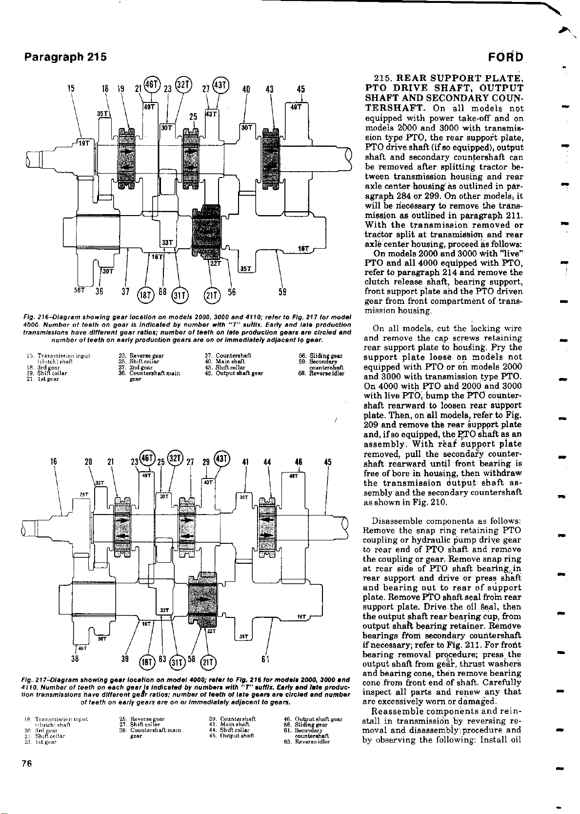
Paragraph 215
Fig. 216-Diagram showing gear location
4000.Number
transmissions have different gear ratios
15. Transmission input
Iclutch)sheft
l8. 3rd gear
19. Shift collar
21, fat gear
of teeth on gear is indicated by number with "T" suffix
number of
on early production gears
teeth
23. Reverseggear
25. Shifcollar
27. 2nd gear
38. Countershaft main
Per
16 26 21 23gO1 25 4L 21 29 "" 41 44 46 45
on models 2000,3060
;
number
of teeth
are on
37. Countershaft
40. Main ,haft
43. Shift collar
45. Output shaft gear
40 43 45 PTO DRIVE SHAFT
T
49
1 TERSHAFT. On all models not
56 59 front support plate and the PTO driven
and 4110
;
refer to Fig
.
on late production
or Immediately adjacent
Early and late production
gears
to gear.
56. Sliding gear
59. Secondary
68. Reverse idler
217 for model
.
are circled and
countershaft
gg1 I free of bore in housing
FORb
215. REAR SUPPORT PLATE,
, OUTPUT
SHAFT AND
equipped with power take-off and on
models 2000 and 3000 with transmission typo PTO, the rear support- plate,
PTO drive shaft (if so equipped), output
shaft and secondary countershaft can
be removed after splitting tractor between transmission housing and rear
axle center
agraph 284 or 299. On other models, it
will be necessary to remove the trans-
mission as outlined in paragraph 211.
With the transmission removed or
tractor split
axle center housing,proceed as follows:
On models 2000 and 3000 with "live"
PTO and all 4000 equipped with PTO,
refer to paragraph 214 and remove the
clutch release shaft, bearing support,
gear from front compartment of transmission housing.
On all models
and remove
rear support plate to housing
support plate loose on models not
equipped
and 3000 with transmission
On 4000 with PTO and 2000
with live PTO' bump the PTO countershaft rearward to loosen rear support
plate
Then
.
209 and remove the rear suppprt plate
and, if so equipped
assembly. With reaf` support plate
removed, pull the seconda'r`y countershaft rearward
the transmission output- shaft assembly and the secondary countershaft
as shown in Fig. 210.
SECONDARY COUN-
housing
at transmission and rear
the cap screws retaining
with PTO
on all models
,
as outlined in par-
, cut the locking wire
or on models 2000
, the 70 shaft as an
until front bearing is
, then withdraw
. Pry the
type PTO.
and 3000
. refer to Fig.
,
Fig.
217-Diagram
4110.Number of
tion
transmissions have
15. Transmission input
wh,mhl shall
20. 3rd ge
21. Shift collar
23. 1,tgear
76
showing gear
teeth on eachgear Is indicated by numbers with "T" suffix
of teeth on early gears are
location
different geltr ratios
25. Reversegear
27. Shift collar
38 Countershaft main
gear
on model 4000;refer to Fig.216 for models
;
number of teeth of late gears ere
on or
Immediately adjacent
39. Countershaft
41. Main shaft
44. Shiftcollar
45. outputahaft
61
2000, 3000
.
Early and Into produc-
circled and number
to gears.
46. Outputahaf gear
58.Slidin gear
61. Seconder
countershaft
Reverseidler
68.
Disassemble components as follows:
Remove the snap ring retaining PTO
coupling or hydraulic pump drive gear
to rear end of PTO shaft and remove
the coupling
or gear
at rear side of PTO shaft bearing-in
rear support and drive or press shaft
and bearing out to rear of support
plate. Remove PTO shaft
support plate. Drive the oil @eal, then
the output
output shalt
bearings
shaft rear bearing cup, from
bearing retainer
from secondary
if necessary;refer to Fig
bearing removal procedure; press, the
output shaft from
and bearing cone, than remove bearing
and
cone from front end of shaft. Carefully
inspect all
parts and renew any that
are excessively worn or damaged:
Reassemble components and reinstall in transmission by reversing removal and disassembly. procedure and
by observing the following: Install oil
. Remove snap ring
seal from rear
countershaft
. 211. For front
gear
, thrust washers
.
Remove
Page 75

3000-4000
-
2000
seals with lips to inside of transmission
(forward). Be sure that the high-low
coupling is engaged on teeth, on rear
end of mainshaft and that snap ring is
in groove in lower bearing bore of
transmission housing; refer to Fig. 212.
Place the secondary countershaft and
the output shaft assembly into rear
compartment of transmission as shown
in Fig. 210. Then, align front bearing of
secondary countershaft with bore in
housing and bump the shaft and
bearing assembly forward until front
bearing seats against snap ring. Install
rear support plate with new gasket, but
without output shaft bearing retainer
or PTO shaft. Tighten rear support
plate retaining cap screws to a torque
of 24-30 Ft.-Lbs. Insert PTO shaft and
bearing into rear of transmission, place
PtO gear in front compartment and
slide the shaft through the gear. Bump
the shaft forward until thrust washer
and snap ring can be installed on shaft
at front side of gear and snap ring can
be installed in rear support plate at
rear side of the PTO shaft bearing. In-
stall the front PTO shaft bearing, front
support plate, bearing support and
clutch release shaft as outlined in para-
graph 214. Install the transmission
output shaft bearing retainer with at
least 0.060 thickness of shims between
retainer and rear support plate and
tighten retaining cap screws to a
torque of 24-30 Ft.-Lbs. Measure
output shaft end float with dial indi-
cator as shown in Fig. 213, then re-
move the retainer and remove shim
thickness equal to shaft end float plus
an additional zero to 0,002 thickness to
provide proper bearing preload. Rein-
stall retainer and tighten cap screws to
a torque of 24-30 Ft.-Lbs. Shims are
available in thicknesses of 0.003, 0.005
and 0.012. Install locking wire through
rear support retaining cap screw heads
and reinstall PTO coupling or hydraulic pump drive gear.
216. MAINSHAFT ASSEMBLY.
To remove the mainshaft assembly,
first remove transmission from tractor
and remove front support plate, rear
support plate, input and output shafts
and the shift mechanism as outlined in
previous paragraphs, then proceed as
follows:
Remove the snap ring at front end of
transmission mainshaft and withdraw
the mainshaft from rear end of trans-
mission. Remove the gears, sliding
couplings, connectors and thrust
washers as the mainshaft is withdrawn. Remove ball bearing from rear
end of shaft. Remove bearing cup from
inside rear bore of shaft as shown in
Fig. 214. Carefully inspect all parts
and renew any excessively worn or
damaged parts. Bushings in inside
diameter of gears are not serviced separately; renew bushing and gear assembly if bushing is worn beyond further use.
Reinstall mainshaft assembly by
reversing removal procedure. For reas-
sembly guides, refer to Figs. 207 and
216 for models 2000 and 3000 and to
Figs. 208 and 217 for model 4000.
217. REVERSE IDLER. With the
--transmission mainshaft assembly removed as outlined in paragraph 216,
proceed as follows:
Refer to Fig. 215 and remove reverse
idler shaft retaining cap screw from
outside of transmission housing. Push
the reverse idler shaft forward and
remove the 4th-8th shift fork. The 4th8th coupling-gear can now be removed
from rear end of main countershaft.
Paragraphs
Push the idler
housing and remove the reverse idler
gear.
To reinstall
follows: Place reverse idler gear in
housing with long hub of gear forward
and insert idler shaft through housing
and gear with small diameter of shaft
to rear
pling
with shifter fork groove to front and
insert shifter fork in groove of coupling. Slide the idler shaft forward far
enough to install fork, then slide shaft
back through fork and install the re-
taining cap screw
coated
screw to a torque of 15-18 Ft.-Lbs.
With the transmission mainshaft removed as outlined in paragraph 216
and the reverse idler removed as in
paragraph 217, proceed as follows:
ondary countershaft front bearing bore
and the snap ring from bore at rear side
of main countershaft rear bearing.
Then, using suitable drift, drive the
main countershaft rearward until both
the front and rear bearings are free
from their bores and the assembly is
resting in bottom of transmission
housing. Place suitable wood or soft
metal blocks between the cluster gear
and rear supporting wall of transmission main compartment, then continue
to drive countershaft rearward forcing
the cluster gear and front bearing from
shaft. Remove the shaft from rear of
transmission and remove the cluster
gear and bearing from main compartment.
verse the removal procedure.
Place the
.
on teeth of
sealing washer
218. MAIN COUNTERSHAFT.
Remove the snap ring from sec-
To reinstall main countershaft, re-
shaft rearward out of
reverse idler
4th-8th
main countershaft
with a new rubber
216-219
proceed as
,
sliding cou-
. Tighten the cap
-
"SELECT
The "Select-O-Speed" transmission Is a
planetary gear drive unit providing ten
forward and two reverse speeds. Desired
gear ratio Is selected by moving a control
lever and starting, stopping or changing
gear ratios Is accomplished without operation of q conventional clutch. Afoot opera
ated feathering valve Is provided for Inter-
rupting. the gear train
gency or for close maneuvering such as
the hitching or unhitching of implements.
On models 2000, 3000 and 4000, the
In case
O-SPEED
of enter-
" (
10-SPEED
(All Models)
"Select
-O-Speed"
able with three
without a PTO,
RPM PTO or with a two
RPM PTO which
ground drive speed PTO.
Fora better understanding of the opera-
tion of the
,
alon, fundamental operating principles of
a planetary gear system are outlined In
following paragraphs 219 through 226.
transmission Is avail-
PTO options;
with a singlespeed 540
also Incorporates a
Select-O-Speed" transmis-
"
It Is available
speed
)
540-1000
TRANSMISSION
PLANETARY GEAR POWER
FLOW
All Models
219. Refer to Fig. 218; the three "elements" of a planetary system are the
sun gear, pinion carrier and the ring
gear. When any element is rotated, the
other two elements will also turn un-
less one is
Depending upon which element is held,
power can be applied or taken out at
held by an external force.
77
Page 76

2000
3000-4000
-
On models 2000 and 3000, a fourth
"D" (rear) planetary system is used as a
final reduction unit only. Power enters
at the "D" sun gear, the "D" ring gear
is held stationary and power is taken
from the "D" carrier which is integral
with the transmission output shaft.
Six basic speed ratios, five forward
and one reverse, are obtained by various combinations of holding or
applying power to the elements of the
"B" and "C" planetary units. The "A"
(front) planetary unit is used as a direct drive-overdrive unit to double the
basic speed ratios providing ten forward and two reverse speeds.
228. PLANETARY CONTROLLING UNITS. Three brake bands and
four multiple disc clutches are used to
control the "A", and "B", and "C" planetary units to provide the different
speed ratios.
The three brake bands are designated, from front to rear, as Band 1,
Band 2 and Band 3. The bands are actuated by hydraulic servos designated
Servo 1, Servo 2 and Servo 3 to correspond with the band numbers. The
servos contain springs that work in the
opposite direction from hydraulic pressure. The servos apply the bands with
spring pressure and release the bands
utilizing hydraulic pressure. The
bands, when applied, hold planetary
elements stationary as follows:
Band Planetary
Applied Element Held
Band 1 "A" Sun Gear
Band 2 "B" Ring Gear
and "C" Sun-Gear
Band 3
"C" Carrier
TIMING VALVE
SERVO 3
VALVE
VALVE
SERVO
SERVO 2
TIRING
VALVE
SERVO 2
Fig. 220-Schematic diagram of Select
diagram
showing operation of feathering
------- - - --------
TRANSMPS5101
FEATHERING
SEAULNCING
OFF
RESTRICTOR
j \
BANG 3
9
PT.O. CLUTCH CLUTCH I CLUTCH 2
0
FLATHERING
EGULATIMC VALY
7M
0-Speed transmission
-
the servo
and to
valve
2 and 3 timing valves.
FEATHERED
TO GI
VALVE
SYSTEM-
RESTRiCTOR
in
EACMAMGIM
TRANSMISSION LUBRICATION
El [I
hydraulic
Figs.
222
and
Paragraph 228
LUT
P
G G E
'TRANSMISSION
HEAT I
SUMP
223
❑❑
El
system.Refer to
for
operating principles of
ON
RESTRICTOR
DIRECT GUY
CLUTCH
RELIEF VALVE
221 for
Fig
.
CI
The multiple disc clutch packs are
designated, from front to rear, as the
Direct Drive Clutch, Clutch 1, Clutch 2
and Clutch 3. (Clutch 2 and Clutch 3
are contained in the same housing.)
The clutches are engaged by hydraulic
pressure against a piston within the
clutch unit and are disengaged by
spring pressure returning the piston to
disengaged position. The clutches,
when engaged, lock planetary elements together as follows:
Clutch Planetary
Engaged Elements Locked
Direct Drive "A" Sun Gear
to "A" Carrier
Clutch 1 "B" Carrier to
"B" Ring Gear
Clutch 2 "B" Carrier to
"C" Carrier
Clutch 3 "B" Carrier to
"D" Sun Gear (2000
& 3000) or to Out-
put Shaft (4000)
Fig. 221-Cross-
sectional
views showing
"OFF", "FEATHERED"
transmission
and "ON
and PTO feathering
"
positions.
valve
assemblies
In
79
Page 77

Paragraph 229
Fig.
VALVE ASSEMBLY valve
of Servo 2,
time whenhydraulicpressure
servo is shown
sequence
for valve
time
sure is being released.
222-Cross-
.
is being applied to
servo
Valve
views In Fig.
positions
hydraulic
section
Servo 3 timing
position
.
Refer to
view
during
223
during
pres-
FORD
as
"SELECT-
O-SPEED"
HYDRAULIC SYSTEM
All Models
229. HYDRAULIC CIRCUITS.
Refer to Fig. 220 for diagram of the
Selec!.-O-Speed" hydraulic circuits.
Pressure is supplied directly to the
Band 1, Band 2 and Band 3 control
valves and PTO feathering valve (direct transmission circuit); indirectly to
the Clutch 1, Clutch 2 and Clutch 3
control valves via the transmission
sequencing valve and the transmission
feathering valve (indirect transmission
circuit) and indirectly to the transmission cooling and lubrication circuit via
the transmission regulating valve.
Refer to Fig. 221 for diagrams
showing operation of the transmission
and PTO feathering valves. With the
inching pedal (transmission feathering
valve control pedal) up or the PTO con-
trol handle pulled out, pressure is di-
rected to the indirect transmission cir-
cuit or to the PTO clutch. With the
inching pedal fully depressed or the
PTO control handle pushed in, the
feathering valves block pressure from
the indirect transmission circuit or
from the PTO clutch. With the inching
pedal partially depressed or the PTO
control handle partly pulled out, pres-
sure in the indirect transmission cir-
cuit or PTO clutch can be "feathered"
to provide smooth starting of tractor or
smooth engagement of the PTO clutch.
This is similar to slipping a conven-
tional clutch and the transmission or
PTO clutch should not be operated for
any period of time with the control in
"feathering" position.
The transmission sequencing valve
separates the direct and indirect hydraulic circuits so that oil is supplied
only to the direct circuit when system
oil pressure drops below valve setting
of 125 psi. This prevents Bands 2 and 3
from locking up the transmission when
!arge quantities of oil are required such
as during the 4-5 and 5-4 shifts.
The system
trols pressure within the transmission
hydraulic system to 200-210 psi (at 800
regulating
valve con-
engine RPM and oil temperature of 80120°F.). When pressure in system exceeds the regulating valve pressure
setting, the valve opens and oil passes
into the transmission cooling (on some
models) and lubrication circuit. When
system pressure is below regulating
valve setting, oil pressure in lubrication circuit drops to zero and the oil
pressure warning light will come on.
Note: warning light circuit was discontinued in March 1968.
The transmission relief valve limits
maximum pressure in the hydraulic
system to 220-230 psi on models with
oil cooling system (heat exchanger) and
to 210-220 psi on models without heat
exchanger. Oil by-passing the relief
valve is returned to the sump via the
return tube attached to control valve
assembly.
Timing valves are incorporated in
the Servo 2 and Servo 3 circuits to
permit gradual application of bands
and to prevent both Band 2 and Band 3
from being engaged at the same time
during the 4-5 and 5-4 shifts. During
these shifts, one servo is pressurized to
release its corresponding band and
pressure is released from other servo to
apply its corresponding band. Oil flow
to the servo (See Fig. 222) to release
the band is not restricted as the valve
assembly return spring will be compressed and oil will by-pass the valve.
On the other servo return oil will first
compress the valve body return spring
(Step 1-Fig. 223) and oil will flow
through both the valve orifice and the
four annular ports. As servo oil pres-
sure begins to drop, the valve body return spring expands moving the valve
to close off the four annular ports (Step
2) which slows down the flow of oil from
servo and allows band to gradually
apply. When servo pressure drops further, the valve body spring expands to
full length again opening the four annular ports (Step 3) to provide a final
dumping of oil to permit the band to be
completely applied.
When the Band 1-Direct Drive
Clutch spool in control valve assembly
is closed to pressurize the circuit, oil
OIL FROM SERVO
Fig.
223-Sequence
timing
sure is
sure Is
allows afeet
begin
creases,timing valve spring
permit a relatively slow continued
sure drop as
band
sure has decreased
valve spring
dumping of oil
pletely applying the band by servo
during
valve
being released
applying band
Initial
application
band
shown in
application.In view 3,
to move
from servo
ofServo 2-Servo 3
views
time servo
,
In view t, valve
.
pressure
.
view 2
for
sure.
hydraulic pres-
and servo
drop in
As servo pressure de-
moves
permit gradual
to
hydraulic pres-
servo
enough to
valve
so
can take place, com-
pressure will apply the Direct Drive
Clutch as the Servo 1 spring is compressed to release Band 1. Conversely,
as the spool is opened to release circuit
pressure, the spring in Servo 1 will
apply Band 1 as the Direct Drive
Clutch is released.
spring pres-
position
servo to
valve
some pres.
allow timing
that a final
spring pres-
0
Me
We
to
M
80
Page 78

2000
-
POSITION
OR SEAR
PARK (P)
NEUTRAA (N)
3000-4000
DIRECT
DRIVE
CLUTCH
A A
A A
Paragraphs
230. CONTROL POSITIONS
(GEAR SELECTION). Fourteen control positions are provided on the gear
selector. Units of the transmission that
are applied in each position of the gear
selector are shown in the Application of
Bands and Clutches Chart (Fig. 224).
LUBRICATION AND FILTERS
All Models
231. As the Select-O-Speed transmission incorporates a hydraulic control
system, use of correct lubricating oil
and keeping the oil clean is of utmost
importance.
Recommended fluid is Ford Specification No. M2C41-A transmission and
hydraulic oil. Capacity is 13'4 quarts
for model 4000 and model 3000 with
heat exchanger, 12 quarts for models
2000 and 3000 without heat exchanger.
Fluid should be maintained to bottom
of oil level plug (See Fig. 225). Add oil
through oil level plug openings.
To remove the pump intake screen,
first drain oil from transmission, then
remove filter screen as shown in Fig.
226.
The pleated paper filter element
should be renewed each 600 hours of
service and the fluid changed every
2400 hours to coincide with each 4th oil
filter change. To remove old filter,
unbolt the filter cover (Fig. 227) and
unscrew filter from cover. When reinstalling filter cover, tighten retaining
bolts to torque of 35-40 Ft.-Lbs.
230-231
IRTN
224-Chart showing transmission
Fig.
plied by
hydraulic
servo
pressure
spring
and are
A
pressure and are released
released
units appliedateach gear
by spring pressure. Hydraulic pressure Is Indicated by shaded
by hydraulic
area.
selector
pressure
position.
. Clutches
Bands are ap-
are applied by
SYSTEM ADJUSTMENTS
All Models
Malfunction of the "Select-O-Speed"
transmission could be from a number of
causes, the most common of which is
maladjustment of one or more units of
the transmission. Therefore, the first
step in correcting troubles would be a
ILTER ADAPTER PLATE
.is
ILTER SCREEl
3000 and 4000
Fig. 225
-
oil level-filler plug
View showing
on
4000
location
models
.
oftransmission
3000
2000
,
and screen being removed
Fig. 226
showing transmission
-
View
and
4000 transmission
f
rom model 2000
.
pump filter
,
3000
Fig. 227-Removing model 2000
Select-O-Speed transmission
and adapter plate
(
from
cover
).
cover.
Unscrew
,
oil filter element
element
81
Page 79

Paragraphs
232-235
FORD
YORAUPC urn
Fig. 228-View
(shaft)
lever
on
showing location of drive line
disengagement lever on mode14000;
models 2000
and
tion.
3000 Is
comaCt rives
In similar
Paragraphs 238-240
Fig.
237-PTO handle housing (
instrument
and "B' indicate
panelbynut (
adjustment
refer
N) and spacer
to text.
H) is retained to
measurements;
loca-
(S). "A"
'.#'..
Fig. 231-View
method ofattaching trans.
mission oil
cooler tubes to
transmission housing.
I Inlet tube
IA. Inlet tube (4200)
2. Outlet tube
2A. Outlet tube (4200)
3. Adapter bolts
4. Unions
position, the first step is to disengage
the ra
ioncnnnlinusa
Pull control handle out and discon-
nect the control cable conduit at both
ends. Remove nut (N), lockwasher and
spacer (S) from slider housing and pull
the handle and slider housing out of
hood opening. If there is no clearance
between ends of conduit and fittings
with handle pulled out, turn handle
and slider housing (H) clockwise until
there is clearance; then, be sure handle
is fully out and turn handle and slider
housing counter-clockwise until ends of
conduit just contact fittings. Turn
handle and slider slightly farther
counter-clockwise, if necessary, so that
word "PTO" is in vertical position.
Reinstall slider housing and reconnect
cable conduit. Recheck control handle
movement and readjust if necessary.
240. ADJUST PTO INTERLOCK.
On models with 2-speed PTO, an interlock mechanism is necessary to prevent
showing
f
ollows-
3
If pressure gage reading
running at 800 RPM was in the speci-
EXTERNAL HELPER
RETURN SPRING
Fig. 239-On model 4200,inching pedal rod
be adjusted
foot pedal arm and platform
to obtain
a 0.010-0.060 gap between
with engine
FORD
at point shown.
must
a_
iL
MIL
C-
s
W
Fig.
238-View showing
move lever back to left
PTO interlock
linkage.
side if desired
and reinstall shaft end cover.
278. SELECTOR
TION,
LEVER STOPS AND NEU-
LEVER POSI-
TRAL BY-PASS PLATE. The
selector lever is normally placed on
right side of selector housing for right
,
hand operation
;
however
if operator
prefers, lever can be installed on left
side as shown in Fig. 236,
Stop screws can be placed at R2 or RI
and 3rd, 5th
desired. When
or 7th
shift positions if
not in use
the stop
,
screws are installed on opposite side of
housing
from shift
A neutral by-
lever position.
pass plate can be in-
stalled over the neutral notch in
GEAR
RATIO
PARK
R2
R1
NEUTRAL
1st
2nd
3rd
4th
5th
6th
7th
DIRECT DRIVE
CLUTCH
Ali
Rh
P
P
RI
R2
R1
P
N
P
P
1
2
P
1
3
2
4
P
5
6
P
7
Am
R1
BAND1BAND
Rm
A
R
P
N
R1
N N
P
L
L
R2
P
P
R2
L
N
L
N
L
L
N
BAND
2
R
A
N
P
R2
92
R1
R1
N
N
CLUTCH1CLUTCH
3
A
R
N
L
N
R2
N R1
N
A
R
L
P
L
N
N
L
N
N
N
CLUTCH
2
R2
R1
3
A
L
L R2
L
R1
N
R
P
na
N
R
P
N
a
L
N
L
N
N L
3
4
N
N
7
L
3
4
L
L
7
2
N
N
5 5
66TN
N
1
2
L
L
5
6
L
1
1 1
L
L
2
L
3 3
L
4
N
N
2
N
N
4
L
5
L 6
N
7
7
L
1
L
2
L
3
L
4
L
5
L
6
L
7
1
N L
2
L
3
N
4
L 5 5
N
6
L
7
N
1
2
N
3
L
4
N
6
L
N
7
M
Page 80

2000
3000-4000
-
Paragraphs
241-244
possibility of both the engine drive and
ground drive PTO from being engaged
at the same time. To check interlock
adjustment, proceed as follows:
With engine not running, push engine drive PTO control knob in and
move ground drive PTO lever to "ON"
position; it then should not be possible
to pull the engine drive PTO control
knob out. Move the ground drive PTO
lever to "OFF" position and pull engine
drive PTO control knob out; it then
should not be possible to move the
ground drive PTO lever to "ON" posi-
tion. If both controls can be engaged at
the same time, or if neither can be fully
engaged even though the other is disengaged, remove top cover from trans-
mission as outlined in paragraph 247,
refer to Fig. 238 and proceed as follows:
NOTE: Transmission control valve
must be installed to adjust PTO interlock although it is not shown installed
in Fig. 238.
Loosen lock nut and set screw in
cable clamp and move ground drive
PTO lever to "ON" position. Then, retighten set screw to clamp cable so that
when pulling up on the control cable
slider, a 0.005-0.015 clearance remains
between end of PTO feathering valve
and the cam on feathering valve lever.
When adjustment is correct, tighten
the lock nut and reinstall transmission
top cover. Be sure the engine drive
PTO control is properly adjusted as
outlined in paragraph 239.
241. ADJUST INCHING PEDAL
(Model 4200 Only). Refer to Fig. 239;
the length of the inching pedal rod as-
sembly must be adjusted to give a
0.010-0.060 gap between the pedal return stop and the pedal shank. Incorrect adjustment may prevent full
closing of the transmission feathering
valve, thus result in improper operation and/or damage to transmission
components.
TROUBLE SHOOTING
All Models
242. OPERATIONAL (MECHANICAL) CHECK. If the system adjustments outlined in previous section fail
to correct transmission malfunction,
the next step in trouble diagnosis
would be an operational check. To perform this check, proceed as follows:
Place traction coupling in engaged
position, start engine and set engine
speed to 800 RPM and depress the
inching pedal. Shift the transmission
selector to each of the fourteen positions in turn starting with Park (P),
gradually release the inching pedal at
each position and record the reaction
when pedal is released. One of the five
following conditions will be encountered.
DIRECT CIRCUIT
GEAR
RATIO
RR
R
NEUTRAL
D.D.C.
P
p
P
2nd
3rd
4th
th
5
Fig. 241-Hydraulic trouble
"P" Indicates hydraulip
p
orts.
P
P
Refer to text
B1
P
p
P
P
P
shooting chart for use
pressure
for hydraulic circuit
(1) The transmission will operate
properly for the control position
selected.
(2) The transmission will operate in a
different speed ratio than that selected.
(3) The transmission will go into a
"neutral" condition in control position other than neutral.
(4) The transmission will go into park
condition in control position other
than park.
(5) The transmission will lock up and
stall the engine.
If transmission seems to operate
properly in all fourteen control positions, proceed with TORQUE LIMITING CLUTCH CHECK as in paragraph 243, then the HYDRAULIC
CIRCUIT CHECKS as outlined in paragraph 244. If any of the malfunction
conditions (2), (3), (4), or (5) are encountered, compare the recorded reactions for each of the control positions
with the columns in the operational
trouble shooting chart in Fig. 240. The
matching column in the trouble
shooting chart will indicate the malfunctioning unit and whether the
trouble is caused by the unit being continually applied ("A" column) or released ("R" column).
243. TORQUE LIMITING
CLUTCH CHECK. A defective or
worn torque limiting clutch should be
suspected if transmission malfunction
exists only under heavy loads and in
the higher speed ratios, especially if
the transmission operates properly in
B2 B3
P
P P
P
P
P
P
P
P
It
gage installed at one or more servo pressure
with
for different
to unit
applied
shooting procedure.
trouble
-
the lower speed
To check the torque limiting clutch,
operate the tractor in 8th, 9th or 10th
speed position at wide open throttle
and quickly apply both brakes. If
tractor forward motion can be halted
without pulling the engine down below
1000 RPM or without stalling the en-
gine, renew torque limiting clutch as
outlined in paragraph 253.
244. HYDRAULIC CIRCUIT
CHECKS. Leakage in any of the hydraulic circuits to servos or clutches
can be detected by performing the following pressure checks.
With a 0.300 psi hydraulic
stalled at Servo
or 230),
ture at 80-120° F., traction coupling
disconnected as outlined in paragraph
232 and with engine running at 800
RPM, record hydraulic
each selector position shown in the
hydraulic trouble shooting chart in
Fig. 241 except 5th gear. Normal gage
reading for each position is 200-210 psi
with a maximum variation of 3 psi. A
leak in any one circuit will show up as
one of the following conditions; leakage
in more than one circuit will show up
as a combination of conditions:
A. Low Gage
Positions
tion (Fig. 229 or 230) and observe pressure gage reading with selector at 5th
gear. A normal gage reading (200-210
psi) would indicate leakage in Servo 2
circuit; a continued low reading would
indicate incorrectly adjusted
INDIRECT CIRCUIT
C1
C2
P
P
P
selector positions.
ratio
gear
ranges.
2 location (
transmission
-Move gage to Servo 3 loca-
see Fig. 229
fluid tempera-
gage reading at
Reading In All
C3
p
P
P
gage
transmis-
in-
85
Page 81

Paragraphs 245-246
FORD
nocf }ti^osed_cantraLcable at lower
Paragraph
Fig. 249-Presscable wheel and trunnion Into
camshaft so there
cable
wheel
supporting opposite
half
252 Cont.
Is 0.010clearance
and upper
valve body.Note
end of camshaft.
between
ibinch
assembly in Fig. 247 and proceed as follows:
NOTE:
There are some differences between the valve assembly used In model
4000 beginning with September 1968 pro-
duction and the assembly used In other
models;notably,the late 4000 servo and
clutch valves do not have return springs,
but are returned by the rocker arms which
lit in notches in outer ends of valve
spools.However,service procedures and
specifications remain essentially the
same for all units with any differences
noted in the following text:
Remove the two cap screws that hold
the halves of control valve assembly
together, then separate valve body half
(22) from camshaft body half (3). The
six control valve spools (26A or 26B)
can now he removed. On all models
except late 4000, remove the control
valve spool return springs (31). Re-
move the feathering valve retaining
plate (34) and withdraw the feathering
valve plungers (32 and 33), springs (29
and 30) and feathering valves (27 and
28). NOTE: On models without PTO, a
valve spool (26) (same as 26B) is substituted for the PTO feathering valve
(28), spring (30) and plunger (33) as
these parts are not required. The retainer plate (23) can now be removed
from valve body half (22) for better access to clean spool bores. Remove the
adjusting screw retainers (18 and 19),
adjusting screws (17), springs (14, 15
and 16) and valves (13 and 13A) from
camshaft body half (3).
Check the cam followers (rocker
arms) (11 or IIA and 113) and shaft
(101 for wear or damage; to disassem-
and
shift
from
or vice
and detent
Installed in place
Fig. 251-Exploded view of
lower valve body and
ering valve assemblies. Note
that PTO plunger(33)
two Identification
outer end and PTO feathering valve(29) has
land
sion
PTO feathering
Is shorter than transmission
feathering valve
follower (
Park
versa.New camshaft
plunger can be
type.
than does the transmis-
feathering
8) and
gear
to 10th
of previous
feath-
has
grooves In
shorter
valve (41).
valve spring
spring (38).
spring (9) and the cam-
PREVIOUS TYPE
New type camshaft
Fig. 250
-
defeat prevents over-
shaft cable wheel (7) for wear or
damage
To disassemble
.
, thread a Y4inch diameter, 20 thread, 3 inch long
socket head screw (or other hardened
V4-inch x 20 bolt with at least 1%
steel
inches threaded) into the cable wheel
(7), hold camshaft with wrench and
turn the screw to force cable wheel and
trunnion assembly from camshaft.
Remove trunnion (6) from opposite end
of camshaft using same screw. Note:
Do not
use a common steel or rethreaded bolt for a forcing screw; this
type of bolt or screw will twist off in
cable wheel or trunnion. The camshaft,
detent plunger and spring can now be
removed.
Carefully clean all parts in solvent,
air dry and check against the following
values:
Control Valve Spool Diameter
Late Model 4000 .... 0.3743-0.3747
All Other Models .... 0.3738-0.3742
Feathering Valve Spool Diameter,
All ................ 0.3743-0.3747
Valve Bore Diameter,
All ................ 0.3751-0.3758
Spring Free Lengths:
Camshaft Detent Plunger ..... 0.75
Control Spool Return ......... 1.24
FORD
NEW TYPE
Transmission Feathering Valve:
Return ...................... 1.22
Plunger ..................... 1.40
PTO Feathering Valve Return .. 1.22
Plunger ..................... 1.12
To reassemble, proceed as follows:
Lubricate all parts prior to assembly.
Insert detent spring (9) and detent follower (8) in bore of body half (3) and
position camshaft (5) so that detent
cam is aligned with detent; hold camshaft in place with a %-inch bolt inserted in trunnion (6) end of shaft.
Note: The bolt must be long enough to
bottom in shaft. Place unit in arbor
press as shown in Fig. 249 and press
cable wheel into camshaft so there is
0.010 clearance between wheel and
valve body. Thread the forcing screw
that was used in disassembly into the
cable wheel until bottomed; then turn
unit over in arbor press and press trunnion (6-Fig. 247), chamfered end first,
into camshaft until flush with valve
body camshaft support boss.
On late model 4000, insert the shaft
(10) through hole in boss of body (3)
and install the cam followers (11A and
11B) on shaft as it is pushed into place.
Note: Follower (11B) on cable wheel
end is constructed with cam arms
placed opposite the cam arms of the
r.
a
Page 82

2000
3000-4000
-
Paragraph 253
On models other than late 4000, use
Fig. 247 as a guide to install shaft (10),
cam followers (11) and spacers (11C,
11D and 11E), noting the following:
Install followers on shaft with short
rounded end seated against cams.
Spacers (11C) are 0.058 thick; spacers
(11D) are 0.348 thick and spacer (11E)
is 0.878 thick. Secure shaft with snap
rings (12) inserted in grooves on shaft.
Insert the valves (13 and 13A-Fig.
247) (all three valves are alike) into
bores of body (
3). Insert spring (14)
(2.89 inches long) in bore farthest from
cable wheel end. Insert spring (15)
(2.06 inches
wheel end and
long) in bore nearest cable
insert spring
(16) (2.47
inches long) in middle bore. Thread the
adjusting screws (17) (all screws alike)
in flush with valve body. Do not install
retainers (18 and 19) until valve has
been adjusted as outlined in paragraph
235.
Install retaining plate (23) on valve
body (22). On models with PTO, install
(38) in grooves of
the two snap
rings
the feathering valve plungers (32 and
33), insert the valves through the return springs (37) and plate (35). Compress return springs and install
notched plate (34) over valve plungers.
Insert PTO feathering valve (28) (valve
with narrow land at hollow outer end)
into bore towards end of valve body
having four control valve bores and the
transmission feathering valve (27)
(valve with wide land at hollow outer
end) into bore towards end of body
having two control valve
spool bores.
Insert the PTO plunger spring (30)
(1.12 inches long) in hollow end of
valve (28) and transmission plunger
spring (29) (1.140 inches long) in
hollow end of valve (27). Install the
assembled valve plunger, spring and
plate assembly so that plunger (33)
with identification groove in outer end
is in the PTO valve spool bore (towards
end of valve body having four control
valve spool bores) and secure with
screws.
On models without PTO, install the
transmission feathering valve as outlined in preceding paragraph; however,
valve spool (26) is installed in place of
PTO valve (28), spring (30), plunger
(33), return spring (37) and snap ring
(38).
On all models except late 4000, drop
the six spool return springs (31) in the
control valve bores.
Lubricate the control valve spools
(26A or 26B) and carefully insert them
in their bores with a twisting motion to
avoid scraping bores with sharp edges
of valve lands. On late model 4000,
turn the valve spools so that notches in
outer ends of spools are positioned as
shown in Fig. 247. On late model 4000,
Fig.
252-Exploded view
assembly
clutch
tional view showing proper Installation
Fig.
ment
Fig.
assembly.
tion as
and seal
1. Cover
3. Rotor
Belleville
1. Clutch housing
2. Spring
3. Pressure plate
253-Cross
of Belleville spring washer
(6); refer to
254-Exploded
Fig
Unit can be disassembled for inspec-
shown; however,
(for models 2000, 3000 & 4000) are
(6)
available for
of typical torque limiting
Refer
.
-
sectional
Fig.
to
spring) washer (2).
(
view
252 for
.
parts identification
of transmission
view
only
service.
253 for cross-sec-
4. Clutch disc
5. Facings
showing
(
2). Flywheel is
the
of the
place
pump
"0" ring (2)
4. Roller.
or Plug
I se.
I
place the two valve body halves to-
gether so that ends of followers engage
notches in valve spools; or, on other
models, place valve body halves together so that ends of followers contact
ends of valve spools. Install the two cap
screws that hold the body halves together and tighten the cap screws to a
torque of 6-8 Ft.-Lbs. Refer to paragraph 235 for adjustment of the trans-
mission regulating and relief valves,
then install the adjusting screw retainers (18 and 19).
253. TORQUE LIMITING
CLUTCH. To remove the torque lim-
iting clutch, first split tractor between
engine and transmission as outlined in
paragraph 181 or 182. Then, unbolt
and remove the clutch assembly from
flywheel. Refer to Fig. 252 for exploded
view of the clutch assembly.
Renew the clutch disc facings or the
clutch disc assembly if facings are
glazed, oil soaked or excessively worn.
Thickness of new disc with facings is
0.329-0.353 for all models. Note: Late
production clutch disc is spring loaded
instead of solid disc as shown in Fig.
252.
Renew the Belleville (spring) washer
if discolored, cracked, or if it fails to
meet the following specifications:
Color
Code
Red
Yellow
-
.
Tractor
Model
2000
,3000
4000
Note. Free height is measured as dish
in the spring washer. Color code
inch wide paint mark on outer edge of
the spring washer.
Drive plate thickness on all models
should be 0.278-0,282. Renew drive
plate if cracked, scored, warped or excessively worn.
Check the splines in the clutch disc
hub and on the transmission input
shaft for rust or excessive wear. Renew
the clutch disc assembly if backlash of
disc on input shaft, measured at outer
diameter of disc, exceeds 'Fs-inch.
Renew the input shaft if backlash of
new disc on input shaft exceeds 1/4-inch.
Before reassembly, be sure splines on
input shaft and in clutch disc are clean
and free of rust; then, apply a thin film
of light silicone grease (Ford part No.
M1C-43) to splines of both parts.
When reassembling, be sure that the
concave side of the Belleville washer
(2) is towards the clutch cover (1) as
shown in Fig. 253. The clutch disc is
piloted in the flywheel, thus no
aligning pilot is required. Tighten the
clutch cover retaining cap screws to a
torque of 25-30 Ft.-Lbs.
Thick-
news
.106-0.109
0
0.106-0.109
Free
Height
0.175
0.189
is a ''/c-
89
Page 83

Paragraphs
IRA HUMS 5101
INPUT SHAFT
254-256
DIRECT DRIVE
CLUTCH
E, N SUN GEAR
UTCH
2000 3000
DISTRIBUTOR
4000
5000
EIALt..'.+:
NDICATOP
Fig. 256-View showing dial Indicator
"C" sun
gear
to check
play on models
transmission front end
2000, 3000
and
FORD
set against
4000.
"C" SUN GEAR
Fig. 255-Exploded
Washer between
frontend play. Washer
output shaft
view
of transmission
I assembly and Distributor
Clutch
between "D" Sun
and rear support (models 4000)
254. TRANSMISSION PUMP. To
remove the transmission pump, first
split tractor between engine and transmission as outlined in paragraph 181
or 182, then unbolt and remove the
pump assembly. Refer to Fig. 254 for
exploded view of pump. The transmission input shaft extends through and
drives the pump.
The transmission pump, except for
rear plate retaining screws, "0" ring
(2) and
seal (6
assembly only.
is serviced as a complete
)
Disassemble
clean and
,
inspect the pump paying particular
attention to the cam surface in pump
body (5). If cam surface is worn or pit-
ted, renew the pump assembly. If pump
is serviceable,
"0" ring and
reassemble using new
. Install seal with lip
seal
to inside using OTC step plate No. 6305 or equivalent.
Reinstall pump with new mounting
gasket. Be sure pump is correctly positioned and
install two retaining cap
screws opposite each other. Tighten
these screws to torque of 3-5 Ft.-Lbs.,
then install two remaining screws to
torque of 3-5 Ft.-Lbs. Final
cap screws alternately and evenly
four
to torque
of 15-18 Ft.-Lbs.
tighten all
255. TRANSMISSION END
PLAY.
Transmission end play is controlled by bronze thrust washers placed
between each of the rotating members.
Refer to Fig. 255
length
of the
Variation in total
.
transmission components
is compensated for during assembly by
providing two selective
ers, one at
the rear of
fit thrust wash-
each transmis-
V.
J
"
CLUTCH
2 ANDR
drive
components
Is
is
selective
of
selective
Gear and "D" Carrier (models
D" SUN GEAR
C" RING GEAR 2000
showing thrust
thickness
thickness to
sion section, to hold end play within
specified limits. Cumulative wear of
the thrust washers and of thrust surfaces on other parts will require that
the end play be checked at each overhaul, then renewing the selective fit
thrust washers with ones of greater
thickness to provide correction for
wear.
End play should be checked as out-
lined in paragraphs 256 and 257 before
disassembly
of the involved
sion components
dures outlined
based on the
supposition
selective fit thrust
only ones which will be renewed. However, if any other thrust
other transmission parts are renewed,
the difference in thickness of the new
parts will affect thickness of the selective fit washers to be installed. Thus, it
is important to check end play during
reassembly to be sure the proper thick-
ness of selective fit thrust washers
have been installed.
256. TRANSMISSION FRONT
END PLAY. To check transmission
front end play, all drive
rear of "C" sun gear and distributor
must first be removed and, if the trans-
mission has
not been removed from
tractor, the steering
front compartment cover plate must be
removed to
provide access
transmission components. Loosen
Band 1 and
Band 2 adjusting screws.
Then, mount dial indicator
rear end of "C" sun gear as shown in
Fig. 256. Pry "C" sun gear forward and
\ ' \ CARRIER
RING OEAIIQ
placement.
washer
to adjust
2000 & 3000)
adjust rear end play.
transmission
or between
transmis-
. The overhaul proce-
in this manual are
that the two
washers are the
washers or
components to
assembly or
gear
to the front
against
CREW DRIVER
RANSMISSION
OUTPUT SHAFT
DIAL INDICATOR
SUPPORT-TOOL
Fig. 257
transmission
rear and play on
Pry against
Model
however
View showing dial indicator
-
output shaft to
C" ring gear
"
obtain endplay reading.
Fig. 258-Removing
5000 Is shown
other models are similar
,
is located
at upper side of transmission housing.
models 2000
Servo I assembly
check transmission
,
as shown
for illustrative purposes;
3000 and 4000.
set dial indicator to zero while holding
slight pressure against the sun gear.
Refer to Fig. 255 and insert a screwdriver between the "B" carrier and "A"
ring gear and pry "B" carrier rearward.
The resulting dial indicator reading is
transmission front end play which
against
set
In Inset
and
cover.
except servo
to
90
Page 84

2000
Fig. 259
band 1
,
direct drive
gear
(
4. Servo spring
4. "0" ring
S. Servo piston
9. Piston rod
10. "0" ring
1I. Strut
3000-4000
-
View showing
-
adjusting
screw
clutch
placement
and
housing).
13. Bend1
14
39.
Servo 1,
of
strut to "A" sun
Adjusting screw
.
A'sungearDirect Drive
Clutch housing
262-Rembying Servo 2-3
Fig.
cover
housing
tubes
tributor
transmission
from
.
Inset shows
being pulled
permit removal of
to
the distributor.
from
servo
dis-
Paragraphs
257-259
we
Fig.
260-Exploded
N. Nut
W. Washer
1. Cover
2. Gasket
3. RatainSr
4. Spring
Fig. 261-Compressing
press to remove
draulic
view of Servo I
servo
nut and
piston rod.
assembly.
5. Snap ring
7. "0" ring
8. Piston
9. Piston rod
10. "0., ring
11. Strut
assembly in hy-
washer
should be 0.005 to 0.015. Record the
end play measurement for reassembly.
Front end play is adjusted by selecting,the,proper thickness of thrust
washer to be installed between the distributor and clutch 1; refer to Fig. 255.
This thrust washer is available in
thickness of 0.062 to 0.122 in steps of
0.010.
1257. TRANSMISSION REAR
END PLAY. Transmission rear end
play can be checked after splitting
tractor between transmission and the
rear axle center housing and removing
the top cover. To check rear end play,
proceed as follows:
i.oosen the Band 3 adjusting screw so
that the band is completely released.
Mount a dial
. indicator as shown in Fig.
257. Pugh in on the transmission
output shaft
while holding
and zero
pressure
pry between "C" carrier and "C" ring
gear with a screwdriver (see inset in
Fig: 257); the resulting dial indicator
reading will be. transmission
play which should be 0.005 to 0.015.
Transmission
rear end play' is ad-
justed by selecting the proper thickness
of thrust washer to be installed between the shoulder on transmission
output shaft. and rear support on
models 400,0, or between the 'D' sun
geat and "D" carrier on models 2000
and 3000. This washer is available in
thicknesses of 0.102 to 0.142 in steps of
0.010 fbr models 4000 and in thicknrisses of 0.092 to 0.132 in steps of
0.010, and also thickness of 0.140 and
0.150 for models 2000 and 3000.
268. SERVO
SERVO 1 ASSEMBLY. To remove
the Servo 1 Cover and Servo 1 assem-
bly, proceed
as follows:
While holding Band 1 adjusting
screw from turning, remove the ad-
from
justing screw locknut and flat washer.
the dial indicator
on shaft. Then
rear end
1 COVER AND
Then, slowly back adjusting screw out
until servo spring tension is relieved.
CAUTION: Do not back adjusting
screw out farther than necessary as
this will allow the Band 1 strut to fall
out of place making disassembly of
transmission necessary. Remove the
four cap screws retaining Servo 1
Cover to transmission and carefully
remove cover. Slowly turn adjusting
screw in, forcing servo assembly out,
until screw is,tight. Then, withdraw
servo assembly from transmission
housing. Refer to Fig. 258.
The servo sealing "0" rings (7 and 10
-Fig. 260) can now be renewed and
the servo assembly reinstalled. However, if inspection of unit reveals excessive wear or other defect, proceed as
follows to disassemble and overhaul
the servo:
NOTE: On early production units, Servo
1 piston rod pilot diameter was 0.730-
and piston outer diameter was
,
0.714
1.993
countered
proved by
piston
rod pilot diameter Is 0.734
piston outer diameter Is 1.981
larger rod pilot diameter and the smaller
piston diameter reduce the possibility of
piston cocking and wedging In bore of
transmission housing.
.
if these early parts are en-
1.997
-
servo operation can be Im-
,
renewing both the rod and
„
service and late production piston
;
0.736, and
-
-1.985. The
259. To disassemble the servo, place
the assembly in a press using sleeve
and step plate as shown in Fig. 261.
Compress the servo spring and remove
the nut (N-Fig: 260) and washer (W)
from piston rod (9). Slowly release
spring tension, remove unit from press
and remove the retainer (3) and spring
(4). Remove piston retaining snap ring
(6), then push or press piston rod from
piston. To reassemble, reverse disassembly procedure. When reinstalling
piston, be sure. sharp edge of snap ring-
91
Page 85

Paragraphs 260-264
FORD
Paragraph 267
-1 tom
Fig.
271-Removing
Fig. 272-
Removing rear support from model
2000 or 3000
transmission rear support
with jack
with
single speed PTO.
screws.
C RING GEAR
D SUN GEAR
ASSFM5IY
REAP SUPPO U
ASSEM8IY
AR 8',
Fig. 275
rear support
and "C
2000
speed power
Models with single
PTO
ilar
not having a PTO drive
2. Thrust washer
3. "C"ring gear
4. "D"sun gear
5. Snap ring
6. Bush'qq(not
7. Selective fit thrust
8. "D"ringgear
9. "D" carrier-output
10. Ball bearing
-
"
and
or without
except
1. Snap ring
vice d)
washer
shaft
Exploded view
, "
D" planetary
carrier on models
3000
with two-
take-oft.
speed
PTO are sim-
for "D"carrier
gear.
of
1 2 3
backed out farther than necessary, the
band struts may fall out of place. Reinstall Servo 2 and 3 Cover as outlined in
paragraph 263.
267. R&R REAR SUPPORT,
OUTPUT SHAFT AND "C" RING
GEAR (
Models 2000
Includes "D
And 3000)." To remove
"
Planetary On
rear support, first split tractor between
transmission and rear axle center
housing as outlined in paragraph 284
or 299, drain transniission, then pro-
ceed as follows: ' '
On models equipped with 2-speed
PTO, remove transmission top cover,
hold the hex nut retaining PTO interlock cable housing and unscrew the
rear support top retaining bolt, then
remove the hex nut and lockwasher
from inside of housing. On other models, cap screws are' used at all five
bolting points. Remove the
then thread two cap screws into the
tapped holes in rear support for use as
jack screws (See Fig. 271) to remove
rear support from transmission
housing. Then, remove rear support as
shown in Fig. 272 or 273. If not re-
moved with rear support, remove the
11. Gasket
12. Rear support plate
13. Bushing (not
serviced)
cap screws,
10 11 12
13. Oilseal
15. Oil seal or plug
output shaft (or "D" sun gear) and "C"
ring gear assembly as shown in Fig.
274. Refer to Fig. 275 or 276 for exploded view of the rear support, output
shaft ("D" planetary on models 2000
and 3000), and "C" ring gear; be careful
not to lose the thrust washer (2) located
between output shaft (or "D" planetary) and the Clutch 2 and 3 assembly.
To remove PTO shaft assembly from
rear support, refer to paragraph 277 for
models with 2-speed PTO. PTO shaft
oil seal for all single speed PTO models
can be renewed
at this time; install
new seal with lip to inside (forward)
using a suitable
driver.
Remove the "D" carrier and "D" ring
gear(or output shaft and
from rear
2-speed PTO,
-Fig. 276)
support
. On model 4000 with
renew
in rear support
"C" ring gear)
needle bearing (10
if bearing is
excessively worn' or damaged
press on lettered end of bearing cage
only when installing new bearing. On
models
2000 and 3000, inspect the "D"
carrier assembly; planet gear end play
should be 0.010-0.028. Renew "D" carrier if any
gear
is excessively loose or
damaged. If "D" carrier is serviceable,
FORD
; drive or
so
AN
0,0
w
as
>•
W
Fig. 273-
Removing rear support from model
4000
with two speed PTO
Fig. 276-Exploded
rear
support,
and "C"
blies for model 4000 trans-
mission.Top view
assembly used
speed
shows
single speed
PTO. Bushings(13) in rear
support
viced
ring gear
PTO;
assembly used'with
plate are
separately
I.
Snap ring
Thrust washer
2
"C" ring gear
3.
Outpatehaft
4
4A.
Outputsha`t(2 apd.
PTO)
view of
output shaft
assem-
shows
with two
bottom
PTO or without
not ser-
from plate.
view
11. Gasket
12. Rear Support plate
t2A. Rear eupportplete(2-
apd PTO)
13. Bushinga
!4. Oilaeal
A
s
as
Page 86

2000
3000-4000
-
Paragraph 268
selective fit thrust
Fig. 277-View
installed
Fig.
Clutch
showing
on output shaft
illustrative
Removing
278
-
2 and
5000 is
.
Model
purposes.
transmission
3 assembly and "C" carrier from
transmission.
renew ball bearing (10-Fig. 275) if
bearing is worn or rough. Bushings (13
-Fig. 275 or 276) are not serviced separately; renew rear support if bushings
are excessively worn or scored.
Bushing (6-Fig. 275) in "D" sun
gear (models 2000 and 3000) is not ser-
viced separately; renew gear if bushing
is excessively worn or scored. Inspect
output shaft (model 4000) bearing journals; renew output shaft if journals are
excessively worn or rough. To remove
"D" sun gear or output shaft, remove
rear snap ring (5-Fig. 275 or 276) and
push gear or shaft forward out of "C"
ring gear. Note: Later production units
will have ends of snap ring (5) brazed
together; break weld with chisel, then
remove and discard the snap ring. To
reassemble, install new snap ring (1) in
front groove in sun gear or output shaft
and insert gear or shaft through "C"
ring gear from front side. Install new
late type snap ring (5) in rear groove
and braze ends of snap ring together
using a 1/16-inch bronze rod. Be careful
not to overheat ring gear and sun gear
or output shaft and remove all brazing
flash.
To reassemble transmission, proceed
as follows: Install new output shaft oil
washer
used for
mainshaft,
C" sun gear
Fig. 279-Removing
Fig.
280-View
"
rings from transmission.
showing Band 3 and strut
tion.
seal in rear support using suitable
driver so that flange of seal (14-Fig.
275 or 276) contacts rear support
evenly. Use a light film of grease to
stick the thrust washer (2) over Clutch
2 and 3 retaining snap ring with coun-
terbore of washer over the snap ring.
Carefully install the assembled "C"
ring gear and "D" sun gear or output
shaft over the Clutch 2 and 3 assembly
so that "C" ring gear engages gears on
"C" carrier. On model 4000, place the
selective thickness thrust washer (7Fig. 276) over end of output shaft as
shown in Fig. 277. On models 2000 and
3000, stick the selective thickness
thrust washer (7-Fig. 275) in front
end of "D" carrier with a light film of
grease.
On models 2000 and 3000, install the
"D" carrier assembly in rear support
taking care not to damage the oil seal,
then place "D" ring over the "D" planet
gears so that ears on ring gear engage
notches in rear support.
Install the rear support using a new
gasket (11) taking care not to damage
any seals passing over output shaft or
PTO shaft. On models with 2-speed
PTO, be sure the long cap screw is installed at top and enters PTO interlock
cable support bracket. On models with
single speed PTO, tighten the lower
cap screws at each side of PTO shaft
first. On all models, tighten the cap
screws to a torque of 35-40 Ft.-Lbs. On
2-speed PTO models, install lock
washer and hex nut on top cap screw.
Check transmission rear end play as
and sealing
installa-
Fig.
281-
Removing
Fig.
282-Removing
3 housing.
outlined in paragraph
"C" carrier
mainshah
from
from
257 and
Clutch
essary, renew the selective thickness
thrust washer with new washer of suitable thickness to bring end play within
Reinstall top cover as
correct limits
.
outlined in paragraph 247.
268. MAINSHAFT
AND 3 ASSEMBLY
, CLUTCH 2
C" CARRIER,
, "
"C" SUN GEAR AND BAND 3. After
removing the
or output shaft
tary (
support, "D" plane-
rear
) and the "C" ring
gear as outlined in paragraph
mainshaft, "C" carrier and Clutch 2
and 3 assembly can be removed as a
unit. Back out Band 3 adjusting screw
until Band 3 is loose, then remove
mainshaft, Clutch 2 and 3 assembly
and "C" carrier as shown in
The "C"
sun gear and sealing rings can
then be removed from the distributor;
refer to Fig
279. Refer to Fig. 280,
.
compress Band 3 and remove
adjusting strut and actuating strut.
30-Fig. 283)
Remove thrust washer
(
from rear face of distributor.
Remove the four cast iron sealing
.
rings(14-Fig
mainshaft
(37-Fig.
284) from front end of
13) and slide
(
283) and
thrust washer (31)
the "C"
off shaft as shown in Fig. 281. Remove
the snap ring
(16-Fig. 284) from rear
end of mainshaft and remove
shaft from Clutch 2 and 3 assembly as
shown in Fig. 282. To overhaul the
removed Clutch 2 and 3 assembly, refer
to exploded view in Fig. 284 and to
paragraph 270.
mainshaft.
2 and
, if nec-
267, the
Fig. 278.
the band,
carrier
the main-
95
Page 87

Paragraphs
269-270
FORD
26. Oil pressure switch
27. Distributor
25. Sealing rings
29. "C. Sun Gear
20. Thrust wa sher
T1-,,t washer
Fig. 283-Exploded
view of oil
tubes,distributor
assemblies.
C" Carrier and Sun
, "
32. Bushing for(37)-not
serviced
33. Band 3
34. Actuating strut
35. Lever arm
36. Pivot pin
37. "C" carrier
38. Bushing-not
serviced
39. Piston rod
40. "0"ring
41. Guide
42."0"ring
43. Not
44. Washer
45. Adjuetingscrew
46. Adjusting strut
,
Band 3 and Servo 3
Gear
gaps along
top side of sun gear and
carefully insert sun gear through distributor.
side to side
of gear with
Rotate sun
to align splines
gear slightly from
splines in
on front end
Clutch 1
housing.
Place thrust
over front
washer
end of mainshaft
mainshaft through the "C" carrier (37
-Fig. 283), then place thrust washer
(31) over front end of mainshaft and
against "C" carrier. Carefully install
four new sealing rings (14-Fig 284) on
front end of mainshaft, lubricate rings
with petroleum jelly, align ring end
gaps along top side of mainshaft and
holding the carrier and shaft assembly
with ring end gaps up, carefully insert
shaft through "C" sun gear. Work the
shaft slowly
to side while
up and down
pushing forward to allow
the rings to enter "C" sun gear. Rotate
mainshaft slightly
engage splines
with splines
"C" carrier
on front end of shaft
in the "B" carrier. When
and mainshaft are in place
and fully forward, tighten Band 3 ad-
justing screw.
Install three new sealing rings (15)
on rear end of mainshaft, lubricate the
rings with petroleum jelly and align
ring end gaps at top side of shaft. Carefully install the Clutch 2 and 3 assembly over mainshaft to avoid
breaking sealing rings. Partly support
clutch housing and rotate housing
slightly from side to side while lightly
pushing forward on housing to align
Clutch 2 discs with splines on "C" carrier. When housing is in position
against the thrust washer and "C" car-
rier, pull mainshaft rearward while
lifting up on
snap ring
groove on
clutch housing so that
(16) can be installed in
rear end of mainshaft.
(1-Fig. 284)
(13), insert
and from side
from. side to side to
Fig. 284-Exploded view
I rh rust washer 5. Internal spline plates
3. Pressulre plates 7. Retainerss
4 External spline 8. Piston returnsprings
plates
of Clutch
The "C" carrier is serviced as a com-
plete assembly only. Check to see that
the "C" carrier pinions are in good condition and that pinion shafts are tight
in carrier. Pinion end play in carrier
should be 0.010-0.028. Also check end
thrust surfaces and bushing in carrier;
renew carrier as an assembly if defect
is noted.
Renew Band 3 if friction material
inside band is worn, pitted or eroded or
if band has been overheated. Also inspect the strut sockets at band ends for
96
"0
"rins 15.
transmission
ing 16. Snap ring
hous
2 and
3 assembly and
9. "0"rings 13.
l0. Clutch pistene
I.
12. Clutch
cracks or other damage.
269. To reassemble transmission,
proceed as follows: Install Band 3 and
the two struts as shown in Fig. 280,
making sure that end of flat (actuating) strut having notch is towards
the band and the end of band having an
identifying notch is towards the ad-
justing screw strut
washer (30-Fig.
tributor. Install new
on "C" sun gear, lubricate the rings
with petroleum jelly, align ring end
mainshaft.
Msinshaa
14. Front sealing rings
Rear sealing rings
.
Install thrust
283) on rear of dissealing rings (28)
270. OVERHAUL CLUTCH AS-
Except Direct Drive
SEMBLIES
(
Clutch). The following service procedure will apply to all transmission
clutch assemblies except the Direct
Drive Clutch. The illustrations (Figs.
285 through 289) are of the 2-speed
PTO clutch; however, the other clutch
assemblies are of similar construction.
Refer to Fig. 284 for exploded view of
the Clutch 2 and 3 assembly; to Fig.
250 for Clutch 1 assembly and to Fig.
305 or 306 for PTO clutch assemblies.
To disassemble clutch, proceed as follows:
Remove the pressure plate retaining
snap ring as shown in
Ends of snap
ring in the Clutch 1 and
Fig. 285. NOTE:
Clutch 2 and 3 assemblies are welded
together; break weld with sharp chisel,
then remove and discard snap ring. On
Clutch 1 assembly, the "B" ring gear
also functions as the clutch pressure
Page 88

2000
Fig. 285-Removing clutch pressure plate re-
3000-4000
-
snap
taining
ring.
ring, then remove piston using com-
pressed air in port to piston as shown in
Fig. 289. Remove the "0" rings from
inside and outside diameters of piston.
Clean all parts in solvent, air dry
and inspect for wear or other damage.
Renew clutch pressure plate if cracked,
scored or showing signs of overheating.
Fit the piston into clutch housing to
check for any binding condition; minor
imperfections that cause binding or
would cause damage to piston "0"
rings can be removed with fine emery
cloth. Check the clutch discs for wear,
signs of overheating or warping. All
clutch discs, except PTO clutch steel
discs, should be flat. Renew any bronze
discs that will snap over center. Check
the PTO clutch
coning as
steel discs
shown in Fig. 290; discs
should be coned 0.015 to 0.020. Renew
any PTO clutch
steel discs coned less
than 0.015. Check clutch housing, es-
pecially in hub area, and the piston for
cracks. Lubricate all parts with transmission fluid and reassemble as follows:
for proper
Paragraph 271
289-With piston
Fig.
remove clutch piston with air
Inset shows piston
above
.
return spring removed,
("0" rings).
CLUTCH
PISTON
pressure as shown
Inner and
outer seals
Fig.
286-Bronze plates and steel
ternately placed between
Fig.
287-Clutch
snap ring being removed
No. N-775)is
clutch piston.
piston return
used
return spring.
pressure
spr
Special tool
.
in press to compress
plate. After removing snap ring, re-
move the pressure plate and the bronze
and steel discs; refer to Fig. 286.
With the pressure plate and clutch
discs removed, place clutch
a press and compress
spring using
Nuday tool No. N-775 as
assembly in
the piston return
shown in Fig. 287. With spring compressed, remove retaining
and slowly release the spring to prevent cocking retaining washer on
clutch housing. Remove the return
spring, retaining washer and snap
plates are al-
plate and
retaining
i
ng
(Nuday
piston
snap ring
Install new "0" rings in inside diameter and on outside diameter of piston,
lubricate with petroleum jelly and install piston, flat side in, in the clutch
housing. Be sure piston is seated in
housing, then place housing in press.
Place piston return spring, retaining
in Fig
on piston, com-
Nuday tool No.
. 287 and install
washer and snap ring
press the
spring using
N 775 as shown
the retaining snap ring in groove of
clutch housing.
On model 4000 Clutch 3 assembly
only, place one of the bronze discs that
is lined on one face only next to piston
with unlined face down (
piston). Then, alternately place steel
and double faced bronze discs. Install
the other single faced bronze disc on
top of last steel disc with unlined face
up (against pressure plate). Install
pressure plate with machined surface
down (against unlined face of top
bronze disc).
On all other clutch assemblies, place
a steel disc on top of piston, then alternately install bronze and steel discs.
Install pressure
plate with machined
face down against the top bronze disc.
NOTE: On PTO clutch
stall all steel
assemblies, in-
discs with concave
(hollow) side up towards
plate.
After installing pressure plate, install the retaining snap ring. On all
clutch assemblies except the PTO
clutch, be sure snap ring end gap straddles two teeth of housing, then weld
ends of snap ring together using an
AWS 312-16 Electrode. CAUTION: Do
against
pressure
290-Checking steel clutch plates for coning
Fig.
with feeler
gage
;
refer to
text.
not attempt to weld snap ring to pressure plate and be careful not to overheat plate or housing. Remove all weld
flash.
In some early production model
NOTE:
4000 PTO clutch assemblies, a special
shim was fitted between the clutch piston
and clutch housing
shim Is not available for service
ent, it must be protected against damage
and reinstalled If the PTO clutch housing
(driven gear assembly) Is to be reused. If
new housing Is being Installed and relief
groove(see Fig
shim may be discarded and the piston be
Installed without a shim. The shim is necessary only when using a housing with a
0.120 wide relief groove in the model 4000
tractor.
refer to Fig. 291. This
;
.
291) Is 0
.
095 or less, the
271 DISTRIBUTOR, CLUTCH 1
AND "B" CARRIER. The oil distributor, Clutch 1 assembly and the "B"
carrier can be removed after removing
the control valve assembly as in paragraph 251, the mainshaft "C" sun gear
and Band 3 as outlined in paragraph
268 and the Servo 2 and 3 Cover as out-
;
if pres-
97
Page 89

Paragraph 271 Cont.
FORD
RELIEF GROOVE
Fig. 291-Cross-sectional view of PTO
sembly showing
clutch assemblies
special
shim
;
EXTERNAL TOOTH
PLATE
clutch as-
locatedInsome
refer to
text.
Fig. 293-Removing Clutch I and
an assembly after removing oil
shown in Fig
B Fps C'ARR "], E
Fig. 294-Removing oil distributor,Clutch
"B" carrier as a unit
292.
.
'R'
Refer also
.
Refer also to
293.
"
B" carrier as
distributor as
to
Fig.
R" RING
GEAR
CRUTCH i
Figs
294.
.
292
,y„^
I and
292. Then, remove Clutch 1 assembly
and "B" carrier as a unit as in Fig. 293.
On models without PTO or with 2speed PTO, the distributor, Clutch 1
assembly and "B" carrier can be removed as a unit; refer to Fig. 294.
Remove"B" carrier
assembly and remove the clutch assembly from distributor
separately
Clutch 1 assembly
carrier for loose or rough bearings or
for loose journal pins in carrier. Pinion
end play should be 0.010-0.028. Check
the thrust and bearing surfaces of distributor for scoring or excessive wear.
Renew parts as necessary and reassemble as follows:
Place "B" carrier on work bench,
pinion side down, and stick thrust
washer (3-Fig. 295) in counterbore of
carrier with light film of grease. Place
the assembled Clutch 1 and "B" ring
gear unit,
"B" carrier. While partially supporting
the clutch assembly, rotate the clutch
assembly back and forth to align
notches in clutch discs with splines on
"B" carrier and to align
ring gear with pinion gear teeth on "B"
carrier. Be sure that thrust washer (1)
is in place in hub of "B" sun gear in
transmission. Then, holding Clutch 1
and "B" carrier together, install them
and
on "B" sun gear.
Refer to paragraph 270 for
.
pinion gears in "B"
ring gear
from Clutch 1
if not removed
overhaul instruc
-tions. Inspect the
side down, over the
teeth of "B"
Fig. 292
-
from Clutch 1 and"B" carrier
lined in paragraph
mission front
Removing oil distributor separately
text
and
also to
assembly
Fig. 294.
262. Check trans-
end play as
paragraph 256, then proceed
Loosen the four distributor
cap screws and with a pair of pliers,
remove the Servo 2 and 3 pressure
tubes from the distributor; do not completely remove tubes from housing. On
models with PTO disconnect the fitting
en PTO pressure tube at right front
corner of distributor; see Figs. 283 and
296. On models with heat exchanger
(transmission oil cooler), remove the
adapter bolts (see Fig. 296) retaining
heat exchanger oil tubes to side of
t ran.smission. Remove the cap screws
retaining distributor and on models
with single speed PTO, insert long
screwdriver through center of distributor against Clutch 1 housing. Hold
Clutch 1 forward with screwdriver
while removing distributor
98
refer
;
outlined in
as follows:
retaining
as in Fig.
to
Fig. 295-Exploded
I. Thrustwasher
2 "B" carrier
3. Thrust washer
4. Snap ring
5. "B" ring gearClutch 1 pressure
pate
6
.
Retai er
7
8. Piston return spring
g
viewofClutch
1, "B" carrier
3000 and 4000
9, Band 2
10. Actuating strut
11. Leverarm
12. Pivot P n
13, Inic later
14. "0"ring
16. "O"ring
16. Clutch 1 housing
17. Bushing-not
serviced
and Servo 2 assemblies
transmissions.
l8. Thrust washer
19. External spline
lates
pp
20. Internal spline plates
21. Piston rod
22. "0" ring
23. Guide
24. "O"ring
25. "0" ring
26. Piston
as
Installed
in model
27. Snap ring
28. Spring
29.Retainer
30. Washer
31. Nut
32. Not
33.Washer
34. Adjusting screw
35. Adjusting strut
2000,
Page 90

2000
incorrect when measured before disas-
sembly and
which could change end play, measure
old thrust washer
renew with new washer of proper
thickness to bring end play into limits
of 0.005-0.015.
side of distributor and install new seal
rings on distributor with seal ring
having the locking ends in the rear
groove and ring with square ends in
front groove. Note: It is advisable to
renew both
having locking ends (Ford part No.
313864)
assembly. Install new
main pressure tube and the Servo 1Direct Drive Clutch tube
the sealing rings and
petroleum jelly and align ring end gaps
at top side of distributor
front end of distributor through Clutch
1 hub and if
used
ring with two long screwdrivers and
3000-4000
-
If transmission front end play was
no new parts were installed
(
13-Fig
Place washer on front
seal rings
as this will make for easier
square cut end snap ring is
in front groove
'
with rings
0" rings on
"
.
0" rings with
"
.
compress snap
,
Di
Ctt?TCH PA
.
Lubricate
Insert the
EECT
283) and
Fig.
position
models
; Adapter
connecting
ow e
Fig. 297-Removing "B" Sun-
"A" Ring
and
push the distributor into place
be necessary to align the main supply
the Servo 1-Direct Drive Clutch
tube
,
tube and
PTO pressure tube with the holes and
fitting on distributor while the distributor is being pushed into place. It may
be necessary to lift distributor up
slightly to engage pilot diameter with
bore in transmission case. Start the fitting onto PTO connection
stall the four distributor retaining cap
screws. Insert the Servo 2 and 3 pressure tubes through left side of transmission case
rings on each end of the tubes
cate the
bores of distributor and turn the tubes
so beveled outer ends are aligned with
oil passage slots in Servo 2 and 3
Cover
new "0
adapter bolts
and install the bolts through lines and
housing into the distributor
the distributor retaining cap screws to
on models so equipped, the
,
,
then install new "0"
"
0" rings
.
On models so equipped
rings on heat exchanger line
"
,
lubricate the "0" rings
296-Dotted lines show
of oil
tubes
and
2000,3000
bolts at
oil
exchanger
Gear
Direct
Drive
semblies.
.
push tubes into
,
4000.
right are for
cooler (heat
)
lines.
, "A" Carrier
Clutch as-
.
It will
Loosely in-
Lubri-
.
install
,
.
Tighten
Paragraph 272
a torqup of 20-25 Ft..Lbs. Recheck end
play and if not within limits of 0.005-
0.015
strove distributor and renew
,
selecti fit thrust washer with one of
Tighten the PTO line
correct thickness
,
fitting'andieat exchanger adapter
bolts on models so equipped. Adapter
bolts should be tightened to torque of
20-25 Ft.-Lbs.
in
Reassemble remainder of transmission as outlined in paragraphs
and 251.
272. "A" RING GEAR
GEAR, "A
RECT DRIVE
moving the distributor
sembly and
paragraph
"B" Sun Gear
Drive Clutch can be removed as shown
in Fig. 297.
NOTE
assemblies have been used. Refer to ex-
ploded view of Fig
clutch assemblies use only one piston
:
(
return
duction clutch assemblies have two
piston return springs and the Internally
splined bronze discs (45
grooves In faces on disc Instead of circumferential grooves as on early production discs
are not interchangeable between early
and late production units and only the
new housings and pistons are available
for service
housing
requires renewal, then a new type housIng, piston and two return springs must be
Installed
changeable
bronze discs with radial grooves should
be Installed for Improved clutch performance.
Clutch,
the snap ring
clutch plates
Belleville
To disassemble
ring removed from housing, install the
Belleville spring
tool No. N-488)
Using the lever (N-488-3), pry the
spring compressor
stepped stud under the snap ring as
shown in Fig. 301. Repeat this at the
other two studs, then again at all three
studs until highest step of studs is
under snap ring
spiral retainer ring
of clutch housing and release the compressor by prying it
and turning the studs
snap ring.
Remove the compressor
Fig. 298 and
(
48), piston return spring
ring
and large pivot ring
clutch piston
CARRIER AND DI-
"
CLUTCH. After re-
B" carrier as outlined in
"
271, the "A"
, "
A" Carrier and Direct
Two types of Direct Drive Clutch
)
Clutch housings and pistons
.
If either a piston
.
55) of early production assembly
(
The clutch discs are Inter-
.
however, the late type
;
refer to Fig
,
. Then,
lift out the
51) with compressed air
(
, Clutch 1 as-
298. Early production
.
(
spring
pressure plate and
as shown in
49). Later pro-
)
the Direct Drive
299 and remove
.
using the snap
compressor (Nuday
down and turn a
. Then remove the
Fig. 299
(
down::. with lever
£ronl under the
(50). Remove the
263, 269
B" SUN
-"
Ring Gear-
have radial
51) or a
(
Fig. 300.
) from hub
tool, refer to
small pivot
(s) (49)
99
Page 91

Paragraph
272 Cont.
FORD
rig.
298-Exploded
system and related
I. Ser Dies"rr
2 Gnskat
11 Setolncr
S
Slug
Sr,', ri•ig
7 eoi
rv
p
9. Peeve pton
9. Pbi^mn n i
11. in 9
11, Strut
12. Thrust washer
13. Band 1
15. Adjusting screw
15. Washer
12 13 14 15 16 oj
view of model 2000
parts.
Input
with single
speed PTO;and shaft(23)
Nut
6.
17.
540 RPM PTO ,or
8.
Shin collar
s.
Input shag
i
I Ono RPM PTO gear
20
540 RPM PTO door
21
22.
Input shaft
23.
Input shaft
24.
Ball bearing
25.
Snap ring
26.
Rear sealing rings
27,
Front sealing rings
Ball bearing
28.
29.
Gasket
shaft
I I I
,
(
3000
19)
is for
and 4000 front support
models
with
Is for modelswithout PTO.
30. Plug
31. Front support plate
32. Bushing
33. Gasket
14. Pump assembly
35 seal
36. Plug (win PT0)
37."0"ring
38. Thrust washer
er
fe
40.Thrust washer
41. "A" carrierassembly
42. Thrust washer
plate, input shaft,
2-speed
19 20
"
"A
PTO; shaft(22) Is for models
43. Snap ring
44. Pressure plate
45 Internal
46. External
Spiral retainer
47.
48.
Pivot ring
49.
Spring
50.
Pressure ring
51.
Clutch piston
52.
"0" ring
63.
"0" ring
54.
Bushin
65.
Clutchhousing
56.
Bushing
planetary
spline discs
spline discs
g
.ANSM SS. _.._ __.. ^_........ CtorC
1RANSMISBION ClU1CH N 408
Fig.
300
-
Special tools used to disassemble the
Direct Drive
Clutch assembly.
CLUTCH HOUSING PRESSURE PLATE
SNAP RING \ ., ,. r.
Fig. 299-Direct drive clutch
assembly.
and
"
A" sun gear
as shown in Fig. 289.
Carefully inspect all parts and renew
as required.The two steel plates (46Fig. 298
),
the two bronze plates (45)
and the friction surface of the pressure
plate(44) should be flat; renew the
plates if they
are warped,scared or
excessively, worn. Free height of the
piston return (
should be 0.115-0.1.
or if free height
0.115.
The bushings in clutch housing
Belleville
)
spring(s)
25; renew if cracked
measures less than
(55) are renewable. Front bushing (56)
inside diameter (new) is 1.440-1.441;
rear bushing (54) is 1.315-1.316. Bushings are pre-sized and should not require reaming if carefully installed.
To reassemble, install new inner "0"
ring (53) and outer "0" ring (52) on piston, lubricate "0" rings with petroleum
jelly and install piston in housing.
Place large pivot ring (50) on piston,
piston return spring(s) on large pivot
ring and place small pivot ring on the
return (Belleville) spring(s). Compress
the piston return spring(s) with compressor tool as during disassembly,
then install the spiral retaining ring
(47). Remove compressor tool and place
steel disc on piston (either side down),
install bronze disc (either side down),
then the second steel disc and the
second bronze disc. Place pressure
plate, machined side down, on the top
bronze disc and install retaining snap
ring (43).
The "A" carrier is renewable as a
complete assembly only. Check pinions
and thrust surfaces and renew carrier
if defect is noted. Pinion end play in
carrier should be 0.010-0.028.
Check the two sealing rings (26) and
thrust washer (12) on rear end of transmission shaft and renew if worn, scored
or broken. Place new thrust washer
against shaft rear bearing (24), then
special
Fig. 301-Using
compress
Direct
tools shown
Clutch
Drive
In Fig.
spring.
install the two lock-end rings in
grooves on shaft. Lubricate the sealing
rings with petroleum jelly and align
ring ends at top of shaft.
Place the "A" carrier with splines up
on work bench. Stick thrust washer
(42) in recess of the carrier hub with
light film of grease. Set the assembled
Direct Drive Clutch on carrier and rotate clutch back and forth while par-
tially supporting it to align splines of
clutch discs with splines on carrier.
Holding the carrier and clutch together, install them as a unit, taking
care to work clutch housing over the
sealing rings on transmission shaft.
Place thrust washer (40) on shaft
against "A" carrier, then install the
"A" ring gear-'B" sun gear taking
care not to dislodge thrust washer (40)._.
300 to
100
Page 92

2000-3000-4000
Fig.
302-
Band 2,it must be rotated
around transmission
To remove
shown.
or Install
web as
Paragraphs
273-275
Install thrust washer (38) in hub of "B"
sun gear.
273. BANDS 1 AND 2, STRUTS
AND ACTUATING LINKAGE. After
removing the "A" carrier and Direct
Drive Clutch as outlined in paragraph
272, Bands 1 and 2 can be removed as
follows: Loosen Band 1 adjusting screw
and remove the band and strut. Turn
adjusting screw in to remove from
housing. Compress Band 2 and remove
band struts. Remove Band 2 from
housing by rotating it around cast web
in top of transmission as shown in Fig.
302. With Band 2 removed, the actuating lever pivot pin for both Bands 2
and 3 can now be removed and the
Bands 2 and 3 actuating levers re-
moved from housing. However, it is
usually not necessary to remove the
pivot pin and actuating levers. Note:
Servo 3 actuating lever is the longest
lever.
274. PUMP ADAPTER PLATE
(TRANSMISSION FRONT
state of transmission disassembly will
permit, renew the sealing "0" rings on
tube ends and reinstall in housing.
Note: Lubricate "0" rings with petro-
leumjelly before reinstalling tubes.
COVER). To remove the pump adapter
plate, the tractor must be split between
engine and transmission as outlined in
paragraph 181 or 182, then proceed as
follows:
On models so equipped, remove the
PTO pressure tube from front cover
and PTO bearing retainer, then unbolt
and remove PTO front bearing retainer. Take care not to lose or damage
any of the shims located between PTO
front bearing retainer and pump
adapter plate. Unbolt transmission
pump, bump pump body with soft faced
hammer to break gasket seal and re-
move the pump assembly.
Remove the six cap screws and nut
securing adapter plate to transmission
housing and thread two jack screws
into the tapped holes in pump adapter
plate as shown in Fig. 303. Tighten the
jack screws evenly to pull adapter plate
loose from gasket. CAUTION: Do not
allow input shaft to move forward
while removing pump adapter plate, or
thrust washer may drop from between
end of input shaft, lock ring ends together, lubricate with petroleum jelly
and align ring ends at top side of shaft.
Carefully install pump adapter plate
with new gasket over input shaft to
avoid damage to the sealing rings; lift
PTO shaft up on models so equipped
using a screwdriver as shown in Fig.
304. Install new seal on the top pump
adapter plate retaining cap screw (see
SW-Fig. 304) and tighten the cap
screws and nut to a torque of 25-30 Ft.Lbs. On models so equipped, install
PTO shaft front bearing cup and a new
sealing ring on front end of PTO shaft.
Lock ends of ring together, lubricate
ring with petroleum jelly and turn ring
so that ends are at top of shaft. Carefully install PTO front bearing retainer
with shims and new "0" ring and
tighten the retaining cap screws to a
torque of 14-17 Ft.-Lbs. Check PTO
shaft preload as outlined in paragraph
278 and adjust preload by varying shim
"A" carrier and "A" ring gear requiring
disassembly of transmission to reinstall thrust washer.
On all models, inspect inside of
sleeve (32-Fig. 298) located in pump
adapter plate and renew sleeve if worn
or scored. Press damaged sleeve out,
align oil holes in new sleeve and
adapter plate and press sleeve in so
that end with chamfered inside diameter is flush with recessed surface at
rear side of plate.
NOTE:During complete transmission
overhaul,the main supply pressure tube,
Servo 1 and on models so equipped, the
PTO clutch pressure tube should be re-
moved and new sealing "0" rings In-
.
stalled on the tube ends
The oil distributor must be removed as well as the front
plate to allow removal of all tubes.
Remove the oil passage tubes as
Install new sealing rings on front
Fig.
303-Using
adapter
Fig. 304-Aligning PTO
inserted in end of shaft when installing
(front support)plate on
4000.Sealing washer(SW) Is Installed on one
jack
(front support
3000 and 4000.
plate retaining bolt.
to remove
screws
)
plate on models 2000,
shaft
with screwdriver
models
2000, 3000
thickness under PTO bearing retainer
as necessary. Install PTO pressure
tube with new "0" rings. Install transmission pump as outlined in paragraph
254.
275. INPUT SHAFT, BEARINGS
AND PTO DRIVE GEARS. To remove the transmission input shaft, it is
necessary to remove the transmission
from tractor as outlined in paragraph
249. Then, remove all transmission
components as outlined in paragraphs
247 through 272 and the front cover
(pump adapter) plate as outlined in
paragraph 274. The input shaft can
then be removed from transmission.
Remove the four cast iron sealing
rings (26 and 27-Fig. 298) from input
shaft (19, 22 or 23) and if renewal of
shaft, bearings, PTO drive gear(s)
and/or sliding coupling is indicated,
remove the ball bearings (24 and 28)
from shaft and slide off the PTO gear
(21) and coupling (18) (single speed
PTO) or PTO gears (17 and 20) and
pump
adapter
and
101
Page 93

Paragraph 276
FORD
1 2 3 4 5 6 1 8 9 10
W^U' .
IQ 7n it
Fig. 305-Exploded
I. Bearing retainer 9. PTO countershaft
2. Shims 10. Bushing
3. "O"ring 11. Clutch housing
4. Sealing ring 12. Bushing
5, Bearing cup 13. "O"ring
6. Bearing cone
7. Washer
8. Sealing rings
view of single speed PTO
&
roller 14. Piston
6. Piston return spring
d
clutch
and shaft
PTO clutch.
11 12 13 14 15 16 1118
9
6
6
assembly.Refer to Fig.306 for
17. Retainer
18. Snap ring
19. External spline
plates
20. Internal spline plates
21. Prainag ate
22. Snap ring
23. Thrust washer
3
28 29
0 31
/,/Jj^
24. Clutchhub
25. Snap ring
26. Snap ring
27. Was
her
28. Bearing cone
29. Bearing cup
30, oileeel
31. Coupling
2-speed
&roller
snap ring
(25) groove in outer race forward. Be sure that both bearings are
pressed firmly
against
shoulders on
shaft; press on center race of bearings
only.
On single speed PTO models, install
PTO gear (21) on front end of shaft
with clutch teeth to rear. Press front
bearing (28) onto shaft with ball filling
notch in race forward. Slide the cou-
pling (18) onto splined section of shaft,
then press rear bearing (24) onto shaft
with snap ring (25) groove in outer race
forward.
On models without PT.O, install
bearing on shaft (23) as outlined for 2speed or single speed PTO models.
Reinstall input shaft assembly in
transmission making sure that on PTO
equipped
engages groove in slidingcoupling (18)
and that snap ring (25) on bearing (24)
is seated
compartment in transmission. Then,
install pump adapter plate as outlined
in paragraph 274 and install other
components
sion as
graphs.
models
, the PTO shifter fork
against rear
wall of front
to reassemble
outlined in appropriate para-
transmis-
Fig. 366-Exploded
for
I Beenvg retainer
2. Shims
3 "O"ring
4 Saehnannc
6 Bcerrngcup
6, Bearing one & roller
7. Washer
8. Sealing rings
9. Countershaft
0
Bushin
II. Clutch housing
12. Bushing
g
3. 'W ring
view of
model 4000;
two-speed PTO
other models use shaft(29).
14 "0" ring
15. Raton
16. External spline
yin tea
17. Internal spline plates
18. Pressure plate
19 . Snap ring
20. Piston return spring
21. Retainer
22. Sneering
23. Thrust washer
24. Clutch hub
sliding coupling(2-speed PTO models).
To reassemble and reinstall input
shaft,
proceed as follows:
On 2-speed PTO models, install large
PTO gear (20) on front
with clutch
teeth to rear.Press front
end of
shaft (19)
4da
clutch and
shaftelssediblies
RefertoFlg.
26. Bearing adapter
27. Dearing
28. Bearing Cup
29. Countershaft, rear
29A. Countershaft, rear
30. Shift collar
30A. Shift collar
31. Driven or
31A. Driven gear
305
pone & roller
(model
. 2000 & 3000)
(made] 4000)
bearing (28) onto shaft with ball filling
notches in race forward. Slide the cou-
pling (18) over splines on shaft, then
install small
PTO gear (17) on rear end
of shaft with clutch teeth forward.
Press rear bearing (24) onto shaft with
32 33 35
Lower countershaft
.
for single
speed
33A. Oil seal
(
29A) is
PTO.
32. Snap ring
33. Snap ring
34. Washer
35. Bell hearing
36. Snap ring
37. snap ring
38, oil seal
39. Coupling
40. Snap ring
41. Thrustweaher
42. Sealing rings
276. PTO CLUTCH. To remove the
PTO clutch assembly, the transmission
input shaft must first be removed as
outlined in paragraph 275. Then, proceed as follows:
On 2-speed PTO transmissions, the
clutch and front PTO shaft can be re-
moved as a unit. Disassemble the unit
by removing rear bearing adapter (26
-Fig. 306) and pulling shaft (9) forward out of assembly. Pull front
bearing cone
washer from shaft
and roller and thrust
,
and pull bearing
cone and roller from rear bearing
adapter if renewal is indicated.
To remove the single speed PTO
clutch, first remove the bearing cone
and roller (28-Fig. 305), washer (27)
and snap ring (26) from rear end of
shaft (9). Using a small punch or screwdriver, drive the snap ring (25) out of
groove on shaft behind the splined
clutch hub (24). Then pull shaft forward out of clutch assembly and lift the
clutch assembly from transmission.
Bushings (10 and 12-Fig. 305 or
Fig. 306) in clutch housing are renewable. Inside diameter of new front
bushing is 1.874-1.875; inside diameter
of new rear bushing is 1.624-1.625.
Bushings are pre-sized and reaming
should not be necessary if carefully in-
stalled. For servicing remainder of
clutch assembly, refer to paragraph
270.
After clutch is reassembled, stick the
thrust washer (23-Fig. 305 or Fig.
306) in recess in front side of splined
hub (24) of PTO clutch using light film
102
Page 94

2000
3000-4000
-
Paragraphs
277-280
Fig. 307-Checking
preload
with
PTO countershaft bearing
scale
pull
around shaft.
and
cord
of grease. Insert the hub into clutch
discs until thrust washer contacts
thrust surface of clutch housing.
On 2-speed PTO, assemble the clutch
and shaft
on bench as
follows: Place
thrust washer (7-Fig. 306) on front
end of shaft and press front bearing
cone and roller (6) tightly against
washer. Install the two sealing rings
(8) from rear end of shaft, lubricate the
with petroleum jelly and align
rings
ring end
securely in clutch, insert shaft,
gear
. While holding the bevel
gaps
with snap ring ends up, through the
clutch housing and bevel gear. Then,
install spacer sleeve (25) and rear
adapter (26) with rear bearing cone
and roller (27) installed. Reinstall unit
in transmission.
On single speed PTO, install thrust
washer (7-Fig. 305) on front end of
PTO shaft and press front bearing cone
and roller (6) tightly against washer.
rings
Install two sealing
(8) from rear
end of shaft, lubricate the rings with
petroleum
. Holding the
gaps
assembly,
jelly and align ring end
splined hub in clutch
place clutch in transmission
and insert shaft through clutch with
sealing
ring end gaps
When thrust washer (
clutch housing, drive the
at top of shaft.
7) is against
snap ring (25)
around shaft into groove at rear of
splined hub. Install the snap ring (26),
washer (27) and bearing cone and
roller (28) on rear end of shaft.
277. 2-SPEED PTO GROUND
DRIVE SPEED
GEARS. All 2-speed
PTO transmissions also have a ground
drive speed PTO ratio, in which the
PTO shaft is driven from a gear on the
transmission output shaft (model 4000)
wrapped
Fig. 308-Exploded view of
linkage and
used on
for model 4200
two-speed
all models except 4200
feathering
1. Foot pedal
2. Roll pin
3. "0" ring
4. Shaft and arm
5. Retainers
8. Link
7. Plugs
8. Returnspring
9. Rocker
10. Pivot shaft
p
rings
it. Sna
12. PlO control cable
13. PTO slider
14. Spacer
15. Rocker assembly
16. Spacer
18. Conduit assembly
19. Washer
20. Interlock cable
21. Retaining pin
22. Jam net.
23. Setscrew
25. Connector
27. Snap ring
28. shift fork
29. Shift rail
30 Spacer
31. Interlock
32. Lever
33. Shaft
34. '0" ring
35. Shift lever
36. Washer
or on the "D" carrier (
3000). The driven
Fig. 306)
is located on the rear trans-
feathering
PTO Interlock linkage
.
Refer to Fig. 239
pedal and linkage.
models 2000 and
(31 or 31A-
gear
mission PTO shaft (29 or 29A).
with the "D"
oil seal
32) and drive
(
drive gears,
(38 or 38A)
disassembly
). End play
To remove the ground
remove the
transmission rear
as outlined in paragraph 267. On
models 2000 and 3000, the drive gear is
serviced as an assembly
carrier only; on model 4000, drive gear
is serviced separately. To remove the
driven gear, proceed as follows: Re-
move the PTO shaft
from rear support and then remove
snap ring (37) from shaft (29 or 29A).
The PTO shaft can then be bumped
forward out of the ball bearing (35).
Remove the thrust washer (34) and
snap ring (33); then, slide PTO driven
(31 or 31A) from rear end of shaft.
gear
If necessary
to renew bearing (35),
remove snap ring
bearing forward out of rear support.
Reassemble
by reversing
procedure. Be sure seal surface
(29 or 29A)
stalling new seal
is not damaged
(38 or 38A).
278. PTO SHAFT END PLAY
(BEARING PRELOAD
(bearing preload) of the power take-off
clutch and shaft unit is controlled by
varying the thickness of the shim stack
(2-Fig. 305 or 306) between the transmission front cover (pump adapter
plate) and the PTO front bearing retainer (1). Shims are available in thick-
nesses of 0.002, 0.003, 0.010 and 0.030.
Check bearing preload as follows:
On 2-speed PTO, bearing preload is
pedal
support
of shaft
before in-
and
checked with the rear support and rear
PTO shaft removed from the transmis-
sion
. On single speed PTO, check
bearing preload with PTO shaft
removed from transmission rear support.
Tighten the PTO front bearing re-
tainer (1) cap screws to a torque of 14-
17 Ft.-Lbs. Wrap a cord around the
PTO shaft and attach a pull scale as
shown in Fig. 307. Bearing preload is
correct when a steady pull of 18 to 25
pounds is required to keep the shaft
rolling. Add or remove shims as required to obtain proper bearing preload.
279. TRANSMISSION CONTROL
LINKAGE. Usually, the control
linkage components do not need to be
disassembled when overhauling trans-
mission
renew linkage
. However, if necessary to
or sealing
PTO shift levers or inching pedal shaft,
proceed as follows:
280. INCHING PEDAL AND
FEATHERING VALVE LINKAGE.
Refer to Fig. 308 for exploded view of
inching pedal and feathering valve
linkage. (Refer to paragraph 281 for
information on PTO interlock linkage
shown in Fig. 308). Inching pedal (1)
can be renewed by driving out pin (2)
and removing transmission top cover
(paragraph 247) and holding pry bar
against
lever shaft (4) while installing
new pedal. If necessary to renew the
"O" ring (3), shaft (4) or link (6), it will
be necessary to remove the Clutch 2
and 3 assembly, mainshaft and "C"
carrier as outlined in paragraph 268.
oil seal
"0" rings at
103
Page 95

Paragraphs 281-283
View showing
Fig 309-
sitions
for single speed PTO shift lever.
Fig. 310 for
neutral
2-speed
and engaged po-
PTO.
Refer to
able to synchronize movement of
sliding collar (30 or 30A-Fig. 306)
with detente
in transmission
shift lever tang.
282. PTO SPEED SHIFT LINKAGE.
On single
take off drive
with lever
speed PTO
models
is in neutral position
to front as shown in Fig.
309, or is in engine drive
position
center hole;
when lever
rear hole is not used on
single speedPTO models.
On 2-speed models, the PTO speed
shift lever has three positions; 540
RPM, neutral and 1000 RPM as shown
in Fig. 310.
On both the
single speed and 2-speed
PTO models, speed shift lever can be
^ GSPEED P.TA i
-6 OUN
SHIFT LEVER
case for
, the power
(540 RPM)
is engaged in
Fig. 311-Exploded
both single
speed
Refer also to Figs
1. Shift lever
2. "Wring
3. Shaft
4. Bushing
view
and
of PTO
2
-
speed
.
309
linkage for
shift
PTO models.
and 310.
5. Shift arm
6. Pin
7. Shift fork
FORD
d P. T.
O. SPEED
SHIFT LEVER '
To remove the feathering valve lever
shaft. (10) or components located on
shaft, remove top transmission cover,
disconnect inching pedal return spring
8), remove snap rings (11) from shaft
and drive against either sealing plug
7) with thin punch. Shaft need not be
way
driven all the
stalling shaft
sealing plugs
valve
levers on
against
and components
and center the feathering
either plug
On 2000, 3000 and 4000
single
with
items
speed PTO,
(20 through
models without a PTO,
out. After rein-
the valves by driving
as required. Note:
transmissions
item(18) and
36) are not used; on
items (12
through 36) are not used.
281. PTO INTERLOCK LINKAGE.
On models 2000, 3000 and 4000 with 2-
speed PTO, interlock linkage is used to
prevent both the ground drive PTO
speed and the engine drive PTO from
being engaged at the same time. Refer
to items (18) and (20 through 36) in
Fig. 308. To service the ground speed
shift and interlock mechanism, the "C"
carrier, mainshaft and Clutch 2 and 3
assembly must be removed as outlined
in paragraph 268. Refer to exploded
view in Fig. 308 for disassembly and
reassembly
240 for adjustment
lock mechanism. Lever (
guide. Refer to paragraph
procedure for inter-
35) is adjust-
,
insert
Fig. 310-View
tral,
540
positions for 2-speed
shift lever
for single
showing neu-
RPM and 1000 RPM
.
Refer to
speed PTO.
moved only when engine is not running. Refer to Fig. 311 for exploded
view of the linkage. After removing
front
cover as
outlined in paragraph
274, the linkage can be removed by
removing pin (6), sliding the shaft (3)
out of housing, then removing arm (5)
and fork (
7). Bushing(4) in transmis-
sion housing can be renewed if neces-
sary.
Install new
1. Cover
2. Housing. L.R.
3. Nut
4. Dial
5. Dial deal
6. spacer
7. Snap ring
8. Cover
9. Control wheels
cable easy.
10. Shen
11. Oil pressure
light wire
12. Wiring barneee
13. Warning light lens
sealing "0"
warning
I
Fig.
312-Exploded
view of
PTO
Fig. 309
ring (2),
transmission
lubricate ring with petroleum jelly and
reassemble
by reversing disassembly
procedure.
283. SPEED
SEMBLY
. To remove the speed
selector assembly, refer to paragraph
245. To disassemble, refer to exploded
view in Fig. 312 and proceed as follows:
First, remove the two side
and 17) and the three Phillips head
screws securing
housing (2). Remove the hex nut (3)
from the shaft (10) and remove the
snap ring (7) and retainer plate (8) to
expose the wheel and cable assembly.
Note: Impact torque is usually required
to loosen nut (3) without twisting the
shaft (10). Further disassembly procedure is obvious from inspection of unit
and reference to exploded view in Fig.
312. To reassemble, reverse disassembly procedure. Adjust the speed
selector assembly as outlined in paragraph 237 after reinstalling assembly
as in paragraph 245.
'SELECTOR AS-
the left hand selector
B
11
14. Clip
15. Warning light
16. Dial light
17. Cover
8. Spring
1
19. Control lever
20. Wear plate
21. Homing, R.H.
22. Connector
24. Conduit
speed(gear ratio)selector
assembly.
covers (1
19
104
Page 96

2000-3000
4000 Paragraphs 284-286
-
DIFFERENTIAL,
Fig. 313-
housing
3000,
65-86 Ft
pinion and perform other jobs, it will be
necessary to split tractor between
transmission
housing. Proceed as follows:
center housing. Note: On models with
hydraulic lift, move selector lever to
draft control, control lever to bottom of
quadrant and force lift arms to lowest
position. Disconnect wiring to rear
light and brake pedal return springs
under right step plate. Unbolt and
remove both step plates from fenders,
transmission and rear axle center
housing. On models with transmission
type PTO, move PTO shift lever to neutral position. Disconnect
rod at front
clutch. On models with Select-O-Speed
transmission
pling.
gine and transmission
lows: Remove hydraulic
housing tube and manifold assembly.
Attach hoist to transmission, support
rear axle center housing, then unbolt
and remove transmission.
axle center housing split on assembled
tractor, proceed as follows: Disconnect
horizontal exhaust pipe from muffler, if
When reconnecting
to transmission on models 2000
tighten bolts at location(9) to
:
Lbs.
and
bolts at
55 Ft-Lbs.
(10
rear axle
)
to
a torque of 40-
SPLIT TRACTOR BETWEEN
TRANSMISSION AND REAR
AXLE CENTER HOUSING
284. To remove final drive bevel
and rear axle center
Drain lubricant from rear axle
clutch release
end on models
,
disengage tractor cou-
If tractor has been split between en-
If performing transmission to rear
with engine
,
proceed as fol-
pump to center
BEVEL GEARS
(Models 2000
so equipped, at left side of tractor.
Unbolt hydraulic tube manifold from
rear axle center
wedges between front axle and front
support and place floor
stand under rear of transmission
housing.Support rear
housing with suitable hoist or rolling
floor jack, then unbolt
from rear axle center housing and
move the rear axle unit away from
transmission.
To reconnect tractor between trans-
mission and rear axle
reverse disassembly procedure using a
new gasket between transmission and
center housing. Refer to Fig. 313 for
bolt tightening torques. Refill rear axle
center housing (hydraulic sump) with
proper lubricant as outlined in para-
center
a torque of
graph 339. Bleed the piston type hydraulic pump as in paragraph 361.
and
DIFFERENTIAL AND BEVEL
286. R&R DIFFERENTIAL ASSEMBLY. To remove the differential
assembly, first drain rear axle center
housing and hydraulic system, then
proceed as follows: Block up under
center housing to raise rear wheels,
then remove left rear wheel and disconnect brake linkage and light wire.
Unbolt the left rear axle housing from
center housing and remove the axle,
brake, housing and fender assembly
from tractor. The differential assembly
can then be removed from the rear axle
center housing.
NOTE:
bearing preload Is adjusted by varying the
thickness of gasket used between the left
rear axle housing and the center housing.
Therefore
Ing, determine thickness of gasket In-
stalled before destroying or discarding
the old gasket.However
center housing
differential housing or the differential carrier bearings are renewed
carrier bearing preload should be read.
justed as outlined In paragraph 286. If a
different thickness of axle housing to
center housing gasket Is Installed, axle
shaft bearing adjustment should be
checked as outlined In paragraph 294. If
an early production unit having paper
(composition)axis housing to center
housing gaskets is encountered, both
axle housings should be removed and the
later steel gaskets Installed
graph 286.
3000 and Model 4110
,
housing. Drive wood
jack or work
axle center
transmission
center housing,
GEARS
differential carrier
On all models
when removing left axle hous-
,
,
If the rear axle
either axle housing, the
,
,
differential
,
refer to para-
;
AND REAR AXLE
L.C.G.)
Proceed as follows to reinstall differential assembly: If removed, reinstall
bevel pinion assembly as outlined in
paragraph 288 and reinstall right rear
axle housing using one 0.006-0.008
gasket; tighten retaining cap screws to
a torque of 125-155 Ft.-Lbs. Install the
differential assembly in center housing, then reinstall left rear axle
housing with gasket thickness as determined as outlined in paragraph 286,
or if no new parts affecting carrier
bearing preload were installed, with
same gasket thickness as removed.
Tighten axle housing retaining cap
screws to a torque of 125-155 Ft.-Lbs. If
axle assemblies were removed or if a
different gasket thickness was installed between left axle housing and
rear axle center housing than was
removed on disassembly, refer to paragraph 294 for axle installation.
After final installation of left rear
axle housing on all models, check to be
sure that the differential assembly can
be turned by hand and that some backlash exists between differential ring
gear and bevel pinion gear.
286. ADJUST DIFFERENTIAL
CARRIER BEARING PRELOAD.
Differential carrier bearing preload is
adjusted by varying the thickness of
gasket installed between the left rear
axle housing and rear axle center
housing. To determine the proper
thickness of gasket to be installed, proceed as follows:
Remove the rear axle center housing
from transmission as outlined in paragraph 284. If removed, reinstall bevel
pinion assembly as outlined in para-
graph 288 and reinstall right rear axle
housing with a 0.006-0.008 thick steel
gasket; tighten housing retaining cap
screws to a torque of 125-155 Ft.-Lbs.
Turn the axle housing and center
housing assembly so that axle housing
is pointing down and place the differential assembly in the center housing.
Lower the left rear axle housing,
without a
sembly installed, down over the differ-
ential assembly
ential to be
Install four
screws equally spaced and finger tight.
Using a feeler gage, check gap between
axle housing and center housing and
equalize the gap, if necessary, by loosening and tightening alternate cap
screws. Be sure not to tighten any of
the cap screws more than finger tight.
gasket and
and rotate the differ-
sure bearings
axle housing
without axle as-
retaining cap
are seated.
105
Page 97

Paragraph 287
FORD
Fig.
with rear
retained
collar (
1
.
Axle shaft
2. Brake assembly
Grease seal
3
4
Axle besrin
.
Bearingcup
6
r
d
'A
P
lo
I
12
Rea rin
iS,gGnrkin
,is collar
.
00 seal
Shims
Axle housing
.
Rushing
.
lock shaft
cone & roller
g
g
differential
,
Carefully measure
with feeler
gage to determine thickness
314-
Exploded
by lock
58). Exploded view
retainer
g
not
view of final drive
axle housing
collar
(
13. Plug
14. Gasket
15. Brake shaft bushing
16
Plug
.
Bearing cone
18
.
Differential rose half
19A
.
N14)
,
.
Differential case half
198
.
with
(R H
.
differential lock)
19C. Differential case half
R.H. without
(
difTersetial lock)
the resulting gap
of steel gasket to be installed between
left axle housing and center housing.
After determining the proper gasket
remove the left rear axle
thickness
,
housing, then reinstall housing with
gasket as outlined in paragraph 285.
The steel gaskets are available in
thicknesses of 0.006-0
and 0
015-0.017. Install only one
.
.
008, 0
gasket of thickness nearest to mea-
Do not install more than
sured gap
.
one gasket.
287. OVERHAUL DIFFEREN-
TIAL. With the
removed as
differential assembly
outlined in paragraph 285,
proceed as follows:
If equipped
remove the
washer (
with differential lock,
snap ring
35), coupling
36-Fig. 314),
(
34), coupling
(
(
and rear axle
11) having round
8A); other models will have axle bearing retained by
shows models with
27); other models have plain
(
20. Bevel ring gear
21. Bushing
23. Axle gear
& roller
24 Thrust washers (4)
25. Differential pinions
26. Spider
27. Axle gear, RH. with
28. Thrust washer
29. Bushing
assemblies for models
cross-section Instead
different lock
without
RH
.
differential lock)
lock
axle
,
L.H. (also
(32
gear
of square type
through 36)
and differential
(
23)
30. Bearing cone & roller
31. Bearingcup
32. Adapter
33. Spring
34. Coupling
35. Washer
36. Snapring
37. Ring gear thrust
block
388. Ring gearb.1to
38N. Ring gearnuts
39. Snap ring
40 Pilot bearing
spring (33) and adapter (32). Place cor-
relation marks on the two halves of the
differential case (19A and 19B) so that
they may be reassembled in same relative position. Cut the cap screw locking
wire and remove the cap screws evenly
while lifting up right half of differen-
tial case (19B).
On models without differential lock,
.
011-0.013
cut the cap screw locking wire, remove
the cap screws and lift right differential case half (19C) from the differential assembly.
On all models, remove the thrust
washer (28), right hand side gear (27),
spider (26), pinion (25) and washer (24)
assembly, left hand side gear (23) and
left thrust washer (22). Check the dif-
ferential carrier bearings (30 and/or
18) and renew if worn or damaged. To
renew the carrier bearing cups (31
3000 and model 4100 L.C.O. Model 2000 tractors
2000
,
housing
nut(8). Select-0
which locks
differential
case half (19C).
shown will have
models will have
-
Speed
case
41. Bevel pinion
41B, Bevel pinion (with
handbrake)
42. Bearing cone
43. Bearin cup
44. Pinionbearing
retainer
45. Bearingcup
46. Bearing cone
47. Thrust washer (not
used with 52 or 57)
48. Hex nut
49 Locking washer
axle bearing (7)
rear
hall (19B
roller
&
roller
&
and/or 17), the right hand axle housing
must be removed from center housing
and the axle assemblies removed from
both axle housings to provide clearance
for removing the cups.
The differential case left half (19A)
and the bevel ring gear (20) are riveted
together during factory assembly. If
renewing either the case or ring gear
separately, drill through rivet heads
with a 1/z-inch drill, then remove rivets
with punch. Assemble new ring gear
and/or differential case with special
bolts (38B) and self locking nuts (38N)
that are available for service. Be sure
the ring gear is not cocked on differential case and tighten the nuts to a
torque of 40-45 Ft.-Lbs. Note: Bevel
ring gear and bevel pinion are available as a matched set only; when installing new ring gear, refer to para-
disconnect
)
gear
to axle
He
.
x nu
50
51. Driveshaa coupling
52. Spacer
57. Handbrake gear
58. Disconnect coupling
59. Disconnect shaft arm
60, Snap ring
61, '*0" ring
62. Bushing
63. Lever
64. Roll pin
t
used on 41B
(
less handbrake)
106
Page 98

2000
-3000-4000
Paragraphs 288-292
Fig. 315-
Removing
Fig.
316-Checking
with
graph 288 and install the matched
bevel pinion.
and 28) if worn or scored and other
parts if excessively worn or,
The differential case bushings (21 and
29) may be renewed
are otherwise
are pre-sized and should not require
reaming if carefully installed.
versing disassembly procedure and
tighten the differential case, retaining
cap screws to a torque of 65-75 Ft.-Lbs.
and secure with locking wire.
the main drive bevel pinion, remove
the differential assembly as outlined in
paragraph 285 and split rear axle
center housing from transmission as
outlined in paragraph 284. Remove the
hydraulic power lift cover, if so
equipped, as outlined in paragraph 347
and proceed as follows:
carrier (44-Fig. 314) to rear axle
rier and pinion assembly with jack
scale and cord wrapped around pinion
pull
Renew the thrust washers (22, 24
Reassemble the differential by re-
288. BEVEL PINION. To remove
Remove the cap screws and lock
washers retaining bevel pinion bearing
center housing, then remove the.car-
bevel pinion beating retainer
with
jack screws.
pinion bearing preload
bevel
shaft.
damaged.
if the case halves
.
serviceable
Bushings
screws as shown in Fig. 315.
Straighten tabs on locking washer (49
-Fig. 314) and remove nuts (50) and
(48); then press shaft (41) and bearing
(42) out of retainer (44) and associated
parts.
The bevel pinion is available only in
a matched set with the bevel ring gear;
if necessary to renew the pinion, refer
to paragraph 287 and install the
matched ring gear. Renew bearings if
rough or excessively worn and adjust
bearing preload as follows: Tighten the
nut (48) until pull required to rotate
the pinion in the bearings is 16 to 21
pounds when checked,with pull scale
and cord as shown in Fig. 316. When
bearing preload adjustment is correct,
install new tab washer (49-Fig. 314)
tighten the nut (50) and bend tabs
against nuts. Then recheck bearing
preload as shown in Fig. 316 and readjust if necessary.
When reinstalling the pinion,
bearing and carrier assembly; tighten
retaining cap screws to a torque of 80100 Ft.-Lbs.
.
289. BEVEL RING GEAR
Proce-
dure for renewing the bevel ring gear is
outlined in paragraph
287, OVER-
HAUL DIFFERENTIAL.
290. DIFFERENTIAL LOCK. The
differential lock consists of a dog type
coupling (32 and 34-Fig. 314) which
can be engaged to lock the right hand
axle gear (27) to the differential case
(19B). This results in both rear wheels
being turned at the same speed, re-
gardless of any difference in traction.
In operation, when one rear wheel
starts to spin, the foot pedal (78-Fig.
317) is
pressure
the dogs on the coupling
with notches in the coupling
the spring
the operating fork will snap the cou-
pling into engaged position
pedal can then be released and the differential lock will remain engaged
until the traction on the rear wheels
becomes equalized. As there will then
be he side pressure on the coupling
dogs, the coil spring (33-Fig. 314)
between the sliding coupling (34) and
the coupling adapter (32) will push the
sliding coupling to disengaged position.
If necessary to make a turn before the
differential lock is automatically disengaged, the lock can be manually disengaged by momentarily
transmission
the brakes on the wheel with least traction.
depressed
to the sliding coupling. When
which applies spring
pressure
clutch pedal or applying
applied through
depressing the
are aligned
adapter,
. The foot
291. ADJUST DIFFERENTIAL
LOCK. Proper adjustment of the differential lock
mechanism requires min-
imum clearance between the operating
fork and face of the sliding coupling
when the lock is in disengaged position
and that the lock be fully engaged
when the foot pedal is depressed until
it contacts the right hand foot rest.
Before attempting to adjust differential
lock, be sure foot rest is not bent out of
position and there is nothing on the
foot rest to prevent full travel of foot
pedal. Then, disconnect the spring
loaded operating rod (75-Fig. 317)
from operating lever (74). Back-off the
lockout (68) on adjusting screw (69) in
axle housing. Position operating lever
so that operating fork (67) just contacts
face of sliding coupling (34-Fig. 314).
Turn adjusting screw in until screw
contacts operating fork (operating
lever will start to move), then back
screw out 1/4-turn from this point.
Block up right rear wheel and turn
the wheel while pushing down on oper-
ating lever to fully engage the differential lock. Hold operating lever in this
position and with foot pedal against
foot rest, adjust length of spring loaded
operating rod by loosening lockout (76
-Fig. 317) and turning rod (75) so that
pin can just be inserted through rod
and the operating lever. Shorten the
rod one turn froth this position and
reinstall the clevis pin and retaining
cotter pin.
292. OVERHAUL DIFFERENTIAL
LOCK.
pivots on an extended lower
link shaft
bushing(79-Fig. 317
grease hole in bushing with hole in
pedal
is renewable only as a complete as-
sembly. The operating lever and fork
shaft pivots in renewable bushings in
right rear axle housing
operating shaft
70), fork(67) and
(66), remove the right axle housing as
follows
hydraulic lift compartments
nect differential lock operating rod
from operating lever and remove foot
pedal and hydraulic lower
pivot shaft
housing and unbolt and remove right
rear wheel and fender, then remove
axle assembly from axle housing. Be
careful not to lose or damage shims (see
Fig. 319) located between bearing retainer axle housing. Then
remove axle housing from center
housing
and/or pedal pivot shaft as necessary.
Procedure is evident from inspection of
unit and reference to Fig
ferential lock sliding coupling, spring
and coupling adapter can also be in-
spected and,. if necessary
this time
right differential carrier bearing (30-
The differential lock foot pedal
.
Pedal has renewable
The, spring loaded operating rod
.
(
Drain oil from differential and
:
Block up under center
.
.
Renew shaft bushings, fork
. Note:
be sure to align
),
.
71), bushings (12 and
/
If necessary to renew
To renew the
or pedal pivot shaft
,
unbolt and
317. The dif-
.
renewed at
,
hydraulic
.
link from
Discon-
107
Page 99

Paragraphs 293-294
FORD
Fig. 317-Exploded
equipped. Fork (
11.
A, 1, housing
12.
Ba yhrm
I R.
plug
Fl Damn ;l-point
fi]
hitch,
67)
view
contacts
of differential
coupling
66. Pedal& lift link shaft
67.
68.
69.
711.
Fig. 314) and cup (31), carrier bearing
preload should be adjusted as outlined
in paragraph 286. If service of the differential unit is indicated, remove left
axle housing and differential as outlined in paragraph 285.
When reassembling
one 0.006-0.008 thick
tween axle housing
and tighten the retaining
a torque of 125-155 Ft.-Lbs.
assembly
Fig. 318-View showing
backing plate
wheel
in axle
that can be removed to facilitate
bolt renewal.
tractor
steel gasket be-
and center housing
cap screws to
Install axle
housing with same
knockout
Replace with
lock
(34-Fig.
pedal Is
Fork
, him rut
Adjusting screw
Bushing
,
install
plug in
rubber plug.
brake
2000,
linkage
314) to
depressed.
for models
engage
coupling with
71. Shan
72.
73.
74
75.
3000
Oil seal
Pin
Lover
Link assembly
number of shims as were removed and
tighten retaining nuts to a torque of
90-100 Ft.-Lbs. Note: If axle housing,
axle or axle shaft bearings were renewed, axle shaft end play should be
readjusted as outlined in paragraph
294.
REAR AXLE SHAFTS,
AND SEALS
293. RENEW WHEEL DISC
BOLTS. To renew a broken or damaged wheel bolt, remove wheel and
brake drum from axle and refer to Fig.
318; a knockout plug is provided in
brake backing plate so that wheel bolts
can be driven out of axle shaft flange
without disassembly of axle unit. After
driving in new bolt(s), seal the opening
in brake backing plate with rubber
plug (Ford part No. CSNN-2N214-A)
which is available for service. Then,
reinstall brake drum and rear wheel.
294. BEARING ADJUSTMENT.
The rear axle shafts are carried on one
tapered roller bearing at the outer end
of each shaft. The bearings are retained in their cups by contact of the
inner ends of the two axle shafts in the
differential assembly. The recommended axle shaft end play of 0.004-
0.012 is obtained by varying the shims
installed between the axle housing and
axle bearing retainer as shown in Fig.
319.
and 4110 L.C.G.
adapter(32)
BEARINGS
when
76.Jam nut
77. Olevis
78. Pedal
79.
Bushing
shaft bearings are adjusted by
located between axle
bearing retainer.
To check axle shaft
-
),
hold one
or other
wedge,then check
other shaft
as shown in Fig. 321.
toot
so
Fig.
319-Axle
varying shims
Fig.
320
(endplay
chisel
To measure axle end play, block up
under rear end of tractor and remove
both rear wheels and brake drums. Use
a chisel or other suitable tool to wedge
one axle
320; then,
shaft outward as shown in Fig.
measure
axle with dial indicator as shown in
Fig. 321. If the measured end play is
not within
limits
the adjustment by adding or removing
shims between the bearing retainers
and axle housings. Adjustment may be
made on either axle shaft bearing, but
housing and
bearing preload
axle shaft
outwards with
endplay of
end play of other
of 0.004-0.012, correct
108
Page 100

-3000-4000
2000
Fig.
321-Checking
indicator.Other
shown in
Fig.
axle shaft endplay with dial
shaft must be
320
while
held outwards as
checking
endplay.
323-Drilling
Fig.
bushing Inserted in special axle puller
guide
tool No
(Nuday
available,refer to Fig
axle bearing collar
NCA-4235
.
).Ifspecial tool is not
326 and text.
.
with
Paragraphs
drill
Fig.
325-
tainer after
cedure using special rear axle puller
(Nuday tool No. N-4235) and cracking
chisel (Nuday tool No. N-4235-A1). If
the special puller is not available, pro-
ceed as follows:
Pressing axle
drilling collar (Fig. 323), then
ng
i
crack
collar with chisel
from bearing re-
shaft
295-297
(Fig.
324).
On
Fig. 322
housing,axle shaft bearing Is retained
collar as shown.
model 2000 tractors with
-
On other models
nut Is used
;
refer
to Fig. 327.
round
,aself-locking
an effort should be made to keep the
total shim pack equally divided between both axle shaft bearing retainers. To add or remove shims, it will
be necessary to remove the axle
shaft(s) as outlined in following paragraph 295. Shims are available in
thicknesses of 0.004-0.006, 0.008-
0.010, 0.015-0.017, 0.020-0.022, 0.030-
0.032 and 0.049-0,051.
295. R&R AXLE ASSEMBLY. To
remove either rear axle assembly, support rear of tractor, disconnect brake
linkage and wiring to fender mounted
light and remove the wheel and tire
assembly and the brake drum. Then,
unbolt axle bearing retainer from axle
housing and remove the axle shaft,
retainer and bearing assembly, brake
axle
by lock
Fig. 324-Cracking bearing collar
drilling hole as shown in Fig.
after
assembly and brake camshaft from
axle housing as a unit. Take care not to
lose or damage the shims located between bearing retainer
housing. Disassemble, if necessary, as
outlined in paragraph 296 or 297.
The axle shaft inner oil
seal
314) can now be renewed. Pry out old
seal and drive new seal into housing
with lip of seal to inside. Lubricate seal
before reinstalling axle assembly.
When reinstalling axle assembly,
reverse the removal procedure, ad-
justing axle end play as outlined in
paragraph 294. Tighten axle bearing
retainer nuts to a torque of 90-100 Ft.-
Lbs.
296. OVERHAUL AXLE AS-
SEMBLY (
Axle Housing
model 2000 with Round
). On model 2000 with
round axle housing, the rear axle shaft
is retained with a steel collar (see Fig.
322) which is a heat-shrink fit on rear
axle' shaft. To remove the lock collar,
refer to Figs. 323, 324 and 325 for pro-
with
chisel
323.
and axle
(9-Fig.
Center punch upper face of lock
collar near the outer edge, then drill a
%-inch pilot hole at approximately a 10
degree angle from axle shaft as shown
in Fig. 326. The drill will speed up
when collar is drilled through and the
drill contacts the hard bearing inner
race. Follow up with a '/s-inch drill bit
to enlarge the pilot hole, then crack the
lock collar with a chisel. Press the axle
shaft from the collar, bearing and retainer with a heavy duty press.
Axle shaft outer seal (3-Fig. 314)
can be renewed without removing
bearing cup (6). Install new seal with
lip inward, and lubricate lip of seal.
Install new bearing cup in retainer if
bearing is worn or damaged. Assemble
brake backing plate to bearing retainer
and place the assembly over axle shaft.
Pack bearing with about 3 ounces of
wheel bearing grease and use a clean
2'/a-inch I.D. pipe, approximately 30
inches long, to drive bearing cone and
roller onto axle shaft. Be sure cone is
firmly seated against shoulder on
shaft. Heat a new locking collar to 800°
F. and install collar on shall. next to
bearing. A temperature indicating
crayon such as "Therm-0-Melt" or
"Tempilstick" should be used; the
crayon will smear when rubbed against
the collar when collar is heated to
proper temperature. Hold the collar in
place while cooling with the pipe used
to drive bearing onto shaft.
'297. OVERHAUL AXLE AS-
SEMBLY(All Models Except 2000
With Round Axle Housing
). The rear
109
 Loading...