

Page 1
307-01-1 307-01-1Automatic Transaxle/Transmission
ASSEMBLY
Transmission
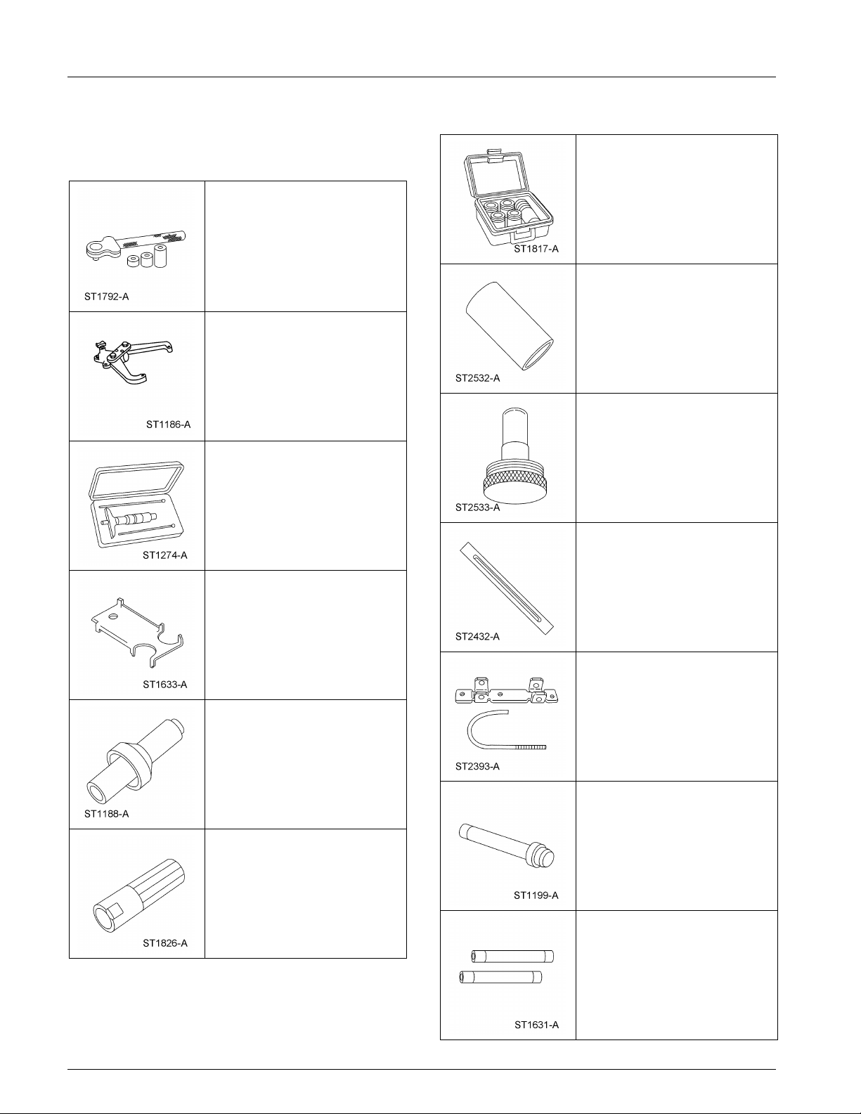
Special Tool(s)
Special Tool(s)
Alignment Set, Fluid Pump
307-S039 (T74P-77103-X)
Adjustment Set, Transmission
Band
307-S022 (T71P-77370-A)
Aligner, Fluid Pump Handle
307-431
Holding Fixture, Transmission
307-003 (T57L-500-B)
Aligner, Fluid Pump Pilot
307-432
Depth Micrometer
303-D026 (D80P-4201-A) or
equivalent
Alignment Gauge, TR Sensor
307-351 (T97L-70010-A)
Installer, Transmission
Extension Housing Oil Seal
307-038 (T74P-77052-A)
Sizer, Piston Seal
307-338 (T95L-70010-G)
Gauge Bar
307-400
Compressor, Servo Cover
307-402
Installer, Shift Shaft Fluid Seal
307-050 (T74P-77498-A)
Handle, Torque Converter
307-091 (T81P-7902-C)
(Continued)
Copyright 2004, Ford Motor Company
Last updated: 8/11/2005
(Continued)
2005 Mustang, 12/2004
Page 2
307-01-2 307-01-2Automatic Transaxle/Transmission
ASSEMBLY (Continued)
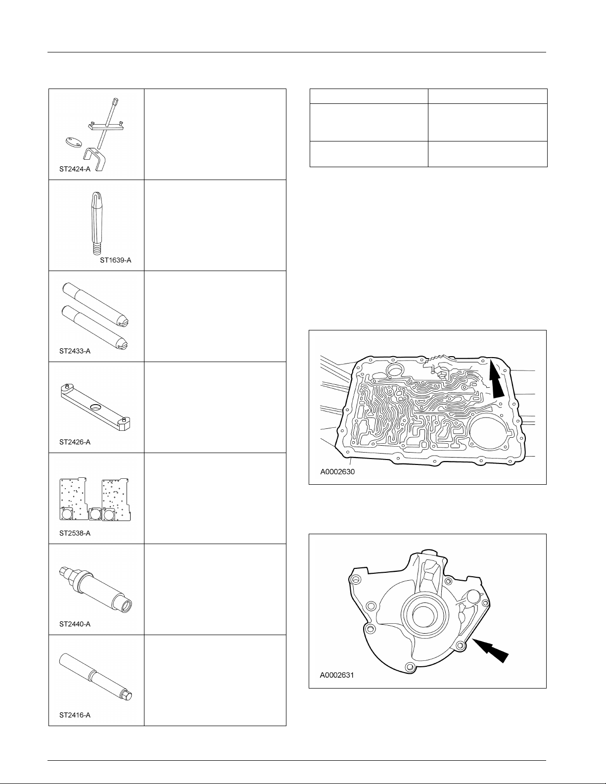
Special Tool(s) Material
Compressor, Cushion Spring Item Specification
307-401
MERCON V Automatic MERCON V
Transmission Fluid
XT-5-QM
Multi-Purpose Grease ESR-M1C159-A
XG-4
Aligner, Valve Body
307-334 (T95L-70010-C)
Alignment Pins, Transmission
Pump
307-399
Aligner, Flex Plate
307-403
Air Test Plate
307-433-01, 307-433-2,
307-433-3
1. Thoroughly clean the transmission case and
extension housing in solvent and blow dry with
compressed air.
2. Inspect the transmission case for the following:
• Stripped bolt hole threads
• Gasket and mating surfaces for burrs or
nicks
• Obstructions to vent and fluid passages
• Cracks or warpage
Installer, Drive Pinion flange
205-479
Installer, Output Shaft Flange
307-404
3. Inspect the extension housing for cracks, burrs
or warpage.
2005 Mustang, 12/2004
Page 3
307-01-3 307-01-3Automatic Transaxle/Transmission
ASSEMBLY (Continued)
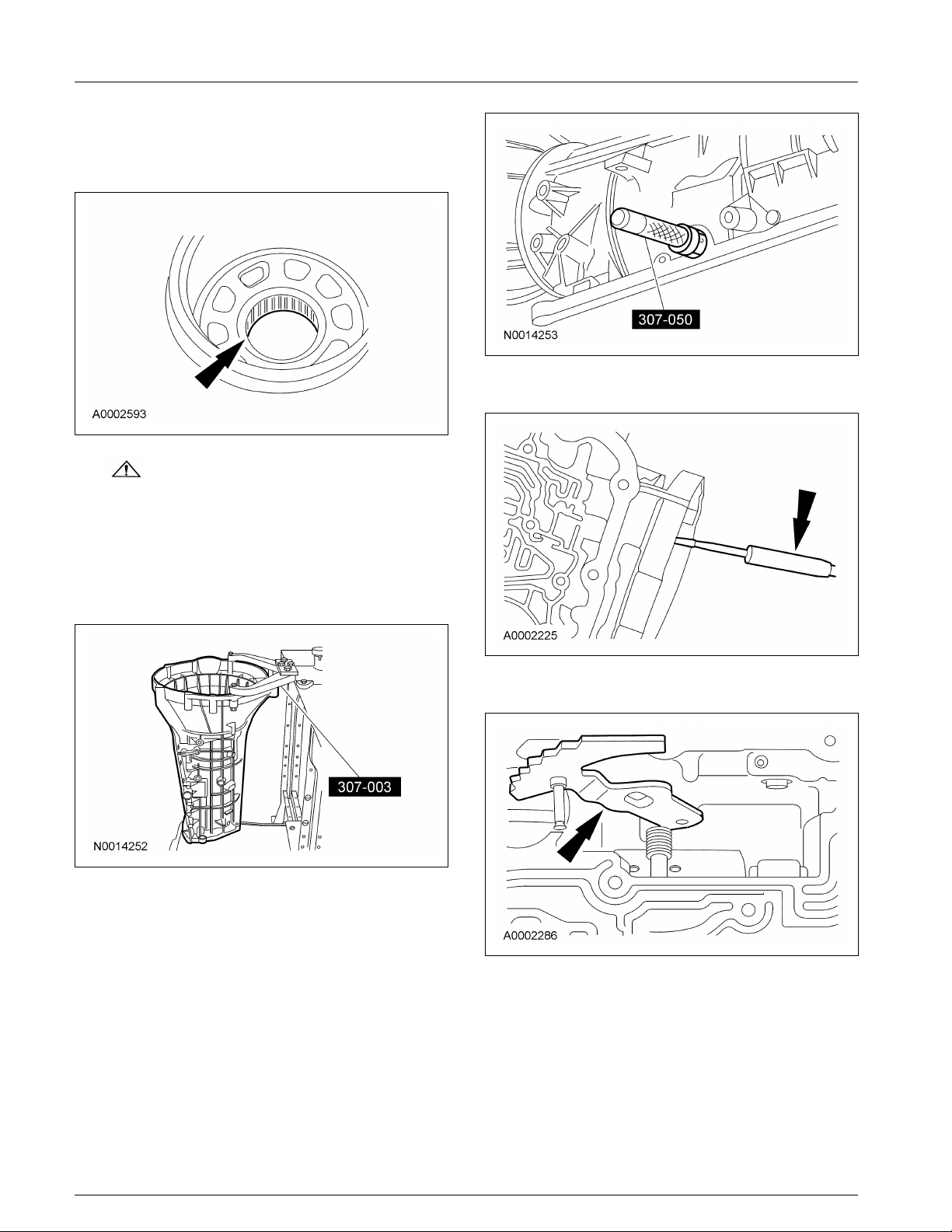
4. Inspect the case bearing for damage. If damage
to the case bearing is indicated, install a new
case.
7. Install the parking lever rod.
5. WARNING: Make sure the lock pin on
bench-mounted holding fixture is secure.
Failure to follow these instructions may
result in personal injury.
Using the special tool, install the transmission
into the bench with the converter housing
facing up.
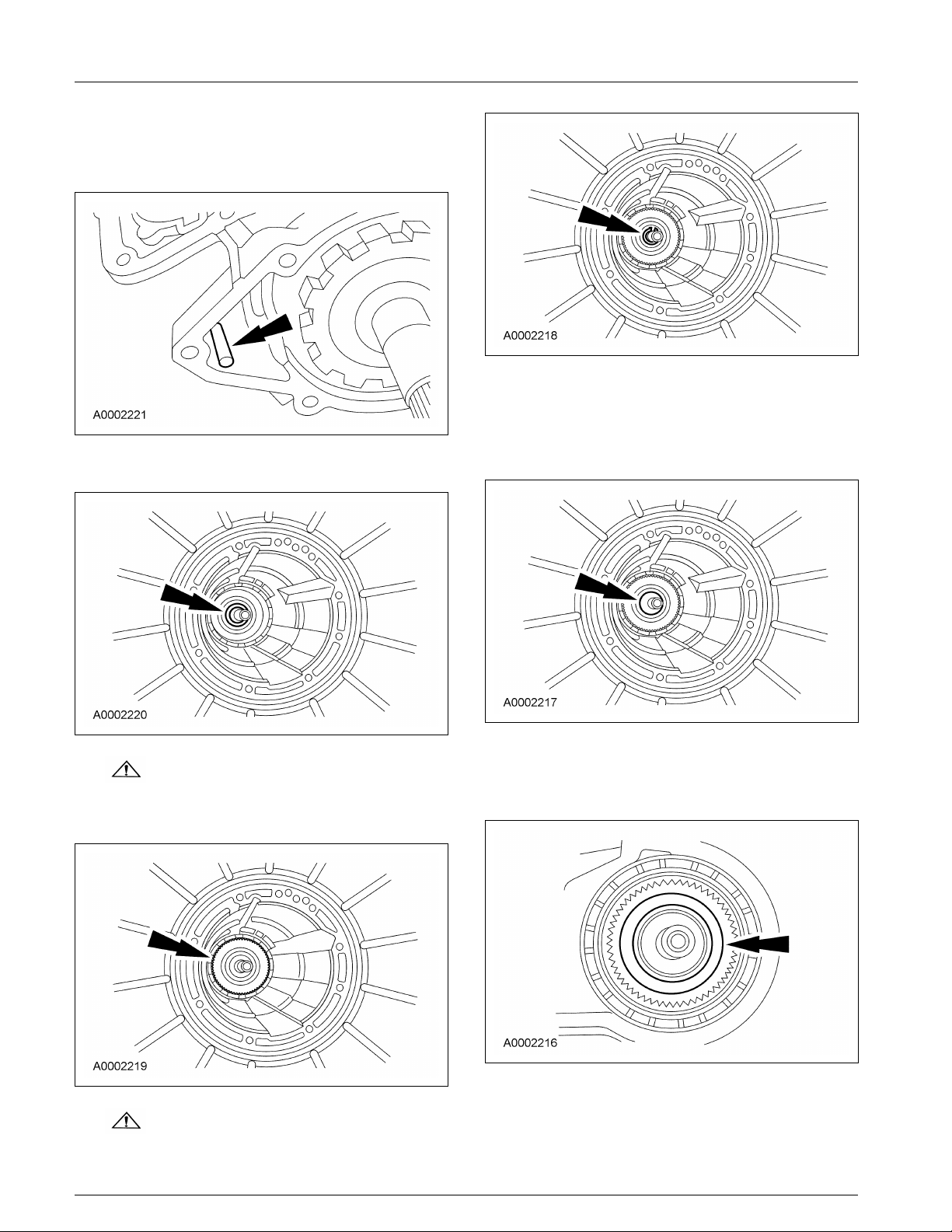
6. Using the special tool, install the manual
control lever shaft seal and lubricate it with
petroleum jelly.
8. Install the manual control lever.
2005 Mustang, 12/2004
Page 4

307-01-4 307-01-4Automatic Transaxle/Transmission
ASSEMBLY (Continued)
9. Assemble the manual valve inner lever and
parking lever actuating rod as shown.
10. CAUTION: Align the flats on the
manual valve inner lever with the flats on
the manual control lever shaft.
Install the manual control lever shaft.
12. CAUTION: Use care not to damage
the fluid pan rail surface when installing the
retaining pin.
NOTE: Align the manual control lever shaft
alignment groove with the manual control lever
shaft spring pin bore in the transmission case.
Install the manual control lever shaft spring pin.
• Tap the manual control lever shaft spring
pin into the transmission case.
11. Install the manual valve inner lever onto the
manual shaft and loosely install the nut.
13. CAUTION: To avoid damage, do not
allow the wrench to strike the manual valve
inner lever pin.
Tighten the nut.
• Tighten to 48 Nm (35 lb-ft).
2005 Mustang, 12/2004
Page 5
307-01-5 307-01-5Automatic Transaxle/Transmission
ASSEMBLY (Continued)
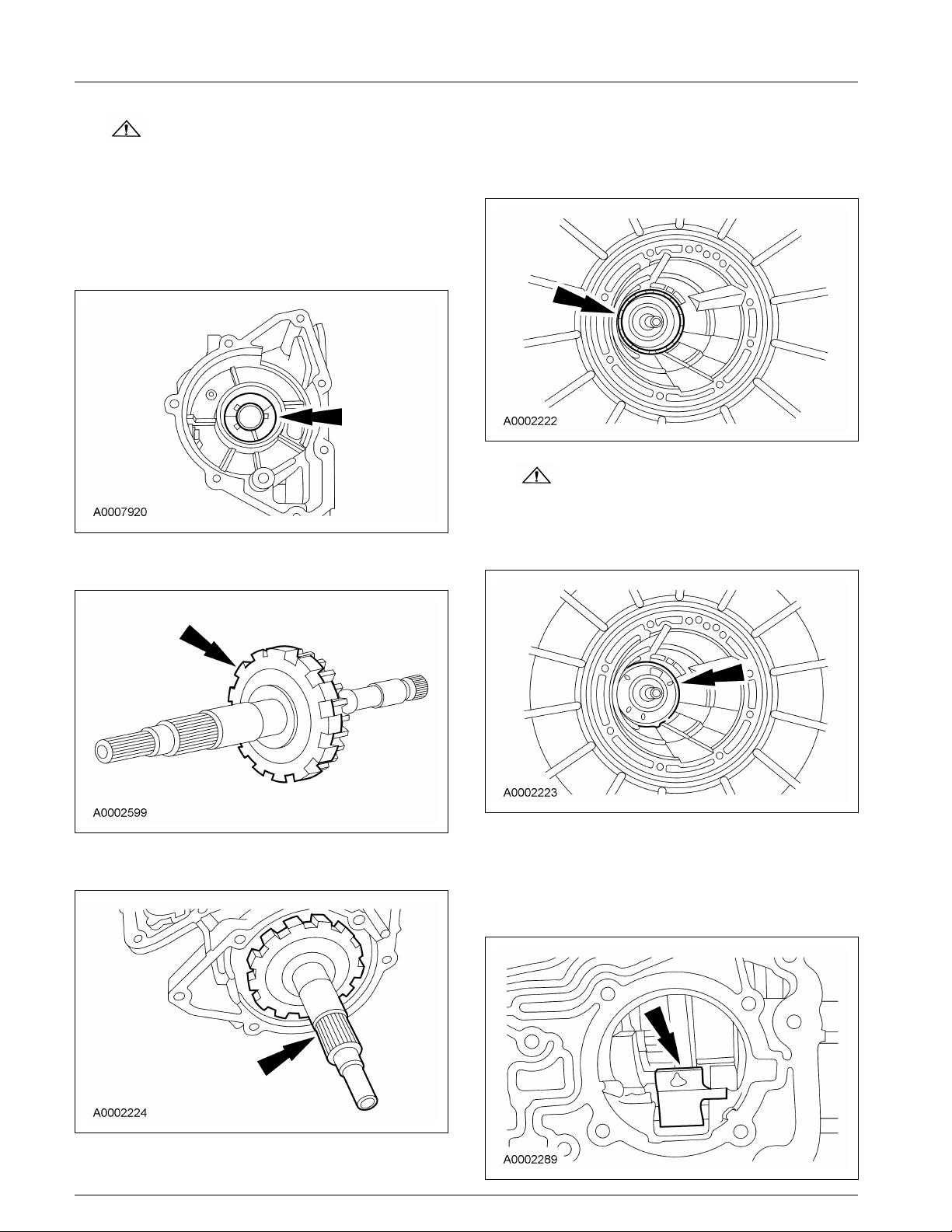
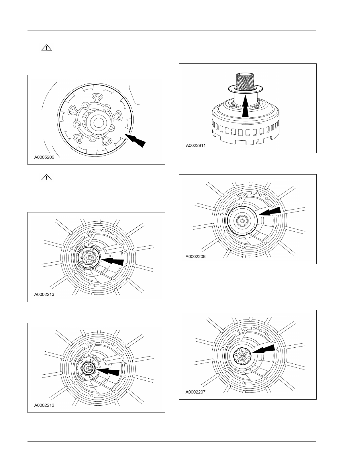
14. CAUTION: The tabs on the output
shaft thrust washer (No. 11) point into the
case. Make sure the thrust washer is
correctly seated.
Install the output shaft thrust washer (No. 11).
• Coat the output shaft thrust washer with
petroleum jelly.
15. Install the park gear on the output shaft.
17. Install the low/reverse brake drum.
• Rotate the low/reverse brake drum clockwise
to install.
18. CAUTION: Make sure band is resting
on the 2 anchor pins in the case.
Install the low/reverse band over the reverse
drum.
19. NOTE: The reverse band actuating lever must
16. Install the output shaft and park gear. fit into the notches in the band.
Install the reverse band actuating lever into the
reverse band.
2005 Mustang, 12/2004
Page 6
307-01-6 307-01-6Automatic Transaxle/Transmission
ASSEMBLY (Continued)
20. Install the reverse band actuating lever shaft
into the case and into the reverse band actuating
lever.
24. NOTE: Install the output shaft sleeve with the
cone facing up. This sleeve will snap into place
when correctly installed.
21. Install the No. 10 needle bearing into the case.
Install the output shaft sleeve.
22. CAUTION: Do not damage the seal
against the case during assembly.
Install the output shaft ring gear, hub and seal.
23. CAUTION: Always install a new
output shaft retaining ring.
Install a new output shaft retaining ring.
25. Install low/reverse planetary carrier needle
bearing (No. 9) onto the output shaft ring gear
and hub assembly.
2005 Mustang, 12/2004
Page 7
307-01-7 307-01-7Automatic Transaxle/Transmission
ASSEMBLY (Continued)
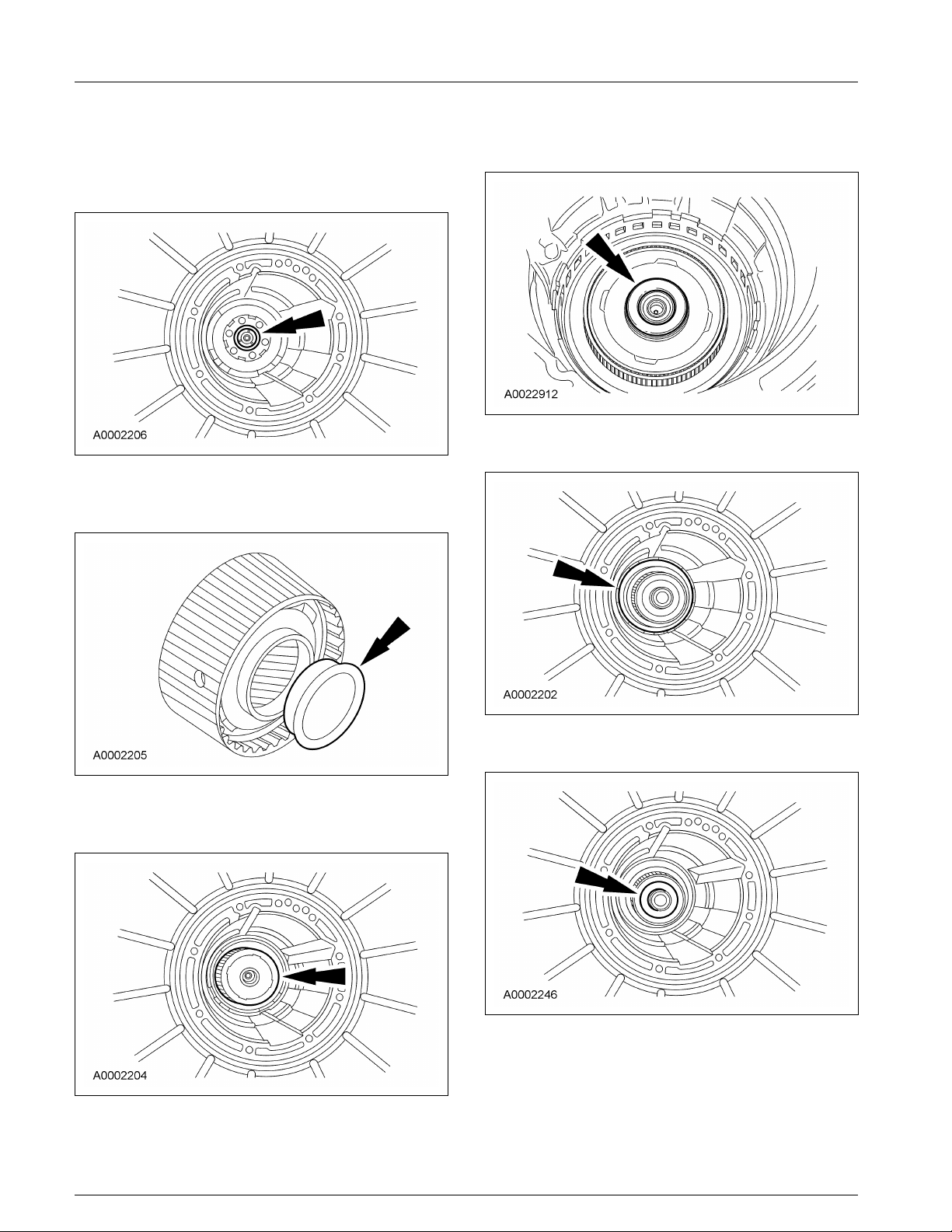
26. CAUTION: Make sure the needle
bearings stay in place.
Install the low/reverse planetary assembly.
27. CAUTION: The low/reverse brake
drum must be pulled forward to install the
low/reverse planet retaining ring.
Install the retaining ring.
29. Install the spacer on the input shell, using
petroleum jelly to hold it in place.
30. Install the input shell and sun gear assembly.
28. Install the No. 8 thrust bearing.
31. NOTE: The No. 13 bearing must be properly
seated in the forward planet assembly so the
sun gear can be installed correctly.
Install the forward planetary assembly.
2005 Mustang, 12/2004
Page 8
307-01-8 307-01-8Automatic Transaxle/Transmission
ASSEMBLY (Continued)
32. Install the No. 7 forward planet thrust bearing 35. Install the No. 6A forward ring gear hub thrust
into the forward ring gear and hub assembly. bearing into the forward ring gear and hub.
Use petroleum jelly to hold the bearing in
place.
36. Install the forward clutch cylinder.
33. Install the No. 6B forward clutch thrust washer
onto the forward ring gear hub.
34. Install the forward ring gear and hub as an
assembly.
37. Install the No. 5 thrust bearing.
2005 Mustang, 12/2004
Page 9

307-01-9 307-01-9Automatic Transaxle/Transmission
ASSEMBLY (Continued)
38. Install the intermediate servo piston and spring. 41. Using a depth micrometer with an 8-inch
• Lubricate the servo bore with clean
automatic transmission fluid.
39. Using the special tool, install the retaining ring.
extension, measure from the top of the gauge
bar to center support ledge in case at 4 places
90 degrees apart.
• Add the 4 measurements, divide by 4, and
record as dimension A.
40. Install the direct clutch drum.
42. CAUTION: The torque specifications
are critical for this procedure. Failure to use
the correct torque specifications may cause
transmission damage.
Install the special tool.
1 Install the special tool and the bolts using
the 2 pump screw locations at
approximately 6 and 12 o’clock positions.
X
Tighten to 15 Nm (11 lb-ft).
2 Tighten the center screw.
X
Tighten to 1 Nm (10 lb-in).
2005 Mustang, 12/2004
Page 10

307-01-10 307-01-10Automatic Transaxle/Transmission
ASSEMBLY (Continued)
43. NOTE: Align the disc holes on special tool 44. Add dimension B to C, divide by 2 and record
with the slot in gauge bar for correct as dimension D.
measurement.
Measure the distance from the top of the gauge
bar to the drum bearing surface through the
hole in the disc and record as dimension B.
Repeat measurement 180 degrees opposite side
of the special tool and record as dimension C.
45. Subtract A from D, and record as dimension E.
46. Select bearing from the following chart, using
dimension E.
Service Part Number
Dimension E (7D014) Bearing Thickness Identification (Notches)
1.69-1.87 mm XW4Z-CA 2.65-2.80 mm None
(0.066-0.074 in) (0.104-0.110 in)
1.88-2.04 mm XW4X-DA 2.83-2.98 mm One
(0.073-0.080 in) (0.111-0.116 in)
2.05-2.22 mm XW4Z-EA 3.01-3.16 mm Two
(0.081- 0.088 in) (0.118-0.124 in)
2.23-2.43 mm XW4Z-FA 3.21-3.36 mm Three
(0.088-0.096 in) (0.126-0.132 in)
47. NOTE: Make sure that the intermediate band
apply strut is aligned with the band notch.
NOTE: If the intermediate band is reused, it
must be installed in the same position as when
removed.
NOTE: The new intermediate band is dark in
color. This is a normal condition of the band.
Hairline cracks in the band are also considered
normal. Do not install a new band based solely
on the color.
Install the intermediate band.
2005 Mustang, 12/2004
Page 11

307-01-11 307-01-11Automatic Transaxle/Transmission
ASSEMBLY (Continued)
48. Install the intermediate band anchor strut.
51. Loosely install the screw.
49. CAUTION: To avoid a ‘‘fall-out’’
condition of the strut from the screw during
assembly and function, the small ‘‘U’’ shape
notch should be toward the band/case side
and the large ‘‘U’’ shape notch toward the
main control side.
Position the strut in the transmission case.
1 Band/case side of the anchor (small U
notch).
2 Main control side of the anchor (large U
notch).
50. CAUTION: If the strut is installed
incorrectly, transmission damage will occur.
Check to make sure that the intermediate band
anchor strut is installed in the correct
orientation to the case and adjustment screw.
52. Install the intermediate band apply strut.
2005 Mustang, 12/2004
Page 12

307-01-12 307-01-12Automatic Transaxle/Transmission
ASSEMBLY (Continued)
53. CAUTION: If the strut is installed
incorrectly, transmission damage will occur.
Check to make sure that the intermediate band
apply strut is installed in the correct orientation
to the case and piston rod.
54. Install the selected No. 4 thrust washer on the
direct clutch drum.
• Coat the thrust washer with petroleum jelly.
56. Install the center support locknut and cage.
57. Loosely install the screw.
55. NOTE: Align the center support screw hole
with correct case hole.
Install the center support.
2005 Mustang, 12/2004
Page 13

307-01-13 307-01-13Automatic Transaxle/Transmission
ASSEMBLY (Continued)
58. CAUTION: Install the center support
retaining ring with the tapered side facing
up.
CAUTION: Make sure the notch
opening is not obstructed by the center
support retaining ring.
Install the center support retaining ring.
1 Make sure the center support retaining ring
is installed with the tapered side facing up.
2 Make sure the opening of the center support
retaining ring is positioned correctly.
60. Install the overdrive ring gear, overdrive
one-way clutch and center shaft assembly.
59. Install the center shaft thrust bearing (No. 3).
61. CAUTION: Do not bend the trigger
wheel. Make sure that the No. 2 thrust
bearing is in this assembly.
Install the planetary gear overdrive carrier.
2005 Mustang, 12/2004
Page 14

307-01-14 307-01-14Automatic Transaxle/Transmission
ASSEMBLY (Continued)
62. Install the overdrive brake drum and coast 65. NOTE: If the overdrive band is reused, it must
clutch drum assembly. be installed in the same position as when
removed.
NOTE: Make sure that the overdrive band
apply strut is aligned with the band notch.
NOTE: The new overdrive band is dark in
color. This is a normal condition of the band.
Hairline cracks in the band are also considered
normal. Do not install a new band based solely
on the color.
Install the overdrive band.
63. Install the overdrive band servo piston and
spring.
• Lubricate the servo bore with clean
automatic transmission fluid.
64. Using the special tools, install the retaining
ring.
66. Install the overdrive anchor strut.
2005 Mustang, 12/2004
Page 15

307-01-15 307-01-15Automatic Transaxle/Transmission
ASSEMBLY (Continued)
67. CAUTION: To avoid a ‘‘fall-out’’
condition of the strut from the screw during
assembly and function, the small ‘‘U’’ shape
notch should be toward the band/case side
and the large ‘‘U’’ shape notch toward the
main control side.
Position the strut in the transmission case.
1 Band/case side of the anchor (small U
notch).
2 Main control side of the anchor (large U
notch).
70. Loosely install the screw.
68. CAUTION: If the strut is installed
incorrectly, transmission damage will occur.
Check to make sure that the intermediate band
anchor strut is installed in the correct
orientation to the case and adjustment screw.
69. CAUTION: If the strut is installed
incorrectly, transmission damage will occur.
Check to make sure that the overdrive band
anchor strut is installed in the correct
orientation to the case and adjustment screw.
71. Install the overdrive apply strut.
2005 Mustang, 12/2004
Page 16

307-01-16 307-01-16Automatic Transaxle/Transmission
ASSEMBLY (Continued)
72. CAUTION: If the strut is installed
incorrectly, transmission damage will occur.
Check to make sure that the overdrive band
apply strut is installed in the correct orientation
to the case and piston rod.
73. CAUTION: The torque specifications
are critical for this procedure. Failure to use
the correct torque specifications may cause
transmission damage.
Install the special tool.
1 Install the special tool and the bolts using
the 2 pump screw locations at
approximately 6 and 12 o’clock positions.
X
Tighten to 15 Nm (11 lb-ft).
2 Tighten the center screw.
X
Tighten to 1 Nm (10 lb-in).
74. NOTE: Align the disc holes on special tool
with the slot in gauge bar for correct
measurement.
Measure the distance from the top of the gauge
bar to the drum bearing surface through the
hole in the disc and record as dimension A.
Repeat measurement 180 degrees opposite side
of the special tool and record as dimension B.
75. Add dimension A to B, divide by 2 and record
as dimension C.
76. Subtract the thickness of the gauge bar 17.78
mm (0.70 in) from dimension C, and record as
dimension D.
77. Select the No. 1 thrust bearing from the
following chart using dimension D.
Service Part Number
Dimension D (7D014) Bearing Thickness Identification (Color/ID)
38.05-38.13 mm F7TZ-TA 1.55-1.60 mm (0.061-0.063 White
(1.50 in) in)
38.14-38.28 mm F7TZ-MA 1.75-1.80 mm (0.069-0.071 Green
(1.50-1.51 in) in)
2005 Mustang, 12/2004
Page 17

307-01-17 307-01-17Automatic Transaxle/Transmission
ASSEMBLY (Continued)
Service Part Number
Dimension D (7D014) Bearing Thickness Identification (Color/ID)
38.29-38.42 mm F7TZ-NA 1.85-1.90 mm (0.073-0.075 Red
(1.51 in) in)
38.43-38.61 mm F7TZ-RA 2.05-2.10 mm (0.081-0.083 Black
(1.51-1.52 in) in)
38.62-38.74 mm (1.52-1.53 F7TZ-SA 2.15-2.20 mm (0.095-0.097 Yellow
in) in)
78. Install the selected No. 1 fluid pump input
thrust washer.
• Coat the fluid pump input thrust washer
with petroleum jelly.
79. Install the special tools into the transmission
case.
80. Install the pump gasket.
81. CAUTION: Make sure that the fluid
pump inlet thrust washer (No. 1), selective
thrust washer, fluid pump gasket and the
fluid pump-to-case O-ring seal remain in the
correct position throughout this step.
Install the fluid pump.
2005 Mustang, 12/2004
Page 18

307-01-18 307-01-18Automatic Transaxle/Transmission
ASSEMBLY (Continued)
82. CAUTION: The special tools must be
used to correctly align the pump with the
adapter plate to reduce gear noise, bushing
failure and leakage.
Using the special tool, align the fluid pump to
the adapter plate.
85. CAUTION: Do not allow overdrive
band adjustment screw to back out. Band
strut could fall out of position.
CAUTION: Install, but do not tighten,
a new locknut on the band adjustment screw.
Apply petroleum jelly to the locknut seal.
83. Install screws. Tighten the screws in a star
pattern.
• Tighten to 25 Nm (18 lb-ft).
Install a new locknut on the band adjustment
screw.
84. Remove the special tools and install the 2
remaining screws.
• Tighten to 25 Nm (18 lb-ft).
2005 Mustang, 12/2004
Page 19

307-01-19 307-01-19Automatic Transaxle/Transmission
ASSEMBLY (Continued)
86. CAUTION: The overdrive servo must
be installed prior to band adjustment.
Using the special tool, tighten the overdrive
band adjustment screw. Then back off the
screw exactly 1.5 turns and hold that position.
• Tighten to 14 Nm (10 lb-ft).
89. CAUTION: The intermediate servo
must be installed prior to band adjustment.
Tighten the intermediate band adjustment screw.
Then back off the screw exactly 1.5 turns and
hold that position.
• Tighten to 14 Nm (10 lb-ft).
87. Tighten the overdrive band locknut.
1 Hold the overdrive band adjustment screw
stationary.
2 Tighten the overdrive band locknut.
X
Tighten to 54 Nm (40 lb-ft).
88. CAUTION: Do not allow the
intermediate band adjusting screw to back
out. Band strut could fall out of position.
90. Tighten the intermediate band locknut.
1 Hold the intermediate band adjustment
screw stationary.
2 Tighten the intermediate band locknut.
X
Tighten to 54 Nm (40 lb-ft).
CAUTION: Install, but do not tighten,
a new locknut on the band adjustment screw.
Apply petroleum jelly to the locknut seal.
Install new nut on the band adjustment screw.
2005 Mustang, 12/2004
Page 20

307-01-20 307-01-20Automatic Transaxle/Transmission
ASSEMBLY (Continued)
91. Tighten the center support screw. 94. Using the special tools, install the main control
• Tighten to 11 Nm (8 lb-ft).
92. Using the special tools, carry out the air
pressure test procedure. For additional
information, refer to Special Testing Procedures
in this section.
valve body and loosely install the screws.
1 Install the short screw.
2 Install the screw with the larger head.
3 Install the remaining screws.
95. Remove the special tools, and loosely install the
screw.
93. Install the special tools into the transmission
case.
2005 Mustang, 12/2004
Page 21

307-01-21 307-01-21Automatic Transaxle/Transmission
ASSEMBLY (Continued)
96. Tighten the screws in the sequence shown.
• Tighten to 10 Nm (89 lb-in).
97. With the manual lever in the NEUTRAL 98. Install new O-ring seals on the solenoid body
position, install the manual valve detent spring. connector. Lubricate the O-ring seals with clean
• Tighten to 10 Nm (89 lb-in).
automatic transmission fluid.
2005 Mustang, 12/2004
Page 22

307-01-22 307-01-22Automatic Transaxle/Transmission
ASSEMBLY (Continued)
99. CAUTION: Inspect the transmission
case bore to make sure it is free of debris
and not damaged. If damaged, transmission
leak may occur.
Install the solenoid body. Tighten the screws in
sequence shown.
• Tighten to 8 Nm (71 lb-in).
102. NOTE: The transmission fluid pan gasket is
reusable. Clean and inspect for damage. If not
damaged, the gasket should be reused.
Install the transmission fluid pan and gasket
and loosely install the screws.
100. Install the reverse servo. Tighten the bolts in
the sequence shown in 2 stages.
• Stage 1: Tighten to 5 Nm (44 lb-in).
• Stage 2: Tighten to 11 Nm (8 lb-ft).
101. CAUTION: Lubricate the fluid filter
seals with clean automatic transmission
fluid or they may be damaged.
NOTE: Make sure that the fluid filter seals
are correctly seated on the filter.
Lubricate the seals and install the transmission
fluid filter.
• Tighten to 10 Nm (89 lb-in).
103. Tighten the 16 screws in a crisscross
sequence.
• Tighten to 11 Nm (8 lb-ft).
2005 Mustang, 12/2004
Page 23

307-01-23 307-01-23Automatic Transaxle/Transmission
ASSEMBLY (Continued)
104. Install the parking pawl assembly and gasket. 107. Using the special tools, install the output shaft
1 Install the parking pawl shaft.
2 Install the parking pawl return spring.
3 Install the parking pawl.
4 Install a new gasket.
flange.
108. Install a new nut.
• Tighten to 131 Nm (97 lb-ft).
105. Install the extension housing.
• Tighten to 25 Nm (18 lb-ft).
106. Using the special tool, install the extension
housing seal.
109. CAUTION: The digital transmission
range sensor must fit flush against the boss
on the case to prevent damage to the
sensor.
Install the digital transmission range (TR)
sensor and loosely install the screws.
2005 Mustang, 12/2004
Page 24

307-01-24 307-01-24Automatic Transaxle/Transmission
ASSEMBLY (Continued)
110. CAUTION: Tightening one screw
before tightening the other may cause the
sensor to bind or become damaged.
NOTE: The manual lever must be in the
NEUTRAL position.
Using the special tool, align the digital TR
sensor and tighten the screws in an alternating
sequence.
• Tighten 10 Nm (89 lb-in).
112. Using the special tool, make sure that the fluid
pump gear seal ring is fully seated.
113. Remove the special tool.
111. CAUTION: The splines of the input
shaft are not the same length on both ends.
The shaft end with the shorter splines goes
into the fluid pump.
Install the input shaft.
2005 Mustang, 12/2004
Page 25

307-01-25 307-01-25Automatic Transaxle/Transmission
ASSEMBLY (Continued)
114. CAUTION: Do not damage the fluid
pump gear O-ring seal when installing
torque converter.
CAUTION: Make sure the converter
hub is fully engaged in the pump support
and gear and rotates freely. Do not damage
the hub seal.
CAUTION: If the torque converter
slides out, the hub seal may be damaged.
Lubricate the converter hub with clean
automatic transmission fluid.
117. CAUTION: The special tool must be
used to correctly align the adapter plate to
the converter or transmission damage could
occur.
In order to correctly install the special
service tool, it must be installed using one
round and one oblong hole. Using two
oblong holes will cause damage to the
transmission.
NOTE: Position the adapter plate on the
torque converter and identify the position of
the orange or green paint daub on the
converter face.
115. WARNING: The torque converter can
fall out if the transmission is tipped. Failure
to follow these instructions may cause
personal injury.
Using the special tools, install the torque
converter by pushing and rotating.
If the vehicle is equipped, use the special tool
to install the torque converter flex plate
adapter assembly and 8 nuts.
• Tighten to 44 Nm (33 lb-ft).
116. Lubricate the torque converter pilot hub with
multi-purpose grease.
2005 Mustang, 12/2004
Page 26

307-01-26 307-01-26Automatic Transaxle/Transmission
ASSEMBLY (Continued)
118. Remove the special tool and install the 120. NOTE: Inspect O-ring seal for damage. Install
remaining torque converter flex plate adapter new if damaged. Lubricate the O-ring seals
nuts. with petroleum jelly to prevent damage to the
• Tighten to 44 Nm (33 lb-ft).
119. Using one of the speed sensor holes, fill the
transmission with 8.5L (9 quarts) of automatic
transmission fluid.
O-ring seals.
Install the sensors.
• Tighten to 10 Nm (89 lb-in).
2005 Mustang, 12/2004
 Loading...