

Page 1
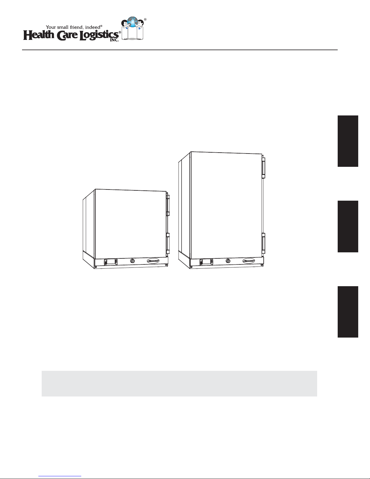
18688/18690
REF1/REF2
High-Performance
Compact Refrigerators
Installation, Operation and Service Manual
English
REF1 REF2
18688 18690
Following installation, please forward this manual
Español Français
totheappropriate operations person.
Call Free: 1.800.848.1633 • Fax Free: 1.800.447.2923
© Health Care Logistics, Inc. 2012
Web: www.GoHCL.com • Email: [email protected]
Page 2

Contents
Speci cations . . . . . . . . . . . . . . . . . . . . . . . . . . . . . . . . . . . . . . . . . . . . . . . . . . . . . . . . . . . . . . . . . . . . . . . . . . . . . . . . 3
Dimensions . . . . . . . . . . . . . . . . . . . . . . . . . . . . . . . . . . . . . . . . . . . . . . . . . . . . . . . . . . . . . . . . . . . . . . . . . . . . . . . . 3
Ambient Information . . . . . . . . . . . . . . . . . . . . . . . . . . . . . . . . . . . . . . . . . . . . . . . . . . . . . . . . . . . . . . . . . . . . . . . . . 3
Clearances . . . . . . . . . . . . . . . . . . . . . . . . . . . . . . . . . . . . . . . . . . . . . . . . . . . . . . . . . . . . . . . . . . . . . . . . . . . . . . . . 3
Electrical . . . . . . . . . . . . . . . . . . . . . . . . . . . . . . . . . . . . . . . . . . . . . . . . . . . . . . . . . . . . . . . . . . . . . . . . . . . . . . . . . . 3
Refrigeration . . . . . . . . . . . . . . . . . . . . . . . . . . . . . . . . . . . . . . . . . . . . . . . . . . . . . . . . . . . . . . . . . . . . . . . . . . . . . . . 3
Heat Rejection . . . . . . . . . . . . . . . . . . . . . . . . . . . . . . . . . . . . . . . . . . . . . . . . . . . . . . . . . . . . . . . . . . . . . . . . . . . . . 3
Installation . . . . . . . . . . . . . . . . . . . . . . . . . . . . . . . . . . . . . . . . . . . . . . . . . . . . . . . . . . . . . . . . . . . . . . . . . . . . . . . . . . . 4
Installing Foot Pads - Required . . . . . . . . . . . . . . . . . . . . . . . . . . . . . . . . . . . . . . . . . . . . . . . . . . . . . . . . . . . . . . . . 4
Installing Shelves - Required . . . . . . . . . . . . . . . . . . . . . . . . . . . . . . . . . . . . . . . . . . . . . . . . . . . . . . . . . . . . . . . . . . 4
Installing Glycerine Solution in Product Simulation Bottle - Required . . . . . . . . . . . . . . . . . . . . . . . . . . . . . . . . . . . 4
Locating the Refrigerator . . . . . . . . . . . . . . . . . . . . . . . . . . . . . . . . . . . . . . . . . . . . . . . . . . . . . . . . . . . . . . . . . . . . . 5
Reversing the Door Swing - Optional . . . . . . . . . . . . . . . . . . . . . . . . . . . . . . . . . . . . . . . . . . . . . . . . . . . . . . . . . . . . 6
Changing Temperature Display - Optional . . . . . . . . . . . . . . . . . . . . . . . . . . . . . . . . . . . . . . . . . . . . . . . . . . . . . . . . 7
Alarming Functions . . . . . . . . . . . . . . . . . . . . . . . . . . . . . . . . . . . . . . . . . . . . . . . . . . . . . . . . . . . . . . . . . . . . . . . . . . . . 7
To Change the Alarm Delay . . . . . . . . . . . . . . . . . . . . . . . . . . . . . . . . . . . . . . . . . . . . . . . . . . . . . . . . . . . . . . . . . . . 8
Disabling the Alarm . . . . . . . . . . . . . . . . . . . . . . . . . . . . . . . . . . . . . . . . . . . . . . . . . . . . . . . . . . . . . . . . . . . . . . . . . 8
Maximum and Minimum Temperature Function . . . . . . . . . . . . . . . . . . . . . . . . . . . . . . . . . . . . . . . . . . . . . . . . . . . . . 8
To see Minimum Temperature Recorded . . . . . . . . . . . . . . . . . . . . . . . . . . . . . . . . . . . . . . . . . . . . . . . . . . . . . . . . . 8
To See Maximum Temperature Recorded . . . . . . . . . . . . . . . . . . . . . . . . . . . . . . . . . . . . . . . . . . . . . . . . . . . . . . . . 8
"Sleep" Function . . . . . . . . . . . . . . . . . . . . . . . . . . . . . . . . . . . . . . . . . . . . . . . . . . . . . . . . . . . . . . . . . . . . . . . . . . . . . . 8
Operation . . . . . . . . . . . . . . . . . . . . . . . . . . . . . . . . . . . . . . . . . . . . . . . . . . . . . . . . . . . . . . . . . . . . . . . . . . . . . . . . . . . . 9
Automatic Defrost . . . . . . . . . . . . . . . . . . . . . . . . . . . . . . . . . . . . . . . . . . . . . . . . . . . . . . . . . . . . . . . . . . . . . . . . . . . 9
Controller Operation . . . . . . . . . . . . . . . . . . . . . . . . . . . . . . . . . . . . . . . . . . . . . . . . . . . . . . . . . . . . . . . . . . . . . . . . . 9
Controller Security . . . . . . . . . . . . . . . . . . . . . . . . . . . . . . . . . . . . . . . . . . . . . . . . . . . . . . . . . . . . . . . . . . . . . . . . . 10
Programming Refrigerator from a Program Key (download) . . . . . . . . . . . . . . . . . . . . . . . . . . . . . . . . . . . . . . . . . 10
Connecting to Dry Contacts for Remote Alarming . . . . . . . . . . . . . . . . . . . . . . . . . . . . . . . . . . . . . . . . . . . . . . . . . 10
Cleaning . . . . . . . . . . . . . . . . . . . . . . . . . . . . . . . . . . . . . . . . . . . . . . . . . . . . . . . . . . . . . . . . . . . . . . . . . . . . . . . . . . . . 12
Annual Cleaning . . . . . . . . . . . . . . . . . . . . . . . . . . . . . . . . . . . . . . . . . . . . . . . . . . . . . . . . . . . . . . . . . . . . . . . . . . . 12
Service . . . . . . . . . . . . . . . . . . . . . . . . . . . . . . . . . . . . . . . . . . . . . . . . . . . . . . . . . . . . . . . . . . . . . . . . . . . . . . . . . . . . . 12
Door Gasket Replacement . . . . . . . . . . . . . . . . . . . . . . . . . . . . . . . . . . . . . . . . . . . . . . . . . . . . . . . . . . . . . . . . . . 12
Access Compressor Compartment . . . . . . . . . . . . . . . . . . . . . . . . . . . . . . . . . . . . . . . . . . . . . . . . . . . . . . . . . . . . 13
Controller Replacement . . . . . . . . . . . . . . . . . . . . . . . . . . . . . . . . . . . . . . . . . . . . . . . . . . . . . . . . . . . . . . . . . . . . . 13
Wiring Diagram . . . . . . . . . . . . . . . . . . . . . . . . . . . . . . . . . . . . . . . . . . . . . . . . . . . . . . . . . . . . . . . . . . . . . . . . . . . . 14
Refrigeration System . . . . . . . . . . . . . . . . . . . . . . . . . . . . . . . . . . . . . . . . . . . . . . . . . . . . . . . . . . . . . . . . . . . . . . . 14
Refrigerator Troubleshooting . . . . . . . . . . . . . . . . . . . . . . . . . . . . . . . . . . . . . . . . . . . . . . . . . . . . . . . . . . . . . . . . . . . 15
Replacement Parts . . . . . . . . . . . . . . . . . . . . . . . . . . . . . . . . . . . . . . . . . . . . . . . . . . . . . . . . . . . . . . . . . . . . . . . . . . . 16
Exterior Components . . . . . . . . . . . . . . . . . . . . . . . . . . . . . . . . . . . . . . . . . . . . . . . . . . . . . . . . . . . . . . . . . . . . . . . 16
Door and Gasket Components . . . . . . . . . . . . . . . . . . . . . . . . . . . . . . . . . . . . . . . . . . . . . . . . . . . . . . . . . . . . . . . . 17
Evaporator and Motor . . . . . . . . . . . . . . . . . . . . . . . . . . . . . . . . . . . . . . . . . . . . . . . . . . . . . . . . . . . . . . . . . . . . . . . 18
Compressor Components . . . . . . . . . . . . . . . . . . . . . . . . . . . . . . . . . . . . . . . . . . . . . . . . . . . . . . . . . . . . . . . . . . . . 19
2 REF1/REF2 Compact Refrigerators
Page 3
Speci cations –––––––––––––––––––––––––––––––––––––––––––––––––––––
Dimensions
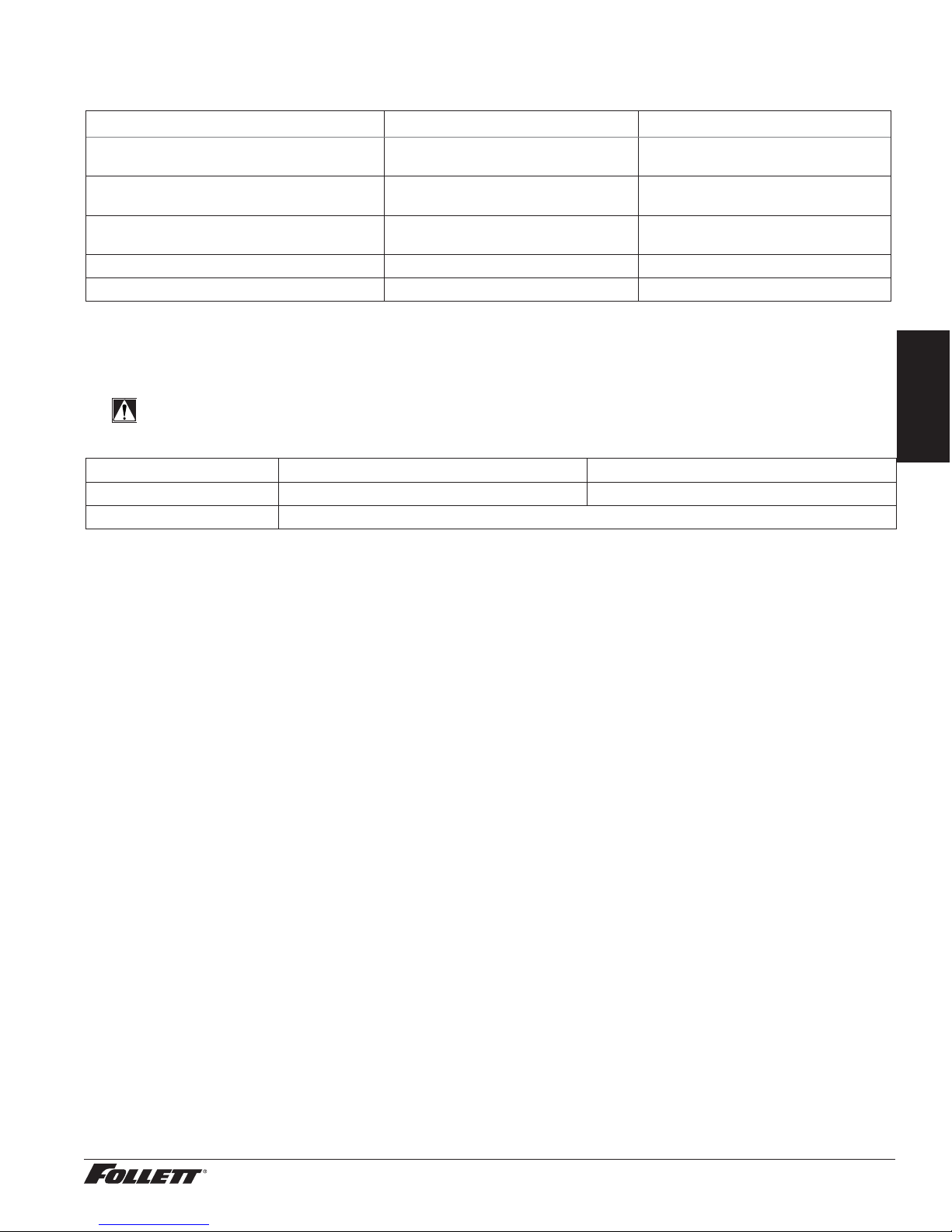
REF1 REF2
Dimensions (external)
Dimensions (internal)
Shelf Size
Capacity 1 cu ft (28 L) 1.8 cu ft (51 L)
Weight (uncrated)* 73 lbs (33 kg) 87 lbs (39 kg)
* Add 22 lbs/10 kg for packaging.
18.6" W x 24" D x 17.75" H
(47 cm x 61 cm x 45 cm)
14.5" W x 10" D x 11.25" H
(37 cm x 25 cm x 29 cm)
13.75 W x 9 D
(35 cm x 23 cm)
18.6" W x 24" D x 27.75" H
(47 cm x 61 cm x 70 cm)
14.50" W x 10" D x 21.25" H
(37 cm x 25 cm x 54 cm)
13.75 W x 9 D
(35 cm x 23 cm)
Ambient Information
CAUTION!
The REF1 and REF2 are for indoor use only.
Optimum Maximum
Air Temperature ≤80 F (28 C) 100 F (38 C)
Relative Humidity 60% max
Clearances
§ Dependent upon location. See Locating the Refrigerator on page 5.
Electrical
§ 115V, 60 Hz, 1 phase, 1.8A, maximum fuse 15A
§ Connect to dedicated 15A circuit, fuse or breaker. Note: It is preferred that circuit be protected by a GFCI.
Refrigeration
§ Refrigerant R134a – 3.4 ounces (96 grams)
Heat Rejection
§ 190 BTU/hr (56 W)
English
REF1/REF2 Compact Refrigerators 3
Page 4
Installation ––––––––––––––––––––––––––––––––––––––––––––––––––––––––
Installing Foot Pads - Required
CAUTION!
Use caution when tipping the refrigerator during foot pad installation. DO NOT EXCEED 30° angle.
Tipping more than 30° can result in compressor malfunction.
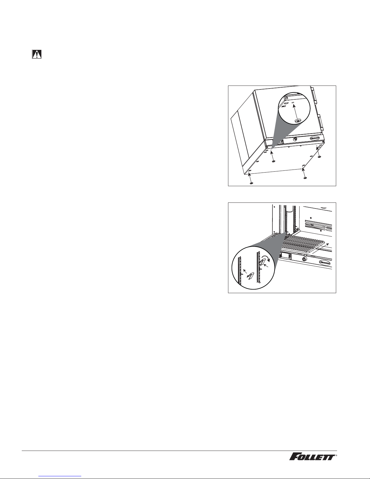
1. Remove the foot pads (4) from the plastic bag packed inside the
refrigerator.
2. Carefully tip the refrigerator back, ensuring that it can not fall, to
expose the four foot pad holes (Fig. 1).
3. Position the foot pad over the foot pad hole and press the
center of the foot pad until it is fully seated. The foot pads
extend 1/8" (3.2 mm) below the base of the refrigerator (Fig. 1).
Installing Shelves - Required
1. Remove shelves and shelf brackets packed inside refrigerator.
(If ordered, nd additional shelf accessory in separate box.)
2. Install shelf brackets in pilasters (insert top tab, squeeze and
push in lower tab) (Fig. 2).
Fig. 1
Fig. 2
Installing Glycerine Solution in Product Simulation Bottle - Required
1. Remove the 60 ml bottle from the bracket located in the upper left corner of the refrigerator.
2. Remove the top and ll the bottle with a 50/50 solution of glycerine and water.
3. Replace the top (and probe).
4. Reinsert bottle into the bracket.
Note: The probe monitors product temperature and must be installed for proper display and alarming.
4 REF1/REF2 Compact Refrigerators
Page 5
Locating the Refrigerator
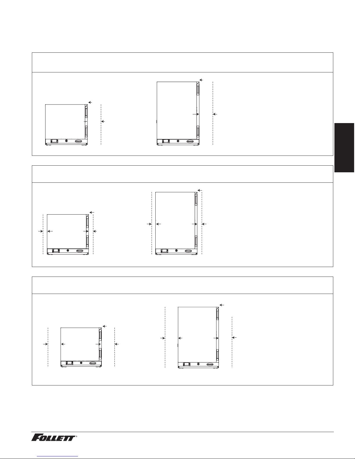
Performance of REF1 and REF2 is affected by ambient temperature and location. To ensure proper performance,
please refer to the following drawings and con rm that the clearance requirements are met. There is no clearance
requirement for the back of the refrigerator so it can be placed against the wall.
80 F (27 C) and 60% RH – located under overhanging cabinet or shelf with zero top clearance
Requires 6" clearance on either right or left side
zero top clearance
zero top clearance
6" (153 mm) minimum
6" (153 mm) minimum
air clearance require
right or left side
REF1 REF2
80 F (27 C) and 60% RH – unrestricted topclearance location
Requires 2" clearance on both sides and unrestricted top clearance
air clearance require
right or left side
unrestricted top
English
unrestricted top
2" (51 mm) minimum air
clearance require both
sides
REF1
2" (51 mm) minimum air
clearance require both
sides
REF2
100 F (38 C) – maximum temperature location with zero top clearance
Requires 6" clearance on both sides
zero top clearance
zero top clearance
6" (153 mm) minimum
air clearance require
both sides
REF1 REF2
6" (153 mm) minimum
air clearance require
both sides
REF1/REF2 Compact Refrigerators 5
Page 6
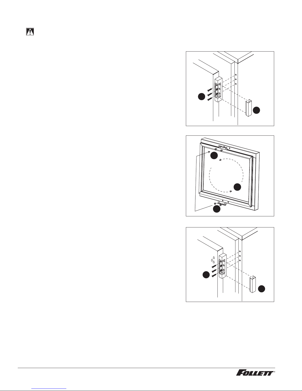
Reversing the Door Swing - Optional
CAUTION!
When reinstalling hinge screws, 242 blue Loctite* MUST be applied to screws. Torque screws to 25 in-lbs.
1. Use at screwdriver to carefully remove hinge covers. Care
should be taken to avoid scratching chrome cover or refrigerator
body (Fig. 3.1).
2. Support door and remove screws attaching hinge to refrigerator
cabinet (Fig. 3.2).
3. Remove plugs from opposite side of unit and cover hinge screw
holes.
4. Remove screws holding lock strike-bracket at "bottom" inside of
door (Fig. 4.1).
5. Remove plugs from inside of door "top" and install bracket.
6. Plug "bottom" holes with retained plugs and install lock strike-
bracket to "top" inside of door (Fig. 4.2).
7. Reverse door 180° so that lock strike-bracket is on the bottom
inside of door (Fig. 4.3).
8. Apply 242 blue Loctite* to hinge screws, reinstall screws
(torqued to 25 in-lbs) (Fig. 5.1) and replace hinge covers
(Fig.5.2).
Fig. 3
2
1
Fig. 4
2
3
*Loctite is a registered trademark of Henkel Corporation in the United States and other countries.
1
Fig. 5
1
2
6 REF1/REF2 Compact Refrigerators
Page 7
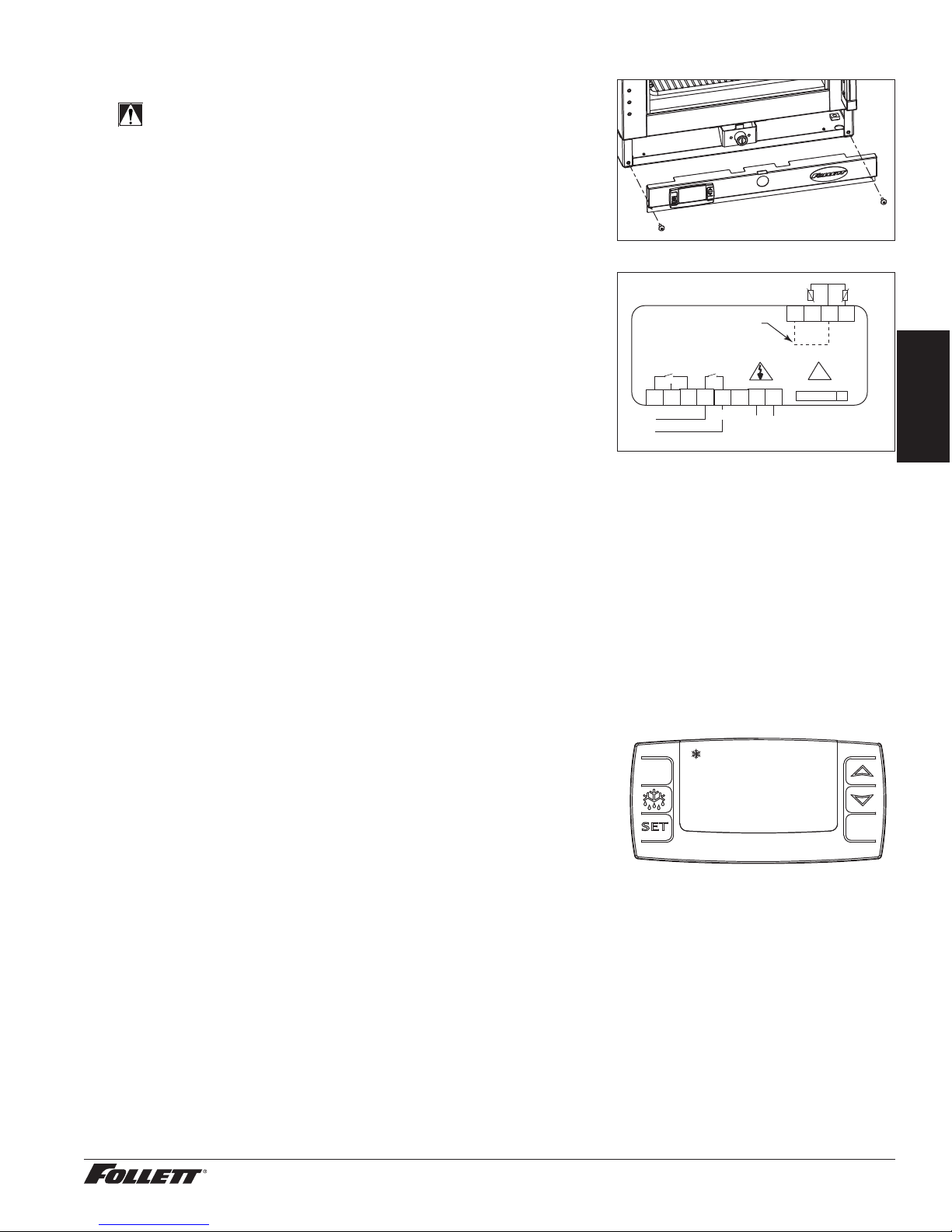
Changing Temperature Display - Optional
NOTICE!
It is important that you review the temperature/alarm settings
after you change the temperature display. The controller
contains two, separate temperature channels; F and C.
Changes made to the factory default settings while displaying
temperatures in F will not automatically transfer when you
change the temperature display to C.
Fig. 6
Follett REF1 and REF2 refrigerators are factory-set to display
temperatures in degrees F. To display the temperature in degrees C,
follow these steps:
1. Move the power switch on lower rear panel to OFF and unplug
the refrigerator.
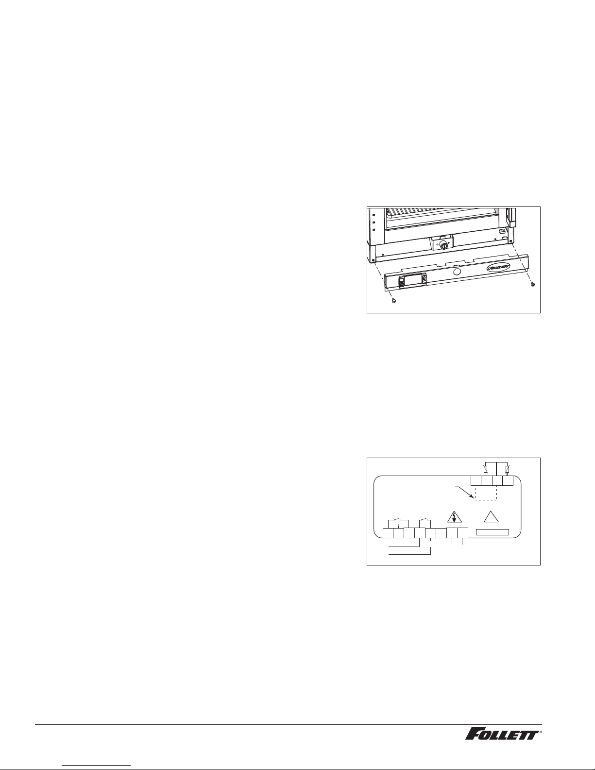
2. Remove the front lower panel cover (Fig. 6) to access the
controller.
3. Locate jumper wires for pins #9 and #11 (Fig. 7) and connect.
4. Reinstall the front lower panel cover.
Fig. 7
AUX/ALARM
F/C Jumper Wire
1
3 2
C NO NC
Line
4
Supply
Probe
12
9 10 11 12
11
!
r
6 75
8
Controller programming
Supply
key (accessory)
rrrr
5. Plug in the refrigerator and return the power switch to ON.
Alarming Functions –––––––––––––––––––––––––––––––––––––––––––––––––
Follett’s controller provides local high and low temperature alarming. If product temperature goes above or below
the set temperature range, an audible alarm sounds and the display ashes. Alarming stops automatically as soon
as soon as the temperature returns to normal values.
Most refrigerated medications should be stored between 36 F and 46 F (2 C and 8 C). The controller is factory-set
to maintain product temperature at 39 F (4 C) and to display temperature in degrees F. If you want the temperature
to display in degrees C, follow the instructions in Changing Temperature Display - Optional and make that change
before setting your alarm values.
Note: The alarm function has no battery backup. If your refrigerator is not on a "red circuit" with generator backup,
you may want to consider Follett’s alarm module with battery backup (Item # 00112185) for maximum product
security. Controller is factory-set with a high-alarm default setting of 100 F (38 C).
To set low temperature alarm value
1. Press SET and DOWN ARROW and hold for 3 seconds until
HY appears.
2. Press DOWN ARROW until ALL appears.
3. Press SET to display current setting.
4. Press UP or DOWN ARROW to change to desired temperature.
5. Press SET to accept new value.
6. To set high temperature alarm value
7. Press SET and DOWN ARROW and hold for 3 seconds until HY appears.
8. Press DOWN ARROW until ALU appears.
9. Press SET to display current setting.
10. Press UP or DOWN ARROW to change to desired temperature.
11. Press SET to accept new value.
To mute the alarm
1. Press any key to mute the alarm.
2. The alarm will not sound until another alarm occurs.
English
REF1/REF2 Compact Refrigerators 7
Page 8
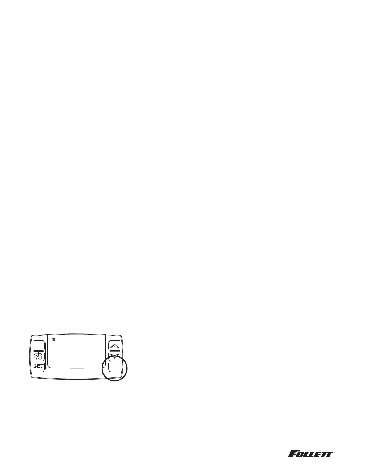
To Change the Alarm Delay
The alarming feature is factory-set with a 1 minute delay to avoid nuisance alarming. Follow these steps to program
the delay interval from 0 to 255 minutes.
1. Press SET and DOWN ARROW and hold for 3 seconds until HY appears.
2. Press DOWN ARROW until ALd appears
3. Press SET to display current delay setting.
4. Press UP or DOWN ARROW to change to desired delay interval.
5. Press SET to accept new value.
Disabling the Alarm
If local alarming is not desired, alarm set points can be changed to effectively disable all possible alarms. To disable
alarm functions, follow the instructions in Alarming Functions on page 7 for setting low and high temperature alarm
values.
1. Set the low temperature alarm value for -40 F (-40 C).
2. Set the low temperature alarm value for 100 F (37.8).
Product will never reach these values, even in the event of refrigerator malfunction, and the alarm will not sound.
Maximum and Minimum Temperature Function ––––––––––––––––––––––––––
Follett’s controller allows you to see the maximum and minimum product temperature experienced since last "reset".
This feature does not provide any information on duration of the temperature values.
To see Minimum Temperature Recorded
1. Press and release DOWN arrow.
2. Lo message displays followed by minimum temperature recorded.
3. Press and hold SET for more than 3 seconds to reset.
To See Maximum Temperature Recorded
1. Press and release UP arrow
2. Hi message displays followed by maximum temperature recorded.
3. Press and hold SET for more than 3 seconds to reset.
"Sleep" Function –––––––––––––––––––––––––––––––––––––––––––––––––––
You may not want the Follett temperature display when using a third-party temperature monitoring system with
its own temperature display. You can put the Follett controller "to sleep" to avoid confusion. The compressor icon
remains illuminated when the compressor is running.
1. Press BOTTOM RIGHT button to put display to sleep.
2. Press BOTTOM RIGHT button to return to display mode.
8 REF1/REF2 Compact Refrigerators
Page 9
Operation –––––––––––––––––––––––––––––––––––––––––––––––––––––––––
The temperature control board and P1 probe indicate when the refrigeration system is required to turn on and off.
The refrigeration system removes heat from the cabinet interior and rejects it to the surrounding room air. When
the cabinet interior temperature reaches 4 F (2.2 C) above the controller set point, the probe signals the controller
to turn the refrigeration system on. The normally open controller contacts close and energize the condenser fan
motor and compressor. The evaporator fan runs continuously. The compressor uses a PTC device to turn on the
compressor motor.
When the cabinet interior temperature falls to the set point, the probe signals the controller to turn the refrigeration
system off. The controller contacts reopen, which de-energizes the evaporator, condenser fan motors and the
compressor.
Automatic Defrost
REF Series refrigerators do not require manual defrosting. The unit defrosts automatically when the condensing unit
is in the OFF cycle.
Any accumulated frost on the evaporator coil melts during the OFF cycle. The condensate drains to a plastic drain
pan mounted below the condensing unit. The heat from the condensing unit evaporates any condensate in the drain
pan.
English
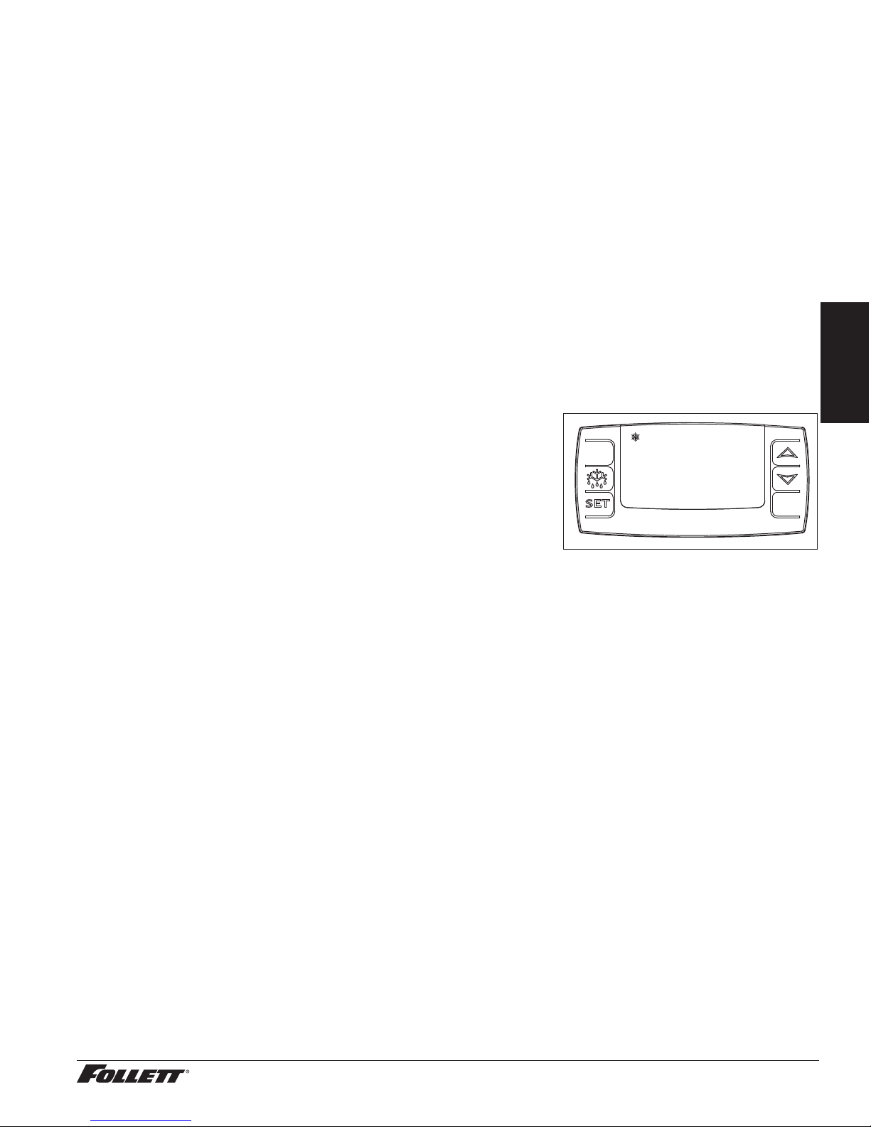
Controller Operation
In normal operation, the controller displays temperatures in degrees F
(default) or user-selected degrees C. F temperatures are displayed to the
nearest degree, C temperatures are displayed to one decimal point. A
snow ake LED displays when the compressor is running. The controller
is pre-programmed with a 38F (3.3 C) set point.
Follett presets its refrigeration system to hold medications at
approximately 39 F (3.8 C).
If you are storing prepackaged food in this unit, NSF requires the set
point be changed to 36 F (2.2 C) to maintain food below 40 F (4.4 C).
All set points have a 4 F (2.2 C) differential. This differential means that
with a 38 F (3 C) set point, for example, the compressor will turn off at 38
F (3 C) and turn on when it reaches 42 F (6 C). This maintains product
temperature for medications within the recommended range of 36 F to
46 F (2C to 8 C).
Note: Display (Fig. 8) always reverts to P2 product temperature display
after settings are accepted. It is important to note that P2 product
temperature probe drives all alarming functions.
To display temperature set point
1. Press and release SET and current cut-out temperature displays for approximately 5 seconds.
2. Display returns to current product temperature.
To change temperature set point
1. Press and hold SET for 3 seconds, until the current cut-out temperature displays and F or C ashes.
2. Press UP or DOWN arrows to set desired cut-out temperature.
3. Press and release SET and new cut-out temperature blinks three times.
4. Display returns to current product temperature.
Fig. 8
38
°F
REF1/REF2 Compact Refrigerators 9
Page 10
Controller Security
The controller panel can be locked to prevent unauthorized programming changes. In locked mode, the controller
displays cabinet temperature and set point only.
To lock the controller
1. Simultaneously press and hold UP and DOWN ARROW buttons for 3 seconds, until "PoF" displays ( ashes
3 times).
2. Programmer is now locked.
To unlock the controller
1. Simultaneously press and hold UP and DOWN ARROW buttons for 3 seconds, until "Pon" displays ( ashes
3 times).
2. Programmer is now unlocked.
Programming Refrigerator from a Program Key (download)
1. Move the power switch on lower rear panel to OFF.
2. Remove the front lower panel cover to access the controller
(Fig. 9).
3. Insert appropriate programmed key into 5-pin receptacle located
on back of controller.
4. Move the power switch to ON.
5. Values from key automatically download to refrigerator ("dol"
message blinks followed by "end").
6. After 10 seconds, display returns to current refrigerator
temperature and controller restarts with new values.
7. Move the power switch to OFF.
8. Remove programming key.
9. Reinstall panel.
10. Move the power switch to ON.
Note: An "Err" message displays for failed programming. Turn
refrigerator OFF then ON to restart download, or remove key
toabort.
Connecting to Dry Contacts for Remote Alarming
1. Move the power switch on lower rear panel to OFF and unplug
the refrigerator.
2. Remove the front lower panel cover (Fig. 9) to access the
controller.
3. Connect two wires from the remote alarm device to contacts
1(C) and 2(NO or NC) on the temperature controller (Fig. 10).
4. Carefully route wires through the back of the refrigerator; do not
to run wires over surfaces that may damage the wiring.
5. Reinstall the front lower panel cover.
6. Connect remote alarm device.
7. Plug in the refrigerator and return the power switch to ON.
Fig. 9
Fig. 10
AUX/ALARM
1
C NO NC
F/C Jumper Wire
3 2
Line
4
Supply
Probe
12
9 10 11 12
11
!
r
6 75
8
Controller programming
Supply
key (accessory)
rrrr
10 REF1/REF2 Compact Refrigerators
Page 11
Installing Third-party Temperature Probe
Facilities using a third-party alarming and/or temperature monitoring
system need to install the third-party probe in the refrigerator. Follett
recommends removing any stored product before performing this
procedure.
Refer to for instruction to disable Follett integral alarming to eliminate
confusion between two monitoring services.
1. Move the power switch on lower rear panel to OFF and unplug
the refrigerator.
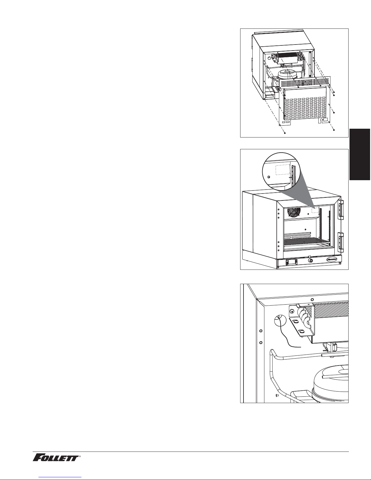
2. Remove the rear panel of the refrigerator (Fig. 11).
3. Open front door of refrigerator and remove shelf/shelves, if
installed, for better access.
4. From inside the refrigerator, push and fold the perforated cut out
located on the inside, upper-right hand corner (Fig.12).
5. Use a long screwdriver or drill to create a hole (up to 1"
(25.4mm) diameter) through the exposed foam insulation.
6. From inside the refrigerator, feed non-probe end of wire through
opening (Fig. 13).
7. Secure probe to interior cabinet wall to avoid product
interference.
8. Gently pull on non-probe end of wire to remove slack from
inside of refrigerator.
9. Use Permagum* or equivalent sealant to replace foam
insulation (removed in Step 5) to ensure proper performance of
refrigerator.
10. Remove any debris that may have fallen into the drain pan or
condensor area.
11. Route non-probe end of wire through appropriate ventilation
hole in refrigerator rear panel.
12. Reinstall the rear panel.
13. Connect non-probe end of wiring to monitoring device.
14. Plug in the refrigerator and return the power switch to ON.
15. Follow instructions found in Disabling the Alarm on page 8 to
disable alarm functions.
* Permagum is a registered trademark of the Presstite Engineering Company.
Fig. 11
Fig. 12
Fig. 13
English
REF1/REF2 Compact Refrigerators 11
Page 12
Cleaning
CAUTION!
Use only non-chlorine-based cleaners. Use of cleaners containing chlorine can cause staining and pitting
of the stainless steel
Interior
Using a sponge or soft cloth, clean unit with a non-abrasive, non-chlorinated, all-purpose detergent.
Exterior
Wipe exterior with a soft cloth in the direction of grain as needed. Stainless steel polish may be used to enhance
the nish of the unit.
Annual Cleaning
Removal of dust and other particulates from air intake areas and the condenser is important for proper operation.
Under certain conditions, some environments with large amounts of dust may require more frequent cleaning.
1. Move the power switch on lower rear panel to OFF and unplug
the refrigerator.
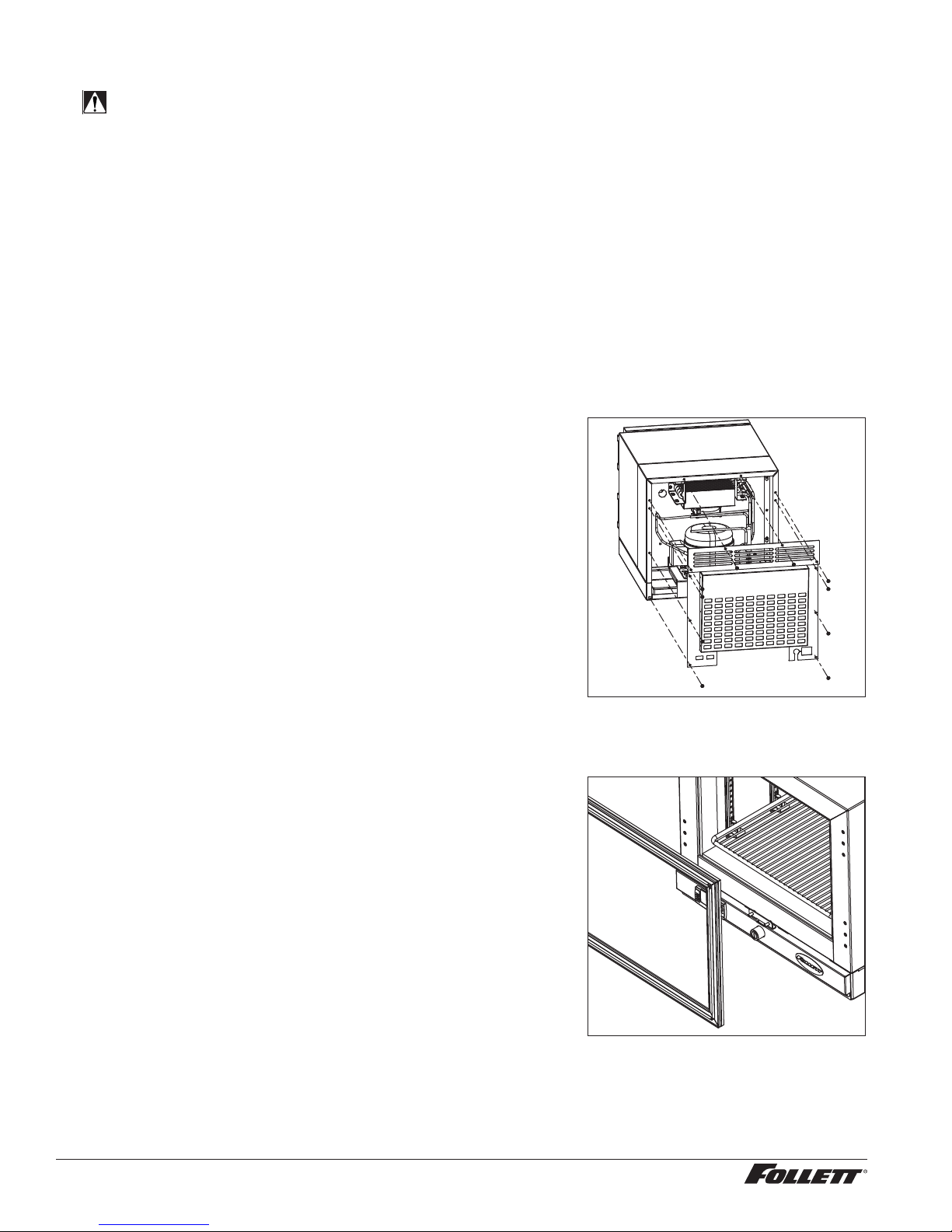
2. Remove rear panel (Fig. 14).
3. Remove drain pan.
4. Clean drain pan with a non-abrasive, non-chlorinated
all-purpose detergent.
5. Reinstall drain pan.
6. Use a vacuum cleaner with brush attachment to clean
condenser, compressor motor, and related parts.
7. Reinstall rear panel.
Fig. 14
Service –––––––––––––––––––––––––––––––––––––––––––––––––––––––––––
Door Gasket Replacement
1. Remove existing gasket from mounting track (Fig. 15).
2. Verify mounting track is free of any remaining gasket material.
3. Align new gasket with mounting track and press rmly in place.
4. Open and close door, checking for proper gasket seal without
pinching against refrigerator.
Fig. 15
12 REF1/REF2 Compact Refrigerators
Page 13
Access Compressor Compartment
Follett’s compressor compartment allows technicians to gain full
access to the condensing unit from the refrigerator back without cutting
refrigerant lines.
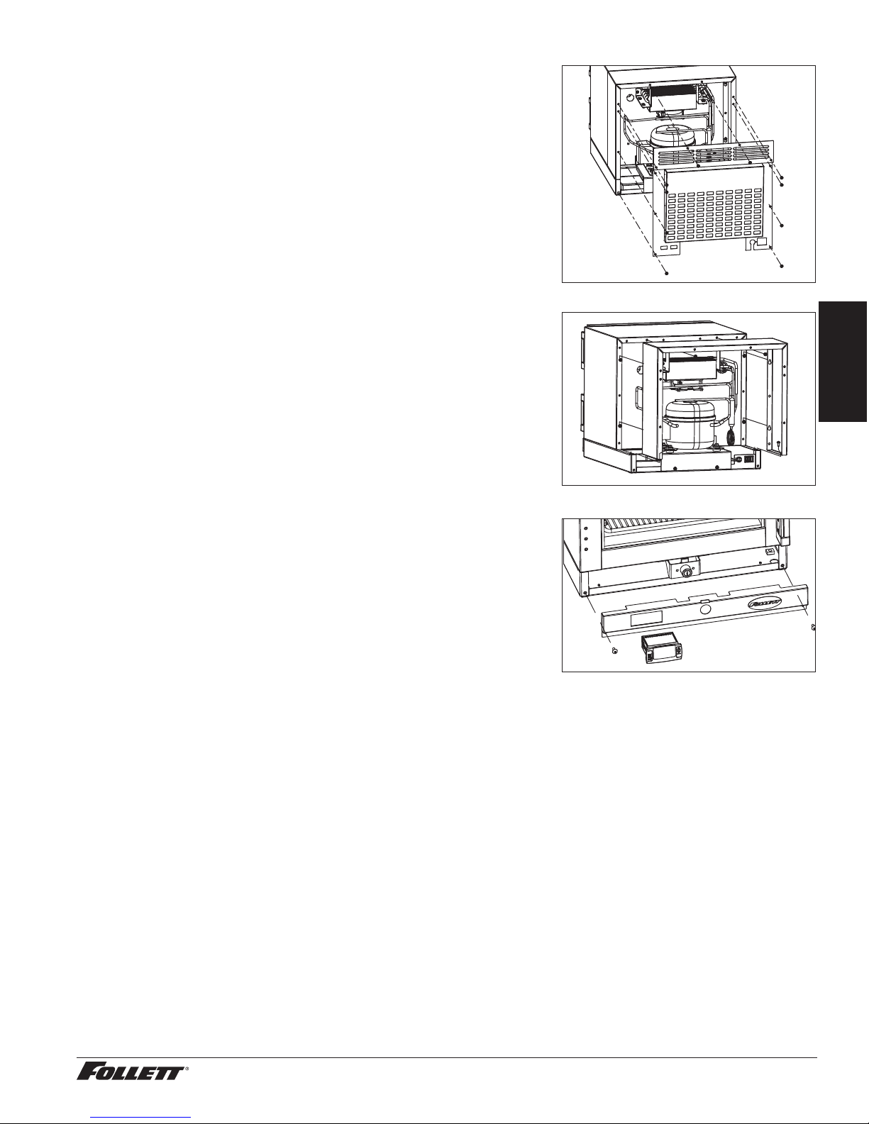
1. Remove rear panel (Fig. 16).
2. Remove two screws facing downward that secure the panel
assembly to the base plate.
3. Loosen the six screws that secure the rear panel to the back of
the refrigeration box. Lift rear panel off to access (Fig. 17).
Fig. 16
Fig. 17
English
Controller Replacement
1. Disconnect power to unit by moving switch on lower rear panel
to the OFF position, and removing power cord from wall outlet.
2. Remove 2 screws from front panel to access back of controller
(Fig. 18).
3. Disconnect wiring from controller back. (Note wire locations.)
4. Push in at center of controller side brackets to release and slide
brackets back and off of controller.
5. Push controller out through front of front panel.
6. Slide brackets onto sides of controller and push against back of
panel.
7. Reconnect wiring to controller in same location noted in Step 3.
8. Replace front panel, restore power and test operation.
Re-program replacement controller if necessary using program
key ordered with controller replacement kit.
Fig. 18
REF1/REF2 Compact Refrigerators 13
Page 14
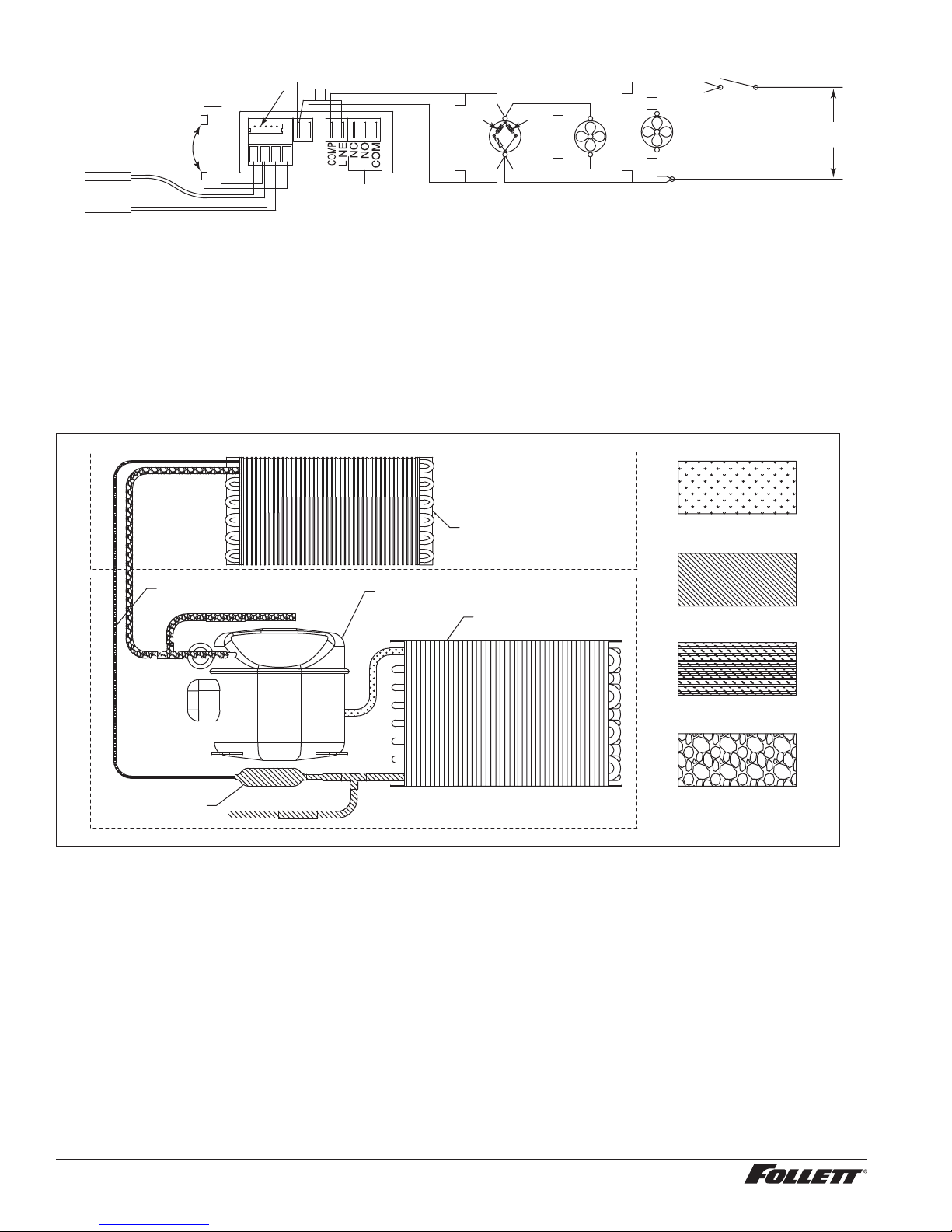
Wiring Diagram
HOT(L1)
120VAC
NEUTRAL
CONNECT FOR DEG C
DISCONNECT FOR DEG F
P1 CONTROL
P2 ALARM
PROGRAM PORT
12 11 10 9
L2(N)
L1(H)
4
ALARM RELAY
5
STA RT
7
C
N
COMP COND
RUN
8
12
13
FAN
14
15
3
EVAP
FAN
POWER
SWITCH
Refrigeration System
The REF Series refrigeration system is designed to give many years of trouble-free service. Except for routine
cleaning of the air-cooled condenser and related parts, the refrigeration system requires no service or maintenance.
The system uses a capillary tube and is critically charged. All refrigerator components are easily accessed from the
rear of the unit.
Please contact Follett Service Department in the event of a refrigeration problem that requires evacuation and
recharging.
Refrigeration System Diagram
CAPILLARY TUBE
FILTER-DRIER
COMPRESSOR
EVAPORATOR
CONDENSER
HIGH-PRESSURE VAPOR
HIGH-PRESSURE LIQUID
LOW-PRESSURE LIQUID
LOW-PRESSURE VAPOR
14 REF1/REF2 Compact Refrigerators
Page 15
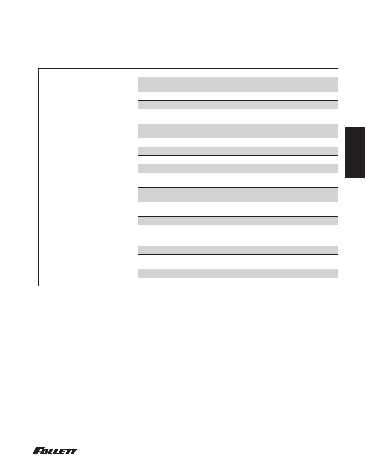
Refrigerator Troubleshooting –––––––––––––––––––––––––––––––––––––––––
Before calling for service
1. Check that unit is plugged in.
2. Test outlet with another appliance to verify power.
Troubleshooting Matrix
Sympton Possible Cause Solution
Refrigerator does not operate (no
components run).
Compressor does not run. Thermal overload open or defective. Allow to cool or replace.
Evaporator fan motor does not run. Defective fan motor. Replace fan motor.
Refrigerator does not shut off. Controller not sensing cut-off
Refrigerator does not maintain
temperature (all components run).
If problems persist after following this basic troubleshooting guide, call Follett technical service group
at (877) 612-5086 or +1 (610) 252-7301.
Power switch faulty or in OFF position;
loose connection.
Refrigerator not plugged in. Connect plug.
No power to cord. Restore power.
Temp controller not energizing
components.
Probe not sensing set point
temperature.
Capacitor and/or relay defective. Replace as required.
Compressor defective. Replace compressor.
temperature.
Controller keeping refrigeration system
energized.
Condensor or evaporator coil needs
cleaning.
Faulty door gasket. Replace door gasket.
Excessively high ambient or
indadequate air clearance.
Refrigerant leak. Locate and repair leak.
Incorrect refrigerant charge. Recover, evaluate and weigh in correct
Plugged capillary tube. Replace capillary tube and lter drier.
Inefficient compressor. Consult technical services.
Turn power switch to ON; check switch
and connections.
Check controller contact terminals for
power. Replace controller if needed.
Replace controller and/or probe.
Replace controller and/or probe.
Replace controller.
Clean coils.
Maximum recommended ambient
is 100F (38 F). See Locating the
Refrigerator on page 5.
charge.
English
REF1/REF2 Compact Refrigerators 15
Page 16
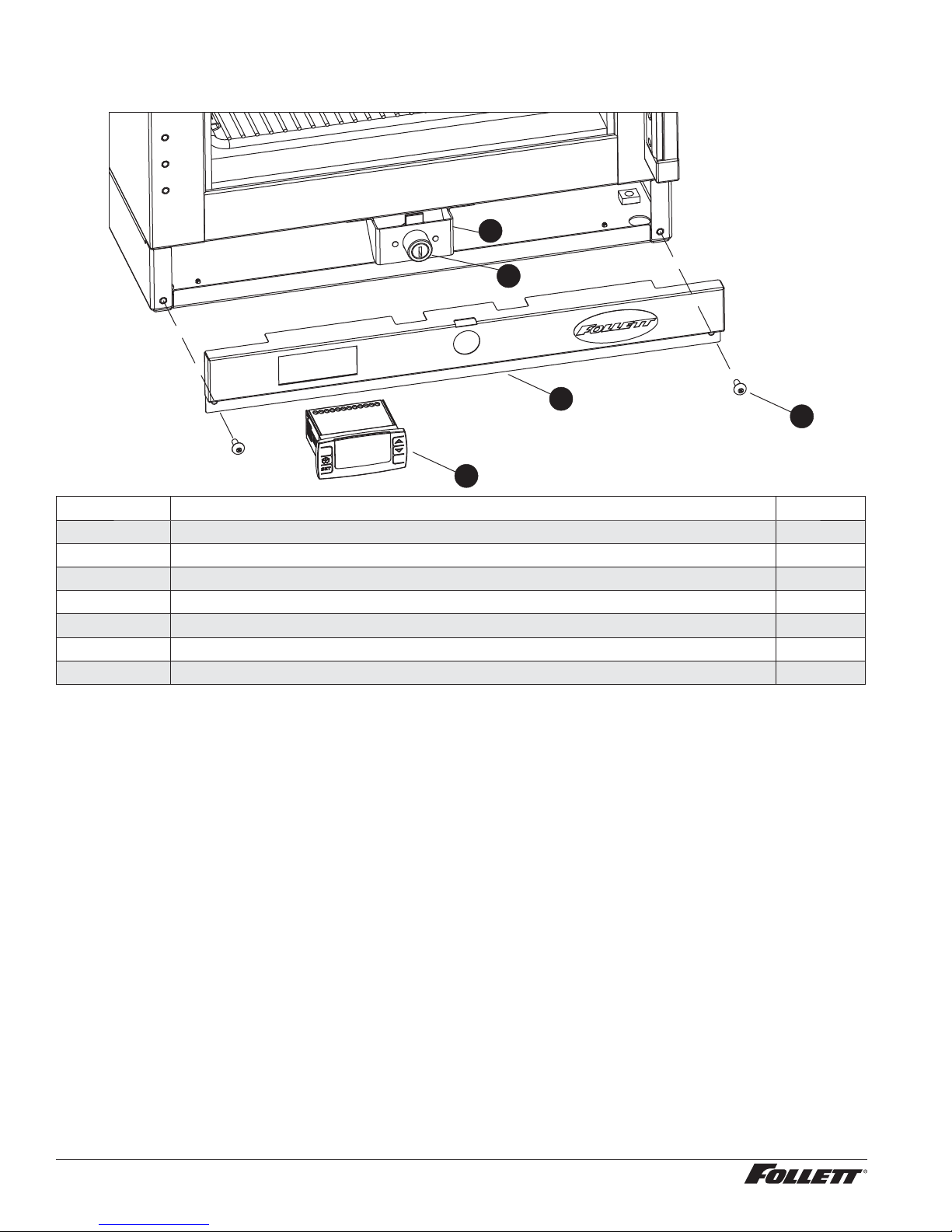
Replacement Parts –––––––––––––––––––––––––––––––––––––––––––––––––
Exterior Components
4
3
2
5
1
Reference Description Part #
1 Temperature Controller (must also order program key) 00959494
2 Panel, Front 00953208
3 Lock, Deadbolt (includes keys) 00959528
4 Bracket, Lock Mounting 00940619
5 Screw, Phil Truss HD, 10-32 x 1/2" 00105379
Not shown Program key, factory default settings 00967596
Not shown Foot pads 00900134
16 REF1/REF2 Compact Refrigerators
Page 17
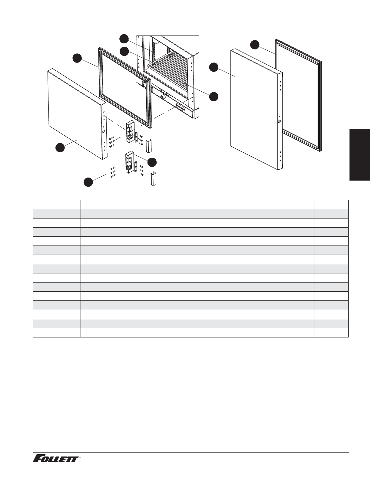
Door and Gasket Components
9
4
8
2
3
7
1
5
6
Reference Description Part #
1 Door, Assy, REF 1 00953182
2 Gasket/REF 1 00960823
3 Door, Assy, REF 2 00953174
4 Door Gasket / REF 2 00960831
5 Hinge, REF 1 and REF 2 00940478
6 Screw, Hinge - Pkg 6 00953190
7 Shelf 00960872
8 Support, Shelf, Snap tting 00156240
9 Support, Shelf, Pilaster 00105346
Not shown Lock Strike Bracket 00945790
Not shown Bottle, 60 ml 00112037
Not shown Gasket, REF, Alarm Bottle 00112029
Not shown Bottle, Bracket, REF 00961656
Not shown Glycerin 00959296
English
REF1/REF2 Compact Refrigerators 17
Page 18
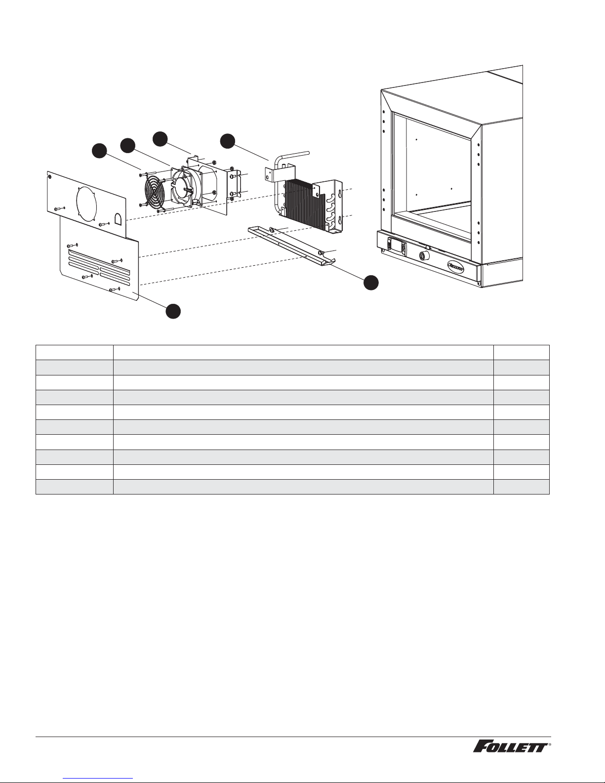
Evaporator and Motor
5
6
4
3
2
1
Reference Description Part #
1 Cover, Evaporator, REF 1 00958728
Not shown Cover, Evaporator, REF 2 00958975
2 Drain Pan, Evaporator, REF 1 and REF 2 00961037
3 Coil, Evaporator/Condenser, REF 1 and REF 2 00939835
4 Shroud, Evap Fan, REF 1 and REF 2 00958736
5 Motor, Fan 00940460
6 Guard, Fan 00940452
Not shown Probe, (note REF1 and REF2 use two probes each) 00155697
Not shown Bracket, Probe Guard 00980854
18 REF1/REF2 Compact Refrigerators
Page 19
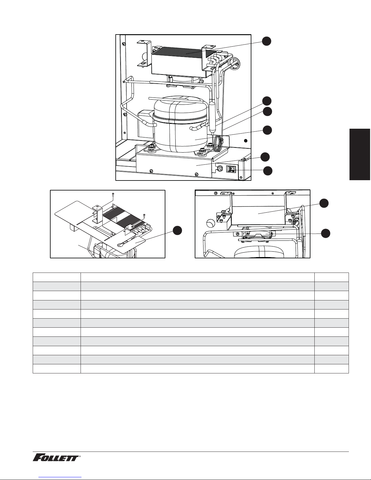
Compressor Components
6
5
4
1
English
2
3
8
7
Reference Description Part #
1 Compressor, REF 1 and REF 2 00959502
2 Bracket, Compressor Support, REF 1 and REF 2 00958694
3 Switch, Rocker, Recessed 00967604
4 Capillary Tube, REF 1 and REF 2 00959510
5 Filter/Drier 00961631
6 Coil, Evaporator/Condenser, REF 1 and REF 2 00939835
7 Baffle, Air 00965814
8 Shroud, Condenser Fan, REF 1 and REF 2 00958744
9 Motor, Fan 00940460
Not shown Cord, Power, NEMA 5-15 Hospital Grade 00961268
9
REF1/REF2 Compact Refrigerators 19
 Loading...