

Page 1
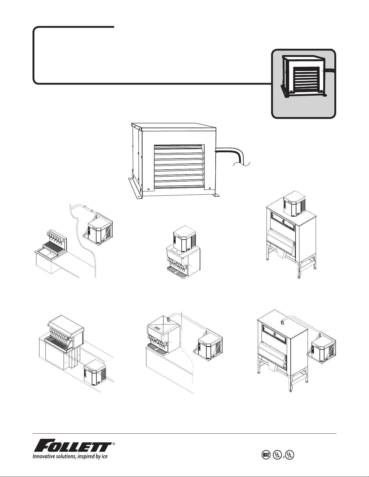
Horizon™ Ice Machine Installation Instructions
208264
Stock Module Identification Plate
Service No.
Module No.
Product
R
E
F
R
I
G
E
R
A
N
T
M
O
D
E
L
M
O
T
O
R
C
O
M
P
R
E
S
S
O
R
T
H
E
R
M
A
L
L
Y
P
R
O
T
E
C
T
E
D
E
a
s
t
o
n
P
e
n
n
sy
l
v
a
n
i
a
F
U
L
L
L
O
A
D
A
M
P
S
MAX
.
B
R
A
N
C
H
C
I
R
C
UI
T
F
U
S
E
S
I
Z
E
M
I
N
.
B
R
A
N
C
H
C
I
R
C
U
I
T
A
M
P
A
C
I
T
Y
D
E
S
I
G
N
P
R
E
S
S
U
R
E
H
I
G
H S
I
D
E
A
M
P
S
A
M
P
S
V
O
L
T
S
C
O
R
P
O
R
A
T
I
O
N
S
E
R
I
A
L
N
O
P
H
A
S
E
S
I
N
G
L
E
C
H
A
R
G
E
L
O
W
S
I
D
E
P
A
R
T
N
O
P
S
I
G
T
H
E
U
S
A
M
A
D
E
I
N
O
Z
R
C
R
H
Z
U
L
L
N
S
F
U
HCD/HMD/HCF/HMF1000R _ _
HCD/HMD/HCF/HMF1400R _ _
HCD/HMD/HCF/HMF1650R _ _
(See model number con gurator on page 2 for details.)
for Remote Condensing Unit
Order parts online
www.follettice.com
remote
condensing unit
a
i
n
va
l
y
s
n
n
e
P
O
n
N
o
t
T
s
E
a
L
AR
E
P
G
N
I
S
E
S
HA
P
Z
Z
O
H
O
N
N
L
TIO
G
I
A
S
RIA
R
P
E
S
O
E
RP
D
G
O
TE
C
S
AR
C
T
E
L
CH
O
OT
V
N
R
I
P
E
D
DE
Y
A
I
L
A
S
M
S
L
U
A
E
W
H
L
M
O
T
E
R
L
D
HE
F
O
T
S
M
R
N
O
S
S
E
S
R
P
M
U
L
MP
A
R
O
C
AD
R
O
O
L
L
C
OT
L
U
L
M
FU
R
S
P
M
E
T
A
ID
AN
S
R
H
E
G
G
I
PS
I
H
M
FR
A
E
E
R
R
U
S
S
E
R
P
Y
T
I
N
C
G
PA
I
S
M
A
E
T
I
D
CU
E
R
I
Z
I
C
S
H
E
S
C
U
N
F
A
T
R
I
B
U
.
IN
IRC
M
C
H
C
N
A
BR
.
X
A
M
208264
Stock Module Identification Plate
Module No.
Product
Service No.
O
N
T
R
E
L
A
P
G
IN
S
E
S
A
H
P
Z
O
HZ
G
I
S
P
E
G
R
HA
C
IN
E
E
D
A
A
SID
M
S
U
E
W
H
L
O
T
E
L
D
F
O
S
M
N
U
L
R
C
U
L
R
S
P
M
A
S
P
M
A
208264
Stock Module Identification Plate
Module No.
Product
Service No.
a
i
n
va
l
y
s
n
n
e
P
O
n
N
o
T
st
R
E
a
L
A
E
P
G
IN
S
E
S
A
H
P
Z
O
HZ
O
N
N
O
L
I
T
G
IA
I
S
R
RA
P
E
O
S
P
E
R
D
G
E
O
R
T
C
A
C
TS
E
L
H
T
C
O
V
N
RO
I
P
E
E
D
Y
A
L
A
SID
M
S
L
U
E
W
H
L
MA
O
T
E
R
L
E
D
H
F
O
T
S
M
R
N
O
S
S
S
RE
P
P
M
U
LL
M
A
R
O
D
C
A
R
O
O
L
T
L
C
O
U
UL
M
F
R
S
P
M
E
T
A
N
ID
A
S
R
E
S
GH
I
P
IG
R
H
M
F
A
E
E
R
R
SU
S
E
R
P
Y
T
I
N
C
A
G
P
I
S
M
A
E
T
I
D
U
C
E
R
I
Z
I
C
S
E
S
CH
FU
AN
T
R
I
B
U
.
C
N
I
R
I
M
C
H
C
N
A
R
B
.
X
A
M
208264
Stock Module Identification Plate
Module No.
Product
Service No.
Drop-in Remote Condensing
RIDE™ remote ice delivery
equipment
ia
n
a
v
l
y
s
n
n
e
P
O
N
on
t
T
s
R
E
a
L
A
E
P
G
N
I
S
E
S
A
H
P
Z
Z
O
H
O
N
N
L
IO
T
G
IA
I
A
R
R
PS
E
S
O
P
E
R
D
G
E
O
R
T
C
S
C
T
E
L
HA
T
C
O
O
V
N
R
I
P
E
E
D
Y
A
ID
L
A
S
M
S
L
U
A
E
W
H
L
M
O
T
E
R
L
E
D
H
F
O
T
M
R
NS
O
S
S
E
S
R
P
P
M
M
A
O
D
C
R
OA
O
L
T
L
O
L
U
M
F
S
P
M
E
T
A
D
N
I
A
H S
ER
S
G
P
RI
HIG
M
F
A
E
E
R
R
U
S
S
E
R
P
Y
T
I
N
C
A
G
P
I
S
M
A
E
T
I
D
U
C
E
R
I
Z
I
C
S
E
S
CH
U
N
F
A
T
R
I
B
.
CU
N
I
R
M
CI
CH
N
A
R
B
.
X
A
M
208264
Stock Module Identification Plate
Module No.
Product
Service No.
Vision™ Remote Condensing
RIDE remote ice delivery equipment
Harmony Remote Condensing
Top Mount
O
N
T
R
E
L
PA
G
N
I
S
E
S
A
H
P
Z
Z
O
H
G
I
S
P
E
G
R
A
H
C
N
I
E
E
D
D
A
I
A
S
M
S
U
E
W
H
L
O
T
E
L
D
F
O
S
M
N
U
LL
R
C
U
R
S
P
M
A
S
MP
A
208264
Stock Module Identification Plate
Module No.
Product
Service No.
Harmony™ Remote Condensing
RIDE remote ice delivery equipment
801 Church Lane • Easton, PA 18040, USA
Toll free (877) 612-5086 • +1 (610) 252-7301
www.follettice.com
Bin Remote Condensing
Top Mount
O
N
RT
A
P
Z
H
GE
R
A
H
C
E
D
I
S
W
L
O
L
DE
O
M
N
U
L
R
C
U
L
R
S
P
M
A
S
P
M
A
208264
Stock Module Identification Plate
Module No.
Product
Service No.
Bin Remote Condensing
RIDE remote ice delivery equipment
00160002R09
E
L
G
N
SI
E
S
A
H
P
Z
O
G
I
S
P
N
I
E
D
A
A
M
S
U
E
H
T
SF
Page 2
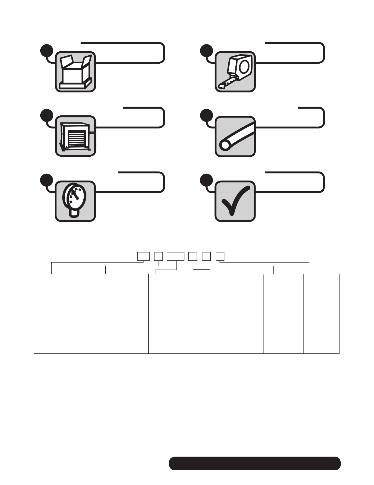
Read and complete the following 8 installation steps
Unpack
1
Condenser installation
3
Pressure adjustment
5
Site preparation
2
Refrigeration line assembly
4
Startup and test
6
MC Maestro™
Chewblet
(400 Series)
HC Horizon
Chewblet
(1000, 1400,
1650 Series)
HM Horizon
Micro Chewblet
C 208-230/60/1 (icemaking head)
®
Self-contained only.
D 115/60/1 (icemaking head)
Self-contained and remote. If remote
unit, high side is 208-230/60/1.
E 230/50/1 (icemaking head)
Self-contained only.
F 115/60/1 (icemaking head)
Remote only. High side is
208-230/60/3.
Chewblet® Ice Machine Model Number Configurations
HC 1400CSVA
CondenserSeriesVoltageIcemaker
400 up to
454 lbs
(206kg)
1000 up to
1036 lbs
(471kg)
1400 up to
1450 lbs
(658kg)
1650 up to
1580 lbs
(717kg)
A Air-cooled, self-contained
W Water-cooled, self-contained
R Air-cooled, remote condensing unit
N Air-cooled, no condensing unit for
connection to parallel rack system
V Vision™
H Harmony™
B Ice storage bin
J Drop-in
M Ice Manager
diverter valve
system
ConfigurationApplication
S RIDE™
(RIDE remote
ice delivery
equipment)
T Top-mount
2
REMOTE CONDENSING UNIT
Page 3
Carefully unpack and inspect the contents of your condensing unit
Site preparation
To ensure proper performance, ease of service and warranty coverage, it is
critical that you follow the requirements detailed in this manual. If you cannot
meet these requirements or have questions, call our technical service group
at 877.612.5086 for installation support.
Unpack
1
2
2.1
2.1
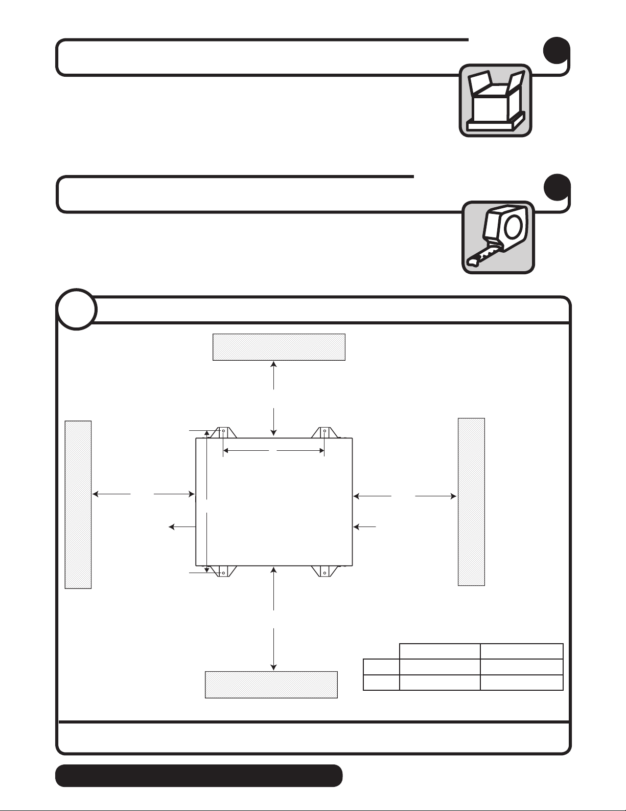
Condenser Unit Clearances
48"
(1219mm)
Discharge air
A
38" (965mm)
(only required for Single-phase units)
B
48"
(1219mm)
Air flow
48" (1219mm)
(only required for Single-phase units)
Single-phase 3-phase
A 27.0 (68.6 cm) 23.50” (59.7 cm)
B 38.9 (98.8 cm) 35.13” (89.2 cm)
• Position condenser unit as shown above, with clearances noted above
REMOTE CONDENSING UNIT
3
Page 4
2.1
2.2
Condenser installation speci cations
S-trap
required
P-trap
required
Easton Pennsylvania
CORPORATION
PART NO
SERIAL NO
MODEL
SINGLE
FULL LOAD AMPS
HZ
VOLTS
PHASE
MOTOR COMPRESSOR THERMALLY PROTECTED
OZ
CHARGE
REFRIGERANT
PSIG
DESIGN PRESSURE HIGH SIDE
LOW SIDE
208264
MIN. BRANCH CIRCUIT AMPACITY
AMPS
Stock Module Identification Plate
MADE IN
ULU
NSF
THE USA
L
RR
Module No.
MAX. BRANCH CIRCUIT FUSE SIZE
AMPS
C
Product
Service No.
EVAPORATOR
UNIT
➊
100' max.
(30,5m)
➍
EVAPORATOR UNIT LEVEL
CONDENSER UNIT
maximum
line rise
CONDENSER UNIT
CONDENSER UNIT
maximum
line drop
➋
+35'
(+10,7m)
+20'
(+6,1m)
+3'
(+0,9m)
–15'
(–4,6m)
100' max.
(30,5m)
➌
➍
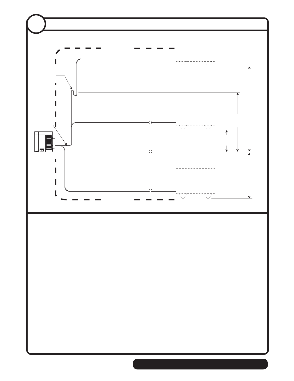
Site layout:
• Outdoor ambient temperature range: –20 F to 120 F (–29 C to 49 C)
• Installation with condenser unit elevations above 20' (6,1m) require an S-trap at the midpoint
of the rise
➊
• Maximum line rise must not exceed 35' (10,7m) ➋
• Maximum line set length must not exceed 100' (30,5m)
• Maximum line drop must not exceed 15' (4,6m)
➍
➌
Note: The service loop is not included when calculating the length, rise or drop
of the tubing run.
Note: 1400/1650 units only:
HCD1400/1650 condensing units contain a liquid to suction line heat exchanger. To maintain
optimum liquid refrigerant sub-cooling from the heat exchanger, the entire liquid line should
be insulated separately from the suction line.
4
REMOTE CONDENSING UNIT
Page 5
Condenser installation
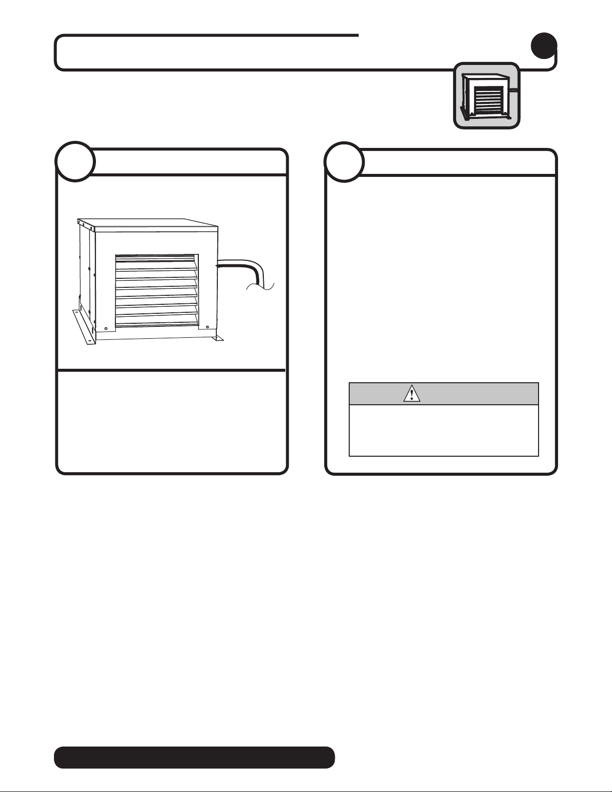
3
3.1
• Level unit
• Securely attach base of unit using holes
Install condensing unit
found in base plate
3.2
Horizon Remote Single-Phase
• 208-230/60/1
Horizon Remote 3-Phase
• 208-230/60/3
• Refer to wiring schematic located in
Electrical connections
1000 - 15 amp circuit
1400 - 30 amp circuit
1650 - 50 amp circuit
1000 - 15 amp circuit
1400 - 25 amp circuit
1650 - 35 amp circuit
condenser unit electrical box
CAUTION
• Electrical disconnects required within
10' (3m) for all hard wired connections
• Install in accordance with NEC and local
electrical codes
REMOTE CONDENSING UNIT
5
Page 6
Refrigeration line installation
4
4.1
Refrigeration line installation: 7/8" suction / 3/8" liquid line (1650)
5/8" suction / 3/8" liquid line (1000, 1400)
CAUTION
• The installer of the refrigeration line set must be USA Government Environmental Protection Agency (EPA)
certi ed in proper refrigeration handling and service procedures
• A quali ed person must perform all roof or wall penetration
• Do not form unwanted traps in refrigeration lines. A service loop is not considered an oil trap.
• Never coil excess refrigeration tubing
• The compressor oil rapidly absorbs moisture. Minimize the exposure of the refrigeration system by not releasing
the condenser unit or evaporator unit holding charge until all line connections are nished and the system is
ready for evacuation.
• It is recommended that both liquid and suction lines are run and insulated together for the rst 15 feet (4,6m)
from the condensing unit. This protects the system from sub-cooling loss and/or liquid slugging the compressor.
WARNING
• This unit contains an R404A holding charge
1. Make and connect line set run from the condensing unit to the evaporator unit with all
speci cations found in the installation speci cations section. Do not overheat shut off valves on
the condenser unit or evaporator unit.
2. Leak check eld joints via the evaporator unit service valves.
3. Evacuate line set via the evaporator unit service valves.
4. Determine required charge size based on the model and line length.
R404A Ice Machine Charge Speci cations
Line Run Charge 1000R Charge 1400R Charge 1650R
0 - 50 ft (0 - 15,2m) 8 lbs (4,9kg) 11 lbs (4,9kg) 11 lbs (4,9kg)
50 - 75 ft (15,2 - 22,9m) 9 lbs (5,4kg) 12 lbs (5,4kg) 12 lbs (5,4kg)
75 - 100 ft (22,9 - 30,5m) 10 lbs (5,9kg) 13 lbs (5,9kg) 13 lbs (5,9kg)
100 ft + (30,5m+) not recommended – consult factory
5. Open the liquid line service valve and suction line service valve on the evaporator unit and
condenser unit.
6. Open the liquid line valve on the receiver, then the suction line valve on the compressor unit.
7. Liquid charge unit through liquid line shut off valve on the evaporator unit or receiver valve on
the condensing unit.
8. Isolate the refrigerant tank from high pressure side on the system.
9. Turn on power to condensing unit and evaporator unit.
10. Complete system charge through low pressure side.
11. Insulate entire suction line including shut off valves to prevent condensation.
6
REMOTE CONDENSING UNIT
Page 7
Pressure adjustment
5
5.1
Check pressure adjustment
1. The pressure control is located in the electrical box near the refrigeration line set
connection point.
2. Verify the control is set for system operation of 10 psi cut out and 30 psi cut in
3. If adjustment is needed always adjust the cut in rst.
Start up and test
NOTICE
Ice machine MUST be cleaned and sanitized prior to operation!
Consult Operation and Service Manual provided with ice machine for cleaning and sanitizing instructions.
6.1
Verify operation
6
• Turn dispenser power ON if
applicable
• Check current draw of compressor
to verify correct electrical
operation
• Put a piece of ice on bin
thermostat or hold a cup under
the shuttle actuator on the bin/
dispenser to verify that the
evaporator unit shuts OFF;
condensing unit pumps down and
shuts off.
• After shut off, restart the ice
machine
Horizon Condenser Unit Compressor Amperage
Single-Phase
Model Number Compressor Running amps (+/- 10%)
1000R
00168054
1400R
00178640
1650R
00973925
3-Phase
Model Number Compressor Running amps (+/- 10%)
1000R
00990200
1400R
00990218
1650R
00990226
AJA7490ZXD 7.4
AWA9517ZXN 14.7
AVA9522ZXN 22.6
AWA9490ZXTHN 4.7
AWA9517ZXTHN 7.3
AVA9522ZXTHN 10.3
REMOTE CONDENSING UNIT
7
Page 8
Harmony, Horizon, Ice Manager, RIDE, and Vision are trademarks of Follett Corporation.
Chewblet and Follett are registered trademarks of Follett Corporation, registered in US.
801 Church Lane • Easton, PA 18040, USA
Toll free (877) 612-5086 • +1 (610) 252-7301
www.follettice.com
00160002R09
4/12
 Loading...