


K2 Power
Notice kits K2 Power
Congratulations on purchasing a
product from the range, K2 Power.
We are happy you share our
passion, for the “the Spirit of
Sound”. Designed using the latest
technology, these speakers con-
tinue Focals perfectionist beliefs,
developing products with high
power handling, and unrivalled
sound quality. To obtain the
best results from this product,
we recommend that you follow
carefully all the information
contained in this user’s manual.
If not followed correctly any fault
observed, may not be covered by
the guarantee.
Warning
Continued listening at high volume
levels above 110dB, are damage
your hearing durably. Listening above
130dB can damage your hearing
permently.
The Focal-JMlab guarantee
only applies if the enclosed
guarantee card is returned to
us within 10 days of purchase.
Information
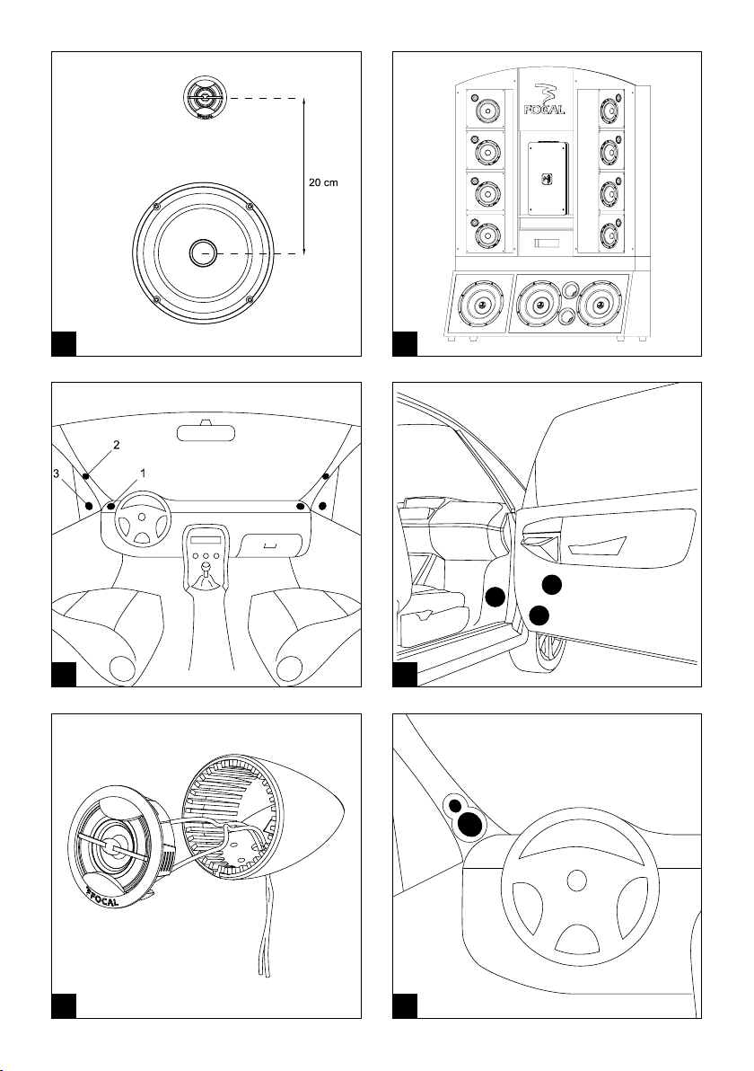
We make different measure types
on baffle plan of our speakers and
crossovers in order to guarantee the
best settings according to the placing
of your loudspeakers (fig. A). For a
use on a display shelf, we recommend
the crossover settings as follow:
tweeter level at 0dB, woofer in Flat
mode and filtering slope at 18dB/oct.
for the kits that have this function (fig.
B). For any installation in your vehicle,
please refer to the remainder of the
user manual.
Features
Membrane K2 Power:
New CMKV sandwich composite,
including (Aramid fiber, foam, and
structural glass fibre). Three individual
materials, each with their own
advantages, allow the cone to be
extremely rigid, with continued low
mass value, and increased damping
characteristics, even when played
loud. This ensures improved power
handling, with detailed sound quality,
low distortion even at high volume
levels.
Chassis made from Aluminum:
Inherently rigid and non magnetic.
Voice coil wound on Kapton former:
Light-weight and highly durable
material ensures no deformation of
voice coil.
Butyl moulded rubber surround
suspension:
Long life characteristics, even in the
most extreme climates.
TN53K with inverted tweeter dome:
Inverted dome formed in aramid fiber
material. Producing detailed high
frequencies, acoustically rich and
dynamic. Controlled with twin radius
wave guides, for totally controlled
staging and directivity.
Crossover of high precision:
Precise level adjustment of tweeter
and medium available. High
quality audiophile components
used throughout. Large wire gauge
connections included.
Focal-JMlab
®
- BP 374 - 108, rue de l'Avenir - 42353 La Talaudière cedex - France - www.focal-fr.com
Tél. (+33) 04 77 43 57 00 - Fax (+33) 04 77 37 65 87
Dans un but d'évolution, Focal-JMlab se réserve le droit de modifier les spécifications techniques de ses produits sans préavis. Images non contractuelles. ©Focal- JMlab
01
02
1
2
3
A B
C D
E
F

Tweeter
The TN 53k tweeter has been designed
for flush mount or surface mount
positioning, using the two fixing kits
provided. The choice of install position
is extremely important to deliver
the best performance and maintain
integration into the system. This is a
major factor for high frequency SPL,
and the the stability of the acoustics,
stereophonic imaging, and overall
staging. Please check the drawing to
understand this further.
The standard recommendation for
ideal stereo imaging, is to ensure the
tweeters “left” and “right”, are installed
in the same positions. Also they are
approximately at equal distance to the
driver (vice-versa for the passenger).
The various positions advised should
be verified and comparatives made,
for ideal positioning.
The tweeter should always be
positioned ahead of the normal
listening position. The main prefe-
rences are the outer positions of the
dash board (pic. C, 1), close to the
windshield (pic. C, 2). Normally easy
for installation. The location close to
the door mirror (pic. C, 3) is also
regarded as a good position, and
normally only requires a small amount
of install work.
Woofer-midrange
K2 Power woofer-midranges, posi-
tioned ideally high in the doors
(pic. D, 1), produce optimal midrange
frequencies, thus integrating better
into the rest of the system. If the
woofer-mids are positioned low in the
doors (pic. D, 2), the loss of midrange
can be compensated by adjusting the
crossover (see section “adjustment”
page 7-8).
The woofer-mids from the K2 Power
range can also be placed low in
the “kick-panels” (pic. D, 3) of the
vehicle. This is to further optimise the
stereophonic imaging.
Tweeter surface mounting
Two accessories are suggested for the
surface mounting of the tweeter.
The sole support, with a 30° angle (pic.
E) and the tweeter/woofer support that
has to be adapted to the windshield
upright through transformation (pic.
F). You can divide the box in 2 by
unsticking it or cutting it following the
central axis, this box is also reversible,
you just have to reverse the two flat
parts.
Fitted mounting
Cut out a 50mm diameter opening.
Make the tweeter wires go through.
Adjust the tweeter by pressing on the
side lobes (pic. G).
Attention: It is not necessary to twist
lock the TN53K in place using a
locking tool.To do so, carefully push
and turn on the outer radius wave
guides, turning the tweeter until it is
locked in place.
installation and positioning
03
04
0
-3
-6 dB
HG
JI
K L

05
Woofer and woofer-midrange
recommendations
K2 Power woofers and woofer-
midranges have been designed for
a multitude of vehicles installations.
It is worth understanding the basic
requirements for installing such
products. These woofers and woofer-
midranges are capable of delivering
enormous amounts of energy, during
their positive/negative movement.
Therefore it is imperative that they
be fixed rigid to the desired location.
The fixing location should also
be strengthened where necessary.
Panels should be strengthened to
eliminate any unwanted vibrations.
Such vibrations will drastically reduce
the overall performance. These drive
units should be fixed and sealed to
the baffle or location panel. The use
of the foam gasket is advisable for
correct air sealing.
For added performance, and to better
reduce such unwanted vibrations
and other acoustical losses, we
recommend the use of "plain chant".
Easily positioned behind the woofer,
on the metal-work of the vehicle, Plain
Chant soaks-up vibrations as well as
acoustic reflections.
Always ensure before that enough
space is available for the magnet
assembly, that it doesn’t interfere with
safety mechanisms or general working
parts.
In the case of not using the grilles
supplied, it is important to ensure the
speakers will fit correctly. Ensuring
there is enough depth behind the
speaker has already been explained,
but enough thought must also be
given for the forward movement of the
cone and surround assembly.
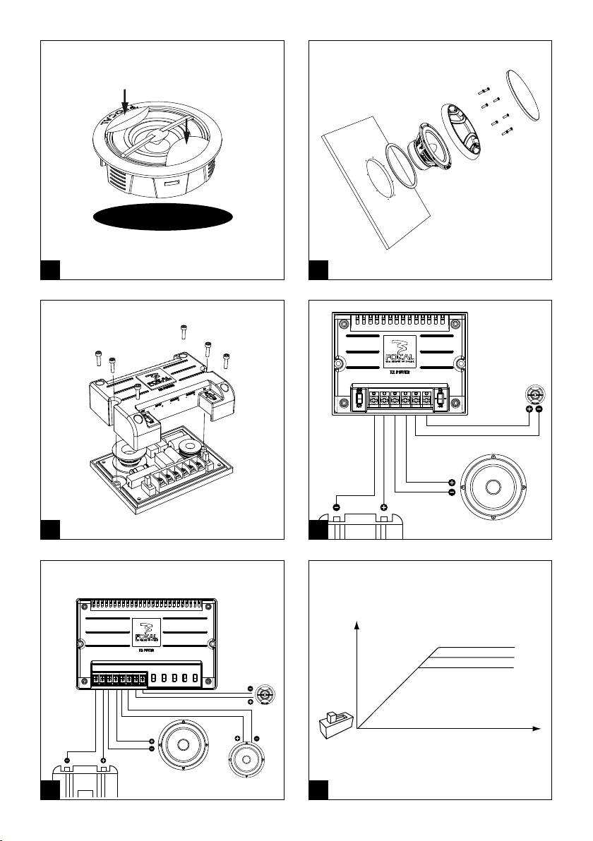
Woofer and woofer-midrange
If necessary, place the supplied screw
fixing clamps. Fix the round gasket
on the back of the woofer chassis.
Remove the metallic grille from the
rest of the grille. Make the grille holes
coincide with the ones of the driver,
fix with the supplied screws. Stack the
metallic grille (pic. H).
Crossover
To access some crossover settings, you
must remove the translucent cap with
the 4 screws (pic. I).
2-way kit wiring (165 KRX2 and
165 KRXS)
Plug the amplifier output on the “IN”
inputs of the crossover.
Connect the woofer on the “W” output
and the tweeter on the “T” (pic. J).
3-way kit wiring (165 KRX3)
Plug the amplifier output on the “IN”
inputs of the crossover.
Connect the woofer on the “Woofer”
output, the midrange on the “Mid”
output and the tweeter on the
“Tweeter” output (pic. K).
Finally always ensure the tweeter
and woofer are connected in phase
correctly, thus polarities are respected
“+” to “+”, and “-” to “-”. If not done
correctly a “hole” or “peak”, may
result, due to a shift in phase. This
will dramatically impair the overall
performance.
Installation and positioning
1
2
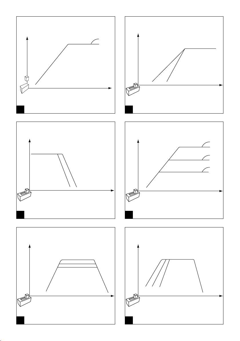
12 dB
Full
0 dB
-3 dB
-6 dB
12 dB
18 dB
1
+3 dB
1
0 dB
1
-3 dB
3
2
1
NM
PO
Q R
06
 Loading...