

Flytec 6040 GPS / TT34
Firmware Vers.2.05f 11.05.2009
Revision: 11.07.2011
Operation Manual


Operation Manual FLYTEC 6040 GPS
Table of contents
1 Operation .................................................................................................................................3
1.1 ......Instrument overview .......................................................................................................................3
1.2 ......6040-GPS –Switch-on and switch-off............................................................................................4
1.2.1 Switch On .................................................................................................................................4
1.2.2 Instrument Switch- off...............................................................................................................4
1.3 ......Operation philosophy ..................................................................................................................... 5
1.4 ......Keypad .............................................................................................................................................5
1.4.1 Function related key F1 and F2..............................................................................................5
1.5 ......Display screen.................................................................................................................................6
1.5.1 Main display screen..................................................................................................................6
1.5.1.1 Shift page of data fields........................................................................................................7
1.5.2 Map display screen...................................................................................................................8
1.6 ......„Windlayer“ Display Screen..........................................................................................................9
1.6.1.1 Shift page of data fields........................................................................................................9
1.6.1.2 Windlayer page ..................................................................................................................10
1.7 ......User defined data fields................................................................................................................11
1.8 ......The Setting menus ........................................................................................................................12
1.8.1 Menu navigation overview......................................................................................................12
1.8.1.1 User Settings......................................................................................................................13
1.8.1.2 Manage Memory ................................................................................................................13
1.8.1.3 Instrument Settings ............................................................................................................14
1.8.1.4 Factory settings..................................................................................................................14
1.8.1.5 Flight Memory and Data analysis.......................................................................................15
1.8.2 Entering Text ..........................................................................................................................15
1.9 ......First steps ......................................................................................................................................16
1.9.1 Before first balloon flight Seite..............................................................................................16
1.9.2 At start site..............................................................................................................................16
1.9.3 Handling during the balloon flight ...........................................................................................16
1.9.4 Data analysis after the balloon flight ......................................................................................16
2 Functions ............................................................................................................................... 17
2.1 ......Altimeter and air pressure............................................................................................................17
2.1.1 How does an altimeter work? .................................................................................................17
2.1.2 Altimeter Alt1 (absolute Altitude) ............................................................................................18
2.1.2.1 Setting altimeter A1............................................................................................................18
2.1.2.2 User fields related to Alt1 ...................................................................................................18
2.1.3 Altimeter Alt2, Relative Altitude (User field) ...........................................................................19
2.1.3.1 Setting Altimeter Alt2..........................................................................................................19
2.1.4 Cumulated Altimeter display (User field Alt Sum) ..................................................................19
2.1.5 FL Flightlevel Altimeter display (User field FL ft)....................................................................19
2.1.6 GPS Altitude display (User field Altitude GPS) .....................................................................19
2.1.7 Altitude Alert / Alarm...............................................................................................................20
2.1.7.1 Setting of the altitude alert .................................................................................................20
2.2 ......Variometer functions ....................................................................................................................21
2.2.1 Analogue Vario .......................................................................................................................21
2.2.1.1 Basic filter...........................................................................................................................21
2.2.2 Digital-Vario (Average Vario)................................................................................................21
2.2.3 Variometer Acoustics and Volume level (Sound)...................................................................21
2.2.3.1 Audio Level ........................................................................................................................22
2.2.3.2 Variometer Acoustic Settings .............................................................................................22
2.3 ......Speed..............................................................................................................................................23
2.3.1 Wind vane sensor...................................................................................................................23
2.3.2 GPS Speed.............................................................................................................................23
2.4 ......Time of day and date ....................................................................................................................23
2.5 ......Temperature ..................................................................................................................................24
2.6 ......Envelope Temperature .................................................................................................................24
2.6.1.1 Personal temperature alarm...............................................................................................24
2.6.1.2 Maximum Temperature Alarm............................................................................................25
2.6.1.3 Temperature sensor failure ................................................................................................25
2.6.1.4 TempRx Empfang On/Off...................................................................................................25
2.7 ......Temperature transmitter FLYTEC TT34 ......................................................................................25

Operation Manual FLYTEC 6040 GPS 2
3 Navigation .............................................................................................................................. 26
3.1 ......Assesment of GPS Reception quality.........................................................................................26
3.2 ......Compass and flight direction.......................................................................................................27
3.2.1 Track and Bearing ..................................................................................................................27
3.3 ......Waypoints and Coordinates.........................................................................................................28
3.3.1 Alter, delete or insert waypoints .............................................................................................28
3.3.2 Display of actual coordinates .................................................................................................29
3.3.3 Memorising the actual position...............................................................................................29
3.3.4 Go-To – Function....................................................................................................................30
3.3.5 Distance to Waypoint (User Datafield) ...................................................................................30
3.4 ......Routes ............................................................................................................................................30
3.4.1 Creating a Route ....................................................................................................................31
3.4.2 Altering a Route......................................................................................................................31
3.4.3 Deleting a Route.....................................................................................................................31
3.4.4 Flying Routes..........................................................................................................................32
3.4.4.1 Distance to Start Site .........................................................................................................32
3.4.4.2 XT Error, Crosstrack Error ..............................................................................................33
3.4.5 Flight duration.........................................................................................................................33
4 Map of Flight Obstacles (Restricted areas)......................................................................... 34
4.1 ......Flight obstacles – Edit manually .................................................................................................34
4.2 ......Map of flight obstacles - Edit with Flychart...............................................................................36
4.2.1 Air Space in OpenAir Format *.txt or *.fas..............................................................................36
4.2.2 Calling the function Air Space in Flychart ..............................................................................36
4.2.2.1 Downloading Air Spaces ....................................................................................................37
4.2.2.2 User Air Spaces ending with *.fa5 .....................................................................................37
4.2.2.3 Selection of Air Spaces ......................................................................................................37
4.2.2.4 Editing Air Spaces..............................................................................................................38
5 Flight-Memory and Flight-Analysis...................................................................................... 40
5.1.1 Flight logbook and Flight-Analysis page ................................................................................40
5.1.2 Graphic display of Flights in Map format................................................................................41
6 Data transfer .......................................................................................................................... 42
6.1 ......Data exchange via PC ...................................................................................................................42
6.1.1 Waypoints and Routes ...........................................................................................................43
6.1.2 Air Spaces ..............................................................................................................................43
7 Simulation .............................................................................................................................. 43
8 Battery- Management............................................................................................................ 44
9 Transferring new software-(-firmware)to the Flytec 6040-GPS......................................... 45
10 Miscellaneous........................................................................................................................46
10.1 ....Optional Software (additional Software)...................................................................................46
11 Additional Information ..........................................................................................................47
11.1 ....Altimeter.........................................................................................................................................47
11.2 ....Navigation......................................................................................................................................47
11.2.1 Reception quality of GPS .......................................................................................................47
11.2.2 Accuracy of GPS Altitude .......................................................................................................48
11.3 ....Flight Memory and IGC File..........................................................................................................50
11.3.1 Content of IGC File.................................................................................................................50
11.3.2 Evidence of flights – Security against manipulation...............................................................52
11.3.3 Digital Signature -...................................................................................................................52
12 Maintenance........................................................................................................................... 53
12.1.1 Exposure to Water..................................................................................................................53
13 Warranty.................................................................................................................................53
14 Technical Data ....................................................................................................................... 54
15 Approval / Conformity........................................................................................................... 54
16 Attachment............................................................................................................................. 55
16.1.1 Mounting instruction for the Radio Temperatur Transmission Unit Funksensor TT34 ..........55
Operation Manual FLYTEC 6040 GPS 3
1 Operation
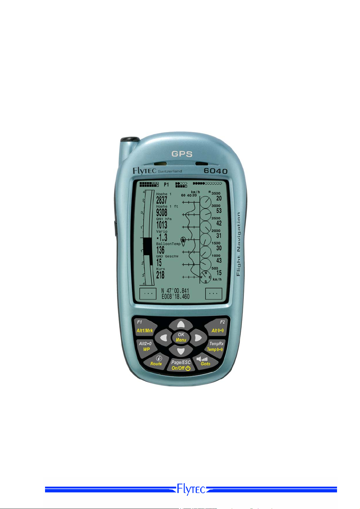
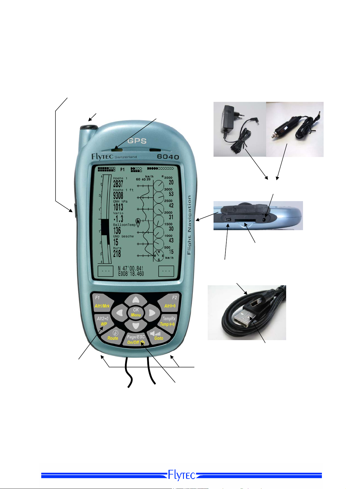
1.1 Instrument overview
Connection jack for wind
vane sensor (option)
Antenna TT34 Receiver
Key Pad
Safety Cord
Loudspeaker
On / Off
switch key
Charging set
110-230 V/AC
Cover right side
USB Mini B
chargin LED’s
Veh. Charge
cable 12V DC
Charger Jack
SD Card Slot
USB Plug
PC side

Operation Manual FLYTEC 6040 GPS 4
f
1.2 6040-GPS –Switch-on and switch-off
1.2.1 Switch On
Init EEPROM
English ↑
Deutsch
Francais
Espagñol
Italiano
Magyar ↓
---------------------------------
OK
FlyTEC AG
6040
Sn
8642
TT34 Adress: 6475
Owner: not set
Balloon Typ: not set
V ersion 3. 02 16.05.08
Date
T ime(U T C)
12.06.09
ba t t e r y c h e c k
a t t e r y B a n k 1 : 8 8 %
B
B a t t e r y B a n k 2 : 9 0 %
13:29
o r 3 s..
1.2.2 Instrument Switch- off
Bat Bank 1: xx %
Bat Bank 2: xx %
switch off ?
Ausschalten?
Arrêter ?
Press Ok
Drücke OK
Appuyer sur OK
The instrument is switched-on by pressing the On/Off key.
By use of the ▲ or ▼ keys the required language may be selected.
The language as selected shall automatically be enabled again upon
next switch-on
After confirmation, the idsplay switches for 15 sec to the switch-on
Display with the following information:
- Type of instrument and serial number
- Software (Firmware) Version
- Time, Date
- Battery Status
For switch-off press the On/Off key as long until the question:
Switch-off?
Press OK
Is prompted on the screen.
Again, to prevent unintentional switch-off, also this action needs to
be acknowledged by pressing the OK key !
1. Following OK acknowledgement the instrument is immediately
switched-off, in case no flight recording has been made.
2. Following an active flight recording, the readout screen Flight -
Analysis is displayed before switch-off. If you want to quit the
flight analysis display, press shortly the OK or ON/OFF key,
the instrument will then be switched-off immediately.

Operation Manual FLYTEC 6040 GPS 5
y
1.3 Operation philosophy
- white key lettering: all acoustic signal settings, the F1 / F2 key commands, the display screen shifts
and an information request (
i) , can be made rapidly during the flight by short pressure
on the key.
- yellow key lettering: by long pressure of 3 sec. important functions may be called up directly during
the flight and may also be edited. The selected function remains active, until another function will be
called up!
- Main menu: all instrument settings, but also Waypoints- Routes- and Flight obstacle- editing,
can be set before the flight via the Main menu (MENU key).
Tip: all instrument settings of the Main menu can be set comfortably by use of the freebie PCSoftware Flychart on the PC and be transferred via USB-interface onto the instrument.
1.4 Keypad
Functions of F1 key
Selection for revision of user
Alt 1
1013
Defined fields
Setting alttude A1
Insert Marker during flight
into flight recording
Altitude A2 set to 0
Selection of waypoints
within a route
Info Key Display of
current coordinates and
information
Route selection
Display shift / in menu 1 setp backward
On/off ke
1.4.1 Function related key F1 and F2
Both keys F1 and F2 alter their setting possibilities acording to their functios or display. The
Signification of the keys is always shown on the right and left side of the bottom of the display.
.
Example: On the map screen the F1 key is related to the function „“Zoom Out“ and the function
“Zoom in” is related to the F2 key, whil in the set-mode waypoints the function related to the F1
key is_”Add waypoints” and “Delete waypoints” for the F2 key.
Alt1
GPS
Funcitons of F2 key
Shifting the user defined
pages
Setting altitude alert
Acknowledgement key OK
Instrument Main menu
Wireless Temperatur Transmission
TT34 key
Function Menu
Audio Sound level
WP-Selection
Operation Manual FLYTEC 6040 GPS 6
V
A
013
0
0 0
3
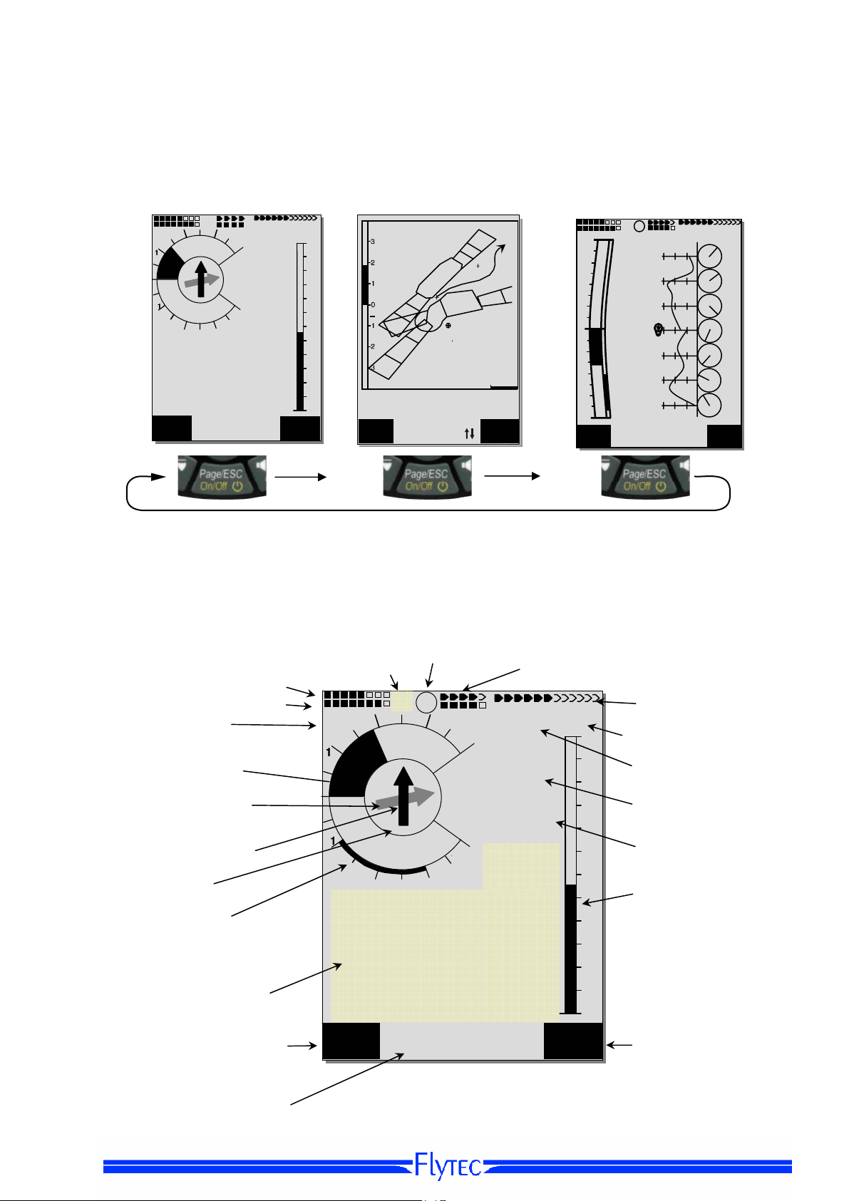
1.5 Display screen
The 6040 instrument offers three different display screens. After the switch-on display screen, the
main display screen is automatically displayed
.
Main display sreen Map display screen Windlayer display screen
m/s
Alt
1013
After short pressure on the page-key the display screen can be shifted.
1.5.1 Main display screen
Battery charge bank 1
bank 2
Vario Unitt
Analogue Vario
Direction to next but
One WP
Direction to WP
Compass
Sink Audio ?
Alarm-level ?
User selectable
Data fields
Function of F1 key
P1
3
2
N
E
W
S
2
3
EnvTemp
81.6
Time
10:35
Mod Alt 1 uv
Infoline 1
Infoline 2
Km/h
Int
1.4
QNH
28
60
50
40
30
20
10
0
Alti
Gps
4
m
2816
4
1013
Kurs
45
Flugzeit
1:25
Data fiels page number
m/s
EnvelTemp
86.2
Uhrzeit
18:45
Alt 1
- - -
1013
+
ario
1.9
Zoom
Out
2
N
Start
Stanserhorn
ltitude
Speed
1248 16
CTR Buochs
Mod Alt1
Aktive Information
P1
i
3
E
SW
2
3
Mod Alt 1 uv
Zug
10
EnvelTemp
81.6
Zoom
In
km/h
m/s
1.8
2816
4
QNH hPa
101
Kurs
45
Flugzeit
1:26
4
3
2
1
m/s
Hoehe1
2018
QNH hPa
1013
Huellen Temp
60
40
km/h
20
81.6
1
Kurs
2
23
3
Gnd Geschw
4
31
Alt 1
---
1
Temperatursender Empfang
Temperatursender Batteriestatus
GPS
Number of satelites
28
Digital Speed Anzeige
60
Speed Unit
50
Digital Vario Display
40
Altitude
30
GND Speed
2
1
Alt 1
GPS
Function of F2 key
Alt1
3500
18
3000
50
2500
45
2000
13
1500
30
1000
42
500
15
Operation Manual FLYTEC 6040 GPS 7
5
A
5
A
A
8
5
6
6
A
A
User defined data fields
There are 7 data fields in the lower part of the display which may be allocated individually.
In total more than 20 selectable data fields are at disposal. For list of data fields please refer
to 1.7 - User defined data fields page 10. (depending on firmware version!)
Alter data fields manually
Mark by repeated pressing of the ◄ arrow key the data field to be altered. The selected data field
shall be designated by a black bar. By use of the ▲ or ▼ arrow keys it is possible to assign
a new readout value to the selected data field. The field designation is displayed at the same time in big
lettering in Infoline 1.
If nothing is changed after having selected a field, the instrument returns to normal function after 10
sec. and the previous display is shown again
Alter data fields on the PC
All user defined readouts can be set comfortably by use of the freebie PC-Software Flychart on the PC
lt
2
N
W
2
Time
16:0
FltTime
2:4
Temp
P1
3
4
E
S
m
2816
4
1165
3
GLZGrund
8.
GndGesch
1
Mod Alt 1 uv
Km/h
Int
-2.5
m/s
lt 2
Wind
12
56
1013
57
90
80
2
70
N
60
S
W
50
40
2
3
Kurs
30
42
lti
Peilung WP
Gps
2:4
Dist WP
12 . 4
lt
Mod Alt 1 uv
P2
3
E
Abw SpurW
Km/h
4
Int
-2.5
m
2816
Alt 2
4
1165
m/s
0.6
GLZ Soll
12
GLZ Grund
10.5
Alt
1013
57
90
80
70
60
2
50
N
40
W
30
Alti
2
Gps
Dist Ziel
9.4
GLZ Gnd
11.2
!
P3
3
4
E
-2.5
S
m
2816
Diffgeschw
4
14
3
Abw BGZ iel
6
GLZ Ziel
10.5
Mod Alt 1 uv
Km/h
Int
57
lti
Gps
90
80
70
60
50
40
30
and be transferred via USB-interface onto the instrument
Caution: for safety reasons it is not possible to alter the user selectable fields during the flight
1.5.1.1 Shift page of data fields
The seven data fields exist 3 times on each page of data field! Therefore you have the possibility to
configure in total 21 data fields individually!
The very same function is also available on
the windlayer display page
!
Short pressing of the right side arrow key
gives access to the next page. The page
m/s
number is shown in the upper part of the
display next to the battery-charge state
readout as P1, P2 or P3.
In -> Main Setup Menu -> Instr. settings ->
User fields it is possible to configure these
readout pages with 4 big or 6 small fields !
We would like to present to the user some
proven recommendations in regard to the
default values of the 3 adjustable pages.
Some of the readouts are of such interest
1013
that we recommend to keep them on each
of the 3 possible pages always at the same
position. For example: the “Speed over
ground - Gnd-Speed” or the wind
component “Speed diff.”
Example:
page 1) General Flight information is called up before the start or when the pilot is currently
in a normal balloon flight.
page 2) Navigation page is used if a Waypoint (WP) has been selected as goal to fly to.
Instead of the values recommended above, this field should mainly contain navigation readouts, such
as “Dist. to WP”, “Alt. a. BG”,; “Alt. a. WP”.
page 3) General information with altitude Alerter Here the pilot can configure the6 field-display. The
two new Data-fields can be used to display the upper and lower Altitude alert Level. The most important
data fields such as ONH and Envelop Temp, should also be present on this page.
Operation Manual FLYTEC 6040 GPS 8
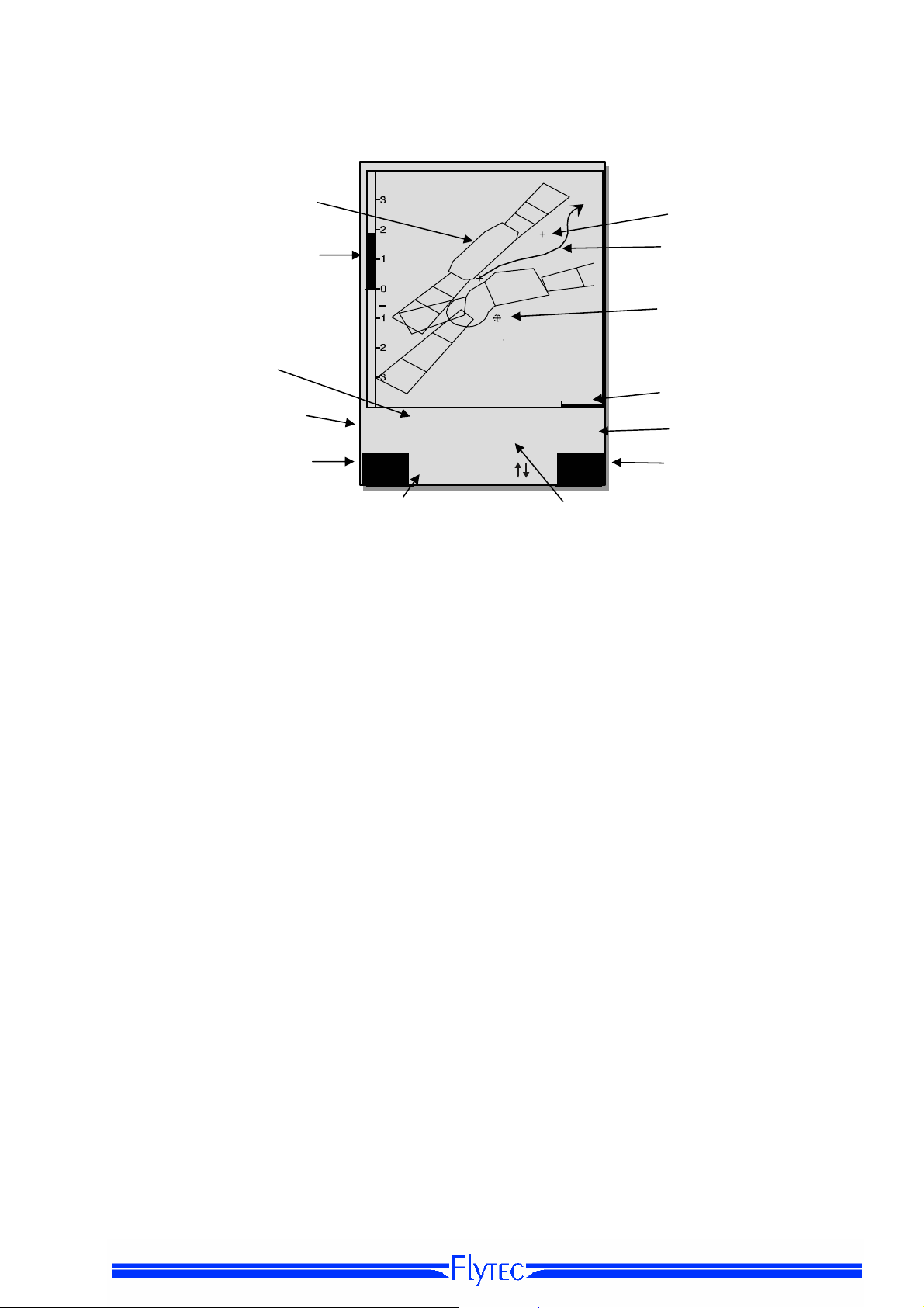
1.5.2 Map display screen
Air space
Analogue
Variometer display
+
Start
Stanserhorn
Zug
Altimeter
10
Digital variometer
Vario
1.9
Function of F1 key Function of F2 key
Information lines
Zoom
Out
Altitude
Speed
2486
CTR Buochs
Mod Alt1
16
EnvelTemp
82.6
Zoom
In
GND Speed
By short pressing on the „page“ key the map format page is selected. (North is always at the top!)
The map mode display screen illustrates the current track. In addition, Air space data such as
TMA, CTR, Wildlife protected areas and stored Waypoints with cross and its name are displayed.
In case of active COMPETITION Route, the start and Waypoint cylinder as well as Waypoint
interconnections of the Route are also displayed.
This screen also displays the flight relevant data such as analogue Vario, altimeter, speed and
Digital-Vario.
By using the two function keys F1 and F2 you can magnify or also scale down the map segment.
The map scale is shown in the lower part on right side.
F1: Zoom out: the map scale is gradually decreased until the total map overview is achieved.
F2: Zoom in: the map scale is gradually magnified, therewith individual details of the
recording are clearly recognisable !
OK: from each graph back to the screen optimised graph.
Info i: Information related to the next three flight obstacles shall be shown.
Page: return to main screen page.
All other keys cause the Track in the current selection to be redrawn.
Arrow keys:
By using the right side arrow key, you can fade out all Waypoints not being part of the Route
during the flight. For any new map-/screen graph selection, all Waypoints are always shown.
During the flight the active position is in the centre. The display screen is scrolling by half
when the active position has reached the map border, or if one returns from another readout screen to
map mode.
.
hen viewing a stored flight in the Flight Memory, and using the arrow keys, the illustrated area can be
shifted up, down, left or right. However, this function is not enabled during an actual flight.
Waypoint
Track
Waypoint with cylinder
Scale
Envelope Temp
Operation Manual FLYTEC 6040 GPS 9
y
i
p
Remark: any screen layout may take a few seconds according to the relevant data volume.
The more Trackpoints are already stored in memory, the more time is required for the completion of
screen layout. If a zoom or pan key is activated during the screen layout, the momentary layout process
will be stopped and will resume with the new values. Thus one can obtain the desired graph rapidly.
The Track is plotted back from the active position. This may be important for the screen layout
during very long flights and short recording intervals.
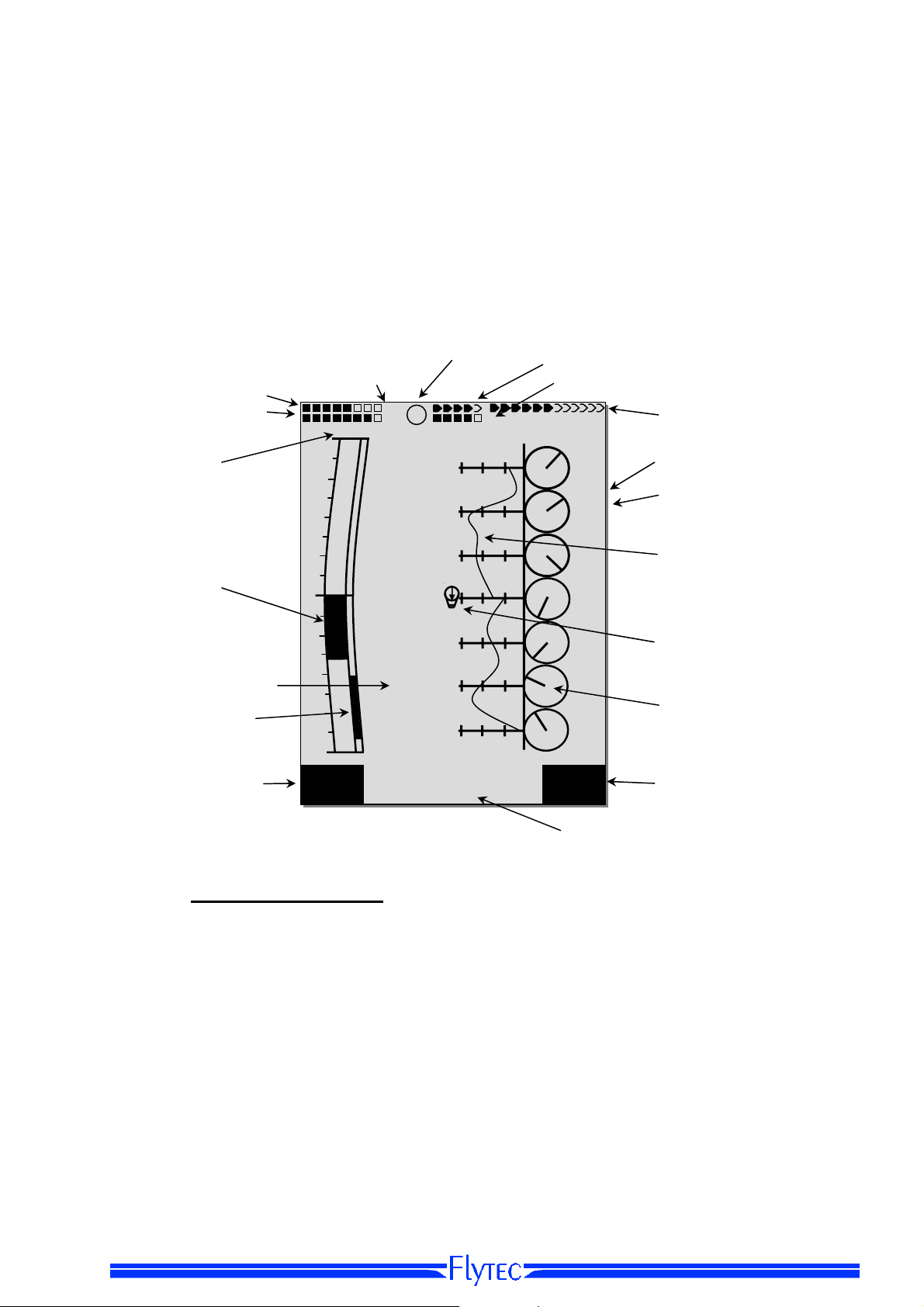
1.6 „Windlayer“ Display Screen
After a short pressure of the page-key, the windlayer display screen will be displayed just after the
map displiay screen.
Status battery bank 1
Status battery bank 2
Vario Unitt
Data field page number
4
3
P1
Hoehe1 m
2018
QNH hPa
Huellen Tem
85.2
- - -
1013
Kurs
16
Gnd Geschw
31
Mod Alt 1 uv
Analogue Vario
User selectable Datafileds
Sink audio Alarm
Treshold
Function of F1 key
2
1
1
2
3
4
Alt 1
1013
1.6.1.1 Shift page of data fields
The seven data fields exist 3 times on each page of data field! Therefore you have the possibility to
configure in total 21 data fields individually!
Short pressing of the right side arrow key gives access to the next page. The page number is shown
in the upper part of the display next to the battery-charge state readout as P1, P2 or P3.
See list of the data fields under 1.7. User defiended datafields page 10(depends on the version of
the firmware)
Tipp: This function is also available on the main display screen.
Aktive Information
km/h
40
20
60
TT34 Receiption of envelop temp
Status battery of temp receiver
number of GPS
satelitesf
3500
18
3000
Altutde of the
ers
windla
Wind Speed
50
2500
45
2000
Curve indicating
31
1500
30
1000
Actual altitude / position
42
500
Compass Wind direction mp
15
Alt1
GPS
IInformation lines
Function of F2 key
.

Operation Manual FLYTEC 6040 GPS 10
6
W
1.6.1.2 Windlayer page
Ascent phase
After switch on, befor start, the scale is at its maximum of
100 m resolution. The start point is always between the
two lowest scale units. When the top margin is reached
the whole scale will be shifted down by one scale unit
Example: Start 530m Æ Ascent up to 840m
Descant phase
During descant th old values from the ascent phase
will be overwritten with the new data
Windlayer scale Zoom and Scroll
After entering the windlayer page F1 and F2 are
prest with Zoom and Scroll function. A brief
keypress activates the function. The activated
function is visible in the information display
Zoom Function
With the up and down arrow the zoomfcator for
the scale can be chosen. There ar 4 zoom steps
(100m - 200m - 500m - 1000m). After entering a
new zoom display. the actual position is between
th
the 4
and the 5th scale unit.
Scroll Function
The windlyer scale can be shifted with the up and
down arrow key.
Hint:
A long keypress on Alt1 activates the
altitude adjustement function for about 10
seconds. The function keys F1/F2 will
show the available functions
m
1100
1000
900
800
700
N
500
W
E
S
Alt1
GPS
m
3500
18
3000
50
2500
45
2000
31
1500
30
1000
42
N
500
W
E
15
S
Alt1
GPS
Zoom uv
km/h
40
60
Alt 1 uv
1
2
3
4
Zoom
- - -
40
20
km/h
40
40
20
60
Alt 1 uv
Kurs
1
Gnd Geschw
31
20
W
N
E
S
Scrol
N
E
S
Alt1
GPS
1500
1000
500
m
1100
900
800
31
700
30
600
500

Operation Manual FLYTEC 6040 GPS 11
1.7 User defined data fields
The main display page contains 3 pages each which are stepped forward by using the ► key.
Thus it is possible to display almost all of the following measuring values in the right context.
The page number is shown next to the battery-charge state readout as P1 .. P3.
page
displlay remains empty
Time Time of day 23
Flight time Flight time since take-off 40
Vario Digital Vario 21
Altitude 1 m Absolute altitude 18
Altitude 1 ft Absolute altitude in ft 18
Altitude 2 Reference altitude, may be set to 0 user-defined 19
GPS altitude GPS altitude 19
Altitude 3 Sum Cumulated gain in height during the flight 19
FL (ft) Flight level in feet. Not alterable 18
QNH hPa Air pressure in Hektopascal 18
QNH inHg Air pressure in inch of Mercury 18
Gnd Speed Speed over Ground * ( = GS) 23
Air Speed Vane wheel sensor air speed (Option)
Track Flight direction (Course)*
Bearing WP Direction to selected Waypoint *
CrossTrack Error Perpendicular distance to the active leg of a route 33
Dist WP Distance to selected Waypoint *
Dist t End Distance to end of route
Dist Start Distance from take-off position
Dist Cyl Distance to WP cylinder
Dist CTR Distance to next Air space 34
Up Alert Upper Altitude Alert
Low Alert Lower Altitude Alert
Temperatur Instrument Temperature
Env. Temp Envelope Temperature
Max. Env. Max. Envelope Temperature
SMS p/t Number of SMS Pending/transmitted (option)
If nothing is changed after having selected a field, the instrument returns to normal function
after 10 sec. and the previous display is shown again.
23
27
27
30
31
32
30
20
20
23
24
25
46

Operation Manual FLYTEC 6040 GPS 12
1.8 The Setting menus
Long pressure on the MENU key gives access to setting mode. By use of ▼ and ▲ keys one
of the Menu items is selected and by pressing the OK key access is given to the corresponding
subdirectory.
1.8.1 Menu navigation overview
page
Flight memory 40
Waypoints
Routes
Air space
>User Settings
>
Manage Memory
Simulation
>Instrument Settings
34
>Variometer
Basic filter 21
Digital Vario Integrator 21
Sink Alarm
>Variometer Acoustics
Acoustic settings 21
Threshold Sinktone 21
>Speed
Speed Scale
Setting wind vane 23
>Flight Memory
Recording Auto/Man
Recording interval
Envelope Temperatur
Pilot’s name
Type of aircraft
Aircraft ID
Delete flights 12
Delete WP&Routes 12
Formatting Memory 12
Delete Airspace 12
43
Display contrast
TT34 Number
Battery type 44
Time zone 23
Units
Coordinates format
Pressure sensor Corr
User Filds
Language
Bluetooth Option
SMS Option
>Opt.Software 46
>Factory settings
15
28
30
23
40
15
24
15
15
14
24
14
14
14
11
14
Operation Manual FLYTEC 6040 GPS 13
1.8.1.1 User Settings
A series of settings allow the instrument to be programmed in accordance to the user’s wishes. Every
pilot may realise his very own ideas here. All the basic settings may be set comfortably
on the PC by use of the PC-Software „Flychart“ and be transferred later to the instrument via the
PC interface.
In most cases the possible setting range and its previously valid value is indicated individually for each
of the settings. If this value should be modified, pressing on the OK key gives access to change mode,
the value to be modified will blink and can now be altered by use of the ▼ and ▲ arrow keys. Pressing
the OK key confirms the new value, pressing of the ESC key recalls the previous setting.
Term Denotation more Factory Settings
Variometer
Basic filter Diagnose time constant f Vario and
Acoustics settings Sink tone-freequency, 22 800 Hz
Sink tone Threshold Activation point of sink tone 22 2 m/s (ft/min.)
Activation point of sink alarm 22 4 m/s (ft/min.)
Speed
Analog Scale Scale 23
info
21 2
Speed
Sensro setting wind
Correction wind vane 70 ... 150 % 23 100 %
vane
Flight memory
Recording Auto/Man Autom. or manual Flight recording 40 Aut.
Recording intervall Time interval per recording point- 2 to
40 10 Sec
30 seconds.
Envelope temp. Alarm
Pilot`s name
Alarm Range 70-130 °C
Entry of pilot`s name max. 25
24 100°C
15 not set
characters
Type of balloon
Balloon ID
Type , name of the balloon for IGC
Identity number of the balloon for IGC
15 not set
15 not set
1.8.1.2 Manage Memory
Deelet flights Deleting the entire flight memory. This
command reformats the flight memory,
although the other settings are not lost.
Delete
WP & Route
Formatting memory Reset of Basic values to factory settings 40 No
Delete Air space Reorganisation of the Memory zone for the
Caution: when deleting WP, Routes or flights the deletion process will take a couple of seconds, please
wait during this time span.
Deleting all WP’s and Routes 28 No
Restricted Areas (CTR’s)
40 No
34 No

Operation Manual FLYTEC 6040 GPS 14
1.8.1.3 Instrument Settings
Term Denotation more Factory setting
Info
Display contrast Range 0.. 100 % - 50 %
TT34 Number Serial nb. Temperatur transitter 24
Battery type Battery type. Selectable between Alcaline or
NiMH
Time zone Difference to UTC; also 0.5h time zones are
adjustable
Units Meter or feet; km/h or mph or knots.
Temp. in °C or °F
Coordinates format dd'mm.mmm or dd.ddddd or dd'mm"ss, UTM
or Swiss-Grid
Pressure sensor
Correction
User Fields 7
Language Selection possible from 5 different
Bluetooth Only active when the SW Package Bluetooth
SMS Only active when the Bluetooth and SMS
Opt. Software Here additional SW funktions (Packages)
Factory settings Disabled zone 14
Due to this setting it is possible to remediate
a possible ageing of the
pressure sensor. As monitoringthe QNH
value is applied. If you know the QNH value
of a certain location (e.g. airfield altitudee)
the altitude must be concordant to the
effective altitude. 1hPa corresponds at 500m
to approx. 8m.
languages
is activated. Here is made the Pairing of
Bluetooth interface for the SMS function.
SW Package is activated. Here is entered
the target telephone number as well as the
Mode.
are activated. For this purpose the
relevant manufacturer’s Code is required.
1.8.1.4 Factory settings
This setting item, which is not accessible to the pilot, contains all basic settings of the instrument. In
particular, both the sensor specific parameters and all calibration data are
located here.
44 Alcaline
23 -2
- m ; km/h ; °C
dd'mm.mmm
- 0 hPa
4 English
46 pls see separate
documentation
46 pls.see separate
documentation
46

Operation Manual FLYTEC 6040 GPS 15
1.8.1.5 Flight Memory and Data analysis
Flights are recorded in a Flash-Memory (see hereunder). Each Trackpoint contains time of day, position,
GPS-altitude, barometric altitude as well as flight speed. In this way, it is possible to graph the Barogram,
variogram, speed gram and course of the flight over a map for later evaluation.
These data are processed for flight analysis by various evaluation programs. In Flychart 4.52 it is possible
to show the flight on the PC monitor in 3D mode on the corresponding landscape. (Google Earth)
The Bräuniger COMPEO+ is provided with totalling 3 different memory zones.
Content Type Access with Deleting
Program memory Flash Flasher Tool at
instrument off-state
Flight memory Flash
Waypoints, Routes
and Air space
User and Instrument
Settings
Serial number,
Adjustment data
With Main Setup Menu
settings are called-up and are saved again in the settings. This function should only be used in
case of emergency, as by its activation also all Waypoints and Routes shall be deleted.
EEPROM
EEPROM
EEPROM
⇒
Manage Memory ⇒ Formatting Memory manufacturer approved basic
Main Setup Menu
memory
Readout of flights via the
USB interface
Main Setup Menu
Waypoints or
⇒
Air space
or
Main Setup Menu
User Settings or
Settings
Main Setup Menu
⇒
Settings
Factory Settings.
Only with password
⇒
Routes
⇒
⇒
Flight
⇒
⇒
Instr.
⇒
Instr.
1.8.2 Entering Text
It is possible to enter on certain fields, as for example pilot’s name, type of aircraft, aircraft ID,
or in regard to Waypoints and Routes, the desired text directly on the instrument.
Text entry on the instrument is demonstrated here for the example of a Waypoint:
By use of the ▲ and ▼ arrow keys a WP is selected and after pressing the OK key it is altered with the
arrow keys. The 1st letter of the WP name shall be flashing, again by using the ▲and ▼ arrow keys the
required letter is selected; numbers, letters as well as a range of special characters are available. By
pressing the ► key the cursor moves to the next letter position etc In this mode the F1 key is used to
switch between capitals and minuscules. The F2 key is used to rub out one character. It is possible to
enter max. 17 characters. When the name has been entered completely, it is to be confirmed by
pressing OK.
It is much more easier to carry out the text entry by use of the PC using the program Flychart 4.52,
and to transfer it to the instrument.
The Flasher Tool overwrites the
memory each time
⇒
Main Setup Menu
⇒
Memory
Main Setup Menu
Memory
⇒
Delete all Air space
Main Setup Menu
Memory
Formatting Memory.
Not possible
Delete all flights
⇒
Delete all Wp&Rt or
⇒
Manage
⇒
Manage
⇒
Manage

Operation Manual FLYTEC 6040 GPS 16
1.9 First steps
1.9.1 Before first balloon flight Seite
- Entry of pilot’s name, type and number of aircraft 15
- Selection of recording interval
- Settings of acoustics 21
- Check accu and charge. If due to lack of time charging is not possible, they
are to be replaced by batteries ! 44
- Enter Waypoints 28
- Determine Routes
- Enter flight obstacles such as CTR’s of the flight area
- Regroup the user selectable fields of the 3 pages according to one’s own
personal needs. 9
.
1.9.2 At start site
- Switch-on the instrument on time to ensure correct GPS reception.
We recommend approx. 10 min.
- Set altitude A1 to altitude of start site. If the altitude is known this value
should be set directly (highest accuracy).
- If you want to adopt the GPS altitude (F2 key), please consider that the GPS-receiver
only indicates the reliable altitude value after approx. 2 minutes!
In case of poor Satellite constellation or bad reception, altitude deviation
of up to 100 m will occur ! 18
1.9.3 Handling during the balloon flight
Flight recording is automatically activated after the start.
Just enjoy the flight and watch not to commit an air space violation.
The instrument shows all important data on the large display screen at any time
or by audible message via loudspeaker.
- Flying time, Speed over Ground, Wind Strenght. 33, 34
The most important commands during flight are:
- Page key for shifting between both Main- and Map pages.
- Right arrow key for shifting to user- data field page.
- Audio keys to switch-on and switch-off the audible information such as Sink alarm
Altitude Alarm
Completion of the flight is detected automatically after landing,
can be cancelled at anytime by long pressure on the ON/OFF key. 40
Do not forget to switch-off the instrument
or flight recording
1.9.4 Data analysis after the balloon flight
Switch-on the instrument and connect to the PC with the Mini USB cable.
For data transfer the instrument needs to be switched to the Main Setup Menu
(long pressure on Menu key). Activate flight analysis program Flychart. 51
(For possible other programs see chapter data exchange). Select the correct
interface or have it done by search command and then download the flight from the
instrument. Several programs allow for direct entry to the OLC or similar online Flychart
competitions.
Download the flights regularly from the instrument to the PC and format the flight memory
from time to time with Del. All Records in Menu „Manage Memory“.
This way you are ensured to record successfully your flights at any time. 12
400
34
26

Operation Manual FLYTEC 6040 GPS 17
2 Functions
2.1 Altimeter and air pressure
2.1.1 How does an altimeter work?
A barometric altimeter calculates altitude from the present air pressure of the atmosphere.
Air pressure will decrease at increasing height. Due to the fact that air may be compressed,
the pressure decrease is not linear, but indeed exponential. The basis for altitude calculation
in aviation is an international formula which defines a standard atmosphere.
In the CINA- Standard atmosphere the basic pressure on sea level is 1013,25 hPa (Hektopascal) at a
temperature of 15°C. Furthermore it defines a continuous temperature decrease at increasing
height of 0,65°C per 100m ascent.
Therefore is binding: a barometric aviation altimeter displays the precise altitude only if weather
conditions are in exact accordance to the standard atmosphere. In practice, such analoguey is more
likely to be the exception!
Air weight and pressure are strongly influenced by air temperature. If temperature deviates
from standard atmosphere, the display of altitude calculated as per the international formula
is no longer correct. The altimeter displays during summer, when temperatures are higher, indeed
altitude parameters which are too low, and during wintertime it is exactly the contrary!
Flying at lower temperatures is effectively done at lower altitude, and at higher temperatures
flight altitude is higher than the altimeter displays! The deviation of 1 °C per 1000 height meters induces
approx. 4 m error. (This empirical formula is valid for up to 4000m!)
If you are flying during summer through 2000 height meters in an air mass being too warm
by 16 °C compared to standard atmosphere, the altimeter will then display 2 x 4 x 16 = 128m
difference in altitude below real height! Based upon the internationally determined altitude calculation
with standard values, this display error caused by air temperature shall not be
rectified by the instrument.
Air pressure changes in relation to weather conditions. In order to compensate for display
fluctuations, an altimeter always needs to be gauged. This means that the altimeter has to
be set precisely before take-off for any flight to a well-known altitude value. Caution:
the atmospheric pressure may change during the timeline of one day up to five Hektopascal
(for ex. cold front). As a result this is after all the equivalent of more than 40 meters height difference.
There is another possibility to gauge the altimeter which is to enter the current QNH pressure value.
The QNH (Question Normal Height) applied in aviation matches the current local
air pressure, as it would be at sea level, so that the altimeter would indeed display 0m.
Due to this process the local pressure data recorded by the various measurement stations
is area-wide comparable, irrespective of the geographical height.
The QNH-value is subject to be continuously updated and may be read in the flight weather report, or
required by radio from airfields, or by enquiry on the Internet.
The instrument provides5 altitude displays and one QNH pressure indicator.
ALT1 The altimeter absolute altitude shows the altitude over sea level.
ALT2 The altimeter relative altitude shows the altitude towards a reference point.
Alt. Sum Displays the cumulated altitude for one flight.
FL (ft) Flightlevel pressure altimeter display in relation to 1013hPa
ALT GPS GPS altitude
QNH hPa Actual air pressure at sea level in relation to A1 in hPa
QNH inHg Actual air pressure at sea level in relation to A1 in inHg

Operation Manual FLYTEC 6040 GPS 18
2.1.2 Altimeter Alt1 (absolute Altitude)
Altimeter Alt1 is always the absolute altitude above sea level. The Alt1 display is permanently
shown on the Main page as well as on the Map page.
The Alt1 display is also shown in both user defined readout screens Altitude1m and Altitude1ft.
Due to this feature it is possible to readout the absolute altitude besides the main display in unit meter
but also in unit feet. This fact is important for communication with air traffic controllers during flights in
Restricted Areas !
2.1.2.1 Setting altimeter A1
The altimeter function A1 is called-up
by long pressure on the ALT1 key.
The possible settings are shown in the
Information line and in both function
key fields.
Manual setting
By brief pressure on one arrow key the
readout value can be adjusted meter by
meter. Under keystroke the display shall be
changed automatically until the key
is released.
Due to this adjustment the QNH display (userfield) is also altered.
Adopt GPS altitude
By brief pressure on the F2 (Alt1 GPS) key it is possible to adopt the GPS altitude.
Please consider that the GPS-receiver only provides the reliable altitude value after
approx. 2 minutes! In case of poor Satellite constellation or bad reception, altitude
deviation of up to 100 m will occur!
Set altitude to pressure standard 1013hPa
By brief pressure on the F1 key the altitude is set to 1013hPa.
.
2.1.2.2 User fields related to Alt1
-
-Altitude 1m Æ Altimeter display 1 in meter
-Altitude 1ft Æ Altimeter display 1 in feet
-QNH hPaÆ locally reduced pressure readout at sea level in relation to Alt1
Tip:
Altitude A1 can be selected as unit ft in the user defined fields. This information
might be important when being in contact with an air traffic manager.
If the user does not know the altitude of his present location, he may obtain the data
by fading in the User Field QNH and, using the arrow keys, by changing the altitude
value until the QNH matches the actual QNH as per weather forecast or indication
issued by air traffic management.
Alt 1
1013
Mod Alt 1 uv
Alt1
GPS

Operation Manual FLYTEC 6040 GPS 19
2.1.3 Altimeter Alt2, Relative Altitude (User field)
The altimeter Alt2 is in any case a difference altimeter. Thus it always displays the difference
compared to such altitude at which it was reset to zero the last time. This function is often
used for measuring the start site raising, or to recognise easily during flight under weak thermal
lift the gain or loss in height.
The A2 readout is displayed in user defined display screen Altitude2.
Example: if Altitude A2 is set at start site to 0 m, then after take-off is always shown in field Altitude2
the altitude value over start site.
2.1.3.1 Setting Altimeter Alt2
a short pressure of the Alt2 >0 the
altitude is set to 0 .
2.1.4 Cumulated Altimeter display (User field Alt Sum)
The user defined field Altitude Sum adds up all meters of ascent cumulated during one flight.
The cumulated altitude is also indicated in the flight analysis.
Tip: If several pilots complete the same flight task, then the one who had the least gain in height (A3)
would have been the best to accomplish the task.
2.1.5 FL Flightlevel Altimeter display (User field FL ft)
The FL altimeter display in feet is not adjustable. The altimeter display is always related to
a QNH-value (air pressure at sea level) of 1013 hPa. This readout is particularly important
for aircraft pilots to whom is assigned a Flight Level by air traffic-controllers during flights in Restricted
Areas.
2.1.6 GPS Altitude display (User field Altitude GPS)
The user defined field Altitude GPS displays the alitude value from the GPS.

Operation Manual FLYTEC 6040 GPS 20
A
2.1.7 Altitude Alert / Alarm
• In the altitude alert function two levels of alert can be set: one for a minimal and the other one
for a maximal altitude. Depending on the setting of the alert level, a alarm can be programmed
for undercutting or overcutting of an altitude or even for a certain altitude layer (bench ?) .In
case of alarm the altitude display switches to an inverse display (bright number in a black
background) and at the same time a discret alarmsound can be heard. Both alert levels are
displayed in the user fields “UP alarm” and “Low alarm”
2.1.7.1 Setting of the altitude alert
By pressing for a long time the Alt ((.)) key,
the altitude alert will be displayed
By pressing the F1 , F2 key for a short time
the pilot can shift from Up Alarm to Low Alarm
Mit einem kurzen Druck auf die F1 resp. F2.
By pressing the arrow key for a short time,
the alarm level can be adjusted by meters.
By continuing holding of the key the altitude
displayed is going to be changed until the
key is not pressed any more
.
In case both alarm level are set to 0, the altitude alarm will be deactivated.
Example:
1.Upper Alarm and Lower Alarm level 2. Alarm within the level being set
UP
larm
Up level is lower than Low-level)
(
LowAlt uv 1200
Low
Alarm
Alti
Alarm
Upper Alarm
(F1)
Lower Alarm
Alarm
Ground Ground
If the balloon goes over o runder
the setted limits, a discret alarm is
being heard
(F2)
Alti
Lower Alarm
Alarm
Upper Alarm
If the balloon is within the limits
being set a discret alarm is being
heard.
The alarm can be confirmed by the OK-key and will be deactivated until entering the alarm
zone again
.
Tip:: A short pressure to the Info key, shows in the vario-display and in the windlayer dsplayscreen the status of all activated alarms

Operation Manual FLYTEC 6040 GPS 21
8
5
7
2.2 Variometer functions
2.2.1 Analogue Vario
The most important indication for a non-motor driven
aircraft is without any doubt the Variometer.
It displays the vertical speed in meter/second and informs
the pilot about the actual climb or sink rate.
It is only possible for the pilot by using the Vario (and its
accompanying acoustics) to determine the most efficient
thermal climb, and in the opposite situation, to recognise
when he is sinking too rapidly in downwind and should
leave them at best speed.
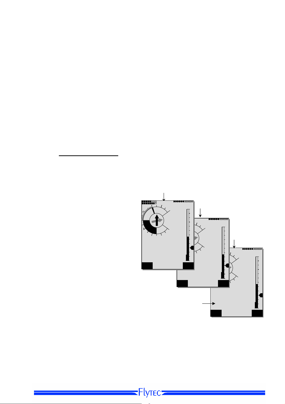
The scale of the analogue display is consistently 0,2 m/s
over both scale ranges ! The range of the first scale extends
from 0 up to +/- 4 m/s. (fig. 1) There after the scale display
switches automatically to the second scale range which
extends from 4… 8 m/s. The second scale is afterwards
displayed with a white bar on black base. (fig. 2)
The response characteristics of the analogue Vario and of
climb- or sink acoustics can be adapted within a wide range
in accordance to pilot’s needs or the weather
conditions. In order to simplify the settings, Flytec has
defined 5 basic- resp. turbulence filters.
Tip: By use of the PC Flychart Software Extras ->
Flightinstrument Options, all Vario characteristics can be set
easily and comfortably. With the tone simulation the
adjusted values can easily be checked simultaneously !
2.2.1.1 Basic filter
Main Setup Menu
.
Filter No. Filter
0 Very high turbulence filtering 1.8s
1 High filtering 1.4s
2 Default Normal filter 1.2s
3 Weak filtering 0.8s
4 Very weak filtering 0.6s
⇒
User Settings ⇒ Variometer ⇒ Basic filter.
m/s
1
m/s
5
2.2.2 Digital-Vario (Average Vario)
The Digital Vario has a scale of 10 cm/s and an extensive measuring range of up to +/- 100 m/s.
It is therefore also appropriate to display and record even measuring flights up to the free fall.
2.2.3 Variometer Acoustics and Volume level (Sound)
In order to enable the pilot to follow the current sink rate without looking on the instrument, the VarioAcoustics generate a tone sequence dependent on the value data. The Vario-Acoustic corresponds
always to the value of Analogue-Vario.
The sink acoustic of the variometer can be adjusted in the FLYTEC 6040 instrument to the
personal needs of the pilot.
P1
2
4
N
E
W
2
6
N
W
2
fig. 2 Vario 5.0 m/s
S
m
2067
QNH
4
3
fig. 1 Vario 1.5 m/s
P1
8
E
S
m
2481
QNH
4
3
km/
Int
1.
1013
km/
Int
5.0
1013
4
3
60
50
40
30
60
50
40
30

Operation Manual FLYTEC 6040 GPS 22
2.2.3.1 Audio Level
Short pressure on the Audio Level-key shall increase the
volume level each time by 25 %
In the main Setup menue the pilots sets the level on
which the sink tone and the sink alarm are activated:
Main Setup menue
acoustics
2.2.3.2 Variometer Acoustic Settings
The climb tone is a frequency modulated beep tone whose pitch and beep tone sequence increase
rhythmically at increasing climb rate. The pulse/pause ratio is 1:5.
The sink alarm is a continuous sound which is activated by passing the sink alarm level.
The sink alarm is being heard also the audio has been set off !
The following settings are possible in Main Setup Menu -> User Settings -> Variometer Acoustics:
Acoustic Settings
Sink toneF = Basic Ton pitch Variometer Sink
(Ton pitch when sink tone is being heard) .
Sink tone level: Sink tone level
Sink tone Alarm: Sink tone Allarm leel
Main Setup Menu
Variometer acoustics
All the sounds effects which are described in this passage can be checked out directly on the
Instrument by entering the simulation modus
Tip The PC software FLYCHART 4.52 enables a comfortable setting of all vario acoustic
parameters. (go to extras-Flight instrument options-Acoustics). The parameters which are set
can be cheked out by the tone simulation option.
⇒
sink tone and sink alarm level
By use of the key Audio Level is adjusted the volume level of internal
loudspeaker. Indeed for five values from soundless to maximum sound level. The
selected value is displayed on the Info-line and is confirmed with a short beep or
double-beep. The adjustable sound levels are:
0 - 25% - 50% - 75% - 100% - 0.
P1
3
2
m/s
N
⇒
user settings ⇒ Variometer
Climb
2
W
E
S
3
-2.
28
4
Ku
0 m/s
No tone
Range
Sink Tone
Range
Sink
⇒
User Settingt. ⇒
⇒
Sin ktoen level .
Sink Ton
Alarm
K
Q

Operation Manual FLYTEC 6040 GPS 23
2.3 Speed
Apart from Vario and Altitude the flight over ground is indeed one of the most decisive messages.
Thanks to the GPS, the speed over ground can be displayed accurately. The 6040 instrument has
two speed indication systems which operate independent from each other.
2.3.1 Wind vane sensor
The wind vane sensor is one of the speed system of the 6040. The 6040 has an entry for reading
out electronically the speed datas, which are measured by the vane sensors.
Advantage of this system: Wind vane sensors already start measuring wind from 1 km/h very
accurately. Theses sensors are very ideal to measure already small wind speeds at the start
Site. (wind vane sensor system optional)
The wind speed display can be adjusted for each sensor via a correction factor: The factory set
value is 100 %..
Main Setup Menu -> User settings -> Speed -> setting wind vane sensor
The wind vane sensor measures the true air speed.
2.3.2 GPS Speed
In case no wind vane sensor is used, the GPS speed over ground is indicated in the speed display.
Speed readings are analogue, as well as digital. The user
may select in
Main Setup Menu -> User Settings -> Speed ->
Speed Mode, if he prefers the reading as True or Indicated
Airspeed. Regardless of which sensor type is used, on
the COMPEO+ both speed readings are visible. In the same
Menu item the pilots of paragliders may set a lower display
range of 20 ...60 km/h on the analogue scale. (factory setting
is 30 ... 90 km/h)
Upon exceeding the analogue speed scale it shall not be
shifted, in this case the digital display upside the analogue
scale is only valid.
2.5
2816
Alt 2
1165
GLZGrund
8.6
Wind
12
56
Int
Km/h
38
Alt1
GPS
40
30
20
10
0
2.5
2816
Alt 2
1165
GLZGrund
8.6
Wind
12
56
int
Km/h
57
60
50
40
30
20
10
0
Alt1
GPS
2.4 Time of day and date
Notice: time of day and the date do not need to be adjusted. They are taken automatically from the
GPS-Receiver. However, any time zone difference from UTC (World Time) needs to be entered
with a positive value if the time zone is located East of Greenwich, or a with a negative value, if it is
at the West of it. Time zones with 0.5h UTC Offset are also adjustable.
This setting is entered with Main Setup Menu
Important: all internal calculations of the instrument are made in UTC (Coordinated Universal
Time). The local time is just used as „Time“ display and calculates simply the UTC plus or minus
the UTC Offset.
For the take-off time at Competition Routes the local time is binding.
⇒
Instr. Settings ⇒ Time zone.

Operation Manual FLYTEC 6040 GPS 24
2.5 Temperature
The FLYTEC 6030 GPS is provided with a temperature sensor for the temperature compensation
of pressure sensors, as well as for the automatic display contrast control. Temperature reading is
possible in degree Centigrade or Fahrenheit. Main Setup Menu
⇒
Instr. Settings ⇒ Units.
Notice: the temperature sensor measures the internal circuit board temperature, but in no way
the outside air temperature! The inside temperature of the casing may be higher or lower than the
ambient air temperature, especially when the instrument is exposed to direct sunlight.
2.6 Envelope Temperature
The envelope temperature is being transmitted by radio to the radio transmission unit TT34
The TT34 radio transmission unit is being switched on automatically by an active envelope
temperature, and is being switched off automatically if the envelope is not being used any more.
The temperature sensor transmits its data in a cycle of four seconds. During a balloon event where
you find many balloons close to each other the TT34 does not interferes with each other. In order
to avoid interferences, each TT34 has an individual identity number (ID), which is being transmitted
with the radio protocol. The 6040 instruments only accepts the radio dates, which are identical with
the ID-number registrated in the 6040 instrument.
For setting the ID-number go to the Main Setup Menu
Note: A received signal with an invalid ID-number is being indicated as „ID“in the display field
envelope temperature
Envelope Temperature Display: Temperature is being displayed as soon as the radio
transmission unit TT34 starts transmitting valid datas. In case no datas are being received a
broken line is being displayed in the display field. If there is no valid signal received for more than 2
min. an acoustic signal is also activated.
Tip: The quality of the signal is being displayed in
the main-display screen as well as in the windlayerdisplay screen..
2.6.1.1 Personal temperature alarm
If the given alarm level is reached the personal temperature alarm goes on. Then an impulse tone
Is activated. By pressing the OK key for 30 seconds the alarm can be switched off. The alarm re
sounds until the balloon is out of the alarm level bench again.
By pressing the Temp((.)) key for a long time, the
temperature alarm function is activated
By pressing an arrow key for a short time the alarm
level can be adjusted by one temperature unit steps.
While pressing this key continuously, the displayed value
is changing until the pressure on this key is released.
The temperature alarm can be set between 40 °C
(104° F) an the maximum envelope temp which is set by
the envelope manufacturer
.
⇒
Instr. Settings ⇒ TT34 device number.
P1
m/s
1
. . .
2
4
N
E
km/h
Int
5.0
. . .
Temp uv 95
49
60
50

Operation Manual FLYTEC 6040 GPS 25
2.6.1.2 Maximum Temperature Alarm
The maximum envelope temperature is a default value recommended by the manufacturer and can
not be manipulated. If the pilot reaches the maximum alarm level a temperature alarm will always
go on. The alarm sound will be heard as a constant tone until the maximum envelope temperature
is not reached any more.
The maximum envelope alarm can not be switched off
2.6.1.3 Temperature sensor failure
If the temperature sensor is not working properly any more, a symbol which indicates the
interruption --¦ ¦-- appear in the envelope temp display. Simultanously the temperature alarm goes
on.
2.6.1.4 TempRx Empfang On/Off
In case no temperature transmission unit is in
Use, the radio receive function for the TT34 can be
switched off, by pressing the TempRx key for a
short time. The switched-off status is indicated in
the temperature reception display by “Off”
2.7 Temperature transmitter FLYTEC TT34
The radio transmission unit TTT34 is operating with a 9-V battery. The temperature transmission is
switched on automatically as soon as the differential temperature between the instrument and the
envelope temperature (factory default value) is being recognized by the TT34 unit.
.
Switch on: Differential temperature of > 15ºC or abs. > 50ºC
Switch off: Differential temperature of < 15ºC and abs. < 50ºC
The operation time fort the Alcaline-battery lasts for
about 3 years and with a full operation time of around
200 hours.. The battery status is indicated in the
main display as well as in the windlayer
The TT34 unit is mounted on the outside of the envelop. The temperature sensor must be
laid to the inner side of the envelope and must be solidly mounted in a way that he touches
the envelope tissue.
The mounting must be carried out exactly according to the regulation. (See attachment
on page 55)
m/s
1
P1
2
4
N
E
km/h
Int
5.0
49
60
50

Operation Manual FLYTEC 6040 GPS 26
3 Navigation
Navigation activities without operating GPS-Receivers is unthinkable these days. Indeed
a chain of satellites is orbiting the Globe. It provides the possibility to determine worldwide
one’s own position very precisely, if minimum 4 satellites are received simultaneously.
The FLYTEC 6030 GPS calculates several readouts by position determination made by GPS.
3.1 Assesment of GPS Reception quality
The FLYTEC 6030 GPS is fitted with a 16-channel GPS-Receiver which is featured with lesser power
consumption and also a significantly shorter satellite detection time. Precision of position is between 7
to 40m. As an average one may assume approx. 20 m.
Normally the instrument recognizes its position under
unobstructed view conditions after
maximum 1 to 2 minutes. If the receiver is switched-off for
a short time (less than 2 hrs.),
the time for new position finding is less than 10 seconds
as a rule. Buildings, mountains or thick forest affect
reception quality of the receiver. Therefore, you should
always look for the best possible visibility around you and
the antenna in the casing should point upwards to the
sky.
In particular when mounted on the steering holder of the
hangglider, we recommend not to have the instrument
fixed under the pilot’s head on the middle of the basis, but
indeed sideways.
In this position the Compeo+ should not have more than
45° deviation from horizontal position
so that the antenna points upwards.
Because the receiving strength of the satellite signals is only approx. 1/1000 of mobile radios, these
radio sets and other disruptive factors (like notebooks) should be operated as far away as possible
from the FLYTEC 6040
The number of received satellites is shown on the upper right side of the bar scale. The longer the bar,
the more precise is the reception quality.
m/s
1
P1
2
4
N
E
As soon as the instrument has sufficient GPS reception after energising, the date and time of day is
recorded into the internal memory. This action is signalled by the instrument with a slight beep tone.
GPS
Antennenbereich
km/h
49
Int
5.0
60
50

Operation Manual FLYTEC 6040 GPS 27
3.2 Compass and flight direction
In contrast to a standard magnetic compass which is oriented to the
magnetic lines of force of the Globe, the GPS compass can show
direction only when the user moves about.
However, it has the advantage that it is not subject to any grid
deviation and does not show any deviation as a result of iron or any
magnetic material either. Its zero point always corresponds with true
geographic north (0 or 360 degrees).
The course, that is the flight direction (= Track), is calculated from a
series of positions. If the user remains stationary at the same
location, then the course (track) and compass needles are undefined.
The exact course, (this is the direction in which the user travels over
ground), is always at the top of the compass, but can also be read in
the display Track. When circling in a thermal the compass rose only
appears to turn; in reality the needle does not move; it’s the casing
along with the aircraft, which moves around the rose.
m/s
3.2.1 Track and Bearing
Track is the direction into which an aircraft is moving over ground. The geographic true
North direction is always 0 or 360 degrees. ( East = 90 ; South = 180 ; West = 270 degr. )
Bearing is the direction (according to the system described above) to a selected Waypoint seen from
the viewer
Caution: Track or Tracklog is also called the sequence of recorded positions during one flight.
WP 2
Kurs Linie
N
Course
Kursabweichung
Crosstrack error
Peilung
Bearing
Geschwindigkeit
Speed
Distanz
Distance
Kurs
Track
WP 1
MC
P1
N
W
3
4
E
S
3
m
4
2
2

Operation Manual FLYTEC 6040 GPS 28
3.3 Waypoints and Coordinates
A waypoint is any single point on the earth’s surface that you would like to go to.
The FLYTEC 6030 GPS can save up to 200 different waypoints. Each waypoint can have up to 17
characters, e.g.
“1123” meters (always above sea level). We now only need the position of Waypoint on the earth’s
i.e.
“Fiesch Airfield”. In determining the waypoint, it is also necessary to enter the altitude,
surface. For this purpose the COMPEO+ utilizes the geographical map system named WGS84 (World
Geodetic System 1984). This reference system assumes that latitude is measured from the equator (0
degrees) to the North Pole, 90 ° N, and to the South Pole - 90 ° S. Longitude is measured from the
Greenwich zero meridian (near London), East is counted positive and West is negative up to +/-180°.
However, the FLYTEC 6030 GPS also converts Waypoints entered according to the previous norm,
introduced by Bräuniger: 3 letters and 3 numbers. Example: FIE112 indicates a Waypoint with the
name FIExxx and an altitude of 1120 meters above sea level
In Basic Settings / Coordinate Format the data entry format is selectable between:
1) Degrees Minutes Deci mal places of Minutes (dd°mm.mmm) (Factory setting)
2) Degrees Minutes Seconds (dd°mm’ss“)
3) Degrees Decimal places of Degrees (dd.ddddd)
4) UTM (a grid system with a 1 km raster in both N-S and also in E-W direction)
5) Swiss Grid
Basically one should always try to use possibility no. 1 (=factory setting), because only this format is
using exactly the same calculation format as the GPS receivers do. With all the other formats rounding
errors could sum up to 20 m.
It is exclusively calculated with the WGS84 system. Different geodetic systems are no longer
selectable.
3.3.1 Alter, delete or insert waypoints
In this position of Set-Menu the waypoints may be managed. After briefly pressing the OK key
the display will show the list of saved WP. In case this list contains more than the visible 8 WP,
then a down arrow Ð at the right lower edge of the list warns that more pages are to follow.
To scroll down to the next page, press the ► key, now WP 9 … 16 are displayed etc.
Tip: Waypoints may also be set comfortably on the PC by use of the
„Flychart 4.52“ PC-Software and be transferred via the PC-interface
to the instrument.
Using the keys ▲ and ▼ it is possible to select an individual WP and
to alter it after pressing the OK key.
The 1st letter of the WP-name will blink, again with the ▲and ▼
keys the required letter is selected; there are numbers, letters,
as well as a set of special characters to choose from. By pressing
the ► key, you move forward to the next letter etc.
With the F1 key you may shift between capitals and small letters.
With the F2 key one single character is deleted (Rub out).
You can enter a maximum of 17 characters. Once the name has
been entered completely, confirm by pressing the OK key. Now
the WP altitude will blink and require any alteration. With the
keys ▲▼ the altitude value is entered and confirmed by pressing
the OK key. Now the position of WP is next. At first the latitude is
entered in degrees and confirmed with OK, afterwards the minutes
and then the decimals of the minutes. The same procedure is applied for the longitude.
Continuous keystroke changes the values to be set faster.
Waypoints
-----------------------------------------Flytecn
Calandal
Ocala
Stanserhorn
Niesen
Fantasy of Flight
Astatula
----------------------------------------- Used Waypoint 7/200
Astatula
Alti 245 ft
Lati N 47’ 55.116
Longi E 008’ 16.813
Ins.
Wayp.
Del.
Wayp.

Operation Manual FLYTEC 6040 GPS 29
6
Delete Waypoints
The selection of WP’s to be deleted is effected with the ▲ and ▼ keys.
Pressing the F2 key (Del WP) enables the delete function, for data safety the COMPEO+
is asking again: “Delete Waypoint?”. The reply “Yes” or “No” is at choice, but it is also possible
to discontinue the deleting procedure by use of the ESC key and return to one level before.
Insert Waypoints
Pressing the F1 key (Ins WP) enables this function. Entering Waypoint names, altitude and
position is operated following the same scheme as described above. After confirming all
entries with the OK key, the new WP is inserted to the list in alphabetical order.
In total 200 WP may be saved in the FLYTEC 6040 GPS.
Notice:
after entering new Waypoints, (for ex. for a new Route entry) these can be used only if
in between you have switched back to the normal flight mode with ESC.
In addition, the Route into which the new Waypoint was inserted must not be active.
Therefore, first change into route selection by prolonged pressing of the Route key and
with the help of the F2 key (Cancel Route) deactivate the Route.
The more Waypoints are saved in the memory, the more slowly the navigation becomes in
Main Setup Menu, as the list is rearranged again in the background over and over.
3.3.2 Display of actual coordinates
If the FLYTEC 6040 receives satellites by GPS-Receiver, the actual position is displayed by
briefly pressing the
screen will automatically reappear. This function is useful in relaying your location to some person
after landing, who will retrieve you from there. Also when entering a Waypoint
⇒
with WP
F1AddWp the coordinates are displayed.
i Info key in the instrument’s information field. After 20 sec. the previous display
3.3.3 Memorising the actual position
It may happen from time to time that the current position
should be saved as a Waypoint. For this purpose the WP
key should be pressed during 3 seconds and subsequently
⇒
F1AddWayp.
In response a beep will chime and the momentary
coordinates shall be saved in the memory as a Waypoint.
As the Waypoint name the FLYTEC 6030 GPS uses the
letter
M (for marker) and afterwards the actual date and the time
of day in UTC.
Example: M.22.04. 11:16:49 stands for 22nd April at 11
hrs. 16 min. 49 seconds (UTC). Naturally this WP name
may be altered later into a more meaningful name, for ex.
“Fiesch Airfield".
Add
Wayp
16
5
. . .

Operation Manual FLYTEC 6040 GPS 30
3.3.4 Go-To – Function
MC
Prolonged pressure on the Go To key switches the lower half of
the instrument into the Go-To-mode. This function allows for
searching a Waypoint stored in the memory of the Compeo+
and to select it for a flight to goal. At the same time the next Waypoints
are listed in the order of shortest distance to the user.
The figure behind the WP-name indicates the distance in km.
If a WP was selected with the ▼ arrow key, it can be confirmed
by pressing the OK key. The Go to-function may be deactivated
by pressing the F2 key (Can Go to ).
.
3.3.5 Distance to Waypoint (User Datafield)
2
N
W
2
- - - - - - - - - - - - - - - - - - -
Select Waypoint
Flytec AG 036
Calanda 160
Crassons Grat 267
Fiesch Landepl 112
- - - - - - - - - - - - - - - - - - - -
. . .
P1
3
4
E
m
S
4
3
Km/h
Int
0.0
816
Alt 2
0
57
90
80
70
60
50
30
Cancl
Goto
Only in case a Waypoint has been selected manually with the “GoTo”
function, or automatically with the "Route" function, the horizontal
distance seen from the viewer to the waypoint is displayed here. The
scale is 10 m (for distances below 10 km) otherwise it is 0,1 km.
Also when the Waypoint is used as turning point in a competition, it is
always the distance to the centre of the cylinder which is displayed.
3.4 Routes
A route is an arrangement of various Waypoints over which one would like to reach a goal.
Of course, the Waypoints used on a Route have to be saved in the unit’s memory. Similarly to
the Go-to-function the pilot should fly from WP to WP in a travel optimized mode, which means
that with help of the McCready-theory he will be able to complete his task within the shortest possible time.
While inside the Go-to-Function the next Waypoint needs to be selected from a list each time by prolonged
pressing of the Go-to key, when flying Routes it is possible to switch forward by briefly pressing the key ▲
(next WP) or ▼ (previous WP ).
Altogether, the FLYTEC 6040-GPS can have up to 20 Routes created. Each Route may contain max.
30 WP’s. The one and same Waypoint can be used more than once along a Route, and the same
Waypoint may be included on other Routes as well.
Notice: in a normal Route, when reaching a waypoint, there is no automatic shift to the next WP!
For the automatic forward shift it is required to use the Competition-Route function!
Important: Once a WP has been used along a Route, it can no longer be deleted from the WP list..
240 153

Operation Manual FLYTEC 6040 GPS 31
3.4.1 Creating a Route
With Main Setup Menu ⇒ Routes access is given to the list of stored
Routes. (max. 20 Routes). Within this list one can select by use of the
arrow keys ▼ or ▲ one of the Routes, or by pressing the F1 key (Ins.
Route) a new Route can be created.
After pressing the F1 key (Ins. Route) at first a name has to be entered
for the new Route. The cursor will blink on the
1st letter of the word " Xxxxx ". With arrow keys ▲ or ▼ it is altered up
to the desired letter. By use of the ► arrow key one proceeds to the
2nd letter, alters it, and so forth. By pressing the OK key
the data entry of the Route’s name is completed. At this point the
individual Waypoints need to be inserted into the Route. After
pressing the F1 key (Ins.Wayp.) the list of available Waypoints
will
appear in the bottom half of the readout screen in alphabetical
order. At the same time one shall see the request: "Select
Waypoint No 1". Again by using the ▲ or ▼ arrow keys the 1st Waypoint is
selected and is added to the Route by pressing the OK key. This
is indicated in the upper half of the screen. By pressing the F1 key
(Ins.WP.) one can select the 2
nd
WP and add it to the Route by
pressing the OK key again, and so on. The highlighted Waypoint
(offset in black) of a Route is always the last one entered, which means
that the function “Ins.WP” will set the next WP to be entered after the
one being highlighted in black. If, for instance, you want to insert an
additional waypoint after WP No. 1, then WP 1 has to be highlighted,
followed by pressing the F1 key (lns.WP); then the request “Select Waypoint
No 2” shall appear. If you notice, for example, that Waypoint No. 4 must be
changed, then you select and delete this WP and insert a new one after the
existing WP3 by pressing F1. Again the list of available Waypoints appears
along with the request “Edit Waypoint No 4”. After selecting and pressing OK,
the old Waypoint is replaced by the newly chosen one.
If one wants to delete a Waypoint from the Route, it is marked and deleted by
pressing the F2 key (Del.Wayp.). The Waypoint is then deleted from the list
without any further prompt.
.
3.4.2 Altering a Route
You select a route to be altered with the ▲ or ▼ arrow keys and confirm with
OK. The Route’s name is changed first. If this is not required, then it is
sufficient to press OK again in order to get access to the Waypoints. As
described in the last paragraph, additional Waypoints can now be added or
deleted.
.
3.4.3 Deleting a Route
By using the ▲ or ▼ arrow keys one selects the route to be deleted
and confirms by pressing the key F2 (Del.Route). For data safety the
FLYTEC 6030 GPS inquires once again: “Delete Route?” which should be answered with “Yes” or “No”.
Notice: Routes may also be set comfortably on the PC by use of the „Flychart 4.52“
PC-Software and be transferred via the PC-interface to the instrument.
Route
- - - - - - - - - - - - - - - - - - - - COMPETITION-ROUTE
Stanserhorn-Planp
Fiesch- Oberalap
Cassons- Piz Guil
- - - - - - - - - - - - - - - - - - - - Route 2
Stanserhorn-Planp
Total Dist: 96
Waypoints: 8
- - - - - - - - - - - - - - - - - - - - -
Ins.
Route
Test-Route
- - - - - - - - - - - - - - - - - - - - -
Wegepunkt Test1
Wegepunk Testt2
- - - - - - - - - - - - - - - - - - - - -
Select Waypoint No 3
Wegepunkt Test3
Wegepunkt Test4
Wegepunkt Test5
Wegepunkt Test6
Wegepunkt Test7
- - - - - - - - - - - - - - - - - - - - -
Ins.
Wayp
Test-Route
- - - - - - - - - - - - - - - - - - - - -
Wegepunkt Test1
Wegepunkt Test2
- - - - - - - - - - - - - - - - - - - - -
Waypoint 1/2 in Route
Wegepunkt Test2
Total Distance: 49
- - - - - - - - - - - - - - - - - - - - -
Ins.
Wayp
Del.
Roure
Del.
Wayp.
Del.
Wayp.

Operation Manual FLYTEC 6040 GPS 32
3.4.4 Flying Routes
The Menu Routes is enabled by long pressure on the
Route key.
After this selection the list of Routes stored in the instrument
appears in the lower part of the screen.
Within this list one of the Routes can be selected by
use of the ▼ or ▲ arrow keys and can be activated by
pressing the OK key.
For an activated Route a thick black arrow positioned
in the centre of the compass rose points to the direction
of the next Waypoint. The direction to the next but one
Waypoint is illustrated in shaded mode.
Notice: an activated Route is kept enabled even after
switch-off and switch-on of the instrument! The Route
- - - - - - - - - - - - - - - - - - -
Select Route
COMPETITION-ROUTE
Route Demo2
Route Flytec
- - - - - - - - - - - - - - - - - - - -
. . .
may only be deactivated by the “Cancel Route” function !
If following switch-on of the instrument a black direction
pointer is visible in the compass rose, it indicates an
activated Route or a “Go To” function still in activity!
3.4.4.1 Distance to Start Site
The instrument memorises the coordinates from where the balloon flight starts (Flightaceptance)
The flight starts being counted if a GND Speed of 10 km/h for more than 60 seconds had been
reached. With the “distance to start“ the distance to this point (which is normally the start site)
can be displayed.
MC
2
N
W
2
4
E
S
4
3
P1
3
0.0
m
816
0
Int
Alt 2
Km/h
57
90
80
70
60
50
30
Cancl
Route

Operation Manual FLYTEC 6040 GPS 33
È
3.4.4.2 XT Error, Crosstrack Error
This field indicates the shortest distance (perpendicular to the Track in relation to a map view)
to the active leg of a Route.
Waypoint
Negative
value
Start
Pos 3
P3
È
10
Positive
value
Buho
È
The accuracy of the displayed value depends on the length of the active leg. The largest inaccuracy
arises in the centre between start and the next Waypoint if one is very close to the track (the
angles become very flat). With 50 km distance between start and Waypoint, the inaccuracy in the
centre can reach up to 400 m.
Positive values are displayed if one is on the right side of the track, negative values when being on the
left of the track. Even when one has flown over the next Waypoint, the distance to the straight line is
displayed (see pos. 3)
3.4.5 Flight duration
The take off time is automatically recorded. The flight start time is perceived as soon as the
instrument has diagnosed a difference in height of about 30m upwards or downwards, or if the
speed over ground has been measured with more than 10 km/h since min. 60s.
For this purpose the GPS needs to be activated. In case the GPS-Receiver has no or only
poor reception quality, only the difference in height of about 30m is valid as criteria for flight recording.
Moreover, only flights which are lasting more than 3 minutes, are log recorded.
The flight time can be displayed in the user selectable fields. The unit will also recognize
autonomously the end of the flight. It is the basic condition for the end of the flight that neither
speed over ground has been measured with more than 10 km/h during min. 60s, nor that the
Vario pointed to more than 0.1 m/s. In Basic-Settings one can select instead of automatic flight recording
the manual procedure.

Operation Manual FLYTEC 6040 GPS 34
4 Map of Flight Obstacles (Restricted areas)
It is possible to enter on the FLYTEC 6040 GPS up to 300 flight
obstacles such as CTR’s, TMA’s, air fields, danger areas, cables or
also a wildlife protective area, of which the graphs are displayed on the
map page. These restricted area zones may comprise straight lines,
but also arc segments or just circles. These sectors are displayed in
+
Buho
map mode. Each CTR may be composed of max. 110 Waypoints. As
soon as the distance to CTR falls short of a warning limit to be set in
Setup Mode (factory setting = 200m), this distance is displayed
additionally on the graphic map screen, as well as on the standard flight
display in the Info line. CTR 0.20 Km The distance to the next CTR
10
can also be displayed as user defined data field.
If the pilot is inside of the CTR, then Dist.to CTR is always indicated as
being 0.
For each CTR is assigned a name and a comment to be freely edited
by the pilot. The names of the five next Air space CTR’s may be shown
with the
i key in Map Mode. The relevant comment may be used to
inform the pilot during flight about the upper or lower border limits of
the CTR. The sequence of these CTR’s corresponds to the distance
from the momentary position. A second pressing on the
i key removes
this information, or the Info page disappears after 30 seconds.
The map section can be altered as follows:
F2: Zoom in: the map scale is gradually increased up to approx. 0,5 km.
Thus even details are clearly recognisable.
F1: Zoom out: the map scale is gradually decreased, down to the
screen-optimised illustration. Maximum is 50 km.
4.1 Flight obstacles – Edit manually
CTR's can be entered into the instrument either manually under Main Setup Menu
or more easily by use of a PC program, e.g. Flychart which is available for download via Internet
on our homepage (
www.Bräuniger.ch). The procedure for manually setting, altering and deleting CTRs
is operated according to the same system which is used for setting, altering and deleting Waypoints
and Routes.
it is possible to use up to 300 CTR’s, depending
on how complex these are. You can under
Main Setup Menu -> Manage Memory -> Delete
All Air Space store the CTR Innsbruck into the
instrument and subsequently alter it under Main
Setup Menu -> Air Space.
Restricted areas
-------------------------------------
Innsbruckck
-------------------------------- Ctr 1
CTR Innsbruck
Bemerkungen!
Warning Dist.[m]: 50
No of Elements: 7
------------------------------------
Ins
CTR
Del
CTR
⇒
Air Space
Comments
Warning Dist.
Number
Elements / Points

Operation Manual FLYTEC 6040 GPS 35
The CTR is defined by key points and arc segments or just by a circle. When entering these
key points it must be taken care of that the key points are precisely created in their order of
appearance (to the right or to the left) in which these lines should be displayed later.
The FLYTEC 6040 GPS draws automatically a line from the recent Waypoint to the first one.
It is therefore not necessary to repeat as last waypoint the first one.
As type the following elements can be selected:
Point: key point
Center: centre of arc segment
Startboarder: start point of arc segment
Stopboarder: end point of arc segment
Circle: centre of the circle plus Radius
Example
counter-clockwise
7. Point
6. Point
2. Point
1. Point
To enter arc segments, the following sequence must be observed:
Long, Lat centre;
Long, Lat start point of arc segment;
Long, Lat end point of arc segment;
Rotational direction (+clockwise, - counter-clockwise
For circles the centre and the Radius are sufficient.
Long, Lat of centre;
Radius in km
5 Stopboarder
Dir -
3 Center
4 Startboarder
Dir -
1. Point
2. Point
6. Point
Innsbruck
- - - - - - - - - - - - - - - - - - - -
Point 1/7
Point 2/7
Center 3/7
Startb 4/7
Stopb 5/7
Point 6/7
Point 7/7
- - - - - - - - - - - - - - - - - - - -
Point
Dir
Lati: N 47’19.500
Longi: E011’04.500
- - - - - - - - - - - - --------

Operation Manual FLYTEC 6040 GPS 36
4.2 Map of flight obstacles - Edit with Flychart
The Air Space map can be entered into the instrument comfortably on the PC by use of the freebie
software program Flychart via PC-interface.
4.2.1 Air Space in OpenAir Format *.txt or *.fas
Flychart is appropriate to download Air Spaces in the so called OpenAir Format. On the Internet the Air
Spaces are normally made available as *.txt file, e.g. on
For Switzerland Air Spaces can be downloaded under
*.fas. For Germany and Austria the website
is recommended.
Tip: create within the Flychart folder a new folder with the name Air Maps or Airspaces in order to
facilitate recovery and management of the Air Space files which had been downloaded.
Flytec/Bräuniger Air Spaces ending with *.txt or*.fas can be edited with any text editor, or very comfortably
with the Flychart Air Space editor. Start point and end point do not need to be identical. Start point and
end point do not need to be identical.
Example for such a Restricted Area:
*## (CLASS D) INNSBRUCK CTLZ ###
AC D
SB 0,255,0,120
AN OVV: 120.1
AL SFC
AH 11000 MSL
DP 47:25:00 N 011:44:20 E
DP 47:18:20 N 011:48:10 E
DP 47:07:55 N 011:10:05 E
DP 47:10:40 N 011:00:45 E
DP 47:19:30 N 011:04:30 E
DP 47:16:55 N 011:13:30 E
http://www.dfc-saar.de/ -> GPS Lufträume
4.2.2 Calling the function Air Space in Flychart
Click on the Icon „configure flight instrument“.
In instrument flight options select Air Space. An empty Air Space window shall appear
http://soaring.gahsys.com/SUA/
http://www.flyland.ch directly in Flychart Format
.

Operation Manual FLYTEC 6040 GPS 37
4.2.2.1 Downloading Air Spaces
Air Spaces can now be downloaded with the button Load (Laden).
4.2.2.2 User Air Spaces ending with *.fa5
These are Air Spaces which have been readout by the user out of a list and subsequently saved with
the button “Store” (memorise). These Air Spaces are not subject to be edited.
4.2.2.3 Selection of Air Spaces
The standard version of FLYTEC basic list allows selection of up to 20 Restricted Areas for
transmission to the instrument, storage and for being called up again. The upgraded version allows
selection of up to 300 Restricted Areas for transmission to the instrument, storage and for being
downloaded to the instrument. The Restricted Areas which are stored in the instrument shall
be overwritten upon transmitting.
The active selection which is stored or transmitted to the instrument, is marked with a green check.
Non active Air Spaces are marked with a red cross. For change of selection one can call up a
dropdown menu by using the right side mouse button and carry out the following action
with Select-> Reverse (select -> Inverse) the current selection can be altered. A red cross becomes a
green check and converse.
with Select -> All (select> all) all Air Spaces of the list are selected and are marked with
a green check.
with Select-> None (select -> none) all Air Spaces of the list are dropped and are marked with
a red cross.
By clicking with the left side mouse button on an Air Space this item is selected and will then be marked
in blue.
With Ctrl click several Air Spaces are selected.
With Shift click one zone of Air Spaces is selected.

Operation Manual FLYTEC 6040 GPS 38
p
p
After having called up this function it is at first required to click into the list in order to activate
all Air Spaces contained in the list. The graph is displayed in the right side part of the screen.
The activated Air Space is each time marked in red.
From Flychart Version 4.52.31 on it is possible to display Air Spaces also graphically by using the
mouse in Map mode, which may then be selected or dropped with the right side mouse button.
4.2.2.4 Editing Air Spaces
In the same dropdown menu some more activities may be
executed:
with „alter“ („alter...“) it is possible to alter the name, comment
or also the coordinates.
With „new“ (new...“) it is possible to enter new Air Spaces manually.
This is convenient for specific Air Spaces such as wildlife protective
areas or exceptions in official Air Spaces made on bilateral agreement.
With „delete“ („delete“) Air Spaces are erased from the list.
With double-click of the left side mouse button access is given to
the detail view screen.
The name can be altered user defined with the right side mouse button ->alter ( -> alter).
One and the same name is only admitted once in the list and may contain up to maximum
17 characters. We recommend to apply a clearly comprehensible abbreviation. As a standard
are used for data files of the DAFIF data base the official 3-digit aviation name of the airfield,
as well as an abbreviation of the type and of the radio channel. However this results in double
names in the list, because the description may be longer than 17 characters and is then
barely comprehensible.
The description can be altered user defined with the right side mouse button ->alter ( -> alter).
This description is displayed on the instrument and may also contain up to maximum 17 characters.
We recommend to apply a clearly comprehensible abbreviation of the Air Space, as well as
complementary information, such as upper or lower height limits or the radio channel data of
the control tower. As a standard the altitude is indicated in meter or as Flight Level in the
DAFIF data files.
The warning distance is the vertical distance to the Air Space from which on a warning is
emitted in the lower info line of the instrument. The warning displays an abbreviation of the name
and the remaining distance. The coordinates of key points need to be entered in the sequence of key points
of the polygon.
The rotational direction can be clockwise or counter-clockwise
Coordinates of key points
Example
counter-clockwise
5
1
p 4
p 2
3 Center
a 3
Dir -

Operation Manual FLYTEC 6040 GPS 39
Arc segments or Radii
Radii are indicated in the following format:
Long, Lat centre; Long, Lat start point of Radius; Long, Lat end point of Radius;
rotational direction (+clockwise, - counter-clockwise).
Circles
Circles are indicated in the following format:
Long, Lat centre; Radius in km.
We recommend the following procedure:
• Select with the button „Download“ ( "Laden") a FLYTEC Air Space file (*.fas, *.fa5 or *txt). You
will now receive a long list and a complex graph.
• Click into the list, all Air Spaces appear in blue. Now select with Ctrl + left side mouse
button the single Air Spaces, for zones use Shift + left side mouse button. Select the
Air Spaces being important for you. They shall be displayed on the right side of the screen.
Please consider that in Map mode of the instrument it takes the more time for the screen
layout, the more Air Spaces are in the active zone.
• Now alter for the individual Air Spaces the name and description in abbreviations which
are comprehensible to you.
• Simplify complex Air Spaces of which only some parts are interesting to you by deleting
key points.
• Combine Air Spaces which are nested into each other and for which you are not
permitted to penetrate.
• Now you can store this file for later use with “save” ("save").
• With „send“ ("Senden ") the selected Air Spaces are transmitted to the instrument.
If acoustic is energised, a high pitch beep is audible for each Air Space which was
transmitted successfully. In case of unsuccessful transmittance the tone is somewhat
deeper, e.g. in case of double names. With “received” ("received") one can check
which Air Spaces are currently stored in the instrument.
Tip: create at first a user Air Space file containing the Air Spaces in your flight area.
This file may contain numerous Air Spaces. Open this file prior to the flight and download
only the Air Spaces to your instrument which you are likely to approach during this day.

Operation Manual FLYTEC 6040 GPS 40
5 Flight-Memory and Flight-Analysis
5.1.1 Flight logbook and Flight-Analysis page
The recording mode does not need to be specifically
activated, as each flight is automatically saved.
The flight memory used on the FLYTEC 6040 GPS not only
records flight altitude and flight speed (TAS), but it also
logs the position of the pilot and the GPS-altitude
⇒
in the WGS84-coordinate system. In Main Setup Menu
⇒
User Settings
recording intervals can be set. The selected value determines
the time interval in seconds, according to
which a new data set is entered into the memory
of the FLYTEC 6030 GPS. Minimum value is 2 seconds,
which corresponds to a recording time of approx. 9 hours.
At the maximum value of 60s interval the recording time will
add up to approx. 291 hours.
For tests or acrobatic flights a sampling rate of 2 seconds is
recommended. Another recommendation is the
Recording Interval between 5 and 10 s. Hereby also
narrow curves are well recognisable and the number
of data points for the external calculation of the OLC
points is kept conveniently clear.
Factory setting here is 10 seconds.
Flight memory ⇒Record. Intervals the
For the beginning of a flight the following agreement
is applicable:
start is recognised as soon as Groundspeed reaches
more than 10 km/h during min. 60s, or if altitude
difference of more than 30m was detected within 60s.
In each case, however, the previous flight history over
30 recording points is logged into the memory of the
FLYTEC 6030 GPS. Even the last 3 minutes prior to the
start of the logged flight are recognisable, as they are
recorded in 10 sec. recording interval.
The end of the flight is recognised in automatic
recording mode, if there is no speed for min. 60 sec.
(less than 10km/h GPS-speed or air speed)
and if no change in altitude occurs.
Then the standard display screen is automatically
switched to Flight-Analysis mode. From this moment on
the „digital signature“ of the flight is calculated and
shown by a notice in the Info-line. Please wait until this
calculation is completed. By briefly pressing the ESC key
one returns to standard mode.
It is also possible to switch the instrument to manual recording. For this purpose one has to select under
⇒
Main Setup Menu
By use of this setting the recording starts approx. 2 minutes after switch-on and is only
finished after the key ESC has been pressed for 3 seconds.
Begin of the recording is visible by the running „Flight time“- counter.
User Settings ⇒Flight memory ⇒Recording Auto/Man the item “No“.
Main Setup Menu
------------------
FFlluuggssppeeiicchheerr
WWeeggppuunnkktte
e
Routen
Luftraeme
>Benutzer Einstellungen
>Speicher verwalten
Simulation
Flight Memory
- - - - - - - - - - - - - - - - - - -
01.03.02 0:43:12
13.02.02 1:37:34
28.01.02 0:24:05
23.01.02 1:02:24
12.01.02 2:11:45
15.12.01 0:34:55
24.11.01 1:07:32
- - - - - - - - - - - - - - - - - - - - - - - - -
FLIGHT ANALYSIS
- - - - - - - - - - - - - - - - - - - - - - - - -
Date: 17.20.07 UTC
Start: 17:02:02 UTC
Stop: 19:55:32 UTC
Flight time: 2:53:30
Scanrate: 10 s
Max A1: 2823 m
Max A2: 1154 m
A3: 4273 m
Max Env. Temp: 86.2 C
Max Vario (10s): 2.2 m/s
Min Vario (10s): - 1.4 m/s
Max speed: 73 km/h
Show
Map
Recal
Sign.

Operation Manual FLYTEC 6040 GPS 41
r
Caution: make sure before take-off that the GPS-Receiver indicates to receive at least
4 Satellites in order to achieve valid recordings.
Comment 1: in the Flight Analysis are displayed max. values which occured during the flight.
Due to the fact that the display screen is updated every second, these 1-second values are saved
for the flight analysis. If one undertakes a download of such a flight afterwards on the PC using
a program such as Flychart, SeeYou, CompeGPS, MaxPunkte etc., these programs are only
appropriate to evaluate the flight records in IGC format. In the IGC file are saved the time (UTC),
position, barometric altitude, GPS-altitude and True Air Speed of the wind vane or pitot pressure
sensor. The programs now calculate the Variometer values from the altitude data. If for instance, one
has set a recording interval of 10s, and has covered a height difference of 5m during these
10 seconds, there will be calculated a Vario value of 0.5 m/s. However, during this time a 1-second
Vario value of 2m/s may have been performed. It is only this value which shall be indicated on the
Flight-Analysis page and it is not subject to electronic readout. On the flight analysis page both
values are displayed.
Comment 2: although the instrument is capable to store up to 100 flights, we recommend to save the
flights in regular intervals from the instrument to a PC and to reformat the flight memory afterwards
⇒
under Main Setup Menu
Memory⇒Delete all Flights. This procedure ensures the safe data storage
of your precious flights and that the instrument may perform new recordings again with a „refreshed“
flight memory.
5.1.2 Graphic display of Flights in Map format
The flight route of saved flights can also be shown on the Display screen for appraisal. Within
the item Flight Analysis the F1 key is taken for the function Show Map. After pressing this key
the screen-optimised illustration of the flight route is shown (North is at the top!).
In addition, stored Waypoints are presented with a cross and the name, as well as the map
scale as a short line with km indication. Now the illustration can be altered as follows:
F2: Zoom in: the map scale is gradually increased
up to approx. 0,4 km. Thus individual circles are clearly
recognisable (dependent on the recording interval which was
set).
F1: Zoom out: the map scale is gradually decreased,
up to the screen-optimised illustration. Maximum is 47.4km
Arrow keys Pan:
by use of these keys the
illustrated area can be shifted up, down, left or right.
OK: from each graph back again to the screen-
optimised illustration.
ESC: Return to the Main Setup Menu
All the other keys cause the Track in the current selection to
Quest
be redrawn.
Remark: as the screen layout will take a few seconds
to appear in accordance to the data volume, the message
Start: 17.11.07 14:31
Flight time: 3:14.45
Zoom
Out
Wait and Ready appears on the status line as user information.
If a zoom or pan key is activated during the screen layout, the
momentary process will be stopped and will resume with the new values.
Thus it is possible to obtain the desired graph rapidly.
Leesburg
Ready
G
iffin
Grant
Zoom
In

Operation Manual FLYTEC 6040 GPS 42
6 Data transfer
All data entered by the pilot, including Waypoints, Routes, pilot’s name, etc. as well as the
automatically recorded track log points of the flights undertaken by him are in the memory of the
FLYTEC 6040 GPS. Each of these track log point contains the time of day, position, GPS altitude,
barometric altitude as well as the flight speed. In this way, it is possible to graph the Barogram,
variogram, speed gram and course of the flight on a map for later evaluation. In Flychart 4.52
it is even possible to show the flight on the PC monitor in 3D on the corresponding landscape.
For this purpose the program Google Earth needs to be installed, along with an active internet
connection
6.1 Data exchange via PC
The basic equipment of the FLYTEC 6030 GPS includes a data cable for a USB PC interface USB Mini
B.
Due to this feature the data transfer can be carried out in both directions. The data transmission
is effected via serial interface COMX with: 57.600 baud; 8 data bit; 1 stop bit; no parity; Xon/Xoff.
The FLYTEC 6030 GPS can also be operated for data readout and entry via USB interface:
• entire instrument configuration (Basic Settings, user defined fields)
• list of Waypoints
• list of Routes
Only readout of flights saved in the flight memory is possible.
Important: for transmission of a.m. data the connection cable to the PC may only be
plugged into the FLYTEC 6040 GPS, after the instrument has been switched-on and the
program required for the data transfer was called up.
Important: at first the USB driver from Prolific included in the scope of supply needs to be
installed from the CD. For the installation of Flychart the installation of USB driver is effected
automatically
To perform data transfer the instrument needs to be switched to the Main Setup Menu by prolonged
pressing on the Menu key.
Please observe the instructions of the software being used for transfer of stored flight data.
(for most of the software programs it is required to switch to Flight Memory resp. to Flight
Analysis mode). There are various software programs available for creation of IGC-files, partly even for
OLC-files. More detailed information under
We recommend the use of Flychart which you may download from the Website
.
With Flychart it is possible to perform all instrument settings comfortably on the PC
http://www.onlinecontest.de/holc/ .
www.flytec.ch

Operation Manual FLYTEC 6040 GPS 43
g
6.1.1. Flight instrument Options
All settings can be performed or altered comfortably with Flychart 4.52
Benutzereinstellungen
und Instrument
Einstellun
en
6.1.1 Waypoints and Routes
In the same menu the way points and the routes can also be transfered from the Flychart
to the instrument. Flychart can also import and transfer data files of waypoints from See You or
Compe GPS or Garmin
6.1.2 Air Spaces
The very same is valid fort he Air Spaces. (see under Airspaces)
7 Simulation
After choosing the Simulation mode in the Setup menu and pressing the OK key, you reach
this highly interesting function. With the arrow keys and OK you turn the Simulation mode to:
“Yes” and confirm again with OK. Now the simulation starts and the last known GPS position is
applied.
With the ► and ◄ arrow keys you can adjust the air and ground speed; the ▲and ▼ arrow keys
change the sink or climb. If the stall alarm sounds, please increase the airspeed by a few km/h.
The F1 key is used for switching to various functions.
Next Func. Var ▲▼ Spd ►◄XX to alter Climb/Sink Air + GND-Speed
Next Func. Wind ▲▼ Trk ►◄ to alter an assumed Wind strength during climb and
to alter the Track (Flight direction) during sink phase
Next Func. Mod A1 ▲▼ Modify altitude Alt1
Next Func. Mod A2 ▲▼ Modify altitude Alt2
Next Func. S.Thr –▲▼ altering activation point of sink acoustic
Next Func. Change page ►

Operation Manual FLYTEC 6040 GPS 44
Likewise, the Go-To function can be called up to select a Waypoint. The distance to this Waypoint
appears. If the direction arrow in the compass centre points upwards, the pilot is moving towards his
goal and the distance to WP becomes smaller while at the same time the altitude is naturally
decreasing. If you now initiate a climb with the ▲ key, the FLYTEC 6040 GPS simulates circling up in a
thermal; the compass rose turns and the distance to goal continuously changes between somewhat
closer and somewhat farther away. Under simulation mode you can also test the different acoustics of
climb tone when altering frequency, pitch and modulation. Please shift
back to sink flight mode. After pressing the
to alter the Speed over Ground, i.e. simulate the wind influence. When using the ◄ and ► keys
it is also possible to change the flight direction, e.g. to fly directly to a WP.
One can also retrace perfectly in simulation a called-up Route. If you select this Route as CompetitionRoute, you will hear the characteristic tone upon approaching within 400 meters
of the Waypoint, which tells you that you are inside the cylinder. Moreover you can see the automatic
switchover to the next WP too. (Caution: for automatic switch-over the count down
timer must show positive values). By pressing the ESC key you can switch to map display and observe
the approach to the Waypoint cylinder.
If one has selected the function
Wind Track with the F1 key, it is real fine to simulate the influence of
head or tail wind during approach to the goal. It is indeed informative to see the influence of head wind
when approaching the goal.
It is really instructive to see how far the head wind will influence the readout of
During simulation mode the GPS-Receiver is switched-off and instead of its bar graph appears
the word "Simulation".
A simulated flight is well stored into the memory of the FLYTEC 6040 GPS, but however for such flight
the “Digital Signature” is not valid.
F1
key it is now possible by use of the ▲and ▼ keys
Alt a BG.
8 Battery- Management
The FLYTEC 6030 GPS provides 2 banks of 2 accumulators each. On the Main Display screen
there are two scales to indicate the approximate charge level of the accumulators. Upon switch-on
and switch-off the respective capacity of each one is displayed in percent for information.
In case of need, e.g. if the accumulators may not be charged in time, the FLYTEC 6030 GPS will also work
with standard Alkaline batteries. In this respect it should be considered that Bank 1 must always
be loaded. Bank 2 is the spare Bank and may be kept unloaded if unavoidable. However, it is
highly recommended to have Bank 2 also equipped. As soon as Bank 1 batteries are discharged,
the instrument automatically switches to this second spare bank. We recommend to interchange
the accumulators of Bank 1 after one year with those of Bank 2. In doing so it is ensured that the accumulators
are equally aged.
The FLYTEC 6030 GPS may be charged by use of the plug-in charger as standard accessory for alternating
current power supply ( 110 - 230 V~ ), or by using a vehicle battery (10 … 18V). The charging process of both
banks is optimised individually in accordance to the respective charge state by means of built-in charging
circuits! One charging cycle for empty accumulators will last approx. 4 to 6 hours. The two intelligent charging
circuits monitor the charging process and cut-off the charging as soon as the accumulators are fully charged.
During charging the two red LED’s are illuminated. In case of overheating or incomplete charging the
respective LED will be flashing! Accumulators should only be charged within the temperature range of +15 °C
up to +27 °C!
It may happen that in warm ambient temperatures the charging process will be untimely discontinued because
the batteries are heated. In this case the charging should be repeated a second time,
or charging should be performed over night.
Important:
the battery charge-state display is only operative if the charging process was correctly completed!
In case of untimely interruption this will result in a faulty charge-state indication! Moreover the chargestate display is inaccurate immediately after charging. The batteries are presented as
being fully charged, although this may not yet be the actual charge-state. The ambient temperature has
also its influence on the open-circuit voltage of accumulators. The best security for correctly and fully
charged batteries is provided when the instrument is charged over night.

Operation Manual FLYTEC 6040 GPS 45
The following batteries are appropriate for use:
2 pieces each per Bank NiMH Accumulators 2100mAh or more, 1.2V size AA. Estimated operation time
2 times 15h = 30h in total (delivery status).
In case of need, e.g. if the accumulators may not be charged in time, the FLYTEC 6040 GPS will also
work with standard Alkaline batteries!
2 pieces each per Bank Alkaline High Power Batteries 1.5V size AA. Estimated operation time 2 times 20h = 40h in total.
The relevant battery types are to be set under Main Setup Menu
A wrongly entered setting may lead to the result of the instrument’s premature and complete
switch-off when shifting from Bank 1 to Bank 2 and thus provides incorrect status information!
We recommend not to use NiCd Accumulators. These batteries have significantly reduced capacity and
they are less environment-friendly. Also the switching threshold is not laid-out for NiCd Accumulators.
Remark: the estimated operation time as mentioned before is based on normal temperatures
of approx. 20 – 25 °C. At low temperatures the batteries and accumulators have a markedly
shorter service life.
Bank 1
Bank 2
Lade LED
⇒
Instr.Settings ⇒Batterytype.
9 Transferring new software-(-firmware)to the Flytec 6040-GPS
As is the case with many other present-day instruments, there is also the possibility to up-date
the software (firmware) version. Hereby even future requirements presented by pilots or new
Competition regulations may be rapidly implemented. The manufacturer Bräuniger GmbH
shall post from time to time program up-dates of the FLYTEC 6030 GPS firmware on its Internet
homepage, which can be downloaded by the user free of charge for storage and subsequent
transfer to the FLYTEC 6040 GPS.
In order to be able to write into the COMPEO+ flash memory with a PC, the program „Flasher.exe“
is required, which is available in zipped format file under the name of “Flasher.zip”. Moreover
also the intrinsic firmware to be uploaded needs to be obtained from the homepage.
Its name is e.g. “FLYTEC6030v328.moc” (approx. 500 KB) which is equivalent to version 3.28.
Tip: we recommend to store all the related files in one single subdirectory (e.g. C:\Programs\FLYTEC
Flasher\). After decompressing the ZIP file a number of files are created.

Operation Manual FLYTEC 6040 GPS 46
Double click on the file " Flasher.exe" starts the program.
For the safety warning press „execute“ (exectue), after this the program will start.
With „Search“ ("Suchen") you select the program to be transferred and ending " *.moc ", e.g.
FLYTEC6040_V328.moc, or you drag it from the Explorer by „drag & drop“ into the field.
Now connect the USB cable with the instrument, after that you can set the interface in the field Com
Port, or if it is unknown to you, set to Auto and have thereby an automatic search prompted.
The virtual interface COM should be positioned between 1 and 9. Above this value the Flasher
can no more recognise the interface.
Start the data transfer by clicking on Update. Then the version of the instruments’s Bootloader
shall appear and the relevant bit rate. The numbers appearing in the field on the right are the response
data of the instrument
Important: by contrast to flight data transfer make sure that the FLYTEC 6040 GPS is not
switched-on when the connection cable to the PC is plugged to the instrument.
Caution: never leave the PC cable hooked to the instrument for a longer period when
it is turned off. Indeed this is energy consuming and the battery could be discharged
unnoticed
Tip: under Windows the characteristic noise for USB devices should be audible when the unit is
plugged.
.
10 Miscellaneous
10.1 Optional Software (additional Software)
By means of an activation code which is available from Flytec, it is possible to enable additional special
functions. For example by use of a 5-digit Code to activate the NMEA output.
Procedure for Code entry:
• Select in Menu Optional SW Packages the respective package.
• Press OK. Then the Code 30000 will appear.
• Set the Code by use of the arrow-down key and press OK.
• The instrument signals - Package released!
If a wrong Code has been entered, the instrument remains blocked for min. 5 minutes!

Operation Manual FLYTEC 6040 GPS 47
11 Additional Information
11.1 Altimeter
An altimeter is really a barograph because it doesn’t directly measure altitude, but air pressure. Altitude
is then calculated from air pressure. The pressure at sea level is used as zero point height for the
calculation of absolute altitude (according to the international height formula).
Why does pressure change with height? Pressure at any given point on the earth is created by the
weight of air in the atmosphere above it. Therefore, pressure reduces with height – there is less air
above your head! A change in pressure of 1 mbar (mb) at 500 metres above sea level is a height
difference of about 8 metres.
In practice, however, it is not as simple as that because of the many other factors that influence air
pressure. Therefore, air pressure is also depending on temperature and of course, on weather
conditions. On a stable day, temperature induced differences of 1mbar mean a height difference of ± 10
metres. Depending on the weather conditions, air pressure at sea level (QNH) may vary from 950 mbar
to 1050 mbar. In order to eliminate this influence of weather, the altimeter has to be calibrated at
certain intervals. This means the altimeter has to be set to a known altitude and
it must then show this value.
During rapid weather changes (e.g. passage of a cold front), the air pressure can change by
5 mbar during one day. This means a height difference of 40 metres!
Another way to calibrate an altimeter is to set it to the actual QNH.
What is the QNH? General air traffic needs a common zero point. This means that at a certain altitude
all aircraft show the same altitude on the altimeter. The common basis for this is the QNH. The QNH is
the actual pressure in hPa (1 hPa=1mbar) calculated back to sea level. It is calculated several times a
day and can be taken from the weather forecast for aviation or it may be requested by radio from
airfields.
.
11.2 Navigation
11.2.1 Reception quality of GPS
The GPS-Receiver of the FLYTEC 6040 GPS can follow up to 16 satellites simultaneously. After turning
on the unit it is necessary to receive at least 4 satellites to fix position for the first time. Once logged on,
3 satellites are sufficient (for 2D positioning) to determine the location. However, if one wants
to record altitude too (3D positioning), then definitely four satellites are required. There is a table in the
receiver, The Satellite Almanac, in which the path, place, and time data of all satellites are kept with
reference to the receiver. The Almanac is continuously updated during signal reception. However, if
the signal to the Almanac memory is disrupted completely or the unit is taken 200 km or more from the
last reception point, then the Almanac has to be re-established. Power is still supplied to the almanac’s
memory even when the instrument is turned off.
Normally the instrument recognizes its position under unobstructed view conditions after
a few minutes. If the receiver is switched-off for a short time (less than 2 hrs.), the time for new position
finding is less than a minute. Buildings, mountains or thick forest affect reception quality
of the receiver. Therefore, you should always look for the best possible visibility around you and the
antenna in the casing should point upwards if possible. In particular when mounted on the steering bar
of the hang glider, we recommend not to have the instrument fixed under the pilot’s head on the middle
of the basis, but indeed sideways. In this position the FLYTEC 6030 GPS should not have more than
45° deviation from horizontal position so that the antenna points upwards.
Due to the fact that receiving strength of the satellite signals is only approx. 1/1000 of mobile radios,
these radio sets and other disruptive factors
The FLYTEC 6040 GPS is fitted with a 16-channel GPS-Receiver which is featured with lesser power
consumption and also a significantly shorter satellite detection time. Accuracy is between
7 to 40m. As an average one may assume approx. 15 m.

Operation Manual FLYTEC 6040 GPS 48
11.2.2 Accuracy of GPS Altitude
A good explanation on the GPS Altitude accuracy is found on the following website:
http://www.kowoma.de/en/gps/errors.htm
First of all the word accuracy has to be defined. On the website mentioned above you can read: “The
declaration of the accuracy used by Garmin for their GPS receivers leads sometimes to confusion.
What does it mean if the receiver states an accuracy of 4 m? This readout refers
to the so-called 50 % CEP (Circular Error Probable). This means that 50 % of all measurements are
expected to be within a radius of 4 m. On the other hand, it also means that 50 % of all measured
positions are outside of this radius.
Assuming a norm repartition, 95 % of all measured positions are within a circle of twice this
radius, i.e. 8m and 98.9 % are within a circle of 2.55-fold of the radius, that is in this case within a
radius of 10 m.
Satellite Orbit Radius
=26560km
Earth Radius
=6360km
The calculation of GPS position is derived from a triangulation. The GPS receiver measures the time
needed by the signals and calculates over the speed of light the distance to the respective satellite.
With three satellites the horizontal position finding is determined, and with 4 satellites
the sterical position with altitude.
You may find a good explanation of the involved calculations on Wikipedia.
For the sterical position finding (3D position) 4 satellites are required. One of the satellites is used for
synchronisation.
4th satellite for time
synchronisation
90°
In case of a 3D position finding, best accuracy is achieved if 3 satellites are in 90° to each other.
In this case the volume of the defined pyramid is the biggest. Again the DOP (Dilution Of Position) is
the inverse value of the volume of this pyramid.

Operation Manual FLYTEC 6040 GPS 49
In case of a 3D position finding, best accuracy is achieved if 3 satellites are in 90° to each other.
In this case the volume of the defined pyramid is the biggest. Again the DOP (Dilution Of Position) is
the inverse value of the volume of this pyramid.
Almost no time difference
in Satelite 2
Position A Position B
Moreover there is a better chance to find 2 satellites at 90° near the horizon,
than to find 3 satellites at 90° to each other directly above your position.
Calotte
Kalotte
Because the circumference area at the horizon is bigger than the vertical area above the position, and
because it is assumed that the satellites are about equally dispersed, there is a better chance to find
convenient satellites near to the horizon.
The GPS module will therefore prefer satellites near the horizon for the horizontal position finding. The
module will calculate all possible combinations of visible satellites and makes every second an average
of these combinations.
In order to perform the same with the vertical position, the receiver would need twice the calculation
power. Due to the fact however that automobiles and pedestrians normally need the horizontal position,
this complexity is economised and calculation of altitude is performed from the best combination and by
the average value of time. That is the explanation for the smallish accuracy and the slow follow behind
movement of the vertical position.
The GPS module in the FLYTEC instruments makes no time filtering over the horizontal position, but at
good reception it performs a filtering of around 5 seconds in the vertical position. The poorer the GPS
satellite reception, the longer this time constant.
Satellite 2
45°
Satellite 1
Zeitunterschied
Satellit 1
This surface is
bigger as the
surface of the calotte
above

Operation Manual FLYTEC 6040 GPS 50
11.3 Flight Memory and IGC File
11.3.1 Content of IGC File
In the IGC File are saved all important data of a flight in readable format. One can edit the
IGC File by using any desired Editor.
Though editing or altering is possible, the signature at the end of IGC File shall be invalidated.
This signature is calculated over all data and therefore covers the flight, as well as the pilot’s
personal data and the date. The signature is generated by the instrument itself.
Any misapplication is therefore practically excluded.
Sometimes it is helpful if one can import to Excel the raw data being stored in the IGC File
in order to practice own calculations.
Then please proceed as follows:
In Excel click on „open file“
In file types select all files.
Follow the 3 Import steps
Set the arrows for column disjunction as follows

Operation Manual FLYTEC 6040 GPS 51
Select standard format for columns
The present head in lines 1 – 13 contains internal flight data.
These are no longer needed any more and can be erased
.
Zum besseren Verständnis sind Inhalt und Einheit der Spalten beschriftet.
The columns now need to be set into the configuration required by the Software
Caution: the Co-ordinates are in XX°XX.XXX’ format. Therefore the number 4619616
should be read as 46 degrees 19.616 minutes, which corresponds to 46°19’39.96“.
More detailed information in regard to IGC Format is available on the FAI Website under:
http://www.fai.org/gliding/gnss/tech_spec_gnss.asp

Operation Manual FLYTEC 6040 GPS 52
11.3.2 Evidence of flights – Security against manipulation
The FAI (Fédération Aéronautique Internationale) and its subgroup IGC (International Gliding
Committee) require a recording format which, while memorising continuously the time of day, position
and also the flight altitude, substitutes the barograph. When transmitting flight data to the pilot’s PC, a
so-called IGC-File is created, which receives a digital signature (=G-Record), authenticating the flight
data and making it fraud-resistant. If only one character of the file containing the flight data would be
changed, the signature would no longer be compliant to the data and the judging committee would be
aware of the manipulation
.
11.3.3 Digital Signature -
After completion of a flight, effected automatically or manually, this „Digital Signature“ is
calculated autonomously and attached to the flight data file as so-called G-record.
A correlative remark „Generating Digital Signature“ is displayed in the info field of the
instrument. As this calculation is extremely complicated, it may take several minutes following a
long flight with setting of a short scan rate. Please wait until this message will
disappear

Operation Manual FLYTEC 6040 GPS 53
12 Maintenance
This premium-quality multi function instrument is fitted with sensitive sensors which
necessitate a gentle handling of the instrument. Excessive pressure, as may be caused
by vehemently slamming the trunk lid of an automobile, must absolutely be avoided.
In the same way storage of the instrument in humid environment is to be avoided.
The optimal cleanup should be performed by use of a slightly humidified, soft drapery.
Optimal storage is ensured with the textile bag as was supplied along with the instrument.
Self-evidently this bag needs to be clean and dry. In case of malfunction it is necessary
to retrieve the accumulators for min. 1 minute from the instrument. As a result of this short time span
the instrument shall perform a self-test after re-installation of the accumulators.
If the malfunction continues to exist, please return the instrument with a short but complete
statement about the problem to your dealer or directly to FLYTEC AG.
12.1.1 Exposure to Water
If the instrument was immersed under water or was exposed to water ingress, the batteries
need to be removed immediately in order to prevent a destructive short-circuit.
In the case of salt water, rinse the instrument and all parts affected by the salt water with clean,
hand-hot soft water in order to avoid corrosion.
Thereafter dry the instrument carefully by blowing warm air of max. + 60 °C (hair dryer).
Never place the instrument into a microwave-stove! Microwaves shall destroy
the instrument immediately!
After complete drying please return imperatively the instrument to your dealer or directly to
FLYTEC AG for final check over.
Any claim under Warranty is void after a water landing.
13 Warranty
FLYTEC AG provides the warranty that this instrument does not carry any material
or manufacturing defect for the period of two years from the moment of its first purchase.
The warranty extends to manufacturing defects and failures for which the owner is not
responsible.
The warranty will become invalid in case of inappropriate handling, or exposure of the instrument
to strong heat or water and also when unauthorised manipulations to the inner parts of the
instrument have been effected.
If defects should occur within the two-years warranty period, please contact your dealer from
whom you have purchased the instrument, or contact directly the manufacturer, FLYTEC AG,
Switzerland.
Please study this Operation Manual carefully and to its entire content. Please do it anyway at the
latest before asking questions or presenting complaints to the dealer or manufacturer.
Disclaimer of Warranty:
In rare cases it might not be excluded that the instrument does not provide any data at all
or incorrect data. In regard to the legal fact that it is solely the pilot who has the responsibility
of
performance of his flights, the Company FLYTEC AG shall reject any claim on damage
resulting from data loss or wrong data of your instrument.
.

54 Technisches Manual Flytec 6040 Anhang
14 Technical Data
Altimeter: max. 11000 m Scale 1m
Variometer: analogue ± 8 m/s Scale. 0,2 m/s
digital ± 100 m/s Scale 0,1 m/s
Speed
Pitot pressure 0 - 100 km/h
Wind wheel 0 up to 120 km/h (Sensor in option)
Waypoints: 200 WP’s
Routes: 20 Routes with max. 30 WP’s each
Max. recording time: 48 hrs. Flight time at 10 s recording interval
max. 291 hrs. at 60 s recording interval
Restricted Areas 300 CTR’s
Number of Tracklog-points: 21 000
Number of recorded flights: 100
Dimensions: 178 x 95 x 40 mm
Weight: 425 grammes (without harness)
Power supply: 2 or 4 pieces NiMH Accum. or Alkaline batteries AA, 1.5V
Battery operation time: > 20 hrs. per Bank, i.e >40h
Battery charger: Input:100..240 VAC 50-60Hz 260mA
Output: 12V= 1A 12VA MAX
Data memory and transfer according to the IGC format
Screen resolution 76800 Pixel / 320 x 240Pixel ( = 1/4 VGA )
Operating temperature -15 °C ... +50 °C
Bracket System included
Technical data may be altered without prior notification at anytime. Software upgrades
can be made via Internet by downloading the latest firmware version from our homepage
via user’s PC.
15 Approval / Conformity
Europa
Producer: Flytec AG
Country of manufacturing: Schweiz
Typ: 6040 / Compeo+ Kennzeichnung:
The instrument was tested according to following Standards and is compliant to the required Standards.
• ETSI EN 301 489-1 V1.6.1/ETSI EN 301 489-3 V1.4.1
• IEC/EN 60950-1:2006: Safety Europe.
The instrument is to be charged exclusively with the charger unit Sincho SW12-120E 12V=1A,
wihich is included in the scope of supply.
USA /Canada
according 47CFR15, ICES-003, Issue 4
This device complies with part 15 of the FCC Rules. Operation is subject to the following two conditions:
(1) This device may not cause harmful interference, and
(2) this device must accept any interference received, including interference that may cause undesired operation.

Technisches Manual Flytec 6040 Anhang 55
16 Attachment
16.1.1 Mounting instruction for the Radio Temperatur Transmission Unit
Funksensor TT34
ca. 1m
Circular
Top Opening
(Parachute)
Der Temperatursender sollte ungefähr 1Meter
unterhalb desTop's montiert werden
MontagepunktTT34
Temperaturfühler
Klettband zurTemp.-Fühlerbefestigung
an der Hülleninnenseite
Temperaturfühlerkabel
TT34
Ballonhülle
Vertikale Lastgurte der Ballonhülle
Klettband (Schlingenseite)
Klettband (Hakenseite)
ca. 10 - 15 cm
WICHTIG
Das obere Klettband (Hakenseite) wird nicht
über das Gehäuse gezogen, sondern über
Klettband (Hakenseite)
Temperaturfühler
die beiden Halterollen untendurch geführt.
 Loading...