


 Loading...
Operating Manual Flytec 6020
6020 GPS Operation Manual Vers.3.05
Flytec AG
Ebenaustrasse 18 , CH – 6048 Horw Switzerland
Tel. +41 41 349 18 88 – flytec@swissonline.ch - www.flytec.ch
- 1 -

Operating Manual Flytec 6020
Table of Contents
1 |
Table of Contents............................................................................................................................ |
4 |
||
|
1.1 |
The Instrument ..................................................................................................................................... |
4 |
|
|
1.2 |
Switching ON and OFF the 6020-GPS ................................................................................................. |
5 |
|
|
1.3 |
Keyboard and summary of display screen............................................................................................ |
5 |
|
|
1.4 |
First steps............................................................................................................................................. |
|
9 |
|
1.4.1 |
Prior to the first flight ............................................................................................................................................. |
9 |
|
|
1.4.2 |
At take-off starting point ........................................................................................................................................ |
9 |
|
|
1.4.3 |
For what do I have to pay attention during the flight? ........................................................................................... |
9 |
|
|
1.4.4 |
Data analysis after the flight .................................................................................................................................. |
9 |
|
|
1.5 |
User defined fields.............................................................................................................................. |
10 |
|
|
1.6 |
Entering Text ...................................................................................................................................... |
10 |
|
|
1.7 |
Menu Sequence ................................................................................................................................. |
11 |
|
2 |
Display Screens............................................................................................................................ |
|
12 |
|
|
2.1 |
Altimeter and air pressure .................................................................................................................. |
12 |
|
|
2.1.1 |
Altimeter A1, absolute Altitude ............................................................................................................................ |
12 |
|
|
2.1.2 |
Altimeter A2, relative altitude............................................................................................................................... |
13 |
|
|
2.1.3 |
Altimeter A3, cumulated altitude.......................................................................................................................... |
13 |
|
|
2.2 |
Variometer functions........................................................................................................................... |
14 |
|
|
2.2.1 |
Analog Vario........................................................................................................................................................ |
14 |
|
|
2.2.2 |
Digital-Vario Averageor Netto-Vario.............................................................................................................. |
14 |
|
|
2.2.3 |
Acoustics and Volume Level (Sound) ................................................................................................................. |
15 |
|
|
2.3 |
Speed ................................................................................................................................................. |
|
17 |
|
2.3.1 |
Speed without Speed Sensor.............................................................................................................................. |
17 |
|
|
2.3.2 |
Stallalarm............................................................................................................................................................. |
|
17 |
|
2.4 |
Time of day and Date ......................................................................................................................... |
17 |
|
|
2.5 |
Temperature....................................................................................................................................... |
|
18 |
|
2.6 |
Navigation .......................................................................................................................................... |
|
18 |
|
2.6.1 |
Assessment of reception quality.......................................................................................................................... |
18 |
|
|
2.6.2 |
Compass and Flight Direction ............................................................................................................................. |
19 |
|
|
2.6.3 |
Track und Bearing ............................................................................................................................................... |
19 |
|
|
2.6.4 |
Waypoints and coordinates ................................................................................................................................. |
20 |
|
|
2.6.5 |
Flying Routes....................................................................................................................................................... |
23 |
|
|
2.6.6 |
The Competition-Route ....................................................................................................................................... |
24 |
|
|
2.6.7 |
Diff. BGGoal ........................................................................................................................................................ |
28 |
|
|
2.6.8 |
Relocating Thermals............................................................................................................................................ |
29 |
|
|
2.6.9 |
XT Error, |
Crosstrack Error................................................................................................................................ |
29 |
|
2.6.10 |
Air Space - CTR (Restricted areas)..................................................................................................................... |
29 |
|
|
2.7 |
Flight optimisation............................................................................................................................... |
31 |
|
|
2.7.1 |
Groundspeed (Speed over ground)..................................................................................................................... |
31 |
|
|
2.7.2 |
HeadCross or Tailwind; the Wind component................................................................................................... |
31 |
|
|
2.7.3 |
Wind direction and Wind speed........................................................................................................................... |
31 |
|
|
2.7.4 |
Glide ratio |
( = L/D ratio) ...................................................................................................................................... |
32 |
|
2.7.5 |
Safety altitude over the path of best Glide – Diff.BGWayp and Diff.BGGoal ...................................................... |
32 |
|
|
2.7.6 |
Display screen final approach ............................................................................................................................. |
33 |
|
|
2.8 |
Battery - Management ........................................................................................................................ |
35 |
|
3 |
The Setting Menus........................................................................................................................ |
36 |
||
|
3.1 |
User Settings...................................................................................................................................... |
36 |
|
|
3.2 |
Memory Management......................................................................................................................... |
37 |
|
|
3.3 |
Instrument Settings............................................................................................................................. |
37 |
|
|
3.4 |
Specific Instrument factory settings .................................................................................................... |
38 |
|
4 |
Flight Memory and data analysis .................................................................................................. |
38 |
||
|
4.1 |
Flight-Memory and Flight-Analysis ..................................................................................................... |
38 |
|
|
4.1.1 |
Logbook and Flight Analysis page ...................................................................................................................... |
40 |
|
|
4.1.2 |
Graphic Display of flights in Map format.............................................................................................................. |
40 |
|
|
4.2 |
Data transfer....................................................................................................................................... |
|
41 |
|
4.3 |
Data exchange via PC........................................................................................................................ |
41 |
|
|
4.3.1 |
Fightinstrument Option ........................................................................................................................................ |
42 |
|
|
4.3.2 |
Waypoints and Routes ........................................................................................................................................ |
42 |
|
|
4.3.3 |
Airspace (CTR).................................................................................................................................................... |
42 |
|
|
4.4 |
Transferring new software to the 6020-GPS ...................................................................................... |
42 |
|
5 |
Miscellaneous ............................................................................................................................... |
|
43 |
|
|
5.1 |
Optional Software (additional Software) ............................................................................................. |
43 |
|
6 |
Simulation ..................................................................................................................................... |
|
44 |
|
7 |
Disclaimer of Warranty: ................................................................................................................ |
44 |
||
|
7.1 |
Landing in Water ................................................................................................................................ |
45 |
|
8 |
Technical Data .............................................................................................................................. |
|
45 |
|
9 |
Appendix ....................................................................................................................................... |
|
46 |
|
|
9.1 |
Altimeter ............................................................................................................................................. |
|
46 |
|
9.2 |
Speed ................................................................................................................................................. |
|
46 |
|
9.2.1 |
True or Indicated Airspeed - TAS or IAS......................................................................................................... |
46 |
|
- 2 -

Operating Manual Flytec 6020
9.2.2 |
Stall alarm............................................................................................................................................................ |
47 |
9.3 |
Navigation .......................................................................................................................................... |
48 |
9.3.1 |
Reception quality of GPS .................................................................................................................................... |
48 |
9.3.2 |
Accuracy of GPS altitude .................................................................................................................................... |
48 |
9.4 |
Flight optimisation............................................................................................................................... |
51 |
9.4.1 |
Final glide calculation .......................................................................................................................................... |
51 |
9.4.2 |
Safety altitude (Alt a. BG)................................................................................................................................... |
52 |
9.4.3 |
Final Glide calculation over several Waypoints................................................................................................... |
52 |
9.5 |
Flight Memory and IGC File................................................................................................................ |
53 |
9.5.1 |
Content of IGC Files............................................................................................................................................ |
53 |
9.5.2 |
New Regulations for Record flights or decentralised Competitions (OLC).......................................................... |
54 |
9.5.3 |
Evidence of flights - Safety against Manipulation................................................................................................ |
55 |
9.5.4 |
Digital Signature and OLCRegistration ............................................................................................................. |
55 |
- 3 -

Operating Manual Flytec 6020
1 Table of Contents
1.1 The Instrument
SD card slot for future applications
jack for Windspeed - sensor
Not used on 6020
USB Mini B (charge socket 6030) jack for
data transfer
cover right side
safety cord
- 4 -

Operating Manual Flytec 6020
1.2 Switching ON and OFF the 6020-GPS
The instrument is switched-on by pressing the Page/ESC key. In order to avoid unintentional
On/Off
switching-on, it is necessary upon display prompt „switch on ?? Press Ok“ to confirm by pressing the OK  key. For switch-off the same key needs to be pressed for about
3 seconds and the display prompt "switch off?? Press OK " is to be confirmed by pressing the OK  key.
key.
1.3 Keyboard and summary of display screen.
3 |
|
2 |
|
Select |
Main Setup Menu |
function of |
=============== |
user fields |
Flightmemory |
|
Waypoints |
|
Routes |
|
Restricted Areas |
Auswahl der Seite |
Simulation |
select user |
Basic Settings |
================↓ |
|
field |
|
Function key 1 |
Function key 2 |
|
|
altitude Alt1 |
altitude Alt 2 |
|
|
Marker during recording |
|
|
confirmation |
|
|
|
|
no function (only 6030) |
|
|
menu |
|
Info (coordinates) |
||
selection Waypoint in Route |
|
||
|
Manual Head/Tailwind |
||
|
|
||
Sinkalarm On/Off |
|
75%100% Volume |
|
selection of Route |
|
||
|
Auswahl Display/Abbruch |
50% |
selection next |
|
25% |
Waypoint |
|
|
Einschalten/Ausschalten |
0% |
|
|
|
|
|
short press. long press.
WP1 |
BEAR |
345 |
0.9km |
- 5 -

Operating Manual Flytec 6020
Arrow key functions in normal mode
Long press.on |
F1 key |
Arrow keys |
F2 key |
Alt1/Mrk |
Alti 1013 |
Alti 1 ↑↓ |
Alti GPS |
Alt 2 |
--- |
Alti 2 ↑↓ |
Set 0 |
WP |
Add Wayp. |
next↑pr↓ wp |
--- |
H/Twind |
--- |
HT wind Auto |
HT Man (Wind) |
|
--- |
HT man. ↑↓ |
HT Auto (Wind) |
Selection of user defined fields
Set altitude A1 /
Set Marker in IGC File
(only when Fllight recording is
activated)
Keine Funktion
Waypoint select. in one Route
Sinktone
On/Off
Selection Routes
Shifting Display Main-, Map-, finalapproach screen
1 step return In Menu
Switch-over of
 user defined pages
Set altitude A2
confirmation OK
Menu
Info key
Display of actual coordinates or of the next CTR
Auto/manuell Head/Tailwind volume
 WP-selection
On/Off -switch
(for "Off" keep pressed during 3 sec.)
Default font = short key pressure boldface = long key pressure
Note for switch-off: after completion of a flight the calculation of the digital signature can take up to 2 min. Please wait until the display prompt „Generating Digital Signature“
disappears and then press again the Page/ESC key.
On/Off
Main Display Screen
Charge state of battery 1 and battery 2
current page user fields
Unit of Variometer-scale
Wind direction
Direction to next
Waypoint 
Analogue Variometer 
User defined field
Function of F1 key
Information lines
Number of Satellites received by GPS
User defined field
Altitude
Digital Variometer
Digital Variometer Mode
Direction of last climb
User defined field
Function of F2 key
- 6 -

Operating Manual Flytec 6020
Map Screen
Defined Air Space
Waypoint in a Route with cylinder
Defined Air Space (not yet available)
Waypoint in a |
Track, flown leg |
Route with cylinder |
Scale |
|
Digital Variometer |
Altitude |
Function of F1 key |
Function of F2 key |
Information lines
ESC is used to select the Map Mode. It is followed by the illustration of the flight track
(North is located at the top!). Additionally stored waypoints are plotted with a cross and name, and the scale is indicated in the lower left part.
F2: Zoom in: The map scale is gradually increased, up to approx. 0.5–1.0 km. Thus single circles are clearly recognisable (dependent on the Recording Interval settings)
F1: Zoom out: The map scale is gradually decreased until the display screen is optimised.
OK: Return from any display back to optimised display screen.
ESC: Return to flight selection Menu
All other keys cause the track in the current selection to be redrawn.
Arrow keys:
During the flight one can blank out by use of the right arrow key all waypoints not being part of the Route. When having left the map screen and subsequently switches back, however all waypoints shall be displayed again.
During the flight the current position is shown in the centre. The screen moves by half when the current position is getting to the frame, or when one returns to map mode from any other screen display.
When viewing a flight stored in the flight memory, the displayed frame can be shifted to the top, to the bottom, or to the right or left. This function is not enabled during flight.
Note:
Each screen layout may take several seconds, depending on the amount of data. The more track points are already stored in memory, the more time for screen layout is required.
If during screen layout a zoomor pan key is actuated, then the momentary screen layout will be cut short and start over again with the new values. Thus the desired graph will be reached speedily. The track is redrawn back from the current position. This may become important during long-lasting flights with short recording intervals for screen layout.
- 7 -

Operating Manual Flytec 6020
Final approach screen
Charge state of battery 1 and |
Number of Satellites |
|
battery 2 |
received by GPS |
|
Current page |
User defined field |
|
Exit assistance and |
Deviation between required L/D |
|
Track recommendation |
to Goal and best glide of the aircraft. |
|
|
1 graduation = 0.5 glide ratio. |
|
This line points to goal |
Example best glide 8 |
|
Required glide ratio to Goal 5.7 |
||
(Bearing) |
||
|
||
|
Analogue Vario |
|
Point of best glide |
Angle between Track and Bearing |
|
1graduation = 10° example 22° |
||
User defined field |
User defined field |
|
Function of F1 key |
Function of F2 key |
|
|
Information lines |
The final approach screen serves as an assistance for the final glide. It is less suitable for the normal flight. It will normally be activated in the last thermal before the goal.
The horizontal scale shows the deviation between current track and bearing (direction to the goal). 1 graduation line is 10°, between 2 large lines there are 20°. The vertical scale shows the deviation between the required lift/drag ratio to the goal and the ratio of best glide of the aircraft, such as it is adjusted in the Basic Settings. One graduation line corresponds to 0,5 lift/drag ratio. There is one lift/drag ratio between 2 large lines.
The example shows an aircraft with lift/drag ratio 8. The required L/D ratio to goal is 5.7. The aircraft symbol is positioned by 2.3 units above the point of best glide.
- 8 -

Operating Manual Flytec 6020
1.4 First steps
1.4.1 Prior to the first flight |
page |
|
Entry of pilot’s name, type of aircraft and number |
||
10, 11 |
||
Selection of recording interval |
38 |
|
Setting of acoustics |
15 |
|
Battery check and replacement or repositioning the banks |
|
|
in case they are discharged |
35 |
|
Entry of Waypoints |
21 |
|
Determination of Routes |
23, 25 |
|
If need be input of CTR’s of flying area |
29 |
|
Setting User fields of relevant 3 pages. |
10 |
|
1.4.2 At take-off starting point |
|
|
Switch-on of the instrument in time to ensure proper GPS reception quality |
18 |
|
Prior to take-off check if instrument has GPS reception |
18 |
|
Activate Route, if required entry of starting cylinder and starting time |
23 |
|
Setting altitude A1 at altitude value of starting point. If altitude is known, this |
|
|
value should be entered directly. (Highest accuracy). If altitude is set using the |
|
|
GPS the reception needs to be of proper quality. In case satellite reception |
|
|
quality is insufficient, difference values in altitude of up to 100 m may occur. |
12 |
1.4.3 For what do I have to pay attention during the flight?
For nothing! Just enjoy the flight and watch not to commit an air space violation.
The instrument shows all important data on the large display screen at any time. 5, 29
The Routes function, the last thermal display and the Wind direction shall |
|
assist you in making the right decision. |
23, 29, |
Flight recording is triggered automatically, as soon as the difference in height |
|
exceeds 30m within 60s, or if speed over ground exceeds 10 km/h for 60 s. |
38 |
The most important commands during flight are: |
|
ESC key for shifting to map or final approach display screen. |
5 |
If need be, Next Prev WP, in case one is flying a Route and does not want |
|
to follow the initial order. |
23 |
Switch-on or switch-off the sink alarm. |
14 |
Mark an excellent thermal with the WP function „Add WP“ |
22 |
Completion of the flight is detected automatically after landing, or it can be |
|
cancelled by use of the ESC key. |
|
Do not forget switch-off after calculation of the signature. |
38 |
1.4.4 Data analysis after the flight |
|
Switch-on the instrument and connect to the PC with the Mini USB cable. |
|
Caution: at first the USB driver needs to be installed. This is effected |
|
automatically when installing Flychart, otherwise you need to install the driver |
|
which is compatible to your system software from the CD. |
42 |
Select the correct interface on the flight analysis program (possible programs |
|
see chapter data transfer) or have it done by search and then download the |
|
flight from the instrument. Several programs provide direct entry to the OLC |
|
or similar online competitions. |
Flychart |
Download the flights regularly from the instrument to the PC and format the |
|
flight memory with Del. All Records in Menu „Manage Memory“. This way |
|
you are ensured to record successfully your flights at any time. |
41 |
- 9 -

Operating Manual Flytec 6020
1.5 User defined fields
The main screen as well as the final approach screen each show up to 3 pages which are shifted by use of the ► key. Due to this feature it is possible to display nearly all
the following measuring data in their correct context. The page number is displayed below the battery charge state as P1…P3.
|
Display remains empty |
page |
|
|
|
Time of day |
Time of day |
17 |
Flight time |
Flight time since take-off |
38 |
Vario |
Digital Vario |
14 |
Altitude 1 m |
Absolute altitude in m |
12 |
Altitude 1 ft |
Absolute altitude in ft |
12 |
Altitude 2 |
Reference altitude, can be set to 0 user-defined |
13 |
Altitude Sum |
Cumulated gained height of the flight |
13 |
FL (ft) |
Flight level in feet. Not alterable. |
12 |
QNH hPa |
Air pressure in Hektopascal |
12 |
Gnd Speed |
Speed over ground * ( = GS) |
31 |
Air Speed |
Flying speed through the air |
17 |
Wind Speed |
Wind strenght * |
31 |
Spd-Diff |
Wind component ( Groundspeed – True Airspeed )* |
31 |
Track |
Flight direction (course)* |
19 |
Bearing WP |
Direction to selected waypoint * |
19 |
Dist WP |
Distance to selected waypoint * |
22 |
Dist Goal |
Counted up sectors in front of the pilot up to the last WP |
28 |
|
of a Route * |
|
Dist Start |
Distance from starting point |
28 |
Dist Cylin |
Distance to the radius of a Waypoint cylinder in a |
|
|
Competition-Route |
27 |
Dist Therm |
Distance to last thermal * |
29 |
L/D Gnd |
actual Glide Ratio over ground (= Groundspeed/Sink)* |
32 |
L/D Air |
actual Glide Ratio through the air ( = TAS/Sink) |
32 |
L/D Req |
required Glide Ratio over ground to reach the WP* |
32 |
Diff. BGWayp |
Safety height above the path for best Glide * |
32 |
Diff. BGGoal |
Pre-calculated height at arrival above the last waypoint |
|
|
of a Route * |
28 |
Temperature |
Temperature of circuit board |
18 |
* Display only active when GPS receiver is energised.
If no data are changed after selection of a field, the instrument returns to normal mode after 10 seconds and the previous display is maintained.
1.6 Entering Text
It is possible to enter text for certain fields, as for example pilot’s name, type of aircraft, aircraft ID, or in regard to Waypoints or Routes the required text on the instrument. However, this procedure is quite laborious. It is indeed much more easier to implement the text entry on the PC by use of the program Flychart 4.52 and to transfer subsequently the data to the instrument.
Text entry on the instrument is demonstrated here for the example of a Waypoint:
by use of the keys ▲ and ▼ one can select a single Waypoint and alter it after pressing the OK key.
key.
The 1st letter of the WP name shall be flashing. Now again by use of the ▲ and ▼ keys the required letter is selected; numbers, letters as well as a range of special characters are available.
- 10 -
Operating Manual Flytec 6020
By pressing the ► key the cursor moves to the next letter position etc. By using the F1
 key it is possible to shift between capitals and special characters, or between minuscule
and numbers. By use of the F2 key any figure is deleted (rub out). It is possible to enter at a maximum 17 figures. When the name has been entered completely, confirm by pressing the OK key.
key.
1.7 Menu Sequence
Flight memory |
page |
38 |
|
Waypoints |
21 |
Routes |
23 |
Air Space |
29 |
>User Settings |
|
>Variometer |
|
Basic filter |
14 |
Digital Vario Integrator |
14 |
Threshold last Climb |
29 |
>Variometer Acoustics |
|
Acoustics Settings |
15 |
Threshold Sink tone |
15 |
>Speed |
|
Settings Wind vane |
17 |
Stall Speed |
17 |
>Flight Memory |
|
Recording Auto/Man |
38 |
Recording interval |
38 |
Polar Curves |
31 |
Pilot’s name |
10 |
Type of aircraft |
10 |
Aircraft ID |
10 |
>Memory |
|
Delete flights |
37 |
Delete WP and Routes |
37 |
Formatting the memory |
37 |
Delete Air Space data |
37 |
Simulation |
44 |
>Instrument Settings |
|
Display contrast |
37 |
Language |
37 |
Battery type |
35 |
Time zone |
17 |
Units |
37 |
Coordinate format |
37 |
Pressure sensor correction |
37 |
Bluetooth |
|
SMS |
|
>Optional Software |
43 |
>Factory settings |
38 |
- 11 -

Operating Manual Flytec 6020
2 Display Screens
2.1 Altimeter and air pressure
A barometric altimeter calculates altitude from the present air pressure of the atmosphere. Air pressure will decrease at increasing height. Due to the fact that air may be compressed, the pressure decrease is not linear, but indeed exponential. The basis for altitude calculation in aviation is an international formula which defines a standard atmosphere.
In the CINAStandard atmosphere the basic pressure on sea level is 1013,25 hPa (Hektopascal) at a temperature of 15°C. Furthermore it defines a continuous temperature decrease at increasing height of 0,65°C per 100m ascent. Therefore is binding: a barometric aviation altimeter displays the precise altitude only if weather conditions are in exact accordance to the standard atmosphere. In practice, such analogy is more likely to be the exception!
Air weight and pressure are strongly influenced by air temperature. If temperature deviates from standard atmosphere, the display of altitude calculated as per the international formula is no longer correct. The altimeter displays during summer, when temperatures are higher, indeed altitude parameters which are too low, and during the winter it is exactly the contrary! Flying at lower temperatures is effectively done at lower altitude, and at higher temperatures flight altitude is higher than the altimeter displays! The deviation of 1 °C per 1000 height meters induces approx. 4 m error. (This empirical formula is valid for up to 4000m!)
If you fly during summer through 2000 height meters in an air mass being too warm by 16 °C compared to standard atmosphere, the altimeter will then display 2 x 4 x 16 = 128m difference in altitude under real height! Based upon the internationally determined altitude calculation with standard values, this display error caused by air temperature shall not be rectified by the instrument.
Air pressure changes in relation to weather conditions. In order to compensate for display fluctuations, an altimeter always needs to be gauged. This means that the altimeter has to be set precisely before take-off for any flight to a well-known altitude value. Caution:
the atmospheric pressure may change during the timeline of one day up to five Hektopascal (for ex. cold front). As a result this is after all the equivalent of more than 40 meters height difference.
There is another possibility to gauge the altimeter which is to enter the current QNH pressure value. The QNH (Question Normal Height) applied in aviation matches the current local
air pressure, as it would be at sea level, so that the altimeter would indeed display 0m. Due to this process the local pressure data recorded by the various measurement stations is area-wide comparable, irrespective of the geographical height.
The QNH-value is subject to be continuously updated and may be read in the flight weather report, or required by radio from airfields, or by enquiry on the Internet.
The instrument provides 3 altitude displays.
2.1.1Altimeter A1, absolute Altitude
A1 is always the altitude above sea level (large display in upper part of display screen). Altitude A1 is originally set by the manufacturer to show the correct altitude of user’s location if air pressure at sea level is 1013 hPa. Bearing in mind that this only happens infrequently, the displayed altitude A1 should be gauged before each take-off to the actual, true height at location.
Correction of altitude A1:
Long pressure on F1
 will generate the message Mod Alt1 ↑↓ in the lower information line.
- 12 -

Operating Manual Flytec 6020
Pressing the ▲key will increase the displayed altitude, the ▼ key will decrease altitude. Due to this adjustment the air pressure display will also change. This air pressure value (QNH) is always related to the height at sea level.
If the user does not know the altitude of his present location, he may obtain the data by fading in the „User Field QNH“ and, using the arrow keys, by changing the altitude value until the QNH matches the actual QNH as per weather forecast.
If the GPS system receives satellites, the GPS-altitude is applied as Alt1 by pressing the F2 (Alti GPS) key. If there is no GPS reception, it is possible to set the altitude Alt1
by use of the function key F1
 (Alti 1013) to a value which complies to QNH pressure of 1013 hPa.
If the altitude A1 of any given landing place is set to 0m, then after take-off there will of course always be displayed the altitude above this location. The related air pressure (QFE) is the real present air pressure at this place in hPa, which differs of course from QNH, which is the pressure at sea level, according to the difference of altitude.
Within the user selectable fields it is also possible to choose altitude A1 in ft. This information is important when being in contact with the air traffic manager in Restricted Areas.
Furthermore it is possible to choose FL (ft) in the user selectable fields. This value is an altitude display in feet for the Flight level (FL). This feature is not adjustable and is always related to a QNH value of 1013 hPa (air pressure at sea level). This display is particularly important for pilots of microlight aircraft to whom is assigned a Flight Level by air trafficcontrollers during flights in Restricted Areas.
2.1.2Altimeter A2, relative altitude
A2 (within the user selectable fields) is a reference altitude, it can be modified by use of the arrow keys ▲▼.
Correction of altitude A2:
Long pressure on F2 will generate the message „Mod A2 ↑↓“ in the lower information line.
By use of the arrow ▲▼ keys it is possible to set the height difference, or to set with brief pressure on F2 (SET 0) the height difference to 0.
2.1.3Altimeter A3, cumulated altitude
A3 (within the user selectable fields) sums up the total height meters gained during one flight. For thermal flights this height is dependant on flight time. If several pilots complete the same flight task, then the one who had the least gain in height (A3) would have been the best to accomplish the task.
A2, A3, FL or QNH can be selected within the user selectable fields. (see page 10).
- 13 -

Operating Manual Flytec 6020
2.2 Variometer functions
2.2.1Analog Vario
The most important indication for a non-motor driven aircraft is without any doubt the Variometer.
It displays the vertical speed in meter/second and informs the pilot about the actual climb or sink rate.
It is only possible for the pilot by using the Vario (and its accompanying acoustics) to determine the most efficient thermal climb, and in the opposite situation, to recognise when he is sinking too rapidly in downwind and should leave them at best speed.
The scale of the analogue display is 0,2 m/s. The range of the first scale extends from 0 up to +/- 4 m/s, thereafter the scale display switches automatically and the range of the second scale extends from 4… 8 m/s.
.
The response characteristics of the analogue Vario and of climb acoustics can be set within a wide range. In order to simplify the settings, Flytec has determined 5 basic filters which can be set by the Flychart program to particular requirements when using a special command.
Setting of basic filter:
Main Setup Menu User Settings Variometer Basic filter..
6 |
7 |
5 |
8 |
|
|
5 |
8 |
|
|
6 |
7 |
The following chart is presented for information purpose only to pilots who have already flown with the 5020 instrument, in order to facilitate comparison with the previous values.
.
Filter |
|
Filter 1 (Pre-filter) |
Filter 2 (Vario |
No. |
|
Number Samples |
filter) |
|
|
(Sample rate 0.2s) |
|
0 |
Default: Corresponds to previous |
2 Samples |
1.2s |
Default |
setting 5020 |
|
|
1 |
Previous setting, high filtration |
5 Samples |
1.2s |
2 |
Highly filtered |
8 Samples |
1.8s |
3 |
Minimally filtered |
5 Samples |
0.8s |
|
(Air very quiet, Table,) |
|
|
4 |
New constantly at Vario 0 |
3 Samples |
0.6s |
2.2.2Digital-Vario Averageor Netto-Vario
The Digital Vario has a scale of 10 cm/s and an extensive measuring range of
up to +/- 100 m/s. It is therefore also appropriate to display the vertical speed for parachutists during the jump.
It may be provided with a time constant from 1 … 30 s in the Set-Mode under "Variomode" as average value-Vario (also called integrating Vario). This feature is useful to provide a more settled Vario display inside a rough thermal. Integration time should be selected more longer in accordance to the thermal’s roughness.
- 14 -
Operating Manual Flytec 6020
2.2.3Acoustics and Volume Level (Sound)
The Menu Climb acoustics facilitates the versatile setting possibilities of the Flytec 6020 GPS Vario – Acoustics. This feature enables a rapid and easy adaptation to the pilot’s requirements. By short pressure on the  key the volume level will increase each time by 25%.
The adjustable sound levels are: 0 - 25% - 50% - 75% - |
100% - 0. The selected value |
is displayed on the information line and confirmed with a short beep or double-beep. |
|
Automatic volume control: with the basic setting levels 25 |
50 and 75 % the volume level |
will be slowly increased automatically, once the airspeed exceeds 40 km/h. However, it is impossible for the volume level to exceed 100%.
Following settings are possible in the Setup-Menu under User Settings Vario Acoustics Acoustics settings.
The climb tone is a frequency modulated beep tone whose pitch and beep tone sequence increase rhythmically at increasing climb rate. The pulse/pause ratio is 1:1.
Asc, F |
|
Basic Tone pitch |
is the frequency audible at starting climb tone. |
Mod. |
|
Increase Tone pitch |
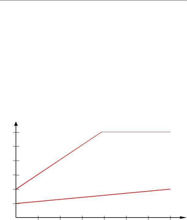
the interrelation may be seen on graphic below. |
3'000
2'500
2'000
1'500
1'000
Basic tone pitch 1000Hz
500
Basic tone pitch 500Hz
The tone increases rapidly, even at little Vario increase.
Setting = 9
The tone increases only slowly, even at high Vario increase.
Setting = 2
0 |
2 |
4 |
6 |
8 |
10 |
12 |
14 |
SinkF
Basic Tone pitch Tone pitch at starting Sink tone. The Sink tone is continuous and is heard with deeper sound pitch at increasing sink speed and is slowly increasing in frequency when approaching rising air. The basic tone pitch of sink acoustics may only be set equally to the basic tone pitch for climb acoustics.
The Sink tone may be switched-off by briefly pressing the 

 key, and can also be switched-on again; then the analog Vario display would show the relevant threshold. Starting point of sink tone is set Main Setup Menu User Settings Vario Acoustics
Sink tone threshold
.
- 15 -

Operating Manual Flytec 6020
damp
Dampening The Variometer value is recalculated every 0.2s. In case of rapid Vario changes and setting of quickly increasing tone pitch, this may possibly result between two calculation phases in a
quite important modification of tone frequency. The ear perceives this incidence as a kind of fast “piano effect”. In order to diminish this effect, a damping feature may be fitted. Then rapid tone pitches are honed in the frequency. As a result, the Vario sound has a smoother response.
Pit. |
|
|
|
|
|
|
|
|
|
Beep intervall |
|
See graphic |
|
|
|
|
|
||
30 |
number |
|
|
|
|
|
|
|
|
|
beep tones |
|
|
|
|
|
|
|
|
25 |
per second |
|
|
|
|
|
|
|
|
|
|
|
|
|
|
|
|
|
|
20 |
|
|
|
beep tone short interval=7 |
|
|
|||
15 |
|
|
|
|
|
|
|
|
|
10 |
|
|
|
|
|
|
|
|
|
|
|
|
|
|
|
beep tone long interval =1 |
|
||
5 |
|
|
|
|
|
|
|
|
|
|
0 |
2 |
4 |
6 |
Vario |
8 |
10 |
12 |
14 |
Main Setup Menu User Settings Vario-Acoustics Sink tone threshold .
The Sink tone is continuous and is heard with deeper sound pitch at increasing sink speed and is slowly again increasing in frequency when approaching rising air.
Starting point |
The starting point of sink acoustics can be selected just as in |
|
|
climb acoustics. The threshold can be set by use of the S T |
|
|
arrow keys. |
|
|
During flight the Sink tone can be switched-on or switched-off |
|
|
by short pressure on the |
key. Then one can see upon |
|
switch-on the selected starting point in the analogue Vario |
|
|
scale. Switch-off is just confirmed by a short beep of the key. |
|
Main Setup Menu User Settings Vario-Acoustics Vario Climb threshold
Starting point In order to avoid the climb acoustics get started with immobile aircraft, for ex. at take-off area, or at only slight climb, the climb acoustics starting point can be set in the range from 0 cm/s up to 20 cm/s. Depending on the selected filter type, when climbing, the Vario shall now activate vigorously or slowly
- 16 -

Operating Manual Flytec 6020
Main Setup Menu User Settings Variometer Basic filter .
Filter type |
Depending on the condition, if the air is quiet or turbulent, |
|
one can select 5 different filters. See „Analog Vario“ page 14. |
The warning sound for Stall alarm is a pitch tone of medium height with a very fast interval rate and always at full volume level of 100%.
All sound effects described here above may be heard in simulation mode.
2.3 Speed
The 6020-GPS provides a speed measuring inlet for a wind wheel sensor. This item displays the true flight speed through the air and starts correct measuring above 1 km/h, it is therefore also very convenient for determination of the wind strength at take-off. The
speed measuring inlet can be adjusted by implementing a correction factor. Factory setting is always 100%.
Main Setup Menu User Settings Speed Settings Wind Wheel.
This correction is helpful, if the speed sensor can not be fitted at optimum.
The wind vane sensor measures the True Air Speed (=TAS).
Speed is displayed in digital mode.
2.3.1Speed without Speed Sensor
Frequently hangglider pilots fly without any speed sensor. In this case it is possible to present the GND-Speed as digital display within a freely selectable user field. The 6020-GPS calculates from GND-Speed, as well as wind direction and strength a computed air speed. However, this indication of air speed without speed sensor is
just an approximation to the effective air speed. This is in many cases sufficient to do certain assessments, e.g. if the goal can be reached or not. The data of wind direction and strength are established in this case by flying one or more circles. The instrument computes wind direction and strength from the disparity. It is recommended to pilot’s flying without speed sensor to fly from time to time an entire full circle in order to establish wind direction and strength. Due to the fact that the calculated air speed is related to the wind data present at the location where circling was effected, the calculated air speed is no longer valid under different conditions of wind data.
The air speed calculated without speed sensor is the True Air Speed. See Chapter 2.7.3 Wind direction and strength page 31.
2.3.2Stallalarm
This audible alarm is consisting of a deep tone with short beeps and always with 100% volume level. In Main Setup Menu User Settings Speed Stall speed it is possible to set the speed for activating the stall alarm, and likewise, the altitude can be set to the point from where up the alarm is active. If the stall alarm is set to the value of 0 km/h, the alarm is turned off.
Stallalarm is only enabled when wind vane wheel is inserted. Furthermore, it is only enabled between 15 km/h True Air Speed and the selected Stall speed.
2.4 Time of day and Date
Caution: time of day and the date do not need to be adjusted. They are taken automatically from the GPS-Receiver. However, any time zone difference from UTC (World Time) needs to be entered with a positive value if the time zone is located East of Greenwich, or a with a
- 17 -
Loading...