


Flytec 6030-GPS
6030 GPS
User Manual Firmware V 3.21
Flytec AG
Ebenaustrasse 18 , CH – 6048 Horw Switzerland
Tel. +41 41 349 18 88 – flytec@swissonline.ch - www.flytec.ch
1 / 62

Flytec 6030-GPS
Table of Contents
1
Introduction ..................................................................................................................................... 3
1.1 Keypad and summary of display screen ..........................................................................................................................4
1.2 User selectable Fields......................................................................................................................................................6
1.3 Entering Text ....................................................................................................................................................................7
1.4 Menu Sequence ...............................................................................................................................................................8
2 Displays .......................................................................................................................................... 9
2.1 Altimeter and Air Pressure ...............................................................................................................................................9
2.1.1 Altimeter A1, absolute altitude...............................................................................................................................9
2.1.2 Altimeter A2, relative height ................................................................................................................................10
2.1.3 Altimeter A3, cumulated height ...........................................................................................................................10
2.2 Variometer......................................................................................................................................................................11
2.2.1 Analogue Vario....................................................................................................................................................11
2.2.2 Digital Vario - average value or Netto Vario ......................................................................................................11
2.2.3 Acoustics and Volume Level ...............................................................................................................................11
2.3 Speed .............................................................................................................................................................................14
2.3.1 Vane wheel und dynamic air speed sensor.........................................................................................................14
2.3.2 Speed without Speed Sensor..............................................................................................................................15
2.3.3 Stall alarm............................................................................................................................................................15
2.4 Time of day and Date .....................................................................................................................................................15
2.5 Temperature...................................................................................................................................................................15
2.6 Navigation ......................................................................................................................................................................16
2.6.1 Assessment of Reception quality ........................................................................................................................16
2.6.2 Compass and Flight Direction .............................................................................................................................16
2.6.3 Track and Bearing ...............................................................................................................................................16
2.6.4 Waypoints and Co-ordinates ...............................................................................................................................17
2.6.5 Flying Routes.......................................................................................................................................................20
2.6.6 The Competition-Route for record- performance- and competition pilots ...........................................................22
2.6.7 Relocating Thermals............................................................................................................................................27
2.6.8 XT Error, Crosstrack Error................................................................................................................................28
2.6.9 Airspace (CTR - Restricted areas) ......................................................................................................................28
2.6.10 Air space - enter – alter - Delete..........................................................................................................................29
2.7 Flight Optimisation..........................................................................................................................................................31
2.7.1 Ground Speed - (Speed over Ground) ................................................................................................................31
2.7.2 Head-, Cross or Tailwind: the Wind component..................................................................................................31
2.7.3 Wind Direction and Wind Speed .........................................................................................................................31
2.7.4 Glide ratio ( = L/D ratio ) .....................................................................................................................................31
2.7.5 Speed to Fly for best Glide..................................................................................................................................32
2.7.6 L/D req to goal = required Glide ratio to last WP of a Route ...............................................................................33
2.7.7 Alt a. Goal (In total required Height to the Goal of a Route)................................................................................33
2.7.8 McCready-Ring....................................................................................................................................................33
2.7.9 Average Thermal Climb.......................................................................................................................................34
2.7.10 Flight time ............................................................................................................................................................34
2.8 Battery - Management....................................................................................................................................................34
3 The Setting Menus........................................................................................................................ 36
3.1 User Settings..................................................................................................................................................................36
3.2 Instrument Settings ........................................................................................................................................................37
3.3 Manage Memory ............................................................................................................................................................38
3.4 Factory Settings (Specific instrument settings) ..............................................................................................................38
4 Data transfer ................................................................................................................................. 38
4.1 Flight-Memory and Flight-Analysis .................................................................................................................................38
4.1.1 Graphic Display of flights in Map format..............................................................................................................40
4.2 Data exchange via PC....................................................................................................................................................41
4.2.1 Flight instrument Options.....................................................................................................................................42
4.2.2 Waypoints and Routes ........................................................................................................................................42
4.2.3 Airspace (CTR)....................................................................................................................................................42
4.3 Transferring new Software to the FLYTEC 6030 GPS...................................................................................................42
5 Miscellaneous ............................................................................................................................... 43
5.1 Optional SW - Packages (additional Software) ..........................................................................................................43
5.2 Landing in water .............................................................................................................................................................43
6 Simulation ..................................................................................................................................... 43
7 Disclaimer of Warranty:................................................................................................................. 44
8 Technical Data .............................................................................................................................. 45
9 Appendix............................................................................................................................................. 46
9.1 Altimeter .........................................................................................................................................................................46
General inforation......................................................................................................................................................................46
9.2.1 Gross- Netto - Vario.............................................................................................................................................46
9.3 Speed .............................................................................................................................................................................47
9.3.1 True or Indicated Airspeed - TAS or IAS.........................................................................................................47
9.3.2 Stall Alarm ...........................................................................................................................................................48
9.4 Navigation ......................................................................................................................................................................49
9.4.1 Reception quality of GPS ....................................................................................................................................49
9.4.2 Accuracy of GPS Altitude ....................................................................................................................................50
9.5 Flight Optimisation..........................................................................................................................................................52
9.5.1 Polar curve and Speed to Fly ..............................................................................................................................52
2 / 62

Flytec 6030-GPS
9.5.2 Travel optimised Speed to Fly according to McCready.......................................................................................53
9.5.3 Final glide calculation ..........................................................................................................................................56
9.5.4 Safety altitude (Alt a. BG)...................................................................................................................................59
9.5.5 Final glide calculation over several Waypoints....................................................................................................59
9.6 Flight memory and IGC File ...........................................................................................................................................59
9.6.1 Content of IGC File..............................................................................................................................................59
9.6.2 New Regulation for Record flights or decentralised Competitions (OLC).................................................................61
9.6.3. Evidence of flights - Security against Manipulation .............................................................................................61
9.6.4 Digital Signature and OLC-Registration ..............................................................................................................62
1 Introduction
Although it is perfectly possible, even as a first time user, to just switch-on the FLYTEC 6030
GPS flight instrument and go flying right away, we recommend to first familiarise with the
multifaceted functions of the instrument and to study this operation manual. We have seen to it
that the operation manual was kept as succinct as possible, also bearing in mind not to
bother experienced pilots with well known explanations. For all those who want to refresh
their basics, or those who want to learn details about the individual functions and their
background, we have included in-depth descriptions in the appendix. These parts are
referred to in the operation manual. The present user manual shall be made public on our
internet website under reference Service / Downloads / Manuals, in the same way as all the
other manuals of our flight instruments. It is only this publication which is valid in regard to
the latest status and is providing leads about innovations or technically changes. For this
reason we recommend to check our website service from time to time.
The operation program of the FLYTEC 6030 GPS is stored in a so-called Flash-Memory.
Upgrading your instrument’s software to the most recent version may be done from outside
by use of a computer, without any module replacement. The appropriate cable required is
included in the scope of supply.
As for any given electronic instrument, you should protect your FLYTEC 6030 GPS from
excess temperature, hard shock, dirt or water inrush. It is also recommended to mount a
radio-set antenna as far as possible from the flight instrument.
Please look at the illustration on the following page, study the explanations close to the
picture, and then, after having shortly read through the table of contents, go to the
explanations of the instrument’s functions. We introduce for the first time on flight instruments
two so-called software-keys on the FLYTEC 6030 GPS. These are the keys F1 and F2 of
which the function changes in accordance to the actual display mode. For example, after
energising the key F1 may stand for „next function“ and F2 for “adopt 1013hPA or GPS-
Altitude”.
However, in Set mode for waypoints F1 stands for "Insert WP" and F2 for "Delete WP".
The key’s signification is in each case shown on the display.
In order to present the manifold possibilities of the FLYTEC 6030 GPS and also for a better
understanding of gliding flight theory, a simulation mode is included in the FLYTEC 6030
GPS.
Using this feature, it is possible to comprehend artificially just about any situation
encountered during flight. The user may change various settings, such as Climb or Sink, Air
Speed or Speed over Ground, as well as the flight direction and observe their effects on the
other indicators, such as Speed to Fly, McCready-Ring, arrival altitude above goal, distance
to goal etc. The acoustics are also simulated.
3 / 62
Flytec 6030-GPS
f
f
f
r
f
f
f
T
r
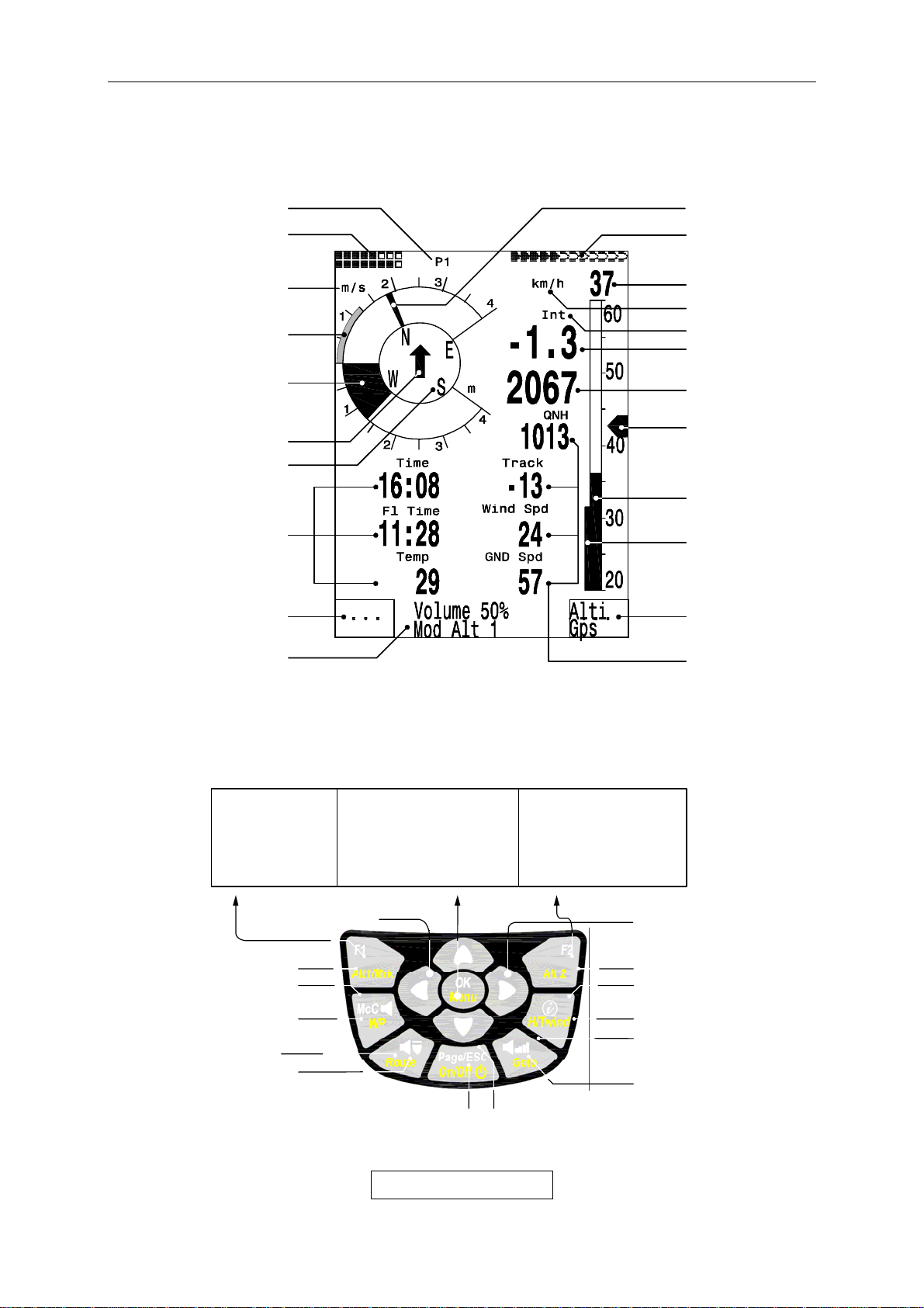
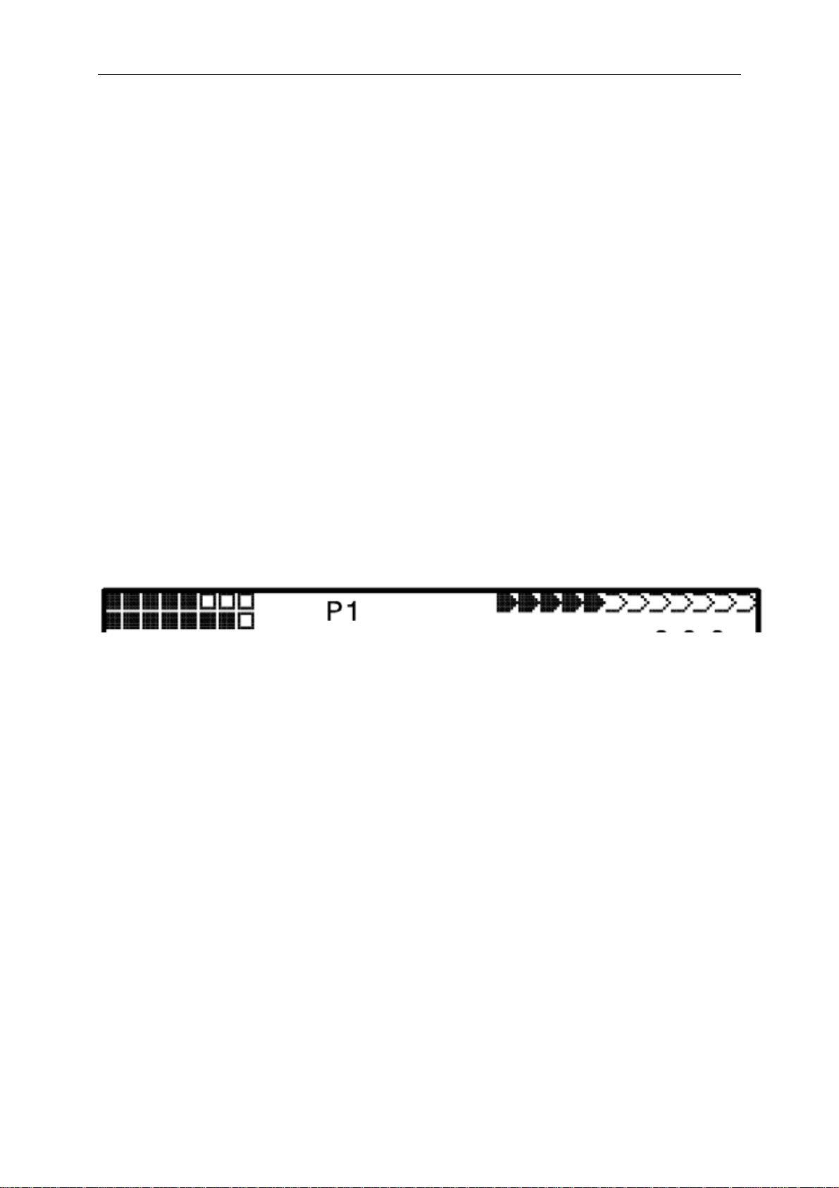
1.1 Keypad and summary of display screen
page numbe
battery status
ario unit
V
specific day
climb
Analogue
Vario
McCready pointer
GPS-DOP/
intens.
Satellites
Digital Speed
Speed unit
ariomode
V
DigitalVario
height
Direction to WP
user
Selectable
fields
Function o
Info line
Info
Speed to
fly
compass
Analog Speed
Stallspeed Limit
Function o
Key F1
User
line 2
fields
Arrow key functions in normal mode
Nxt ↓ ----
Fnc ↓ Mod A1↑↓ QNH/Gps
↓ Mod A2↑↓ SET0
↓ S.Thr –0.8 SNK OFF/ON
↓ HT auto Man Wnd
INFOFELD at Display
key F2
selectable
GPS-Receiv. On/Off
McCready Sound
On/of
Marker (stores WP)
Sink tone On/of
Routes-selection
Selection o
user selectable
fields
Instruments / GPS-Map
Display option :
at Menue mode
1 Step back
Standard fonts =short pressing
Boldface fonts = long-pressing
on/off Switch
(off=keep pressed for 3 sec.)
Change o
use
pages
volume
Menu
confirming
of actual
WP-selection
defined
Zero Alt A2
coordinates
4 / 62
Flytec 6030-GPS
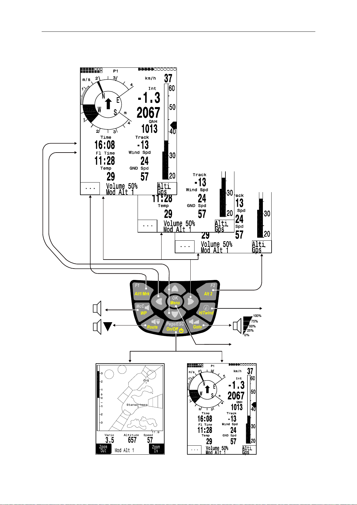
page1page2pag
f
f
f
g
Display indications defined by user
selecting o
user defined
fields
Soft-key F1
e 3
McCready sound
On / Of
sink-alarm
sink-tone On / Of
changing of user defined
fields
ENTER / confirmation
Soft-key F2
Info key
Normal: Coordinate
Map: CTR Info
Switchin
Instrument screen / Map Mode
5 / 62

Flytec 6030-GPS
FLYTEC 6030 GPS Switch-On and Off
The unit is switched on by pressing the key "Page/ESC On/Off ". To prevent inadvertent
switch-on, it has to be confirmed after the display message „really switch on ?“ by pressing
the key " OK ". For some seconds shall appear general data, such as serial no., pilot’s name,
SW-version, date, aircraft, and also the size of available memory for storage of waypoints
and CTRs (EEPROM). For switch-off you need to press the same key during 3 seconds and
to confirm the display question "really switch off ?” by pressing “OK”.
After ending a flight, the calculation of the digital signature can take up to 2 minutes. Please
wait until the message „Generating Digital Signature“ disappears and press once more the
key Page/ESC On/Off.
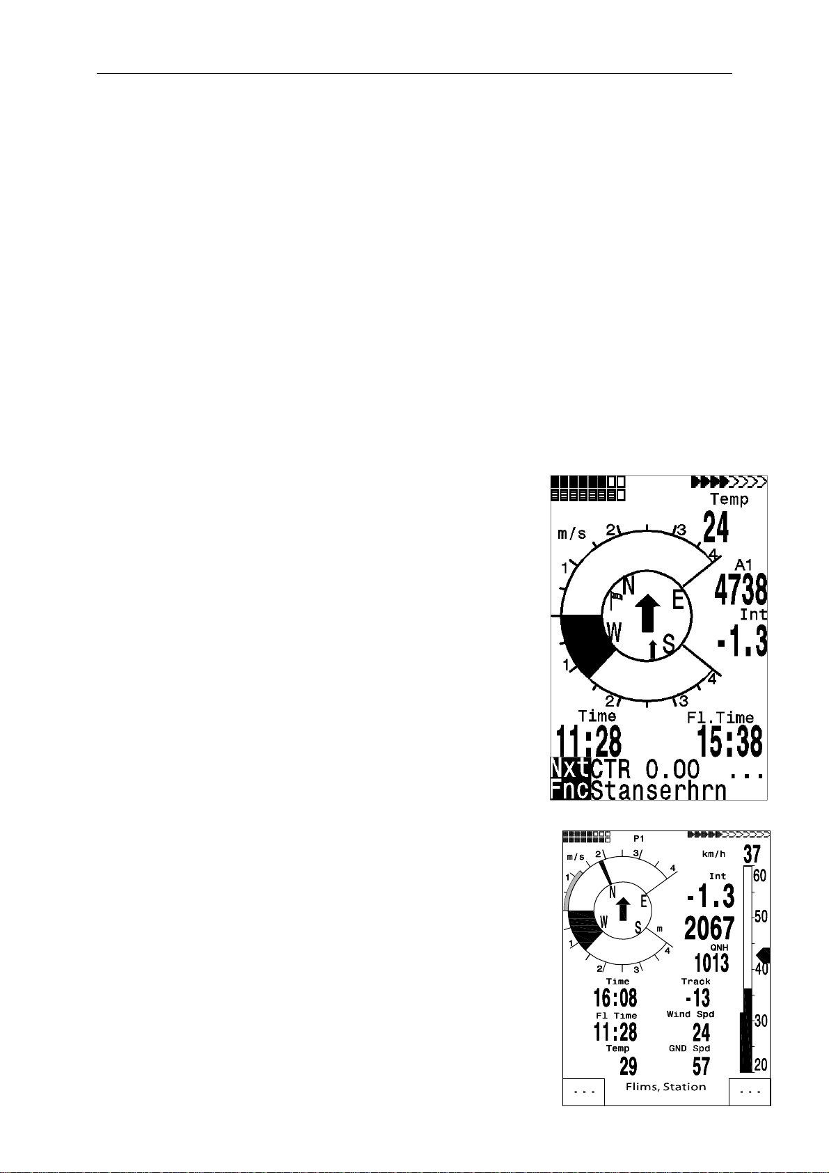
1.2 User selectable Fields
In the lower display part beside the compass rose there are 7 user selectable fields which
can be used to the pilot’s choice. In total about 27 selectable measurement data are
available. All user selectable fields can be set comfortably on the PC by use of the
freebie PC-Software Flychart 4.52 and are transferred via the PC-interface to the
instrument. In order to assign a field to a certain measuring press the key ◄. Explanation
of the respective display is provided with a black bar. Repeatedly pressing the ◄ key
switches to the next field. The ▲or ▼ keys enable you to assign for each field the following
measurements:
Caution: For security reasons it is not possible to change the assignment of user selectable
fields during flight.
Display remains empty
Time Time of Day 1.8.2
Flight time Flight time since take-off 1.8.3
Vario Digital Vario
Alt 1 Absolute altitude
Alt 1 ft Absolute altitude in ft
Alt 2 Reference altitude, may be set to 0 user-defined
Alt 3 Cumulated gain in height during the flight
FL (ft) Flight level in feet. Not alterable
QNH (hPa) Air pressure in Hektopascal 1.2
GND speed Speed over Ground * (= GS) 2.3
Air Speed Speed through the air 1.5
Wind Speed Wind Speed * 2.5
Spd-Diff Wind component (Groundspeed – True Air Speed) * 2.4
Track Flight direction (Course) * 1.8.4
Bearing Direction to selected Waypoint * 1.8.4
XT Error Crosstrack Error. Shortest distance to active leg of a Route.* 2.6.8
Dist to WP Distance to selected Waypoint * 2.9
Dist t. Goal Counted up sectors in front of the pilot up to the last WP 1.8.7
of a Route*
Dist. t Takeoff Distance from take-off position 2.6.6.1
L/D r. goal Glide ratio over Ground needed to reach goal over several
Waypoints in a Competition Route* 2.7.5
Dist to ∧ Distance to last Climb*
Dist to CTR Distance to next CTR 2.11
6 / 62

Flytec 6030-GPS
L/D gnd actual glide ratio over ground ( = Groundspeed/Sink)* 2.7.1
L/D air actual glide ratio ( = TAS/Sink) 2.7.1
L/D req required glide ratio over ground to reach WP * 2.7.1
L/D req goal required glide ratio over ground to reach Goal
Alt a. BG Safety altitude above the best glide path* 5.6
Alt a. Wp Arrival altitude above waypoint * (acc. to McCready) 2.7
Alt a. Goal Precalculated arrival altitude over the last waypoint of a Route * 1.8.8
Temp Temperature of circuit board 1.8.1
SMS p/t SMS pending/transmitted
* Display only active when GPS Receiver is energized.
If nothing is changed after having selected
a field, the instrument returns to normal
function after 10 sec. and the previous
display is shown again.
By pressing briefly thekey, a 2nd and
3rd page with each time 7 displays is
accessible. Choose
for selection of these displays with each
time 4 large fields, or 6 small fields.
In this case the compass rose is hidden,
but the big arrow pointing to the WP
remains visible.
We would like to assist the user by
providing some approved recommendations
for preset of 3 selectable field pages.
Some of the displays are so interesting that
we recommend to present these on each of
the 3 possible field pages always at the same places.
This would be for instance „Groundspeed“ or the wind component „Speed-Diff“.
Page 1) is called up, if the pilot flies without predetermined goal (thus without the “GoTo”
function) In addition to the displays mentioned before, also the fields for: Dist to ^; L/Dgnd;
Flight Time; Alt2 or Temp could be displayed.
Page 2) is used, if a waypoint (WP) to go for has been selected. Instead of the fields
suggested above, values for Dist to WP; Alt a. BG; Alt a. WP should also be displayed here.
Page 3) could be called up for the final glide to the landing area. Even if the pilot selects the
large data representation here, the most important functions should be displayed here,
such as the big arrow pointing to goal, and also Dist to WP; Spd-Diff; Gnd-Speed; Alt a BG;
and Alt a. WP.
Basic Settings / Userfields
1.3 Entering Text
It is possible to enter on certain fields, as for example pilot’s name, or in regard to waypoints
and Routes, the desired text on the instrument. However, this is quite complicated. It is much
more easier to carry out the text entry by use of the PC using the program Flychart 4.52,
and to transfer it to the instrument.
For entering Text proceed as follows, this example is given for a waypoint:
7 / 62

Flytec 6030-GPS
By using the keys ▲ and ▼ it is possible to select an individual WP and to alter it after
pressing the OK key.
The 1st letter of the WP name shall be flashing, again by using the ▲and ▼ keys the
required letter is selected; numbers, letters as well as a range of special characters are
available. By pressing the ► key the cursor moves to the next letter position etc. In this mode
the F1 key is used to switch between capitals and minuscule.
The F2 key is used to rub out one character. It is possible to enter max. 17 characters.
When the name has been entered completely, confirm by pressing OK.
1.4 Menu Sequence
Main Menu
Flight memory
Waypoints
Routes
Airspace
User Settings
Variometer
Basic filter
Digital Vario Integrator
Threshold last Climb
Specific Day Climb
Variometer Acoustics
Acoustic settings
Threshold ascent acoustic
Threshold Sinktones
Speed
Speed mode
Sensor setting Pitot
Sensor setting wind vane
Stall Speed
TEC Total Energy Compens.
Flight Memory
Recording Auto/Man
Recording interval
McCready
Polar Curves
Pilot’s name
Type of aircraft
Aircraft ID
Manage Memory
Delete all flights
Delete all WP&Routes
Delete all Airspace data
Formatting the Memory
Simulation
Instrument Settings
Display contrast
Language
Battery type
Time zone
Units
Coordinate format
Bluetooth
SMS
Additional Software package
Package 00
Airspace (max 20) 01
Airspace (max 300) 02
Bluetooth SMS 03
Package 04
Package 05
Package 06
Package 07 - Factory settings
8 / 62

Flytec 6030-GPS
2 Displays
2.1 Altimeter and Air Pressure
A barometric altimeter calculates altitude from the present air pressure of the atmosphere.
Air pressure will decrease at increasing height. Due to the fact that air may be compressed,
the pressure decrease is not linear, but indeed exponential. The basis for altitude calculation
in aviation is an international formula which defines a standard atmosphere.
.
In the CINA- standard atmosphere the basic pressure on sea level is 1013,25 hPa
(Hektopascal) at a temperature of 15°C. Furthermore it defines a continuous temperature
decrease at increasing height of 0,65°C per 100m ascent. Therefore is binding: a barometric
aviation altimeter displays the precise altitude only if weather conditions are in exact
accordance to the standard atmosphere. In practice, such analogy is more likely to be the
exception!
Air weight and pressure are strongly influenced by air temperature. If temperature deviates
from standard atmosphere, the display of altitude calculated as per the international formula
is no longer correct. The altimeter displays during summer, when temperatures are higher,
indeed altitude parameters which are too low, and during the winter it is exactly the contrary!
Flying at lower temperatures is effectively done at lower altitude, and at higher temperatures
flight altitude is higher than the altimeter displays! The deviation of 1 °C per 1000 height
meters induces approx. 4 m error. This empirical formula is valid for up to 4000m!
If you fly during summer through 2000 height meters in an air mass being too warm by 16 °C
compared to standard atmosphere, the altimeter will then display 2 x 4 x 16 = 128m
difference in altitude under real height! Based upon the internationally determined altitude
calculation with standard values, this display error caused by air temperature shall not be
rectified by the instrument.
Air pressure changes in relation to weather conditions. In order to compensate for display
fluctuations, an altimeter always needs to be gauged. This means that the altimeter has to
be set precisely before take-off for any flight to a well-known altitude value. Caution:
the atmospheric pressure may change during the timeline of one day up to five Hektopascal
(for ex. cold front). As a result this is after all the equivalent of more than 40 meters height
difference.
There is another possibility to gauge the altimeter which is to enter the current QNH pressure
value. The QNH (Question Normal Height) applied in aviation matches the current local
air pressure, as it would be at sea level, so that the altimeter would indeed display 0m.
Due to this procedure the local pressure data recorded by the various measurement stations
is area-wide comparable, irrespective of the geographical height.
The QNH-value is subject to be continuously updated and may be read in the flight weather
report, or required by radio from airfields, or by enquiry on the internet.
The instrument provides 3 altitude displays.
2.1.1 Altimeter A1, absolute altitude
A1 is always the altitude above sea level (large display in upper part of display screen).
Altitude A1 is originally set by the manufacturer to show the correct user’s altitude,
if air pressure at sea level is 1013 hPa. Bearing in mind that this only happens infrequently,
9 / 62

Flytec 6030-GPS
the displayed altitude A1 should be gauged before each take-off to the actual, true height
at location. Pressing the ▲key will increase the displayed altitude, the ▼ key will decrease
altitude. The info line will show:
pressure display will also change. This air pressure value (QNH) is always related to sea
level height.
If the user does not know the altitude of his present location, he may obtain the data
by fading in the „User Field QNH“ and, using the arrow keys, by changing the altitude
value until the QNH matches the actual QNH as per weather forecast.
If the GPS system receives satellites, the GPS-altitude is applied as Alt1 by pressing
the F2 key. If there is no GPS reception, it is possible to set the altitude Alt1 by use
of key F1 to a value which complies to QNH pressure of 1013 hPa. If the altitude of
any given landing place is set to 0m, after take-off there will be of course always be
displayed the altitude above this location. The related air pressure (QFE) is the real
present air pressure at this place in hPa, which differs of course from QNH according
to the difference of altitude, as QNH is the pressure at sea level.
2.1.2 Altimeter A2, relative height
A2 (in the user selectable fields) is a reference height, it can be modified by use of the
arrow keys ▲▼. Long pressure on F2/Alt2 generates the display „Mod A2 ↑↓“ in the
information line. By use of the arrow keys it is possible to set the height difference, or
to set with brief pressure on F2/SET 0 the height difference to 0.
2.1.3 Altimeter A3, cumulated height
A3 (in the user selectable fields) sums up the total height meters gained during one flight.
For thermal flights this height is dependant on flight time. If several pilots complete the same
flight task, then the one who had the least gain in height (A3) would have been the best to
accomplish the task.
Within the user selectable fields it is also possible to choose altitude A1 in ft. This
information is important when in contact with the air traffic manager in Restricted Areas.
Furthermore it is possible to choose FL (ft) in the user selectable fields. This is an
altitude display in feet for the flight level. This feature is not adjustable and is always
related to a QNH value of 1013 hPa (air pressure at sea level). This display is particularly
important for pilots of microlight aircraft to whom is assigned a Flight Level by air trafficcontrollers during flights in Restricted Areas.
A2, A3, FL or QNH may be selected within the user selectable fields.
(see under user displays).
Mod Alt1 ▲▼(= modify Alt1). Due to this adjustment the air
10 / 62
Flytec 6030-GPS
2.2 Variometer
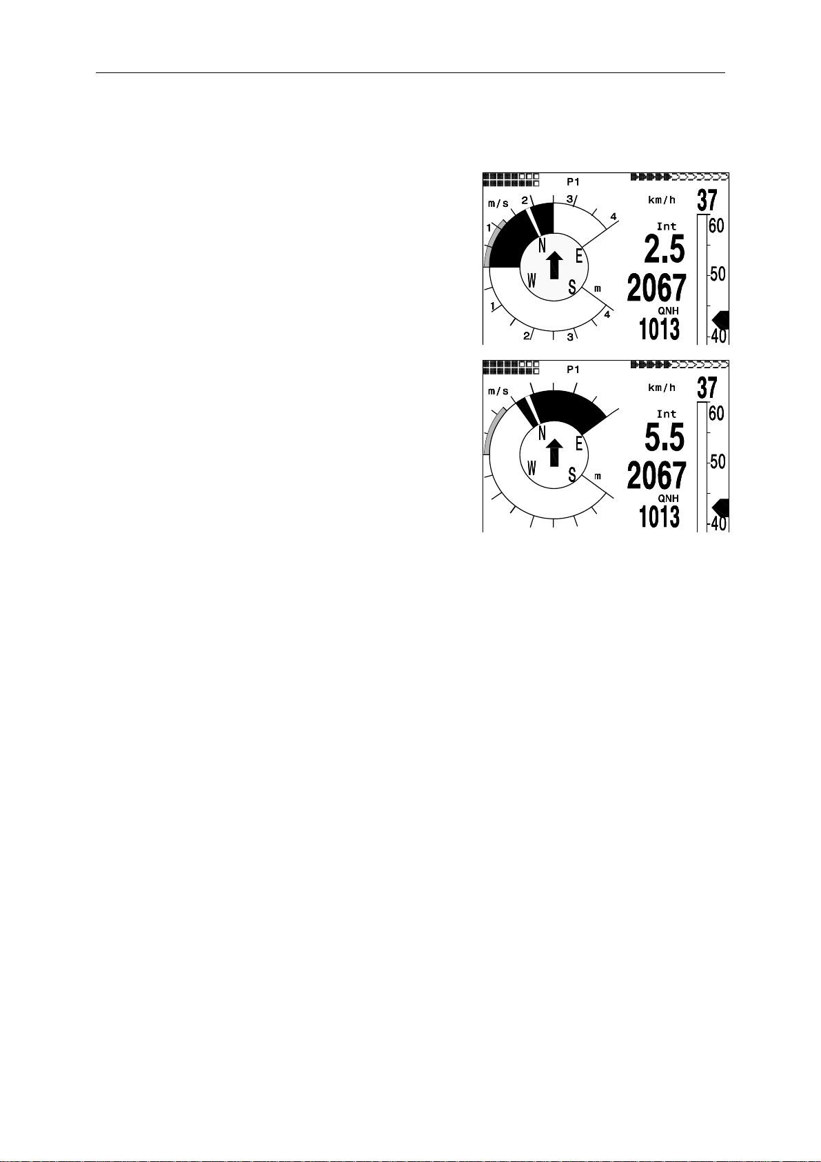
2.2.1 Analogue Vario
The most important indication for a non-motor driven
aircraft is without any doubt the Variometer.
It displays the vertical speed in meter/second and
informs the pilot about the actual climb or sink rate.
It is only possible for the pilot by using the vario (and
its accompanying acoustics) to determine the most
efficient thermal climb, and in the opposite situation, to
recognize when he is sinking too rapidly in descending
air and should leave them at best speed.
The scale of the analogue display is 0,1 m/s. The
range of the first scale extends from 0 up to +/- 4 m/s,
thereafter the scale display switches automatically and
the range of the second scale extends from 4… 8 m/s.
6
5
The time constant of Analogue-Vario is factory set
to 1,2 s. In the Set-Mode (Vario-Speed-Average)
this value may be adjusted between 0,6 … 3 s.
In case of short time constant the Vario is very bumpy,
with a long time constant it will be somewhat sluggish.
5
6
2.2.2 Digital Vario - average value or Netto Vario
The Digital Vario has a scale of 10 cm/s and a vast measuring range of up to +/- 100 m/s.
It is therefore also appropriate to display the vertical speed for parachutists during the jump.
It may be provided with a time constant from 1 … 30 s in the Set-Mode under "Variomode"
as average value-Vario (also called integrating Vario). This may be useful to observe the
average climb inside a rough thermal.
The Digital Vario may also be operated as Netto Vario which displays the condition of
ambient air. Please also read 9.2 Vario for this topic.
In addition it is possible to set the Digital Vario in such a way that it operates during the climb
as integrating Vario, and during sink as Netto Vario. (Set-Mode / Basic Settings/ Variomode )
2.2.3 Acoustics and Volume Level
Brief pressing of the key ; /Goto will increase volume level each time by 25%. The adjustable
sound levels are: 0 - 25% - 50% - 75% - 100% - 0. The selected value is displayed on
the info line.
Automatic volume control: with the basic setting levels 25 50 u. 75 % volume level will be
slowly increased automatically, once the airspeed exceeds 40 km/h. However, it is impossible
for the volume level to exceed 100%.
The following settings are possible to be entered in the Set-Menu under " Basic Settings /
Vario tone ".
Ascent Freq.: the ascent acoustics start at a climb rate of 0,1 m/s. This is a frequency
modulated interval tone whereby the pitch and frequency increase rhythmically at increasing
climb rate. The pulse/pause ratio is 1:1.
7
8
8
7
11 / 62
Flytec 6030-GPS
–
–
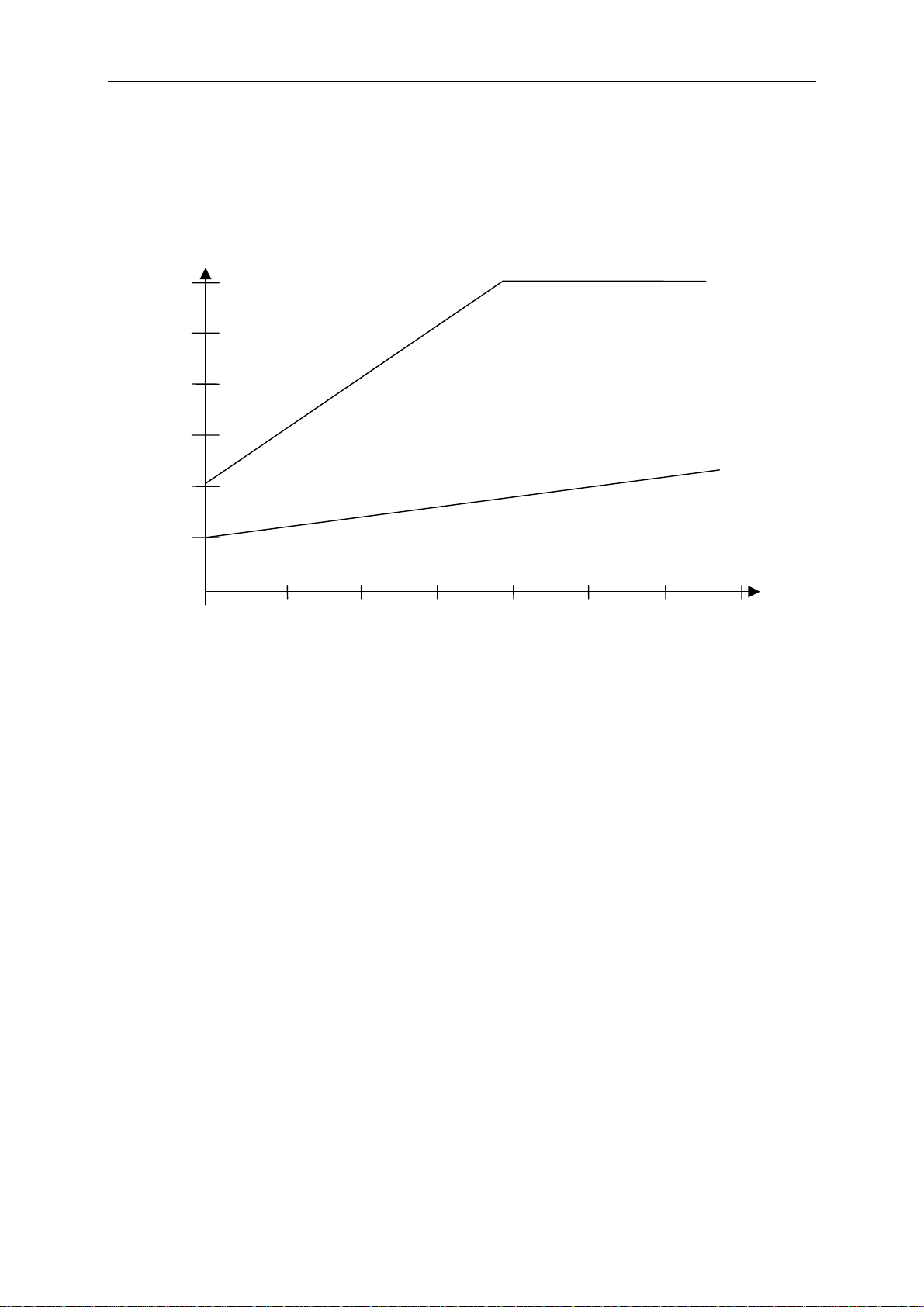
AscentF
Basic Tone pitch Is the frequency audible at starting climb tone.
Factory setting 1200 Hz
Modul.
Increase Tone pitch The interrelation may be seen on graphic below.
Factory setting = 4
30 00
Ton
Frequen
Hz
25 00
Increasing tone -fast
=9
2 00 0
15 00
Basi
1000 z
Increasing tone -slow
=2
100
500
Basi
500 H z
0 2 4 6 8 10 12 14
SinktoneF
Basic Tone pitch Tone Pitch at starting Sink tone. The Sink tone is continuous
and is heard with deeper sound Pitch at increasing sink speed,
and is slowly increasing in frequency when approaching rising
air. The basic tone Pitch of sink acoustics may only be set
equally to the basic tone Pitch for climb acoustics.
The descent tone may be switched-off by briefly pressing
the key ; /Route and also be switched-on again; then one
would hear the dedicated tone and the analogue Vario display
would show the relevant starting point. The starting point of
sink tone is set in Set-Mode under "Basic Settings / Sink Tone
threshold".
damp
Dampening The Variometer value is recalculated every 0.2s. In case of
rapid Vario changes between two calculation phases,
it may result in a quite intense variation of frequency. The ear
perceives this incidence as a kind of fast „piano effect“.
In order to diminish this effect, a damping feature is fitted.
The relevant factory setting is 8. Rapid tone pitches are honed
in the frequency. As a result, the Vario sound is then smoother.
Beepch
Beepchoose At setting of „0“ the single beep of climb acoustic has a fixed
frequency; at setting “1” the climb acoustic also changes during
the beep.
Vario
12 / 62

Flytec 6030-GPS
Pitch
Beep interval See graphic. The beep interval is also called „Pitch“.
Factory setting = 3
Pitch
Frequenz
Hz
Piepsintervall - kurz
Piepsintervall - lang
=7
=1
Vario (m/s)
In Set-Menu „Basic Settings“ the following threshold settings may be entered:
Sink tone threshold.
Starting point The starting point of sink acoustic can be selected just as in
climb acoustic.
Vario Audio threshold,
Starting point In order to avoid the climb acoustic get started on the ground
with immobile aircraft, for ex. at take-off area, the acoustic
starting point can be set in the range from 0.02m/s up to 0.2m/s.
The warning sound for Stall alarm is a pitch tone of medium height with a very fast interval rate
and always at full volume level of 100%. (Please also read Stall-alarm chapter 2.3.3 page 15)
When gliding with McCready sound activated, the tone to be heard is corresponding to the
active McCready locator. Because of the pulse/pause ratio being here 1:4, it is not possible
to confound this sound with the vario ascent tone.
(Please read 0 - Travel optimised Speed to Fly acc. to McCready).
The warning tone for negative McCready-Ring values is a deep tone with rapid
interval rate which tells the pilot: „fly faster immediately“.
All types of sound effects described here above may be heard in simulation mode.
13 / 62

Flytec 6030-GPS
2.3 Speed
Apart from Vario and altitude the flight through the air (= airspeed) is indeed one of the
decisive messages. By use of a precisely indicating speedometer it is not only possible to
increase air safety, but also to enhance the efficiency on long range flights.
On non-motor driven gliders the speed to fly and the McCready theory, as well as the Netto
Vario may only be operated correctly, if the precise flight speed through the air is made
known.
Due to the fact that the average flight speed of hang gliders and fixed-wing aircraft has been
increased over the past years, the service life of the utilised vane wheel speed sensors was
decreasing to the same extent. Double speed signifies 8-times wear out of the sensor.
2.3.1 Vane wheel und dynamic air speed sensor
For this reason the FLYTEC 6030 GPS is provided with two independent speed sensor
connections.
1. For paragliders the wind wheel sensor is maintained. Advantage: it displays the true
flight speed through the air and starts correct measuring above 1 km/h, it is also
very convenient for determination of the wind strength at take-off.
2. For hang glider pilots there is a dynamic air speed (pitot tube) connection which is
suitable to display speed data up to 300 km/h, it starts display only from 20 km/h.
If required, the pitot tube may be lengthened by use of flexible hose and be
positioned on a turbulence-free spot of the glider.
In particular the pilots of rigid-wing aircraft will appreciate in regard to flight safety
that on the analogue speed scale the gap of current speed to Stall speed is very
clearly perceptible.
There are correction factors dedicated for both speed connections. The factory setting is
always 100% for each of them. Basic Settings / Airspeed correct vane or ..pitot, within this
setting the Pitot-Sensor may be completely switched-off.
Depending on flight speed resp. of approach angle it is possible to measure differences of
airstream between the wing top side and wing lower side. Above top side the airstream
always higher, at lower side it is more slowly. This difference is also called rotation stream.
It is the reason why the speedometer displays during slow flights too little speed and during
fast flights too much speed.
In order to compensate for this fault, it is possible to set under Airspeed Offset an offset
of several km/h. It is highly recommended in any case to re-determine the correction factor
afterwards by realising a measuring flight.
The wind vane sensor measures the true air speed (=TAS).
The dynamic air speed sensor however measures the indicated air speed (=IAS).
In case you do not know the difference between these two terms, then please read
article 9.2 of the appendix.
Speed readings are analogue, as well as digital. The user may select in Setup-Menu Basic
Settings / Speed mode, if he prefers to read as True or as Indicated Air Speed. Regardless
of which sensor is used, on the FLYTEC 6030 GPS always both speed readings are present.
In the same Menu item paraglider pilots may set a display range being lower by 10 km/h
on the analogue scale 20 … 60 km/h. (Factory setting here is 30 … 90 km/h).
14 / 62

Flytec 6030-GPS
Upon exceeding the analogue speed scale it shall not be shifted, in this case the upper
position digital display is only valid.
The FLYTEC 6030 GPS is presented in 2 versions:
• Hangglider version with pitot pressure sensor or
• Paraglider version without pitot pressure sensor.
Also on the hangglider a connected wind vane sensor shall always overwrite the pitot tube
display. The wind vane sensor is always given priority.
2.3.2 Speed without Speed Sensor
Frequently hangglider pilots fly without any speed sensor. In this case a calculated
airspeed is determined automatically. This display is the result of a vectorial addition of
wind and ground speed. Caution: wind force data and direction are only available after
the pilot has flown a full circle and they are updated after each new full circle. The
duration of one full circle should be min. 12 seconds or more. The feature Calculated
airspeed may be displayed as user selectable field.
2.3.3 Stall alarm
This Alarm is audible, consisting of a deep tone with short beeps and always with 100%
volume level. In Set-up Menu Basic Settings / Stall speed it is possible to set the speed for
activating the stall alarm, and likewise, the altitude can be set to the point from where up the
alarm is active. If the stall alarm is set to the value of 0 km/h, the alarm is turned off.
The trigger point for the stall alarm is always linked to the indicated airspeed. At higher
altitudes, i.e. in thinner air, the alarm shall be activated earlier (i.e. at higher flying speed)
than for ex. at sea level. It is easy to check this effect on the analogue speed scale by
simply setting altitude A1 for several 1000m higher.
Please read the related article of the appendix.
2.4 Time of day and Date
Caution: time of day and the date do not need to be adjusted. They are taken automatically
from the GPS-Receiver. However, any time zone difference from UTC (World Time) needs
to be entered with a positive value if the time zone is located East of Greenwich, or a with a
negative value, if it is at the West. Time zones with 0.5h UTC Offset are also adjustable.
Notice: all internal calculations of the instrument are made in UTC. The local time is just
used as „Time“ display and calculates simply the UTC plus or minus the UTC Offset.
The local time is also binding for the take-off time at Competition Routes.
2.5 Temperature
The instrument needs a temperature sensor for the temperature compensation of sensors,
as well as for the automatic display contrast control. Temperature reading is possible in
degree Centigrade or Fahrenheit. ( Set-up-Menu/ Basic-Settings/ Units )
Caution: the sensor measures the circuit board temperature. The inside temperature of the
casing may be higher than the ambient air temperature, especially when the instrument is
exposed to direct sunlight.
15 / 62
Flytec 6030-GPS
2.6 Navigation
Navigation activities without operating GPS-Receivers is unthinkable these days.
Indeed a chain of satellites is orbiting the Globe. It provides the possibility to determine
world-wide one’s own position very precisely, if min. 4 satellites are received simultaneously.
2.6.1 Assessment of Reception quality
The FLYTEC 6030 GPS is fitted with a 16-channel GPS-Receiver which is featured with
lesser power consumption and also a significantly shorter satellite detection time.
Precision is between 7 to 40m. As an average one may assume approx. 20 m.
Normally the instrument recognises its position under unobstructed view condition after
maximum 1 to 2 minutes. If the receiver is switched-off for a short time (less than 2 hrs.),
the time for new position finding is less than 10 seconds as a rule. Buildings, mountains or
thick forest affect reception quality of the receiver. Therefore, you should always look for the
best possible visibility around you and the antenna in the casing should point upwards
if applicable. In particular when mounted on the steering holder of the hangglider,
we recommend not to have the instrument fixed under the pilot’s head on the middle of
the basis, but indeed sideways. In this position the FLYTEC 6030 GPS should not have more
than 45° deviation from horizontal position so that the antenna points upwards.
Because the receiving strength of the satellite signals is only approx. 1/1000 of mobile
radios, these radio sets and other disruptive factors (like notebooks) should be operated as
far away as possible from the FLYTEC 6030 GPS.
The number of received satellites is shown on the upper right side of the bar scale. The
longer the bar, the more precise is the reception quality.
As soon as the instrument has sufficient GPS reception after energising, the date and time
of day is recorded into the internal memory. This action is signalled by the instrument with a
slight beep tone.
2.6.2 Compass and Flight Direction
In contrast to a normal magnetic compass which is oriented to the magnetic lines of force of
the Globe, the GPS compass can show direction only when the user moves about.
However, it has the advantage that it is not subject to any grid deviation and does not show
any deviation as a result of iron or any magnetic material either. Its zero point always
corresponds with true geographic north (0 or 360 degrees).
The course that is the flight direction (= Track), is calculated from a series of positions. If the
user remains stationary at the same location, then the course (track) and compass needles
are undefined. The exact course, this is the direction in which the user travels over ground, is
always at the top of the compass, but can also be read in the display “Track”. When circling
in a thermal the compass rose only appears to turn; in reality the needle does not move; it’s
the casing along with the aircraft, which moves around the rose.
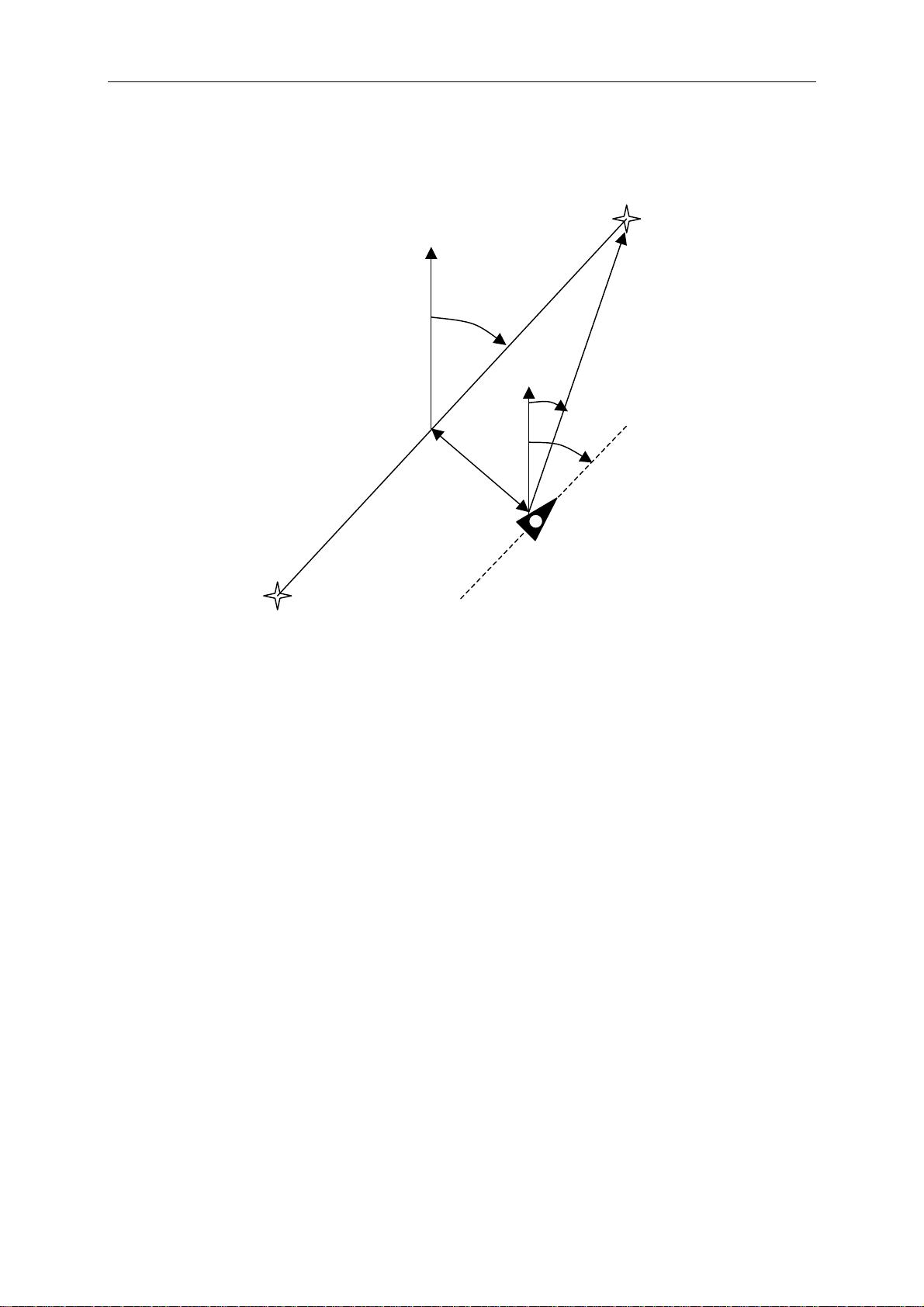
2.6.3 Track and Bearing
In accordance to previous GPS receivers, the Track is also defined as the route of
movements of the aircraft over ground. Geographic true North is always 0 or 360 degrees
(East = 90, South = 180, West = 270 degrees).
16 / 62
Flytec 6030-GPS
r
r
The bearing is the direction (according to the system described above) to a selected
waypoint seen from the viewer.
Caution: Track or Tracklog is also called the sequence of recorded positions during one
flight.
NORTH
Course
Distance
DTK
Bearing
Course
erro
Crosstrack
erro
Track
Speed
WPT1
2.6.4 Waypoints and Co-ordinates
A waypoint is any single point on the earth’s surface that you would like to go to.
The FLYTEC 6030 GPS can save up to 200 different waypoints. Each waypoint can have up
to 17 characters, e.g.
to enter the altitude, i.e.
“Fiesch Airfield”. In determining the waypoint, it is also necessary
“1123” meters (always above sea level). We now only need the
position of waypoint on the earth’s surface. For this purpose the FLYTEC 6030 GPS utilizes
the most international and commonly used geographical map system named WGS84
(World Geodetic System 1984). This reference system assumes that latitude is measured
from the equator (0 degrees) to the North Pole, 90 degrees North, and to the South Pole
- 90 degrees South. Longitude is measured from the Greenwich zero meridian ( near London),
East is counted positive and West is negative up to +/-180°.
Setting of coordinates is also possible in UTM and Swiss Grid. The FLYTEC 6030 GPS also
understands waypoints entered according to the previous norm, introduced by Flytec:
3 letters and 3 numbers. Example: FIE112 indicates a waypoint with the name FIExxx
and an altitude of 1120 meters above sea level.
In
Basic Settings / Coordinate Format the data entry format is selectable between:
1) Degrees Minutes Decimal places of minutes (dd°mm.mmm)
2) Degrees Minutes Seconds (dd°mm’ss”)
3) Degrees Decimal places of degrees (dd.ddddd)
4) UTM ( a grid with a 1km raster in both and N-S and in E-W direction )
5) Swiss Grid
Basically one should always try to use No. 1) (=factory setting) because only this format is
using exactly the same calculation format as the GPS receivers do. With all the other formats
rounding errors could sum up to 20 m.
WPT2
17 / 62
Flytec 6030-GPS
Beside the WGS84 map system many countries have their own map system of reference.
Due to misinterpretations caused hereby, we have erased this selection from the
FLYTEC 6030 GPS. Only the WGS84 Geodetic system is in force, which is the only one
being homologated for record flights by FAI and OLC.
2.6.4.1 Waypoints, alter, Delete or insert
In this position of Set-Menu the waypoints may be managed. Waypoints may also be set
comfortably on the PC by use of the „Flychart 4.52“ PC-Software and be transferred
via the PC-interface to the instrument. After briefly pressing the OK key the display
shows the list of saved waypoints. In case this list contains more than the visible 8 WP,
Then a down arrow Ð at the right lower edge of the list warns that more pages are to follow.
To scroll down to the next page, press the ► key, now WP 9 … 16 are displayed etc.
Using the keys ▲ and ▼ it is possible to select
an individual WP and to edit it after pressing
the OK key.
The 1st letter of the WP name will blink, again
with the ▲ and ▼ keys the required letter is
selected; there are numbers, letters, as well as a
set of special characters to choose from.
By pressing the ► key you move forward to the
next letter etc. With the F1 key you may shift
between capitals and small letters. With the F2
key one single character is deleted (Rub out).
You can enter a maximum of 17 characters.
Once the name has been entered completely,
confirm by pressing OK .Now the waypoint
altitude will blink, requiring any alterations.
With the ▲▼ keys the altitude value is entered
and confirmed by pressing OK. Now the position
of WP is next. First the latitude is entered in
degrees and confirmed with OK, after that the
minutes and then the decimals of the minutes.
The same procedure is applied for the Longitude. Holding the key down for a longer
moment,
changes the values to be set faster.
Delete Waypoints:
The selection of WP’s to be deleted is effected with the ▲ and ▼ keys.
Pressing the F2 key (Del WP) enables the delete function, for data safety the FLYTEC 6030 GPS
is asking again: “Delete Waypoint?”. The reply “Yes” or “No” is at choice, but it is also possible
to discontinue the deleting procedure by use of the Esc key and return to one level before.
Insert Waypoints:
Pressing the F1 key (Ins WP) enables this function. Entering waypoint names, altitude and
position is operated following the same scheme as described above. After confirming all
entries with the OK key, the new WP is inserted at the end position of the list. (There is no
alphabetical sorting). In total 200 WP may be saved in the FLYTEC 6030 GPS.
Caution: After entering the new waypoints, (for ex. for a new Route entry) these can be used
only if in between with Page/ESC you have switched back to the normal flight mode.
In addition, the Route into which the new waypoint should be inserted must not be active.
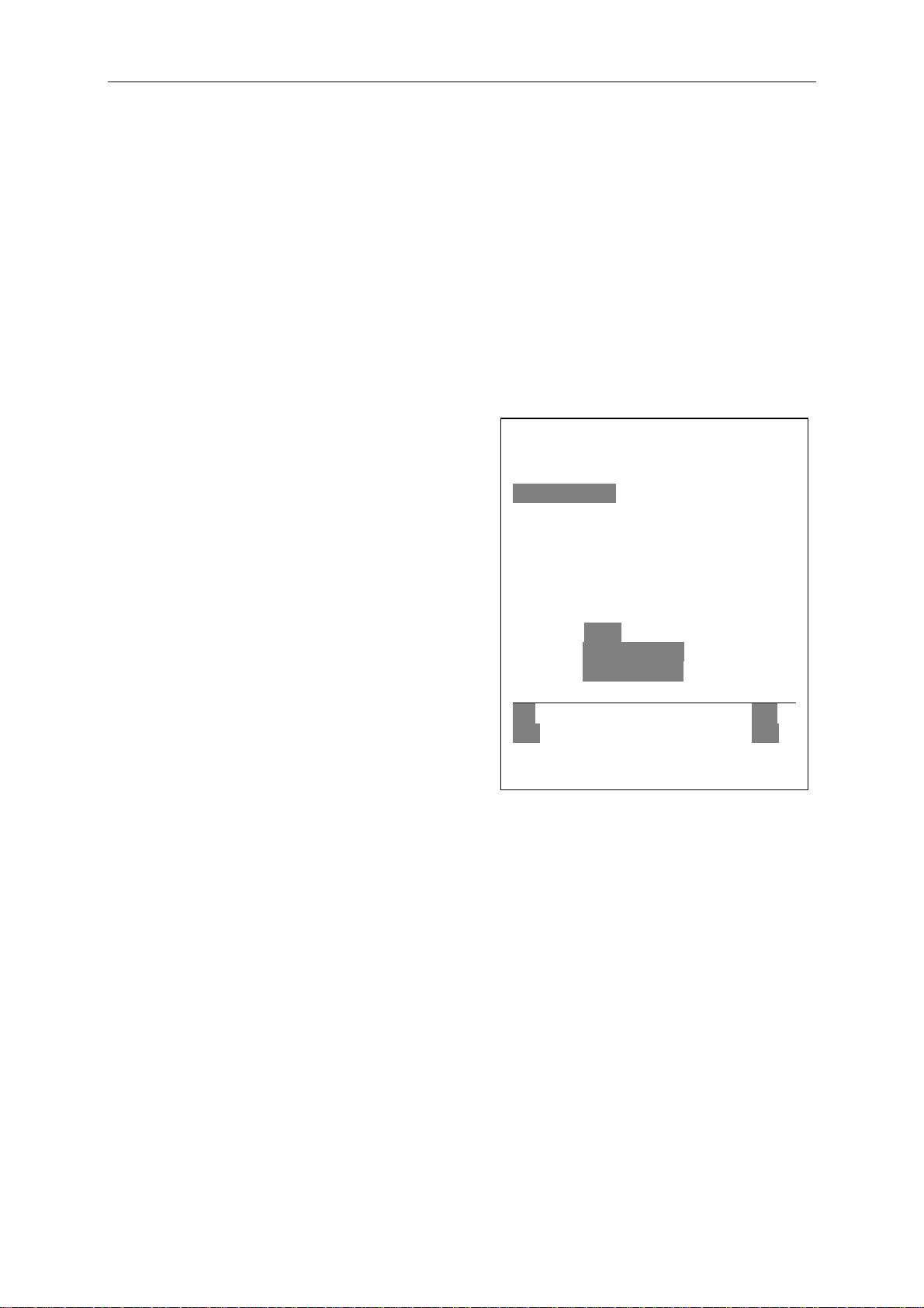
Waypoints
----------------------------------------------Flytec
Flims, Station
Calanda, Felsenb.
CrapSognGion
Cassons Grat
--------------------------------------------⇓
Used Waypoints
Fiesch
Alti 1048
Lati N 46’ 24.446
Longi E 08’ 08.264
-----------------------------------------------
Ins Del
WP WP
18 / 62
Flytec 6030-GPS
Therefore, first change into route selection by prolonged pressing of the ;/Route key and
with the help of the F2 key (Cancel Route) deactivate the Route.
2.6.4.2 Display of actual Coordinates
If the FLYTEC 6030 GPS receives satellites by GPS-Receiver, the actual position is
displayed by pressing the Info key in the instrument’s information field. After 20 sec.
the previous display screen will automatically reappear. This function is useful in relaying
your location after landing to some person who will retrieve you from there.
2.6.4.3 Memorising the actual position
It may happen from time to time that the current position should be saved as waypoint.
For this purpose the McC ; /Mark key should be pressed during 3 seconds. In response
a double beep will chime and the momentary Coordinate shall be saved in the memory
as a waypoint.
As the WP name the FLYTEC 6030 GPS uses the letter M (for marker) and after it the actual
date and the time of day in UTC.
Example: M.22.04. 11:16:49 stands for 22nd April at 11 hrs. 16 min. 49 seconds (UTC).
Naturally this WP name may be changed later into a more meaningful name, for ex.
Fiesch Airfield".
2.6.4.4 Distance to Waypoint (Dist to WP)
Only in case a waypoint has been selected manually
or automatically with the "Goto" function, the horizontal
distance seen from the viewer to the waypoint is displayed.
The scale is 10 m ( for distance under 10 km ) otherwise 0,1 km.
Please read: 2.6.4.5 Goto – Function
Also when the WP is used as turning point in a competition,
it is always the distance to the centre of the cylinder which
is displayed.
2.6.4.5 Goto – Function
Prolonged pressure on the ;/Goto key switches the lower
half of the instrument into the ‘Goto’ mode. This function
allows you to search for a waypoint stored in the memory of
the FLYTEC 6030 GPS and to choose it for a flight to goal.
At the same time the next 5 waypoints are listed in the order
of
shortest distance to the user. The 1
name indicates the distance in km. The 2nd number shows the
direction (=Bearing) from the actual position to WP.
After pressing the F1 (Displ.AIti.) key the precalculated arrival
altitudes to the 5 WPs are shown instead of distance.
In practice there are 5 final approach (final glide) calculations to
the WPs active at the same time. Caution: It is only the WP to
which the pilot is directly flying to ( ±/20 ° ) , for which the wind
component is also taken into account for the calculation.
The F1 (Displ.Dist.) key also switches back to the distances.
If a waypoint has been selected with the▼ key, it can be accepted
by the Ok key. The Goto function can be deactivated with the
F2 (Cancl Goto ) key.
st
number behind the WP
19 / 62

Flytec 6030-GPS
If a strong cross wind is encountered on the way to goal, the right correction angle can be
found as long as one carefully changes the direction of flight against the wind, until the
directional pointer in the compass rose points directly upwards. In that way it is ensured that
the flight path over ground is in a straight line to goal and thereby the shortest one. The well
known “pursuit curve”’ is thus avoided.
Within the user-selected displays may be set in the upper part for instance Speed over
Ground, distance to waypoint and the pre-calculated arrival altitude (Alt a.WP). This height
could also correctly be designated as altitude above the fastest possible glide path to goal.
The pre-calculated arrival altitude is assuming that neither up-wash nor down-wash zones
are present in the glide path and that the wind remains constant. Nevertheless a certain risk
is definitely present. The wind component
pressure of the Info/H/Twind key and the arrow keys up/down.
Please read in this regard:
2.7 Flight optimization
Also amongst the user-selected fields there is the safety height above the best glide path
(Alt a. BG). While circling upwards before approaching the WP, this height will show 0 when
the pilot should be able to reach the goal by flying at the best glide speed. Every meter
above that means a greater safety margin. As soon as „
positive values, both these fields are displayed inverse. At good ascent in the thermal
it makes sense to start the final approach, if „
The Alt a. BG then shows how much ‘security height’ the pilot will have available to use if
necessary in order to compensate for unexpected sink. Under no circumstances should the
pilot go ahead and fly towards goal if the „
Reaching goal would then be impossible without finding thermal lift on the way.
2.6.5 Flying Routes
A route is an arrangement of various waypoints. Of course, the waypoints used on a route
have to be saved in the unit’s memory. Similar to the Goto-Function the pilot should fly
from WP to WP in a travel optimized mode, which means that with help of the McCreadytheory he will be able to complete his task within the shortest possible time. If inside the
Goto-Function the next waypoint needs to be selected from a list each time by prolonged
pressing of the Goto key, when flying Routes it is possible to switch forward by briefly pressing
the key ▲ (next WP) or ▼ (previous WP ). Selection of a Route is effected by long pressing
of the ;▼/Route key. Each Route should also be assigned a name, for ex. „ Cassons Grat“.
It makes sense to store many well-known thermal sources as waypoints along a route. The
pilot does not have to feel compelled to reach these waypoints, at times he may be high
enough to jump a waypoint on a route, while at another time he may have already found the
hoped for thermal one or more kilometers before reaching the waypoint. Of course there is
still the option of looking up other, possibly closer, waypoints without leaving the current
Route by using the Goto-function. Altogether, the FLYTEC 6030 GPS can have up to 20
Routes created. The one and same waypoint can be used more than once along a Route,
and the same waypoint may occur on other Routes as well. Once a WP has been used
along a Route, it can no longer be deleted from the WP list.
Copying of a Route in a Competition-Route: For this purpose the
item Routes should be called in Set-Mode. By using the ▲▼ keys the required Route is to be
set and completed by pressing the McC ; /WP key. The FLYTEC 6030 GPS inquires: „Copy
to Competition-Route?“ which could then be confirmed by “Yes”.
Spd-Diff may be preset manually by prolonged
ALT a.WP“ or „Alt a.BG“ show
Alt a.WP“ displays zero.
ALT a.BG“ shows zero or minus sign numbers.
240 153
20 / 62

Flytec 6030-GPS
Direction arrow to the next but one Waypoint:
In the middle of the compass rose a thick black arrow points to the next waypoint.
The arrow to the next but one waypoint is a shaded, transparent arrow underlays the
black arrow. This feature makes sense in particular in competitions, if the pilot knows
in advance in which direction he should continue to fly after reaching the cylinder
circumference.
2.6.5.1 Routes - Set – Delete – Alter – Copy
Marking the Menu item Routes in Set-Mode (Main Setup-Menu ) gives access to this Menu
item. Routes may also be set comfortably on the PC by use of the „Flychart 4.52“
PC-Software and be transferred via the PC-interface to the instrument.
After further pressing the OK key the Routes saved in the FLYTEC 6030 GPS will appear
(max. 20 Routes) From these you can select one of the routes to be deleted by using the
and
keys; press F2 (DeI.-Route) to delete or OK key to alter. However, by pressing the Fl
key (Ins. Route) a new route can be created
Setting a new Route
After pressing the F1 key (lns.Route), at first a name has to be entered for the Route. The
cursor will blink on the first letter of the word “Xxxxx”. By using the
each to the desired letter. By using the
and so forth. By pressing the OK key you conclude the entry of the route name. At this time
the individual WPs need to be added. After pressing the F1 key (lns.Wayp) the list of
available WPs will appear in the bottom half of the screen in alphabetical order. At the same
time you will see the request: “Select Waypoint No1.” Again by using the
search for the 1
upper half of the screen. By pressing the F1 key (Ins.Wayp) again, you can select the second
waypoint and add it to the Route with OK etc. The highlighted waypoint (offset in black) in the
Route is always the last one entered, which means that the function “lns.WP” will set the next
WP to be entered after the one highlighted in black. If you want to insert an additional
waypoint after WP1, then you highlight WP1, press the F1 key (lns.WP); then the request
“Select Waypoint No 2” appears.
If you notice, for example, that Waypoint No. 4 must be changed, then you select and delete
it and insert a new one after the existing WP3 by pressing F1 . Again the list of available
waypoints appears and the request “Edit Waypoint No 4”. After selecting and pressing OK,
the old waypoint is replaced by the newly chosen one.
If you want to delete a waypoint from the Route, it is marked and completed by pressing the
F2 key (Del. Wayp) The WP is then deleted from the list without any additional prompt.
Altering a Route
You select a route to be changed with the
name is changed first. If this is not what you want, then it is sufficient to press OK again in
order to get access to the waypoints. As described in the last paragraph, additional WPs can
be added or deleted now.
Deleting a Route
You select the route to be deleted with the
(Del.Route). For data safety the FLYTEC 6030 GPS inquires once again: “Delete Route?”
which should be answered with Yes or No.
Copying a normal Route as FAI-Route
st
WP and it is added to the Route by pressing OK. This is indicated in the
key you proceed to the second letter, change it,
or keys and confirm with OK. The Route
or keys and confirm by pressing F2
and keys you alter
or keys you
21 / 62

Flytec 6030-GPS
Each one of the existing Routes may be copied into the memory of FAI-Routes. For this
purpose the required Route is to be marked and completed by pressing the McCr;/Mrk key.
Please note that after this entry the start cylinder, radii and start time need to be set
separately, because all cylinder radii are reset to the default value of 400 m.
2.6.6 The Competition-Route for record- performance- and competition pilots
In contrast to the routes described above, the FAI-Route has waypoints which are mandatory
to be reached; for example turning points in competition or record flights. The regulation,
which only recently came into effect in documenting distances flown, waives the complicated
and often difficult to interpret photographic documentation with photo sectors; but it rests fully
on the recording of GPS-Receiver position data (Tracklog points).
It is only when flying Competition Routes that the pilot will be warned by an acoustic alarm
when crossing the circumference of a turn point cylinder or when entering / leaving the start
cylinder and the unit switches automatically to the next WP. Call-up of the Competition Route
is effected by prolonged pressing of the ;▼/Route key and confirmation by “OK” key.
For setting and altering of FAI-Routes please read under: 3.5. Competition-Route Set –
Alter – e
Instead of the previous photographic sectors the pilot only needs to reach a predetermined
distance to the turning point. It is also called the entering flight into the cylinder. This distance,
or cylinder circumference may be set in the Setup-Menu/ Routes/ Competition-Route separately
for each waypoint in the range of 20 m up to max. 200 km. Within the
default or factory settings a cylinder circumference of 400 m is preset.
Setting of the differing cylinder radii, of start time, the flight task (= Entering or Exiting the
start cylinder) is effected upon data entry of the Competition-Route.
See also: 3.5 Set, alter and delete Routes
Because the GPS-Receiver of the FLYTEC 6030 GPS
identifies its new position every second, it takes only
this one second to inform the pilot about his crossing
of the turning point cylinder circumference or that it is
time to leave the start cylinder. In this case a long,
unmistakable tone sounds during 2 seconds and the
instrument switches automatically to the next WP of
the Route. Independent of what recording interval
for storage is used during a standard flight, it is
anyway guaranteed that several track log points when
crossing the cylinder circumference are saved at one
second intervals in the memory of the FLYTEC 6030
GPS.
Usually the start cylinder is in first position of the
Competition-Route. (However this is not mandatory).
If during setting or changing the Competition-Route
after marking a waypoint the key McC ; /WP is
pressed, the letter “S” for Start-Cylinder appears behind the WP name. The “S” disappears
if the same key is pressed again.
Only if a WP is marked with “S” it is necessary to set also a Start time and as task:
ENTER or EXIT and the number of Startgates, as well as their chronological interval.
The example illustration on the right shows the possible start time to be set for 12:30,
12:45 and 13:00 h. If no WP is designated as Start-Cylinder, the pilots are not bound to
COMPETITION-ROUTE
Fiesch 1.20 S
Flims, Station 0.40
Calanda, Felsenb. 0.80
CrapSognGion 0.40
Cassonns Grat 0.40
-------------------------------------Waypoint 1/5 in Route
Fiesch
Total Distance: 49
Radius (m) 1200
Starttime: 12:30 +15min
Startgates: 03 EXIT
--------------------------------------
Ins. Del
Wayp. Wayp.
22 / 62

Flytec 6030-GPS
observe a start time and the automatic switch over to the next WP is effected as soon as the
pilot is inside the cylinder.
If however in a competition a start cylinder is predetermined, the valuation starts as soon as
the start time is reached under these conditions:
Startmode EXIT: if the pilot is inside the cylinder and start time has been reached
Startmode ENTER: if the pilot den crosses the start cylinder from outside to inside
Task: EXIT Cylinder
The „WP reached“ signal will be given as soon as the start time is reached and the
pilot is inside the start cylinder. It will also sound if the start time is positive and the pilot
crosses the start cylinder circumference from outside to inside. In both cases the next active
waypoint will be enabled, in this case WP2. All calculations and the direction arrows are now
related to WP2 and the next turnpoint will become active (in this case WP2). All calculations
and the direction arrows are now with respect to WP2.
If the pilot decides to take the next start gate, he must press the Prev WP ▼ key. (Select
this Menu with prolonged pressing on McC ; /WP). The instrument then enables WP1 again
and will increment the start time by the preset difference. When the last start gate is reached,
the start time will no longer be increased after pressing of „Prev. WP ▼“.
Caution: for EXIT cylinder it is required that the first waypoint after the start cylinder is
outside of the start cylinder!
Task: ENTER Cylinder
WP2
WP1
Exit
WP1
ENTER
WP2
WP3
WP3
23 / 62

Flytec 6030-GPS
The “WP reached” signal will be given, as soon as the start time is positive and the pilot
crosses the start cylinder circumference from outside to inside. In this case the next active
waypoint will be enabled, in this case WP2. All calculations and the direction arrows are now
related to WP2
If the pilot decides to take the next start gate, he may press the Prev WP ▼ key. (Select
this Menu with prolonged pressing on McC ; /WP). He may carry out this operation
regardless if he is inside or outside of the start cylinder. The instrument then enables WP1
again and will increment the start time by the preset difference. When the last start gate is
reached, the start time will no longer be increased upon pressing of „Prev. WP ▼“.
Caution: for ENTER cylinder it is required that the first waypoint after the start cylinder is
inside and usually in the center of the start cylinder!
During a flight the pilot can see at the Info display via Count-Down how many seconds /
minutes are left before the opening of the Start line. At the same time he can read in the
display „Dist to WP“ if he is inside or outside of the start cylinder.
It is also possible during Competition-Route by pressing the
forth between previous and next WP. This is useful when a pilot, after having left the start
cylinder, has decided to fly back and to restart at a later time.
It is also possible by use of the Goto-key (prolonged pressing) to call-up additional waypoints
(thermal sources), sorted according to their distance from the pilot. The WPs being part of
the Comp.-Route are marked with an asterisk in the displayed list; this means it is mandatory
that they must be approached. Even in case a WP not belonging to the Route has been
called-up, the alarm remains enabled when entering the cylinder of the WP belonging to the
Route. With the F2 key it is possible to toggle back and forth between the WP of the
Competition-Route and the other WP.
After completing a flight task, the WPs belonging to the Comp.-Route will be listed in the data
transfer to a PC under the header of the IGC file. A corresponding PC program can also
check if the assigned task was completed correctly.
In order to comply to IGC Regulations, there are newly entered into the IGC-file in addition to
the turning points also the „Take off“ and the „Landing point“.
When setting up a Competition-Route without a start cylinder, i.e. without a start time, the
automatic switch over to the next WP is effected, as soon as the pilot is inside the 1. cylinder
radius. So it makes no sense to choose the “Take off” place for the 1
immediately after receiving satellites the instrument switches over to the next WP.
The following shortcuts are certainly helpful in this context:
McC ; /WP : Next Prev. ▲▼ WP = next or previous waypoint
Info/Htwind: HT man. ▲▼ = Manual or automatic entry of Wind component
(Head-Tail-Wind)
F2/Alt2: Mod Alt2 Modify altitude Alt2; or set to 0 with F2
keys to toggle back and
st
WP because
24 / 62

Flytec 6030-GPS
25 / 62

Flytec 6030-GPS
26 / 62

Flytec 6030-GPS
2.6.6.1 Competition-Route Set – Alter – Delete
Even so a Competition Route is treated differently than a usual Route during flight and also
data transfer, there is no difference when setting or changing it. The route can be set up with
the help of the keypad or can be transferred from the PC. This is particularly useful for
Competitions when in a short time the flight tasks on the basis of turning points have to be
distributed error free to many pilots. The Competition Route can be altered, however its
name cannot be deleted.
Each one of the other existing Routes can be copied to replace the Competition Route by
pressing the McC ; / WP key. This same key is also used to assign to one WP the status of
start cylinder. After pressing the “OK” key the start mode (ENTER or EXIT), the cylinder radii
and the start time are to be set. It is possible to use the same waypoint several times (e.g.
the goal and the landing place) with different radii.
2.6.6.2 Dist .T. Cyl. Distance to radius of a waypoint cylinder in a Competition Route.
This field displays the distance to the radius of the actual waypoint cylinder. This is
particularly helpful at start cylinder, but also during flight this display may help.
2.6.6.3 Dist. to Goal (Total distance to the Goal of a Route)
In this field there is displayed during flight the sum of the legs lying in front of the pilot. He
thus knows at any moment, how much km still are in front of him until completion of the task
WP1
WP2
Wind
Direction/
Strenght
Goal
Start
2.6.7 Relocating Thermals
With weak or widely dispersed thermals this function helps
to relocate any lost thermals. A small arrow pointing up in
the compass rose shows the direction to the last thermal
with at least a 1 m/s climb. If this arrow is
at the top of the display then you are flying towards the
thermal; however, if this arrow is in the lower part of the
display, you are flying away from the thermal.
If you want to utilize this function, then the indicator
"Dist. to ^" should be activated in the user defined fields.
This value indicates the distance from the pilot to the last
Thermal.
27 / 62

Flytec 6030-GPS
2.6.8 XT Error, Crosstrack Error
This field indicates the shortest distance (perpendicular related to the Earth) to the active leg
of a Route.
The accuracy of the indicated value depends on the length of the active leg. The largest
Inaccuracy arises in the centre between start and the next WP, if one is very close to the
track (the angles become very flat). With 50 km distance between start and WP the
inaccuracy in the centre can reach up to 400m. Positive values are displayed if one is
on the right of the track, negative values on the left of the track. Even if one has flown over
the next waypoint, the distance to the straight line is shown. (see position 3).
2.6.9 Airspace (CTR - Restricted areas)
Usually airspace areas are bordered by straight lines, but also circled zones or mixed from
straight lines and arc segments may be used. Basically each instrument 6030 already
contains on delivery a preloaded CTR, which is the CTR Innsbruck, and which may be
altered to one’s own discretion. As an option with costs the activation of 20 or even 300
CTR’s may be effected (please ask the instrument’s manufacturer).
CTR's can be entered into the instrument either manually in Setup mode / Lufträume, or
more easily by use of a PC program, e.g. Flychart 4.52 which is available on our homepage.
Within the menu item Extras / Fluginstrument Optionen / Lufträume it is possible to select
and load CTR’s for transfer onto the FLYTEC 6030 GPS. In the same way it is possible
with the „Maxpunkte“ program to transfer individual CTR’s from PC to the FLYTEC 6030
GPS.
The procedure for manually setting, altering and deleting CTRs is operated according
to the same system which is used for setting, altering and deleting waypoints and Routes.
More related information is provided in par. 2.6.4.1 of this manual.
In the user selectable fields the field „Dist. to CTR“ indicates the shortest distance to the
next CTR, if this distance is less than 50 Km.
As soon as the distance to CTR falls short of a warning limit to be set in Setup Mode (factory
setting = 2000m, dist. Flychart 200m), this distance is displayed additionally on the graphic
map screen, as well as on the standard flight display in the Info line. CTR 0.75 Km
Negative value
Start target
Pos 3
Waypoint
positive
value
28 / 62

Flytec 6030-GPS
W
p
If the pilot is inside of the CTR, then Dist. to CTR is always indicated as 0.
For each CTR is assigned a name and a comment to be freely edited by the pilot. The
names of the five next airspace CTR’s may be shown with the Map Mode key. The
comment may be used to inform the pilot during flight about the upper or lower border limits
of the CTR. The sequence of these CTR’s corresponds to the distance from the momentary
position. A second pressing on the Info/Htwind key removes this information.
We invite pilots who want to make use of CTR’s to contact us. They will get, dependent on
the serial no. of the FLYTEC 6030 GPS, a 5-digit activation code for entry into the
instrument.
Procedure for entry of activation code:
Setup Menu / Optional SW-Packages - OK
Set marking on CTRs (Restr. Areas) ▼ - OK
Enter activation code ▼ ▲ - OK. One starts best with the ▼ arrow.
If the code number was correct, the instrument confirms with : Package released
2.6.10 Air space - enter – alter - Delete
The Menu Airspace is placed in Main Menu -> Airspace.
Name of CTR
As type the following elements may be selected:
Point: endpoint
Centre: centre of arc segment
Startboarder: start point of arc segment
Stopboarder: endpoint of arc segment
Circle: centre of the circle plus Radius
Personal comment
Restricted areas
=====================
CTR1 Alpnach
TMA 1 Alpnach
TMA 2 Alpnach
=====================⇓
Ctr1/3
CTR 1 Alpnach
Höhe FL130
arning Dist.[m]: 200
No Elements:8
Ins Del
Ctr Ctr
Warning distance
Information to
number of end
oints / elements
29 / 62

Flytec 6030-GPS
Example:
counterclockwise
5 Stopboarder
Dir -
7. Point
6. Point
3 Center
4 Startboarder
Dir -
2. Point
1. Point
To enter arc segments, then the following sequence must
be observed:
Long, Lat centre;
Long, Lat start point of arc segment;
Long, Lat end point of arc segment;
Rotational direction (+clockwise, - counterclockwise)
For circles the centre and the Radius are sufficient
Long, Lat of centre;
Radius in km
1. Point
2. Point
6. Point
CTR1 Alpnach
=================
Point 1/7
Point 2/7
Center 3/7
Startb. 4/7
Stopb. 5/7
Point 6/7
================⇓
Point
Lat N 47’00.783
Lon E008’17.917
Ins Del
Ele
Ele
30 / 62

Flytec 6030-GPS
2.7 Flight Optimisation
2.7.1 Ground Speed - (Speed over Ground)
The GPS-Receiver calculates its new position once every second. Speed over Ground is
derived from the distance between these positions. This value belongs to one of the most
important pieces of information at all, because only from the difference between Airspeed and
Speed over Ground it is possible to reach conclusions about the wind’s influence. Therefore the
Speed over Ground should also appear on all display screens of user selectable fields. With a
paraglider (without pitot pressure sensor tube) the calculated airspeed may be shown in a user
selectable field, if no wind vane sensor is plugged in.
The same applies if in the Basic-Settings/Airspeed correct pitot the function of the pitot
sensor has been deactivated. ( Use Sensor ? = No ) The calculated airspeed (Calc. Airspeed)
is the result of a vector operation of wind and ground speed.
For measuring the wind it is necessary to fly several circles.
2.7.2 Head-, Cross or Tailwind: the Wind component
During a goal flight or in calculating a final glide, it is not really the absolute value of wind,
the wind component, i.e. the difference between Ground speed and Air speed, that is
decisive. In most cases the wind does not blow directly from the front or from behind, but
somewhat from the side. If this wind component “Spd-Diff” (in the user defined fields) is
positive, then the pilot will fly with a tail wind and the glide ratio over the ground will improve.
If it is negative it contains at least a part of head wind and the glide ratio over ground will
decrease. The FLYTEC 6030 GPS takes the wind anyway into consideration during target
flight or when calculating the final glide.
In order to find the right correction angle when a strong cross wind is present, please refer to
the section 2.6.4.5: Goto – Function.
The calculated wind speed can be displayed in a user selectable field.
If the windsock indicating the wind direction covers the wind symbols N E S W, then for
reasons of clarity the corresponding letter below shall disappear!
2.7.3 Wind Direction and Wind Speed
It is very important to know the wind in direction and
strength, especially in case of an out landing. The wind
strength can be selected within the user defined fields.
For this purpose it is necessary to fly one or two complete
circles as steadily as possible. Whilst circling, the FLYTEC
6030 GPS determines the direction of least speed over
ground, and checks also synchronously if in opposite
direction there might be the fastest speed over ground.
The calculation of wind speed is the result of difference
between Airspeed and Groundspeed. Wind direction is shown in the compass rose
at the position from where the wind is blowing by a small windsock symbol. During the
landing approach this symbol must always be at the top.
2.7.4 Glide ratio ( = L/D ratio )
By definition, the glide ratio is calculated by taking the horizontal distance traveled and
dividing it by the height which was lost.
31 / 62

Flytec 6030-GPS
A
t
If instead of the horizontal speed is taken the speed through the air, the error is 2%
at glide ratio 5 and just only 0,5% at glide ratio 10. This small inaccuracy is insignificant
and may be disregarded
Glide ratio values achievable in steady air with following aircraft:
Paraglider
Normal
Paraglider high-
performance
Hang glider
Normal
Hang glider High
Performance
Fixed wing
aircraft
5 - 7 7 and more 8 - 11 11 - 14 15 and more
Within the user defined display fields the glide ratio may also be selected.
The following facts are applicable:
Glide ratio though the air:
L/D
= TAS/Sink True airspeed divided by Sink
air
Glide ratio over Ground :
L/D
= GS/Sinken Speed over Ground divided by Sink
gnd
Required glide ratio over Ground from momentary position to selected WP .
L/D
= Distance to the WP / Height difference to WP
req
Example for explanation of glide ratio values
Best glide -start
931m above the
target
ct. heigh
956m
681m
Alt a BG
275m
Best glide 8
L/D req 5.7
2km
Akc. Distance to WP 5.45 km
2.7.5 Speed to Fly for best Glide
The thick arrow visible on the hand right side of the analogue speed scale informs the pilot
about the speed for best glide
, dependent on the polar, the wind and rising resp. sinking
of surrounding air. In Competition, a pilot will always fly faster than this speed indicator
is recommending, except when every meter of height is essential. Please also read under:
9.5.1 Polar and Speed to Fly. It is negligible whether the pilot has chosen to set the display
on true or indicated air speed, because the FLYTEC 6030 GPS shall indicate at any altitude
and steady air the same value for best glide. However for True Airspeed the speed
recommendation will increase gradually in accordance to increasing altitude. (Please
see also: 9.3.1 True or Indicated Air Speed – TAS or IAS.
32 / 62

Flytec 6030-GPS
t
2.7.6 L/D req to goal = required Glide ratio to last WP of a Route
This field displays the required lift/drag ratio over ground to the goal over several waypoints.
It helps to decide whether one can fly directly over several waypoints to the goal, or whether
one must gain height within a Thermal. The calculation does not take into account if there
is an area with higher geographical altitude than the direct line from current position to goal.
Distance is calculated as in 2.6.6.3. Dist to Goal (total distance to the Goal of a Route).
2.7.7 Alt a. Goal (In total required Height to the Goal of a Route)
This user field displays the calculated altitude above goal, while taking into account all
legs of a Route still lying in front of the pilot, and by flying in accordance to best glide
Hereby is also taken into account for all sectors the wind component strength and direction
as it was last detected. In Competition, a pilot can discern before approaching the turning
points of a task lying in front of him, if he can reach the goal without additional ascent.
In addition this function makes it possible to fly to goal as fast as possible, if speed is
selected in such a way that this field always displays the required altitude above Goal.
The more one is distant from the goal, so much higher variations this figure will show.
One could imagine to send a beam to the goal and the user field displays the altitude of
this beam above the Goal.
Alt a BG
275m
Target arrow depends from the
actual speed- and wind-conditions
(up/down, head/tail-wind )
Best glide 8
actual heigh
956m
681m
L/D req 5.7
Alt a Goal
2km
Act. Distance to WP 5.45 km
2.7.8 McCready-Ring
The single pointer visible in the climb range of the analogue Vario indicates the current value
of the McCready-Ring. The position of this arrow is dependent on the polar of the glider,
the wind, the rising or sinking of surrounding air, and, in particular, on the flight speed.
If a pilot wants to complete a task in the shortest possible time span, then he needs to keep
this McCready pointer by continuous adaptation of his air speed on the Variometer position
which corresponds to the average climb in Thermals. Due to the fact that this arrow
depends on various conditions, it is also designated as active McCready pointer.
Please also read 0 -
9.5.2 Travel optimised Speed to Fly according to McCready
By pressing the key McC;/WP it is possible to turn the McCready Sound on or off.
The pitch of this sound is linked to the pointer. Hereby the zero-point of the acoustic is set
to the value corresponding to the current McCready arrow at the moment of keystroke on
McCready On. Therefore adjust your speed so that the McCready arrow is congruent with
the average thermal climb rate. Then press briefly the McC;/WP key. The zero-point of
McCready acoustic is now set to this desired McCready position.
.
33 / 62

Flytec 6030-GPS
The average thermal climb is indicated in grey within the dual frame of the Analogue Vario,
without McCready acoustic. When McCready acoustic is enabled, the average thermal
climb is presented in black, the part of adjustable toneless gap is however in grey.
The McCready acoustic zero-point makes it possible to fly travel optimised without looking
at the instrument, purely paying attention to the acoustic. If the tone lowers, you need to
speed up and vice versa. The pointer should be kept at the same position. In order to offer to
the pilot additional acoustic help, it is possible to set a toneless gap around the McCready Ring
value at which the McC;/WP was pressed. This means that the pilot always flies correct
according to the desired McCready setting, when the instrument is quiet. The wideness of this
acoustic gap may be set in Setup-Menu – user settings -> McCready. Factory setting here is
+/- 0.3 m/s. In addition, it is possible to enter in the same setting position a delay time in
seconds, which is lasting until the typical McCready sound resumes after leaving a thermal
(with climb acoustic). Factory setting is = 7 sec.
2.7.9 Average Thermal Climb
There are good and not so good thermal days; moreover the average climb even varies
throughout the day. Climbing is generally better at midday than in the morning or the
evening. For this reason the FLYTEC 6030 GPS is provided with a small edge on the Analog
Vario as outer limit. The grey area in this edge indicates the average thermal climb
which is required for the McCready theory. It is solely influenced by the climb and displays
the average value of the last 10 (adjustable) minutes of climbing. The pilot flies then travel
optimised when he keeps the active McCready pointer over the average climb area.
The time constant for the average thermal climb (factory setting = 10 min.) may be adjusted
within the Menu user selectable settings -> Variometer -> day specific climb between 30 sec.
and 10 min.
Please also read 0 -
9.5.2 Travel optimised Speed to Fly according to McCready
2.7.10 Flight time
The take off time is automatically recorded. The flight start time is triggered as soon as the
instrument has diagnosed a difference in height of about 30m upwards or downwards,
or if speed over ground has been measured with more than 10 km/h since min. 60s.
For this purpose the GPS needs to be activated. In case the GPS is switched-off only the
difference in height of about 30m is valid as criteria for flight recording. Please also note that
only flights which are lasting more than 3 minutes, are log recorded.
The flight time can be displayed in the user selectable fields. The unit will also recognize
autonomously the end of the flight. It is the basic condition for the end of the flight that neither
speed over ground has been measured with more than 10 km/h during min. 60s, nor that the
Vario deflection of more than 0.1 m/s has appeared. In Basic-Settings you can select instead
of automatic start and ending of flight recordings the manual procedure. Please also read 4.1
flight recording (Flight memory and Flight-Analysis).
2.8 Battery - Management
Two Bargraph scales show the charge state of the batteries. The FLYTEC 6030 GPS is
provided
with 2 battery banks with 2 batteries each. Bank 1 must always be loaded. Bank 2 may be
kept unloaded. However, it is highly recommended to also equip Bank 2. As soon as Bank 1
batteries are discharged, the instrument automatically switches to Bank 2. We recommend
to place the partly discharged batteries of Bank 2 after a long flight into Bank 1 and to place
34 / 62

Flytec 6030-GPS
new batteries into Bank 2. In doing this it is ensured that you may use up the batteries
completely without taking the risk that during a flight all the batteries are discharged.
The following batteries are appropriate for use:
• 2 pieces each per Bank Alkaline High Power batteries 1.5 size AA.
Estimated operation time 2 times 13h = 26h in total
• 2 pieces each per Bank NiMH Accumulators 2100mAh, 1.2V size AA.
Estimated operation time 2 times 11h = 22h in total.
The right battery type needs to be set in Basic Settings. If a wrong setting has been entered,
it may tend to the result that the instrument switches completely off prematurely when
changing from Bank 1 to Bank 2.
We recommend not to use NiCd Accumulators. These batteries have significantly reduced
capacity and they are less environment-friendly. Also the switching threshold is not laid-out
for NiCd Accumulators.
The estimated operation time mentioned above is based on normal temperatures. At low
temperatures the batteries and accumulators have a notably shorter service life.
The FLYTEC 6030 GPS contains a charging set for accumulators of the NiMH (Nickel-Metal-
Hydride) type. Notice: If Alkaline 1,5 V batteries are fitted, they must in no way be charged!
These accumulators may be charged by use of a plug-in charger as standard accessory for
alternating current power supply ( 100 bis 230 V~ ), by using a vehicle battery (10 … 18V),
or by means of a solar panel (12V). One charging cycle (for empty accumulators) lasts
approx. 4 to 6 hours. The intelligent charging set in the FLYTEC 6030 GPS recognises when
the
accumulators are fully charged and disables the charging. It is therefore impossible to
overcharge the battery if one has forgotten to unplug the charger unit. However, we
recommend to unplug the charger unit when charging is completed, yet for safety reasons.
Two fully charged accumulator banks provide capacity for approx. 2 x 20 = 40 operating
hours when Vario and GPS-reception are enabled.
Please bear in mind that the battery’s capacity decreases at very low temperatures. When
the battery capacity has dropped to about 10 %, the instrument shall automatically log-off.
Although the battery operation time indicator is temperature compensated, we recommend
you to start with at least 50 % of battery capacity, in particular for longer flights.
One Bargraph scale shows the battery charge level. Immediately subsequent to charging
the indicated battery operating time will appear being too high, as the accumulators are
still warm. As standard accessories included in the scope of supply there are the power pack,
as well as vehicle battery charger leads with cigarette lighter plug. Finally, a data cable for
the PC is also included. The rated battery voltage is 2 x 1.2 V per Bank.
Following plug-in the red light-emitting diode (LED) may flash a few moments in order to
check the current accumulator’s state, then afterwards it will burn permanently until the
Bank 1
Bank 2
Bank 1
Bank 2
35 / 62

Flytec 6030-GPS
charging has been completed. If one keeps the charger connected to power supply for a
couple of hours after extinction of the LED, then the energy stored in the accumulator shall
be increased by a few more percent by trickle mode.
Caution: during charging the outside temperature should be between + 5 °C and + 35 °C.
It is possible to check during charging the accumulator’s voltage, however, the FLYTEC 6030
GPS
should be switched-off during charging.
3 The Setting Menus
Prolonged pressing of the OK/Menu key gives access to the setting mode. With the ▼ key
one of the menu items is selected and pressing the OK key gives access to the relevant
subdirectory.
3.1 User Settings
A series of settings allow the instrument to be programmed in accordance to the user’s
wishes. Every pilot may realise his very own ideas here. All the basic settings may be
set comfortably on the PC by use of the PC-Software „Flychart“ and be transferred later
to the instrument via the PC interface. Manufacturer’s approved basic settings are called-up
with
Basic Settings / Init EEPROM. Please note to use this setting only in case of emergency,
because hereby all WPs and Routes shall be erased. In most cases the possible setting
range and its value valid previously is indicated individually for each of the settings. If this
value should be modified, pressing of the OK key gives access to change mode, the
value to be modified will blink and can now be changed by use of the ▼ and ▲ keys.
Pressing the OK key confirms the new value, pressing of the ESC key recalls the previous
setting.
Term Denotation More Factory setting
Variometer
Ground filter
Digital Vario
Integrator
Threshold last climb Threshold for the last climb
Day specific climb Time constant for the time-average of
Variometer
Acoustic
Acoustics settings Climb tone frequency, modulation; sink
Climb acoustic,
activation threshold
Sink tone act.
threshold
Speed
Speed mode True or Indicated Airspeed 5.3 0 = true airsp.
Diagnose of time constant f. Vario a.
Speed
Shift Integr.- Netto-Vario; Integr.-time
constant
specific climb during this day
tone freq., Acoustic dampening;
Pitch
Fine tuning of climbing tone,
max. 20 cm
Activation point of Sink tone 1.7 0,8 m/s (ft/m)
info
1.1
1.3 Integr. 1 30 sec
1.11 0,5 ...10 min
1.7 1200 Hz; Mod = 5,
2 cm/sec
12 ( ≈ 1,2 sec)
1 sec
10 min
700 Hz, 8, Pi = 3
36 / 62

Flytec 6030-GPS
Pitot Sensor setting Correction of pressure sensor -
90 .. 150 % - Use Sensor
Sensor setting Wind
vane
Stall Speed Activation of Stall alarm a. altitude limit 1.6,
TEC Total-Energy-Compensation 5.7 65 %
Airspeed offset This speed difference is added to actual
Flight memory
Recording
Auto/Man.
Recording interval
McCready
Tone gap
Polardata
Pilot name
Glider type
Glider-Id
the word “threshold” has the denotation “threshold resp. activation point“
Correction wind vane 70 ... 150 % 1.4 100 %
value of air pressure speed. This Offset
has the purpose to compensate for steady
surrounding air below the wing.
If settings are made here, one should
decrease the Airspeed correct pitot by a
few percent.
Autom. or manual Flight recording 3.2 Aut.
Time interval per recording point - 2 to 30
seconds
Time delay for McCrd after climb
Acoustic tone gap in +/- xx cm/s
Two Polar values 1. at min. sink and 2. at
high speed. for two different aircraft
Entry of pilot’s name; max. 25 characters not set
Name of aircraft for OLC not set
Ident. No. of aircraft for OLC not set
1.4 100 %
Yes
0 km/h (mph)
5.1
0
3.2 10 Sec
1.10 7 Sek.
30 cm/s
5.4 40 km/h at 1m/s
76 km/h at 3m/s
3.2 Instrument Settings
Bezeichnung Bedeutung mehr Werkseinstellung
Display contrast Range 0 .. 100 % 70 %
Language Selection possible from 5 different
languages
Battery type Battery type. Selectable between Alcaline
or NiMH
Time zone Difference to UTC; 0.5h time zones may
also be set
Units Meter or feet; Km/h or mph or knots.
Temp. In °C or °F
Coordinate format dd'mm.mmm or dd.ddddd or dd'mm"ss
UTM or Swiss-Grid
Bluetooth Only active when SW Package Bluetooth
is activated. Here is made the Pairing of
Bluetooth interface for the SMS function.
SMS only active, when Bluetooth and SMS SW
Package is activated. Here is entered the
target telephone number and the Mode.
Additional Software
packages
Factory Settings Disabled Zone
Here additional SW Functions (Packages)
are activated. For this purpose the relevant
manufacturer’s Code is required.
dazu
1) English
1) Alcaline
-2
m ; km/h ; °C
dd'mm.mmm
37 / 62

Flytec 6030-GPS
3.3 Manage Memory
Delete all flights
Delete all WPs &
Routes
Delete all Airspace
CTR data
Format
Memory
Caution: When deleting WPs, Routes or flights, the deletion process takes a couple of
seconds, please wait during this time span.
Deleting the entire flight memory.
This command reformats the flight
memory, all the other settings are not lost.
Deleting all WPs and Routes 3.3,
Reorganisation of the Memory Zone for
the CTR’s
Reset of Basic values to factory setting 3.1 no
no
no
3.4
2.11
3.4 Factory Settings (Specific instrument settings)
This default value, which is not accessible to the pilot, contains all basic settings of the
instrument. In particular, both the sensor specific parameters and all calibration data are
located here. These data are not lost, even when the power supply is switched-off.
4 Data transfer
All data entered by the pilot, including Waypoints, Routes, pilot’s name, etc. as well as the
automatically recorded track log points of the flights undertaken by him are in the memory of
the FLYTEC 6030 GPS.
Each of these track log point contains the time, position, GPS altitude, barometric altitude as
well as the flight speed. In this way, it is possible to graph the Barogramm, variogram, speed
gram and course of the flight on a Map for later evaluation.
These data are processed for flight analysis by various evaluation programs. In Flychart 4.52
it is possible to show the flight on the PC monitor in 3D on a realistic landscape on Google
Earth.
4.1 Flight-Memory and Flight-Analysis
The recording mode does not need to be specifically activated, as each flight is automatically
saved. The flight memory used in the FLYTEC 6030 GPS not only records flight altitude and
flight speed TAS, but it also logs, under condition of good GPS reception, the position of the
pilot in the WGS84 co-ordinate system and the GPS altitude. The value set in Set-Mode under
record-Interval determines the time interval counted in seconds, after which a new data set
is entered into the FLYTEC 6030 GPS memory.
38 / 62

Flytec 6030-GPS
For tests or acrobatic flights a sampling rate of 2 seconds is recommended. At 5 sec. interval
each circle having been flown is well recognisable. Factory setting here is 10 sec.
For the recording of a flight in the flight memory,
it needs to last a minimum of 3 minutes and must
be flown at altitude difference of min. 30 m., or
speed of 10 km/h for min. 60s. For the beginning
of a flight the following rule applies:
The start is recognized as soon as the ground or
the airspeed reaches at least 10 km/h for more than,
60 seconds or if altitude difference of more than 30m
was detected. In each case however, the
previous flight history with up to 30 recording points
is logged in the FLYTEC 6030 GPS memory. Even
the
last 3 minutes before the start of the logged flight
can be recognized as they are recorded with a 10
second recording interval. An end of flight is
recognized if there is no speed for 60 seconds, and if
no change in altitude occurs. Then the standard
display screen is automatically switched to flight
analysis. From this moment on the “digital signature”
is calculated and a notice in the user defined field
draws attention to it. Please wait until this calculation
is completed. However, if in the user settings ->
flight memory -> recording Aut/Man, the manual
recording mode has been selected, recording starts
approx. 1 min. after switch-on and is only finished
after the Page/ESC /On/Off key has been
pressed for 3 seconds. Begin of recording is visible
by the running “Flight time” counter. Please take
into account that altitude A1 may not be changed
once recording has started. By brief pressing on
the Menu key one returns to standard mode.
Flight Memory is positioned as the first item of the
Main Setup Menu. By pressing the OK key, the list
of flights, stored according to date, appears.
The most recent flights are in the first positions.
The duration of the flight is also shown. By use of
the ▼ or ▲ keys one can move through the list and
select the desired flight with the OK key, and the
flight, with its benchmark figures, is indicated in the
flight analysis. By pressing the F2 key Del. Flight
angezeigt. Mit einem Tastendruck auf F2 Del. Flight,
individual flights can be deleted from the list.
Caution: Make sure before the start that the
GPS-Receiver indicates to receive at least 4
Satellites in order to achieve valid recordings.
Comment 1: In the Flight analysis are displayed
max. values which occurred during the flight. Due to
Main Setup Menu
------------------
Basic Settings
FFlliigghhtt MMeemmoorryy
WWaayyppooiinntts
Routes
Simulation
Factory Settings
Optional SW-Package
Flight Memory
01.03.02 1:14:56
13.02.02 1:37:34
28.01.02 0:24:05
23.01.02 1:02:24
12.01.02 2:11:45
15.12.01 0:34:55
24.11.01 1:07:32
Del.ii
s
Flight
39 / 62

Flytec 6030-GPS
the fact that the display screen is updated every second, the 1-second values are saved for the
flight analysis. If one undertakes a download
of such a flight afterwards on the PC using a program such as Flychart, SeeYou, CompeGPS,
MaxPunkte etc., these programs are only appropriate to evaluate the flight records in IGC
format. In the IGC file are saved tie time (UTC), position, barometric altitude, GPS-altitude and
True Air Speed of the wind vane or pitot pressure sensor. The programs calculate the Variometer values of the altitude data. If for instance, one has set a recording interval of 10s, and
has made a height difference of 5m during these 10 seconds, there will be calculated a
Vario value of 0.5 m/s. However, during this time a 1-second Vario value of 2m/s may
have been performed. This value shall only be indicated on the Flight-Analysis page
and is not subject to electronic readout.
Comment 2: Although the instrument is capable to store up to 100 flights, we recommend to
save the flights in regular intervals on a PC and to reformat the flight memory afterwards
by entering the command „Basic Settings → Erase all records“. This procedure ensures
the long-term data storage of your precious flights and that the instrument may perform
new recordings again with a „refreshed“ flight memory.
4.1.1 Graphic Display of flights in Map format
The flight route of saved flights can also be shown on the Display
screen for appraisal. Flight Analysis is provided under F1 and the
function Show Map. After pressing the F1 key the screen-optimised
illustration of the flight route is shown (North is at the top!).
In addition, stored waypoints are presented with a cross and the
name, as well as the map scale as a short line with km indication.
The graph may now be changes as follows:
F2: Zoom in: the map scale is gradually increased to approx.
0,4 km. Thus individual circles during a climbing period are clearly
recognisable. (dependent on the recording interval as set).
F1: Zoom out: the map scale is gradually decreased, until the screen optimised graph is
achieved. The maximum is 47.4km
Arrow keys - Pan: by use of these keys the illustrated area can be shifted up, down, left or
right. (Function not enabled during an actual flight).
OK: from each graph back to the screen optimised graph.
ESC: back to the Main Set-up menu.
All the other keys cause the Track in the current selection to be redrawn.
Remark: as the illustration will take a few seconds to appear according to the data volume,
the Message Wait and Ready appears on the status line as user information. If a zoom or
pan key is activated during the screen layout, the momentary process will be stopped and
will resume with the new values. Thus one can obtain the desired graph rapidly.
During flight it is also possible to switch to a real time track and map graph by briefly pressing
the ESC key. Vario, height and speed appear digitally under the map. For a CompetitionRoute also the cylinders around the WPs are indicated. During the flight the current end of
track (= the momentary position of the pilot) is illustrated by an arrow which is pointing in
flight direction.
The „Zoom-out“ area has been enhanced (4 times) so that in most cases a large part of
a Route can be illustrated. The WPs of the Route are linked by fine lines for better lucidity.
+
40 / 62

Flytec 6030-GPS
4.2 Data exchange via PC
The basic equipment of FLYTEC 6030 GPS includes a data cable for a USB PC interface
USB Mini B. Due to this feature data transfer can be carried out on both directions.
The data transmission is effected via serial interface with: 57.600 baud; 1 startbit;
8 databit; 1 stopbit; no parity, Xon/Xoff
Only readout of flights saved in the flight memory is possible.
By use of the USB interface the FLYTEC 6030 GPS can also be operated for
data readout and entry:
entire instrument configuration (Basic Settings, user defined displays)
list of waypoints
list of Routes
Important remark: the FLYTEC 6030 GPS must first be switched-on with visible Main Set-
up Menu before the connection cable to the PC is plugged to the instrument for subsequent
transfer of above mentioned data.
To perform data transfer the instrument needs to be switched to the
(prolonged pressing on the Menu key).
Please observe the instructions of the software being used for transfer of stored flight data.
Data transfer for the OLC (On-Line-Contest Server) or to the XC-DHV Server is possible by
use of the Flychart-Version or with the other programs listed hereunder. There are various
software programs available for creation of IGC-files, partly even for OLC-files.
For more detailed information please check homepage http://www.onlinecontest.de/holc/
or contact FLYTEC or the manufacturers listed below.
Trackview (Freeware) Daniel Zuppinger (for OLC and CCC) www.softtoys.com/
Maxpunkte (Freeware) Program from D.Münchmeyer for the Online-Contest of DHV
http://www.flugplatz-beilrode.de/maxpunkte/download.html
Compe-GPS Ivan Twose (for Competition and private pilots, 3-D illustration)
www.compegps.com
Seeyou (Flight schedule and Analysis software) www.seeyou.ws/
GPSDump Stein Sorensen . Simple program for IGC-files
http://www.multinett.no/~stein.sorensen/
In very rare cases it may happen that the instrument shows no reaction at all. In this case
the batteries or accumulators need to be taken out for minimum one minute. As a result the
instrument will perform a reset and should be switched-on again with the ESC key.
Main Set-up Menu
41 / 62

Flytec 6030-GPS
4.2.1 Flight instrument Options
All settings can be set or changed comfortably with the Flychart 4.52.
User settings and
Instrument settings
4.2.2 Waypoints and Routes
In Flychart the Waypoints and Routes may be transferred to the instrument within the same
Menu. Flychart is also appropriate to import waypoint files from SeeYou or CompeGPS
or Garmin for transfer to the instrument.
4.2.3 Airspace (CTR)
The same principle applies on Airspace. For this purpose please activate button „Airspace“.
4.3 Transferring new Software to the FLYTEC 6030 GPS
As is the case with many other present-day instruments, there is also the possibility to
up-date the software version. Hereby future requirements presented by pilots or new
Competition regulations may be rapidly implemented. The manufacturer Flytec
shall post from time to time program up-dates of the FLYTEC 6030 GPS firmware on its
internet homepage, which can be downloaded by the user free of charge for storage and
subsequent transfer to the FLYTEC 6030 GPS.
In order to be able to write to the FLYTEC 6030 GPS flash memory with a PC, it is necessary
to use a program (tool) which is available in zipped format file with the name of “Flash-
6030.zip”
(approx. 1 MB). In addition, also the intrinsic firmware to be uploaded has to be obtained
from the homepage. Its name is e.g. “6030V214.moc” (approx. 500 KB) which is equivalent
to version 2.14.
We recommend to store all the related files in one single subdirectory. After decompressing
the ZIP file a number of files are created. Double clicking on the file “upload.exe” starts the
42 / 62

Flytec 6030-GPS
program. Under “Setup”, the serial port (COM1 or COM2) is to be set. With “Upload” you
select the program to be transferred with the extension “.moc”. by pressing on the “Start” key.
This selection shall start the data transfer simultaneously.
Important: Instead to flight data transfer make sure that the FLYTEC 6030 GPS is not
switched-on when the cable for connection to PC is plugged.
Caution: Never leave the PC cable hooked to the instrument for a longer period when
it is turned off. Indeed this is energy consuming and the battery could be discharged
unnoticed.
In Windows the characteristic noise for USB devices should be audible when the unit is
plugged.
5 Miscellaneous
5.1 Optional SW - Packages (additional Software)
With the help of an activation code which is available from the manufacturer it will be
possible in future to enable additional functions. For example by use of a 5-digit Code the
permanent monitoring of current distance to CTR’s may be activated.
Procedure for Code entry:
• Select in Menu Instrument-> Settings -> Optional SW Packages the respective
package
• Press OK. Then a Code –29XXX will appear
• By use of the arrow-down key the Code jumps to 30000 and counts downwards.
• Set the Code by use of the arrow-down key and press OK
• The instrument signals: Package released!
If a wrong Code has been entered, the instrument remains blocked for min. 5 minutes!
5.2 Landing in water
If you are forced to land in water with your FLYTEC 6030 GPS and it may have entered the
instrument, there is still a chance to save the instrument or at least some of its parts.
Once water has entered the GPS module it is then definitely destroyed. Take out all batteries
as fast as possible and open the instrument by unscrewing the 6 screws.
In the case of aggressive liquids, such as salt water, rinse the circuit board and all parts
affected by the salt water with clean, fresh water. Thereafter dry the instrument carefully with
warm air (hair dryer). It is also recommended to remove the flexible cable of the keypad.
Please return imperatively the dried instrument to Flytec for a readjustment and final check
over.
Any claim under Warranty is void after a Water landing.
6 Simulation
After choosing the Simulation mode in the Setup menu and pressing the OK key, you reach
this highly interesting function. With the arrow keys you turn the Simulation checkbox to Yes
and confirm again with „OK“. Now the simulation starts and the last known GPS position is
applied.
.With the
arrow keys change the sink or the climb. If the stall alarm sounds, please increase the
airspeed by a few Km/h. Depending on the polar curves one can now discover the context
and arrow keys you can adjust the air and ground speed; the and
43 / 62

Flytec 6030-GPS
between Speed to Fly pointer, McCready-pointer and the acoustics which may be set as in
standard flight mode.
The softkey F1 is used to change to different functions:
Next Func. Var ▲▼ Spd ►◄ to change Climb / Sink Air- + Ground-Speed
Next Func. Wind ▲▼ Trk ►◄ to change Ground-Speed and flight direction
Next Func. Mod Alt1 ▲▼ Modify altitude Alt1 (always possible here)
Next Func Mod Alt2 ▲▼ Modify altitude Alt2
Next Func. Empty For switching of P1, P2, P3
Likewise, the Goto function can be called up to select a waypoint. The distance to this
waypoint appears. If the direction arrow in the middle of the compass points upwards, the
pilot is moving towards his goal and the distance to WP becomes smaller while at the same
time the altitude naturally decreases. If you now initiate a climb with the
FLYTEC 6030 GPS simulates circling up in a thermal; the compass rose turns and the
distance to goal continuously changes between somewhat closer and somewhat farther
away.
Under simulation mode you also can test the different acoustic adjustments as frequency,
pitch and modulation during a virtual climbing.
With: Next Func. Wind ▲▼ Trk ►◄ one can change by use of the ▲▼ keys the
Speed over Ground, i.e. simulate the Wind influence. When using the ◄ and ► keys it is
also possible to change the flight direction, e.g. to fly directly to a WP.
One can also retrace perfectly in simulation a called-up route. If you select the route as
Competition-Route, you will hear the characteristic tone “Waypoint reached” upon
approaching within 400 meters of the waypoint, which tells you, that you are inside the
cylinder. Furthermore, you can see the automatic switchover to the next WP too. (Caution:
for automatic switch-over the count down timer shows positive values).
By pressing the ESC key you can switch to map display and observe the approach to the
waypoint cylinder. If one has selected the function
to simulate the influence of head or tail wind during approach to the goal. It is indeed
informative to see the influence of head wind on the arrival altitude
Have fun for your experimentation.
During simulation mode the GPS-Receiver is switched-off and instead of its bar graph
appears the word "Simulation".
A simulated flight is well stored into the memory of the FLYTEC 6030 GPS, but the “Digital
Signature” however is not valid.
Wind Track with the F1 key, it is real fine
key, the
Alt a WP.
7 Disclaimer of Warranty:
In rare cases it might happen that the instrument does not provide any data at all or incorrect
data. The Company Flytec any shall reject any claim on damage resulting from malfunction
of your instrument. It is solely the pilot who is fully responsible for the safe performance of his
flights.
44 / 62

Flytec 6030-GPS
8 Technical Data
Dimensions: 170 x 95 x 40 mm
Weight: 350 grams (without harness)
Power supply: 2 x 2 NiMh Accu AA with 2 LED’s for charge monitoring
Battery operation time: > 20 hrs. per Bank, in total approx. 40 hrs.
Altimeter: max. 8000 m Scale 1m
Variometer: analogue ± 8 m/s Scale 0,2 m/s
digital ± 100 m/s
Scale 0,1 m/s
Speed pitot pressure: analogue 20 up to 60 km/h Scale 1 km/h
or 30 up to 90 km/h
digital 20 up to 300 km/h "
Speed wind wheel: analogue as for pitot pressure "
digital 0 up to 120 km/h "
Waypoints: 200 WP’s
Routes: 20 Routes with max. 30 WP’s each
Max. storage time: 48 hrs. flying time at 10 sec. recording interval
Max. 290 Std. at 60 sec.
Number of tracklog points: 21 000
Number of recorded flights: 100
Number of CTRs (restricted Areas) 20 or 300 CTRs as polygons, circles or mixed
Data memory and transfer according to the IGC format
Screen Resolution 76'800 Pixel / 320 x 240 Pixel ( = ¼ VGA )
Operating temperature -15 ... + 45 °C
Important Comments! In case standard 1,5 V Alkaline batteries are used it is prohibited
to connect a battery charger! After having been switched-off, the instrument may only be
switched-on again after 15 sec. waiting time.
Harness items for hang gliders and paragliders are available.
The Technical data may be altered without prior notification at anytime. Software upgrades
can be made via Internet by downloading the latest firmware version from our homepage
on the user PC.
45 / 62

Flytec 6030-GPS
9 Appendix
9.1 Altimeter
General inforation
How an altimeter is it functioning?
An altimeter is really a barograph because it doesn’t directly measure height, but air
pressure. Height is calculated from changes in air pressure. The pressure at sea level is
used as zero point height for the calculation of real height (after the international height
formula).
Why does pressure change with height? Pressure at any given point on the earth is created
by the weight of air in the atmosphere above it. Therefore, pressure reduces with height –
there is less air above you. A change in pressure of one millibar (mb) at 500 metres above
sea level is a height difference of about 8 metres.
In practice, it is not as simple as that because of the many other factors that influence air
pressure. Therefore, air pressure is also depending on temperature and of course, on
weather conditions. On a stable day, temperature induced differences of 1mb mean a height
difference of +/-10 metres. Depending on the weather, air pressure at sea level (QNH) may
vary from 950 mb to 1050 mb. In order to eliminate the influence of the weather, the
altimeter has to be calibrated at certain intervals. This means the altimeter has to be set to a
known height and to show this height.
During rapid weather changes (e.g. passage of a cold front), the air pressure can change by
5 mb during one day. This means a height difference of 40 metres!
Another way to calibrate an altimeter is to set it to QNH.
What is QNH? General air traffic needs a common zero point. This means that at a certain
height all aircraft show the same height on the altimeter. The reference point for this is QNH.
The QNH is the actual pressure calculated back to sea level (1hPa=1mb). It is calculated
several times a day and can be taken from the weather forecast for aviation or it may be
requested by radio from airfields.
9.2 Variometer
9.2.1 Gross- Netto - Vario
In contrast to the standard Vario which shows the vertical speed of the glider wing, the Netto
Vario indicates the rising and sinking of the surrounding air mass. How does the instrument
provide this performance? The prerequisite for this is a correctly entered polar curve and a
speed sensor, of course. Let’s assume that a pilot is flying at 50 km/h through the air.
The FLYTEC 6030 GPS determines from the polar curve that at 50 km/h there would be a
sink rate of 1,1 m/s to be expected. In our example, the normal Vario could only show 0,5
m/s, therefore the surrounding air has to rise by 0,6 m/s in order to reach this pair of values.
If however, in our example the normal Vario would show a sink rate of 2 m/s, the air mass
would have to sink correspondingly by 0,9 m/s. This means, with the correct polar curve and
in calm air the Netto Vario would have to show a value of 0 at all speeds. Or, the other way
round, we are hereby in position to check our polar curve entry if we are certain that the air is
absolutely steady. If in the upper speed range the Netto Vario would indicate continuously
rising air with 0,3 up to 0,5 m/s, then we would know that our wing is better than the saved
polar curve and the effective sink rate is by about 0,4 m/s lower than the polar display.
This fact can be corrected.
46 / 62

Flytec 6030-GPS
What else is the Vario used for ? Again an example from common practice:
A pilot crosses a valley at rapid speed. Suddenly he notices a sharp decrease in sink rate
and turns in instinctively. This was a mistake, because the desired climb turns out to be
nothing more than just a zero lift. A short glance at the Netto Vario, which in our case
displayed 1 m/s rising air, would have protected him from losing time and altitude.
The Netto Vario display only makes sense during longer descending glides. While climbing in
a thermal it is better to activate the integrated Vario, which indicates the average climb over a
chosen integration time period.
For the setting Digital Variomode in Basic-Settings „INT/NETT the following time units apply:
Ascent -> Integration time as entered setting,
Netto Sink -> Integration time always on 1 s
9.2.2 TEC Total-Energy-Compensation
What is he meaning behind this expression? Is it valid for sailplanes only, or what can hang
gliders and paragliders do with it? If a cyclist rides up a small hill of a few meters without
pedalling, it is clear to everyone that he gained this difference in altitude out of his own
momentum. This is precisely what TEC explains. The cyclist has converted his kinetic energy
into height. If the rides down the hill again, the same principle happens opposed, he converts
height into speed. His total energy remains constant. This same principle also applies to us
pilots.
It’s always when a significant gain in altitude can be achieved by reduction of excess speed
that the use of TEC makes sense. A hang glider can well gain 20 meters or more in height
when pushing out the steer bar at high speed. It would be a big mistake if this altitude gain
were indicated by the Vario and would even perhaps tempt the pilot to turn in. A good flight
instrument can compensate (suppress) these Vario swings caused by speed changes.
The Vario is only supposed to indicate climb or sink which is due to the surrounding air mass
and not by conversion of speed to altitude. When flying according to Speed to Fly, where
speed adjustments are continuously necessary, the TEC is of real great help. The TEC also
steadies acoustics and Vario tremendously when centring in a thermal.
In Set-Mode “Chapter 3 - The Setting Menus” the penetration effect of TEC can be adjusted.
From experience we recommend values between 60 … 80 %. Complete penetration (100%)
has not proved to be efficient, because even horizontal wind turbulences may influence the
TEC and make the Vario therefore a bit jumpy.
9.3 Speed
9.3.1 True or Indicated Airspeed - TAS or IAS
In general aviation it is customary to measure the airspeed by use of a pitot tube as a dynamic
pressure speed (=IAS) and also to display it as such. The advantage of this method is the fact
that at any altitude level the maximum admissible speed or the stall is marked
(flight safety) at the same position on the scale. Furthermore it is the same for the speed of
best glide for any defined altitude which is on a fixed position on the scale (flight performance).
It is however the disadvantage of this system that the indicated speed is correct only at one
certain altitude (generally at sea level). The higher one climbs, the glider will fly increasingly
faster due to the air getting thinner, without the indication display following this fact. At
approx. 6,500 m the air weighs only half of that at sea level, therefore the air speed will
increase by 1.41 times (as a radix of 2).
The physics could be pictured as follows:
In order to create a certain lift a certain number of air particles need to hit the airfoil. Because
of the fact that at 6,500 m altitude there are now only half as many particles present per
meter, the wing surface has to fly faster, but not twice as fast, because each particle has a
higher striking energy and is then only 41% faster.
47 / 62

Flytec 6030-GPS
For the calculation of wind, arrival altitude or arrival time at goal, however the true air speed
values are always required. The wind wheel sensor shows the true air speed (=TAS),
because it runs practically without friction.
The FLYTEC 6030 GPS shall, thanks to modern processor technology, always use both
speed indicators side by side regardless of which speed input is used. Nevertheless, the pilot
can also set the type of speed he prefers to view on the display. However, he shouldn’t be
surprised if he sets for ex. the display as IAS, that at high altitude and calm air, the difference
Groundspeed – Airspeed is shown correctly as zero, although the ground speed provided by
the GPS will be much higher than the indicated air speed.
9.3.2 Stall Alarm
If a pilot slows down his glider gradually, he will cause a stall when falling below a certain
speed, which will have different consequences, depending on the type of aircraft.
If the air current is suddenly cut-off from the entire surface, then a completely unforeseeable
crash would be pre-assigned. For this reason, our wing manufacturers are building a
so-called cross-setting (washout) into the support parts of the wings; this means that during
flight the wing tips will always have a smaller stalling angle than the middle part of the glider.
If the air flow stalls in the middle part of the surface when falling below a minimum speed,
then lift still remains on the wing tips. The aircraft is now in stall flight.
Due to the fact that the wing tips are positioned behind the aircraft’s centre of gravity,
the aircraft will drop nose downwards and try to increase the air current by gaining speed.
It is certainly not advisable to stay a longer time span in this excessive flight situation, as the
wing will react extremely sensitive to even small air turbulences. A stall can be dangerous,
especially during the landing approach. The consequence could result in a stall over one
surface or an incipient spin. The stall alarm is a loud, concise acoustic signal that requests
the pilot to fly faster. It assists first and foremost hang gliders, however para gliders to a
lesser extent. Anyone who has ever watched a hang glider come in during an approach
can observe the following situation:
always when a good headwind prevails, many pilots will pull out their steering bar too early;
the glider then climbs a few more meters to end up in a favourable case afterwards with its
keel stuck in the ground. With no wind or with a light tail wind most pilots wait too long
to pull out the bar. In this case, and with luck the result will only be a belly landing; but also
a ground-loop with broken base side tubes may be the result, or the glider’s nose absorbs
the impact when touching ground and the pilot will swing pendulum wise, hitting his helmet
on the front keel tube.
There are different stall speeds to apply for each glider and varying weights of the pilots.
Several tests are necessary to determine for the own arrangement the setting of correct
stall alarm limit in the Set-up Menu. Furthermore it is worth to note that close to the ground,
and because of the air cushion under the wings, the stall occurs at approx. 2 km/h lower
speed than in the high air. In regard to self-flown gliders the correct setting was always
between 30 and 34 km/h. In addition, the stall speed is dependent on the specific weight
of the air, i.e. the flight altitude. On the FLYTEC 6030 GPS the stall alarm level is
automatically
raised with increasing flight altitude, corresponding precisely to Indicated Airspeed. It is
unimportant if the pilot has selected True- or Indicated Airspeed for the speed display screen.
The distance to stall speed is now easily monitored on the Speed-Analogue scale.
The border limit between stall alarm and the speed for minimal sink is indeed very small.
Hence several pilots have complained about the fact that while circling up in weak thermals
at the speed of minimal sink, the stall alarm is triggered sometimes. In this regard there is
an altitude limit to be adjusted in Set-up menu by the pilot above which the stall alarm shall
not be initiated. Of course, in this case, the landing areas should be located below this limit.
48 / 62

Flytec 6030-GPS
Experience has proven that about half of the otherwise unattractive landings have been
saved by pushing the steering bar upright when the stall alarm was triggered.
9.4 Navigation
9.4.1 Reception quality of GPS
The GPS-Receiver of the FLYTEC 6030 GPS is switched on / off by prolonged pressing on
the
F1 key. It can follow up to 16 satellites simultaneously. After turning on the unit it is
necessary to receive at least 4 satellites to fix position for the first time. Once logged on,
3 satellites (for 2D positioning) are sufficient for further navigation. However, if you want to
record altitude too (3D positioning), then definitely four satellites are required. There is a
table in the receiver, The Satellite Almanac, in which the path, place, and time of all
satellites are kept with reference to the receiver. The Almanac is continuously updated
during signal reception. However, if the signal to the Almanac memory is disrupted
completely or the unit is taken 200 km or more from the last reception point, then the
Almanac has to be re-established. Power is still supplied to the almanac’s memory even
when the unit is turned off.
Normally the instrument recognises its position under unobstructed view condition after
a few minutes. If the receiver is switched-off for a short time (less than 2 hrs.), the time for
new position finding is less than a minute. Buildings, mountains or thick forest affect
reception quality of the receiver. Therefore, you should always look for the best possible
visibility around you and the antenna in the casing should point upwards if possible.
In particular when mounted on the steering bar of the hang glider, we recommend not to
have the instrument fixed under the pilot’s head on the middle of the basis, but indeed
sideways. In this position the FLYTEC 6030 GPS should not have more than 45° deviation
from horizontal position so that the antenna points upwards.
Due to the fact that receiving strength of the satellite signals is only approx. 1/1000 of mobile
radios, these radio sets and other disruptive factors (like notebooks) should be operated as
far away as possible from the FLYTEC 6030 GPS. In addition to the signals of position
finding,
there is also the result of its precision which is transmitted. This is the DOP- signal
(Dilution of Precision). The value for reception excellence shown on the display screen is
derived from this value. If min. 50% of the symbols are filled up, the position error is less
than 10 m. The longer the bar, the better is the reception excellence. Besides, information
about the number of received satellites is shown on the right side of this bar for reception
quality.
The FLYTEC 6030 GPS is fitted with a 16-channel GPS-Receiver which is featured with
lesser power consumption and also a significantly shorter satellite detection time.
Precision is between 7 to 40m. As an average one may assume approx. 20 m.
49 / 62

Flytec 6030-GPS
9.4.2 Accuracy of GPS Altitude
A good explanation of all effects on the GPS Altitude accuracy is found on the following link
http://www.kowoma.de/en/gps/errors.htm
First of all the word accuracy has to be defined: On the website above you can read: “The
declaration of the accuracy by Garmin GPS receivers often leads to confusion. What does it
mean if the receiver states an accuracy of 4 m? This readout refers to the so-called 50 %
CEP (Circular Error Probable). This means that 50 % of all measurements are within a radius
of 4 m. On the other hand, 50 % of all measured positions are outside of this radius.
Furthermore, 95 % of all measured positions are within a circle of twice this radius and 98.9
% of all positions are within a circle of 2.55 the radius. In the given example, nearly all
positions are within circle with a radius of 10 m. The determined position is in the worst case
accurate to 10 m. “
Satellite orbit radius
=26560km
Earth radius
=6360km
The position is derived from a triangulation. The GPS receiver measures the time of the
signals and calculates the distance. You can find a good explanation of the involved
calculations on Wikipedia.
For a 3D position it is necessary to see 4 satellites. The fourth satellite is needed for the
calculation of the time.
90°
4. satellite for time
synchronisation
Best Accuracy is achieved if the angle
between two satellites is 90°. The
triangle between your position and the
two satellites has then the biggest
possible area. The DOP is equal to
inverse value of this area.
50 / 62

Flytec 6030-GPS
In case of a 3D position, best accuracy is achieved if the 3 satellites are 90° to each other. In
this case the volume of the pyramid is biggest. Again the DOP is equal to the inverse of this
volume.
For a good 2 D position on the earth surface it is best, if you have 2 satellites near the
horizon. The third satellite perpendicular above you, gives only a rough information of the
altitude, but for a good lat/long triangulation this is good enough.
The chance that you will find two satellites with 90° near the horizon and on above you, is
better than to find 3 satellites with 90° to each other directly above you.
Because the circumference area above the horizon is bigger than the area of the calotte
above, there is a bigger chance to have satellites in this area than above you. Additionally
the horizontal accuracy is better with satellites near the horizon. The GPS module will
therefore prefer satellites near the horizon instead of satellites horizontally above you. For
the horizontal position, the GPS receiver will calculate different satellite positions and make
an average of this positions every second to increase the accuracy.
To do the same with the vertical position, the receiver needs twice the calculation power. So
it is easier to calculate only one vertical position per second and to average the last few
positions.
That is the reason for the visible delay.
Almost no Time
difference satellite 2
Position A Position B
Calotte
Satellite 2
Satellite 1
Time difference
satellite 1
This circumference
area is bigger than
the calotte above
45°
51 / 62

Flytec 6030-GPS
The GPS module in the Flytec barographs makes no averaging in the horizontal position,
but a slight averaging of around 5 seconds in the vertical position. The poorer the satellite
reception, the longer the delay.
9.5 Flight Optimisation
9.5.1 Polar curve and Speed to Fly
The polar curve of a glider is presented as a diagram. It shows directly the coherence
between flight speed and related sink rate. It provides the best information about the
efficiency of an aircraft. Based on the polar curve the minimum sink rate and the related
speed may be read immediately. If one plots a tangent from the diagram’s zero point to
the polar curve, then the tangential point is the result of best glide in calm air. If this speed
value is divided by the related sink rate, it will result in the ratio for best glide. (Of course,
both values need to be offset with the same units).
Best Glide: 47 / (3,6 x 1,2) = 10,9 Best Glide: 35 / (3,6 x 1,3) = 7,5
When the FLYTEC 6030 GPS is switched-on the polar curve
as entered is calculated and then stored in the instrument’s
memory as a very accurate chart. The instrument knows
immediately at any given flight speed how strong the related
sink rate should be. If the sink rate measured by the Vario
meter is higher than the chart value, the pilot is in sinking air.
If for instance, the Vario meter reports for a.m. glider at
speed of 35 km/h a sink rate of only 0,5 m/s, then the pilot
needs to be in ascending air of 1,3 – 0,5 = 0,8 m/s.
This value is also displayed by the Netto-Vario (see 9.2.1 gross - Netto Vario).
Now because the FLYTEC 6030 GPS also knows the rise or sink rate of the surrounding air
mass, it can continuously plot new tangent lines to the polar curve, in order to indicate for
any
given situation the speed of best glide. In the a.m. example for the hang glider the dotted
drawn tangent is allocated to an air mass sink rate of 2 m/s. The required Speed to Fly value
for this is 63 km/h. As Speed to Fly is designated the kind of speed which provides to the
pilot always the ratio for best glide. He will arrive for example after a valley crossing at higher
altitude than his colleagues who just fly with their sense (under otherwise same conditions).
The pilot of our example on the right flies much too slowly, he will loose time and height,
because he stays too long in sinking air. If this pilot would fly faster than 63 km/h as indicated
by the instrument, he would also arrive at lower altitude as the colleague flying with optimal
speed (here 63 km/h).
For the above illustrated glider polar curves the dotted tangent is drawn for a head wind of
20 km/h. It is obvious that the best glide is now provided at 38 km/h. If the pilot flies with
52 / 62

Flytec 6030-GPS
GPS enabled, then this raise of best flight speed shall automatically be considered for the
displayed arrow of Speed to Fly.
On the contrary to sailplane gliders, for which the polar curve measured by the manufacturer
remains valid for a long time, there is in regard to hang gliders and even more so for para
gliders, the polar curve dependent on the age of the surface, the state of the sail canvas,
the pilot’s weight, his harness set and other conditions.
In order to manage the best possible use of Speed to Fly for the flights to come, it is
necessary to enter the polar curve as precisely as possible; which means that it should
be flight experienced by the pilot himself. It is self-evident that such a measuring flight
will provide best results if possible under calm air conditions. The value doublets are
particularly interesting (speed and its related sink rate) in the upper third of the speed scale,
(maximum speed achieves nothing!) within the range of best glide and the speed of minimum
sink rate. Each speed value should be kept evenly over several seconds. With the help of
the Flychart software the data obtained are easily to be analysed and the polar curve to be
determined. The can now be entered manually as polar curve in Set-Mode into the
FLYTEC 6030 GPS.
Two polar curve points are only required for the data entry:
1.) the velocity (km/h) and the value of minimum sink rate (m/s). At this position the polar
curve runs horizontally.
2.) A value doublet in the upper speed range.
It makes no sense to mislead yourselves, too good a polar curve will in the end require a
speed to fly that is too fast. Because the entry of both polar curve points always has to be
effected as „true“ values, the middle altitude at which the polar curve was effectively flown
has also to be entered. In the polar curve chart calculated by the instrument (one value
doublet for each km/h), all saved polar curve points are converted and stored as „Indicated“.
This means that this polar curve is valid for all altitudes.
9.5.2 Travel optimised Speed to Fly according to McCready
In contrast to the simple required speed which allows to reach a goal with the least possible
loss of altitude (which is synonymous with the maximum safety against landing out), one can
reach a goal with the help of the McCready theory in the shortest possible time. For this
reason, competition or record pilots have to deal with this theory. If a pilot finds himself
thermalling up in order to approach a goal (this might be a waypoint, a landing point or
even the next thermal source), then he will consider whether to leave the thermal as early as
possible in order to reach the goal at best glide, or whether it would be better to thermal up
higher in strong lift and then fly on the glide path with higher speed to goal.
McCready has discovered that with a given polar curve, there is only one departure altitude
that enables someone to reach the goal within the shortest possible time. This departure
altitude is dependent on the average climb and on the prevailing wind component. The speed
for final approach is primarily dependent on the average climb in a thermal.
When taken seriously, the McCready theory is only valid if one flies from thermal to thermal
and if there is no difference in altitude between take-off and landing. It has been developed
for sailplanes being flown over flat territory.
53 / 62

Flytec 6030-GPS
Optimised start
basing on
McCready
Best glide
start point
Because of the fact that the FLYTEC 6030 GPS knows all the parameters during the
thermalling,
it can give the all clear message to the pilot in order for him to leave the thermal now and to
reach the selected goal as fast as possible. Hereby the instrument works on the following
presumptions: on the glide path to goal rising and sinking air neutralise each other and the
wind remains constant. As these conditions do not always exist, it is also dependent on
experience and care by the pilot to climb to safety height above the glide path before leaving
the thermal. This safety distance is continuously recalculated as pre-determined altitude
above goal or the glide path, and is actually displayed. McCready also discovered that,
exactly as with speed to fly, the speed of the best glide depends on the sinking of
surrounding air mass. The same flight speed can also be used for the fastest possible arrival
at goal, if one takes the average lift in a thermal instead of the sinking air mass. In other
words: if the average climb in the last thermal is 2 m/s, the pilot who will reach goal as the
first one is the pilot who circles up high enough that his speed to fly, corresponding to a
sinking air mass of also 2 m/s, can be flown unchanged to the goal.
With mechanical Vario meters manufactured in earlier times, pilots constructed a ring which
was arranged to swivel around the circular Vario scale. In the centre of this McCready-Ring
a thick arrow was positioned opposite to the Vario zero point. (This is the ring position for
best glide). In the lower part of the ring were the speed to fly recommendations (in km/h).
For utilisation the pilot first had to turn the ring so that the arrow was opposite to the
average climb mark on the Vario scale. Next he could read the recommended speed behind the
current Vario indication. Then he corrected his flight speed following this recommendation,
which of course resulted in another Vario Indication and necessitated a new correction.
With the FLYTEC 6030 GPS we are entering a new area fort he travel optimised speed to fly.
The pilot does not need to touch the instrument to change the McCready-Ring value (this
is the average thermal climb), but this value shall be shown to him as an active McCready
arrow on the outer edge of the Vario scale. This indicator goes up when the pilot speeds up
or has less sink; the indicator goes down when the pilot meets stronger sink or flies slower.
The fact of how much this value will change, depends first of all on the polar curve.
The pilot has to adjust his speed in such a way that the indicator is always positioned above
the value of the average climb. As the McCready arrow is not only optically visible, but its
value is also conveyed acoustically by means of a variable tone (pulse/pause = 1:4), the
pilot does not need to observe the indicator non-stop, but can react immediately to Vario tone
changes of the McCready indicator by adjusting his speed to the also changing tone.
It is possible for the FLYTEC 6030 GPS to set an acoustic dead band with adjustable range
around any required McCready ring value. For instance, to fly with 2 m McCready ring value,
one has to speed up until the McCready arrow is positioned on 2 m/s. Now by pressing the
McC; /WP
key the McCready acoustics are activated. In the range around 2 m McCready ring
(+/- 30 cm/s) the instrument is quiet and the pilot flies correctly on track.
Speed basing on McCready higher than
speed of best glide
Speed of best glide
54 / 62

Flytec 6030-GPS
One case from experience:
A pilot is crossing a valley at relatively high speed. Due to much sinking air mass there is the
danger that he might not be able to get over the ridge on the other side of the valley. In order
to lose the least amount of height, he will now reduce speed until the McCready indicator
is positioned over zero. (This is corresponding to the speed of best glide). On the anlog
speed scale of the FLYTEC 6030 GPS the indicator for best glide will correspond to the
current speed. (picture on the right side).
If the pilot would reduce speed even more, the McCready indicator would then run into the
negative number range. This is a flight condition that must be avoided, as the pilot loses both
time and unnecessarily also altitude. The FLYTEC 6030 GPS warns acoustically by a deep
tone
with rapid frequency as soon as this flight condition happens. This is mostly the case when
a pilot flies in the zone of best glide and then gets into sinking air. At this point an immediate
reaction is of the essence.
Since every long time flight consists of more or less a sequence of thermalling up and gliding
down, it is basically unimportant whether the gliding speed conforms with the expected climb
in the next thermal or the climb already achieved in the last thermal. In order to give the pilot
an indication about the day specific average climb, the filled double edge in the climb area
of the Analogue Vario displays the average value of the past 10 climbing minutes. This value
is not influenced by the sink rate.
In order to fly travel optimised the speed is to be adjusted in such a way that the McCready
indicator covers the pointer for day specific climb. (see picture on the left side).
Examples of polar curve from 5.4 hang
glider. The McCready indicator with 2 m/s
Average climb rate corresponds to a flight
speed of 62 km/h ; it is concordant with the
indicator for the average thermal climb
rate. The speed of best glide is 47 km/h.
Of course deviations at will from this remark are possible and are at the own discretion of the
pilot. As a rather cautious and conservative pilot, I for myself prefer to fly with the McCready
indicator in a centre position between 0 (= best glide) and the displayed value for average climb.
All the functions as described here can be experienced in the simulation mode. Measuring
values such as speed, sink or climb, flight direction and also ground speed can be varied by
the user and their effects on the results can be viewed on the LCD screen.
The same polar curve. The pilot flies with
best glide in calm air. The pointer for
speed to fly is equal to the flight speed.
The McCready indicator is on zero. The
previous average thermal climb was 2,1
m/s.
55 / 62

Flytec 6030-GPS
9.5.3 Final glide calculation
Here the GPS-Data and the McCready theory go hand in hand. Please also read the section:
9.5.2. Travel optimised Speed to Fly according to McCready. Principally it is about reaching
a goal (of course it must be logged as a waypoint in the list) as fast as possible, or rather,
to get a signal from the instrument of when the last thermal can be left in order to arrive
at the WP as fast as possible. In order to be able to establish a statement about this, the
distance to this location must be known. This distance will be calculated with help of the
GPS-Receiver. In addition, we need the altitude of the waypoint (is mentioned in the list
of waypoints), as well as the current altitude of the pilot. From this smallish amount of
information it is possible to calculate the required glide ratio over ground (L/D req.)
which is necessary to reach the goal. For this purpose all other conditions, such as climb,
sink, wind and wind direction, flight speed and polar curve, are not taken into consideration.
The required glide ratio can be displayed in the user defined fields: L/D req.
It is only when the flyable glide ratio (over ground) has to be determined, that the before
mentioned conditions have indeed an important role.
Basically the final approach consists of two phases which are to be considered separately:
1.) Climbing in the last thermal and
2.) the straightest possible glide path to the goal.
1.) Let’s assume that the pilot is circling under a cloud in quite a good thermal which provides
him an average climb of 2 m/s. While circling he will naturally try to fly with the speed for
minimum sink. Besides the chart for polar curve in the memory of FLYTEC 6030 GPS, there
is a second table calculated as “S2F (speed to fly)”, which knows the related McCready
speed for each average climb (30 sec Integrator) in a thermal. In relation to this there is
the glide ratio (through the air). If, while circling, the nose of the aircraft turns again and again
in the direction of the goal, the wind component, and, derived from this the wind factor,
may be determined at this moment and consequently the glide ratio over ground (Gnd)
be calculated.
At zero wind the wind factor is = 1; at tail wind > 1 and with head wind < 1.
From the distance to goal and the glide ratio (gnd) the FLYTEC 6030 GPS calculates the
loss in height which the pilot requires on his glide path to the goal. If the altitude of the goal is
added
(for each waypoint also its altitude is saved), then we obtain directly the optimal departure
altitude. As the own altitude is known, therefore the instrument can display directly by
comparison (in the screen Alt a. WP), if we still have to thermal up to arrive as the fastest
one, or if we are already above the fastest glide path.
It is of course subject to the pilot’s experience whether he wants to take-off immediately upon
positive Alt. a WP, or whether he will prefer to climb up further and take some reserve
altitude.
The FLYTEC 6030 GPS naturally does not know whether in the course of the glide path
lifting or
sinking air mass zones are present, or if the wind intends to change. The instrument
calculates with the current wind and assumes that no lifting or sinking zones are to be
expected.
2.) Gliding down to Goal
The pilot has left the thermal at the moment, when the FLYTEC 6030 GPS shows „Alt a. WP“
= 0
56 / 62

Flytec 6030-GPS
and is flying towards his goal. He should speed up until the pre-calculated altitude above
goal is at 0 again. His McCready indicator should be in the range of 2 m/s (in our example,
he is flying at around 62 km/h). He could even overcome a zone of sinking air, but will have
to fly afterwards with a smaller McCready ring value. On no account the McCready indicator
should be allowed to run below 0. This means that with good lift in a thermal, before the
departure to goal, there are certain altitude reserves because of the higher speed.
If the average lift is only slight, then the instrument calculates with a speed being just a little
more than the speed for best glide. There are practically no altitude reserves and a small
area of sink could force the pilot to land before reaching goal. Therefore one should increase
the safety altitude by “tanking up” before leaving the thermal
For all previously made considerations we assumed that the wind component is automatically
calculated from the difference:
justify to overwrite this automatically logged
1. While circling up in thermals the wind prevailing outside of the thermal shall always
be stronger than the measured one. The strength is dependent on the value of climb
and also on the fact if the pilot is at the top or at the bottom of the thermal.
2. As for the final approach, also slight wind fluctuations, for ex. induced by yaw will
take effect on the pre-calculated arrival altitude. A wind component logged as fixed
value shall then calm the result.
3. When the pilot in down glide from high altitude knows by experience, in which way
the wind shall change in the lower layers, he can consider this already in advance.
4. When paraglider pilots fly without Speed sensor, the manually logged wind
component can provide a significant improvement of final glide calculation.
Gndspeed – Airspeed. However, there are good reasons which
Spd-Diff with a manually entered value.
57 / 62

Flytec 6030-GPS
58 / 62

Flytec 6030-GPS
9.5.4 Safety altitude (Alt a. BG)
The Display „Alt a. BG“ indicates the pilot’s current altitude above Or below) the best
glide leading to goal. The safety altitude (Alt. over Alt a.BG) is also this altitude which
one could safely lose when flying through a sinking air mass and still make it to goal.
„Alt a. BG“ can also be shown continuously in the user selectable fields. It is only then
identical to „Alt a. WP“ if the pilot flies with the speed of best glide.
The fields „Alt a. BG“ and „Alt a. WP“ will switch to inverse display during thermal circling
at the moment when the pilot could leave the thermal (Alt a.BG) in order to just arrive
safely; or when the pilot should definitely leave the thermal (Alt a. WP) in order to reach
the selected WP as fast as possible. (see picture on page 17).
9.5.5 Final glide calculation over several Waypoints
As of version 2.17 a new user selectable field „Alt a. Goal“ has been added. This is a precalculation, based on best glide ratio
Route, irrespective of how many WPs are still in front of the pilot. The related actual wind vector
is taken into account for all sectors, as well as the diverse glide ratio values resulting from it.
Naturally this result requires that the detected wind does not change on the way to goal.
The wind vector is updated again by each flown full circle.
, of required altitude above (or below) the last WP of a
9.6 Flight memory and IGC File
9.6.1 Content of IGC File
In the IGC File are saved all important data of a flight in readable format. One can open the
IGC File by using any desired Editor.
Though editing or modifying is possible, the signature at the end of IGC File shall be changed
to invalid. This signature is calculated over all data and therefore covers the flight, as well as
the pilot’s personal data and the date. The signature is generated by the instrument.
The misapplication is therefore practically excluded.
Sometimes it is helpful if one can import to Excel the raw data being stored in the IGC File
in order to practice own calculations.
Please proceed as follows:
In Excel Program click on open file
Select File type all files
Follow the 3 Import steps.
59 / 62

Flytec 6030-GPS
Set the arrows for column disjunction as follows.
Select standard format for columns
The present head in lines 1 – 13 covers internal flight data.
These are not needed any more and can be erased.
60 / 62

Flytec 6030-GPS
For better understanding content and unit of columns are captioned.
The columns now have to be set into the configuration required by the Software
Caution: the Co-ordinates are in XX°XX.XXX’ format. Therefore the number 4619616
should be read as 46 degrees 19.616 minutes, which corresponds to 46°19’39.96“.
More information in regard to IGC Format is available on the FAI Website under:
http://www.fai.org/gliding/gnss/tech_spec_gnss.asp
9.6.2 New Regulation for Record flights or decentralised Competitions (OLC)
Since the proof of a completed flight depends entirely on the GPS recording, it is important
to ensure before take-off that the GPS-receiver indeed receives satellite signals.
Therefore please switch-on the FLYTEC 6030 GPS at least a few minutes before take-off so
that even pre-flight events are included in the recording. Please also read: 4.1
4.1 Flight-Memory and Flight-Analysis.
The Barogramm is also included in the IGC-File which is generated for each flight.
Photographic proof and confirmation by flight observers are no longer required for national
performance flights. The file can be sent directly to the judging committee of the OLC via
the Internet. (At present, the OLC is evaluated in Germany by the DHV).
Please also read: 4.2 Data exchange via PC.
9.6.3. Evidence of flights - Security against Manipulation
The FAI (Féderation Aéronautique Internationale) and its subgroup IGC (International
Gliding Committee) require a recording format which, while memorising continuously
the time of day, position and also the flight altitude, substitutes the barograph. When
transmitting flight data to the pilot’s PC, a so-called IGC-File is created, which receives
a digital signature (=G-Record) authenticating the flight data and making it fraud-resistant.
If only one character of the file containing the flight would be changed, the signature
would no longer be compliant to the data and the judging committee would be aware
of the manipulation.
61 / 62

Flytec 6030-GPS
9.6.4 Digital Signature and OLC-Registration
The popularity of decentralised competitions has been growing enormously over recent
years. Meanwhile 26 countries have accepted the OLC (Online Contest) convention.
These agreements state that any pilot can submit flights at will over the Internet for
approval and evaluation. The submission has to be compliant to IGC-format (WGS84)
and must have a digital signature. In order to facilitate further on the utilisation of usual
GPS-Receivers, relevant PC-evaluation programs such as Compe-GPS, Gpsvar, MaxPunkte
or Seeyou calculate a digital signature to allow submission of flights in the required form.
However, a “signature” created by PC provides only half the safety against falsification.
In the long term this signature shall be mandatory to be provided by the GPS-Recorder
instruments, as for ex. the FLYTEC 6030 GPS.
At the end of a flight, effected automatically or manually, this „Digital Signature“ is calculated
autonomously and added to the flight data file as so-called G-record.
A correlative remark „Generating Digital Signature“ is displayed in the info field of the
instrument. As this calculation is extremely complicated, it may take several minutes
following a long flight with setting of a short scan rate. Please wait until this message will
disappear.
In case it happens that the OLC does not accept the digital signature upon the transfer of
flight data, the signature can be recalculated on the flight analysis display, by pressing
the F2 Recalc Signat. key.
62 / 62
 Loading...