


Operating Manual Flytec 6020
6020 GPS
Ebenaustrasse 18 , CH – 6048 Horw Switzerland
Tel. +41 41 349 18 88 – flytec@swissonline.ch - www.flytec.ch
Operation Manual Vers.3.05
Flytec AG
- 1 -

Operating Manual Flytec 6020
Table of Contents
1 Table of Contents............................................................................................................................ 4
1.1 The Instrument ..................................................................................................................................... 4
1.2 Switching ON and OFF the 6020-GPS................................................................................................. 5
1.3 Keyboard and summary of display screen............................................................................................5
1.4 First steps............................................................................................................................................. 9
1.4.1 Prior to the first flight .............................................................................................................................................9
1.4.2 At take-off starting point ........................................................................................................................................9
1.4.3 For what do I have to pay attention during the flight? ...........................................................................................9
1
.4.4 Data analysis after the flight..................................................................................................................................9
1.5 User defined fields..............................................................................................................................10
1.6 Entering Text...................................................................................................................................... 10
1.7 Menu Sequence ................................................................................................................................. 11
2 Display Screens............................................................................................................................12
2.1 Altimeter and air pressure .................................................................................................................. 12
2.1.1 Altimeter A1, absolute Altitude............................................................................................................................12
2.1.2 Altimeter A2, relative altitude...............................................................................................................................13
2.1.3 Altimeter A3, cumulated altitude..........................................................................................................................13
2.2 Variometer functions........................................................................................................................... 14
2.2.1 Analog Vario........................................................................................................................................................14
2.2.2 Digital-Vario Average- or Netto-Vario..............................................................................................................14
2.2.3 Acoustics and Volume Level (Sound) .................................................................................................................15
2.3 Speed................................................................................................................................................. 17
2.3.1 Speed without Speed Sensor..............................................................................................................................17
2.3.2 Stallalarm.............................................................................................................................................................17
2.4 Time of day and Date......................................................................................................................... 17
2.5 Temperature....................................................................................................................................... 18
2.6 Navigation .......................................................................................................................................... 18
2.6.1 Assessment of reception quality..........................................................................................................................18
2.6.2 Compass and Flight Direction.............................................................................................................................19
2.6.3 Track und Bearing...............................................................................................................................................19
2.6.4 Waypoints and coordinates.................................................................................................................................20
2.6.5 Flying Routes.......................................................................................................................................................23
2.6.6 The Competition-Route.......................................................................................................................................24
2.6.7 Diff. BGGoal........................................................................................................................................................28
2.6.8 Relocating Thermals............................................................................................................................................29
2.6.9 XT Error, Crosstrack Error................................................................................................................................29
2.6.10 Air Space - CTR (Restricted areas).....................................................................................................................29
2.7 Flight optimisation............................................................................................................................... 31
2.7.1 Groundspeed (Speed over ground).....................................................................................................................31
2.7.2 Head- Cross or Tailwind; the Wind component...................................................................................................31
2.7.3 Wind direction and Wind speed...........................................................................................................................31
2.7.4 Glide ratio ( = L/D ratio)......................................................................................................................................32
2.7.5 Safety altitude over the path of best Glide – Diff.BGWayp and Diff.BGGoal ......................................................32
2.7.6 Display screen final approach.............................................................................................................................33
2.8 Battery - Management........................................................................................................................ 35
3 The Setting Menus........................................................................................................................ 36
3.1 User Settings...................................................................................................................................... 36
3.2 Memory Management......................................................................................................................... 37
3.3 Instrument Settings............................................................................................................................. 37
3.4 Specific Instrument factory settings.................................................................................................... 38
4 Flight Memory and data analysis.................................................................................................. 38
4.1 Flight-Memory and Flight-Analysis ..................................................................................................... 38
4.1.1 Logbook and Flight Analysis page ......................................................................................................................40
4.1.2 Graphic Display of flights in Map format..............................................................................................................40
4.2 Data transfer....................................................................................................................................... 41
4.3 Data exchange via PC........................................................................................................................ 41
4.3.1 Fightinstrument Option........................................................................................................................................42
4.3.2 Waypoints and Routes........................................................................................................................................42
4.3.3 Airspace (CTR)....................................................................................................................................................42
4.4 Transferring new software to the 6020-GPS ...................................................................................... 42
5 Miscellaneous............................................................................................................................... 43
5.1 Optional Software (additional Software)............................................................................................. 43
6 Simulation..................................................................................................................................... 44
7 Disclaimer of Warranty: ................................................................................................................ 44
7.1 Landing in Water ................................................................................................................................45
8 Technical Data.............................................................................................................................. 45
9 Appendix....................................................................................................................................... 46
9.1 Altimeter............................................................................................................................................. 46
9.2 Speed................................................................................................................................................. 46
9.2.1 True or Indicated Airspeed - TAS or IAS.........................................................................................................46
- 2 -

Operating Manual Flytec 6020
9.2.2 Stall alarm............................................................................................................................................................47
9.3 Navigation .......................................................................................................................................... 48
9.3.1 Reception quality of GPS....................................................................................................................................48
9.3.2 Accuracy of GPS altitude ....................................................................................................................................48
9.4 Flight optimisation............................................................................................................................... 51
9.4.1 Final glide calculation..........................................................................................................................................51
9.4.2 Safety altitude (Alt a. BG)...................................................................................................................................52
9.4.3 Final Glide calculation over several Waypoints...................................................................................................52
9.5 Flight Memory and IGC File................................................................................................................ 53
9.5.1 Content of IGC Files............................................................................................................................................53
9.5.2 New Regulations for Record flights or decentralised Competitions (OLC)..........................................................54
9.5.3 Evidence of flights - Safety against Manipulation................................................................................................55
9.5.4 Digital Signature and OLC- Registration.............................................................................................................55
- 3 -

1 Table of Contents
1.1 The Instrument
jack for
Windspeed sensor
Operating Manual Flytec 6020
SD card slot for
future applications
USB Mini B
jack for
data transfer
cover right side
Not used on 6020
(charge socket 6030)
- 4 -
safety cord

Operating Manual Flytec 6020
1.2 Switching ON and OFF the 6020-GPS
The instrument is switched-on by pressing the
switching-on, it is necessary upon display prompt „switch on ?? Press Ok“ to confirm
by pressing the
3 seconds and the display prompt "switch off?? Press OK " is to be confirmed by pressing
OK
the
key.
OK
key. For switch-off the same key needs to be pressed for about
Page/ESC
On/Off
key. In order to avoid unintentional
1.3 Keyboard and summary of display screen.
BEAR
345
3
2
Main Setup Menu
===============
Flightmemory
Waypoints
Routes
Restricted Areas
Auswahl der Seite
Simulation
Basic Settings
================↓
Function key 2
altitude Alt 2
Info (coordinates)
Manual Head/Tailwind
100%
Volume
75%
selection next
50%
25%
Waypoint
WP1
Auswahl Display/Abbruch
Einschalten/Ausschalten
0%
Select
function of
user fields
select user
field
Marker during recording
Function key 1
altitude Alt1
no function (only 6030)
selection Waypoint in Route
Sinkalarm On/Off
selection of Route
short press.
long press.
0.9km
confirmation
menu
- 5 -

Operating Manual Flytec 6020
Long press.on F1 key Arrow keys F2 key
Alt1/Mrk
Alt 2
WP
H/Twind
Selection of user defined
fields
Set altitude A1 /
Set Marker in IGC File
(only when Fllight recording is
activated)
Waypoint select.
in one Route
Keine Funktion
Sinktone
On/Off
Selection Routes
Arrow key functions in normal mode
Alti 1013
--Add Wayp.
---
---
Main-, Map-, final-
Alti 1 ↑↓
Alti 2 ↑↓
next↑pr↓ wp
HT wind Auto
HT man. ↑↓
Shifting Display
approach screen
On/Off -switch
(for "Off" keep pressed during 3 sec.)
Alti GPS
Set 0
--HT Man (Wind)
HT Auto (Wind)
Switch-over of
user defined pages
Set altitude A2
confirmation OK
Menu
Info key
Display of actual coordinates or of the
next CTR
Auto/manuell Head/Tailwind
volume
WP-selection
1 step return
In Menu
Default font = short key pressure
boldface = long key pressure
Note for switch-off: after completion of a flight the calculation of the digital signature can
take up to 2 min. Please wait until the display prompt „Generating Digital Signature“
disappears and then press again the
Page/ESC
On/Off
key.
Main Display Screen
Charge state of battery 1
current page user fields
Unit of Variometer-scale
and battery 2
Wind direction
Direction to next
Waypoint
Analogue Variometer
Number of Satellites
received by GPS
User defined field
Altitude
Digital Variometer
Digital Variometer Mode
Direction of last climb
User defined field
User defined field
Function of F1 key Function of F2 key
Information lines
- 6 -

Operating Manual Flytec 6020
Map Screen
Defined Air Space
Waypoint in a
Route with cylinder
Scale
Digital Variometer Altitude
Function of F1 key Function of F2 key
Information lines
ESC is used to select the Map Mode. It is followed by the illustration of the flight track
(North is located at the top!). Additionally stored waypoints are plotted with a cross and name,
and the scale is indicated in the lower left part.
F2: Zoom in: The map scale is gradually increased, up to approx. 0.5–1.0 km. Thus
single circles are clearly recognisable (dependent on the Recording Interval settings)
F1: Zoom out: The map scale is gradually decreased until the display screen is
optimised.
OK: Return from any display back to optimised display screen.
ESC: Return to flight selection Menu
All other keys cause the track in the current selection to be redrawn.
Arrow keys:
During the flight one can blank out by use of the right arrow key all waypoints not being part
of the Route. When having left the map screen and subsequently switches back, however
all waypoints shall be displayed again.
During the flight the current position is shown in the centre. The screen moves by half when
the current position is getting to the frame, or when one returns to map mode from any other
screen display.
When viewing a flight stored in the flight memory, the displayed frame can be shifted to the
top, to the bottom, or to the right or left. This function is not enabled during flight.
Note:
Each screen layout may take several seconds, depending on the amount of data. The more
track points are already stored in memory, the more time for screen layout is required.
If during screen layout a zoom- or pan key is actuated, then the momentary screen layout
will be cut short and start over again with the new values. Thus the desired graph will be
reached speedily. The track is redrawn back from the current position. This may become
important during long-lasting flights with short recording intervals for screen layout.
Waypoint in a
Route with cylinder
Defined Air Space
(not yet available)
Track, flown leg
- 7 -

Operating Manual Flytec 6020
y
A
Final approach screen
Charge state of battery 1 and
Exit assistance and
Track recommendation
batter
Current page
2
This line points to goal
(Bearing)
Point of best glide
User defined field User defined field
Function of F1 key Function of F2 key
Information lines
The final approach screen serves as an assistance for the final glide. It is less suitable for
the normal flight. It will normally be activated in the last thermal before the goal.
The horizontal scale shows the deviation between current track and bearing (direction to
the goal). 1 graduation line is 10°, between 2 large lines there are 20°. The vertical scale
shows the deviation between the required lift/drag ratio to the goal and the ratio of best
glide of the aircraft, such as it is adjusted in the Basic Settings. One graduation line
corresponds to 0,5 lift/drag ratio. There is one lift/drag ratio between 2 large lines.
The example shows an aircraft with lift/drag ratio 8. The required L/D ratio to goal is 5.7.
The aircraft symbol is positioned by 2.3 units above the point of best glide.
Number of Satellites
received by GPS
User defined field
Deviation between required L/D
to Goal and best glide of the aircraft.
1 graduation = 0.5 glide ratio.
Example best glide 8
Required glide ratio to Goal 5.7
Analogue Vario
ngle between Track and Bearing
1graduation = 10° example 22°
- 8 -

Operating Manual Flytec 6020
1.4 First steps
1.4.1 Prior to the first flight
page
Entry of pilot’s name, type of aircraft and number
Selection of recording interval 38
Setting of acoustics 15
Battery check and replacement or repositioning the banks
in case they are discharged
Entry of Waypoints 21
Determination of Routes 23, 25
If need be input of CTR’s of flying area 29
Setting User fields of relevant 3 pages. 10
1.4.2 At take-off starting point
Switch-on of the instrument in time to ensure proper GPS reception quality 18
Prior to take-off check if instrument has GPS reception 18
Activate Route, if required entry of starting cylinder and starting time 23
Setting altitude A1 at altitude value of starting point. If altitude is known, this
value should be entered directly. (Highest accuracy). If altitude is set using the
GPS the reception needs to be of proper quality. In case satellite reception
quality is insufficient, difference values in altitude of up to 100 m may occur.
1.4.3 For what do I have to pay attention during the flight?
For nothing! Just enjoy the flight and watch not to commit an air space violation.
The instrument shows all important data on the large display screen at any time.
The Routes function, the last thermal display and the Wind direction shall
assist you in making the right decision.
Flight recording is triggered automatically, as soon as the difference in height
exceeds 30m within 60s, or if speed over ground exceeds 10 km/h for 60 s.
The most important commands during flight are:
ESC key for shifting to map or final approach display screen.
If need be, Next Prev WP, in case one is flying a Route and does not want
to follow the initial order.
Switch-on or switch-off the sink alarm. 14
Mark an excellent thermal with the WP function „Add WP“ 22
Completion of the flight is detected automatically after landing, or it can be
cancelled by use of the ESC key.
Do not forget switch-off after calculation of the signature.
1.4.4 Data analysis after the flight
Switch-on the instrument and connect to the PC with the Mini USB cable.
Caution: at first the USB driver needs to be installed. This is effected
automatically when installing Flychart, otherwise you need to install the driver
which is compatible to your system software from the CD.
Select the correct interface on the flight analysis program (possible programs
see chapter data transfer) or have it done by search and then download the
flight from the instrument. Several programs provide direct entry to the OLC
or similar online competitions. Flychart
Download the flights regularly from the instrument to the PC and format the
flight memory with Del. All Records in Menu „Manage Memory“. This way
you are ensured to record successfully your flights at any time.
10, 11
35
12
5, 29
23, 29,
38
5
23
38
42
41
- 9 -

Operating Manual Flytec 6020
1.5 User defined fields
The main screen as well as the final approach screen each show up to 3 pages which
are shifted by use of the ► key. Due to this feature it is possible to display nearly all
the following measuring data in their correct context. The page number is displayed below
the battery charge state as P1…P3.
page
Display remains empty
Time of day Time of day
Flight time Flight time since take-off 38
Vario Digital Vario 14
Altitude 1 m Absolute altitude in m 12
Altitude 1 ft Absolute altitude in ft 12
Altitude 2 Reference altitude, can be set to 0 user-defined 13
Altitude Sum Cumulated gained height of the flight 13
FL (ft) Flight level in feet. Not alterable. 12
QNH hPa Air pressure in Hektopascal 12
Gnd Speed Speed over ground * ( = GS) 31
Air Speed Flying speed through the air 17
Wind Speed Wind strenght *
Spd-Diff Wind component ( Groundspeed – True Airspeed )* 31
Track Flight direction (course)* 19
Bearing WP Direction to selected waypoint * 19
Dist WP Distance to selected waypoint * 22
Dist Goal Counted up sectors in front of the pilot up to the last WP 28
of a Route *
Dist Start Distance from starting point
Dist Cylin Distance to the radius of a Waypoint cylinder in a
Competition-Route
Dist Therm Distance to last thermal * 29
L/D Gnd actual Glide Ratio over ground (= Groundspeed/Sink)* 32
L/D Air actual Glide Ratio through the air ( = TAS/Sink) 32
L/D Req required Glide Ratio over ground to reach the WP* 32
Diff. BGWayp Safety height above the path for best Glide * 32
Diff. BGGoal Pre-calculated height at arrival above the last waypoint
of a Route *
Temperature Temperature of circuit board 18
* Display only active when GPS receiver is energised.
If no data are changed after selection of a field, the instrument returns to normal mode
after 10 seconds and the previous display is maintained.
17
31
28
27
28
1.6 Entering Text
It is possible to enter text for certain fields, as for example pilot’s name, type of aircraft,
aircraft ID, or in regard to Waypoints or Routes the required text on the instrument.
However, this procedure is quite laborious. It is indeed much more easier to implement
the text entry on the PC by use of the program Flychart 4.52 and to transfer subsequently
the data to the instrument.
Text entry on the instrument is demonstrated here for the example of a Waypoint:
by use of the keys ▲ and ▼ one can select a single Waypoint and alter it after pressing
OK
the
The 1st letter of the WP name shall be flashing. Now again by use of the ▲ and ▼ keys
the required letter is selected; numbers, letters as well as a range of special characters are
available.
key.
- 10 -

Operating Manual Flytec 6020
By pressing the ► key the cursor moves to the next letter position etc. By using the
it is possible to shift between capitals and special characters, or between minuscule
and numbers. By use of the
at a maximum 17 figures. When the name has been entered completely, confirm by
pressing the
OK
key.
F2
key any figure is deleted (rub out). It is possible to enter
F1
key
1.7 Menu Sequence
page
Flight memory
Waypoints 21
Routes 23
Air Space 29
>User Settings
>Variometer
Basic filter 14
Digital Vario Integrator 14
Threshold last Climb 29
>Variometer Acoustics
Acoustics Settings 15
Threshold Sink tone 15
>Speed
Settings Wind vane 17
Stall Speed 17
>Flight Memory
Recording Auto/Man 38
Recording interval 38
Polar Curves 31
Pilot’s name 10
Type of aircraft 10
Aircraft ID 10
>Memory
Delete flights 37
Delete WP and Routes 37
Formatting the memory 37
Delete Air Space data 37
Simulation 44
>Instrument Settings
Display contrast 37
Language 37
Battery type 35
Time zone 17
Units 37
Coordinate format 37
Pressure sensor correction 37
Bluetooth
SMS
>Optional Software
>Factory settings 38
38
43
- 11 -

Operating Manual Flytec 6020
2 Display Screens
2.1 Altimeter and air pressure
A barometric altimeter calculates altitude from the present air pressure of the atmosphere.
Air pressure will decrease at increasing height. Due to the fact that air may be compressed,
the pressure decrease is not linear, but indeed exponential. The basis for altitude calculation
in aviation is an international formula which defines a standard atmosphere.
In the CINA- Standard atmosphere the basic pressure on sea level is 1013,25 hPa
(Hektopascal) at a temperature of 15°C. Furthermore it defines a continuous temperature
decrease at increasing height of 0,65°C per 100m ascent. Therefore is binding: a barometric
aviation altimeter displays the precise altitude only if weather conditions are in exact
accordance to the standard atmosphere. In practice, such analogy is more likely to be the
exception!
Air weight and pressure are strongly influenced by air temperature. If temperature deviates
from standard atmosphere, the display of altitude calculated as per the international formula
is no longer correct. The altimeter displays during summer, when temperatures are higher,
indeed altitude parameters which are too low, and during the winter it is exactly the contrary!
Flying at lower temperatures is effectively done at lower altitude, and at higher temperatures
flight altitude is higher than the altimeter displays! The deviation of 1 °C per 1000 height
meters induces approx. 4 m error. (This empirical formula is valid for up to 4000m!)
If you fly during summer through 2000 height meters in an air mass being too warm by 16 °C
compared to standard atmosphere, the altimeter will then display 2 x 4 x 16 = 128m
difference in altitude under real height! Based upon the internationally determined altitude
calculation with standard values, this display error caused by air temperature shall not be
rectified by the instrument.
Air pressure changes in relation to weather conditions. In order to compensate for display
fluctuations, an altimeter always needs to be gauged. This means that the altimeter has to
be set precisely before take-off for any flight to a well-known altitude value. Caution:
the atmospheric pressure may change during the timeline of one day up to five Hektopascal
(for ex. cold front). As a result this is after all the equivalent of more than 40 meters height
difference.
There is another possibility to gauge the altimeter which is to enter the current QNH pressure
value. The QNH (Question Normal Height) applied in aviation matches the current local
air pressure, as it would be at sea level, so that the altimeter would indeed display 0m.
Due to this process the local pressure data recorded by the various measurement stations
is area-wide comparable, irrespective of the geographical height.
The QNH-value is subject to be continuously updated and may be read in the flight weather
report, or required by radio from airfields, or by enquiry on the Internet.
The instrument provides 3 altitude displays.
2.1.1 Altimeter A1, absolute Altitude A1 is always the altitude above sea level (large display in upper part of display screen).
Altitude A1 is originally set by the manufacturer to show the correct altitude of user’s
location if air pressure at sea level is 1013 hPa. Bearing in mind that this only happens
infrequently, the displayed altitude A1 should be gauged before each take-off to the actual,
true height at location.
Correction of altitude A1:
Long pressure on
F1
⇒ will generate the message Mod Alt1 ↑↓ in the lower information line.
- 12 -

Operating Manual Flytec 6020
Pressing the ▲key will increase the displayed altitude, the ▼ key will decrease altitude.
Due to this adjustment the air pressure display will also change. This air pressure value
(QNH) is always related to the height at sea level.
If the user does not know the altitude of his present location, he may obtain the data
by fading in the „User Field QNH“ and, using the arrow keys, by changing the altitude
value until the QNH matches the actual QNH as per weather forecast.
If the GPS system receives satellites, the GPS-altitude is applied as Alt1 by pressing the
F2
(Alti GPS) key. If there is no GPS reception, it is possible to set the altitude Alt1
by use of the function key
of 1013 hPa.
If the altitude A1 of any given landing place is set to 0m, then after take-off there will
of course always be displayed the altitude above this location. The related air pressure
(QFE) is the real present air pressure at this place in hPa, which differs of course from
QNH, which is the pressure at sea level, according to the difference of altitude.
Within the user selectable fields it is also possible to choose altitude A1 in ft. This
information is important when being in contact with the air traffic manager in
Restricted Areas.
Furthermore it is possible to choose FL (ft) in the user selectable fields. This value is an
altitude display in feet for the Flight level (FL). This feature is not adjustable and is always
related to a QNH value of 1013 hPa (air pressure at sea level). This display is particularly
important for pilots of microlight aircraft to whom is assigned a Flight Level by air trafficcontrollers during flights in Restricted Areas.
2.1.2 Altimeter A2, relative altitude A2 (within the user selectable fields) is a reference altitude, it can be modified by use of the
arrow keys ▲▼.
Correction of altitude A2:
Long pressure on
F2
By use of the arrow ▲▼ keys it is possible to set the height difference, or to set with brief
pressure on
F2
(SET 0) the height difference to 0.
2.1.3 Altimeter A3, cumulated altitude A3 (within the user selectable fields) sums up the total height meters gained during one
flight. For thermal flights this height is dependant on flight time. If several pilots complete
the same flight task, then the one who had the least gain in height (A3) would have been
the best to accomplish the task.
A2, A3, FL or QNH can be selected within the user selectable fields.
(see page 10).
F1
(Alti 1013) to a value which complies to QNH pressure
⇒ will generate the message „Mod A2 ↑↓“ in the lower information line.
- 13 -
Operating Manual Flytec 6020
2.2 Variometer functions
2.2.1 Analog Vario
The most important indication for a non-motor driven
aircraft is without any doubt the Variometer.
It displays the vertical speed in meter/second and informs
the pilot about the actual climb or sink rate.
It is only possible for the pilot by using the Vario (and its
accompanying acoustics) to determine the most efficient
thermal climb, and in the opposite situation, to recognise
when he is sinking too rapidly in downwind and should
leave them at best speed.
The scale of the analogue display is 0,2 m/s. The range of
the first scale extends from 0 up to +/- 4 m/s, thereafter the
scale display switches automatically and the range of the
second scale extends from 4… 8 m/s.
.
The response characteristics of the analogue Vario and of climb
5
acoustics can be set within a wide range. In order to simplify
the settings, Flytec has determined 5 basic filters which can be
set by the Flychart program to particular requirements when
using a special command.
5
6
Setting of basic filter:
Main Setup Menu
⇒
User Settings ⇒ Variometer ⇒ Basic filter..
The following chart is presented for information purpose only to
pilots who have already flown with the 5020 instrument, in order to
facilitate comparison with the previous values.
.
Filter
No.
Filter 1 (Pre-filter)
Number Samples
Filter 2 (Vario
filter)
(Sample rate 0.2s)
0
Default
Default: Corresponds to previous
setting 5020
2 Samples 1.2s
1 Previous setting, high filtration 5 Samples 1.2s
2 Highly filtered 8 Samples 1.8s
3 Minimally filtered
5 Samples 0.8s
(Air very quiet, Table,)
4 New constantly at Vario 0 3 Samples 0.6s
2.2.2 Digital-Vario Average- or Netto-Vario The Digital Vario has a scale of 10 cm/s and an extensive measuring range of
up to +/- 100 m/s. It is therefore also appropriate to display the vertical speed for parachutists
during the jump.
It may be provided with a time constant from 1 … 30 s in the Set-Mode under "Variomode"
as average value-Vario (also called integrating Vario). This feature is useful to provide a
more settled Vario display inside a rough thermal. Integration time should be selected more
longer in accordance to the thermal’s roughness.
76
8
8
7
- 14 -

Operating Manual Flytec 6020
2.2.3 Acoustics and Volume Level (Sound)
The Menu Climb acoustics facilitates the versatile setting possibilities of the Flytec 6020 GPS
Vario – Acoustics. This feature enables a rapid and easy adaptation to the pilot’s requirements.
By short pressure on the
The adjustable sound levels are: 0 - 25% - 50% - 75% - 100% - 0. The selected value
is displayed on the information line and confirmed with a short beep or double-beep.
Automatic volume control: with the basic setting levels 25 50 and 75 % the volume level
will be slowly increased automatically, once the airspeed exceeds 40 km/h. However, it is
impossible for the volume level to exceed 100%.
Following settings are possible in the Setup-Menu under User Settings
Acoustics settings.
The climb tone is a frequency modulated beep tone whose pitch and beep tone sequence
increase rhythmically at increasing climb rate. The pulse/pause ratio is 1:1.
Asc, F
Basic Tone pitch is the frequency audible at starting climb tone.
Mod.
Increase Tone pitch the interrelation may be seen on graphic below.
3'000
2'500
2'000
1'500
1'000
Basic tone pitch 1000Hz
500
Basic tone pitch 500Hz
0
2
SinkF
Basic Tone pitch Tone pitch at starting Sink tone. The Sink tone is continuous
.
key the volume level will increase each time by 25%.
⇒
Vario Acoustics ⇒
The tone increases rapidly, even at
little Vario increase.
Setting = 9
The tone increases only slowly, even
at high Vario increase.
Setting = 2
4
6
8
10
12
14
and is heard with deeper sound pitch at increasing sink speed
and is slowly increasing in frequency when approaching rising
air. The basic tone pitch of sink acoustics may only be set
equally to the basic tone pitch for climb acoustics.
The Sink tone may be switched-off by briefly pressing the
and can also be switched-on again; then the analog Vario display
would show the relevant threshold. Starting point of sink tone is
set Main Setup Menu
⇒
Sink tone threshold
⇒
User Settings ⇒ Vario Acoustics
key,
- 15 -

Operating Manual Flytec 6020
p
damp
Dampening The Variometer value is recalculated every 0.2s. In case of
rapid Vario changes and setting of quickly increasing tone pitch,
this may possibly result between two calculation phases in a
quite important modification of tone frequency. The ear perceives
this incidence as a kind of fast “piano effect”. In order to diminish this
effect, a damping feature may be fitted. Then rapid tone pitches are
honed in the frequency. As a result, the Vario sound has a smoother
response.
Pit.
Beep intervall See graphic
number
30
beep tones
er second
25
20
beep tone short interval=7
15
10
beep tone long interval =1
5
0 2 4 6 8 10 12 14
Main Setup Menu
The Sink tone is continuous and is heard with deeper sound pitch at increasing sink speed
and is slowly again increasing in frequency when approaching rising air.
Starting point The starting point of sink acoustics can be selected just as in
Main Setup Menu
Starting point In order to avoid the climb acoustics get started with immobile
⇒
User Settings ⇒ Vario-Acoustics ⇒ Sink tone threshold .
climb acoustics. The threshold can be set by use of the S T
arrow keys.
During flight the Sink tone can be switched-on or switched-off
by short pressure on the
switch-on the selected starting point in the analogue Vario
scale. Switch-off is just confirmed by a short beep of the key.
⇒
User Settings ⇒ Vario-Acoustics ⇒ Vario Climb threshold
aircraft, for ex. at take-off area, or at only slight climb, the climb
acoustics starting point can be set in the range from 0 cm/s up to
20 cm/s. Depending on the selected filter type, when climbing,
the Vario shall now activate vigorously or slowly
Vario
key. Then one can see upon
- 16 -

Operating Manual Flytec 6020
Main Setup Menu
Filter type Depending on the condition, if the air is quiet or turbulent,
The warning sound for Stall alarm is a pitch tone of medium height with a very fast interval
rate and always at full volume level of 100%.
All sound effects described here above may be heard in simulation mode.
⇒
User Settings ⇒ Variometer ⇒ Basic filter .
one can select 5 different filters. See „
Analog Vario“ page 14.
2.3 Speed
The 6020-GPS provides a speed measuring inlet for a wind wheel sensor. This item displays
the true flight speed through the air and starts correct measuring above 1 km/h, it is
therefore also very convenient for determination of the wind strength at take-off. The
speed measuring inlet can be adjusted by implementing a correction factor.
Factory setting is always 100%.
Main Setup Menu
This correction is helpful, if the speed sensor can not be fitted at optimum.
The wind vane sensor measures the True Air Speed (=TAS).
Speed is displayed in digital mode.
2.3.1 Speed without Speed Sensor
Frequently hangglider pilots fly without any speed sensor. In this case it is possible
to present the GND-Speed as digital display within a freely selectable user field.
The 6020-GPS calculates from GND-Speed, as well as wind direction and strength
a computed air speed. However, this indication of air speed without speed sensor is
just an approximation to the effective air speed. This is in many cases sufficient to do
certain assessments, e.g. if the goal can be reached or not. The data of wind direction
and strength are established in this case by flying one or more circles. The instrument
computes wind direction and strength from the disparity. It is recommended to pilot’s
flying without speed sensor to fly from time to time an entire full circle in order to
establish wind direction and strength. Due to the fact that the calculated air speed is
related to the wind data present at the location where circling was effected, the calculated
air speed is no longer valid under different conditions of wind data.
The air speed calculated without speed sensor is the True Air Speed.
See Chapter 2.7.3 Wind direction and strength page 31.
2.3.2 Stallalarm
This audible alarm is consisting of a deep tone with short beeps and always with 100%
volume level. In Main Setup Menu
set the speed for activating the stall alarm, and likewise, the altitude can be set to the point
from where up the alarm is active. If the stall alarm is set to the value of 0 km/h, the alarm is
turned off.
Stallalarm is only enabled when wind vane wheel is inserted. Furthermore, it is only enabled
between 15 km/h True Air Speed and the selected Stall speed.
⇒
User Settings ⇒ Speed ⇒ Settings Wind Wheel.
⇒
User Settings ⇒ Speed ⇒ Stall speed it is possible to
2.4 Time of day and Date
Caution: time of day and the date do not need to be adjusted. They are taken automatically
from the GPS-Receiver. However, any time zone difference from UTC (World Time) needs
to be entered with a positive value if the time zone is located East of Greenwich, or a with a
- 17 -

Operating Manual Flytec 6020
negative value, if it is at the West. Time zones with 0.5h UTC Offset are also adjustable.
These settings are effected in Main Setup Menu
Notice: all internal calculations of the instrument are made in UTC (Coordinated Universal
Time). The local time is just used as „Time“ display and calculates simply the UTC plus or
minus the UTC Offset.
The local time is also binding for the take-off time at Competition Routes.
⇒
Instr. Settings. ⇒ Time zone
2.5 Temperature
The instrument Flytec 6020-GPS needs a temperature sensor for the temperature
compensation of sensors, as well as for the automatic display contrast control.
Temperature reading is possible in degree Centigrade or Fahrenheit.
Main Setup Menu
Caution: the sensor measures the circuit board temperature. The inside temperature of the
casing may be higher or lower than the ambient air temperature, especially when the
instrument is exposed to direct sunlight.
⇒
Instr. Settings ⇒ Units.
2.6 Navigation
Navigation activities without operating GPS-Receivers is unthinkable these days.
Indeed a chain of satellites is orbiting the Globe. It provides the possibility to determine
worldwide one’s own position very precisely, if min. 4 satellites are received simultaneously.
The Flytec 6020-GPS computes various indicators via the positioning feature by GPS.
2.6.1 Assessment of reception quality
The 6020-GPS is fitted with a 16-channel GPS-Receiver which is featured with
lesser power consumption and also a significantly shorter satellite detection time.
Accuracy of position is between 7 to 40m. As an average one may assume approx. 20 m.
Normally the instrument recognises its position under unobstructed view conditons after
maximum 1 to 2 minutes. If the receiver is switched-off for a short time (less than 2 hrs.),
the time for new position finding is less than 10 seconds as a rule. Buildings, mountains or
thick forest affect reception quality of the receiver. Therefore, one should always look for the
best possible visibility around and the antenna in the casing should be pointed upwards if
applicable. In particular when mounted on the steering holder of the hangglider,
we recommend not to have the instrument fixed under the pilot’s head on the middle of
the basis, but indeed sideways. In this position the 6020-GPS should not have more than 45°
deviation from horizontal position so that the antenna points upwards.
- 18 -

Operating Manual Flytec 6020
Because the receiving intensity of the satellite signals is only approx. 1/1000 of mobile
radios, any radio equipment and other disruptive factors (like notebooks) should be operated
as far away as possible from the 6020-GPS.
The number of received satellites is shown on the upper right side of the bar scale.
The longer the bar, the more precise is the reception quality.
As soon as the instrument has sufficient GPS reception after energising, the date and time
of day is recorded into the internal memory. This action is signalled by the instrument with a
slight beep tone.
2.6.2 Compass and Flight Direction
In contrast to a normal magnetic compass which is oriented to the magnetic force lines of
the Globe, the GPS compass can show the direction only when the user moves about.
However, it has the advantage that it is not subject to any grid deviation and does not show
any deviation as a result of iron or any magnetic material either. Its zero point always
corresponds with the true geographic north (=0 or 360 degrees).
The course, that is the flight direction (= Track), is calculated from a series of positions. If the
user remains stationary at the same location, then the course and compass needles are
undefined. The exact course (this is the direction in which the user travels over ground), is
always at the top of the compass, but can also be read in the display “Track”. When circling
in a thermal the compass rose only appears to turn; in reality the needle does not move; it’s
the casing along with the aircraft, which moves around the rose.
2.6.3 Track und Bearing
The Track is defined as the direction of movements of the aircraft over ground.
The geographic true North is always 0 or 360 degrees (East = 90, South = 180, West = 270
degrees).
As the bearing is designated the direction (according to the system described above) to a
selected waypoint seen from the viewer.
- 19 -

Operating Manual Flytec 6020
r
r
NORTH
WPT2
Course
Distance
DTK
Bearing
Course
erro
Crosstrack
erro
Track
Speed
WPT1
Caution: Track or Tracklog is also called the sequence of recorded positions during one
flight.
2.6.4 Waypoints and coordinates
A waypoint is any single point on the earth’s surface that you would like to go to.
The 6020-GPS can save up to 200 different waypoints. Each waypoint can have up
to 16 characters, e.g.
to enter the altitude, i.e.
positioning of waypoint on the earth’s surface. For this purpose the 6020-GPS utilises the
geographical map system named WGS84 (World Geodetic System 1984).
This reference system assumes that latitude is measured from the equator to the North Pole
with 90° N, and to the South Pole with 90° S. Longitude is measured from the Greenwich
zero meridian (near London), East is counted positive and West is negative, up to +/- 180°.
The 6020-GPS also understands waypoints entered according to the previous norm,
introduced by Bräuniger: 3 letters and 3 numbers. Example: FIE112 indicates a waypoint
with the name FIExxx and an altitude of 1120 meters above sea level.
In Basic Settings / Coordinate Format the data entry format is selectable between:
1) Degrees Minutes Decimal places of Minutes (dd°mm.mmm) (Factory setting)
2) Degrees Minutes Seconds (dd°mm’ss“)
3) Degrees Decimal places of degrees (dd.ddddd)
4) UTM (a grid system with 1 km raster in both NS and also in EW direction)
5) Swiss Grid
Basically one should always select the first possibility (=factory setting), because only this
format is using exactly the same calculation format as the GPS receivers do. With all the
other formats rounding errors could sum up to 20 m.
Computing is only done with the WGS84 system. Differing geodetic systems can no longer
be selected.
“Fiesch Airfield”. In determining the waypoint, it is also necessary
“1123” meters (always above sea level). We now only need the
- 20 -

Operating Manual Flytec 6020
W
i
2.6.4.1 Waypoints - alter, delete or insert In this position of Setup-Menu the waypoints may be managed. Waypoints may also be set
comfortably on the PC by use of the „Flychart 4.52“ PC-Software and be transferred
via the PC-interface to the instrument.
Using Menu
⇒
Waypoints prompts a list with the waypoints
stored in memory. If this list contains more than the visible 6
waypoints, a down arrow Ð at the right lower edge of the list
warns that more pages are to follow. To scroll down page by
page, press the ► key, now WP 7 … 12 are displayed etc.
Using the keys ▲ and ▼ it is possible to select an
individual WP for editing after pressing the
OK
key.
The 1st letter of the WP name will blink. Again
with the ▲ and ▼ keys the required letter is selected; there are
numbers, letters, as well as a set of special characters to
choose from. By pressing the ► key one moves forward to the
next letter etc. With the
and minuscule. With the
F1
key one can shift between capitals
F2
key one single character is deleted
(Rub out). You can enter a maximum of 16 numeric.
Once the name has been entered completely, confirm by pressing
altitude will blink, requiring any alterations. With the ▲▼ keys the altitude value is entered
and confirmed by pressing
in degrees and confirmed with
OK
. Now the position of WP is next. At first the latitude is entered
OK
, after that the minutes, confirmed by OK and then the
decimals of the minutes. The same procedure is applied for the longitude. Holding the key
down for a longer moment, changes the values to be set faster.
Delete Waypoints:
The selection of WP’s to be deleted is effected with the ▲ and ▼ keys.
Pressing the
is asking again: “Delete Waypoint?”. The reply “Yes” or “No” is at choice, but it is also
possible to discontinue the deleting procedure by use of the
F2
key (Del WP) enables the deleting function, for data safety the 6020-GPS
Page/ESC
On/Off
key and return to one level
before.
Insert Waypoints:
Pressing the
position is operated by following the same scheme as described above. After confirming all
entries with the
F1
key (Ins WP) enables this function. Entering waypoint names, altitude and
OK
key, the new WP is inserted in alphabetical order to the list. In total up to
200 WP can be saved in the 6020-GPS instrument.
Caution: after inserting the new waypoints, (for ex. entry of a new Route) these can be used
only, if in between one has switched back to the normal flight mode by pressing Esc.
Furthermore, the Route into which the new waypoint should be inserted must not be active.
Therefore, first change into route selection by prolonged pressing of the
deactivate the Route with the help of the
F2
key (Cancel Route).
The more waypoints there are in memory, the more slowly becomes the navigation in the
Main Setup Menu, because the list is always tabulated again in the background.
2.6.4.2 Display of actual Coordinate
If the 6020-GPS receives satellites by GPS-Receiver, the actual position is displayed
by short pressing of the
key in the instrument’s information field. After 20 sec. the
previous display screen will automatically reappear. This function is useful in relaying
aypoints
-------------Flytec
Fiesch
Flims, Station
Cassons Grat
---------------⇓
Waypoint 2
Fiesch
Alti 1048 m
N 46’ 24.446
E 008’ 08.264
----------------
Ins Del
WP WP
OK
. Now the waypoint
key and
- 21 -

Operating Manual Flytec 6020
your location after landing to some person who will retrieve you from there.
The coordinates are also displayed when entering a waypoint using the key
McC
⇒ F1AddWp.
2.6.4.3 Memorising the actual Position
It may happen from time to time that the current position should be saved as waypoint.
For this purpose the
the key
⇒
F1AddWp. In response a beep will chime and the momentary coordinates
McC
key should be pressed during 3 seconds and subsequently
shall be saved in the memory as a waypoint.
As name for the waypoint the 6020-GPS uses the letter M (for marker) and after it the actual
date and the time of day in UTC.
Example: M.22.04. 11:16:49 stands for 22nd April at 11 hrs. 16 min. 49 seconds (UTC).
Naturally this name of waypoint may be changed later into a more meaningful name, for ex.
“Fiesch Airfield".
2.6.4.4 Distance to Waypoint
Only in case a waypoint has been selected manually with the "Goto" function, or automatically
with the "Route" function, the horizontal distance seen from the viewer to the waypoint is
displayed. The scale is 10 m ( for distance under 10 km ) otherwise 0,1 km.
Also when the waypoint is used as turning point in a competition, it is always the distance to
the centre of the cylinder which is displayed.
2.6.4.5 Goto – Function
Prolonged pressure on the
key switches the lower half
of the instrument into Goto-Mode. This function allows
to search for a waypoint stored in the memory of the
6020-GPS and to choose it for a flight to goal.
At the same time the next waypoints are listed in the order
of shortest distance to the user.
The number behind the WP name indicates the distance in
km. If a WP is selected with the ▼ key, it can be
acknowledged by pressing the
can be deactivated with the key
OK
key. The Goto function
F2
(Can Wp.).
Lead: The large directional pointer of the compass points
directly to the goal. If a strong cross wind is encountered
on the way to goal, the right correction angle can be
found by carefully changing the direction of flight against
the wind, until the directional pointer in the compass rose
points precisely upwards. In that way it is ensured that the
flight path over ground is in a straight line to goal and
thereby the shortest one.
The so-called pursuit curve is thus avoided.
2.6.4.6 Altitude over the path of best Glide: Alt a. BG While circling upwards before approaching a WP this altitude will show 0, when the pilot
should be able to reach the goal by flying at the best glide speed. Every meter above that
means a greater safety margin. As soon as „
Alt .a.BG“ shows a positive value, this field is
displayed by inverse mode. See chapter 2.7.5 Saftey Altitude over path for best glide.
Safety altitude over the path of best Glide – Diff.BGWayp and Diff.BGGoal page 32.
- 22 -

Operating Manual Flytec 6020
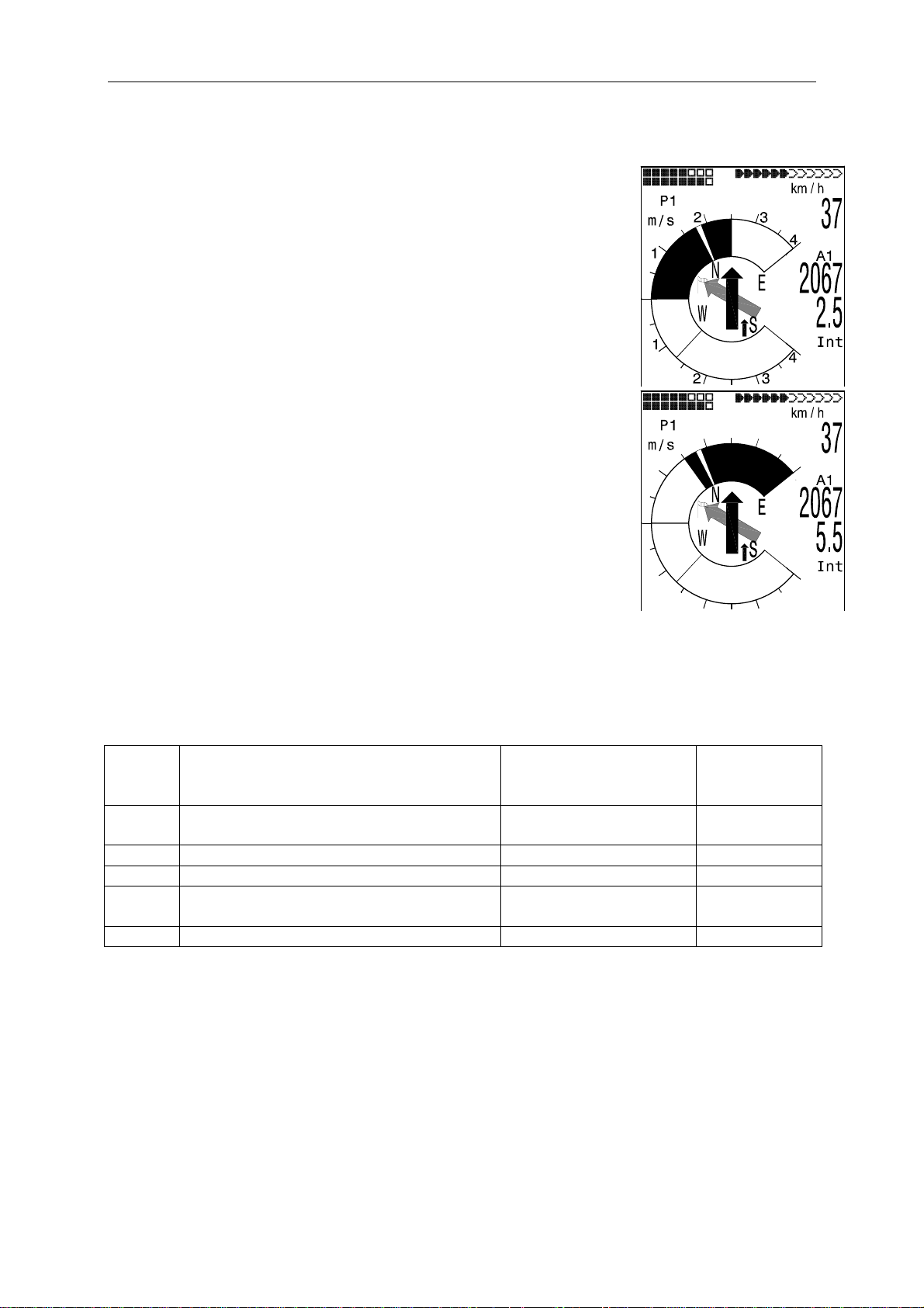
2.6.5 Flying Routes
A route is an arrangement of various waypoints. The
waypoints used on a Route need to be saved in the unit’s
memory. Whilst in the Goto-Function the next WP has
to be selected each time from a list by prolonged pressing
of the
forward by briefly pressing the key ▲ (next WP) or ▼
(previous WP ) if one is inside the WP Menu. The WP
Menu is enabled by prolonged pressing of the
It is only possible to select Routes which contain at least
one waypoint. Selection of a Route is effected by
prolonged pressing of the
Each Route should also be assigned a name,
for ex. „ Cassons Grat“.
In the centre of the compass rose a thick black arrow
points to the direction of the next waypoint. The
direction to the next but one waypoint is illustrated
in shaded mode.
2.6.5.1 Routes: Set – Delete – Alter – Copy
Main Setup Menu
Routes. (Max. 20 Routes). From this list any one of these
Routes can be selected by using the ▼ or ▲ keys.
Routes may also be set comfortably on the PC by use of the
PC-Software „Flychart 4.52“ and be transferred via the PCinterface to the instrument.
To delete select the key
key
Route can be created.
Setting a new Route
After pressing the key
entered for the Route. The cursor will blink on the first letter of
the word “Xxxxx”. By using the ▲ or ▼ arrow keys one alters
each to the desired letter. By using the ► key one proceeds to the second letter, enters the
changed letter, and so forth.
By pressing the
key, when flying Routes it is possible to switch
McC
key.
key.
⇒
Routes gives access to the list of saved
F2
OK
. However, by pressing the key F1 (Ins. Route), a new
OK
key one concludes the entry of the Route name.
(Del.-Route), or to alter select the
F1
(lns.Route), at first a name has to be
Routes
=================
Flytec
Fiesch
Flims, Station
Cassons Grat
Stanserhrn-Arvi
Engelberg
================⇓
Route 2
Fiesch
Total Dist: 16
No of Waypoints:2
----------------
Ins Del
Rte Rte
- 23 -

Operating Manual Flytec 6020
Now at this point the individual waypoints need to be inserted into the Route.
After pressing the key
half of the screen in alphabetical order. At the same time one will see the prompt: “Select
Waypoint No1.” Again by using the ▲ or ▼ keys one has to search for the 1
added to the Route by pressing the
By pressing the key
the Route with the
F1
(lns.Wayp), the list of available waypoints will appear in the bottom
st
OK
F1
(Ins.WP) again, one can select the second waypoint and add it to
OK
key etc. The highlighted waypoint (now offset in black) in the Route is
key. This is indicated in the upper half of the screen.
WP and it is
always the last one entered, which means that the function “lns.WP” will set the next WP to
be entered after the one highlighted in black. If e.g. one wants to insert an additional
waypoint after WP1, then you highlight WP1, press the
F1
key (lns.WP); then the prompt
“Select Waypoint No 2” appears.
If you notice, for example, that Waypoint No. 4 must be changed, then you select and delete
it and insert a new one after the existing WP3 by pressing the
available waypoints appears and the request “Edit Waypoint No 4”. After selecting and
pressing the
OK
key, the old waypoint is replaced by the newly chosen one.
F1
key. Again the list of
If one wants to delete a waypoint from the Route, it is marked and completed by pressing the
F2
key
(Del. Wayp). The waypoint is then deleted from the list without any additional query.
Altering a Route
You select a route to be changed with the ▲ or ▼ keys and confirm with
name is changed first. If this is not what you want, then it is sufficient to press
OK
. The Route
OK
again in
order to get access to the waypoints of the Route. As described in the last paragraph,
additional waypoints can now be added or deleted.
Deleting a Route
You select the route to be deleted with the ▲ or ▼ keys and confirm by pressing the key
F2
(Del.Route). For data safety the 6020-GPS inquires once again: (“Delete Route?”)
which is to be answered with Yes or No.
Copying a normal Route as Competition-Route
Each one of the existing Routes may be copied into the memory of Competition-Routes.
For this purpose the required Route is to be marked and followed by long pressing of the
McC
key. Please note that after this entry the start cylinder, radii and start time need to
be set separately, because all cylinder radii are reset to the default value of 400 m.
2.6.6 The Competition-Route
In contrast to the routes described above, the Competition-Route contains waypoints which
are mandatory to be reached; for example turning points in competition or FAI-record
flights, or performance flights. The regulation, which only recently came into effect in
documenting distances flown, fully relies on the recording of GPS-Receiver position data
(Tracklog points).
It is only when flying Competition Routes that the pilot will be warned by an acoustic
alarm when approaching his waypoints or when leaving the start cylinder and that the
unit switches automatically to the next waypoint. Call-up of the Competition Route is
effected by prolonged pressing of the
key and confirmation by OK key. The CompetitionRoute, once it has been activated, remains enabled even after switching-off the instrument.
It can only be disabled by prolonged pressing of the
key followed by F2 Cancel Route.
Instead of the previous photographic sectors the pilot only needs to reach a predetermined
distance to the turning point. It is also called the entering flight into the cylinder.
- 24 -

Operating Manual Flytec 6020
This distance, or cylinder circumference can be set in
Main Setup Menu
⇒
Routes ⇒ COMPETITION-ROUT for
each waypoint separately within the range of 20 m up to
max. 200 km. In Default- or factory settings a cylinder
circumference of 400 m is pre-set.
Setting of the differing cylinder radii, of start time, the flight
task (=Entering or Exiting the start cylinder) is effected
upon data entry of the Competition-Route.
Beside the automatic shift to the next WP, the pilot can
also shift manually by use of arrow keys ▲ or ▼ to the
next or to the previous WP.
2.6.6.1 Flying Competition-Routes
Because the GPS-Receiver of the 6020-GPS identifies its new position every second,
it takes only this one second to inform the pilot about his crossing of the turning point
cylinder circumference or that the time has come to leave the start cylinder.
In this case a long, unmistakable tone sounds during 2 seconds (CMP-Sound) and the
instrument switches automatically to the next waypoint of the Route. Independent of what
recording interval for storage is used during a standard flight, it is anyway guaranteed that
several Tracklog points are saved in the memory of the 6020-GPS at one second intervals
when crossing the cylinder circumference.
Usually the start cylinder is in first position of the Competition-Route. (However this is not
mandatory). If during setting or changing the Competition-Route after marking a waypoint
the key
McC
is pressed, the letter “S” for Start-Cylinder appears behind the WAYPOINT
name. The “S” disappears if the same key is pressed again. Only if a waypoint is marked
with “S”, it is necessary to set also a Start time and as task ENTER or EXIT.
If no WAYPOINT has been designated as Start-Cylinder, the pilots are not bound
to observe a start time and the automatic shifting to the next WAYPOINT is effected,
as soon as the pilot is present inside the cylinder.
If however in a competition a start cylinder is predetermined, the valuation starts as soon as
the start time is reached under these conditions:
Startmode EXIT: if the pilot leaves the cylinder from inside to outside.
Startmode ENTER: if the pilot crosses the Start cylinder from outside to inside.
It is possible to choose several start gates.
COMPETITION-ROUTE
=================
Flytec 0.4S
Fiesch 0.4
Flims, Station 0.4
Cassons Grat 0.4
Stanserhrn-Arv 0.4
Engelberg 0.4
================⇓
Wp1/6 in Route
Flytec
Total Dist: 16
Radius[m]: 2
Start14:15+05min
Gates 02 EXIT
- 25 -

Operating Manual Flytec 6020
EXIT Cylinder
WP2
WP3
WP1
Exit
The signal „waypoint reached“ is audible as soon as the start time is reached and the
pilot is inside the start cylinder. It will also sound if the start time is positive and the pilot
crosses the start cylinder circumference from outside to inside. In both cases the next active
waypoint will be enabled, in this case Waypoint2. All calculations and the direction arrows
are now pointing to Waypoint2
If the pilot decides to take the next start gate, he must press the Prev WP ▼ key.
(Select with key
McC
the Sub-Menu Prev/Next WP). The instrument then enables WP1 again
and will increment the start time by the preset difference. When the last start gate is reached,
the start time will no longer be increased after pressing of Prev. WP ▼.
Caution: for EXIT cylinder it is required that the first waypoint after the start cylinder is
outside of the start cylinder!
ENTER Cylinder
WP3
WP2
WP1
ENTER
The signal „waypoint reached“ is audible as soon as the start time is positive and the
pilot is crossing the start cylinder circumference from outside to inside. In this case the
next active waypoint will be enabled, in this case WP2. All calculations and the direction
arrows are now pointing to WP2
If the pilot decides to take the next start gate, he may press the Prev WP ▼ key.
(Select with key
McC
the Sub-Menu Prev/Next WP). He can do this regardless if he is present
inside or outside of the cylinder. The instrument then enables WP1 again and will increment
the start time by the preset difference. When the last start gate is reached, the start time will
no longer be increased after pressing of Prev. WP ▼.
Caution: for ENTER cylinder it is required that the first waypoint after the start cylinder is
inside and usually in the centre of the start cylinder!
- 26 -

Operating Manual Flytec 6020
During a flight the pilot can see on the Info-field display via count-down how many seconds /
minutes are left before opening of the Start line. At the same time he can read in the
display „Dist to WP“ and “Dist.Cyl” if he is inside or outside of the start cylinder.
If the pilot has flown out of the WP-Cylinder and the instrument has shifted to the next
waypoint, it is possible by pressing the ▼ arrow key to switch back at discretion to the
previous waypoint, and by pressing the ▲ arrow key to shift again to the next waypoint.
This is useful when a pilot, after having left the start cylinder, has decided to fly back and
to restart at a later time.
Also during the flight in Competition-Route, it is possible by using the Goto-key (prolonged
pressing) to call-up additional waypoints (thermal sources), sorted according to their
distance from the pilot. The waypoints being part of the Competition-Route are marked with
an asterisk in the displayed list; this means it is mandatory that they need to be approached.
Even in case a waypoint not belonging to the Route has been called-up, the alarm remains
enabled when entering the cylinder of the waypoint belonging to the Route. With the
it is possible to toggle back and forth between the waypoint of the Competition-Route and the
other waypoint.
After completing a flight task, the waypoints belonging to the Competition-Route will be listed
in the data transfer to a PC under the header of the IGC file. A n appropriate PC program can
check therefore if the assigned task was completed correctly.
When setting up a Competition-Route without a start cylinder, i.e. without a start time, the
automatic switch over to the next waypoint is effected, as soon as the pilot is present inside
the 1. cylinder radius. So it makes no sense to choose the “Take off” place as the 1
waypoint, because immediately after receiving satellites the instrument switches over to the
next waypoint.
2.6.6.2 Competition-Route Set – Alter – Delete
Even so a called-up Competition Route is treated differently than
a usual Route during flight and also for data transfer after the
flight’s completion, there is no difference when setting or
changing it. The route can be set up with the help of the keypad
of the instrument or can be transferred from the PC. This
feature is particularly useful for Competitions when in a short
time the flight tasks on the basis of turning points have to be
distributed error free to many pilots. The waypoints of the
Competition-Route can be altered, however the designation
„COMPETITION Route“ can not be deleted. If the CompetitionRoute does not contain any waypoints, it cannot be selected.
Each one of the other existing Routes can be copied to replace
the Competition Route. (In Main Setup Menu
selected Route press the
McC
key). This same key is also used to
⇒
Routes ⇒
assign to one waypoint the status of start cylinder.
After pressing the
OK
key, the start mode (ENTER or EXIT), the cylinder radii and the start
COMPETITION-ROUTE
=================
Flytec 0.4S
Fiesch 0.4
Flims, Station 0.4
Cassons Grat 0.4
Stanserhrn-Arv 0.4
Engelberg 0.4
================⇓
Wp1/6 in Route
Flytec
Total Dist: 16
Radius[m]: 2
Start14:15+05min
Gates 02 EXIT
time are to be set. It is possible to use the same waypoint several times consecutively
with different radii (e.g. the arrival cylinder and the landing place)
2.6.6.3 Distance to Waypoint cylinder
In order to ease the decision if having to peel off, the user field “Dist.Cyl” displays the
distance to the radius of the actual waypoint cylinder. This is particularly helpful for start
cylinders, as one has not always memorised at which size the start cylinder was entered.
F2
key
st
- 27 -

Operating Manual Flytec 6020
2.6.6.4 Dist to Goal (Total distance to the Goal of a Route)
In this field there is displayed during flight of a Route the sum of the legs lying in front of the
pilot. The distance is calculated from the current position. Thus he knows at any moment,
how much km are still in front of him until completion of the task
2.6.6.5 Distance to starting point
The instrument memorises the coordinates of the point, where the start recognition
(flight acceptance) has begun. This is a GND Speed of 10km/h for more than 60 seconds.
With user field “Dist.Start” the distance to this point can be illustrated. Usually this is the
point from where one has started.
2.6.7 Diff. BGGoal
Furthermore it is possible to pre-calculate the expected arrival altitude above goal over
several waypoints for display in the user defined field „Diff.BGGoal“. This computing
incorporates wind strength and direction, which one has determined by flying a full circle.
Hereby it is assumed that one is flying from the actual position in direct flight to the next
waypoint, and continues from there on the Route. The calculation is assuming that one
is covering the leg with the speed of best glide. On this note it is simply an estimation,
allowing the pilot to determine his strategy under consideration of local topography and
of wind components. The display shows the pilot if he has sufficient height to fly over
the last waypoint directly to the goal. See also chapter 2.7.4 (= L/D ratio) page
WP1
WP2
Goal
Start
32.
- 28 -

Operating Manual Flytec 6020
2.6.8 Relocating Thermals
With weak or widely dispersed thermals this function
helps to relocate any lost thermals. A small arrow
pointing up in the compass rose shows the direction
to the last thermal with at least a 1 m/s climb. If this
arrow is positioned at the top of the display, then you
are flying towards the thermal, however, if it is
positioned in the lower part of the display, you are
flying away from the thermal.
In case one wants to use this function, then the
indicator "Dist Therm" should additionally be
activated in the user defined fields. This value
indicates the distance from the pilot to the last
Thermal.
The threshold level to which the arrow should be pointed can be set under
Main Setup Menu
Therefore the arrow is not pointed directly to the centre of the thermal, but to its periphery,
as one obviously should relocate the entry area.
2.6.9 XT Error, Crosstrack Error
This field indicates the shortest distance (perpendicular to the Track and related to a map
view) to the active leg of a Route.
The accuracy of the indicated value depends on the length of the active leg. The largest
Inaccuracy arises in the centre between start and the next waypoint, if one is very close to
the track (the angles become very flat). With 50 km distance between start and waypoint, the
inaccuracy in the centre can reach up to 400m. Positive values are displayed if one is
on the right of the track, negative values on the left of the track. Even if one has cross flown
over the next waypoint, the distance to the straight line is shown. (see position 3).
2.6.10 Air Space - CTR (Restricted areas)
On the 6020-GPS up to 150 CTR’s can be entered. The CTR’s may comprise straight lines
and arc segments, or also be circles. These sectors appear in the Map Mode.
Each CTR may be composed of max. 110 waypoints.
⇒
User Settings ⇒ Variometer ⇒ Thermal threshold from 0.5 up to 3m/s.
Pos 3
Waypoint
Negative
value
Positive
value
Start Goal
- 29 -

Operating Manual Flytec 6020
p
CTR’s can be entered into the instrument either manually in Main Setup Menu
⇒
Airspace,
or with less effort by assistance of a PC-program, e.g. Flychart, this program may be
downloaded from our Internet Homepage at (
www.flytec.ch).
• Without activation the user has 20 CTR’s at his disposal. One can in Basic Settings ->
Init CTR’s call-up the CTR Innsbruck into the instrument and then alter it in
Main Setup Menu -> restricted areas.
• With activation code there may be used up to 150 CTR’s, depending on how complex
they are. It is necessary to activate the SW Package 02 for this purpose.
Name of CTR
ersonal comment
Restricted areas
=================
CTR1 Alpnach
TMA 1 Alpnach
TMA 2 Alpnach
================⇓
Ctr1
CTR 1 Alpnach
Höhe FL130
No Elements:8
Ins Del
Ctr Ctr
Information to
number of
endpoints /
elements
The CTR is defined by endpoints and arc segments or just by a circle. When entering these
elements it must be taken care of that the endpoints are precisely created in their order of
appearance (to the right or to the left) in which these lines should be displayed later.
The 6020-GPS instrument draws automatically a line from the recent waypoint to the first one.
It is therefore not required to repeat as last waypoint the first one.
As type the following elements can be selected:
Point: endpoint
Centre: centre of arc segment
Startboarder: Startpoint of arc segment
Stopboarder: endpoint of arc segment
Circle: centre of the circle plus Radius
example
counter-clockwise
7. Point
6. Point
1. Point
2. Point
5 Stopboarder
Dir -
3 Center
4 Startboarder
Dir -
1. Point
2. Point
6. Point
CTR1 Alpnach
=================
Point 1/7
Point 2/7
Center 3/7
Startb. 4/7
Stopb. 5/7
Point 6/7
================⇓
Point
Lat N 47’00.783
Lon E008’17.917
Ins Del
Ele Ele
- 30 -

Operating Manual Flytec 6020
To enter arc segments, then the following sequence must be observed:
Long, Lat centre;
Long, Lat start point of arc segment;
Long, Lat endpoint of arc segment;
Rotational direction (+clockwise, - counter-clockwise)
For circles the centre and the Radius are sufficient
Long, Lat of centre;
Radius in km.
2.7 Flight optimisation
2.7.1 Groundspeed (Speed over ground)
The GPS-Receiver calculates its new position once every second. Speed over Ground is
derived from the distance between these positions. From the difference between Airspeed
and Speed over Ground it is possible to reach conclusions about the wind’s influence.
2.7.2 Head- Cross or Tailwind; the Wind component
During a flight to goal or in calculating a final glide, it is not really the absolute value of wind,
but the wind component, i.e. the difference between Ground speed and Air speed, that is
decisive. In most cases the wind does not blow directly from the front or from behind, but
somewhat from the side. If this wind component “Spd-Diff” (in the user defined fields) is
positive, then the pilot will fly with a tail wind and the glide ratio over the ground will improve.
If it is negative, it contains at least a part of head wind and the glide ratio over ground will
decrease. The 6020-GPS takes this wind portion in any case into consideration for
calculation of the final glide. The Windspeed can be displayed as user field.
If the windsock indicating the wind direction covers the wind symbols N E S W, then for
reasons of clarity the corresponding letter positioned below shall disappear!
2.7.3 Wind direction and Wind speed
It is very important to know the wind in direction and
strength, especially in case of an out landing. The Wind
strength can be selected In the user defined fields.
However, for this purpose it is necessary to fly one or two
complete circles as steadily as possible. Whilst circling,
the 6020-GPS determines the direction of least speed
over ground and checks also synchronously if in opposite
direction there might be the fastest speed over ground.
.
Therefrom it is possible to compute the values for wind direction and wind speed.
Wind direction is shown in the compass rose at the position from where the wind is blowing
by a small windsock symbol.
During the landing approach this symbol should always be at the top.
- 31 -

Operating Manual Flytec 6020
2.7.4 Glide ratio ( = L/D ratio) By definition, the glide ratio is calculated by taking the horizontal distance traveled and
dividing it by the height which was lost. If instead of the horizontal speed is taken the
speed through the air, the error is 2% at glide ratio 5 and just only 0,5% at glide ratio 10.
This small inaccuracy is insignificant and may be disregarded
Within the user defined display fields the glide ratio may also be selected.
Hereby the following facts are applicable:
Glide ratio through the air:
L/DAir
= TAS/Sink True Air Speed divided by Sink rate
Glide ratio over Ground :
L/D Ground
= GS/Sink Speed over Ground divided by Sink rate
Required Glide ratio over Ground from momentary position for reaching selected WP:
L/D Req = Distance to the WP / Height difference to WP
Required Glide ratio over Ground from momentary position for reaching the goal.
example for explanation of glide ratio (L/D) values:
Best glide –
exit point 931m
over the goal
act. height
956m
681m
Alt a BG
275m
Best glide 8
L/D req 5.7
2km
Act. distance to WP 5.45 km
This field indicates the required glide ratio over ground to the goal crossing several waypoints.
This user field is only displayed if a Route is active. This way it can be decided, whether
one
should be flying directly to goal while crossing several waypoints, or whether one must gain
height in between within a Thermal. The calculation does not take into account if there is
a waypoint in between with higher altitude than the direct line from current altitude position
to the goal.
2.7.5 Safety altitude over the path of best Glide – Diff.BGWayp and Diff.BGGoal
In order to evaluate if one has sufficient safety altitude, these two user fields display the
difference between current altitude and the altitude which is necessary to reach the goal with
the speed of best glide. The best glide includes the momentary flight conditions.
Up-wash and down-wash, as well as head- or tail wind are also taken into account. However,
this calculation does not consider that on the path to the active waypoint other climb- or sink
zones can be incorporated, or that the wind values accounted for in the computing can be
- 32 -

Operating Manual Flytec 6020
subject to modification. Furthermore the glide ratio for best glide as entered into the instrument
settings must be correct.
If the Diff.BGWayp is positive, it represents a safety altitude which the pilot may loose accessorily
for reaching the active WP even so while flying with the speed of best glide. If this altitude is
negative, the pilot needs to circle up to at least the indicated altitude for reaching the goal.
Diff.BGGoal calculates this altitude over several waypoints of a Route to the goal, starting from
the current position.
2.7.6 Display screen final approach
In order to realise all these data at a glance, the Flytec 6020-GPS
provides a specific display screen which shows the pilot in an
intuitive mode, if he can reach his goal and in which way he can
reach it optimally.
After repeated pressing of the
approach appears as in the illustration on the right, for graphic
presentation of the calculation for final approach. Cross hairs
show the path to goal, a glider symbol in relation to it, and the
pilot’s position.
The horizontal scale of the cross hairs shows the deviation
between current track and goal (e.g. caused by shearing winds).
Each graduation line corresponds to 10°. In the illustration the
pilot is drifting by 22° too far to the right.
The vertical scale shows the glide ratio. In the intersection of
cross hairs is positioned the best glide ratio of the wing as entered
into the Basic Settings. When wind is encountered, this glide ratio
shall be rectified by the corresponding wind component.
Each graduation line corresponds to 0,5 glide ratio.
WP1
Start
WP2
Page/ESC
On/Off
key the display screen for final
Goal
- 33 -

Operating Manual Flytec 6020
Best glide –exit
point 931m over
the goal
act. height
956m
2km
For the example given above the pilot has entered the best glide ratio 8. If he would be
precisely on the path of best glide, the wing symbol would be exactly on the horizontal line,
and „Alt a.BG“ should be 0. Because his distance to goal is still 5,45 km, his altitude
should be in this case by 5450 : 8 = 681 meters higher than goal. However, „Alt a.BG“
indicates 275 m, therefore he is by 681 + 275 m higher than goal. The required L/D is
indeed 5450 : 956 = 5.7. The paraglider symbol is therefore 8-5.7= 2.3 Units or 4.6
crosshairs above the best glide line .
The strategy during the final approach is to hold the symbol in the cross-point. In order
to have some margin, experienced pilots will rather hold the symbol somewhat above the
cross-point of best glide.
During thermalling, the symbol remains on the vertical axis. As long as the deviation is more
than approx. 20 L/D, the symbol appears in grey in the centre. Below of approx. L/D 20
the symbol disappears. Upon approx. L/D 6 it reappears again on the screen bottom-up.
When it goes upside over the upper margin, it will again appear in grey.
Also during thermalling there is a small arrow ^ as exit assistance in the upper part,
if Track and Bearing correspond to each other within +/- 10°. When sinking the
arrows <^> show a recommendation in which direction one should head for.
If the symbol leaves the range of approx. plus minus 60°, it shall be presented in grey.
In this case one should shift back to the Vario screen using the
the compass rose with its direction pointers.
681m
Alt a BG
275m
Best glide 8
Act. distance to goal 5.45 km
L/D req 5.7
Page/ESC
On/Off
key, in order to see
- 34 -

Operating Manual Flytec 6020
2.8 Battery - Management
Two Bargraph scales show the charge state of the batteries. The Flytec 6020 is provided
with 2 battery banks with 2 batteries each. Bank 1 must always be loaded. Bank 2 may be
kept unloaded. However, it is highly recommended to also equip Bank 2. As soon as Bank 1
batteries are discharged, the instrument automatically switches to Bank 2. We recommend
to place the partly discharged batteries of Bank 2 after a long flight into Bank 1 and to place
new batteries into Bank 2. In doing this it is ensured that you may use up the batteries
completely without taking the risk that during a flight all the batteries are discharged.
The following batteries are appropriate for use:
• 2 pieces each per Bank Alkaline High Power batteries 1.5V size AA.
Estimated operation time - 2 times 20h = 40h in total
• 2 pieces each per Bank NiMH accumulators 2100mAh or more, 1.2V size AA.
Estimated operation time - 2 times 15h = 30h in total.
The correct battery type needs to be set in Main Setup Menu
If a wrong setting has been entered, it may induce to the result that the instrument
prematurely switches off completely, when changing from Bank 1 to Bank 2.
We recommend not to use NiCd accumulators. These batteries have significantly reduced
capacity and they are less environment-friendly. Also the switching threshold data are not
laid-out for NiCd Accumulators.
The estimated operation time mentioned above is based on normal temperatures (20-25 °C).
At low temperature the batteries and accumulators have a considerably shorter service life.
Bank 1
Bank 2
⇒
Instr.Settings ⇒Batterytype.
- 35 -

Operating Manual Flytec 6020
3 The Setting Menus
Prolonged pressing of the OK key gives access to the setting mode. With the arrow
keys▼ and ▲ one of the menu items is selected and pressing the
OK
key gives access to
the relevant subdirectory.
3.1 User Settings
A series of settings allow the instrument to be programmed in accordance to the user’s
preferences. Every pilot may realise his very own ideas here. All the basic settings can be
set comfortably on the PC by use of the PC-Software „Flychart“ and be transferred later
to the instrument via the PC interface. Manufacturer’s approved basic settings are called-up
with Main Setup Menu
settings. Please note to use this setting in case of emergency only, because hereby all
waypoints and Routes shall be erased. In most cases the possible setting range and its
previously valid value is indicated individually for each of the settings. If this value should
be modified, pressing the
will blink and can now be changed by use of the ▼ and ▲ arrow keys. Pressing the
confirms the new value, pressing the
Term Denotation more Factory setting
Variometer
Ground filter Diagnose of time constant f. Vario
Digital Vario Integrator Shift Integr.- Netto-Vario; Integr.Thermal threshold Threshold for the last climb 29
Variometer Acoustics
Acoustics settings Climb tone frequency, modulation;
Climb acoustics
activation threshold
Sink tone activation
threshold*
Speed
Sensor setting
Wind vane
Stall Speed Activation of Stall alarm and altitude
Flight Memory
Recording Auto/Man Automatic or manual Flight recording 38 Aut.
Recording interval Time interval per recording point -
Polar curves
Pilot name
Glider type
Glider ID
⇒
Memory ⇒ Memory format, and they are saved again in the
OK
key gives access to change mode, the value to be modified
Page/ESC
On/Off
key recalls the previous setting.
info
14
12 ( ≈ 1,2 sec)
OK
key
and Speed
14 Integr. 1 30 sec
time constant
1 sec
15 1200 Hz; Mod =
Sink tone frequency.
Acoustics dampening; Pitch
Fine tuning of climb tone threshold,
15 2 cm/sec
5,
700 Hz, 8, Pi = 3
max 20 cm
Activation point of Sink tone 15 0,8 m/s (ft/m)
Correction Wind vane 70 ... 150 % 17 100 %
15 0 km/h (mph)
limit
38 10 Sec
2 to 30 seconds
Glide ratio at speed of best glide
Entry of pilot’s name; max 25 char.
Name of aircraft for OLC
Ident.No. of aircraft for OLC
28 L/D 8 to 40km/h
10 not set
10 not set
10 not set
- 36 -

Operating Manual Flytec 6020
3.2 Memory Management
Delete all Flights
Delete all WP’s &
Routes
Formatting Memory
Delete all Air Space
CTR data
Caution: When deleting WPs, Routes or flights, the deletion process takes a couple of
seconds, please wait during this time span.
Deleting the entire flight memory. This
command reformats the flight memory,
while all the other settings are not lost.
Deleting all WP’s and Routes
Reset of Basic values to factory settings
Reorganisation of the Memory zone for the
Restricted Areas (CTR’s)
38 No
21 No
38 No
29 No
3.3 Instrument Settings
Term Denotation more Factory setting
Display contrast Range 0 .. 100 % 70 %
Language Selection is possible from 5 different
languages
Battery type Battery type. Selection possible between
Alkaline or NiMH accumulators
Time zone Difference to UTC; 0.5h time zones can also
be set
Units Meter or feet; Km/h or mph or knots.
Temp. in °C or °F
Coordinate format dd'mm.mmm or dd.ddddd or dd'mm"ss UTM
or Swiss-Grid
Pressure sensor Corr This setting allows correction of a possible
deterioration of the pressure sensor.
For checkup the QNH-value is used.
If you know the QNH-value of a certain
location (e.g. airfield altitude), the
altitude needs to be consistent with the
effective altitude. 1hPa corresponds at
500m to approx. 8m.
Bluetooth Only active when SW Package Bluetooth is
activated. Here is made the Pairing of the
Bluetooth interface for the SMS function.
SMS Only active, when Bluetooth and SMS
SW Package is activated. Here is entered
the target telephone number and the Mode.
Opt. Software Here are activated additional SW functions
(Packages). For this purpose the relevant
manufacturer’s Code is required.
Factory Settings Disabled Zone
info
English
Alkaline
-2
m ; km/h ; °C
dd'mm.mmm
0 hPa
- 37 -

Operating Manual Flytec 6020
3.4 Specific Instrument factory settings
This default value, which is not accessible to the pilot, contains all basic settings of the
instrument. In particular, both the sensor specific parameters and all calibration data are
located here. These data are not lost, even when the power supply is missing.
4 Flight Memory and data analysis
The flights are recorded inside a Flash-Memory (see below). Each trackpoint contains time of
day, position, GPS-altitude, barometric altitude as well as speed through the air. Due to this
feature it is possible later on to reproduce the barograph and individually the graph for Vario,
Speed, and the track (course) of the flight over a map presentation. These data are processed
for flight analysis by various analysis programs. With Flychart 4.52 it is for example possible
to retrace the flight on the PC-monitor in three-dimensional mode over the corresponding
territory. (Google Earth).
The Flytec 6020-GPS provides in total 3 memory zones.
Content Type Access with Delete
Program Memory Flash Flasher tool at switched-off
instrument
Flight Memory Flash
Waypoints, Routes
and Air Space
User and
Instrument Settings
Serial number,
Adjustment data
EEPROM
EEPROM
EEPROM
Main Setup Menu ⇒
Flightmemory
readout of flights over the
USB interface
Main Setup Menu ⇒
Waypoints or
⇒
Airspace
Main Setup Menu ⇒ User
Settings or
Main Setup Menu ⇒ Instr.
Settings
Password protected
⇒
Routes or
⇒
Instr.Settings
⇒
Factory settings
The Flasher tool overwrites the
memory each time
Main Setup Menu ⇒
Memory
Main Setup Menu
Memory
⇒
Main Setup Menu
Memory
Not possible
⇒
Delete flights
⇒
Delete Wp&Rt or
Delete Airspace
⇒
Format. memory
⇒
⇒
4.1 Flight-Memory and Flight-Analysis
The recording mode does not need to be specifically
activated, as each flight is automatically saved.
The flight memory used in the 6020-GPS not only records
flight altitude and flight speed TAS, but it also logs the
position of the pilot and the GPS altitude in the WGS84
co-ordinate system.
In Main Setup Menu
⇒
Recording Interval the recording interval can be set. The
set value determines the time interval counted in seconds,
after which a new data record is entered into the memory of
the 6020-GPS. The minimum value is 2 seconds, which is in
accordance to a recording time of approx. 9 hours.
At maximum value of 60s, the total recording time is
approx. 291 hours.
⇒
User Settings ⇒Flightmemory
Main Setup Menu
=================
FFlluuggssppeeiicchheerr
WWeeggppuunnkktte
Routen
Lufträeume
>Benutzer Einst.
>Speicher
================↓
e
- 38 -

Operating Manual Flytec 6020
For tests or acrobatic flights a sampling rate of 2 seconds
is recommended. However, the recommendation as standard
setting is a recording interval between 5 and 10 s. With it
also narrow curves are well recognisable, and the number
of data points for the external computing of OLC points
remains manageable. Factory setting here is 10 seconds.
For the beginning of a flight the following arrangement applies:
the start is recognized as soon as the ground speed
reaches at least 10 km/h for more than 60 seconds, or if
altitude difference within 60s is more than 30m.
In each case however, the previous flight history with up to 30
recording points is filed in the 6020-GPS memory. With it, and
at 10 sec. recording interval, even the last 3 minutes before
the start of the filed flight can be noted.
An end of flight is recognized under automatic recording if there is no speed for 60
seconds (less than 10 km/h speed or airspeed) and also if no change in altitude occurs.
Then the standard display screen is automatically switched to flight analysis. From this
moment on the “digital signature” of this flight is calculated and a notice is displayed in the
info field. Please wait until this calculation is completed. With short pressing on the
one returns to normal mode.
It is also possible to shift the instrument to manual recording. For this purpose it is
necessary to select under Main Setup Menu
⇒
User Settings ⇒Flightmemory ⇒Rec.
Auto/Man the value “No”.
This setting enables the recording to start approx. 10 seconds after switch-on and
is only stopped after the
Page/ESC
On/Off
key has been pressed for 3 seconds.
The start of recording is visible by the running “Flight time” counter. Please take into account
that altitude A1 may not be changed during recording process.
Caution: Make sure before the start that the GPS-Receiver indicates to receive at least
4 Satellites in order to achieve valid recordings.
Comment 1: in the Flight analysis are displayed max. values which appeared during the flight.
Due to the fact that the display screen is updated every second, the 1-second values are saved
for the flight analysis. If one undertakes a download of such a flight afterwards on the PC using
a program such as Flychart, SeeYou, CompeGPS, MaxPunkte etc., these programs are only
appropriate to analyse the flight records in IGC format. In the IGC file are saved the time of day
(UTC), position, barometric altitude, GPS-altitude and True Air Speed of the wind vane or pitot
pressure sensor. The programs calculate the Vario-meter values out of the altitude data.
If for instance, one has set a recording interval of 10s, and has made a height difference
of 5m during these 10 seconds, the Vario value of 0.5 m/s shall be calculated. However,
during this time a 1-second Vario value of 2m/s may have been performed. Only this value
shall be indicated on the Flight-Analysis page and is not subject to electronic readout.
Comment 2: Although the instrument is capable to store up to 100 flights, we recommend
to save the flights in regular intervals on a PC and to reformat the flight memory afterwards
by entering the command Main Setup Menu
⇒
Memory⇒Delete Flights. This procedure
ensures the safety of data storage of your precious flights and that the instrument may
perform new recordings again with a „refreshed“ flight memory.
Flightmemory
================
24.09.04 1:09:04
2233..0099..0044 11::1188::2255
18.09.04 0:11:14
15.09.04 2:38:23
30.08.04 0:09:34
24.08.04 1:23:35
===============↓
Page/ESC
On/Off
key
- 39 -

Operating Manual Flytec 6020
4.1.1 Logbook and Flight Analysis page
After leaving the Flight-Analysis the flight is saved in the
flight memory. Data and Track of the flight can be viewed
on the Flight-Analysis page. Under Main Setup Menu
⇒
Flightmemory appears the list of saved flights in chronological
order. The recent flights rank first. The duration of the flight is
also displayed. With the keys ▼ or ▲ one scrolls through the
list, using the
displayed along with its basic values on the Flight-Analysis page.
By pressing the key
OK
key, the required flight is called-up and is
F2
Del. Flight it is possible to delete flights
individually from the list. If the entire flight memory should be
deleted, item Main Setup Menu
⇒
Memory⇒Delete flights
is to be selected.
4.1.2 Graphic Display of flights in Map format
The flight route of saved flights can also be shown
on the Display screen for appraisal. In Flight-Analysis
the key F1 is used for the function Show Map.
After pressing this key the screen-optimised illustration
of the flight route is shown (North is at the top!)
In addition, stored waypoints are presented with a cross
and the name, as well as the map scale as short line
with indication of km.
The graph can now be changed as follows:
F2: Zoom in: the map scale is gradually increased to
approx. 0,4 km. Thus individual circles during a climbing
period are clearly recognisable. (dependent on the
setting of recording interval).
F1: Zoom out: the map scale is gradually decreased,
0.9km
until the screen optimised graph is achieved.
The maximum is 47.4km
Arrow keys Pan: by use of these keys the illustrated
area can be shifted up, down, left or right.
(Function not enabled during an actual flight).
OK: from each graph back to the screen
optimized graph.
ESC: return to the Main Setup Menu
All the other keys cause the Track in the current selection to be redrawn.
Remark: as the illustration will take a few seconds to appear according to the data
volume, the message Wait and Ready appears on the status line as user information.
If a zoom or pan key is activated during the screen layout, the momentary process will be
discontinued and will resume with the new values. Hence one can obtain the desired graph
rapidly.
Remark: During the flight it is also possible to switch to a real time track and map graph by
briefly pressing the
Page/ESC
On/Off
key. Vario, altitude and speed appear digitally under the map. For a
Competition-Route also the cylinders around the WP’s are indicated.
During the flight the current end of track (= the momentary position of the pilot) is illustrated
by an arrow which is pointing in flight direction. The “Zoom out” zone has been extended (in
4 steps) so that in most cases a large part of the Route is displayed. The waypoints of the
Route are linked by fine lines for better clarity.
FLIGHT-ANALYSIS
Date: 24.09.04
Start: 06:19:06
Stop: 06:27:56
Fltime: 0:09:04
Scanrate: 10s
Max A1: 1153m
Max A2: 4273m
Max A3: 418m
M.Vario: 8.9m/s
M.Vario:-6.6m/s
M.Speed: 73 kh
WP1
BEAR
345
- 40 -

Operating Manual Flytec 6020
4.2 Data transfer
In the memory of the 6020-GPS are saved all data entered by the pilot, such as waypoints,
Routes, pilot’s name etc., as well as the automatically by the instrument recorded tracklogpoints of the flights being performed. Each one of these points contains the time of day,
position, GPS-altitude, barometric altitude, as well as the flight speed. In this way it is
possible to graph the Barogram, Variogram, Speedgram and the track (course) of the flight
over a map presentation for later analysis. With Flychart 4.52 it is even possible to retrace
the flight on the PC-monitor in three-dimensional mode over the corresponding territory.
For this purpose the software program Google Earth needs to be installed.
4.3 Data exchange via PC
The basic equipment of the 6020-GPS includes a data cable for a USB PC interface
USB Mini B. Due to this feature data transfer can be carried out in both directions.
The data transmission is effected via serial interface COMX with: 57.600 baud; 8 databit;
1 stopbit; no parity, Xon/Xoff.
Using the USB interface the 6020-GPS can also be operated for data readout and entry:
• entire instrument configuration (Basic Settings, User def. fields)
• list of waypoints
• list of Routes
Only readout of flights saved in the flight memory is possible.
Important: for transfer of a.m. data the 6020-GPS must first be switched-on and the relevant
program for data transfer has been called-up, before the connection cable to the PC is
plugged to the 6020-GPS.
Important: at first the USB driver as provided from Prolific has to be CD installed. Upon
installation of Flychart the USB driver installation is effected automatically.
To perform data transfer the instrument needs to be switched to the Main Setup Menu
by prolonged pressing on the
Please observe the instructions of the software being used for transfer of stored flight data.
(For most software programs it is required to shift to the Flightmemory resp. to the FlightAnalysis mode).
There are various software programs available for creation of IGC-files, partly even for OLC-files.
For more detailed information please check homepage
We recommend the use of Flychart which can be downloaded from the
website.
With Flychart all instrument settings can be effected comfortably on the PC.
Trackview (Freeware) Daniel Zuppinger (for OLC and CCC)
Maxpunkte (Freeware) Program by D.Münchmeyer for Online-Contest of DHV
Compe-GPS For competition and private pilots, 3-D presentation
Seeyou Flight planning- and Analysis software, www.seeyou.ws/
GPSDump Stein Sorensen . A simple program to receive IGC Files
OK
key.
http://www.onlinecontest.de/holc/
www.dm-sh.de
www.compegps.com
http://www.multinett.no/~stein.sorensen/
www.flytec.ch
www.softtoys.com/
- 41 -

Operating Manual Flytec 6020
g
4.3.1 Fightinstrument Option
All settings can be set or changed comfortably with Flychart 4.52
User settings
and Instrument
settin
s
4.3.2 Waypoints and Routes
Within the same Flychart Menu the Waypoints and Routes may be transferred to the
instrument. Flychart is also appropriate to import waypoint files from SeeYou or CompeGPS
or Garmin for transfer to the instrument.
4.3.3 Airspace (CTR)
The same principle applies on Airspace. For this purpose please activate button „Airspace“.
4.4 Transferring new software to the 6020-GPS
As is the case with many other present-day instruments, there is also the possibility to
up-date the software version (Firmware). Hereby future requirements presented by pilots
or new Competition regulations may be rapidly implemented. The manufacturer Flytec
shall post from time to time program up-dates of the 6020-GPS firmware on its Internet
homepage, which can be downloaded by the user free of charge for storage and
subsequent transfer to the 6020-GPS.
In order to be able to write into the 6020-GPS flash memory with a PC, the program
“Flasher.exe” is required, which is available in zipped format file under the name of
“Flasher.zip”. In addition, also the intrinsic firmware to be uploaded has to be obtained from
the homepage. Its name is e.g. “6020v325.moc” (approx. 500 KB) which is equivalent to
version 3.25.
We recommend to save all the related files in one single subdirectory (e.g. C:\Programs\
FlytecFlasher\).
- 42 -

Operating Manual Flytec 6020
After decompressing the ZIP file a number of files are created. Double clicking on the file
“Flasher.exe” starts the program.
One can set the interface, or in case it is not known, having it done by automatic search.
With "File" you select the program to be transferred with the extension " .moc " or you can
pull it from the Explorer into the field by drag & drop.
Boot the data transfer. The bootloader version of the instrument will appear and the transfer
rate. The numbers appearing in the field on the right side are the instrument’s response.
Important: By contrast to the flight data transfer make sure that the 6020-GPS is not
switched-on when the connection cable to the PC is plugged.
Caution: Never leave the PC cable hooked to the instrument for a longer period when
it is turned off. Indeed this is energy consuming and the batteries could be discharged
unnoticed.
Lead: In Windows the characteristic noise for USB devices should be audible when the unit
is plugged.
5 Miscellaneous
5.1 Optional Software (additional Software)
With the help of an activation code available from Flytec it will be possible to enable
additional special functions. For example by use of a 5-digit Code the diagram of Restricted
Areas (CTR’s) can be activated.
Procedure for Code entry:
• Select in Menu Optional SW Packages the corresponding package
• Press OK. Then a Code –29XXX will appear
• By use of the arrow-down key the Code jumps to 30000 and then counts downwards.
• Set the Code by use of the arrow-down key and press OK
• The instrument signals: Package released!
If a wrong Code has been entered, the instrument remains blocked for min. 5 minutes!
- 43 -

6 Simulation
Operating Manual Flytec 6020
After choosing the Simulation mode in the Setup Menu and pressing the
access to this highly interesting function. With the arrow keys and
Simulation checkbox to “Yes” and confirm again with
OK
. Now the simulation starts and the
OK
OK
key, you have
you shift the
last known GPS position is applied.
With the
► and ◄ arrow keys you can adjust the speed through the air and ground speed;
the ▲and ▼ arrow keys change the sink or the climb. If the stall alarm sounds, please
increase the airspeed by a few km/h.
The softkey F1 is used to change to various functions:
Next Func. Var ▲▼ Spd ►◄XX altering Climb/Sink Air + Ground-Speed
Next Func. Wind ▲▼ Trk ►◄ altering an assumed wind strength during climb and
altering of the Track (Flight direction) during sink
Next Func. Mod A1 ▲▼ altering altitude Alt1
Next Func. Mod A2 ▲▼ altering altitude Alt2
Next Func. S.Thr –▲▼ altering the starting point of sink acoustics
Next Func. Change page ►
Likewise, the Goto function can be called up to select a waypoint. The distance to this
waypoint appears. If the direction arrow in the middle of the compass points upwards, the
pilot is moving towards his goal and the distance becomes shorter while at the same time
also the altitude naturally decreases. If you now initiate a climb with the ▲ key, the
6020-GPS simulates circling up in a thermal; the compass rose turns and the distance to
goal continuously changes between somewhat closer and somewhat farther away.
Under simulation mode one can also test the different climb tone acoustic adjustments,
such as frequency, pitch and modulation during a virtual climbing.
Please shift back to dive. After pressing the
F1
key one can change by use of the ▲and▼
keys the Speed over Ground, i.e. simulate the wind influence. By using the ◄ and ► keys
it is also possible to change the flight direction, e.g. in order to fly directly to a WP.
One can also retrace perfectly in simulation a called-up Route. If you select the Route as
FAI-Route, you will hear the characteristic tone upon approaching the waypoint at about
400 meters, which signals that you are inside the cylinder, and you can see the automatic
switchover to the next WP too. (Caution: for automatic switch-over the count down timer
must show positive values).
By pressing the ESC key one can switch to map display and observe the approach to the
WP cylinder. If one has selected the function
Wind Track with the F1 key, it is real fine
to simulate the influence of head or tail wind during approach to the goal. It is indeed
informative to see the influence of head wind on the display of
Alt a BG.
During simulation mode the GPS-Receiver is switched-off and instead of its bar graph
the word "Simulation" appears.
A simulated flight is well stored into the memory of the 6020-GPS, but its “Digital Signature”
is not valid.
7 Disclaimer of Warranty:
In rare cases it might happen that the instrument does not provide any data at all or incorrect
data. The Company Flytec AG shall reject any claim on damage resulting from malfunction of
your instrument. It is solely the pilot who is fully responsible for the safe performance of his
flights.
- 44 -

Operating Manual Flytec 6020
7.1 Landing in Water
In case you are forced to land in water with your 6020-GPS and it may have penetrated the
instrument, there is still a chance to save the instrument or at least some of its parts.
Once water has intruded the GPS module it is then irrevocably lost. Take out all batteries
as fast as possible, thereby the circuit is disconnected from power supply. Then afterwards
the casing can be opened.
In presence of aggressive liquids, such as salt water, place the circuit board and all parts
affected by the salt water into warmed freshwater for a minimum of about ½ hour. Thereafter
dry the instrument carefully with warm air (hair dryer). It is also recommended to remove the
flat cable of the keypad.
Please return imperatively the dried instrument to Flytec Company for final check over.
Any claim under Warranty is void after a Water landing.
8 Technical Data
Dimensions: 178 x 95 x 40 mm
Weight: 425 Gram (without harness)
Power supply: 2 or 4 pieces Alkaline batteries AA, 1.5V
Battery operation time: > 20 hrs. per Bank, i.e >40h
Altimeter: max. 8000 m Scale 1m
Variometer: analogue ± 8 m/s Scale 0,2 m/s
digital ± 100 m/s Resolution 0,1 m/s
Speed wind vane digital 0 up to 120 km/h
Waypoints: 200 WP
Routes: 20 Routes with max. 30 WP each
Max. storage time: 48 hrs. Flight time at 10 s recording interval
max. 291 hrs. at 60 s recording interval
Restricted Areas 20 CTR’s free of charge, 150 CTR’s as charged service
Number of Tracklog points: 21 000
Number of recorded flights: 100
Data memory and transfer according to the IGC format
Screen resolution 38’400 Pixel / 240 x 160 Pixel ( = 1/8 VGA )
Operating temperature -15 C° ... 45 °C
Harness items for hang gliders and para gliders are available.
The technical data may be altered without prior notification at anytime. Software upgrades
can be made via Internet by downloading the latest firmware version from our homepage
onto the user PC.
- 45 -

Operating Manual Flytec 6020
9 Appendix
9.1 Altimeter
An altimeter is really a barograph because it doesn’t directly measure altitude, but air
pressure. Altitude is calculated from air pressure data. The pressure at sea level is used
as zero point altitude for the calculation of absolute altitude (according to the international
altitude formula).
Why does pressure change with altitude? Pressure at any given point on the earth is created
by the weight of air in the atmosphere above it. Therefore, pressure reduces with height –
there is less air above you. A change in pressure of 1 mbar at 500 metres local altitude
above sea level is a height difference of about 8m.
However, in practice, it is not as simple as that because more factors have influence on
air pressure. Therefore, air pressure is also depending on temperature and of course, on
weather conditions. On a stable day, temperature induced air pressure variations of 1mb
can occur, which means a height difference of ± 10 metres. Depending on the weather, air
pressure at sea level (QNH) may vary from 950 mb to 1050 mb. In order to eliminate the
influence of the weather, the altimeter has to be calibrated again at certain intervals. This
means the altimeter has to be set to a known height and it needs to display this height.
During rapid weather changes (e.g. passage of a cold front), the air pressure can change by
up to 5 mbar during one day. This means a height difference of 40 m!
Another alternative to calibrate an altimeter is setting it to the actual QNH.
What is QNH? General air traffic needs a common zero point. This means that at a certain
altitude all aircraft show the same altitude on the altimeter. This common reference basis
is the QNH. The QNH is the actual air pressure in hPa ( 1 hPa=1mbar ) calculated back to
sea level. It is calculated several times a day and can be taken from the weather forecast
for aviation or it may be requested by radio from airfields.
9.2 Speed
9.2.1 True or Indicated Airspeed - TAS or IAS
In general aviation it is customary to measure the airspeed by use of a pitot tube as a dynamic
pressure speed (=IAS) and also to display it as such. The advantage of this method is the fact
that at any altitude level the maximum admissible speed or the stall is marked (flight safety) at
the same position on the scale. Furthermore it is the same for the speed of best glide for any
altitude which is on a fixed position on the scale (flight performance).
It is however the disadvantage of this system that all geographic calculations, such as for
distance, required flight path angle, and all final approach computing, necessitate the true
air speed to perform the calculation.
Another disadvantage is the fact that the indicated speed is correct only at one certain
altitude (usually at sea level). The higher one climbs, the glider will fly increasingly faster due
to the air getting thinner, without the display screen following this fact. At approx. 6,500 m the
air weighs only half of that at sea level, therefore the air speed will increase by 1.41 times
(as a radix of 2).
- 46 -

Operating Manual Flytec 6020
The physics could be pictured as follows:
In order to create a certain lift a certain number of air particles need to hit the airfoil. Because
of the fact that at 6,500 m altitude there are now only half as many particles present per
meter, the wing surface has to fly faster, but not twice as fast, because each particle has a
higher striking energy and is then only 41% faster.
However, for the calculation of wind, arrival altitude or arrival time at goal, the true air speed
values are always required. The wind wheel sensor shows the true air speed (=TAS),
because it runs practically without friction.
The Flytec 6020 GPS indicates generally the true air speed - TAS.
9.2.2 Stall alarm
If a pilot slows down his glider gradually, he will cause a stall when falling below a certain
speed, which will have different consequences, depending on the type of aircraft.
If the air current is suddenly cut-off from the entire surface, then a completely unforeseeable
crash would be pre-assigned. For this reason, our airfoil manufacturers are building a
so-called cross-setting into the support parts of the wings; this means that during flight the
wing tips will always have a smaller stalling angle than the middle part of the glider. If the air
flow stalls in the middle part of the surface when falling below a minimum speed, then lift still
remains on the wing tips. The aircraft is now in the so-called descending or stall. Due to the
fact that the wing tips are positioned behind the aircraft’s centre of gravity, the aircraft will
independently drop nose downwards and try to increase the air current by gaining speed.
It is certainly to misadvise to remain a longer time span in this excessive flight situation, as
the wing will react extremely sensitive to even minor air turbulences. A stall can be
dangerous, especially during the landing approach. The consequence could result in a stall
over one surface or a non intended 180-degree curve. The stall alarm is a loud, concise
acoustic signal that requests the pilot to fly faster. It assists first and foremost hang gliders,
however para gliders to a lesser extent. Anyone who has ever watched a hang glider come in
during an approach can observe the following situation:
always when a good headwind prevails, many pilots will pull out their steering bar too early;
the glider then climbs a few more meters to end up in a favourable case afterwards with its
keel stuck in the ground. With no wind or with a light tail wind most pilots wait too long
to pull out the bar. In this case, and with any luck the result will only be a belly landing;
but also a ground-loop with broken base side tubes may be the result, or the glider’s nose
absorbs the impact energy when touching ground and the pilot will swing pendulum wise,
hitting his helmet on the front keel tube.
There are different stall speeds to apply for each glider and varying weight of the pilots.
Several tests are necessary to determine for the own arrangement the setting of correct
stall alarm limit in Main Setup Menu
it is worth to note that close to the ground, and because of the air cushion under the wings,
the stall occurs at approx. 2 km/h lower speed than in the high air.
However, stall speed also depends on the specific weight of the air, meaning: the flight
altitude. On the 6020-GPS the stall alarm level is automatically raised with increasing flight
altitude, corresponding precisely to Indicated Airspeed. It is unimportant if the pilot has
selected True- or Indicated Airspeed for the speed display screen.
The border limit between stall alarm and the speed for minimal sink is indeed very small.
Hence several pilots have complained about the fact that while circling up in weak thermals
at the speed of minimal sink, the stall alarm is triggered sometimes. In this regard there is
⇒
User Settings ⇒Speed⇒Stallspeed. Furthermore
- 47 -

Operating Manual Flytec 6020
an altitude limit to be adjusted by the pilot in Main Setup Menu
⇒
Stallspeed above which the stall alarm shall not be initiated. In this case naturally, the
landing areas should be located below this limit.
Practice has proven that about half of the otherwise unattractive landings have been rescued
by pushing the steering bar upright when the stall alarm was triggered.
⇒
User Settings ⇒Speed
9.3 Navigation
9.3.1 Reception quality of GPS
The GPS-Receiver can follow up to 16 satellites simultaneously. After turning on the unit it is
necessary to receive at least 4 satellites to fix position for the first time. Once logged on,
3 satellites (for 2D positioning) are sufficient for further position finding. However, if altitude
recording is also required (3D positioning), then definitely 4 satellites are required. There is a
table in the receiver, The Satellite Almanac, in which the path, place, and time of all
satellites are kept with reference to the receiver. The Almanac is continuously updated
during signal reception. However, if the signal to the Almanac memory is disrupted
completely or the unit is taken 200 km or more from the last reception point, then the
Almanac has to be re-established. Power is still supplied to the almanac’s memory even
when the unit is turned off.
Normally the instrument recognizes its position under unobstructed view condition after
a few minutes. If the receiver is switched-off for a short time (less than 2 hrs.), the time for
new position finding is less than a minute. Buildings, mountains or thick forest affect
reception quality of the receiver. Therefore, you should always look for the best possible
visibility around you and the antenna in the casing should point upwards if possible.
In particular when mounted on the steering bar of the hang glider, we recommend not to
have the instrument fixed under the pilot’s head on the middle of the basis, but indeed
sideways. In this position the 6020-GPS should not have more than 45° deviation from
horizontal position so that the antenna points upwards.
Due to the fact that receiving strength of the satellite signals is only approx. 1/1000 of mobile
radios, these radio sets and other disruptive factors (like notebooks) should be operated as
far away as possible from the 6020-GPS.
The 6020-GPS is fitted with a 16-channel GPS-Receiver which is featured with
lesser power consumption and also a significantly shorter satellite detection time.
Precision is between 7 to 40m. As an average one may assume approx. 15 m.
9.3.2 Accuracy of GPS altitude
A good explanation of GPS accuracy is found on the following website:
http://www.kowoma.de/en/gps/errors.htm
First of all the term accuracy has to be defined: On the website above you can read:
“The declaration of the accuracy by Garmin GPS receivers sometimes leads to confusion.
What does it mean if the receiver states an accuracy of 4 m? This readout refers to the
so-called 50 % CEP (Circular Error Probable). This means that 50 % of all measurements
may be expected within a radius of 4 m. On the other hand it also means that 50 % of all
measured positions are outside of this radius. If one assumes a standard dispersion, then
95 % of all measured positions are within a circle of twice this radius, thus 8m, and 98.9 %
are within a circle of 2.55 of the radius, thus in this case within 10 m. “
- 48 -

Operating Manual Flytec 6020
Satellite orbit radius
=26560km
Earth radius
=6360km
The position is derived from a triangulation. The GPS receiver measures the time of the
signals and calculates the distance to the respective satellite by taking into account the
speed of light. Based on three satellites the horizontal position can be determined, and
with 4 satellites the spatial position with altitude.
You can find a good explanation of the involved calculation on Wikipedia.
For a spatial position determination (3D position) there are needed 4 satellites,
one satellite is hereby required for synchronisation.
In case of a 3D position identification, best accuracy is achieved if the 3 satellites are 90°
to each other. In this case the volume of the spanned pyramid is the biggest.
Again the DOP (Dilution Of Position) is the inverse value to the volume of this pyramid.
For a good 2 D position on the earth surface it is best, if you have 2 satellites at 90° near
the horizon. So for example, one to the North, the other one to the East. The 3rd satellite
vertically above the position does not contribute to accuracy, it just gives a rough information
of the altitude, but which is good enough for a good lat/long determination.
90°
4th Satellite for time
Synchronisation
Best Accuracy is achieved if the angle
between 2 satellites is 90°. The
spanned triangle between one’s own
position and the two involved satellites
then has the largest possible surface
area. The unit DOP (Dilution Of
Position) is proportional to the inverse
value of this area
- 49 -

Operating Manual Flytec 6020
Almost no time difference
Satellite 2
The chance to find 2 satellites near the horizon being at 90° apart, is better than
to find 3 satellites with 90° to each other directly above the actual position.
Because the circumference area above the horizon is larger than the area perpendicular
above the position, and assuming that the satellites are nearly equally dispersed, there
is a bigger chance to find convenient satellites near the horizon. The GPS module will
therefore prefer satellites near the horizon. For determination of the horizontal position,
the module will calculate any combination of the visible satellites to make an average
of these combinations every second.
To do the same with the vertical position, the receiver would need twice the calculation
power. Due to the fact that motor vehicles and pedestrians normally require the horizontal
position, one saves the effort by computing altitude from the best combination and generates
the average by time. This is an explanation of the lower accuracy and the run after or delay
of the vertical position.
The GPS module of the Flytec instruments does not perform a timed filtering over the
horizontal position, but in case of good reception quality it does a filtering over approx. 5 s
for the vertical position. The poorer the GPS-reception, the longer this time constant.
Position A Position B
Calotte
Satellite 2
45°
Satellite 1
Time difference
Satellit 1
This circumference
area is larger than
the area of the
calotte above
- 50 -

Operating Manual Flytec 6020
9.4 Flight optimisation
9.4.1 Final glide calculation
Here the GPS-Data and the McCready theory go hand in hand. Principally it is
about reaching a goal (of course it must be logged as a waypoint in the list)
as fast as possible, or rather, to get a signal from the instrument of when the last thermal can
be left in order to arrive at the WP as fast as possible. In order to be
able to establish a statement about this, the distance to this location must be known. This
distance will be calculated with help of the GPS-Receiver. In addition, we need the altitude of
the waypoint (is mentioned in the list of waypoints), as well as the current altitude of the pilot.
From this smallish amount of information it is possible
to calculate the required glide ratio over ground (L/D req.) which is necessary
to reach the goal. For this purpose all other conditions, such as climb, sink, wind
and wind direction, flight speed and polar curve, are left entirely unconsidered.
The required glide ratio can be displayed in the user defined fields: L/D req.
It is only when the flyable glide ratio (over ground) has to be determined, that the before
mentioned conditions have indeed an important role.
Basically the final approach consists of two phases which are to be considered separately:
1.) climbing in the last thermal and
2.) the straightest possible glide path to the goal.
The Flytec 6020 does not calculate with the McCready theory, but only with
the speed of best glide. In order to reach the goal under optimal conditions all
the same, the pilot can take nonetheless some decisions based on the final glide display
screen, which will help him to reach goal safely in the shortest possible time.
For this purpose it is helpful to keep part of the McCready theory at the back of one’s mind.
The McCready theory declares that one is flying time optimised if, after having
left the thermal, one would be flying as fast as one would be in a descending air mass at the
same speed as would be the day specific climb in the thermal.
This speed value has to be calculated from the polar curve and the resulting figure is the
speed to fly. Given the fact that the 6020-GPS does not compute with the polar curve, one
needs to estimate this „optimal“ speed by himself.
1.) Let’s assume that the pilot is circling under a cloud in quite a good thermal which provides to
him an average climb of 2 m/s. While circling he will naturally try
to fly with the speed for minimum sink. If, while circling, the nose of the aircraft turns again and
again in the direction of the goal, the wind component, and, derived from this the wind factor,
may be determined at this moment and consequently the glide ratio over ground (Gnd) can be
calculated.
From the distance to goal and the glide ratio (gnd) the 6020-GPS calculates the loss in height
which the pilot requires on his glide path to the goal. If the altitude of the goal is added (for each
WP also its altitude is saved), then we obtain directly the minimum departure altitude. The own
altitude is known, therefore the instrument can now display directly by comparison at which
altitude is reached the path of best glide and if we still have to thermal up to arrive safely.
It is of course subject to the pilot’s experience whether he wants to take-off immediately upon
positive „Diff. BGWayp“, or whether he will prefer to climb up further and take some reserve
altitude.
The 6020-GPS naturally does not know whether in the course of the glide path lifting
or sinking air mass zones are incorporated, or if the wind intends to change.
The instrument calculates with the current wind and assumes that no lifting or sinking zones are
to be expected.
- 51 -

Operating Manual Flytec 6020
On the one hand one will climb for safety reasons somewhat above the path of best glide. On
the other hand one will climb still slightly higher on a day with good thermal
and then slowly annihilate this reserve altitude when gliding down by flying faster
with consequently earlier arrival.
2.) Gliding down to Goal
The pilot has left the thermal with sufficient safety altitude above the path of best glide and is
flying towards his goal. He should speed-up until the display „Diff.BGWayp“
will begin to decline slowly. This display indicates that by flying faster, one is
annihilating slowly the altitude reserve. However, one should look out for sinking
air mass or head wind. This is shown when the display „Diff.BGWayp“ is declining more quickly
and when the paraglider symbol on the final approach display screen
is moving faster towards the intersection. In this case it is recommended to fly at a
more slowing rate again.
For all previously made considerations we assumed that the wind component is
automatically calculated from the difference:
good reasons which justify to overwrite this automatically logged
1. While circling up in thermals the wind prevailing outside of the thermal shall always
be stronger than the measured one. The strength is dependent on the value of climb
and also on the fact if the pilot is at the top or at the bottom of the thermal.
2. As for the final approach, also slight wind fluctuations, for ex. when induced
by yaw will take effect on the pre-calculated arrival altitude. A wind component logged
as fixed value shall then calm the result.
3. When the pilot being in down glide from high altitude knows by experience,
in which way the wind shall change in the lower layers, he can consider this already
in advance.
4. When para glider pilots fly without speed sensor, the manually logged wind
component can provide a significant improvement of final glide calculation.
9.4.2 Safety altitude (Alt a. BG)
The display „Alt a. BG“ indicates the pilot’s current altitude above (or below) the path of best
glide leading to goal. The safety altitude (Alt. over Alt a.BG) is also this altitude which
one could safely lose when flying through a sinking air mass and could still make it to goal.
„Alt a. BG“ can also be shown continuously in the user selectable fields. It is only then
identical to „Alt a. WP“ if the pilot flies with the speed of best glide.
The fields „Alt a. BG“ and „Alt a. WP“ will switch to inverse display during thermal circling
at the moment when the pilot could leave the thermal (Alt a.BG) in order to just arrive
safely; or when the pilot should definitely leave the thermal (Alt a. WP) in order to reach
the selected WP as fast as possible. (see picture on page 17).
9.4.3 Final Glide calculation over several Waypoints
As of the 6020-GPS a new user selectable field „Alt a. Goal“ has been added. This is a
pre-calculation, based on
Route, irrespective of how many WP’s are still in front of the pilot. The related actual wind vector
is taken into account for all sectors, as well as the differing glide ratio values resulting from it.
Naturally this result requires that the detected wind does not change on the way to goal.
The wind vector is updated again by each flown full circle
best glide ratio, of required altitude above (or below) the last WP of a
Gndspeed – Airspeed. However, there are
Spd-Diff with a manually entered value.
- 52 -

Operating Manual Flytec 6020
9.5 Flight Memory and IGC File
9.5.1 Content of IGC Files
In the IGC File are saved all important data of a flight in readable format. One can open the
IGC File by using any desired Editor.
Though editing or modifying is possible, the signature at the end of IGC File shall be changed
to invalid. This signature is calculated over all data and therefore covers the flight, as well as
the pilot’s personal data and the date. The signature is generated by the instrument.
The misapplication is therefore practically excluded.
Sometimes it is helpful if one can import to Excel the raw data being stored in the IGC File
in order to practice own calculations.
Please proceed as follows:
In Excel program click on open / file
Select file type all files.
Follow the 3 Import steps.
Set the arrows for column disjunction as follows:
- 53 -

Operating Manual Flytec 6020
Select standard format for columns
The present head in lines 1 – 13 contains internal flight data.
These are no longer required and can be erased.
For better understanding content and unit of columns are captioned.
The columns now have to be set into the configuration required by the Software
Caution: the coordinates are in XX°XX.XXX’ format. Therefore the number 4619616
should be read as 46 degrees 19.616 minutes, which corresponds to 46°19’39.96“.
More information in regard to IGC Format is available on the FAI Website under:
http://www.fai.org/gliding/gnss/tech_spec_gnss.asp
9.5.2 New Regulations for Record flights or decentralised Competitions (OLC) Since the evidence of a completed flight depends entirely on the GPS recording, it is
important to ensure before take-off that the GPS-receiver indeed receives satellite signals.
Therefore please switch-on the 6020-GPS at least a few minutes before take-off so
- 54 -

Operating Manual Flytec 6020
that even pre-flight events are included in the recording.
The Barogram is also included in the IGC-File which is generated for each flight.
Photographic evidence and confirmation by flight observers are no longer required for
national performance flights. The file can be sent directly to the judging committee of the
OLC via the Internet. (at present, the OLC is evaluated in Germany by the DHV).
9.5.3 Evidence of flights - Safety against Manipulation
The FAI (Fédération Aéronautique Internationale) and its subgroup IGC (International
Gliding Committee) require a recording format which, while memorizing continuously
the time of day, position and also the flight altitude, and therefore substitutes the barograph.
When transmitting flight data to the pilot’s PC, a so-called IGC-File is created, which receives
a digital signature (=G-Record) authenticating the flight data and making it fraud-resistant.
If only one character of the file containing the flight would be changed, the signature would
no longer be compliant to the data and the judging committee would be aware of the
manipulation.
9.5.4 Digital Signature and OLC- Registration
The popularity of decentralized competitions has been growing enormously over recent
years. Meanwhile 26 countries have accepted the OLC (Online Contest) convention.
These agreements state that any pilot can submit flights at will over the Internet for
approval and evaluation. The submission has to be compliant to IGC-format (WGS84)
and must have a digital signature. In order to facilitate further on the utilisation of usual
GPS-Receivers, relevant PC-evaluation programs such as Compegps, Gpsvar, Maxpunkte
or Seeyou calculate a digital signature to allow submission of flights in the required form.
However, a “signature” created by PC provides only half the safety against falsification.
In the long term this signature shall be mandatory to be provided by the GPS-Recorder
instruments, as for ex. the 6020-GPS.
After completion of a flight, effected automatically or manually, this „Digital Signature“
is calculated autonomously by the 6020-GPS and added to the flight data file as so-called
G-record. A correlative remark „Generating Digital Signature“ is displayed in the info field
of the instrument. As this calculation is extremely complicated, it may take several
minutes following a long flight with setting of a short scan rate.
Please wait until this message will disappear.
Should it once happen that the OLC does not accept the digital signature upon the transfer of
flight data, the signature can be recalculated on the flight analysis display, by pressing the
F2
key
Recalc Signature „Rec Sig“.
- 55 -
 Loading...