

Page 1

ProSim™ 4
Vital Signs Simulator
Getting Started
PN 3931478
January 2011, Rev. 3, 2/15
© 2011-2015 Fluke Corporation. All rights reserved. Specifications are subject to change without notice.
All product names are trademarks of their respective companies.
Page 2

Warranty and Product Support
Fluke Biomedical warrants this instrument against defects in materials and workmanship for one year from the date of
original purchase OR two years if at the end of your first year you send the instrument to a Fluke Biomedical service center
for calibration. You will be charged our customary fee for such calibration. During the warranty period, we will repair or at our
option replace, at no charge, a product that proves to be defective, provided you return the product, shipping prepaid, to
Fluke Biomedical. This warranty covers the original purchaser only and is not transferable. The warranty does not apply if the
product has been damaged by accident or misuse or has been serviced or modified by anyone other than an authorized
Fluke Biomedical service facility. NO OTHER WARRANTIES, SUCH AS FITNESS FOR A PARTICULAR PURPOSE, ARE
EXPRESSED OR IMPLIED. FLUKE SHALL NOT BE LIABLE FOR ANY SPECIAL, INDIRECT, INCIDENTAL OR
CONSEQUENTIAL DAMAGES OR LOSSES, INCLUDING LOSS OF DATA, ARISING FROM ANY CAUSE OR THEORY.
This warranty covers only serialized products and their accessory items that bear a distinct serial number tag. Recalibration
of instruments is not covered under the warranty.
This warranty gives you specific legal rights and you may also have other rights that vary in different jurisdictions. Since
some jurisdictions do not allow the exclusion or limitation of an implied warranty or of incidental or consequential damages,
this limitation of liability may not apply to you. If any provision of this warranty is held invalid or unenforceable by a court or
other decision-maker of competent jurisdiction, such holding will not affect the validity or enforceability of any other provision.
7/07
Page 3

Notices
All Rights Reserved
Copyright 2015, Fluke Biomedical. No part of this publication may be reproduced, transmitted, transcribed, stored in a retrieval system, or
translated into any language without the written permission of Fluke Biomedical.
Copyright Release
Fluke Biomedical agrees to a limited copyright release that allows you to reproduce manuals and other printed materials for use in service
training programs and other technical publications. If you would like other reproductions or distributions, submit a written request to
Fluke Biomedical.
Unpacking and Inspection
Follow standard receiving practices upon receipt of the instrument. Check the shipping carton for damage. If damage is found, stop unpacking
the instrument. Notify the carrier and ask for an agent to be present while the instrument is unpacked. There are no special unpacking
instructions, but be careful not to damage the instrument when unpacking it. Inspect the instrument for physical damage such as bent or
broken parts, dents, or scratches.
Technical Support
For application support or answers to technical questions, either email techservices@flukebiomedical.com or call 1-800-850-4608 or
1-440-248-9300. In Europe, email techsupport.emea@flukebiomedical.com or call +31-40-2965314.
Claims
Our routine method of shipment is via common carrier, FOB origin. Upon delivery, if physical damage is found, retain all packing materials in
their original condition and contact the carrier immediately to file a claim. If the instrument is delivered in good physical condition but does not
operate within specifications, or if there are any other problems not caused by shipping damage, please contact Fluke Biomedical or your local
sales representative.
Page 4

Returns and Repairs
Return Procedure
All items being returned (including all warranty-claim shipments) must be sent freight-prepaid to our factory location. When you return an
instrument to Fluke Biomedical, we recommend using United Parcel Service, Federal Express, or Air Parcel Post. We also recommend that
you insure your shipment for its actual replacement cost. Fluke Biomedical will not be responsible for lost shipments or instruments that are
received in damaged condition due to improper packaging or handling.
Use the original carton and packaging material for shipment. If they are not available, we recommend the following guide for repackaging:
Use a double–walled carton of sufficient strength for the weight being shipped.
Use heavy paper or cardboard to protect all instrument surfaces. Use nonabrasive material around all projecting parts.
Use at least four inches of tightly packed, industry-approved, shock-absorbent material around the instrument.
Returns for partial refund/credit:
Every product returned for refund/credit must be accompanied by a Return Material Authorization (RMA) number, obtained from our Order
Entry Group at 1-440-498-2560.
Repair and calibration:
To find the nearest service center, go to www.flukebiomedical.com/service or
In the U.S.A.:
Cleveland Calibration Lab
Tel: 1-800-850-4608 x2564
Email: globalcal@flukebiomedical.com
Everett Calibration Lab
Tel: 1-888-99 FLUKE (1-888-993-5853)
Email: service.status@fluke.com
To ensure the accuracy of the Product is maintained at a high level, Fluke Biomedical recommends the product be calibrated at least
once every 12 months. Calibration must be done by qualified personnel. Contact your local Fluke Biomedical representative for
calibration.
In Europe, Middle East, and Africa:
Eindhoven Calibration Lab
Tel: +31-40-2675300
Email: ServiceDesk@fluke.com
In Asia:
Everett Calibration Lab
Tel: +425-446-6945
Email: service.international@fluke.com
Page 5

Certification
This instrument was thoroughly tested and inspected. It was found to meet Fluke Biomedical’s manufacturing specifications when it was
shipped from the factory. Calibration measurements are traceable to the National Institute of Standards and Technology (NIST). Devices for
which there are no NIST calibration standards are measured against in-house performance standards using accepted test procedures.
WARNING
Unauthorized user modifications or application beyond the published specifications may result in electrical shock hazards or improper
operation. Fluke Biomedical will not be responsible for any injuries sustained due to unauthorized equipment modifications.
Restrictions and Liabilities
Information in this document is subject to change and does not represent a commitment by Fluke Biomedical. Changes made to the
information in this document will be incorporated in new editions of the publication. No responsibility is assumed by Fluke Biomedical
for the use or reliability of software or equipment that is not supplied by Fluke Biomedical, or by its affiliated dealers.
Manufacturing Location
The ProSim 4 is manufactured at Fluke Biomedical, 6920 Seaway Blvd., Everett, WA, U.S.A.
Page 6

Page 7

Table of Contents
Title Page
Introduction .................................................................................................................... 1
Intended Use .................................................................................................................. 1
Safety Information .......................................................................................................... 2
Symbols ......................................................................................................................... 3
Unpack the Product ........................................................................................................ 3
Accessories .................................................................................................................... 4
Instrument Familiarization .............................................................................................. 6
How to Turn On the Product ........................................................................................... 10
How to Change the Display Language ........................................................................... 10
Maintenance ................................................................................................................... 11
How to Clean the Product .......................................................................................... 12
Battery Maintenance .................................................................................................. 13
How to Charge the Battery ................................................................................... 13
Battery Removal ................................................................................................... 15
General Specifications ................................................................................................... 16
i
Page 8

ProSim™ 4
Getting Started
Detailed Specifications .................................................................................................. 17
Normal-Sinus-Rhythm Waveform ............................................................................. 17
Arrhythmia ................................................................................................................ 17
ECG-Performance-Testing ....................................................................................... 18
Respiration ................................................................................................................ 18
Invasive Blood Pressure ........................................................................................... 19
Non-Invasive Blood Pressure.................................................................................... 19
Presets and Autosequences ..................................................................................... 20
ii
Page 9

List of Tables
Table Title Page
1. Simulation Types ................................................................................................................... 1
2. Symbols ................................................................................................................................. 3
3. Standard Accessories ........................................................................................................... 4
4. Optional Accessories ............................................................................................................. 5
5. Product Controls and Connections ........................................................................................ 7
6. Display Features ................................................................................................................... 9
iii
Page 10

ProSim™ 4
Getting Started
iv
Page 11

List of Figures
Figure Title Page
1. Product Controls and Connections ........................................................................................ 6
2. Display Features ................................................................................................................... 8
3. Home Screen ........................................................................................................................ 10
4. External Battery Charging Connection .................................................................................. 14
5. Battery Removal .................................................................................................................... 15
v
Page 12

ProSim™ 4
Getting Started
vi
Page 13

Introduction
The ProSim 4 Vital Signs Simulator (the Product) is a
portable vital signs monitor functional tester.
The product simulates:
• ECG Functions
• Respiration
• Invasive and non-invasive Blood Pressure
When the term simulation is used in connection with
ECG, respiration, IBP, or NIBP, the simulation type
shown in Table 1 is used in this Product.
Table 1. Simulation Types
Parameter Simulation Type
ECG Electrical
Respiration Electrical
IBP Electrical
NIBP Pneumatic
Intended Use
The Product is intended to be used to test and verify the
basic operation of patient monitoring devices or systems
used to monitor various physiological parameters of a
patient, including ECG, respiration, invasive blood
pressure, and non-invasive blood pressure.
The intended user is a trained biomedical equipment
technician who performs periodic preventative
maintenance checks on patient monitors in service. Users
can be associated with Hospitals, clinics, original
equipment manufacturers and independent service
companies that repair and service medical equipment.
The end user is an individual, trained in medical
instrumentation technology.
This Product is intended to be used in the laboratory
environment and is not intended for use on patients, or to
test devices while connected to patients. This Product is
not intended to be used to calibrate medical equipment. It
is intended for over the counter use.
1
Page 14

ProSim™ 4
Getting Started
Safety Information
In this manual, a Warning identifies hazardous conditions
and actions that could cause bodily harm or death. A
Caution identifies conditions and actions that could
damage the Analyzer, the equipment under test, or cause
permanent loss of data.
Warnings
To prevent personal injury, use the Product
only as specified, or the protection supplied
by the Product can be compromised.
To prevent possible electrical shock, fire, or
personal injury:
• Do not use and disable the
Product if it is damaged.
• The battery door must be closed
and locked before you operate
the Product.
• Remove all probes, test leads,
and accessories that are not
necessary for the measurement.
• Do not use the Product around
explosive gas, vapor, or in damp
or wet environments.
• Do not use the Product if it
operates incorrectly.
• Do not connect the Product to a
patient or equipment connected
to a patient. The Product is
intended for equipment
evaluation only and should never
be used in diagnostics, treatment,
or any other capacity where the
Product would come in contact
with a patient.
• Read all safety Information before
you use the Product.
• Examine the case before you use
the Product. Look for cracks or
missing plastic. Carefully look at
the insulation around the
terminals.
• Carefully read all instructions.
2
Page 15

Vital Signs Simulator
Symbols
Symbols
Table 2 is a list of symbols found in this manual or on this Product.
Table 2. Symbols
Symbol Description Symbol Description
Risk of danger. Important information. See
manual.
Conforms to European Union directives.
Conforms to relevant Australian EMC
standards
Spent Lithium batteries should be disposed of by a qualified recycler or hazardous materials handler per local
regulations. Contact your authorized Fluke Service Center for recycling information.
This product complies with the WEEE Directive (2002/96/EC) marking requirements. The affixed label indicates
that you must not discard this electrical/electronic product in domestic household waste. Product Category:
With reference to the equipment types in the WEEE Directive Annex I, this product is classed as category 9
"Monitoring and Control Instrumentation" product. Do not dispose of this product as unsorted municipal waste.
Go to Fluke’s website for recycling information.
Hazardous voltage. Risk of electric shock.
Input jack for the dc output of the ac/dc supply
connector.
Conforms to relevant North American safety
standards
Unpack the Product
Carefully unpack all items from the box and check that you have these items:
• ProSim 4
• Getting Started Manual
• Users Manual CD
• Carrying Case
• Power Cord
• AC/DC Power Supply
• Manual Inflation Bulb
• NIBP Cuff Adapters
3
Page 16

ProSim™ 4
Getting Started
Accessories
Available Product accessories are shown in Tables 3 and 4.
Table 3. Standard Accessories
Item Fluke Biomedical Part Number
ProSim 4 Getting Started Manual 3931478
ProSim 4 Users Manual CD 3931519
AC/DC Power Supply 3978380
US 284174
Schuko 769422
AC Power Cord
Manual inflation bulb 2461946
Set of NIBP Cuff Adapters 2391882
Carrying Case 4026799
[1] Product shipped to Brazil also includes a US power cord.
UK 769455
Japan 284174
Australia 658641
[1]
Brazil
3841347
4
Page 17

Vital Signs Simulator
Accessories
Table 4. Optional Accessories
Item Fluke Biomedical Part Number
Battery pack 4026823
USB Cable, Mini Series B, 1 meter long 4034393
NIBP Mandrel Set 4308086
Modules to convert ECG snap adapter to 4 mm and 3.2 mm ECG banana
adapter as part of optional accessories – For International use only
IBP Cables See your Fluke Biomedical Distributor
4026551
5
Page 18

ProSim™ 4
Getting Started
Instrument Familiarization
Table 5 is a list of Product controls and connections shown in Figure 1.
6
1
5
3
4
6
7
8
2
3
9
gne019.eps
Figure 1. Product Controls and Connections
Page 19

Vital Signs Simulator
Instrument Familiarization
Table 5. Product Controls and Connections
Item Name Description
LCD Display Color LCD touch-sensitive display
Mini-Series B Connector For firmware updates and calibration.
ECG Posts Connection posts for Device Under Test (DUT) ECG leads.
Air Port Connector Pressure port for NIBP cuff and monitor.
IBP Channel 1 Connector Connector to an IBP input of the patient monitor.
DC Power Connector Connector for the AC/DC power supply.
Battery LED Indicates when the battery is charged.
Battery Latch Locks battery in the Product
Power Button Turns on and off the Product.
7
Page 20

ProSim™ 4
Getting Started
Figure 2 and Table 6 identify the display features.
1
5
2
3
4
gne010.eps
Figure 2. Display Features
8
Page 21

Vital Signs Simulator
Instrument Familiarization
Table 6. Display Features
Item Name Description
Name Screen name
Battery ICON that indicates the charge level of the battery.
Simulation parameters Shows the simulation parameter values
Controls Touch sensitive controls to set simulation parameters and Product features.
Softkeys
Three touch sensitive controls that activate the function shown inside the
control.
9
Page 22
ProSim™ 4
Getting Started
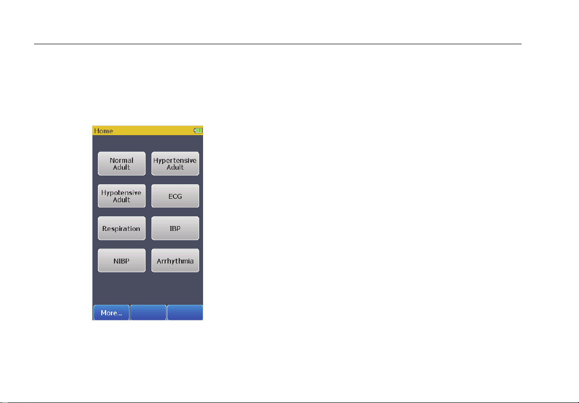
How to Turn On the Product
Push on the left side panel to turn on the Product.
Push for three seconds to turn off the Product.
When the self test is complete and no errors are sensed,
the Home screen in Figure 3 shows in the display.
Figure 3. Home Screen
gne102.jpg
All Product simulations and tests are set through the
controls on the Home screen.
How to Change the Display Language
To change the language used in the display:
1. From the home screen shown in Figure 3, touch
the More softkey.
2. Touch the Setup control.
3. Touch the Language control.
4. Touch or to scroll through the languages.
5. Touch the Save softkey to set the language and
go back to the Setup screen.
Touch the Cancel softkey to go back to the Setup screen
and not change the language.
10
Page 23

Vital Signs Simulator
Maintenance
Maintenance
The Product is a calibrated measurement instrument. Try
to prevent mechanical abuse that could change the
calibrated values. The Product has no internal userserviceable parts.
Warnings
For safe operation and maintenance of the
Product:
• Do not keep cells or batteries in a
container where the terminals can be
shorted.
• Connect the battery charger to
the mains power outlet before the
Product.
• Repair the Product before use if
the battery leaks.
• Remove batteries to prevent
battery leakage and damage to
the Product if it is not used for an
extended period.
• Do not short the battery terminals
together.
• Keep cells and battery packs
clean and dry. Clean dirty
connectors with a dry, clean
cloth.
• Use only Fluke Biomedical
approved power adapters to
charge the battery.
11
Page 24

ProSim™ 4
Getting Started
To prevent personal injury:
• Do not disassemble the battery.
• Batteries contain hazardous
chemicals that can cause burns
or explode. If exposure to
chemicals occurs, clean with
water and get medical aid.
• Do not put battery cells and
battery packs near heat or fire. Do
not put in sunlight.
• Do not disassemble or crush
battery cells and battery packs.
To prevent possible electrical shock, fire, or
personal injury:
• Remove the input signals before
you clean the Product.
• Use only specified replacement
parts.
• Have an approved technician
repair the Product.
How to Clean the Product
Caution
Do not pour fluid onto the Product surface;
fluid seepage into the electrical circuitry may
cause the Product to fail.
Do not use spray cleaners on the Product;
such action may force the cleaning fluid into
the Product and damage electronic
components.
Clean the Analyzer occasionally with a damp cloth and
mild detergent. Try to prevent the entrance of liquids.
Clean the adapter cables with the same precautions.
Examine them for damage and deterioration of the
insulation. Examine the connections for integrity. Keep
the transducer adapter clean and dry.
12
Page 25

Vital Signs Simulator
Maintenance
Battery Maintenance
For peak battery performance, charge the Product to
maximum charge once a month. If the Product is not to
be used for more than a month, keep it connected to the
charger.
Note
To get the specified performance, use the
specified battery charger that comes with this
Product.
When the battery gets low a low battery message shows
in the display.
When the battery discharges to a low level threshold, a
warning shows in the display to indicate the NIBP function
is disabled.
How to Charge the Battery
The battery charge level is shown in the upper right
corner of the display.
Shows when the ac/dc power
supply is connected
Shows the battery level when the
Product operates on the battery
The battery can be charged while it is in or out of the
Product. The charge rate is slower when the Product is
energized and the battery charger is on. To charge the
battery:
1. As shown in Figure 4, connect the ac/dc power
supply to the power connector on the battery pack.
2. Connect the ac/dc power supply to a power source.
The battery charge LED on the battery pack shows red or
green when the ac/dc power supply is connected to the
battery pack. When the LED is green, the battery is
charged.
When you have two or more battery packs, you can
charge one battery externally while you use the other to
energize the Product.
13
Page 26

ProSim™ 4
Getting Started
Battery LED
Figure 4. External Battery Charging Connection
gne022.eps
14
Page 27

Vital Signs Simulator
Maintenance
Battery Removal
The battery pack is easy to remove and replace. To
remove the battery pack:
1. Push down on the battery pack latch as shown in
Figure 5.
Push
Down
Figure 5. Battery Removal
2. Pull the battery pack from the Product.
To put the battery pack into the Product, align the battery
pack with the guides on the Product and push it into the
Product until the catch locks.
The ProSim 4 battery is not compatible with the
ProSim 6/8.
Pull Out
gne023.eps
15
Page 28

ProSim™ 4
Getting Started
General Specifications
Temperature
Operating ............................................................ 10 °C to 40 °C (50 °F to 104 °F)
Storage ............................................................... -20 °C to +60 °C (-4 °F to +140 °F)
Humidity ................................................................. 10 % to 90 % non-condensing
Altitude ................................................................... 3,000 meters (9,843 ft)
Size (L x W x H) ..................................................... 18.0 cm x 9.3 cm x 5.5 cm (7.1 in x 3.7 in x 2.2 in)
Display ................................................................... LCD Touch-Screen Color Display
Communication ..................................................... USB Port (for calibration and firmware updates only)
Power ..................................................................... Lithium-Ion rechargeable battery, 10.75 Wh, 3.7 V, 2900 mAh
Battery Charger ..................................................... 110 to 220 Vac, 50/60 Hz input, 6 V/3.5 A output. For best performance, the battery
Battery Life ............................................................ 4 hours (minimum), 40 NIBP cycles typical
Weight .................................................................... 0.88 kg (1.93 lb)
Safety ..................................................................... IEC 61010-1: Category II, Pollution Degree 2
Electromagnetic Compatibility (EMC)
International ........................................................ IEC 61326-1: Basic Electromagnetic Environment
USA (FCC) .......................................................... 47 CFR 15 subpart B
charger should be connected to a properly grounded ac receptacle.
CISPR 11: Group 1, Class A
Group 1: Equipment has intentionally generated and/or uses conductively-coupled
radio frequency energy that is necessary for the internal function of the equipment
itself.
Class A: Equipment is suitable for use in all establishments other than domestic and
those directly connected to a low-voltage power supply network that supplies
buildings used for domestic purposes. There may be potential difficulties in ensuring
electromagnetic compatibility in other environments due to conducted and radiated
disturbances.
Emissions that exceed the levels required by CISPR 11 can occur when the
equipment is connected to a test object.
16
Page 29

Vital Signs Simulator
Detailed Specifications
Detailed Specifications
Normal-Sinus-Rhythm Waveform
ECG Reference ...................................................... The ECG amplitudes specified are for Lead II (calibration), from the baseline to the peak
Normal Sinus Rhythm ........................................... 12-lead configuration with independent outputs referenced to right leg (RL). Output to 10
Amplitude ............................................................... 1.0 mV. Other leads are proportional to Lead II (reference lead) in percentage per:
Lead I .................................................................. 70
Lead II ................................................................. 100
Lead III ................................................................ 30
Lead V1 ............................................................... 24
Lead V2 ............................................................... 48
Lead V3 ............................................................... 100
Lead V4 ............................................................... 120
Lead V5 ............................................................... 112
Lead V6 ............................................................... 80
Amplitude Accuracy .............................................. ±5 % of setting Lead II
ECG Rate ................................................................ 30, 60, 80, 90, 120, 150, 180, 210, 240, 270, 300, and 320 BPM (Preset Hypotensive
Rate Accuracy ....................................................... ±1 % of setting
ECG Waveform Selection ..................................... Adult (80 ms) or neonatal (40 ms) QRS duration
Power-On Default .................................................. 60 BPM, 1.0 mV, adult QRS
Arrhythmia
Atrial Fibrillation .................................................... Coarse or fine
Premature Ventricular Contraction ..................... Left Ventricular
Ventricular Tachycardia ........................................ 160 or 200 BPM
of the R wave. All other leads are proportional.
Universal ECG Jacks, color-coded to AHA and IEC Standards.
condition is at 40 BPM)
17
Page 30

ProSim™ 4
Getting Started
Ventricular Fibrillation .......................................... Coarse or fine
Transvenous Pacer Pulse .................................... 75 BPM, left arterial, 3 mV amplitude on lead II, Accuracy ±10 %, 1.0 ms width
2nd Degree AV Block ............................................ Type 1
3rd Degree AV Block
Asystole
ECG-Performance-Testing
Amplitude .............................................................. 1 mV. Other leads are proportional to Lead II (reference lead) in percentage per:
Lead I .............................................................. 70
Lead II ............................................................. 100
Lead III ............................................................ 30
Lead V1 ........................................................... 24
Lead V2 ........................................................... 48
Lead V3 ........................................................... 100
Lead V4 ........................................................... 120
Lead V5 ........................................................... 112
Lead V6 ........................................................... 80
Square Wave ......................................................... 60 ms at 2.0 Hz
Respiration
Rate ........................................................................ 0 (OFF), 10 to 100 BrPM in 10 BrPM steps
Impedance Variations (Δ Ω) ................................. 1 Ω
Accuracy Delta ...................................................... ±(10 % + 0.05 ohm)
Baseline ................................................................. 500 Ω to circuit common, giving 1000 Ω between any two leads
Accuracy Baseline ................................................ ±5 %
Respiration Lead ................................................... LA or LL (default)
18
Page 31

Vital Signs Simulator
Detailed Specifications
Invasive Blood Pressure
Channels ................................................................ 1 electrically isolated from all other signals
BP Output ............................................................... Circular DIN 5-Pin
Input/output Impedance ........................................ 300 Ω ±10 %
Exciter Input Range ............................................... 2.0 to 16.0 V peak
Exciter-Input Frequency Range ........................... DC to 5000 Hz
Transducer Sensitivity .......................................... 5 μV/V/mmHg
Pressure Accuracy ................................................ ±(1 % of setting + 1 mmHg) Accuracy guaranteed for DC excitation only
Static Pressure ...................................................... 0, 80, 160, and 250 mmHg
Dynamic Waveforms
Synchronization ................................................... To ECG heartrate
Chambers simulated systolic/diastolic pressure:
Type IBP (Arterial) IBP (Left Ventrical)
Adult 60/30 60/0
Adult 120/80 120/0
Adult 150/100 150/0
Adult 200/150 200/0
Neonatal 35/15 35/0
Neonatal 70/40 70/0
Non-Invasive Blood Pressure
Pressure Units ....................................................... mmHg
Manometer (Pressure Meter)
Range .................................................................. 10 to 400 mmHg
Resolution ........................................................... 0.1 mmHg (for display purposes)
Accuracy.............................................................. ±(1 % reading +1 mmHg)
Pressure Source .................................................... Inflation bulb or device under test
19
Page 32

ProSim™ 4
Getting Started
NIBP Simulations
Pulse ................................................................... 2 mmHg max into 500 ml NIBP system
Volume of air moved ........................................... 1.0 ml max
Simulations ......................................................... Systolic/diastolic (MAP)
Adult ................................................................ 60/30 (40), 120/80 (93); 150/100 (117); and 200/150 (167)
Neonatal .......................................................... 35/15 (22) and 70/40 (50)
Repeatability ....................................................... Within ±2 mmHg (at maximal pulse size independent of device under test)
Synchronization .................................................. To ECG heartrate (maximal rate 120 BPM)
Leak Test
Target Pressure .................................................. 20 to 400 mmHg
Elapse time ......................................................... 0:30 to 5:00 minutes:seconds in 30 second steps
Leakage Rate ...................................................... 0 to 200 mmHg/minute
Internal Leak rate ................................................ <2 mmHg/min into 500 ml rigid volume
Pressure Relief Test Range ................................. 100 to 400 mmHg
Presets and Autosequences
Presets
Normal
Hypertensive
Hypotensive
Autosequences
Cardiac Failure sequence
Exercise sequence
Respiration sequence
Monitor testing sequence
20
 Loading...