

Page 1

ProSim™ 4
Vital Signs Simulator
PN FBC-0007
January 2011, Rev. 3, 2/15
© 2011-2015 Fluke Corporation. All rights reserved. Specifications are subject to change without notice.
All product names are trademarks of their respective companies.
Users Manual
Page 2

Warranty and Product Support
Fluke Biomedical warrants this instrument against defects in materials and workmanship for one year from
the date of original purchase OR two years if at the end of your first year you send the instrument to a
Fluke Biomedical service center for calibration. You will be charged our customary fee for such calibration.
During the warranty period, we will repair or at our option replace, at no charge, a product that proves to be
defective, provided you return the product, shipping prepaid, to Fluke Biomedical. This warranty covers the
original purchaser only and is not transferable. The warranty does not apply if the product has been
damaged by accident or misuse or has been serviced or modified by anyone other than an authorized
Fluke Biomedical service facility. NO OTHER WARRANTIES, SUCH AS FITNESS FOR A PARTICULAR
PURPOSE, ARE EXPRESSED OR IMPLIED. FLUKE SHALL NOT BE LIABLE FOR ANY SPECIAL,
INDIRECT, INCIDENTAL OR CONSEQUENTIAL DAMAGES OR LOSSES, INCLUDING LOSS OF DATA,
ARISING FROM ANY CAUSE OR THEORY.
This warranty covers only serialized products and their accessory items that bear a distinct serial number
tag. Recalibration of instruments is not covered under the warranty.
This warranty gives you specific legal rights and you may also have other rights that vary in different
jurisdictions. Since some jurisdictions do not allow the exclusion or limitation of an implied warranty or of
incidental or consequential damages, this limitation of liability may not apply to you. If any provision of this
warranty is held invalid or unenforceable by a court or other decision-maker of competent jurisdiction, such
holding will not affect the validity or enforceability of any other provision.
7/07
Page 3

Notices
All Rights Reserved
Copyright 2015, Fluke Biomedical. No part of this publication may be reproduced, transmitted, transcribed, stored in a
retrieval system, or translated into any language without the written permission of Fluke Biomedical.
Copyright Release
Fluke Biomedical agrees to a limited copyright release that allows you to reproduce manuals and other printed materials
for use in service training programs and other technical publications. If you would like other reproductions or distributions,
submit a written request to Fluke Biomedical.
Unpacking and Inspection
Follow standard receiving practices upon receipt of the instrument. Check the shipping carton for damage. If damage is
found, stop unpacking the instrument. Notify the carrier and ask for an agent to be present while the instrument is
unpacked. There are no special unpacking instructions, but be careful not to damage the instrument when unpacking it.
Inspect the instrument for physical damage such as bent or broken parts, dents, or scratches.
Technical Support
For application support or answers to technical questions, either email techservices@flukebiomedical.com or call
1-800-850-4608 or 1-440-248-9300. In Europe, email techsupport.emea@flukebiomedical.com or call +31-40-2965314.
Claims
Our routine method of shipment is via common carrier, FOB origin. Upon delivery, if physical damage is found, retain all
packing materials in their original condition and contact the carrier immediately to file a claim. If the instrument is delivered
in good physical condition but does not operate within specifications, or if there are any other problems not caused by
shipping damage, please contact Fluke Biomedical or your local sales representative.
Returns and Repairs
Return Procedure
All items being returned (including all warranty-claim shipments) must be sent freight-prepaid to our factory location. When
you return an instrument to Fluke Biomedical, we recommend using United Parcel Service, Federal Express, or Air Parcel
Post. We also recommend that you insure your shipment for its actual replacement cost. Fluke Biomedical will not be
responsible for lost shipments or instruments that are received in damaged condition due to improper packaging or
handling.
Use the original carton and packaging material for shipment. If they are not available, we recommend the following guide
for repackaging:
Use a double–walled carton of sufficient strength for the weight being shipped.
Use heavy paper or cardboard to protect all instrument surfaces. Use nonabrasive material around all
projecting parts.
Use at least four inches of tightly packed, industry-approved, shock-absorbent material around the
Returns for partial refund/credit:
Every product returned for refund/credit must be accompanied by a Return Material Authorization (RMA) number,
obtained from our Order Entry Group at 1-440-498-2560.
Repair and calibration:
To find the nearest service center, go to www.flukebiomedical.com/service or
To ensure the accuracy of the Product is maintained at a high level, Fluke Biomedical recommends the product
be calibrated at least once every 12 months. Calibration must be done by qualified personnel. Contact your local
Fluke Biomedical representative for calibration.
instrument.
In the U.S.A.:
Cleveland Calibration Lab
Tel: 1-800-850-4608 x2564
Email: globalcal@flukebiomedical.com
Everett Calibration Lab
Tel: 1-888-99 FLUKE (1-888-993-5853)
Email: service.status@fluke.com
In Europe, Middle East, and Africa:
Eindhoven Calibration Lab
Tel: +31-40-2675300
Email: ServiceDesk@fluke.com
In Asia:
Everett Calibration Lab
Tel: +425-446-6945
Email: service.international@fluke.com
PN FBC-0007
January 2011, Rev. 3, 2/15
© 2011-2015 Fluke Corporation. All rights reserved. Specifications are subject to change without notice.
All product names are trademarks of their respective companies.
Page 4

Certification
This instrument was thoroughly tested and inspected. It was found to meet Fluke Biomedical’s manufacturing
specifications when it was shipped from the factory. Calibration measurements are traceable to the National Institute of
Standards and Technology (NIST). Devices for which there are no NIST calibration standards are measured against inhouse performance standards using accepted test procedures.
WARNING
Unauthorized user modifications or application beyond the published specifications may result in electrical shock hazards
or improper operation. Fluke Biomedical will not be responsible for any injuries sustained due to unauthorized equipment
modifications.
Restrictions and Liabilities
Information in this document is subject to change and does not represent a commitment by Fluke Biomedical.
Changes made to the information in this document will be incorporated in new editions of the publication. No
responsibility is assumed by Fluke Biomedical for the use or reliability of software or equipment that is not
supplied by Fluke Biomedical, or by its affiliated dealers.
Manufacturing Location
The ProSim 4 is manufactured at Fluke Biomedical, 6920 Seaway Blvd., Everett, WA, U.S.A.
Page 5

Table of Contents
Title Page
Introduction ............................................................................................ 1
Intended Use ......................................................................................... 1
Safety Information ................................................................................. 2
Symbols ................................................................................................. 3
Unpack the Product ............................................................................... 3
Accessories ........................................................................................... 4
Instrument Familiarization ..................................................................... 5
How to Turn On the Product .................................................................. 7
ECG Simulation ..................................................................................... 8
Arrhythmia Simulation ........................................................................... 10
How to Set an Arrhythmia ECG Waveform ....................................... 11
How to Output a Performance Wave ................................................. 11
Respiration Simulation .......................................................................... 11
Non-Invasive Blood Pressure Simulation and Tests ............................. 12
How to Set the Non-Invasive Blood Pressure Parameters ................ 12
How to Do an NIBP Monitor Test ...................................................... 14
How to Do a Pressure Relief Test ..................................................... 14
How to Do a Leak Test ...................................................................... 15
How to Check a Manometer .............................................................. 17
Invasive Blood Pressure Simulation ...................................................... 18
Autosequences ...................................................................................... 19
Setup Features ...................................................................................... 22
How to Set the Backlight Intensity Level ........................................... 22
How to Change the Language for the Display ................................... 23
How to Show Instrument Information in the Display .......................... 24
Maintenance .......................................................................................... 24
How to Clean the Product .................................................................. 25
Battery Maintenance .......................................................................... 25
How to Charge the Battery ............................................................ 26
Battery Removal ............................................................................ 27
General Specifications .......................................................................... 27
Detailed Specifications .......................................................................... 28
Normal-Sinus-Rhythm Waveform ...................................................... 28
Arrhythmia ......................................................................................... 28
ECG-Performance-Testing ................................................................ 29
Respiration ........................................................................................ 29
i
Page 6

ProSim™ 4
Users Manual
Invasive Blood Pressure .................................................................... 29
Non-Invasive Blood Pressure ............................................................ 29
Presets and Autosequences .............................................................. 30
Glossary ............................................................................................................ A-1
ii
Page 7

List of Tables
Table Title Page
1. Simulation Types ....................................................................................... 1
2. Symbols ..................................................................................................... 3
3. Standard Accessories ............................................................................... 4
4. Optional Accessories ................................................................................. 4
5. Product Controls and Connections ............................................................ 5
6. Display Features ....................................................................................... 6
7. Pre-Defined Patient Simulations ............................................................... 8
8. ECG Lead Amplitudes ............................................................................... 10
9. Autosequences .......................................................................................... 21
iii
Page 8

ProSim™ 4
Users Manual
iv
Page 9

List of Figures
Figure Title Page
1. Home Screen ............................................................................................ 7
2. ECG Connections ...................................................................................... 9
3. ECG Screen .............................................................................................. 9
4. Arrhythmia Screens ................................................................................... 10
5. Respiration Screen .................................................................................... 11
6. Non-Invasive Blood Pressure Test Connections ....................................... 12
7. Blood Pressure Cuff Mandrel Sizes .......................................................... 13
8. Non-Invasive Blood Pressure Screen ....................................................... 14
9. Pressure Relief Test Screen ..................................................................... 15
10. Leak Test Screen ...................................................................................... 16
11. Leak Test Results Screen ......................................................................... 17
12. Manometer Check Connections ................................................................ 17
13. Invasive Blood Pressure Connections ....................................................... 18
14. Invasive Blood Pressure Screen ............................................................... 18
15. Static Pressure Screen .............................................................................. 19
16. Monitor Testing Autosequence Screen ..................................................... 19
17. Monitor Testing Autosequence Steps Screen ........................................... 20
18. Setup Screen ............................................................................................. 22
19. Backlight Screen ....................................................................................... 22
20. Language Screen ...................................................................................... 23
21. Instrument Information Screen .................................................................. 24
22. External Battery Charging Connections .................................................... 26
23. Battery Removal ........................................................................................ 27
v
Page 10

ProSim™ 4
Users Manual
vi 1
Page 11

Introduction
The ProSim 4 Vital Signs Simulator (the Product) is a portable vital signs
monitor functional tester.
The product simulates:
• ECG Functions
• Respiration
• Invasive and non-invasive Blood Pressure
When the term simulation is used in connection with ECG, respiration, IBP, or
NIBP, the simulation type shown in Table 1 is used in this Product.
Table 1. Simulation Types
Parameter Simulation Type
ECG Electrical
Respiration Electrical
IBP Electrical
NIBP Pneumatic
Intended Use
The Product is intended to be used to test and verify the basic operation of
patient monitoring devices or systems used to monitor various physiological
parameters of a patient, including ECG, respiration, invasive blood pressure, and
non-invasive blood pressure.
The intended user is a trained biomedical equipment technician who performs
periodic preventative maintenance checks on patient monitors in service. Users
can be associated with Hospitals, clinics, original equipment manufacturers and
independent service companies that repair and service medical equipment. The
end user is an individual, trained in medical instrumentation technology.
This Product is intended to be used in the laboratory environment and is not
intended for use on patients, or to test devices while connected to patients. This
Product is not intended to be used to calibrate medical equipment. It is intended
for over the counter use.
Page 12

ProSim™ 4
Users Manual
Safety Information
In this manual, a Warning identifies hazardous conditions and actions that could
cause bodily harm or death. A Caution identifies conditions and actions that
could damage the Analyzer, the equipment under test, or cause permanent loss
of data.
Warnings
To prevent personal injury, use the Product only as specified,
or the protection supplied by the Product can be compromised.
To prevent possible electrical shock, fire, or personal injury:
• Do not use and disable the Product if it is damaged.
• The battery door must be closed and locked before you
operate the Product.
• Remove all probes, test leads, and accessories that are not
necessary for the measurement.
• Do not use the Product around explosive gas, vapor, or in
damp or wet environments.
• Do not use the Product if it operates incorrectly.
• Do not connect the Product to a patient or equipment
connected to a patient. The Product is intended for
equipment evaluation only and should never be used in
diagnostics, treatment, or any other capacity where the
Product would come in contact with a patient.
• Read all safety Information before you use the Product.
• Examine the case before you use the Product. Look for
cracks or missing plastic. Carefully look at the insulation
around the terminals.
• Carefully read all instructions.
2
Page 13

Vital Signs Simulator
Symbols
Symbols
Table 2 is a list of symbols found in this manual or on this Product.
Table 2. Symbols
Symbol Description Symbol Description
Risk of danger. Important information.
See manual.
Conforms to European Union directives.
Conforms to relevant Australian EMC
standards
Spent Lithium batteries should be disposed of by a qualified recycler or hazardous materials
handler per local regulations. Contact your authorized Fluke Service Center for recycling
information.
This product complies with the WEEE Directive (2002/96/EC)marking requirements. The affixed
label indicates that you must not discard this electrical/electronic product in domestic household
waste. Product Category: With reference to the equipment types in the WEEE Directive Annex
I, this product is classed as category 9 "Monitoring and Control Instrumentation" product. Do
not dispose of this product as unsorted municipal waste. Go to Fluke’s website for recycling
information.
Unpack the Product
Carefully unpack all items from the box and check that you have these items:
• ProSim 4
• Getting Started Manual
• Users Manual CD
• Carrying Case
Hazardous voltage. Risk of electric
shock.
Input jack for the DC output of the
AC/DC supply connector.
Conforms to relevant North American
Safety Standards.
• Power Cord
• AC/DC Power Supply
• Manual Inflation Bulb
• NIBP Cuff Adapters
3
Page 14

ProSim™ 4
Users Manual
Accessories
Available Product accessories are shown in Tables 3 and 4.
Table 3. Standard Accessories
Item Fluke Biomedical Part Number
ProSim 4 Getting Started Manual 3931478
ProSim 4 Users Manual CD 3931519
AC/DC Power Supply 3978380
US 284174
Schuko 769422
AC Power Cord
Manual inflation bulb 2461946
Set of NIBP Cuff Adapters 2391882
Carrying Case 4026799
[1] Product shipped to Brazil also includes a US power cord.
Battery pack 4026823
USB Cable, Mini Series B, 1 meter long 4034393
NIBP Mandrel Set 4308086
Modules to convert ECG snap adapter to 4 mm and 3.2 mm
ECG banana adapter as part of optional accessories – For
International use only
UK 769455
Japan 284174
Australia 658641
[1]
Brazil
Item Fluke Biomedical Part Number
3841347
Table 4. Optional Accessories
4026551
4
IBP Cables See your Fluke Biomedical Distributor
Page 15
Vital Signs Simulator
Instrument Familiarization
Instrument Familiarization
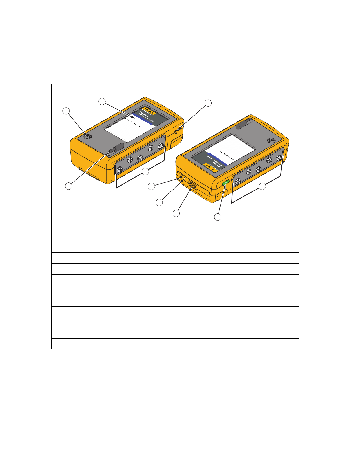
Table 5 is a list of Product controls and connections.
Table 5. Product Controls and Connections
1
5
3
4
6
7
8
2
3
9
Item Name Description
LCD Display Color LCD touch-sensitive display
gne026.eps
Mini-Series B Connector For firmware updates and calibration
ECG Posts Connection posts for Device Under Test (DUT) ECG leads
Air Port Connector Pressure port for NIBP cuff and monitor
IBP Channel 1 Connector Connector to an IBP input of the patient monitor
DC Power Connector Connector for the AC/DC power supply
Battery LED Indicates when the battery is charged
Battery Latch Locks battery in the Product
Power Button Turns on and off the Product
5
Page 16
ProSim™ 4
Users Manual
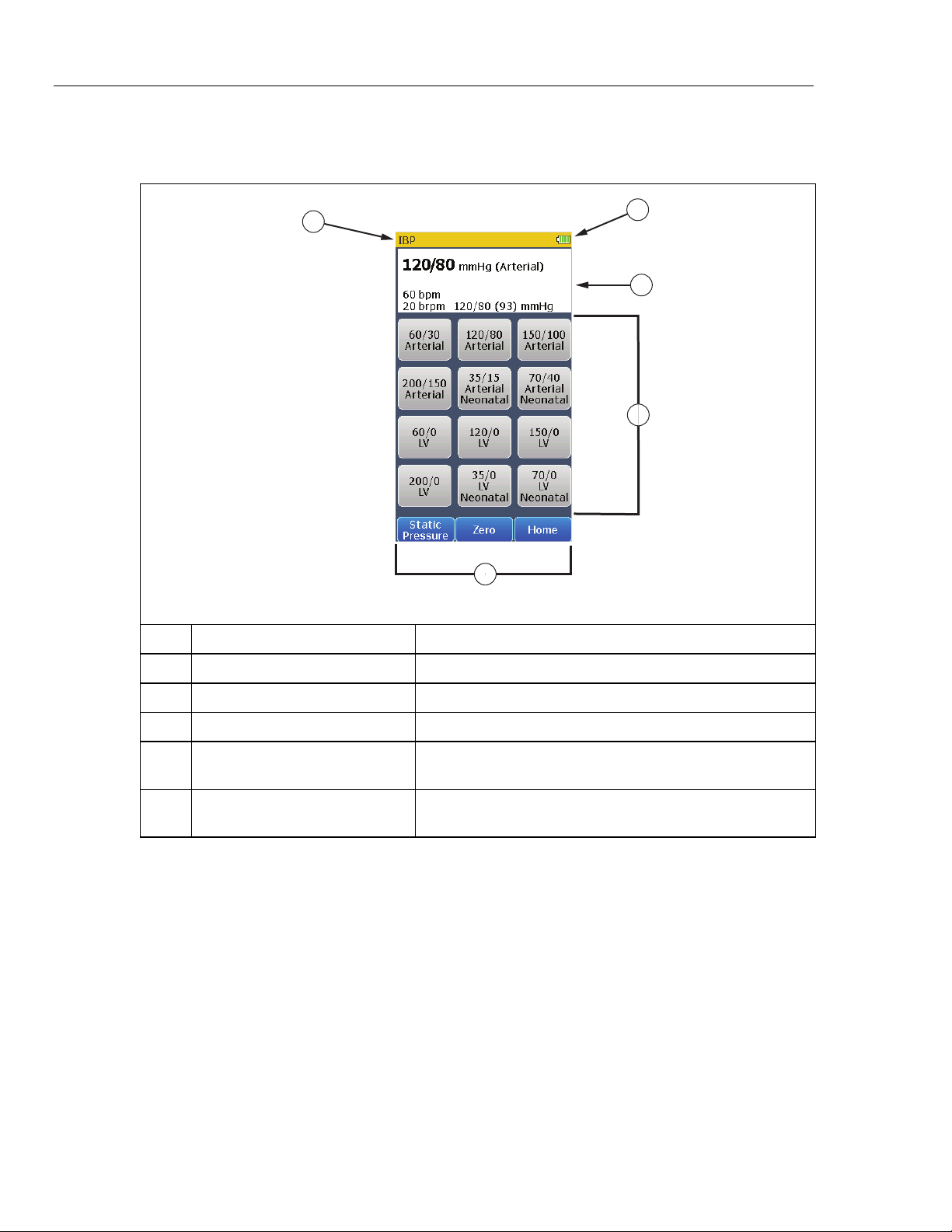
Table 6 is a list of display features.
Table 6. Display Features
1
5
2
3
4
Item Name Description
gne010.eps
Name Screen name
Battery ICON that indicates the charge level of the battery.
Simulation parameters Shows the simulation parameter values
Controls
Softkeys
Touch sensitive controls to set simulation parameters and
Product features.
Three touch sensitive controls that activate the function shown
inside the control.
6
Page 17

Vital Signs Simulator
How to Turn On the Product
How to Turn On the Product
Push on the left side panel to turn on the Product. Push for three
seconds to turn off the Product.
When the self test is complete and no errors are sensed, page 1 of the Home
screen in Figure 1 shows in the display. All Product simulations and tests are set
through the controls on the Home screen.
Page 1 Page 2
Figure 1. Home Screen
gne002.eps
Note
When page 1 or page 2 of the Home screen shows in the display, all
simulation outputs are disabled.
From page 1 of the Home screen, three pre-defined conditions for simulations
can be used to set all the simulation functions. These pre-defined conditions are
set when you touch Normal Adult, Hypertensive Adult, or Hypotensive Adult
on the display. The pre-defined simulation variables can not be changed. Table 7
lists the parameter values for each pre-defined simulation.
7
Page 18

ProSim™ 4
Users Manual
Table 7. Pre-Defined Patient Simulations
Simulation Name Parameter Pre-Set Value
Wave Form NSR (Adult)
ECG Rate 60 bpm
Normal
Hypertensive
Hypotensive
Control of heart rate, respiration, invasive blood pressure, and non-invasive
blood pressure simulations are also accessed through the controls on page 1 of
the Home screen. A number of arrythmias are set through the Arrhythmia
control. Refer to the applicable section to learn more about each simulation
function.
Respiration Rate 20 bpm
IBP Channel 1 120/80 mmHg (Art)
NIBP 120/80 (93) mmHg
Wave Form NSR (Adult)
ECG Rate 120 bpm
Respiration Rate 40 bpm
IBP Channel 1 200/150 mmHg (Art)
NIBP 200/150 (167) mmHg
Wave Form NSR (Adult)
ECG Rate 40 bpm
Respiration Rate 10 bpm
IBP Channel 1 60/0 mmHg (LV)
NIBP 60/30 (40) mmHg
8
To show page 2 of the Home screen, push the More softkey. Page 2 shows
controls that access autosequences, pressure and leak tests, and all setup
parameters. To go back to page 1 of the Home screen, push the Back softkey.
ECG Simulation
The Product simulates normal heart signals (ECG) as well as a variety of heart
arrhythmias. You set adult or neonatal simulation and change the heart rate
(beats per minute) through the ECG control.
To measure the ECG performance of a monitor, connect the Product to the
monitor as shown in Figure 2. A maximum of ten ECG leads can be connected to
the Product.
Page 19

Vital Signs Simulator
ECG Simulation
ProSim 4
V2
V3
V4
V5
V6
RA
LL
LA
RL
V1
Patient
Monitor
ECG
Cable
gne018.eps
Figure 2. ECG Connections
Touch the ECG control in the Home screen to show the screen in Figure 3 in the
display.
Figure 3. ECG Screen
gne003.bmp
9
Page 20
ProSim™ 4
Users Manual
Heart rate, respiration, invasive blood pressure, and non-invasive blood pressure
parameters are shown at the top of the screen. To change the heart rate, touch
one of the pre-defined heart rate controls in the display.
The ECG function can be set to an adult or neonatal ECG signal. To change
between Adult and Neonatal, touch the softkey control in the lower-left corner of
the display. The softkey text will change to the one value not set. For example,
when Neonatal is shown in the softkey, an adult ECG signal is simulated.
Touch the Home softkey to go back to the Home screen.
Table 8 shows the percentage of the signal amplitude value that is put on each
ECG lead.
Table 8. ECG Lead Amplitudes
Waveform I II III V1 V2 V3 V4 V5 V6
Normal Sinus & Performance 70 % 100 % 30 % 24 % 48 % 100 % 120 % 112 % 80 %
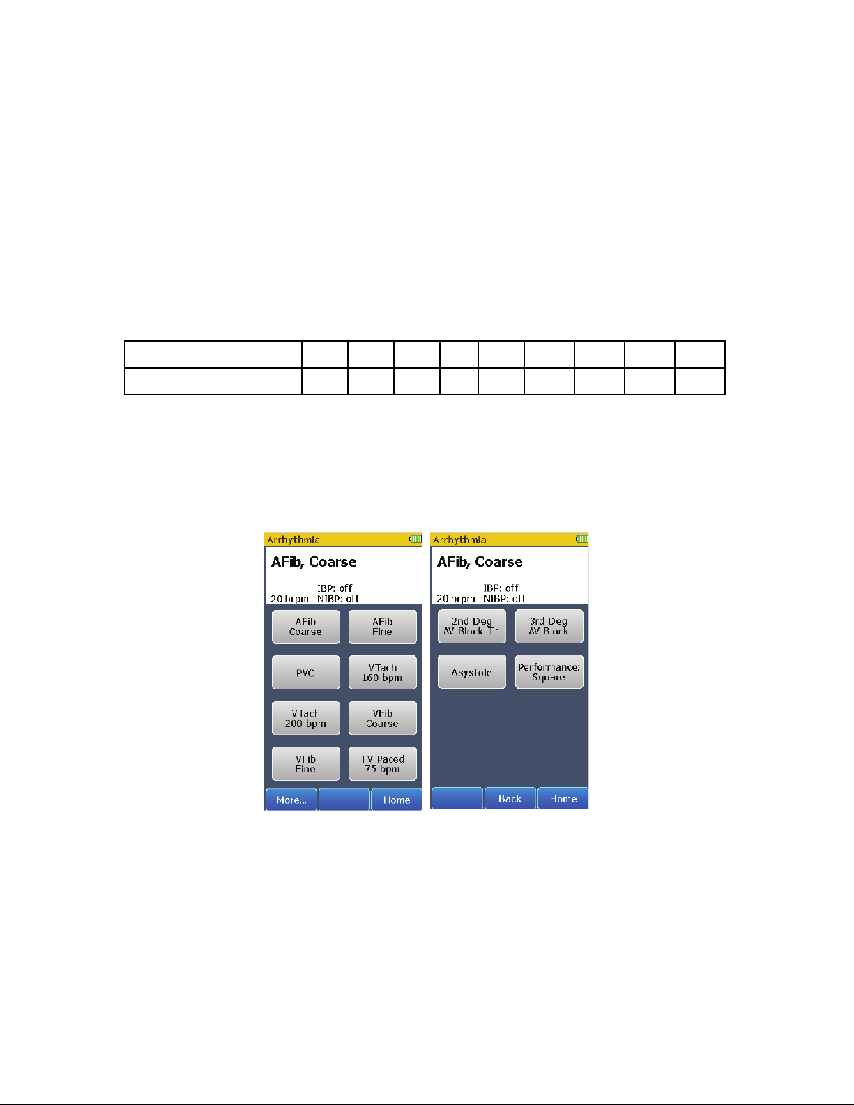
Arrhythmia Simulation
The Product can simulate a number of arrhythmias on the ECG leads. As well as
physiological waveforms, the Product can supply a signal to measure the
performance of an ECG monitor. To do an arrhythmia simulation or do a monitor
test with a performance wave, touch the Arrhythmia control in the Home screen.
Page 1 of the screens in Figure 4 shows in the display.
10
Page 1 Page 2
Figure 4. Arrhythmia Screens
gne008.bmp
Page 21
Vital Signs Simulator
Respiration Simulation
How to Set an Arrhythmia ECG Waveform
Connect the Product to an ECG monitor as shown in Figure 2. The Product sets
the coarse atrial fibrillation waveform when the Arrhythmia screen shows in the
display. There are eight arrhythmia waveform controls shown in page 1 of the
Arrhythmia screen. Controls for more arrhythmia waveforms and a performance
wave are shown in page 2 when the More softkey is touched.
The simulated arrhythmia waveform and the respiration rate are shown at the top
of the display. The invasive and non-invasive blood pressure simulations are
disabled when an arrhythmia waveform is simulated. To change the arrhythmia
waveform, touch an arrhythmia control in page 1 or page 2 of the Arrhythmia
screens.
Touch the Home softkey to go back to the Home screen.
How to Output a Performance Wave
One performance wave can be output on the ECG leads for an ECG monitor test.
To output a square wave on the ECG leads:
1. Touch the Arrhythmia control in the Home screen.
2. Touch the More softkey to show page 2 of the Arrhythmia screens.
3. Touch the Performance: Square control in the display.
A square wave is output on the ECG leads until a control is touched or the Home
softkey is touched.
Touch the Home softkey to go back to the Home screen.
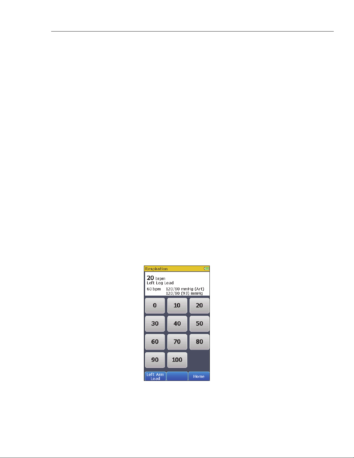
Respiration Simulation
The Product simulates respiration on the left leg or left arm ECG lead. To set a
respiration simulation parameter, touch the Respiration control in the Home
screen to show the screen in Figure 5 in the display.
Figure 5. Respiration Screen
gne004.bmp
11
Page 22

ProSim™ 4
Users Manual
The breaths per minute (brpm), heart rate (bpm), invasive and non-invasive
blood pressure simulation parameters are shown at the top of the display. To set
the breath rate, touch one of the pre-defined respiration rates shown in the
display.
To change which ECG lead the respiration simulation will be on, touch the
softkey in the lower-left corner of the display.
The softkey text will change to the one value not set. For example, when Left
Arm Lead is shown in the softkey, the respiration simulation will be on the left leg
ECG lead.
Touch the Home softkey to go back to the Home screen.
Non-Invasive Blood Pressure Simulation and Tests
The Product simulates blood pressure for non-invasive blood pressure monitors.
Each blood pressure variable can be set through the display controls. The
Product also does leak and pressure relief tests.
How to Set the Non-Invasive Blood Pressure Parameters
To do a non-invasive blood pressure simulation, connect the Product to a blood
pressure cuff and monitor as shown in Figure 6.
Blood Pressure Cuff
Wraps around mandrel.
Patient
Monitor
Mandrel
Dual hose system: connect Cuff Adapter to
hose marked “Sense”. If both hoses are
unmarked, connect Cuff Adapter to either
hose.
Figure 6. Non-Invasive Blood Pressure Test Connections
ProSim 4
Must be connected closer
to the cuff than monitor.
gne020.eps
12
Page 23

Vital Signs Simulator
Non-Invasive Blood Pressure Simulation and Tests
Figure 7 shows the blood pressure cuff mandrel sizes.
Cap
Large Adult
Adult
Small Adult
Child
Cap
Figure 7. Blood Pressure Cuff Mandrel Sizes
Small Child
Neonatal
fcv011.eps
13
Page 24

ProSim™ 4
Users Manual
To access the non-invasive blood pressure parameters, touch the NIBP control
in the Home screen to show the screen in Figure 8 in the display.
Figure 8. Non-Invasive Blood Pressure Screen
The non-invasive blood pressure, heart rate, respiration, and the invasive blood
pressure parameters are shown at the top of the display. To change the noninvasive blood pressure, touch one of the pre-defined blood pressure controls in
the display.
The Product can simulate four adult and two neonatal blood pressures. When
set, the pulse volume is set to the default for that simulation: 1.0 ml for Adult,
0.5 ml for Neonatal.
Touch the Home softkey to go back to the Home screen.
How to Do an NIBP Monitor Test
To do an accuracy test on an NIBP monitor:
1. Connect the NIBP monitor to the Product as shown in Figure 6.
2. Start an NIBP pressure cycle on the monitor. Refer to the monitor manual as
necessary. After you start the blood pressure measurement cycle:
• The blood pressure cuff inflates around the mandrel.
• The Product starts blood pressure simulation when the pressure is over
10 mmHg. The heart beat simulation starts and stops at the systolic and
diastolic pressures set into the Product.
gne005.bmp
14
• The NIBP monitor interprets and shows the measured blood pressure
values and heart rate when the test stops.
How to Do a Pressure Relief Test
The pressure relief test measures the pressure in a pneumatic system until the
Product senses a drop in pressure as occurs when the relief valve opens. Or the
test stops if the pressure gets to the target pressure and no relief is sensed.
Note
Put the NIBP monitor in “calibrate” or “service” mode to close the
vent valve, so the user can inflate the pneumatic system. Refer to
the service manual for the NIBP monitor.
Page 25

Vital Signs Simulator
Non-Invasive Blood Pressure Simulation and Tests
To do a pressure relief test:
1. Touch the More softkey in the Home screen.
2. Touch the Pressure Relief Test control to show the screen in Figure 9 in the
display.
3. Manually increase the pressure in the NIBP pneumatic system.
When the Product senses a sharp drop in pressure, the test stops. The Product
shows “Relief Valve = Tripped” in the display and the measured pressure when
the valve opened. It is recommended you do three pressure relief tests in case
the relief valve is intermittent. To do the pressure relief test again, touch the
Clear softkey and do step 3 above.
Touch the Home softkey to go back to the Home screen.
How to Do a Leak Test
The leak test measures leaks in a non-invasive blood pressure monitor, the
hoses connected to the monitor, and the pressure cuff.
Before you do a pressure leak test on a monitor, do the pressure
leak test without the monitor. This measures the leak rate of the
hoses and pressure cuff. Use this leak rate to offset the rate of the
full system with the monitor connected.
Put the NIBP monitor in “calibrate” or “service” mode to close the
vent valve, so the user can inflate the pneumatic system. Refer to
the service manual for the NIBP monitor.
Figure 9. Pressure Relief Test Screen
Note
Note
gne009.bmp
Note
If the NIBP device has an internal system leak test or one that vents
the cuff inflation pneumatic circuit to the atmosphere when idle, refer
to the NIBP monitor operators manual for the recommended test
protocol.
Connect the Product to the monitor and cuff as shown in Figure 6.
15
Page 26

ProSim™ 4
Users Manual
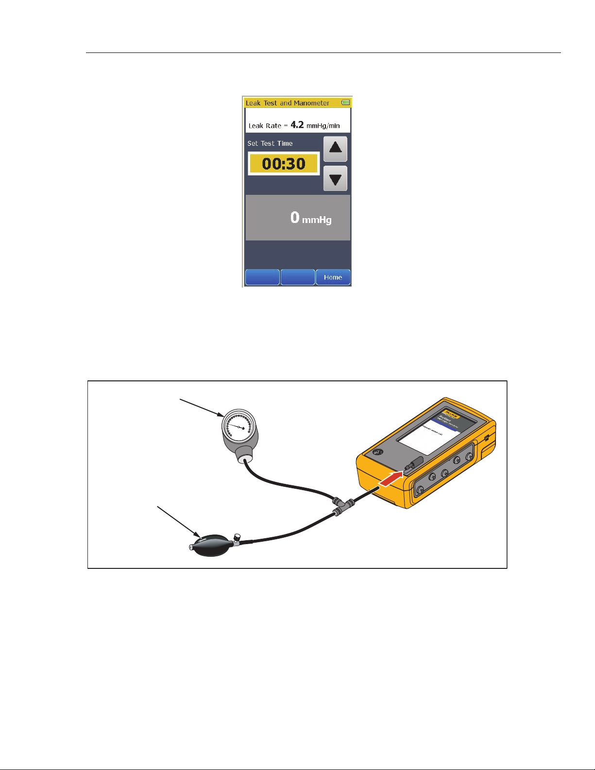
To do a leak test:
1. Touch the More softkey.
2. Touch the Leak Test and Manometer control to show the screen shown in
Figure 10 in the display.
Figure 10. Leak Test Screen
gne011.bmp
3. Touch or to set the test time for the leak test. The maximum test time is
5 minutes and the minimum test time is 30 seconds (default).
4. Manually increase the pressure in the pneumatic system to the pressure at
which the test is to start. When the measured pressure is 10 mmHg or higher,
the left softkey shows Start.
5. Touch the Start softkey. The timer counts down the test time.
16
Page 27
Vital Signs Simulator
Non-Invasive Blood Pressure Simulation and Tests
When the time expires, the leak rate is shown in the display. See Figure 11.
Touch the Home softkey to go back to the Home screen.
How to Check a Manometer
To check a manometer, connect the Product to the manometer and manual
pump bulb as shown in Figure 12.
Blood Pressure
Gauge
Squeeze
Pressure Pump
Figure 12. Manometer Check Connections
Figure 11. Leak Test Results Screen
ProSim 4
gne025.bmp
gne024.eps
1. Touch the More softkey.
2. Touch the Leak Test and Manometer control to show the screen shown in
Figure 10 in the display.
3. Squeeze the manual pump bulb to pressurize the line.
4. Check the value shown on the pressure gauge against the measurement in
the Product display.
Relieve the pressure through the pump relief valve before you remove the hose
from the Product.
17
Page 28

ProSim™ 4
Users Manual
Note
When the battery discharges to a low level threshold, all NIBP
functions may be disabled.
Invasive Blood Pressure Simulation
The Product can simulate an invasive blood pressure transducer. To do an
invasive blood pressure simulation, connect the Product to the monitor as shown
in Figure 13.
ProSim 4
IBP Cable
Patient
Monitor
Figure 13. Invasive Blood Pressure Connections
gne021.eps
To access the invasive blood pressure parameters, touch the IBP control in the
Home screen to show the screen in Figure 14 in the display.
Figure 14. Invasive Blood Pressure Screen
gne006.bmp
18
The invasive blood pressure, heart rate, respiration, and the non-invasive blood
pressure parameters are shown at the top of the display. To change the invasive
blood pressure, touch one of the pre-defined blood pressure controls in the
display.
To zero the simulated output, touch the Zero softkey.
To set a static IBP pressure signal to the IBP monitor, touch the Static Pressure
softkey from the IBP screen. The static pressure screen in Figure 15 shows in
the display.
Page 29

Vital Signs Simulator
Autosequences
To set the simulated pressure, touch one of the pre-defined static pressure
controls.
Touch the Home softkey to go back to the Home screen.
Autosequences
Autosequences are a series of steps that change the output of the Product
automatically. For example, to do a monitor test, you could set normal ECG then
wait some time. Then touch Hypertensive and wait more time, then touch
Hypotensive and wait. The monitor testing autosequence does these changes
for you automatically. Each step of the monitor testing autosequence sets
simulation parameters and after the allotted time period, it does the subsequent
step.
To do an autosequence:
1. Touch the More softkey if it is shown in the Home screen.
2. Touch one of the autosequence controls to show the autosequence steps in
the display. The Monitor Testing autosequence is shown in Figure 16.
Figure 15. Static Pressure Screen
gne007.bmp
Figure 16. Monitor Testing Autosequence Screen
gne012.bmp
19
Page 30

ProSim™ 4
Users Manual
The autosequence above, shows the sequence steps. Some autosequences
stop at the last step. The screen also shows that the length of time to complete
the autosequence is 3 minutes and the length of time for each step is
60 seconds.
Touch the Home softkey to go back to the second page of the Home screen.
3. Touch the Start softkey to start the sequence and show the screen in
Figure 17 in the display.
Figure 17. Monitor Testing Autosequence Steps Screen
gne013.bmp
The top part of the display shows the simulation parameters and their values.
These parameter values update at each autosequence step. The middle part of
the display shows which step the autosequence is on and how much time is left
for the step. The sequence timer shows the length of time to complete all steps of
the autosequence. If this is an autosequence that repeats, the sequence timer
resets to total sequence time when the sequence starts step one.
20
Page 31

Vital Signs Simulator
Autosequences
Push to abort the step and move to the subsequent step. When the
autosequence has moved to step two, shows in the display. Touch to
pause the step. shows in the display when the auto sequence is paused.
Push to continue the step for the time left when the step was paused.
To abort the autosequence, touch the Stop softkey and go back to the
autosequence view screen.
Table 9 is a list of autosequences that are built into the Product.
Table 9. Autosequences
Autosequence Sequence Steps Run Time
ECG 80 bpm, IBP Off, NIBP Off, and Respiration Off 00:45
ECG PVC (LV), IBP Off, NIBP Off, and Respiration Off 00:30
Cardiac Failure
xercise
Respiration
Monitor Testing
ECG VTach (LV) 160 bpm, IBP Off, NIBP Off, and Respiration Off 00:30
ECG VFib Coarse, IBP Off, NIBP Off, and Respiration Off 00:30
ECG Asystole, IBP Off, NIBP Off, and Respiration Off 00:15
STOP Total Time 02:30
ECG 60 bpm, IBP Off, NIBP Off, and Respiration Off 00:30
ECG 90 bpm, IBP Off, NIBP Off, and Respiration Off 00:30
ECG 120 bpm, IBP Off, NIBP Off, and Respiration Off 00:30
ECG 150 bpm, IBP Off, NIBP Off, and Respiration Off 00:30
ECG 90 bpm, IBP Off, NIBP Off, and Respiration Off 00:30
ECG 60 bpm, IBP Off, NIBP Off, and Respiration Off 00:30
REPEAT Total Time 03:00
ECG 60 bpm, IBP Off, NIBP Off, and Respiration 110 brpm 00:30
ECG 60 bpm, IBP Off, NIBP Off, and Respiration 60 brpm 00:30
ECG 60 bpm, IBP Off, NIBP Off, and Respiration 20 brpm 00:30
ECG 60 bpm, IBP Off, NIBP Off, and Respiration 0 brpm (Apnea) 00:12
REPEAT Total Time 01:42
ECG 120 bpm, IBP 200/150 (Art), NIBP 200/150 (167), and
Respiration 40 brpm
ECG 60 bpm, IBP 120/80 (Art), NIBP 120/80 (93), and Respiration
20 brpm
ECG 40 bpm, IBP 60/0 (LV), NIBP 60/30 (40), and Respiration
10 brpm
STOP Total Time 04:30
01:30
01:30
01:30
21
Page 32
ProSim™ 4
Users Manual
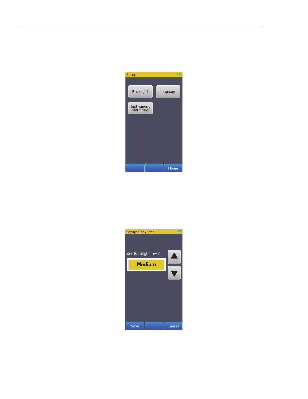
Setup Features
The Product has a number of functions that are accessed through the Setup
control. Touch the Setup control on page 2 in the Home screen to show the
Setup screen in Figure 18 in the display.
Figure 18. Setup Screen
Touch the Home softkey to go back to the Home screen.
How to Set the Backlight Intensity Level
To change the intensity level of the backlight:
1. From the Setup screen, touch the Backlight control to show the screen in
Figure 19 in the display.
gne014.bmp
22
Figure 19. Backlight Screen
gne017.bmp
Page 33

Vital Signs Simulator
Setup Features
2. Touch or to increase or decrease the backlight level. There are only
three levels: High, Medium, and Low.
3. Touch the Save softkey to set the level and go back to the Setup screen.
Touch the Cancel softkey to go back to the Setup screen and not change the
backlight intensity.
How to Change the Language for the Display
To change the language in the display:
1. From the Setup screen, touch the Language control to show the screen in
Figure 20 in the display.
Figure 20. Language Screen
gne015.bmp
2. Touch or to scroll through the languages.
3. Touch the Save softkey to set the language and go back to the Setup screen.
Touch the Cancel softkey to go back to the Setup screen and not change the
language.
23
Page 34

ProSim™ 4
Users Manual
How to Show Instrument Information in the Display
To show the Product information in Figure 21 in the display, touch the
Instrument Information control in the Setup screen.
Firmware version shown is for illustration only and may not match
the latest firmware.
Touch Back to go back to the Setup screen. Touch the Home softkey to go back
to the Home screen.
Maintenance
The Product is a calibrated measurement instrument. Try to prevent mechanical
abuse that could change the calibrated values. The Product has no internal userserviceable parts.
For safe operation and maintenance of the Product:
• Do not keep cells or batteries in a container where the
terminals can be shorted.
• Connect the battery charger to the mains power outlet
before the Product.
• Repair the Product before use if the battery leaks.
Figure 21. Instrument Information Screen
Note
Warnings
gne016.bmp
24
• Remove batteries to prevent battery leakage and damage to
the Product if it is not used for an extended period.
• Keep cells and battery packs clean and dry. Clean dirty
connectors with a dry, clean cloth.
• Do not short the battery terminals together.
• Use only Fluke Biomedical approved power adapters to
charge the battery.
Page 35

Vital Signs Simulator
Maintenance
To prevent personal injury:
• Do not disassemble the battery.
• Batteries contain hazardous chemicals that can cause burns
or explode. If exposure to chemicals occurs, clean with
water and get medical aid.
• Do not put battery cells and battery packs near heat or fire.
Do not put in sunlight.
• Do not disassemble or crush battery cells and battery
packs.
To prevent possible electrical shock, fire, or personal injury:
• Remove the input signals before you clean the Product.
• Use only specified replacement parts.
• Have an approved technician repair the Product.
How to Clean the Product
Do not pour fluid onto the Product surface; fluid seepage into
the electrical circuitry may cause the Product to fail.
Do not use spray cleaners on the Product; such action may
force the cleaning fluid into the Product and damage electronic
components.
Clean the Analyzer occasionally with a damp cloth and mild detergent. Try to
prevent the entrance of liquids.
Clean the adapter cables with the same precautions. Examine them for damage
and deterioration of the insulation. Examine the connections for integrity. Keep
the transducer adapter clean and dry.
Battery Maintenance
For peak battery performance, charge the Product to maximum charge once a
month. If the Product is not to be used for more than a month, keep it connected
to the charger.
To get the specified performance, use the specified battery charger
that comes with this Product.
When the battery gets low a low battery message shows in the display.
When the battery discharges to a low level threshold, a warning message shows
in the display to indicate the NIBP function is disabled.
Caution
Note
25
Page 36

ProSim™ 4
Users Manual
How to Charge the Battery
The battery charge level is shown in the upper right corner of the display.
Shows when the ac/dc power supply is
connected
Shows the battery level when the Product
operates on the battery
The battery can be charged while it is in or out of the Product. The charge rate is
slower when the Product is energized and the battery charger is on. To charge
the battery:
1. As shown in Figure 22, connect the ac/dc power supply to the power
connector on the battery pack.
2. Connect the ac/dc power supply to a power source.
Battery LED
26
Figure 22. External Battery Charging Connections
gne022.eps
The battery charge LED on the battery pack shows red or green when the ac/dc
power supply is connected to the battery pack. When the LED is green, the
battery is charged.
When you have two or more battery packs, you can charge one battery externally
while you use the other to energize the Product.
Page 37

Vital Signs Simulator
General Specifications
Battery Removal
The battery pack is easy to remove and replace. To remove the battery pack:
1. Push down on the battery pack latch as shown in Figure 23.
2. Pull the battery pack from the Product.
Pull Out
Push
Down
Figure 23. Battery Removal
To put the battery pack into the Product, align the battery pack with the guides on
the Product and push it into the Product until the latch locks.
The ProSim 4 battery is not compatible with the ProSim 6/8.
General Specifications
Temperature
Operating ............................................................ 10 °C to 40 °C (50 °F to 104 °F)
Storage ............................................................... -20 °C to +60 °C (-4 °F to +140 °F)
Humidity ................................................................. 10 % to 90 % non-condensing
Altitude ................................................................... 3,000 meters (9,843 ft)
Size (L x W x H) ..................................................... 18.0 cm x 9.3 cm x 5.5 cm (7.1 in x 3.7 in x 2.2 in)
Display ................................................................... LCD Touch-Screen Color Display
Communication ..................................................... USB Port (for calibration and firmware updates only)
Power ..................................................................... Lithium-Ion rechargeable battery, 10.75 Wh, 3.7 V, 2900 mAh
Battery Charger ..................................................... 110 to 220 Vac, 50/60 Hz input, 6 V/3.5 A output. For best
performance, the battery charger should be connected to a properly
grounded ac receptacle
Battery Life ............................................................ 4 hours (minimum), 40 NIBP cycles typical
Weight .................................................................... 0.88 kg (1.93 lb)
Safety ..................................................................... IEC 61010-1: Category II, Pollution Degree 2
gne023.eps
27
Page 38

ProSim™ 4
Users Manual
Electromagnetic Compatibility (EMC)
International ........................................................ IEC 61326-1: Basic Electromagnetic Environment
CISPR 11: Group 1, Class A
Group 1: Equipment has intentionally generated and/or uses
conductively-coupled radio frequency energy that is necessary for
the internal function of the equipment itself.
Class A: Equipment is suitable for use in all establishments other
than domestic and those directly connected to a low-voltage power
supply network that supplies buildings used for domestic purposes.
There may be potential difficulties in ensuring electromagnetic
compatibility in other environments due to conducted and radiated
disturbances.
Emissions that exceed the levels required by CISPR 11 can occur
when the equipment is connected to a test object.
USA (FCC) .......................................................... 47 CFR 15 subpart B
Detailed Specifications
Normal-Sinus-Rhythm Waveform
ECG Reference ...................................................... The ECG amplitudes specified are for Lead II (calibration), from the
baseline to the peak of the R wave. All other leads are proportional.
Normal Sinus Rhythm .......................................... 12-lead configuration with independent outputs referenced to right leg
(RL). Output to 10 Universal ECG Jacks, color-coded to AHA and IEC
Standards.
Amplitude .............................................................. 1.0 mV. Other leads are proportional to Lead II (reference lead) in
percentage per:
Lead I .................................................................. 70
Lead II ................................................................. 100
Lead III ................................................................ 30
Lead V1 .............................................................. 24
Lead V2 .............................................................. 48
Lead V3 .............................................................. 100
Lead V4 .............................................................. 120
Lead V5 .............................................................. 112
Lead V6 .............................................................. 80
Amplitude Accuracy ............................................. ±5 % of setting Lead II
ECG Rate ............................................................... 30, 60, 80, 90, 120, 150, 180, 210, 240, 270, 300, and 320 BPM
(Preset Hypotensive condition is at 40 BPM)
Rate Accuracy ....................................................... ±1 % of setting
ECG Waveform Selection ..................................... Adult (80 ms) or neonatal (40 ms) QRS duration
Power-On Default .................................................. 60 BPM, 1.0 mV, adult QRS
28
Arrhythmia
Atrial Fibrillation ................................................... Coarse or fine
Premature Ventricular Contraction ..................... Left Ventricular
Ventricular Tachycardia ....................................... 160 or 200 BPM
Ventricular Fibrillation .......................................... Coarse or fine.
Transvenous Pacer Pulse .................................... 75 BPM, left arterial, 3 mV amplitude on lead II, Accuracy ±10 %,
1.0 ms width
2nd Degree AV Block ............................................ Type 1
3rd Degree AV Block
Asystole
Page 39

Vital Signs Simulator
Detailed Specifications
ECG-Performance-Testing
Amplitude .............................................................. 1 mV. Other leads are proportional to Lead II (reference lead) in
Lead I .............................................................. 70
Lead II ............................................................. 100
Lead III ............................................................ 30
Lead V1 .......................................................... 24
Lead V2 .......................................................... 48
Lead V3 .......................................................... 100
Lead V4 .......................................................... 120
Lead V5 .......................................................... 112
Lead V6 .......................................................... 80
Square Wave ......................................................... 60 ms at 2.0 Hz
percentage per:
Respiration
Rate ........................................................................ 0 (OFF), 10 to 100 BrPM in 10 BrPM steps
Impedance Variations (Δ Ω) ................................. 1 Ω
Accuracy Delta ...................................................... ±(10 % + 0.05 ohm)
Baseline ................................................................. 500 Ω to circuit common, giving 1000 Ω between any two leads
Accuracy Baseline ................................................ ±5 %
Respiration Lead ................................................... LA or LL (default)
Invasive Blood Pressure
Channels ................................................................ 1 electrically isolated from all other signals
BP Output .............................................................. Circular DIN 5-Pin
Input/output Impedance ....................................... 300 Ω ±10 %
Exciter Input Range .............................................. 2.0 to 16.0 V peak
Exciter-Input Frequency Range ........................... DC to 5000 Hz
Transducer Sensitivity ......................................... 5 μV/V/mmHg
Pressure Accuracy ............................................... ±(1 % of setting + 1 mmHg) Accuracy guaranteed for DC excitation
Static Pressure ...................................................... 0, 80, 160, and 250 mmHg
Dynamic Waveforms
Synchronization .................................................. To ECG heartrate
Chambers simulated systolic/diastolic pressure:
Type IBP (Arterial) IBP (Left Ventrical)
Adult 60/30 60/0
Adult 120/80 120/0
Adult 150/100 150/0
Adult 200/150 200/0
Neonatal 35/15 35/0
Neonatal 70/40 70/0
only
Non-Invasive Blood Pressure
Pressure Units ....................................................... mmHg
Manometer (Pressure Meter)
Range ................................................................. 10 to 400 mmHg
Resolution ........................................................... 0.1 mmHg (for display purposes)
Accuracy ............................................................. ±(1 % reading +1 mmHg)
Pressure Source ................................................... Inflation bulb or device under test
29
Page 40

ProSim™ 4
Users Manual
NIBP Simulations
Pulse ................................................................... 2 mmHg max into 500 ml NIBP system
Volume of air moved ........................................... 1.0 ml max
Simulations ......................................................... Systolic/diastolic (MAP)
Adult ................................................................ 60/30 (40), 120/80 (93); 150/100 (117); and 200/150 (167)
Neonatal ......................................................... 35/15 (22) and 70/40 (50)
Repeatability ....................................................... Within ±2 mmHg (at maximal pulse size independent of device under
test)
Synchronization .................................................. To ECG heartrate (maximal rate 120 BPM)
Leak Test
Target Pressure .................................................. 20 to 400 mmHg
Elapse time ......................................................... 0:30 to 5:00 minutes:seconds in 30 second steps
Leakage Rate ..................................................... 0 to 200 mmHg/minute
Internal Leak rate ................................................ <2 mmHg/min into 500 ml rigid volume
Pressure Relief Test Range ................................. 100 to 400 mmHg
Presets and Autosequences
Presets
Normal
Hypertensive
Hypotensive
Autosequences
Cardiac Failure sequence
Exercise sequence
Respiration sequence
Monitor testing sequence
30
Page 41

Introduction
The words in this glossary are common words used in this manual that may need
further explanation. Words in italics are words that are defined in this glossary.
Appendix A
Glossary
AAMI
Acronym for the Association for the Advancement of Medical Instrumentation. A
group of physicians, biomedical and clinical engineers, nurses, manufacturers,
and government representatives who set industry guidelines for the performance
and safety of biomedical instrumentation.
AC component
The pulse factors of the blood measured by oximetry.
Ampere
A unit of steady electrical current which, when flowing in straight parallel wires of
infinite length and negligible cross section, separated by a distance of one meter
in free space, produces a force between the wires of 2 × 10
of length.
Aorta
The main trunk of the systemic arteries, carrying blood from the left side of the
heart to the arteries of all limbs and organs except the lungs.
Apnea
Apnea is described as the cessation of breathing. In general there are three
types of apnea: central (often seen in infants, when there is no diaphragm
movement and no air flow); obstructive (where an object, such as food, is lodged
in the trachea); and mixed (where central apnea is followed immediately by
obstructive apnea).
-7
newtons per meter
Artery
Any of a branching system of muscular tubes that carry blood away from the
heart.
A-1
Page 42

ProSim™ 4
Users Manual
Asystole (Cardiac Standstill)
Atrial Fibrillation
Atrium
AV Junction
No ECG activity whatsoever. Ventricular asystole is a critical condition
characterized by the absence of a heartbeat either in the ventricles or in the
entire heart. This condition, also referred to as cardiac standstill, is usually
accompanied by loss of consciousness, apnea, and—if not treated
immediately—death.
A rapid, irregular atrial signal, coarse or fine, with no real P waves; an
irregularventricular rate. Coarse and fine atrial fibrillation occurs when the
electrical signals in the atria are chaotic, and multiple, ectopic pacemakers are
firing erratically. Some impulses may conduct through to the AV node to
stimulate the ventricles, causing a quite-irregular and often-rapid ventricular rate.
On the ECG there is an absence of P waves, with an irregular R-R interval.
Atrial-fibrillation waveforms are irregularly shaped and usually rounded. The
amplitude of the atrial signal is higher for coarse, and lower for fine, fibrillation.
(1) One of the two upper chambers of the heart. (2) Any chamber allowing
entrance to another structure or organ.
A junction consisting of the AV node and the bundle of His. Conducts the
electrical impulse sent from the SA node from the atria into the ventricles.
AV Node
Also called the atrioventricular node. Located in the right atrium near the septum.
Conducts the electrical impulse in the heart to the bundle of His, which passes it
on to the left- and right-bundle branches.
Baud
A unit of measurement that denotes the number of discrete signal elements, such
as bits, that can be transmitted per second. Bits-persecond (bps) means the
number of binary digits transmitted in one second.
Blood Pressure
The pressure of the blood within the arteries, primarily maintained by contraction
of the left ventricle.
BPM
Beats per minute. SEE pulse.
Bundle-Branch Block
Blockage in the right- or left-bundle branches, with beats exhibiting a wide QRS
and a PR interval of 160 ms. Bundle-branch blockage—also referred to as
intraventricular conduction defect, BBB or IVCD—is a form of heart block in
which there is a conduction delay or failure from one of the branches of the
bundle of His (which start about a centimeter below the bundle of His) to the
Purkinje network. The blockage may be complete or incomplete, transient,
intermittent, or permanent. In most cases, the electrical impulse travels through
the normal bundle branch to stimulate one ventricle and then passes through the
cardiac septum to stimulate the other, resulting in one ventricle’s depolarizing
later than the other. (Both anatomically and functionally, the septum separates
the heart into its left and right halves.)
A-2
Page 43

Glossary
Introduction A
Bundle Of HIS
A collection of nerves (about 1 cm in length) that lies just below the AV node in
the heart. Part of the heart’s electrical conduction system. With the AV node,
forms the AV junction. Below the bundle, the nerves divide into left and right
branches.
Computational Constant
Pertaining to cardiac output. Sometimes called calibration coefficient.
Cardiac
Of, near, or pertaining to the heart.
Cardiovascular
Of, pertaining to, or involving the heart and the blood vessels.
Capillary
One of the minute blood vessels that connect the arteries and veins.
DC component
See R-Value
ECG
An electrocardiogram (ECG) records the electrical signals of the muscles of the
heart—the depolarization and repolarization of the myocardium. Wires from an
ECG machine are connected to small plastic or metal disks called leads, or
electrodes. Put on the chest, the wrists of the right and left arms, and the left leg
at the ankle, these electrodes transmit signals to a recorder. The recorder makes
lines in the shape of waves on graph paper in the ECG machine, follow the
heart's electrical activity (rate) and its rhythm (beat). Each contraction of a normal
heart causes a normal sinus rhythm (NSR) waveform, also referred to as the P
QRS T waveform.
Frequent Multifocal PVCS
A sequence that includes a left-focus PVC followed by normal beats, alternating
with a right-focus PVC followed by normal beats. Frequent multifocal PVCs are
initiated by a number of different ectopic pacemakers in the ventricles, with
events occurring at least five times per minute, and usually more often.
Gram
A metric unit of mass and weight, equal to one-thousandth of a kilogram, about
0.035 ounces.
Heart Block: First, Second, and Third Degree
Three heart-block simulations, running as repeating sequences. A heart block is
a condition wherein the signal generated by the SA node is delayed or is blocked
(partially or completely) in its journey to the ventricles. Because this condition
typically occurs at the AV (atrioventicular) junction, a more precise term for heart
block is atrioventricular block. When the conduction time from the atria to the
ventricles becomes delayed (usually resulting in a P-R interval greater than 0.20
seconds), it is referred to as a first-degree block. When impulses from the atria
occasionally do not reach the ventricles, the block is considered partial or
incomplete and is referred to as a second-degree block. Finally, when no
impulses whatsoever are able to enter the ventricles from the atria, the heart
block is complete and is referred to as a third-degree block. As a consequence of
a third-degree block, the atria and the ventricles beat at their own separate rates.
A-3
Page 44

ProSim™ 4
Users Manual
Hertz
Impedance
Joule
Kilogram
LCD
Meter
Millivolt
A unit of frequency equal to one cycle per second. Used to measure electrical
current and light, especially ultraviolet radiation (as in fluorescent light).
A measure of the total opposition to current in a circuit.
A unit of energy, equal to the work done when a current of one ampere is passed
through a resistance of one ohm for one second.
The fundamental unit of mass in the International System, about 2.2046 pounds.
Liquid crystal display. A digital display consisting of a liquid crystal material
between sheets of glass that becomes readable in the presence of an applied
voltage.
The fundamental unit of length, equivalent to 39.37 inches, in the metric system.
One-thousandth of a volt.
Multiple PVCS: Paired PVCS; Run 5 PVCS; Run 11 PVCS
Three series of multiple PVCs run as one-time (nonrepeating) events. The term
multiple PVCs refers to any condition where two or more PVCs occur in a row.
Standard PVCs of this type include a pair of PVCs (also known as a couplet), a
run of five PVCs in a row, and a run of eleven PVCs in a row.
Myocardium
The thick muscular layer of the heart, located between the endocardium at the
inside and the epicardium at the outside walls of the heart.
Nanometer
One-billionth (10-9) of a meter.
Nanosecond
One billionth (10-9) of a second (one thousand-millionth of a second). Electricity
travels approximately one foot per nanosecond.
Nodal Rhythm
Normal rhythm, but with a P wave that originates in the AV node, and a P-R
interval that is very short. Nodal rhythm, also referred to as junctional rhythm or
junctional escape, is a condition where the predominant pacemaker is the AV
node rather than the SA node.
Noninvasive
Not tending to spread; especially, not tending to invade healthy tissue.
Ohm
A unit of electrical resistance equal to that of a conductor in which a current of
one ampere is produced by a potential of one volt across its terminals.
A-4
Patient Leads
Cables that connect a patient directly with the monitor. Sometimes called applied
parts.
Page 45

Glossary
Introduction A
Premature Ventricular Contractions
Six PVC-type selections of focus and timing:
• a left-focus premature ventricular beat with standard timing, 20 % premature;
• a left-focus premature ventricular beat with early timing, 33 % premature;
• a left-focus premature ventricular beat with very early timing, 65 %
premature, which starts during the T wave of the previous beat;
• a right-focus premature ventricular beat with standard timing, 20 %
premature;
• a right-focus premature ventricular beat with early timing, 33 % premature; or
• a right-focus premature ventricular beat with very early timing, 65 %
premature, which starts during the T wave of the previous beat.
A premature ventricular contraction or PVC is an extra beat consisting of an
abnormally wide and unusual QRS complex originating in an ectopic pacemaker
in the ventricles. Early ventricular PVCs occur close to the preceding beat.
Moreover, R-on-T PVCs, which are characterized by a beat that falls on the T
wave of the preceding QRS-T complex, are especially inauspicious because of
their potential to cause ventricular tachycardia or ventricular fibrillation.
Pulse
The rhythmical throbbing of arteries produced by regular contractions of the
heart.
Purkinje Network
The dense collection of Purkinje fibers, which are dispersed throughout the
myocardium and which represent the terminal portion of the heart's electrical
conduction system.
PVCS
Premature ventricular contractions.
QRS Complex
The part of the P-QRS-T wave that records ventricular depolarization and
contraction.
R-Value
The non-pulsating components of tissue, specifically the tissue bed, the venous
blood, the capillary blood, and nonpulsatile arterial blood. Also referred to as the
DC component.
Resistance
The opposition to electric current that is characteristic of a medium, substance, or
circuit element.
SA Node
The dominant pacemaker site in the heart, responsible for setting the heart rate.
Positioned in the right atrium near the inlet of the superior vena cava.
Serial Port
An asynchronous COMmunication port/address to which a peripheral—such as a
printer or a mouse—is connected to a computer or other device. SEE RS-232.
A-5
Page 46

ProSim™ 4
Users Manual
Sinus Arrhythmia
Ventricle
Ventricular Fibrillation
Beats that are normal, but triggered at an irregular rate, from 60 BPM to 100
BPM.
Sinus arrhythmia occurs when the SA node paces the heart irregularly. Typically,
the heartbeat increases with each intake of breath and decreases with each
exhalation (a condition most commonly found in young children and the elderly).
A small anatomical cavity or chamber, as of the brain or heart, especially (1) the
chamber on the left side of the heart that receives arterial blood from the left
atrium and contracts to drive it into the aorta, and (2) the chamber on the right
side of the heart that receives venous blood from the right atrium and drives it
into the pulmonary artery.
An irregular ventricular waveform, coarse or fine. Coarse and fine ventricular
fibrillations occur when the electrical signals in the ventricles are chaotic, and
multiple, ectopic, ventricular pacemakers are firing erratically. There are no real P
waves and no clear R-R interval. Ventricular fibrillation waveforms are irregularly
shaped. Ventricular fibrillation is a life-threatening condition; usually in such
situations a defibrillator is applied immediately to return the heart to its normal
rhythm.
Ventricular Tachycardia
A faster-than-normal rhythm of beats (160 BPM) originating in the ventricles,
similar to type-1 (left-focus) PVCs. Ventricular tachycardia is a life-threatening
arrhythmia in which one or multiple, ectopic, ventricular pacemakers in the
bundle branches, Purkinje network, or ventricular myocardium are firing in a
heart beating more frequently than 110 times a minute. In some cases the heart
will be beating at a rate above 240 BPM. Ventricular tachycardia usually occurs
in cases of extreme cardiac disease and often initiates or degenerates into
ventricular fibrillation. This type of tachycardia can reduce cardiac output by as
much as 25 % due, in many cases, to the lack of an atrial “kick” and therefore the
lack of a complete filling of the ventricles with blood prior to ventricle contraction.
Volt
The International System unit of electric potential and electromotive force, equal
to the difference of electric potential between two points on a conducting wire
carrying a constant current of one ampere when the power dissipated between
the points is one watt.
Waveform
(1) The mathematical representation of a wave, especially a graph of deviation at
a fixed point (baseline) versus time. (2) On an ECG tracing or output, the size,
shape, and distance (in milliseconds) of a P-QRS-T complex.
Wavelength
In a periodic wave, the distance between two points of corresponding phase in
consecutive cycles.
A-6
 Loading...