

Page 1

ProSim™ 2/3
Vital Signs Simulator
Users Manual
FBC 0038
January 2013, Rev. 1
© 2013 Fluke Corporation. All rights reserved. Specifications are subject to change without notice.
All product names are trademarks of their respective companies.
Page 2

Warranty and Product Support
Fluke Biomedical warrants this instrument against defects in materials and workmanship for one year from the date of original
purchase OR two years if at the end of your first year you send the instrument to a Fluke Biomedical service center for
calibration. You will be charged our customary fee for such calibration. During the warranty period, we will repair or at our
option replace, at no charge, a product that proves to be defective, provided you return the product, shipping prepaid, to Fluke
Biomedical. This warranty covers the original purchaser only and is not transferable. The warranty does not apply if the
product has been damaged by accident or misuse or has been serviced or modified by anyone other than an authorized Fluke
Biomedical service facility. NO OTHER WARRANTIES, SUCH AS FITNESS FOR A PARTICULAR PURPOSE, ARE
EXPRESSED OR IMPLIED. FLUKE SHALL NOT BE LIABLE FOR ANY SPECIAL, INDIRECT, INCIDENTAL OR
CONSEQUENTIAL DAMAGES OR LOSSES, INCLUDING LOSS OF DATA, ARISING FROM ANY CAUSE OR THEORY.
This warranty covers only serialized products and their accessory items that bear a distinct serial number tag. Recalibration of
instruments is not covered under the warranty.
This warranty gives you specific legal rights and you may also have other rights that vary in different jurisdictions. Since some
jurisdictions do not allow the exclusion or limitation of an implied warranty or of incidental or consequential damages, this
limitation of liability may not apply to you. If any provision of this warranty is held invalid or unenforceable by a court or other
decision-maker of competent jurisdiction, such holding will not affect the validity or enforceability of any other provision.
7/07
Page 3

Notices
All Rights Reserved
Copyright 2012, Fluke Biomedical. No part of this publication may be reproduced, transmitted, transcribed, stored in a retrieval system, or translated into any
language without the written permission of Fluke Biomedical.
Copyright Release
Fluke Biomedical agrees to a limited copyright release that allows you to reproduce manuals and other printed materials for use in service training programs and
other technical publications. If you would like other reproductions or distributions, submit a written request to Fluke Biomedical.
Unpacking and Inspection
Follow standard receiving practices upon receipt of the instrument. Check the shipping carton for damage. If damage is found, stop unpacking the instrument.
Notify the carrier and ask for an agent to be present while the instrument is unpacked. There are no special unpacking instructions, but be careful not to damage
the instrument when unpacking it. Inspect the instrument for physical damage such as bent or broken parts, dents, or scratches.
Technical Support
For application support or answers to technical questions, either email techservices@flukebiomedical.com or call 1-800- 850-4608 or 1-440-248-9300. In
Europe, email techsupport.emea@flukebiomedical.com or call +31-40-2965314.
Claims
Our routine method of shipment is via common carrier, FOB origin. Upon delivery, if physical damage is found, retain all packing materials in their original
condition and contact the carrier immediately to file a claim. If the instrument is delivered in good physical condition but does not operate within specifications, or
if there are any other problems not caused by shipping damage, please contact Fluke Biomedical or your local sales representative.
Returns and Repairs
Return Procedure
All items being returned (including all warranty-claim shipments) must be sent freight-prepaid to our factory location. When you return an instrument to Fluke
Biomedical, we recommend using United Parcel Service, Federal Express, or Air Parcel Post. We also recommend that you insure your shipment for its actual
replacement cost. Fluke Biomedical will not be responsible for lost shipments or instruments that are received in damaged condition due to improper packaging
or handling.
Use the original carton and packaging material for shipment. If they are not available, we recommend the following guide for repackaging:
Use a double–walled carton of sufficient strength for the weight being shipped.
Use heavy paper or cardboard to protect all instrument surfaces. Use nonabrasive material around all projecting parts.
Use at least four inches of tightly packed, industry-approved, shock-absorbent material around the instrument.
Page 4

Returns for partial refund/credit:
Every product returned for refund/credit must be accompanied by a Return Material Authorization (RMA) number, obtained from our Order Entry Group at 1440-498-2560.
Repair and calibration:
To find the nearest service center, go to www.flukebiomedical.com/service or
In the U.S.A.:
Cleveland Calibration Lab
Tel: 1-800-850-4608 x2564
Email: globalcal@flukebiomedical.com
Everett Calibration Lab
Tel: 1-888-99 FLUKE (1-888-993-5853)
Email: service.status@fluke.com
In Europe, Middle East, and Africa:
Eindhoven Calibration Lab
Tel: +31-40-2675300
Email: ServiceDesk@fluke.com
In Asia:
Everett Calibration Lab
Tel: +425-446-6945
Email: service.international@fluke.com
To ensure the accuracy of the Product is maintained at a high level, Fluke Biomedical recommends the product be calibrated at least once every
12 months. Calibration must be done by qualified personnel. Contact your local Fluke Biomedical representative for calibration.
Certification
This instrument was thoroughly tested and inspected. It was found to meet Fluke Biomedical’s manufacturing specifications when it was shipped from the
factory. Calibration measurements are traceable to the National Institute of Standards and Technology (NIST). Devices for which there are no NIST calibration
standards are measured against in-house performance standards using accepted test procedures.
WARNING
Unauthorized user modifications or application beyond the published specifications may result in electrical shock hazards or improper operation. Fluke
Biomedical will not be responsible for any injuries sustained due to unauthorized equipment modifications.
Page 5

Restrictions and Liabilities
Information in this document is subject to change and does not represent a commitment by Fluke Biomedical. Changes made to the information in
this document will be incorporated in new editions of the publication. No responsibility is assumed by Fluke Biomedical for the use or reliability of
software or equipment that is not supplied by Fluke Biomedical, or by its affiliated dealers.
Manufacturing Location
The ProSim™ 2/3 Vital Signs Simulator is manufactured at Fluke Biomedical, 6920 Seaway Blvd., Everett, WA, U.S.A.
Page 6

Page 7

Table of Contents
Title Page
Introduction .................................................................................................................... 1
Safety Information .......................................................................................................... 1
Accessories ................................................................................................................... 4
Product Familiarization .................................................................................................. 5
Battery Eliminator .......................................................................................................... 8
How to Turn On the Product .......................................................................................... 8
Operation ....................................................................................................................... 9
Cardiac Functions .......................................................................................................... 10
ECG Functions .......................................................................................................... 10
Pacemaker Signals ................................................................................................... 13
Arrhythmia Function .................................................................................................. 13
ECG Tests ................................................................................................................ 14
How to Set a Performance Wave Output ............................................................. 14
R-Wave Detection Test ........................................................................................ 14
Blood Pressure Function ........................................................................................... 15
How to Set the BP Sensitivity ............................................................................... 15
How to Set Up a BP Channel ............................................................................... 15
Dynamic BP Waveforms ...................................................................................... 15
How to Add a Respiration Artifact to the BP Waveform ....................................... 17
Cardiac Output .......................................................................................................... 17
i
Page 8

ProSim™ 2/3
Users Manual
Cardiac-Output Test Set Up ................................................................................. 17
How to Simulate Injectate Failure and Left-to-Right Shunt Fault .......................... 19
How to Simulate Output from a Calibrated Pulse Signal ...................................... 19
Fetal/Maternal Function ............................................................................................ 21
Simulate Fixed Fetal Heart Rate (FHR) ................................................................ 21
How to Simulate a Periodic FHR with Intrauterine Pressure (IUP) ....................... 21
Other Functions ............................................................................................................. 24
Respiration Functions ............................................................................................... 24
Temperature ............................................................................................................. 24
Remote Operation ......................................................................................................... 26
Remote Commands .................................................................................................. 27
General Commands .................................................................................................. 28
Function Commands ................................................................................................. 28
ECG Functions ..................................................................................................... 28
Arrhythmia Functions ........................................................................................... 31
ECG Test Functions ............................................................................................. 32
Respiration Function Commands ......................................................................... 35
Blood Pressure Function Commands ................................................................... 36
Other Function Commands .................................................................................. 40
Maintenance .................................................................................................................. 41
General Maintenance ................................................................................................ 41
Battery Replacement ................................................................................................. 42
General Specifications ................................................................................................... 43
Detailed Specifications................................................................................................... 43
ECG Waveform ......................................................................................................... 43
Pacemaker Waveform ............................................................................................... 44
Arrhythmia ................................................................................................................. 44
ECG-Performance-Tests ........................................................................................... 45
Respiration ................................................................................................................ 45
Blood Pressure ......................................................................................................... 45
Temperature ............................................................................................................. 47
Cardiac Output (ProSim 3 Only) ............................................................................... 47
Fetal / Maternal-ECG (ProSim 3 Only) ...................................................................... 47
Computer Setup ........................................................................................................ 48
ii
Page 9

List of Tables
Table Title Page
1. Symbols ................................................................................................................................ 3
2. Standard Accessories ........................................................................................................... 4
3. Optional Accessories ............................................................................................................ 4
4. Front-Panel Controls and Connectors .................................................................................. 6
5. Top-Panel Connectors .......................................................................................................... 7
6. Product Functions ................................................................................................................. 9
7. Dynamic BP Waveforms by BP Channel .............................................................................. 16
8. Error Codes .......................................................................................................................... 27
9. Product Control States and Modes ....................................................................................... 28
10. General Commands .............................................................................................................. 28
11. ECG Function Commands .................................................................................................... 28
12. Pacemaker Waveform Commands ....................................................................................... 30
13. Arrhythmia Function Commands .......................................................................................... 31
14. ECG Test Commands ........................................................................................................... 33
15. Respiration Function Commands .......................................................................................... 35
16. Blood Pressure Function Commands ................................................................................... 37
17. Other Function Commands ................................................................................................... 40
iii
Page 10

ProSim™ 2/3
Users Manual
iv
Page 11

List of Figures
Figure Title Page
1. Front-Panel Controls and Connectors .................................................................................. 5
2. Top-Panel Connectors .......................................................................................................... 7
3. Battery Eliminator Connections ............................................................................................. 8
4. Power-Up Screen ................................................................................................................. 8
5. Home Screen ........................................................................................................................ 9
6. Home Screen – Cardiac Function ......................................................................................... 9
7. Cardiac Output Screen ......................................................................................................... 10
8. ECG Screen .......................................................................................................................... 11
9. ECG Test Connections ......................................................................................................... 12
10. Arrhythmia Screen ................................................................................................................ 13
11. Cardiac Output Injectate CI-3 Adapter .................................................................................. 18
12. Cardiac Output Connections ................................................................................................. 20
13. Fetal/Maternal Connections .................................................................................................. 23
14. Temperature Simulation Connections ................................................................................... 25
15. Remote Operation Connections ............................................................................................ 26
16. Battery Replacement ............................................................................................................ 42
v
Page 12

ProSim™ 2/3
Users Manual
vi
Page 13

Introduction
Warning
To prevent possible electrical shock, fire, or
personal injury, read all safety information
before you use the Product.
The ProSim™ 2 and ProSim™ 3 Vital Signs Simulators
(the Product) are electronic signal sources used to
measure the performance of patient monitors. The Product
simulates:
• ECG (with and without arrhythmias)
• Respiration
• Blood pressure
• Temperature
• Cardiac output (ProSim 3 only)
• Fetal/Maternal ECG and IUP (ProSim 3 only)
The ProSim™ 3 is shown in all illustrations.
Safety Information
A Warning identifies conditions and procedures that are
dangerous to the user. A Caution identifies conditions and
procedures that can cause damage to the Product or the
equipment under test.
Table 1 is a list of symbols used on the Product and in this
manual.
Warning
To prevent possible electrical shock, fire, or
personal injury:
• Use the Product only as specified, or the
protection supplied by the Product can be
compromised.
• Do not connect the Product to a patient or
equipment connected to a patient. The
Product is intended for equipment analysis
only. Do not use the Product for
diagnostics, treatment, or other capacity
where the Product touches a patient.
• Remove the batteries if the Product is not
used for an extended period of time, or if
stored in temperatures above 50 °C. If the
batteries are not removed, battery leakage
can damage the Product.
• Replace the batteries when the low battery
indicator shows to prevent incorrect
measurements.
1
Page 14

ProSim™ 2/3
Users Manual
• Carefully read all instructions.
• Do not use the Product around explosive
gas, vapor, or in damp or wet
environments.
• Do not use and disable the Product if it is
damaged.
• Do not use the Product if it operates
incorrectly.
• Examine the case before you use the
Product. Look for cracks or missing
plastic. Carefully look at the insulation
around the terminals.
• Read all safety information before you use
the Product.
• Remove all probes, test leads, and
accessories before the battery door is
opened.
• Remove all probes, test leads, and
accessories that are not necessary for the
measurement.
• Batteries contain hazardous chemicals that
can cause burns or explode. If exposure to
chemicals occurs, clean with water and get
medical aid.
2
Page 15

Vital Signs Simulator
Safety Information
Table 1. Symbols
Symbol Description Symbol Description
Important information. Refer to manual. Hazardous Voltage
Conforms to European Union directives
Conforms to relevant Australian EMC
requirements
Conforms to relevant South Korean EMC
Standards
Battery
Conforms to relevant North American Safety
Standards.
This product complies with the WEEE
Directive (2002/96/EC) marking requirements.
The affixed label indicates that you must not
discard this electrical/electronic product in
domestic household waste. Product Category:
With reference to the equipment types in the
WEEE Directive Annex I, this product is
classed as category 9 "Monitoring and Control
Instrumentation" product. Do not dispose of
this product as unsorted municipal waste. Go
to Fluke’s website for recycling information.
3
Page 16

ProSim™ 2/3
Users Manual
Accessories
Available Product Accessories are shown in Tables 2 and 3.
Table 2. Standard Accessories
Item Fluke Biomedical Part Number
ProSim 2/3 Safety Information 4308669
ProSim 2/3 Users Manual CD 4253822
IBP Cable, Unterminated 2392173
ProSim 2/3 Carrying Case 2248623
CI-3 Cable Assembly (Cardiac Output Box), 3010-0289FG 2392199
USB Mini-B Cable 1671807
Table 3. Optional Accessories
Item Fluke Biomedical Part Number
Temperature Cable
Cardiac Output Marq Eagle (Cardiac output switch for GE) 4022300
AC/DC Power Supply Set 4318692
YSI 400 Series (UT-4) 2523334
YSI 700 (UT-2) 2199019
4
Page 17
Vital Signs Simulator
Product Familiarization
Product Familiarization
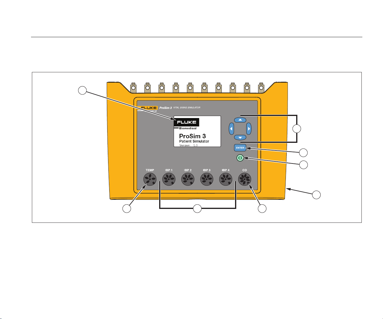
Table 4 is a list of controls and connectors on the Product shown in Figure 1.
1
2
3
4
5
7
Figure 1. Front-Panel Controls and Connectors
68
hal001.eps
5
Page 18

ProSim™ 2/3
Users Manual
Table 4. Front-Panel Controls and Connectors
Item Name Description
Display LCD Display
Navigation buttons Cursor control buttons for navigating menus and lists.
Enter button Sets the highlighted function.
Power button Turns on and off the Product.
DC Power Connector Connector for the AC/DC power supply.
Cardiac Output Connector Connector to the Cardiac input of the patient monitor.
Temperature Connector Connector to the Temperature input of the patient monitor.
Invasive Blood Pressure
Connectors
Four connectors to the Invasive Blood Pressure (IBP) input of the patient monitor.
6
Page 19

Vital Signs Simulator
Product Familiarization
Table 5 is a list of connectors on the top-panel of the Product shown in Figure 2.
1
2
hal006.eps
Figure 2. Top-Panel Connectors
Table 5. Top-Panel Connectors
Item Name Description
ECG Posts Connection posts for ECG leads from the patient monitor.
Mini-Series B Connector For firmware updates and calibration.
7
Page 20

ProSim™ 2/3
Users Manual
Battery Eliminator
The Product can operate on its two 9-Volt batteries or from
mains power. To run on mains power, connect the Product
to the optional AC/DC Power Supply as shown in Figure 3.
How to Turn On the Product
Push on the front panel to turn on the Product. The
power-up screen shows in the display (Figure 4 ).
hal007.bmp
Figure 4. Power-Up Screen
When the self test is complete and no errors are sensed,
the home screen shows in the display (Figure 5).
8
Figure 3. Battery Eliminator Connections
hal022.eps
Page 21

Vital Signs Simulator
Operation
Table 6. Product Functions
ICON Description ICON Description
hal002.eps
Figure 5. Home Screen
Operation
All Product functions are shown in the home screen. See
Figure 5. To set parameters for a function, push the
navigation buttons (, , , ) to move the highlight to a
function icon. Push . Table 6 is a list of Product
functions shown in the home screen.
ECG
RESP
BP
ARRY
PERF
ECG Waveform
Respiration
Blood Pressure
Arrhythmia
Performance Wave
PACE
TEMP
CO
FE/MA
SETUP
Pacemaker
Temperature
Cardiac Output
Fetal/Maternal
Setup
To set a parameter of a function:
1. Push the navigation buttons to move the highlight to a
function. Figure 6 shows the cardiac output icon
highlighted.
Figure 6. Home Screen – Cardiac Function
hal005.bmp
9
Page 22

ProSim™ 2/3
Users Manual
2. Push . The cardiac output screen in Figure 7
shows in the display.
hal003.eps
Figure 7. Cardiac Output Screen
3. To set the injection temperature, push to move the
highlight to the INJ Temp value.
4. Push or to change the value for the highlighted
parameter. The adjusted simulated value changes the
output signal immediately.
All parameter values in the Product are set with this
procedure. For the parameters that cannot be set, the
highlight will not move to the value of that parameter.
There are two procedures to move between Product
functions. When the home screen is not shown in the
display, Prev, Home, and Next show along the bottom of
the display. To move to the home screen, move the
highlight to Home and push . The home screen
shows all the Product functions. See Figure 5.
An alternative to the Home screen is to use the Prev and
Next selections. The software lets you move through the
Product functions sequentially. The function sequence is:
ECG, Respiration, Blood Pressure, Arrhythmias,
Performance Wave, Pacemaker Wave, Temperature,
Cardiac Output, Fetal Maternal, and Setup.
For example, look at the Cardiac Output screen in
Figure 7. When you move the highlight to Prev and push
, the display shows the Temperature screen. When
you highlight Next and push in the Cardiac Output
screen, the display shows the Fetal/Maternal screen.
Cardiac Functions
The cardiac functions of the Product are ECG, Arrhythmia,
Blood Pressure, Pacemaker, Cardiac Output, and
Performance Waves.
ECG Functions
The ECG function of the Product lets you set five
parameters of an ECG waveform: Rate, Amplitude, Patient
Type, ST, and Artifact. Figure 9 shows a typical setup for
an ECG test on a patient monitor.
To set an ECG parameter:
1. In the Home screen, push the navigation buttons to
move the highlight to
2. Push to show the ECG screen in Figure 8 in the
display.
ECG
.
10
Page 23

Vital Signs Simulator
Cardiac Functions
hal004.bmp
Figure 8. ECG Screen
See the Function Navigation and Parameter Selection
section to learn how to set parameter values. See the
detailed specifications for the range of parameter values.
These parameters change the waveform that appears on
the ECG posts along the top of the Product.
11
Page 24

ProSim™ 2/3
Users Manual
Patient
Monitor
ECG
Cable
Figure 9. ECG Test Connections
ProSim 2/3
hal030.eps
12
Page 25

Vital Signs Simulator
Cardiac Functions
Pacemaker Signals
The Product can simulate heart signals with pacemaker
control signals. To set the waveform, amplitude, and width
of the pacemaker signal:
1. In the Home screen, push the navigation buttons to
highlight
PACE
.
2. Push to show the Pacemaker Waves screen in
the display.
3. Use the parameter selection procedure described in
the Operation section to set the parameters of the
pacemaker signal.
See the detailed specifications for the range of parameter
values.
Arrhythmia Function
The Product can simulate heart arrhythmias. To start an
ECG arrhythmia simulation:
1. In the Home screen, push the navigation buttons to
highlight
2. Push to show the Arrhythmias screen in the
display. See Figure 10.
ARRY
.
hal009.bmp
Figure 10. Arrhythmia Screen
The simulated arrhythmias are grouped into four
categories: Supraventricular, Premature, Ventricular,
and Conduction Defect. See the specifications to learn
the arrhythmias in each group.
3. Push or to move the highlight to an arrhythmia
group icon.
4. Push .
5. Use the parameter selection procedure described in
the Operation section to set the arrhythmia.
When the type parameter has been set to an arrhythmia,
the group icon of the group the arrhythmia belongs to has
a thicker border around it.
13
Page 26

ProSim™ 2/3
Users Manual
To stop an arrhythmia simulation:
1. Highlight one of the group icons.
2. Push .
3. Push or until the type value shows Off.
ECG Tests
The Product can source pulse, square, triangle, and sine
waveforms that can be used to verify patient monitors and
other ECG equipment. These waveforms are used in tests
for frequency response, sensitivity, gain drift, internal
calibration, stylus damping, paper speed, linearity, sweep
speed, and more.
The Product also sources an R-wave that is used to verify
that ECG equipment can detect the R-wave part of an
ECG signal.
Note
When the Product is set to source a performance
waveform, respiration and blood pressure
simulations are disabled.
How to Set a Performance Wave Output
To set a performance wave on the ECG terminals:
1. In the Home screen, push the navigation buttons to
highlight
PERF
.
3. Use the parameter selection procedure described in
the Operation section to set the frequency, shape, and
amplitude of the performance waveform.
See the detailed specifications for the range of parameter
values.
R-Wave Detection Test
You can set the Product to source a normal heart ECG
signal and vary the amplitude and width of the R-wave
portion of the waveform. To set the R-wave portion of an
ECG waveform:
1. In the Home screen, push the navigation buttons to
highlight
2. Push to show the Performance Wave screen in
the display.
3. Push the navigation buttons to highlight
4. Push to show the R-Wave Detection screen in
the display.
5. Use the parameter selection procedure described in
the Operation section to set the beats per minute
(bpm), width, and amplitude of the R-wave.
PERF
.
RWDET
.
2. Push to show the Performance Wave screen in
the display.
14
Page 27

Vital Signs Simulator
Cardiac Functions
Blood Pressure Function
The Product simulates dynamic Blood Pressure (BP)
waveforms that synchronize with all normal sinus rhythm
rates and track all simulated arrhythmias. You can set
each of the four BP channels independently. Each channel
simulates a bridge pressure transducer. A respiration
artifact can be injected into each BP channel waveform.
How to Set the BP Sensitivity
The sensitivity of the four BP channels must be set to
match the sensitivity of the patient monitor. To set BP
channel sensitivity:
1. In the Home screen, push the navigation buttons to
highlight
SETUP
.
2. Push to show the Setup screen in the display.
3. Use the parameter selection procedure described in
the Operation section to set the BP Sense parameter.
How to Set Up a BP Channel
To set up one of the four BP channels:
1. In the Home screen, push the navigation buttons to
highlight
2. Push to show the Blood Pressure screen in the
display.
3. Push or to highlight the BP channel you want to
set up.
BP
.
5. Before you start the BP simulation, you must set the
simulated pressure to 0 mmHg. Push the navigation
buttons to highlight
ZERO
.
6. Push . The static pressure parameter is set to
0 mmHg and the dynamic and artifact variables are set
to Off.
7. Zero the patient monitor to set the baseline for future
simulations.
8. Use the parameter selection procedure described in
the Operation section to set the Blood Pressure
channel parameters.
Dynamic BP Waveforms
The Dynamic parameter is used to simulate the various
pressures that are found around the heart and associated
blood vessels. The dynamic waveforms have a normal
sinus rhythm at 80 bpm. Only the systolic and diastolic
pressures change for each dynamic waveform.
All the dynamic waveforms are not available on all four BP
channels. Table 7 is a list of the dynamic BP waveforms
with a check to indicate which BP channel each waveform
can be set on.
Note
See the Swanz-Ganz Procedure section to learn
more on how the do this serial simulation.
4. Push to show the Blood Pressure screen for
the channel in the display.
15
Page 28

ProSim™ 2/3
Users Manual
Table 7. Dynamic BP Waveforms by BP Channel
Dynamic Waveform
Name Pressures
Arterial 120/80 √ √ √
Radial Artery 120/80 √ √ √
Left Ventricle 120/00 √ √ √
Left Atrium 14/4 √ √
Right Atrium 15/10 √ √ √
Right Ventricle 25/00 √ √ √ √
Pulmonary Artery 25/10 √ √ √
Pulmonary Wedge 10/2 √ √ √
BP1 BP2 BP3 BP4
Ganz
In Swanz-
Procedure
16
Page 29

Vital Signs Simulator
Cardiac Functions
How to Add a Respiration Artifact to the BP Waveform
When the dynamic parameter for a blood pressure channel
is set to a value other than off, the Product will let you
move the highlight to the artifact parameter. With the
highlight on the artifact value, push or to toggle the
value between on and off.
Each BP channel has a different range of pressure change
due to the respiration artifact.
Cardiac Output
The Cardiac Output function electronically simulates the
dynamic temperature changes of blood that is cooled by
an injectate.
Note
Cardiac output measurement devices that use the
Fick dye injection, Doppler ultrasonography, and
bioimpedance are not addressed or intended for
this Product.
Cardiac-Output Test Set Up
To simulate cardiac output with the Product, a CI-3
adapter is necessary to connect the monitor to the
Product. The adapter is shown in Figure 11. Note that the
injectate temperature thermistor has to be cut off at the
EUT cable to install the general-purpose connector.
connector is for catheter blood temperature (BT) and is
standard on most monitors.
Note
This 3-pin catheter BT connector is compatible
with the standard Baxter (Edwards) BT catheter
and equivalent catheters available from other
manufacturers such as Viggo-SpectraMed and
Abbott (Sorenson).
The larger 4-pin connector supplies the simulated injectate
temperature. The 10-turn 100 kΩ potentiometer enables
adjustment of the injectate temperature to 0 °C or 24 °C.
The 4-pin IT thermistors connector is not standard on all
monitors. A general function connector that you can
connect to the device under test (DUT) injectate cable is
also available.
Note
A DUT cardiac output cable changed for this test
must not be used in clinical applications.
This module has connections for the cardiac output
measurement under test and simulates the injectate
temperature (IT) thermistors at 0 °C or 24 °C. Of the two
connectors on the CI-3 module/cable, the smaller 3-pin
17
Page 30

ProSim™ 2/3
Users Manual
CI-3 Module/Cable
Blood temperature (BT) connector
Injectate temperature (IT)
thermistor connector
Injectate temperature (IT)
10-turn potentiometer
Figure 11. Cardiac Output Injectate CI-3 Adapter
Assembly of the
General Purpose Connector
Injectate temperature (IT) thermistor connector
PIN
1
2
3
4
Viewed from
the top
of the C1-3
Thermistor
end of cable
INJECTATE THERMISTOR CONNECTION A
NO CONNECTION
INJECTATE THERMISTOR CONNECTION B
NO CONNECTION
1
3
FUNCTION
2
4
Crimp tube
Solder wires to
pins 1 and 3
Pin 3
Pin 1
hal010.eps
For cardiac output simulation, use the supplied CI-3
adapter to connect the Product to the Device Under Test
(DUT). (see Figure 12). If necessary, use the generalpurpose connector.
18
To do a cardiac output test:
1. Connect the patient monitor to the cardiac output
adapter.
2. Connect the adapter to the Product (Figure 12).
Page 31

Vital Signs Simulator
Cardiac Functions
3. Set up the patient monitor to:
• Catheter size: 7 F
• Injectate volume: 10 cc
• Injectate temperature: 0 °C or 24 °C
• Computational constant: 0.542 for 0 °C injectate
or 0.595 for 24 °C injectate
4. In the Home screen of the Product, push the
navigation buttons to highlight
CO
.
5. Push to show the cardiac output screen.
6. Use the parameter selection procedure to set the
cardiac output parameters for the test. See the
detailed specifications to learn the range of each
parameter.
7. Push the navigation buttons to highlight
START
.
8. Push to start the test. The simulation stops
automatically.
To stop the simulation, highlight
STOP
and push .
How to Simulate Injectate Failure and Left-toRight Shunt Fault
The Cardiac Output function can simulate an injectate
failure or left-to-right shunt fault. To set either of these two
failures:
4. Push to start the test.
How to Simulate Output from a Calibrated Pulse Signal
The Product sources a waveform that simulates an
injectate temperature of 0 °C or 24 °C with a step of 1.5 °C
for 1 second as a test for a cardiac-output monitor. To
output a calibration pulse:
1. In the Cardiac Output screen, push or to
highlight the Wave value.
2. Push or until CAL PULSE shows in the display.
3. Push or to highlight
4. Push to start the test.
START
.
1. Push or to highlight the Wave value.
2. Push or until FAULTY INJ or L to R SHUNT
shows in the display.
3. Push the navigation buttons to highlight
START
.
19
Page 32

ProSim™ 2/3
Users Manual
Patient
Monitor
ProSim 2/3
Blood
Temperature
Connection
20
Injectate
Temperature
Connection
Cardiac Output
Adapter
7
0
0
4
6
0
0
5
6
Figure 12. Cardiac Output Connections
hal057.eps
Page 33

Vital Signs Simulator
Cardiac Functions
Fetal/Maternal Function
The Product can simulate fetal and maternal
electrocardiograms (ECG) that occur while in labor.
Pressure waveforms of uterine contractions can also be
simulated.
The fetal/maternal ECG signal is sourced on the ECG
posts of the Product. The maternal signal is a P-QRS-T
wave fixed at 80 bpm with an amplitude that is half the
value of the amplitude parameter. The fetal signal is a
narrow R-wave at full amplitude. The fetal and maternal
signals are combined to make a composite signal.
Simulate Fixed Fetal Heart Rate (FHR)
To set a fixed fetal heart rate:
1. In the Home screen of the Product, push the
navigation buttons to highlight
2. Push to show the Fetal Maternal screen.
3. Use the parameter selection procedure to set the FHR
parameter.
The set FHR value shown in the display is output and
continues on the output until the value is changed.
FE/MA
.
How to Simulate a Periodic FHR with Intrauterine Pressure (IUP)
The Product can simulate intrauterine pressure (IUP) of a
contraction of the uterus in childbirth. The IUP wave is a
bell shaped curve that starts at zero and increases to
90 mmHg and decreases to zero over a 90-second period.
The frequency of contractions can be set to manual, 2, 3
or 5 minutes.
The fetal heart rate starts at 140 bpm and changes with
blood pressure. Fetal heart rate and IUP are shown in the
display.
The Product simulates three preconfigures waveforms for
periodic FHR:
Early deceleration – The fetal heart rate follows the
intrauterine pressure (no lag). FHR starts at 140 bpm,
slows to 100 bpm at the intrauterine pressure peak and
then returns to 140 bpm at the IUP decreases back to
zero.
Late deceleration – The fetal heart rate change starts
when the IUP is at its peak and lags the change in
intrauterine pressure by 45 seconds. FHR starts at
140 bpm, slows to 100 bpm, and then increases back to
140 bpm
Acceleration – The fetal heart rate lags the change in
intrauterine pressure by 30 seconds. FHR starts at
140 bpm, increases to 175 bpm, and then decreases back
to 140 bpm.
21
Page 34

ProSim™ 2/3
Users Manual
To set a periodic FHR with IUP:
1. If the Fetal Maternal screen shows in the display, go to
step 3. If not, go to the Home screen of the Product
and push the navigation buttons to highlight
FE/MA
.
2. Push to show the Fetal Maternal screen.
3. Use the parameter selection procedure to set the FHR,
IUP, and Period parameters
4. Push the navigation buttons to highlight
START
.
5. Push to start the test. If the Period parameter is
set to Manual, the simulation stops automatically after
the IUP wave stops. Each time you push
another IUP wave starts. If not set to Manual, the IUP
wave repeats at the frequency set in the Period
parameter until the simulation is stopped.
To stop the simulation, highlight
STOP
and push .
22
Page 35

Vital Signs Simulator
Cardiac Functions
Fetal Monitor
Intrauterine
Blood Pressure
Input
BP Cable
IBP Channel 4
ProSim 2/3
Fetal ECG
Input
Jumper
Wires
Maternal Thigh
Reference Plate
Figure 13. Fetal/Maternal Connections
Fetal Scalp
Electrode
hal058.eps
23
Page 36

ProSim™ 2/3
Users Manual
Other Functions
The Product also simulates respiration and temperature.
This section contains the procedures to set up the Product
for these two functions.
Respiration Functions
The Respiration function lets you set five parameters of
the respiratory waveform: Rate, Impedance, Baseline
Impedance, Lead selection (left arm or left leg), and
Apnea. To set the respiration waveform:
1. In the Home screen, push the navigation buttons to
move the highlight to
2. Push to show the respiration screen in the
display.
See the Function Navigation and Parameter Selection
section to learn how to set the respiration parameter
values. See the detailed specifications for range of
parameter values. These parameters change the
waveform that appears at the ECG posts along the top of
the Product.
When the Apnea parameter is set to 12, 22, or 32, the
apnea event starts immediately. When the event ends, the
parameter is set to Off. You must set the parameter to 12,
22, or 32 to start another apnea event.
RESP
.
Temperature
Temperatures simulated by the Product are compatible
with Yellow Springs, Inc. (YSI) Series 400 and 700 probes.
The type of cable connected to the temperature jack sets
the type of temperature probe simulated. Connect the
temperature input of the UUT to the Temperature jack as
shown in Figure 14.
To set temperature:
1. In the Home screen, push the navigation buttons to
move the highlight to
2. Push to show the temperature screen in the
display.
See the Function Navigation and Parameter Selection
section to learn how to set the temperature parameter
value. See the detailed specifications for range of
parameter values. These parameters change the
temperature signal at the temperature connector.
TEMP
.
The values set for the baseline and lead parameters when
the Product is turned off, become the power-up default
values.
24
Page 37

Vital Signs Simulator
Other Functions
ProSim 2/3
Temperature
Patient
Monitor
Cable
hal038.eps
Figure 14. Temperature Simulation Connections
25
Page 38

ProSim™ 2/3
Users Manual
Remote Operation
The Product has a USB device port that lets you control
the Product remotely with a set of commands. To control
the Product from a PC, connect the USB to a USB port on
the PC. The PC must have the Windows XP, Vista, or
USB Port
Windows 7 or later operating system to control the
Product.
To operate the Product from the PC, connect it to the PC
as shown in Figure 15.
ProSim 2/3
Mini Series
B Connector
26
Figure 15. Remote Operation Connections
hal060.eps
Page 39

Vital Signs Simulator
Remote Operation
When connected to a PC with a Windows operating
system, the Product will communicate through a PC COM
port. Make sure the COM port parameters are set to:
• 9600 Baud
• No Parity
• 8 data bits
• 1 stop bit
• Hardware handshake set to off
Remote Commands
A remote command is made up of alphanumeric
characters. The first character of a command must be
alphabetic. The alphabetic characters can be upper or
lower case.
• Special characters are:
• Carriage return (CR)
• Line feed (LF)
• Space (SP)
• Backspace (BS)
• Escape (ESC)
The Product will do a command when it receives a
carriage return and/or line feed. Alphabetic characters are
not case sensitive. When you type in a command, the
backspace deletes the last recorded character and the
escape key discards the complete command. When a
command is complete, the Product sends a response that
ends with a carriage return and line feed to the PC. Unless
other data is sent back from the Product, the response is
“OK” if the command is accepted by the Product. When a
command is not accepted by the Product, an error code
shown in Table 8 is sent to the PC.
Table 8. Error Codes
Error Code Description
ERR=00 No commands allowed at this time
ERR=01 Unknown command
ERR=02 Illegal command
ERR=03 Illegal parameter
ERR=04 Data corrupted
ERR=05 Unknown error
ERR=06 Option not installed
ERR=07 Incorrect password
While the Product is operated from the front panel (local
mode) the remote interface will not respond to a command
until the command REMOTE is sent to the Product through
the USB port.
27
Page 40

ProSim™ 2/3
Users Manual
General Commands
Table 9 is list of the modes and their description.
Table 9. Product Control States and Modes
Mode Type Description
LOCAL Local Local control
RMAIN Main Main remote control
DIAG Sub Diagnostic tests remote sub-mode
CAL Sub Calibration remote sub-mode
Table 10 is a list of general commands that set the control
states and modes of the Product. The table shows in
which mode the command is recognized and the response
the Product will send to the PC when the command is
completed.
Table 10. General Commands
Command
REMOTE LOCAL RMAIN Go to remote control
LOCAL RMAIN LOCAL Go to local control
QMODE All
Legal
Mode
modes
Returns Description
See
Table 10
Query the mode
Function Commands
The function commands are grouped by the function they
support.
ECG Functions
Tables 11 and 12 are lists of commands that control the
ECG functions of the Product. These are Normal-sinus
ECG, ECG amplitude, adult/pediatric, ST elevation, ECG
artifact simulation, pacemaker waveform, pacemaker
amplitude, and pacemaker width.
Table 11. ECG Function Commands
Action Command
Normal Sinus
30 bpm NSR30
40 bpm NSR40
45 bpm NSR45
60 bpm NSR60
80 bpm NSR80
90 bpm NSR90
100 bpm NSR100
28
Page 41

Vital Signs Simulator
Remote Operation
Table 11. ECG Function Commands (cont.)
Action Command
Normal Sinus (cont.)
120 bpm NSR120
140 bpm NSR140
160 bpm NSR160
180 bpm NSR180
200 bpm NSR200
220 bpm NSR220
240 bpm NSR240
260 bpm NSR260
280 bpm NSR280
300 bpm NSR300
Amplitude
[1]
0.05 mV NAS0.05
0.10 mV NAS0.10
0.15 mV NAS0.15
0.20 mV NAS0.20
0.35 mV NAS0.35
0.40 mV NAS0.40
0.45 mV NAS0.45
0.50 mV NAS0.50
1.00 mV NAS1.00
1.50 mV NAS1.50
2.00 mV NAS2.00
2.50 mV NAS2.50
3.00 mV NAS3.00
3.50 mV NAS3.50
4.00 mV NAS4.00
4.50 mV NAS4.50
5.00 mV NAS5.00
5.50 mV NAS5.50
Adult/Pediatric
[1]
Adult ADULT
Pediatric PEDS
0.25 mV NAS0.25
0.30 mV NAS0.30
29
Page 42

ProSim™ 2/3
Users Manual
Table 11. ECG Function Commands (cont.)
Action Command
ST Elevation
[1]
-0.8 mV STD-0.8
-0.7 mV STD-0.7
-0.6 mV STD-0.6
-0.5 mV STD-0.5
-0.4 mV STD-0.4
-0.3 mV STD-0.3
-0.2 mV STD-0.2
-0.1 mV STD-0.1
-0.05 mV STD-0.05
0 mV STD0
+0.05 mV STD+0.05
+0.1 mV STD+0.1
+0.2 mV STD+0.2
+0.3 mV STD+0.3
+0.4 mV STD+0.4
+0.5 mV STD+0.5
+0.6 mV STD+0.6
+0.7 mV STD+0.7
+0.8 mV STD+0.8
Artifact Simulation
[1]
Off EAOFF
50 Hz EA50
60 Hz EA60
Muscle EAMSC
Wandering EAWNDR
Respiration EARESP
1. Set the ECG rate before you set amplitude, ST elevation, and artifact.
Table 12. Pacemaker Waveform Commands
Action Command
Waveforms
Atrial Pacer ATR
Asynchronous pacer ASN
Demand frequent sinus DFS
AV sequential AVS
Noncapture NCA
Nonfunction NFU
30
Page 43

Vital Signs Simulator
Remote Operation
Table 12. Pacemaker Waveform Commands (cont.)
Action Command
Amplitude
[1]
1 mV PA1
2 mV PA2
5 mV PA5
10 mV PA10
Width
[1]
0.1 mV PA0.1
0.5 mV PA0.5
1.0 mV PA1.0
1.5 mV PA1.5
2 mV PA2.0
1. Set the Pacemaker waveform before you set amplitude and width.
Arrhythmia Functions
Table 13 is a list of the commands to simulate arrhythmias.
These waveforms are grouped by supraventricular
arrhythmia, premature arrhythmia, ventricular arrhythmia,
and conduction defect.
Table 13. Arrhythmia Function Commands
Action Command
Supraventricular
Atrial fibrillation, coarse AF1
Atrial fibrillation, fine AF2
Atrial flutter AFL
Sinus arrhythmia SINA
Missed beat MB80
Atrial tachycardia ATC
Paroxysmal atrial tachycardia PAT
Nodal rhythm NOD
Supraventricular tachycardia SVT
Premature
Premature atrial contraction PAC
Premature nodal contraction PNC
Premature vent contraction left
(PVC1), standard
PVC1S
31
Page 44

ProSim™ 2/3
Users Manual
Table 13. Arrhythmia Function Commands (cont.)
Action Command
Premature (cont.)
Premature vent contraction left
(PVC1), early
Premature vent contraction left
(PVC1), R on T
Premature vent contraction right
(PVC1), early
Premature vent contraction right
(PVC1), early
Premature vent contraction right
(PVC1), R on T
Multifocal PVCs MF
Ventricular
PVCs 6 per minute PVC6
PVCs 12 per minute PVC12
PVCs 24 per minute PVC24
PVC1E
PVC1R
PVC2S
PVC2E
PVC2R
5 PVCs RUN5
11 PVCs RUN11
Ventricular tachycardia VTC
Ventricular fibrillation, coarse VFB1
Ventricular fibrillation, fine VFB2
Asystole ASY
Conduction Defect
First-degree block 1DB
Second-degree block 2DB
Third-degree block 3DB
Right-bundle branch block RBB
Left-bundle branch block LBB
ECG Test Functions
Table 14 is a list of ECG test function commands. These
commands are grouped by performance waveforms,
performance wave amplitude, R-wave rate, R-wave width,
and R-wave amplitude.
Frequency multifocal PVCs FMF
Begeminy BIG
Trigeminy TRG
Pair of PVCs PAIR
32
Page 45

Vital Signs Simulator
Remote Operation
Table 14. ECG Test Commands
Action Command
Performance Waves
2 Hz square wave SQU2
0.125 Hz square wave SQU.125
2 Hz triangle wave TRI2
2.5 Hz triangle wave TRI2.5
30 bpm pulse wave PUL30
60 bpm pulse wave PUL60
0.5 Hz sine wave SIN0.5
5 Hz sine wave SIN5
10 Hz sine wave SIN10
40 Hz sine wave SIN40
50 Hz sine wave SIN50
60 Hz sine wave SIN60
100 Hz sine wave SIN100
Amplitude
0.20 mV PFA0.20
0.25 mV PFA0.25
0.30 mV PFA0.30
0.35 mV PFA0.35
0.40 mV PFA0.40
0.45 mV PFA0.45
0.50 mV PFA0.50
1.00 mV PFA1.00
1.50 mV PFA1.50
2.00 mV PFA2.00
2.50 mV PFA2.50
3.00 mV PFA3.00
3.50 mV PFA3.50
4.00 mV PFA4.00
4.50 mV PFA4.50
5.00 mV PFA5.00
5.50 mV PFA5.50
0.05 mV PFA0.05
0.10 mV PFA0.10
0.15 mV PFA0.15
33
Page 46

ProSim™ 2/3
Users Manual
Table 14. ECG Test Commands (cont.)
Action Command
R-Wave Rate
R-wave at 30 bpm RWR30
R-wave at 60 bpm RWR60
R-wave at 80 bpm RWR80
R-wave at 120 bpm RWR120
R-wave at 200 bpm RWR200
R-wave at 250 bpm RWR250
R-Wave Width
R-Wave width at 8 ms RWW8
R-Wave width at 10 ms RWW10
R-Wave width at 12 ms RWW12
R-Wave width at 20 ms RWW20
R-Wave width at 30 ms RWW30
R-Wave width at 40 ms RWW40
R-Wave width at 50 ms RWW50
R-Wave width at 60 ms RWW60
R-Wave width at 70 ms RWW70
R-Wave width at 80 ms RWW80
R-Wave width at 90 ms RWW90
R-Wave width at 100 ms RWW100
R-Wave width at 110 ms RWW110
R-Wave width at 120 ms RWW120
R-Wave width at 130 ms RWW130
R-Wave width at 140 ms RWW140
R-Wave width at 150 ms RWW150
R-Wave width at 160 ms RWW160
R-Wave width at 170 ms RWW170
R-Wave width at 180 ms RWW180
R-Wave width at 190 ms RWW190
R-Wave width at 200 ms RWW200
R-Wave Amplitude
0.05 mV RWA0.05
0.10 mV RWA0.10
0.15 mV RWA0.15
0.20 mV RWA0.20
0.25 mV RWA0.25
0.30 mV RWA0.30
0.35 mV RWA0.35
34
Page 47

Vital Signs Simulator
Remote Operation
Table 14. ECG Test Commands (cont.)
Action Command
R-Wave Amplitude (cont.)
0.40 mV RWA0.40
0.45 mV RWA0.45
0.50 mV RWA0.50
1.00 mV RWA1.00
1.50 mV RWA1.50
2.00 mV RWA2.00
2.50 mV RWA2.50
3.00 mV RWA3.00
3.50 mV RWA3.50
4.00 mV RWA4.00
4.50 mV RWA4.50
5.00 mV RWA5.00
5.50 mV RWA5.50
Table 15. Respiration Function Commands
Action Command
Lead
Lead LA RLLA
Lead LL RLLL
Baseline
500 Ω RB500
1000 Ω RB1000
1500 Ω RB1500
2000 Ω RB2000
Rate
0 BrPM RR0
15 BrPM RR15
20 BrPM RR20
30 BrPM RR30
40 BrPM RR40
Respiration Function Commands
Table 15 is a list of respiration function commands. These
commands are grouped by respiration lead, respiration
baseline (impedance), respiration rate, respiration
amplitude, and apena simulation.
60 BrPM RR60
80 BrPM RR80
100 BrPM RR100
120 BrPM RR120
35
Page 48

ProSim™ 2/3
Users Manual
Table 15. Respiration Function Commands (cont.)
Action Command
Amplitude
0.2 Ω RO0.5
0.5 Ω RO0.5
1.0 Ω RO1.0
3.0 Ω RO3.0
Apena Simulation
12 seconds A12
22 seconds A22
32 seconds A32
Continuously AON
Apnea off AOFF
Blood Pressure Function Commands
Table 16 is a list of blood pressure function commands.
These commands are grouped by static pressure, dynamic
pressure, and respiration artifact.
36
Page 49

Vital Signs Simulator
Remote Operation
Table 16. Blood Pressure Function Commands
Action
Channel 1 Channel 2 Channel 3 Channel 4
BP sensitivity to 5 μV/V/mmHg BPSNS5
BP sensitivity to 40 μV/V/mmHg BPSNS40
Zero each channel P1S0 P2S0 P3S0 P4S0
Zero all channels ZALL
Static Pressure Levels
-5 mmHg static NA NA P3S-5 P4S-5
-10 mmHg static P1S-10 P2S-10 NA NA
20 mmHg static NA NA P3S20 P4S20
40 mmHg static NA NA P3S40 P4S40
50 mmHg static NA P2S50 NA NA
60 mmHg static NA NA P3S60 P4S60
80 mmHg static P1S80 NA P3S80 P4S80
100 mmHg static NA P2S100 P3S100 P4S100
150 mmHg static NA P2S150 NA NA
Command
160 mmHg static P1S160 NA NA NA
200 mmHg static NA P2S200 NA NA
37
Page 50

ProSim™ 2/3
Users Manual
Table 16. Blood Pressure Function Commands (cont.)
Action
Channel 1 Channel 2 Channel 3 Channel 4
Static Pressure Levels (cont.)
240 mmHg static P1S240 P2S240 NA NA
320 mmHg static P1S320 NA NA NA
400 mmHg static P1S400 NA NA NA
Dynamic Waveforms
Arterial at 120/80 P1ART P2ART P3ART NA
Radial at 120/80 P1RART P2RART P3RART NA
Left vent at 120/0 P1LV P2LV P3LV NA
Right vent at 25/0 P1RV P2RV P3RV P4RV
Pulmonary at 25/10 NA P2PA P3PA P4PA
Pulmonary at 10/2 NA P2W P3W P4W
Left atrium at 14/4 NA P2LA P3LA NA
Right atrium CVP at 15/10 NA P2CVP P3CVP P4CVP
Command
38
Page 51

Vital Signs Simulator
Remote Operation
Table 16. Blood Pressure Function Commands (cont.)
Action
Dynamic Waveforms (cont.)
Start auto NA NA NA STSGAUTO
Start manual NA NA NA STSG
Insert (manual) NA NA NA INS
Inflate (manual) NA NA NA INF
Swan-Ganz
Deflate (manual) NA NA NA DEF
Pull back (manual) NA NA NA PLBK
Respiration Artifact
Artifact on P1AOFF P2AOFF P3AOFF P4AOFF
Artifact off P1AON P2AON P3AON P4AON
Channel 1 Channel 1 Channel 1 Channel 1
Command
39
Page 52

ProSim™ 2/3
Users Manual
Other Function Commands
Table 17 is a list of commands for other Product functions.
The other functions are temperature, cardiac-output
wave/injectate, fetal heart rate, intrauterine-pressure wave,
intrauterine-pressure period, and beeper.
Table 17. Other Function Commands
Action Command
Temperature
0 °C T0
24 °C T24
37 °C T37
40 °C T40
Cardiac-Output Wave/Injectate
2.5 l/min COW2.5
5.0 l/min COW5.0
10.0 l/min COW10.0
Faulty injectate COWFLT
Injectate to 24 °C COI24
Fetal Heart Rate
60 bpm F60
90 bpm F90
120 bpm F120
140 bpm F140
150 bpm F150
210 bpm F210
240 bpm F240
Intrauterine pressure
Once IUP1
2 minute period IUP2M
3 minute period IUP3M
5 minute period IUP5M
Left/right shunt COWLRS
Cal pulse COWCAL
Stop COSTOP
Injectate to 0 °C COI0
40
Page 53

Vital Signs Simulator
Maintenance
Maintenance
Warning
To prevent possible electrical shock, fire, or
personal injury:
• Have an approved technician repair the
Product.
• Use only specified replacement parts.
• Remove the input signals before you clean
the Product.
• Batteries contain hazardous chemicals that
can cause burns or explode. If exposure to
chemicals occurs, clean with water and get
medical aid.
• Do not put battery cells and battery packs
near heat or fire. Do not put in sunlight.
• Do not disassemble the battery.
• Remove batteries to prevent battery
leakage and damage to the Product if it is
not used for an extended period.
• Do not short the battery terminals together.
• Repair the Product before use if the battery
leaks.
• Be sure that the battery polarity is correct
to prevent battery leakage.
• Do not keep cells or batteries in a
container where the terminals can be
shorted.
• Do not disassemble or crush battery cells
and battery packs.
General Maintenance
Clean the case with a damp cloth and weak detergent. Do
not use solvent or cleaners with abrasives.
Warning
For safe operation and maintenance of the
Product:
• Do not put fluid on the Product surface.
Fluid leakage into the electrical circuitry
can cause the Product to fail.
• Do not use spray cleaners on the Product.
This can push fluid into the Product and
cause electronic component damage.
For safe operation and maintenance of the
Product:
• Keep cells and battery packs clean and
dry. Clean dirty connectors with a dry,
clean cloth.
41
Page 54

ProSim™ 2/3
Users Manual
Battery Replacement
Warning
To prevent possible electrical shock, fire, or
personal injury:
• Remove batteries to prevent battery
leakage and damage to the Product if it is
not used for an extended period.
• Be sure that the battery polarity is correct
to prevent battery leakage.
• Batteries contain hazardous chemicals that
can cause burns or explode. If exposure to
chemicals occurs, clean with water and get
medical aid.
When the charge in the batteries becomes low, a warning
will show in the display. Replace the batteries immediately.
To replace the batteries:
1. Turn off the Product and remove all test leads.
hal008.eps
Figure 16. Battery Replacement
2. Slide the battery door off on the rear of the Product.
See Figure 16.
3. Remove the two 9-volt batteries and replace them with
new ones. Use the correct battery orientation.
4. Install the battery door.
42
Page 55

Vital Signs Simulator
General Specifications
General Specifications
Power ......................................................................... Two 9-V alkaline batteries (IEC 6LR61, NEDA 1604A). Optional battery eliminator: 15 Vdc, 1.5 mA
Battery Life ................................................................ 8 hours minimum
Display ....................................................................... LCD Greyscale Display
Size ............................................................................. 14.0 cm x 20.6 cm x 4.5 cm (5.5 in x 8.2 in x 1.8 in)
Weight ........................................................................ 0.47 kg (1 lb 4 oz)
Temperature
Storage ................................................................ -25 °C to +50 °C (-13 °F to +122 °F)
Operation ............................................................. 10 °C to 40 °C (50 °F to 104 °F)
Humidity .................................................................... 10 % to 80 % non-condensing
Altitude ...................................................................... 2000 m (6,562 ft)
Safety ......................................................................... IEC 61010-1, Pollution degree 2
Electromagnetic Environment ................................. IEC 61326-1, Portable
EMC ............................................................................ Applies to use in Korea only. Class A equipment (Industrial Broadcasting & Communication Equipment)
[1]
[1] This Product meets requirements for industrial (Class A) electromagnetic wave equipment and the
seller or user should take notice of it. This equipment is intended for use in business environments and
is not to be used in homes.
Detailed Specifications
ECG Waveform
ECG Reference.......................................................... The ECG amplitudes specified are for Lead II, from the baseline to the peak of the R wave. All other
Lead I .................................................................. 70 %
Lead II ................................................................. 100 %
Lead III ................................................................ 30 %
Lead V1 ............................................................... 24 %
Lead V2 ............................................................... 48 %
Lead V3 ............................................................... 100 %
Lead V4 ............................................................... 120 %
Lead V5 ............................................................... 112 %
leads are proportional in percentage per:
43
Page 56

ProSim™ 2/3
Users Manual
Lead V6 .............................................................. 80 %
Normal Sinus Rhythm ............................................. 12-lead configuration with independent outputs referenced to right leg (RL). Output to 10 Universal ECG
Amplitude ................................................................. 0.05 mV to 0.45 mV (0.05 mV steps), 0.5 mV to 5.5 mV (0.5 mV steps)
Amplitude Accuracy ................................................ ±2 % of setting Lead II. All other leads ±5 %
ECG Rate .................................................................. 30, 40, 45, 60, 80, 90, 100, 120, 140, 160, 180, 200, 220, 240, 260, 280, and 300 BPM
Rate Accuracy .......................................................... ±1 % of setting
ECG Waveform Selection ........................................ Adult (80 ms) or pediatric (40 ms) QRS duration
Artifact (Superimposed) .......................................... 50 and 60 Hz, muscle, baseline wander, respiration
ST-Segment Elevation ............................................. Adult mode only. -0.8 mV to +0.8 mV (0.1 mV steps) Additional steps: +0.05 mV and -0.05 mV
Power-On Default ..................................................... 80 BPM, 1.0 mV, adult QRS, ST-segment elevation of 0 mV, and a P-R interval of 0.16 seconds
Jacks, color-coded to AHA and IEC Standards.
Pacemaker Waveform
Pacer-Pulse Amplitude ............................................ 0 (off), 1, 2, 5, 10 mV ±10 % for lead II (reference lead) with other leads proportional as for performance
Pacer-Pulse Width ................................................... 0.1, 0.5, 1.0, 1.5, 2.0 ms ±5 %
Pacing Rate .............................................................. 75 BPM
Paced Arrhythmias .................................................. Atrial 80 BPM
Power-On Default ..................................................... Off
waves.
Asynchronous 75 BPM
Demand with frequent sinus beats
Demand with occasional sinus beats
Atrio-Ventricular sequential
Noncapture (one time)
Nonfunction
Arrhythmia
Baseline NSR ........................................................... 80 BPM
PVC Focus ................................................................ Left focus, standard timing (except where specified)
Supraventricular Arrhythmia .................................. Atrial fibrillation (coarse or fine), atrial flutter, sinus arrhythmia, missed beat (one time), atrial tachycardia,
Premature Arrhythmia ............................................. (All one-time events) Premature atrial contraction (PAC), premature nodal contraction (PNC), PVC1 left
paroxysmal atrial tachycardia, nodal rhythm, and supraventricular tachycardia
ventricular, PVC1 left ventricular – early, PVC1 left ventricular – R on T, PVC2 right ventricular, PVC2
right ventricular – early, PVC2 right ventricular – R on T, and multifocal PVCs
44
Page 57

Vital Signs Simulator
Detailed Specifications
Ventricular Arrhythmia ............................................. PVCs (6, 12, or 24 per minute), frequent multifocal PVCs, bigeminy, trigeminy, multiple PVCs (one-time
Conduction Defect .................................................... First-, second-, or third-degree AV block and right- or left-bundle-branch block
Power-On Default...................................................... None (off)
run of 2, 5, or 11 PVCs), ventricular tachycardia, ventricular fibrillation (coarse or fine), and asystole
ECG-Performance-Tests
Amplitude .................................................................. 0.05 mV to 0.45 mV (0.05 mV steps)
Pulse Wave ................................................................ 30 BPM, 60 BPM, with 60 ms pulse width
Square Wave ............................................................. 2.0, 0.125 Hz
Triangle Wave ........................................................... 2.0, 2.5 Hz
Sine Wave .................................................................. 0.5, 5, 10, 40, 50, 60, 100 Hz
R-wave-Detection Waveform ................................... Haver-Triangle
R-wave Rate .............................................................. 30, 60, 80, 120, 200, and 250 BPM
R-wave Width ............................................................ 20 ms to 200 ms (10 ms steps)
Rate Accuracy ........................................................... ±1 %
Amplitude Accuracy ................................................. ±2 %, Lead II (Exception: ±5 % for R waves ≤20 ms)
Power-On Default ..................................................... None (off)
0.5 mV to 5.5 mV (0.5 mV steps)
Additional Steps: 8, 10, and 12 ms
Respiration
Rate ............................................................................ 0 (OFF), 15, 20, 30, 40, 60, 80, 100, 120 BrPM
Impedance Variations (Δ Ω) ..................................... 0.2, 0.5, 1, or 3 Ω peak-to-peak variation of lead impedance
Delta Accuracy .......................................................... ±10 %
Baseline ..................................................................... 500, 1000, 1500, 2000 Ω, Leads I, II, III
Accuracy Baseline .................................................... ±5 %
Respiration Lead ....................................................... LA or LL
Apnea Selection ........................................................ OFF, 12, 22, or 32 seconds (one-time events), or continuous (Apnea ON = respiration OFF)
Power-On Default...................................................... 20 BrPM, delta 1.0 Ω, 1000-Ω baseline
Blood Pressure
Input/output Impedance ........................................... 300 Ω ±10 %
Exciter Input Range .................................................. 2.0 V to 16.0 V rms
45
Page 58

ProSim™ 2/3
Users Manual
Exciter-Input Frequency Range .............................. DC to 5000 Hz
Transducer Sensitivity ............................................ 5 μV/V/mmHg or 40 μV/V/mmHg
Pressure Accuracy .................................................. ±(2 % of setting + 2 mmHg) (Valid for dc excitation only)
Static Levels, Channel 1 .......................................... -10, 0, 80, 160, 240, 320, 400 mmHg
Static Levels, Channel 2 .......................................... -10, 0, 50, 100, 150, 200, 240 mmHg
Static Levels, Channel 3 (ProSim 3 only) .............. -5, 0, 20, 40, 60, 80, 100 mmHg
Static Levels, Channel 4 (ProSim 3 only) .............. -5, 0, 20, 40, 60, 80, 100 mmHg
Dynamic Waveforms, Channel 1 ............................ Arterial: 120/80
Dynamic Waveforms, Channel 2 ............................ Arterial: 120/80
Dynamic Waveforms, Channel 3 (ProSim 3 only) . Arterial: 120/80
Dynamic Waveforms, Channel 4 (ProSim 3 only) . Swan-Ganz sequence:
Respiration Artifact ................................................. BP delta changes from 3 mmHg to 16 mmHg
Output Connector .................................................... DIN 5-Pin
Power-On Default ..................................................... 0 mmHg
Radial artery: 120/80
Left ventricle: 120/00
Right ventricle: 25/00
Radial artery: 120/80
Left ventricle: 120/00
Right atrium (central venous or CVP): 15/10
Right ventricle: 25/00
Pulmonary artery: 25/10
Pulmonary-artery wedge: 10/2
Left atrium: 14/4
Radial artery: 120/80
Left ventricle: 120/00
Right atrium (central venous or CVP): 15/10
Right ventricle: 25/00
Pulmonary artery: 25/10
Pulmonary-artery wedge: 10/2
Left atrium: 14/4
Right atrium (CVP)
Right ventricle RV)
Pulmonary artery (PA)
Pulmonary-artery wedge (PAW)
46
Page 59

Vital Signs Simulator
Detailed Specifications
Temperature
Temperature .............................................................. 0 °C (32 °F), 24 °C (75.2 °F), 37 °C (98.6 °F), and 40 °C (104 °F)
Accuracy .................................................................... ±0.1 °C
Compatibility ............................................................. Yellow Springs, Inc. (YSI) Series 400 and 700
Output Connector ..................................................... DIN 4-pin
Power-On Default...................................................... 0 °C (42 °F)
Cardiac Output (ProSim 3 Only)
Catheter Type ............................................................ Baxter Edwards, 93a-131-7f
Calibration Coefficient ............................................. 0.542 (0 °C injectate), 0.595 (24 °C injectate)
Blood Temperature ................................................... 37 °C (98.6 °F) ±2 %
Injectate Volume ....................................................... 10 cc
Injectate Temperature .............................................. 0 °C or 24 °C ±2 % value
Cardiac Output .......................................................... 2.5, 5, 10 liters per minute ±5 %
Faulty-Injectate Curve .............................................. Waveform for simulation available
Left-to-Right-Shunt Curve ........................................ Waveform for simulation available
Calibrated Pulse........................................................ 1.5 ° for 1 second (37 ° to 35.5 °)
Output Connector ..................................................... DIN 7-Pin
Power-On Default ..................................................... 2.5 liters per minute, 0 °C injectate
Fetal / Maternal-ECG (ProSim 3 Only)
Fetal Heart Rate (Fixed)............................................ 60, 90, 120, 140, 150, 210, and 240 BPM
Fetal Heart Rate (IUP): .............................................. 140 BPM at beginning, then varies with pressure
Intrauterine-Pressure Waveforms ........................... Early deceleration, late deceleration, and uniform acceleration
Wave Duration ........................................................... 90 seconds, bell-shaped pressure curve, from 0 mmHg to 90 mmHg and returning to 0 mmHg
IUP Period .................................................................. 2, 3, or 5 minutes, and manual
Power-On Default...................................................... FHR 120 BPM, early deceleration, manual
47
Page 60

ProSim™ 2/3
Users Manual
Computer Setup
USB Device Upstream Port ..................................... Mini-B connector for control by a computer
Baud Rate ................................................................. 9600
Parity ......................................................................... None
Stop Bits ................................................................... 1
Data Bits ................................................................... 8
48
 Loading...