

Page 1

PQ400
PQ Window
Voltage/Current Measurement Feed-Through
Device for Electrical Enclosures
Instructions
PQ Window (the Product) is an accessory that mounts to the
flat surface of a Type 12 electrical enclosure (derate to Type 1
during measurements). When the Product is installed and signal
feeds connected, you can safely perform voltage and current
measurements from outside the enclosure.
Standard 4 mm safety sockets on the front provides access
to the three phases (A/L1, B/L2, C/L3), Neutral N, and Earth/
Ground for voltage measurements. The voltage outputs
support instruments that are powered from the measurement
line with a maximum power of 100 VA.
The Product supports current measurement with Fluke
intelligent current sensors (iFlex1500-12, iFlex 3000-24,
i40S-EL and i400S-EL). Go to www.fluke.com
compatible accessories.
The 354x FC, 173x Power, and 174x Power Quality Loggers
automatically read the sensor information, such as, the type,
serial number, scale factor, and phase angle compensation.
Use the optional adapter kit to connect instruments and
current sensors that have BNC connectors.
for a full list of
PN 4954885 October 2018 Rev. 1, 2/19
©2018-2019 Fluke Corporation. All rights reserved.
Specifications are subject to change without notification.
All product names are trademarks of their respective companies.
Fluke Corporation
P.O. Box 9090
Everett, WA 98206-9090
U.S.A.
Fluke Europe B.V.
P.O. Box 1186
5602 BD Eindhoven
The Netherlands
ООО «Флюк СИАЙЭС»
125167, г. Москва,
Ленинградский проспект дом 37,
корпус 9, подъезд 4, 1 этаж
Page 2

To contact Fluke, call one of the following telephone numbers:
• Technical Support USA: 1-800-44-FLUKE
(1-800-443-5853)
• Calibration/Repair USA:
• 1-888-99-FLUKE (1-888-993-5853)
• Canada: 1-800-36-FLUKE (1-800-363-5853)
• Europe: +31 402-675-200
• Japan: +81-3-6714-3114
• Singapore: +65-6799-5566
• China: +86-400-921-0835
• Brazil: +55-11-3530-8901
• Anywhere in the world: +1-425-446-5500
Or, visit Fluke's website at www.fluke.com
To register your product, visit http://register.fluke.com
To view, print, or download the latest manual supplement,
visit http://us.fluke.com/usen/support/manuals
A Warning identifies conditions and procedures that are
dangerous to the user.
XW Warning
To prevent possible electrical shock, fire, or
personal injury:
• Read all safety information before you use
the Product.
• Carefully read all instructions.
• Do not alter the Product and use only as
specified, or the protection supplied by the
Product can be compromised.
• Do not touch voltages >30 V ac rms,
42 V ac peak, or 60 V dc.
• Do not use the Product around explosive
gas, vapor, or in damp or wet
environments.
.
.
.
Page 3

• Only install the Product to the specified
measurement category, voltage, or
amperage ratings.
• Do not exceed the Measurement Category
(CAT) rating of the lowest rated individual
component of a Product, probe, or
accessory.
• Do not use the Product if it is damaged.
• De-energize the voltage inputs before you
open the feed-through box.
• Comply with local and national safety codes.
Use personal protective equipment
(approved rubber gloves, face protection,
and flame-resistant clothes) to prevent
shock and arc blast injury where hazardous
live conductors are exposed.
• Use a circuit breaker rated for the wire gauge
used on the voltage inputs to the Product.
• Make sure that the sealing areas are clean
before you close the cover.
• Use only the replacement fuses specified by
the manual.
• Only for installation on bonded metal
enclosures that provide a protective earth
connection.
Page 4

Symbols
Symbol Description
W
X
P
)
Type 1
Type 12
~
WARNING. RISK OF DANGER.
WARNING. HAZARDOUS VOLTAGE. Risk of
electric shock.
Consult user documentation.
Measurement Category III is applicable to test and
measuring circuits connected to the distribution
part of the building’s low-voltage MAINS
installation.
Measurement Category IV is applicable to test and
measuring circuits connected at the source of the
building’s low-voltage MAINS installation.
Conforms to European Union directives.
Certified by CSA Group to North American safety
standards.
Conforms to relevant Australian EMC standards.
NEMA 250 Enclosure Type. Enclosure suitable for
indoor use under normal atmospheric conditions.
Protection against access to hazardous parts and
ingress of solid foreign objects (falling dirt).
NEMA 250 Enclosure Type. Enclosure suitable for
indoor use. Protection against dust, dripping, and
light splashing of non-corrosive liquids.
This product complies with the WEEE Directive
marking requirements. The affixed label indicates
that you must not discard this electrical/electronic
product in domestic household waste. Product
Category: With reference to the equipment types in
the WEEE Directive Annex I, this product is
classed as category 9 "Monitoring and Control
Instrumentation" product. Do not dispose of this
product as unsorted municipal waste.
Page 5
Before You Start
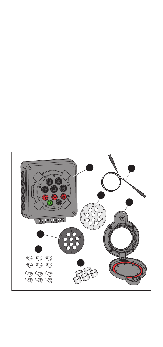
Unpack the Product when it arrives. See Figure 1. Identify and
make sure all the parts are in the shipment:
PQ Window Feed-Through Box
Top Plate (installed on )
PQ Window Frame with Cover
Top Plate Decal Set
Screws: x6 flathead (installed) / x6 panhead
Cable Marker Set
Current Test Leads (x4)
Note
A single current test lead is available as an
optional accessory for Loggers that support five
current channels.
Cable Tie Set (not shown)
Instruction Sheet (not shown)
4
5
6
Figure 1. PQ Window Parts
1
2
7
3
Page 6

Figure 2 shows the tools required for site preparation and
1
2
3
4
5
6
7
installation:
Hole punch
Punch/Die 114.3 mm (4.5 in) for example, Greenlee
742BB
Twist drill
Center punch
Calibrated torque driver
File
Degreasing supplies (for example, Isopropyl alcohol and
soft cloth)
Hex key bit 3/16 in (not shown)
Pozidriv screwdriver #1 (not shown)
Figure 2. Tool Requirements
Accessories
• Fuse, 2A
• I17XX-BNC-M2M, Fluke-17XX 4-pin Male to BNC Male
Cable 2 m (1x)
• I17XX-BNC-M2F, Fluke-17XX 4-pin Male to BNC
Female Cable 0.1 m (1x)
• I17XX-FLEX2M-M2M4P, Fluke-17XX iFlex Male-Male
Cable 2 m (4x)
• I17XX-FLEX2M-M2M1P, Fluke-17XX iFlex Male-Male
Cable 2 m (1x)
• Fluke-PQ-MARKER, cable marker set 3PH+N+PE
Page 7

Site Preparation
XW Warning
To prevent possible electrical shock, fire, or
personal injury, de-energize and lock-out the
electrical enclosure (refer to local standards)
before you install the Product.
These instructions use the Greenlee 742BB punch/die. For
other punch/die models, see the instructions provided with
the tool. See Figure 3 to prepare the installation site:
1. Mark a pilot hole with the center punch.
2. Drill a 6 mm (0.2 in) pilot hole with the twist drill and use
a step drill bit to enlarge the 6 mm (0.2 in) pilot hole to
20 mm (0.8 in).
Or, drill a 10 mm (0.4 in) pilot hole and then enlarge the
hole to 22.5 mm (0.875 in) with a Punch/Die.
3. Use the Punch/Die with the Electro-hydraulic hole punch
to make the 114.3 mm (4 ½ in) hole.
4. Deburr the holes and remove any shavings.
5. Degrease the front panel.
1 2 3
4
Figure 3. Site Preparation
5
Installation
W Caution
Make sure that the gaskets and sealing areas
are clean.
See Figure 4 to install:
1. Insert the PQ Window frame into the punched hole.
Make sure the cover opens downwards.
2. Align and firmly hold the frame in place.
Page 8

3. Apply a slight amount of torque to each of the four jam-
1
4
3
2
90°
180°
1 2
65 7
3
4 a. b.
nut screws to break them loose from the install position.
Incrementally tighten each jam-nut screw in a cross-
pattern to a torque of 5.7 N⋅m (50 lbf⋅in). This torque
makes sure that the frame gasket is compressed for an
optimum seal.
4. Insert the PQ Window Feed-Through Box from the rear
to the front plate.Fasten the front plate with the
6 panhead screws.
5. If the space for the standard configuration is too small,
remove the top plate and rotate in 90 ° increments to
change the orientation.
6. Apply the top plate decal from the decal set that applies
to the orientation of the feed-through box.
7. Close the window door firmly and twist the quarter-turn
fastener from the vertical position to the horizontal
position to latch the door.
Figure 4. Installation
Page 9

Voltage Connections
To make voltage connections:
1. On the Feed-Through Box, loosen the screws and
remove the lid.
2. In the electrical enclosure, make the voltage
measurement connections with the rated wires for phase
A/L1, B/L2, C/L3, Neutral N, and Protective Earth PE.
Use the color codes that match the local requirements.
Note
Make sure to install a circuit breaker that is rated
for the wire gauge.
3. Strip 10 mm of the insulation. Use a crimp ferrule for
stranded wires.
4. Push the wire into the circular opening of the terminal.
Note
To remove the wire, push a 3.5 mm slotted
screwdriver into the rectangular opening of the
terminal and pull out the wire.
5. Fasten the wires with cable ties.
6. Replace the lid and tighten the screws.
Current Connections
To make current connections.
1. Apply the iFlex or clamp around the phase wire to
measure. See Figure 5. Make sure that the arrow on the
current sensor matches the current flow direction.
XW Warning
To prevent possible electrical shock, fire, or
personal injury, read and follow the safety
instructions for the iFlex or current clamp
accessory.
Page 10

Figure 5. Current Connections
6
0
0
V
C
A
T I
I
I
A
C
C
U
R
R
ENT CL
A
M
P
S
E
R
I
A
L
N
U
M
B
E
R
2. Secure the excess cable. Do not cut or alter the cable
length.
3. Connect the plugs into the sockets on the PQ Window.
Verify connections to the correct phase. Use the
BNC-to-4 pin male cables for current sensors with BNC
output.
4. On the current test leads, apply cable marker 1 from the
set (see Figure 1, item ) on both ends of the cable for
phase A/L1. Continue with marker 2 for phase B/L2, and
marker 3 for phase C/L3 and N and Earth/Ground.
5. Refer to local regulations to perform all required tests
that validate safe operation.
6. Close the electrical enclosure.
Note
Do not pinch or damage the wires and cables
connected to the PQ Window when you close the
door.
7. Do a functional test for measurements. See
Measurements.
Page 11

Measurements
To make measurements:
1. Twist the quarter-turn fastener from the horizontal
position to the vertical position to unlatch the door.
2. Use the voltage test lead included with the measurement
instrument to connect the voltage output sockets of the
PQ Window with the instrument.
Note
The PQ Window allows power from the voltage
output sockets to the measurement instrument up
to 100 VA.
W Caution
Make sure the Measurement Category rating
of the measurement instrument and
accessories matches or exceeds the rating
of the installation.
3. Use the current test lead to connect the current
measurement signal output of the PQ Window with the
measurement instrument.
Note
Use the BNC-to-4 pin male 2 m or 0.1 m cable for
Loggers with BNC input. Flexis or clamps
supported by the Logger are required. Using
Flexis or clamps for 17xx on Loggers with BNC
input results in incorrect readings.
4. Do the measurement. See the users manual for the
measurement instrument for more information.
Note
While the door is opened the ingress protection is
IP50/NEMA TYPE 1.
Page 12

Maintenance
2
3
4
Product maintenance consists of fuse replacement.
WX Warning
To prevent shock, injury, or damage to the
Product:
• De-energize the circuit before opening the
case.
• Make sure the circuit is secure against
reenergizing of the installation.
• Use only specified replacement fuses.
Fuse Replacement
To replace a fuse:
1. De-energize the installation.
2. Loosen the four case bottom screws. See Figure 6.
3. Remove the case bottom.
4. Replace any blown fuses.
5. Reposition the case bottom and tighten the screws.
Figure 6. Fuse Replacement
Page 13

Cleaning
XW Warning
To prevent possible electrical shock, fire, or
personal injury, do not clean the PQ Window
while connected to hazardous live voltage.
Clean the Product with a soft cloth, mild soap, and water. To
prevent damage, do not clean with abrasives or solvents.
Specifications
Maximum voltage between any Voltage terminal
and Earth Ground............. 1000 V
Maximum voltage between any Current terminal
and Earth Ground............. 30 V
Safety
General ........................ IEC 61010-1: Pollution Degree 2
Measurement............... IEC 61010-2-030: CAT IV 600 V /
Dimensions
Outside........................... 148 mm x 187 mm x 23 mm (W x H x D)
Inside.............................. 140 mm x 158 mm x Di (W x H x D)
Supported Electrical Enclosures
UL 50/NEMA Environmental
Enclosure ....................... Type 1 (Type 12 when PQ Window
Panel Thickness............. max. 3.5 mm (10 gauge)
Environment
Temperature
Operating/Storage .......... -25 °C to 60 °C (-13 °F to 140 °F)
Humidity ......................... 10 % to 90 % in dependency of
Altitude
Operating........................ 2000 m (up to 4000 m derate to
Storage........................... 12 000 m
Ingress Protection
Rating ................................IEC 60529: IP67 with cover closed
Vibration............................ MIL-PRF28800F: Random Vibration
Weight ............................... 2.1 kg (4.6 lb)
CAT III 1000 V
(148 mm x 370 mm x 19 mm with cover
opened)
D
= 58 – thickness of panel door in mm.
i
cover is closed)
temperature according to IEC 60721-3-3
Class 3K6 (modified):
-25 °C to 35 °C: 10 % to 90 %,
50°C: max. 35 %,
60°C: max. 23 %
CAT II 1000 V, CAT III 600 V,
CAT IV 300 V)
IP50 with cover opened and all
connectors attached
Class 2
Page 14

Voltage
Input
Number of inputs ...... 5 (A/L1, B/L2, C/L3, N, and Earth/
Ground)
Wire gauge ............... solid/flexible: 0.25 mm² to 1.5 mm²
(AWG 24 to AWG 16)
Voltage ..................... max. 1000 V
Fuse.......................... 2 A 1000 V 1.5 A²s, 10 kA IR
(A/L1, B/L2, C/L3, N)
Output
Connectors ............... 5x 4 mm safety terminals, 3x red for
A/L1, B/L2, C/L3, 1x black for N, 1x
green for Earth/Ground
Load Current............. max. 1 A rms
Current Input/Output
Connectors ....................... 5x 4-pin circular compatible with Fluke
354x FC, 173x, and 174x Power and
Power Quality Loggers
LIMITED WARRANTY AND LIMITATION OF LIABILITY
This Fluke product will be free from defects in material and workmanship for
one year from the date of purchase. This warranty does not cover fuses,
disposable batteries, or damage from accident, neglect, misuse, alteration,
contamination, or abnormal conditions of operation or handling. Resellers are
not authorized to extend any other warranty on Fluke’s behalf. To obtain
service during the warranty period, contact your nearest Fluke authorized
service center to obtain return authorization information, then send the product
to that Service Center with a description of the problem.
THIS WARRANTY IS YOUR ONLY REMEDY. NO OTHER WARRANTIES,
SUCH AS FITNESS FOR A PARTICULAR PURPOSE, ARE EXPRESSED OR
IMPLIED. FLUKE IS NOT LIABLE FOR ANY SPECIAL, INDIRECT,
INCIDENTAL OR CONSEQUENTIAL DAMAGES OR LOSSES, ARISING
FROM ANY CAUSE OR THEORY. Since some states or countries do not allow
the exclusion or limitation of an implied warranty or of incidental or
consequential damages, this limitation of liability may not apply to you.
11/99
Page 15

Supplement
Manual Title: PQ400 Instructions
Part Number: 4954885 Supplement Issue: 1
Print Date: October 2018 Issue Date: 3/19
Revision/Date: 1, 2/19 Page Count: 1
This supplement contains information necessary
to ensure the accuracy of the above manual.
© 2019 Fluke Corporation. All rights reserved. x
Page 16

PQ400 Instructions Supplement
Change #1, 691
On the 3
• Use a certified circuit breaker marked as the
On the 13th page, under Environment, replace
the Humidity with:
Humidity....................10 % to 90 % (non-condensing) in
On the 14th page, under Voltage, replace the
Wire gauge with:
rd
page, replace the 6th bullet with:
disconnecting device in an easily reached
location suitable for the wire gauge used for the
voltage inputs to the Product.
dependency of temperature according
to IEC 60721-3-3
Class 3K6 (modified):
-25 °C to 35 °C: 10 % to 90 %,
50°C: max. 35 %,
60°C: max. 23 %
Wire gauge.............solid/flexible: 0.25 mm² to 1.5 mm²
(AWG 24 to AWG 16), rated 65 ºC min
3/19 1
 Loading...