

Page 1

PPCH™
Hydraulic Pressure Controller/Calibrator
Ver. 1.01f and higher
Operation and Maintenance Manual
© 2009 DH Instruments, a Fluke Company
Page 2
High pressure liquids and gases are potentially hazardous. Energy stored in these liquids and gases
can be released unexpectedly and with extreme force. High pressure systems should be assembled and
operated only by personnel who have been instructed in proper safety practices.
This instrument is not to be operated in any other manner than that specified by the manufacturer.
© 2009 DH Instruments, a Fluke Company All rights reserved.
Information in this document is subject to change without notice. No part of this document may be reproduced or transmitted in any
form or by any means, electronic or mechanical, for any purpose, without the express written permission of DH Instruments, a
Fluke Company 4765 East Beautiful Lane, Phoenix AZ 85044-5318, USA.
DH Instruments makes sincere efforts to ensure accuracy and quality of its’ published materials; however, no warranty, expressed
or implied, is provided. DH Instruments disclaims any responsibility or liability for any direct or indirect damages resulting from the
use of the information in this manual or products described in it. Mention of any product or brand does not constitute an
endorsement by DH Instruments of that product or brand. This manual was originally composed in English and was subsequently
translated into other languages. The fidelity of the translation cannot be guaranteed. In case of conflict between the English version
and other language versions, the English version predominates.
Products described in this manual are manufactured under international patents and one or more of the following U.S. patents:
5,142,483; 5,257,640; 5,331,838; 5,445,035. Other U.S. and international patents pending.
AutoRange, AutoZ, DH Instruments, DH, DHI, COMPASS, PPC, PPCH, PPCK+, QDUT, Q-RPT, RPM, RPM4 and SDS are
trademarks, registered and otherwise, of DH Instruments, a Fluke Company.
Loctite is a trademark of Loctite Corporation
Teflon is a registered trademark of the Dupon de Nemours Company.
Document No. 550132h
090210
Printed in the USA.
© 2009 DH Instruments, a Fluke Company
Page 3

TABLE OF CONTENTS
T
AABBLLEE
T
O
O
FF
C
OONNTTEENNTTS
C
S
TABLE OF CONTENTS ...............................................................I
TABLES ..................................................................................V
FIGURES................................................................................VI
ABOUT THIS MANUAL ............................................................VII
1. INTRODUCTION
1.1 PRODUCT OVERVIEW ...........................................................................................................................1
1.2 SPECIFICATIONS ...................................................................................................................................2
1.2.1 GENERAL SPECIFICATIONS....................................................................................................................... 2
1.2.2 PRESSURE MEASUREMENT SPECIFICATIONS........................................................................................3
1.2.2.1 QUARTZ REFERENCE PRESSURE TRANSDUCER (Q-RPT)................................................................3
1.2.2.2 UTILITY SENSOR......................................................................................................................................4
1.2.2.3 ON-BOARD BAROMETER ........................................................................................................................4
1.2.3 PRESSURE CONTROL SPECIFICATIONS..................................................................................................4
................................................................. 1
2. INSTALLATION .................................................................. 5
2.1 UNPACKING AND INSPECTION ............................................................................................................5
2.1.1 REMOVING FROM PACKAGING..................................................................................................................5
2.1.2 INSPECTING CONTENTS.............................................................................................................................5
2.2 SITE REQUIREMENTS............................................................................................................................6
2.2.1 INSTALLATION IN A 19 IN. RACK MOUNT .................................................................................................6
2.3 INITIAL SETUP ........................................................................................................................................7
2.3.1 PREPARING FOR OPERATION ...................................................................................................................7
2.3.2 FRONT AND REAR PANELS ........................................................................................................................ 7
2.3.2.1 FRONT PANEL ..........................................................................................................................................7
2.3.2.2 REAR PANEL.............................................................................................................................................8
2.3.3 POWER CONNECTION................................................................................................................................. 8
2.3.4 REMOTE [ENTER/SET P] CONNECTION (FOOTSWITCH OR OTHER SWITCH) .....................................8
2.3.5 CONNECTING PNEUMATIC POWER (DRIVE PORT) .................................................................................9
2.3.6 SETTING UP AND FILLING THE FLUID RESERVOIR ................................................................................9
2.3.6.1 INTERNAL RESERVOIR............................................................................................................................9
2.3.6.2 EXTERNAL RESERVOIR ........................................................................................................................11
2.3.7 RESERVOIR RETURN SETTINGS .............................................................................................................12
2.3.8 INSTALLING PUMP DRIVE OUT GAS EXHAUST FILTER ........................................................................13
2.3.9 CONNECTING TO OTHER DEVICES .........................................................................................................14
2.3.9.1 INSTALLING A LINE FILTER TO PROTECT THE PPCH .......................................................................14
2.3.9.2 CONNECTING TO AN RPM4 TO BE USED AS AN EXTERNAL REFERENCE DEVICE......................14
2.3.9.3 CONNECTING TO A PG7302 PISTON GAUGE .....................................................................................16
2.3.9.4 CONNECTING TO A DEVICE UNDER TEST (TEST PORT)..................................................................17
2.3.10 CHECK/SET SECURITY LEVEL.................................................................................................................17
2.3.11 TURN OFF ABSOLUTE MEASUREMENT MODE ......................................................................................18
2.4 POWER-UP AND VERIFICATION.........................................................................................................18
2.4.1 SWITCH POWER ON ..................................................................................................................................18
2.4.2 APPLY PNEUMATIC POWER (DRIVE AIR) ...............................................................................................18
2.4.3 CHECK PRESSURE MEASUREMENT OPERATION.................................................................................18
2.4.3.1 CHECKING ABSOLUTE MODE PRESSURE MEASUREMENT.............................................................18
2.4.3.2 CHECKING GAUGE MODE PRESSURE MEASUREMENT...................................................................19
2.4.4 PRIME AND PURGE TEST SYSTEM..........................................................................................................19
2.4.5 LEAK CHECK ..............................................................................................................................................19
2.4.6 CHECK PRESSURE CONTROL OPERATION...........................................................................................19
2.5 STORAGE AND SHIPPING ...................................................................................................................20
2.5.1 SHORT TERM STORAGE ...........................................................................................................................20
2.5.2 LONG TERM STORAGE .............................................................................................................................20
Page I © 2009 DH Instruments, a Fluke Company
Page 4

PPCH™ OPERATION AND MAINTENANCE MANUAL
2.5.3 PREPARATION FOR SHIPPING.................................................................................................................20
3. OPERATION..................................................................... 21
3.1 USER INTERFACE ................................................................................................................................21
3.1.1 MAIN RUN SCREEN....................................................................................................................................21
3.1.2 FUNCTION / DATA KEYPAD LAYOUT AND PROTOCOL.........................................................................23
3.1.3 DIRECT PRESSURE CONTROL KEYS......................................................................................................24
3.1.4 REMOTE [ENT/SET P] (FOOT)SWITCH.....................................................................................................25
3.1.5 SOUNDS ......................................................................................................................................................25
3.2 GENERAL OPERATING PRINCIPLES .................................................................................................25
3.2.1 PRESSURE CONTROL PRINCIPLES ........................................................................................................25
3.2.2 AUTOMATED PRESSURE CONTROL .......................................................................................................28
3.2.2.1 IDLE, NO AUTOMATED CONTROL (MEASURE MODE).......................................................................28
3.2.2.2 DYNAMIC CONTROL ..............................................................................................................................29
3.2.2.3 STATIC CONTROL..................................................................................................................................30
3.2.2.4 MONOTONIC CONTROL.........................................................................................................................31
3.2.2.5 RAMP CONTROL.....................................................................................................................................32
3.2.3 PRESSURE READY/NOT READY ..............................................................................................................34
3.2.4 GAUGE MEASUREMENT MODE, DYNAMIC COMPENSATION FOR ATMOSPHERIC PRESSURE......34
3.2.5 MULTIPLE INTERNAL AND EXTERNAL Q-RPTS .....................................................................................35
3.2.6 MULTIPE RANGES (Q-RPTS, AUTORANGE AND INFINITE RANGING) .................................................36
3.2.7 FLUID RESERVOIR LOW LEVEL WARNING ............................................................................................37
3.2.8 OPERATION WITH A PG7000 PISTON GAUGE ........................................................................................38
3.2.9 DIRECT FUNCTION KEYS SUMMARY ......................................................................................................38
3.3 DIRECT FUNCTION KEYS ....................................................................................................................39
3.3.1 [RANGE] ......................................................................................................................................................39
3.3.2 [UNIT]........................................................................................................................................................... 40
3.3.3 [MODE] ........................................................................................................................................................41
3.3.4 [AUTORANGE] ............................................................................................................................................42
3.3.5 [RPT] ............................................................................................................................................................44
3.3.6 [AUTOTEST]................................................................................................................................................ 46
3.3.6.1 QUICK AUTOTEST..................................................................................................................................47
3.3.6.2 QDUT AUTOTEST...................................................................................................................................49
3.3.7 [HEAD] .........................................................................................................................................................52
3.3.8 [PRIME]........................................................................................................................................................54
3.3.8.1 <1PRIME>................................................................................................................................................55
3.3.8.2 <2PURGE> ..............................................................................................................................................56
3.3.9 [LEAK CK] ...................................................................................................................................................56
3.3.10 [ENT/SET P] (SET PRESSURE AUTOMATICALLY)..................................................................................58
3.3.10.1 DYNAMIC CONTROL MODE, [ENT/SET P]............................................................................................58
3.3.10.2 STATIC CONTROL MODE, [ENT/SET P]................................................................................................59
3.3.10.3 MONOTONIC CONTROL MODE, [ENT/SET P]......................................................................................61
3.3.10.4 RAMP CONTROL MODE, [ENT/SET P]..................................................................................................62
3.3.10.5 INTERRUPTING AUTOMATED PRESSURE CONTROL........................................................................63
3.3.10.6 AU T OM A T E D P R E S S U R E C O M M A N D S F O R Z E R O P R E S S U R E.................................................... 63
3.4 [SETUP] .................................................................................................................................................64
3.4.1 <1RANGE> ..................................................................................................................................................64
3.4.1.1 SAVING AN AUTORANGE RANGE ........................................................................................................64
3.4.1.2 DELETING AUTORANGE RANGES........................................................................................................65
3.4.2 <2RES> (RESOLUTION) .............................................................................................................................65
3.4.3 <3JOG>........................................................................................................................................................66
3.4.4 <4UL> (UPPER LIMIT) ................................................................................................................................67
3.4.4.1 OVER PRESSURE FUNCTION...............................................................................................................68
3.4.5 <5ATEST>....................................................................................................................................................68
3.4.6 <6CONTROL>..............................................................................................................................................69
3.4.6.1 <1LIMITS> (CUSTOM CONTROL PARAMETERS) ................................................................................70
3.4.6.2 <2MODE> ................................................................................................................................................72
3.4.6.3 TURNING-OFF CUSTOM CONTROL PARAMETERS............................................................................73
3.4.7 <7DRV> (DRIVERS) ....................................................................................................................................73
3.5 [SPECIAL] .............................................................................................................................................74
3.5.1 <1AUTOZ> ...................................................................................................................................................74
3.5.1.1 EDIT AUTOZ............................................................................................................................................77
3.5.1.2 RUN AUTOZ.............................................................................................................................................78
3.5.2 <2REMOTE> ................................................................................................................................................79
3.5.2.1 <1COM1, 2COM2>...................................................................................................................................80
3.5.2.2 <3IEEE-488>............................................................................................................................................80
3.5.2.3 <4FORMAT>............................................................................................................................................80
3.5.2.4 <5RS232 SELF-TEST>............................................................................................................................81
3.5.3 <3HEAD> .....................................................................................................................................................81
3.5.4 <4RESET> ...................................................................................................................................................82
© 2009 DH Instruments, a Fluke Company Page II
Page 5

TABLE OF CONTENTS
3.5.4.1 <1SETS>..................................................................................................................................................82
3.5.4.2 <2UNITS> ................................................................................................................................................83
3.5.4.3 <3ATEST>................................................................................................................................................83
3.5.4.4 <4CAL> ....................................................................................................................................................83
3.5.4.5 <5ALL>.....................................................................................................................................................84
3.5.5 <5PREF>......................................................................................................................................................84
3.5.5.1 <1SCRSVR> ............................................................................................................................................85
3.5.5.2 <2SOUND> ..............................................................................................................................................85
3.5.5.3 <3TIME>...................................................................................................................................................86
3.5.5.4 <4ID>........................................................................................................................................................86
3.5.5.5 <5LEVEL> (SECURITY)...........................................................................................................................87
3.5.6 <6PUNIT>.....................................................................................................................................................89
3.5.7 <7INTERNAL> .............................................................................................................................................91
3.5.7.1 <1CONFIG> .............................................................................................................................................91
3.5.7.2 <2BARO>.................................................................................................................................................91
3.5.7.3 <3PUMP>.................................................................................................................................................92
3.5.8 <8CAL> ........................................................................................................................................................94
3.5.9 <9LOG>........................................................................................................................................................94
4. REMOTE OPERATION
....................................................... 97
4.1 OVERVIEW ............................................................................................................................................97
4.2 INTERFACING .......................................................................................................................................97
4.2.1 RS232 INTERFACE .....................................................................................................................................97
4.2.1.1 COM1.......................................................................................................................................................97
4.2.1.2 IEEE-488..................................................................................................................................................98
4.2.1.3 COM2.......................................................................................................................................................98
4.3 PROGRAMMING FORMATS................................................................................................................. 98
4.3.1 CLASSIC PROGRAM MESSAGE FORMAT ............................................................................................... 99
4.3.2 ENHANCED PROGRAM MESSAGE FORMAT ..........................................................................................99
4.3.2.1 USING COMMAND TYPE COMMANDS .................................................................................................99
4.3.2.2 USIN G Q U E R Y T Y P E C O M M A N D S.................................................................................................100
4.4 COMMANDS ........................................................................................................................................101
4.4.1 PROGRAMMING MESSAGES ..................................................................................................................101
4.4.2 ERROR MESSAGES .................................................................................................................................102
4.4.3 PROGRAM MESSAGE DESCRIPTION OVERVIEW................................................................................103
4.4.4 PROGRAM MESSAGE DESCRIPTIONS..................................................................................................104
4.5 STATUS REPORTING SYSTEM .........................................................................................................128
4.5.1 ERROR QUEUE......................................................................................................................................... 128
4.5.2 STATUS BYTE REGISTER ....................................................................................................................... 128
4.5.3 STANDARD EVENT REGISTER ...............................................................................................................130
4.5.4 READY STATUS REGISTER .................................................................................................................... 130
4.6 IEEE STD. 488.2 COMMON AND STATUS PROGRAM MESSAGES................................................ 131
4.6.1 PROGRAM MESSAGE DESCRIPTIONS..................................................................................................131
5. MAINTENANCE, ADJUSTMENTS AND CALIBRATION....................135
5.1 OVERVIEW ..........................................................................................................................................135
5.2 PREVENTIVE MAINTENANCE ...........................................................................................................135
5.3 CALIBRATION OF QUARTZ REFERENCE PRESSURE TRANSDUCERS (Q-RPTS) ...................... 137
5.3.1 PRINCIPLE ................................................................................................................................................137
5.3.1.1 PA AND PM COEFFICIENTS ................................................................................................................137
5.3.1.2 AS RECEIVED AND AS LEFT DATA ....................................................................................................138
5.3.2 EQUIPMENT REQUIRED .......................................................................................................................... 139
5.3.3 SET UP AND PREPARATION ...................................................................................................................139
5.3.4 RECOMMENDED CALIBRATION POINT SEQUENCE............................................................................139
5.3.5 TURNING OFF ABSOLUTE MEASUREMENT MODE FOR A Q-RPT .....................................................140
5.3.6 Q-RPT CALIBRATION USING CALTOOL FOR RPTS SOFTWARE........................................................ 141
5.3.7 EDITING AND VIEWING Q-RPT CALIBRATION INFORMATION............................................................141
5.3.8 Q-RPT CALIBRATION/ADJUSTMENT WITHOUT CALTOOL FOR RPTS SOFTWARE.........................143
5.4 ADJUSTMENT OF ON-BOARD BAROMETER...................................................................................144
5.5 ADJUSTMENT OF UTILITY SENSOR ................................................................................................144
5.6 FILLING AND DRAINING THE FLUID RESERVOIR ..........................................................................145
5.6.1 INTERNAL RESERVOIR ........................................................................................................................... 145
5.6.1.1 FILLING THE INTERNAL RESERVOIR.................................................................................................145
5.6.1.2 DRAINING THE INTERNAL RESERVOIR.............................................................................................146
5.6.2 EXTERNAL RESERVOIR ..........................................................................................................................146
Page III © 2009 DH Instruments, a Fluke Company
Page 6

PPCH™ OPERATION AND MAINTENANCE MANUAL
5.6.2.1 FILLING THE EXTERNAL RESERVOIR................................................................................................146
5.6.2.2 DRAINING THE EXTERNAL RESERVOIR............................................................................................147
5.6.3 PURGING CONTAMINATED FLUID FROM THE PPCH...........................................................................148
5.7 VOLUME CONFIGURATION ...............................................................................................................148
5.8 VALVE OPENING POINT CONFIGURATION.....................................................................................150
5.9 ACCESSING PPCH MECHANICAL MODULE....................................................................................151
5.10 HYDROPNEUMATIC PUMP................................................................................................................152
5.10.1 PRIMING THE PUMP.................................................................................................................................152
5.10.1.1 PRIMING THE PUMP CHECK VALVE ..................................................................................................153
5.10.2 PUMP REPLACEMENT .............................................................................................................................154
5.10.3 PUMP SPOOL VALVE INSPECTION OR REPAIR...................................................................................156
5.10.4 PUMP INLET FILTER (LIQUID) REPLACEMENT ....................................................................................158
5.11 LEAK CHECKING................................................................................................................................159
5.11.1 PRESSURE DECAY LEAK TESTING METHOD ......................................................................................159
5.11.2 LOCALIZING A LEAK WITHIN THE PPCH...............................................................................................160
5.11.2.1 HIGH PRESSURE VENT VALVE LEAK ................................................................................................161
5.11.2.2 LOW PRESSURE ISOLATION VALVE LEAK .......................................................................................163
5.11.2.3 LOW PRESSURE VENT VALVE LEAK.................................................................................................163
5.12 VALVE REPLACEMENT OR REPAIR................................................................................................. 165
5.12.1 SHUTOFF VALVE REPLACEMENT .........................................................................................................165
5.12.2 CONTROL VALVE SERVICE ....................................................................................................................166
5.13 RELOADING EMBEDDED SOFTWARE INTO FLASH MEMORY......................................................166
5.14 SUBASSEMBLY DESCRIPTION AND LOCATION ............................................................................167
5.14.1 ELECTRONIC MODULE............................................................................................................................167
5.14.1.1 POWER ENTRY AND FUSE..................................................................................................................167
5.14.1.2 POWER SUPPLIES ...............................................................................................................................167
5.14.1.3 DRIVER BOARD....................................................................................................................................168
5.14.1.4 MINI MICRO BOARD.............................................................................................................................168
5.14.1.5 ON-BOARD BAROMETER ....................................................................................................................168
5.14.2 MECHANICAL MODULE ...........................................................................................................................169
5.14.2.1 PUMP DRIVE AIR PRESSURE TRANSDUCER ...................................................................................169
5.14.2.2 HI Q-RPT OR UTILITY SENSOR...........................................................................................................169
5.14.2.3 TEST VENT VALVE...............................................................................................................................170
5.14.2.4 LO Q-RPT SHUTOFF VALVE................................................................................................................170
5.14.2.5 LO Q-RPT...............................................................................................................................................170
5.14.2.6 LO Q-RPT VENT VALVE .......................................................................................................................170
5.14.2.7 PUMP ACCUMULATOR ........................................................................................................................170
5.14.2.8 FRONT PANEL ......................................................................................................................................170
5.14.2.9 ELECTRICAL CABLE TRACK ...............................................................................................................170
5.14.2.10 HYDROPNEUMATIC PUMP..................................................................................................................170
5.14.2.11 INLET CONTROL VALVE ......................................................................................................................170
5.14.2.12 OUTLET CONTROL VALVE ..................................................................................................................171
5.14.2.13 FLUID RESERVOIR...............................................................................................................................171
5.14.2.14 RESERVOIR OVERFLOW/EXTERNAL RESERVOIR RETURN TUBE................................................171
5.14.2.15 THERMAL PRESSURE CONTROL UNIT (TPCU) ................................................................................171
5.14.2.16 DRIVE PRESSURE REGULATOR ........................................................................................................171
6. TROUBLESHOOTING .......................................................173
7. APPENDIX ......................................................................177
7.1 DRIVERS .............................................................................................................................................177
7.2 UNIT CONVERSION ............................................................................................................................ 178
7.2.1 PRESSURE................................................................................................................................................178
7.3 REMOTE [ENT] ...................................................................................................................................178
8. WARRANTY
....................................................................179
8.1 OVERVIEW ..........................................................................................................................................179
9. GLOSSARY.....................................................................181
© 2009 DH Instruments, a Fluke Company Page IV
Page 7

TABLES & FIGURES
T
AABBLLEES
T
Table 1. Reference pressure transducer (Q-RPT) designations and ranges..............................................3
Table 2. PPCH packing list ..........................................................................................................................5
Table 3. Drive air requirements....................................................................................................................9
Table 4. Reservoir return settings for internal or external reservoir ..........................................................13
Table 5. MAIN RUN screen display fields..................................................................................................22
Table 6. Position designators of Q-RPTs in a PPCH system....................................................................36
Table 7. Settings and to what they are specific (range, measurement mode, Q-RPT, system) ...............37
Table 8. Summary of PPCH function key operation..................................................................................38
Table 9. Settings made by AutoRange......................................................................................................43
Table 10. Default pressure control parameters .........................................................................................70
Table 11. AutoZ ON and OFF....................................................................................................................76
Table 12. Reset – Sets...............................................................................................................................83
Table 13. Reset – Cal ................................................................................................................................84
Table 14. Reset – All..................................................................................................................................84
Table 15. Security levels............................................................................................................................88
Table 16. UNIT function - available units of measure................................................................................90
Table 17. COM1 pin designations and connections..................................................................................97
Table 18. COM2 DB-9F pin designations..................................................................................................98
Table 19. Program message list..............................................................................................................101
Table 20. Error numbers (#) and descriptions.........................................................................................102
Table 21. 8 Bit status byte register ..........................................................................................................128
Table 22. 8 bit standard event register ....................................................................................................130
Table 23. 8 bit ready status register.........................................................................................................130
Table 24. Program message list..............................................................................................................131
Table 25. PPCH maintenance parts ........................................................................................................136
Table 26. Calibration point sequence, standard class, Q-RPTs..............................................................140
Table 27. Troubleshooting guide .............................................................................................................173
Table 28. External drivers current output.................................................................................................177
Table 29. External drivers pin outs ..........................................................................................................177
Table 30. Pressure unit of measure conversion coefficients...................................................................178
Table 31. DHI Authorized Service Providers ...........................................................................................179
S
Page V © 2009 DH Instruments, a Fluke Company
Page 8

PPCH™ OPERATION AND MAINTENANCE MANUAL
F
IIGGUURREES
F
Figure 1. Front panel.................................................................................................................................... 7
Figure 2. Rear panel .................................................................................................................................... 8
Figure 3. Internal reservoir setup...............................................................................................................11
Figure 4. External reservoir setup..............................................................................................................12
Figure 5. Installing the exhaust filter/muffler..............................................................................................13
Figure 6. Connecting PPCH to an RPM4 or PG7302 using the standard
Figure 7. Keypad layout.............................................................................................................................23
Figure 8. Direct pressure control keys.......................................................................................................24
Figure 9. Pressure control system schematic............................................................................................27
Figure 10. Dynamic pressure control operation......................................................................................... 29
Figure 11. Ready/Not Ready in dynamic pressure control mode..............................................................30
Figure 12. Static pressure control operation..............................................................................................30
Figure 13. Ready/Not Ready in static control mode..................................................................................31
Figure 14. Monotonic pressure control operation......................................................................................32
Figure 15. Ready/Not Ready in monotonic pressure control mode...........................................................32
Figure 16. Ramp pressure control operation.............................................................................................33
Figure 17. Ready/Not Ready in ramp pressure control mode...................................................................33
Figure 18. Status register schematic .......................................................................................................129
Figure 19. Internal reservoir schematic ...................................................................................................146
Figure 20. External reservoir schematic ..................................................................................................147
Figure 21. Electronic module, internal view.............................................................................................167
Figure 22. Mechanical module, internal view...........................................................................................169
Figure 23. Drivers connector schematic..................................................................................................177
Figure 24. Remote [ENT/SET P] connector schematic ........................................................................... 178
S
PPCH interconnection accessories.........................................................................................16
© 2009 DH Instruments, a Fluke Company Page VI
Page 9
ABOUT THIS MANUAL
A
BBOOUUTT
A
This manual is intended to provide the user with the basic information necessary to operate a PPCH
pressure controller/calibrator. It also includes a great deal of additional information provided to allow you
to optimize PPCH use and take full advantage of its many features and functions.
Before using the manual, take a moment to familiarize yourself with the Table of Contents structure:
Sections 1, 2 and 3 should be read by all first time PPCH users. Section 3 is most important for those
using the local front panel interface but should be read over
general PPCH operating principles. Section 4 is for remote operation from an external computer. Section 5
provides maintenance and calibration information. Section 6 is a quick troubleshooting guide. Use it to
troubleshoot unexpected PPCH behavior based on the symptom of that behavior.
expressions have specific meaning as they pertain to PPCH. The Glossary, Section 9, is useful as a
quick reference for exact definition of specific words and expressions as they are used in the manual.
For those of you who “don’t read manuals”, go directly to Section 2.3 to set up your PPCH and then go
to Section 2.4 for power-up and verification. This will get you up and running quickly with a minimal risk of
causing damage to yourself or your new PPCH. THEN… when you have questions or start to wonder about all
the great features you might be missing, get into the manual!
(CAUTION) is used in throughout the manual to identify user warnings and cautions.
T
T
HHIISS
M
AANNUUAAL
M
L
by all users to familiarize themselves with
Certain words and
(NOTE) is used throughout the manual to identify operating and applications advice and
additional explanations.
[ ] indicates direct function keys (e.g., [RANGE]).
< > indicates PPCH screen displays (e.g., <1yes>).
Page VII © 2009 DH Instruments, a Fluke Company
Page 10

PPCH™ OPERATION AND MAINTENANCE MANUAL
N
N
OOTTEES
S
© 2009 DH Instruments, a Fluke Company Page VIII
Page 11

1. INTRODUCTION
11..
I
NNTTRROODDUUCCTTIIOON
I
N
1.1 PRODUCT OVERVIEW
PPCH is a stand-alone, pressure controller intended to precisely generate, adjust and control hydraulic
pressure into a closed volume as is commonly needed for the calibration and testing of pressure
measuring instruments. It has been designed to provide very high performance combined with maximum
versatility and ease of use.
PPCH can be equipped with a low cost utility sensor for pressure monitoring or one or two Quartz
Reference Pressure Transducers (Q-RPTs) to allow it to set and measure pressure with higher precision
and very low measurement uncertainty. Up to four external Q-RPTs in one or two external Reference
Pressure Monitors (RPM4s), can also be integrated into a PPCH system. A barometer is also included
for atmospheric pressure compensation of gauge mode measurements and as a reference for AutoZero
in absolute measurement mode.
PPCH generates high liquid pressure internally using a hydropneumatic pump driven by a drive air supply.
Pressure control is achieved by servo-motor controlled, high pressure needle valves and a thermal
pressure control system.
PPCH is controlled locally by the operator using a front panel display, keypad and function keys or
remotely by a computer using ASCII character command strings over an RS232 or IEEE-488.2 interface.
PPCH models are available to measure and control pressure in ranges from as low as 20 MPa (3 000 psi)
to 200 MPa (30 000 psi) in absolute and gauge measurement modes.
Page 1 © 2009 DH Instruments, a Fluke Company
Page 12

PPCH™ OPERATION AND MAINTENANCE MANUAL
1.2 SPECIFICATIONS
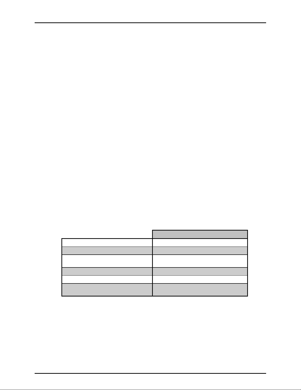
1.2.1 GENERAL SPECIFICATIONS
Power Requirements
Operating Temperature Range
Storage Temperature Range
Vibration
Weight
Dimensions
Ventilation
Communication Ports
Fuses
Pressure Ranges
Operating Medium
Internal Reservoir Capacity
Pressure Connections
85 to 264 VAC, 50/60 Hz, 75 W max consumption
15 to 35 °C
- 20 to 70 °C
Meets MIL-T-28800D
50 kg (110 lb) approx
Without optional enclosure: 26 cm H x 44 cm W x 55.5 cm D (10.2 in. x 17.3
in. x 21.9 in.) Front panel is 19” wide X 6U high with mounting holes for
standard
19 in. rack mount systems
With optional enclosure: 30 cm H x 52 cm W x 55.5 cm D
(11.8 in. x 20.5 in. x 21.9 in.)
To prevent product overheating, provide proper ventilation. Allow 10 cm
(4 in.) clearance from rear panel cooling fan.
RS232 (COM1), RS232 (COM2), IEEE-488.2
1 A, 250 VAC fuse, 5 x 20 mm, time lag type fuse
Internal power supply fuse not replaceable by operator: 2A, 250 V (UV 440-2
power supply), 3.15A, 250 V (NFS40-7612 power supply)
Four controller models from 70 MPa (10 000 psi max to 200 MPa (30 000 psi)
max.
Low uncertainty measurement provided by selection of Quartz Reference
Pressure transducer(s) (Q-RPTs)
Di-2-Ethyl Hexyl Sebacate (other fluids optional)
300 cc
DRIVE: 1/8 in. NPT F
TEST: DH500 F
NOTE: DH500 is a gland and collar type
fitting for ¼ in. (6.35 mm) coned and left
hand threaded tube. DH500 is equivalent to
EXTERNAL: 1/8 in. NPT F
AE F250C, HIP HF4, etc.
OVERFLOW: 1/8 in. NPT F
FILL/DRAIN: 1/4 in. swage M
ATM: 10-32 UNF
Pressure Limits
Maximum Working:
Test Pressure: Controller or Hi Q-RPT maximum
Maximum Test Pressure:
without Damage: 115 % controller or Hi Q-RPT maximum
Required Drive Air Pressure:
Supply:
H-100M: 700 kPa (100 psi) min, 850 kPa (120 psi)
H-140M: 500 kPa (75 psi) min, 850 kPa (120 psi)
H-70M: 500 kPa (75 psi) min, 850 kPa (120 psi)
max; 330 l/m (10 cfm)
max; 330 l/m (10 cfm)
max; 450 l/m (15 cfm)
H-200M: 700 kPa (100 psi) min, 850 kPa (120 psi)
max; 450 l/m (15 cfm)
© 2009 DH Instruments, a Fluke Company Page 2
Page 13
1. INTRODUCTION
1.2.2 PRESSURE MEASUREMENT SPECIFICATIONS
1.2.2.1 QUARTZ REFERENCE PRESSURE TRANSDUCER (Q-RPT)
Quartz reference pressure transducers (Q-RPTs) can be installed in PPCH to obtain
high precision and low uncertainty pressure measurement. One or two Q-RPTs can
be included in the PPCH and/or additional Q-RPTs can be used externally mounted
in DHI RPM4 Reference Pressure Monitors (see Section 3.2.5).
ll PPCH Q-RPTs are of the absolute pressure type (Axxx) us ing an evacuated,
A
permanently sealed reference. Axxx Q-RPTs used in PPCH can measure
absolute and gauge pressure. Gauge pressure with an Axxx (absolute) Q-RPT is
obtained by offsetting atmospheric pressure and applying dynamic compensation for
atmospheric changes using the on-board barometer (see Section 3.2.4).
See Section 3.3.3,
gauge measurement modes.
PPCHs configured with two Q-RPT modules have only one TEST port. PPCH internal
valves and logic handle switching between the two Q-RPTs as needed.
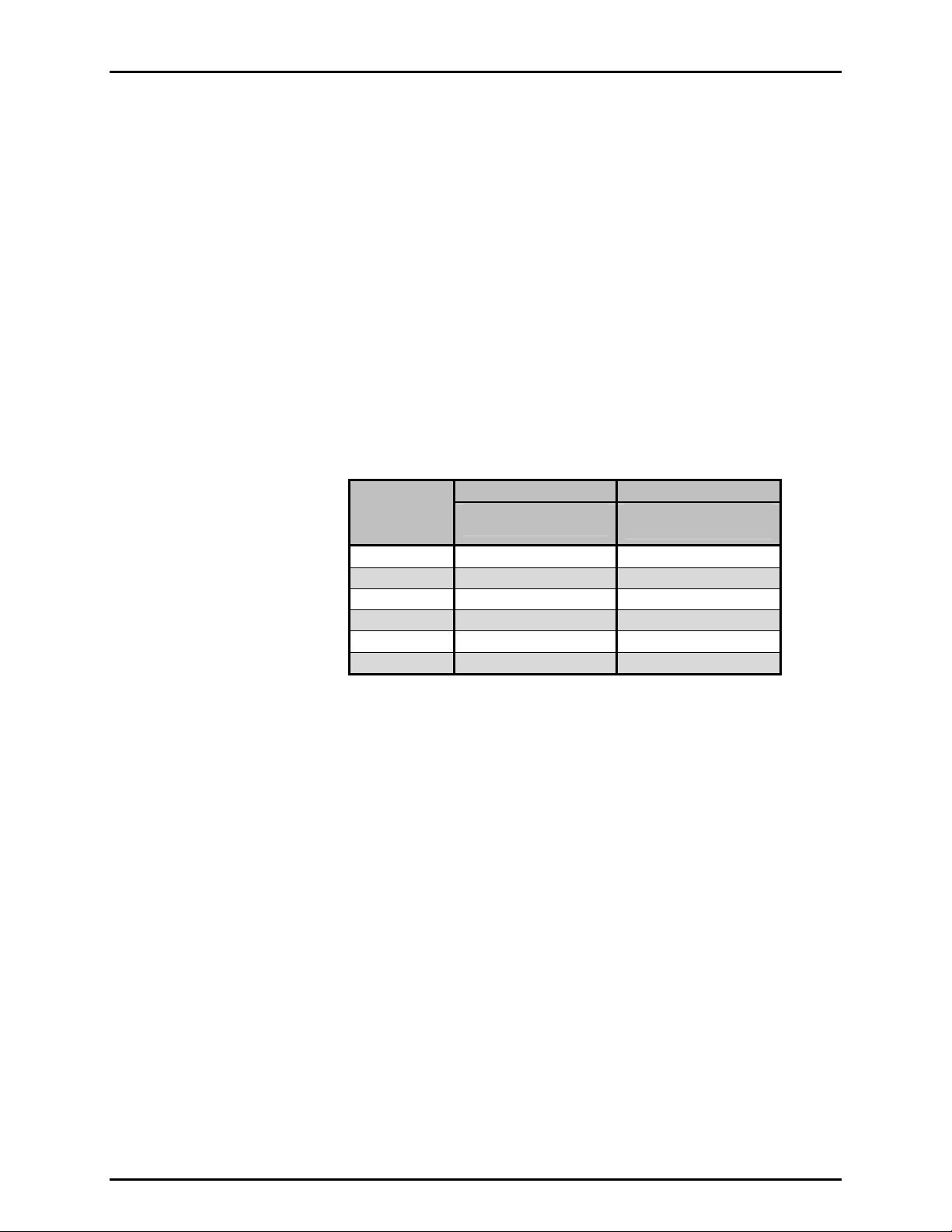
Table 1. Reference pressure transducer (Q-RPT) designations and ranges
PRINCIPLE, for additional information on absolute and
RPT
DESIGNATION
A200M 200 30 000
A140M 140 20 000
A100M 100 15 000
A70M 70 10 000
A40M 40 6 000
Compensated Temperature Range
Measurement Uncertainty3
Delivered Pressure Uncertainty4
1. Combined linearity, hysteresis, repeatability.
2. Predicted Q-RPT measurement stability limit (k=2) over one year assuming regular use of AutoZero function. AutoZero
occurs automatically in gauge mode whenever vented, by comparison with barometric reference in absolute mode.
Absolute mode predicted one year stability without AutoZ is ± (0.005 % Q-RPT span + 0.005 % of reading).
3. Maximum deviation of the Q-RPT indication from the true value of applied pressure including precision, predicted one year
stability limit, temperature effect and calibration uncertainty, combined and expanded (k=2) following the ISO “Guide to the
Expression of Uncertainty in Measurement.”
4. Maximum deviation of the PPCH controlled pressure from the true value including measurement uncertainty and dynamic
control hold limit.
5. % of reading applies to 30 to 100 % of Q-RPT span. Under 30 % of Q-RPT span, the value is a constant which is the % of
reading value times 30 %.
A20M 20 3 000
Warm Up Time
Resolution
Acceleration Affect
Precision
Predicted Stability2
SI VERSION US VERSION
MAXIMUM PRESSURE
Absolute and Gauge [MPa]
30 minute temperature stabilization recommended for
best performance from cold power up.
To 1 ppm, user adjustable
5 to 35 °C
± 0.008 % /g maximum, worst axis
Allows operation at ± 20° from reference plane without
significant effect
1
<A200M A200M
± 0.012 % of reading5 ± 0.015 % of reading5
± 0.005 % of reading5 ± 0.005 % of reading5
± 0.013 % of reading5 ± 0.018 % of reading5
± 0.015 % of reading5 ± 0.020 % of reading5
MAXIMUM PRESSURE
Absolute and Gauge [psi]
Page 3 © 2009 DH Instruments, a Fluke Company
Page 14
PPCH™ OPERATION AND MAINTENANCE MANUAL
1.2.2.2 UTILITY SENSOR
Base PPCH pressure controllers include a utility sensor. If a Hi Q-RPT
(see Section 3.2.5) is installed, there is no utility sensor.
Utility sensors are used
for pressure control, system monitoring and safety
functions. They are intended for indication only, not to provide reference
pressure measurement. Q-RPTs (see Section 1.2.2.1) are used for reference
measurement.
Warm Up Time
Range
Resolution
Precision
None required
PPCH-70M: 70 MPa (10 000 psi) absolute and gauge
PPCH-100M: 100 MPa (15 000 psi) absolute and gauge
PPCH-140M: 140 MPa (15 000 psi) absolute and gauge
PPCH-200M: 200 MPa (30 000 psi) absolute and gauge
0.001 % of span
0.1 % of span
1.2.2.3 ON-BOARD BAROMETER
The on-board barometer is used only to measure changes in atmospheric
pressure to provide dynamic compensation of the Q-RPT’s atmospheric pressure
offset when operating in gauge measurement mode. If calibrated,
it can also be used as an AutoZ reference for AutoZeroing in absolute
measurement mode.
Warm Up Time
Range
Resolution
Precision
Predicted Stability
None required
70 to 110 kPa (10 to 16 psi)
0.001 % of span
0.1 % of span
0.05 kPa/yr (0.008 psi/yr)
1.2.3 PRESSURE CONTROL SPECIFICATIONS
Control Precision (Standard Dynamic Mode)
Default Dynamic Control Hold Limit
Lowest Controllable Pressure (absolute,
gauge modes)
Typical Control Ready Time (Dynamic Mode)
Slew Rate (0 to FS)
TEST Volume
0 to 100 cc, 50 cc optimum (operates in larger
volumes but pressure stabilizing time increases)
ALL MODELS
to ± 0.003 % of Q-RPT span
± 0.01 % of AutoRanged range
1 MPa (150 psi)
60 to 120 seconds.
60 seconds
© 2009 DH Instruments, a Fluke Company Page 4
Page 15
2. INSTALLATION
22..
I
NNSSTTAALLLLAATTIIOON
I
N
2.1 UNPACKING AND INSPECTION
2.1.1 REMOVING FROM PACKAGING
PPCH is delivered in a wooden crate with high density polyethylene inserts to hold it in place.
Remove the PPCH and its accessories from the shipping container and remove each
element from its protective plastic bag.
PPCH weighs more than 50 kg (110 lb). Take appropriate precautions to lift and place it safely.
2.1.2 INSPECTING CONTENTS
Check that all items are present and have no visible damage. A standard PPCH includes all
items indicated in Table 2.
Table 2. PPCH packing list
DESCRIPTION PART #
1 ea. PPCH Pressure Controller/Calibrator FAM0010
1 ea. PPCH Enclosure (optional) 06-01
ACCESSORIES: 402038 (402038-CE)
1 ea. Operation and Maintenance Manual 550132
1 ea. Calibration Report 550100
1 ea. Test Report 550200
1 ea. Power Cord (7.5 ft.) 100770 (100770-CE)
1 ea. Reservoir fill tube assembly 402039
1 ea. Reservoir fill tube bracket 123832
2 ea. Bolts, SHC, M3 x 8 101010-Z
1 ea. Funnel 123959
1 ea. Filter/muffler, pump drive exhaust, 1/4. in. NPT M 103897
1 ea. Gland, DH200 100272
1 ea. Plug, DH200 100279
1 qt. Sebacate (synthetic oil). If PPCH is delivered filled with a fluid other than
Sebacate, this item is not included.
1 ea. Drivers Connector 401382
1 ea. General Accessories Disk (white CD) 102987
INTERCONNECTIONS KIT: 401536
2 ea. Nipple, 2.75 in., DH500 100207
1 ea. Nipple, 6 in., DH500 100208
2 ea. Nipple, 12 in., DH500 100209
1 ea. Union, DH500 100295
1 ea. Elbow, DH500 100168
1 ea. Tee, DH500 100291
2 ea. Gland, DH500 100271
3 ea. Plug, DH500 100285
5 ea. Collar, DH500 101201
1 ea. Nipple, 5 in. x 1/8 in., DH500 tips 123019
2 ea. Adaptor, DH500 F x 1/8 in. NPT M 102819
1 ea. Adaptor, DH500 F x 1/4 in. NPT F 102820
400503
or none
Page 5 © 2009 DH Instruments, a Fluke Company
Page 16

PPCH™ OPERATION AND MAINTENANCE MANUAL
2.2 SITE REQUIREMENTS
PPCH weighs more than 50 kg (110 lb). Be sure that the location in which it’s installed is adequate to
support the load.
The PPCH can be installed on any flat, stable surface at a convenient height. The PPCH can also be
mounted in a standard 19 in. rack (see Section 2.2.1).
Minimizing the distance between
the PPCH and the device or system under test will enhance control
performance and reduce pressure setting times.
Ready access to the PPCH rear panel should be considered to facilitate making and breaking
pressure connections.
Also consider:
• Access to the internal reservoir FILL/DRAIN port if an external reservoir is not being used (see
Section 2.3.6).
•
Location and connections to an external reservoir, if used (see Section 2.3.6.2).
Hydraulic and RS-232 connections to an external RPM4 should be considered if RPM4 is to be
•
used as an external reference pressure measurement device (see Section 2.3.9.1).
Location and connections to the device or system into which pressure is to be controlled (see
•
Section 2.3.9.4).
Support facilities required include:
• An electrical pow
er source of 85 to 264 VAC, 50/60 Hz.
• A pneumatic power supply, of “drive air” to be connected to the PPCH DRIVE port. Required
pressure varies with PPCH model (see Section 2.4.2).
ALWAYS use external tubing and fittings rated for pressures equal to or greater than the maximum
pressure PPCH will generate.
2.2.1 INSTALLATION IN A 19 IN. RACK MOUNT
PPCH is dimensioned to be ready for direct mounting in a standard 19 in. rack mount system.
If PPCH was delivered in the optional enclosure, it must be removed from the enclosure prior
to rack mounting.
The front panel is 6U (10.5 in.) high.
Install PPCH into the rack mount system using heavy duty front panel bolts provided by the rack
vendor. Due to PPCH’s weight, it is imperative that a rail system also be used to support it along
© 2009 DH Instruments, a Fluke Company Page 6
the sides and/or rear. These are also supplied by the rack mount system vendor.
PPCH weighs more than 50 kg (110 lb). Take appropriate precautions to lift and place it safely.
It is the user’s responsibility to support PPCH adequately on the sides and/or rear when installing it in
a rack mount system.
Page 17
2. INSTALLATION
2.3 INITIAL SETUP
2.3.1 PREPARING FOR OPERATION
To prepare PPCH for check out and operation:
Remove the plastic caps from the PPCH rear panel pressure connections.
Remove the protective plastic sheet from the front panel display.
Familiarize yourself briefly with the front and rear panel (see Section 2.3.2).
Then proceed with Sections 2.3.3 to 2.3.11.
2.3.2 FRONT AND REAR PANELS
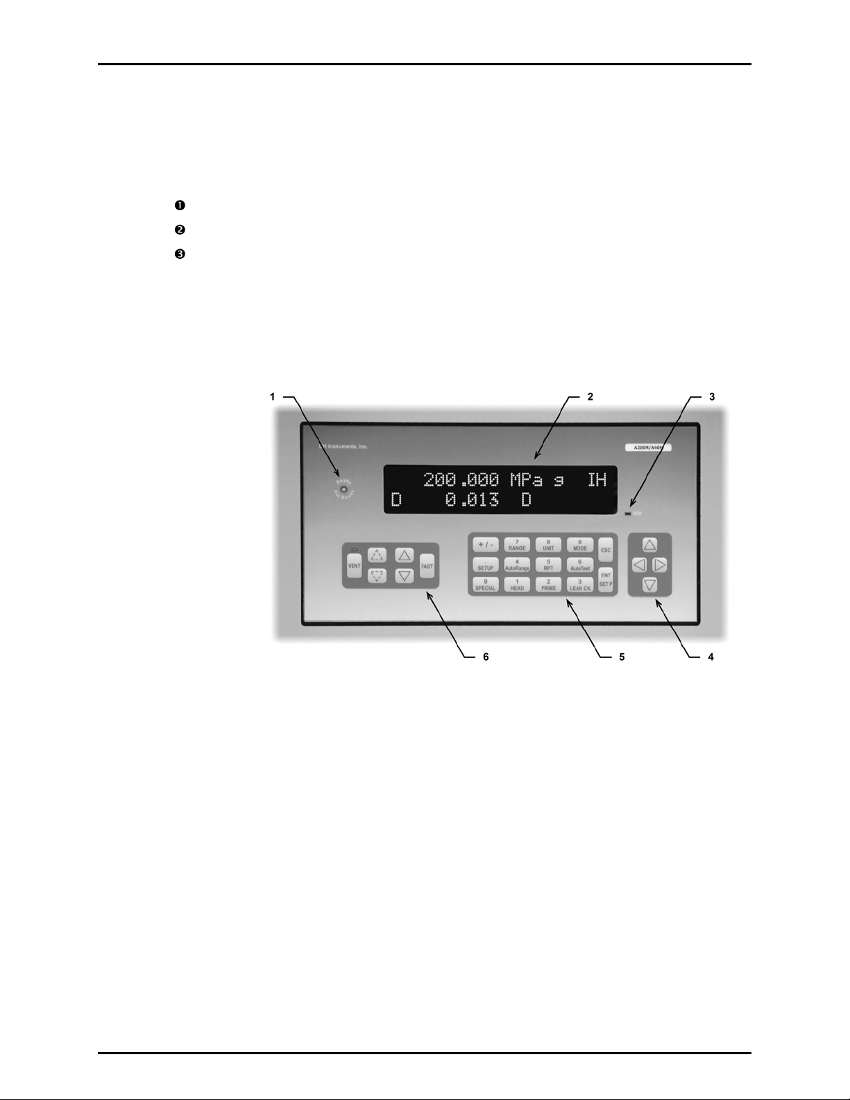
2.3.2.1 FRONT PANEL
1. Ready/Not Ready Indicator
2. Display
3. Remote activity indicator
Figure 1. Front panel
4. Cursor control keys
5. Multi-function keypad
6. Direct pressure control keys
Page 7 © 2009 DH Instruments, a Fluke Company
Page 18
PPCH™ OPERATION AND MAINTENANCE MANUAL
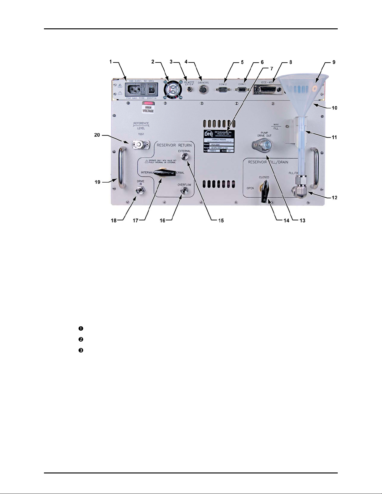
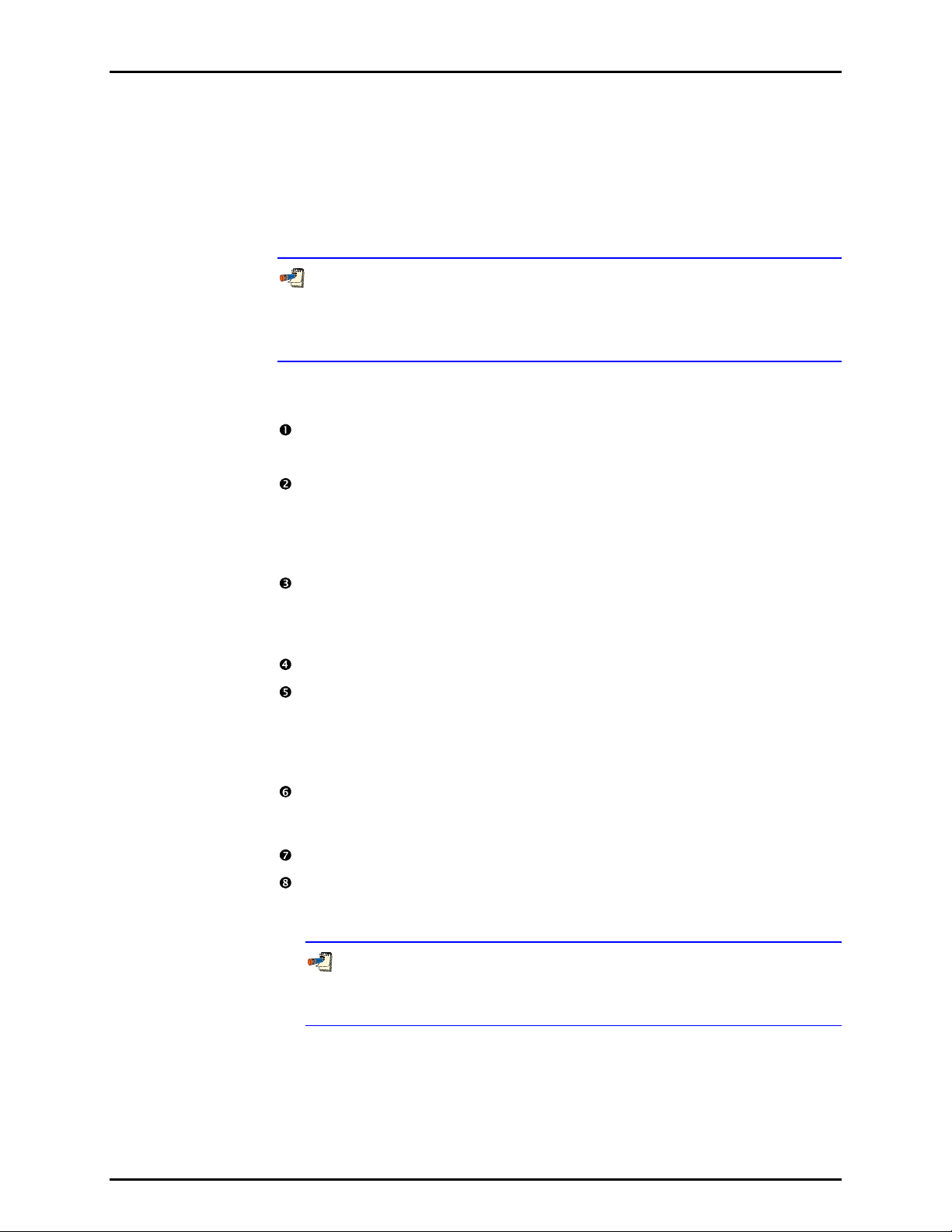
2.3.2.2 REAR PANEL
1. Electrical power connector (IEC-320C13) and fuse
2. Cooling fan
3. Remote [ENTER] connector
4. DRIVERS connector
5. RS-232 port, COM2
6. RS-232 port, COM1
7. Product label
8. IEEE-488 connector
9. ATM (barometer) port
10. Internal reservoir fill funnel
11. Internal reservoir level sight tube
12. Reservoir FILL/DRAIN port
13. PUMP DRIVE OUT gas exhaust port
14. Reservoir FILL/DRAIN valve
15. EXTERNAL reservoir return port
16. Reservoir OVERFLOW port
17. RESERVOIR RETURN valve
18. DRIVE IN air supply port
19. Mechanical module pull out handles
20. TEST port
Figure 2. Rear panel
2.3.3 POWER CONNECTION
Check that the PPCH power switch is OFF.
Connect the supplied power cable to the rear panel power input module.
Connect the other end of the power cable to an electrical supply of 85 to 264 VAC, 50/60 Hz.
2.3.4 REMOTE [ENTER/SET P] CONNECTION (FOOTSWITCH OR OTHER SWITCH)
Connect the optional remote ENTER footswitch, if available or a user supplied switch fitted to
the optional cable (see Section 7.3). Connect the cable to the PPCH rear panel connection
labeled REMOTE ENTER. Activating the switch is equivalent to
key on the front panel (see Section 3.1.4).
pressing the [ENT/SET P]
© 2009 DH Instruments, a Fluke Company Page 8
Page 19
2. INSTALLATION
2.3.5 CONNECTING PNEUMATIC POWER (DRIVE PORT)
Using a pressure connecting hose or tube of appropriate pressure rating, connect drive air supply
to the DRIVE port on the rear panel of PPCH. It is important to proper PPCH pressure control
that the supply connection not excessively restrict flow. The tube should have an ID of at least 3
mm (1/8 in.) and not be more than 2 m (6 ft) long. Generally, a 3 mm ID tube has OD of at least
6.35 mm (1/4 in.). The DRIVE port connection is 1/8 in. NPT female.
The drive air supply is regulated internally by PPCH. Drive air requirements for the different
PPCH models are listed in Table 3.
Table 3. Drive air requirements
MODEL
PPCH-70M 500 kPa (75 psi)
PPCH-100M 700 kPa (100 psi)
PPCH-140M 500 kPa (75 psi)
PPCH-200M 700 kPa (100 psi)
MINIMUM DRIVE AIR
PRESSURE
MAXIMUM DRIVE AIR
PRESSURE
850 kPa (120 psi)
MINIMUM
UNINTERRUPTED
FLOW
330 l/m (10 cfm)
450 l/m (15 cfm)
2.3.6 SETTING UP AND FILLING THE FLUID RESERVOIR
The PPCH fluid reservoir holds the fluid that supplies PPCH’s hydropneumatic pump and
returns from its exhaust valve.
PPCH has an internal reservoir with a capacity of 300 cc that is filled from and whose level can
be viewed on the rear panel of the instrument. If greater capacity and/or remote reservoir filling
and level viewing are needed, external reservoir (part number 402102) may be installed.
See Section 2.3.6.1 to set up and fill the internal reservoir.
See Section 2.3.6.2 to set up and fill an external reservoir.
Take care not to let the PPCH reservoir become empty. Operating PPCH with an empty
reservoir will cause the hydropneumatic pump to draw air and lose its prime. A pump that has
lost its prime must be reprimed using a special procedure (see Section 5.10.1). PPCH has a low
level warning displayed on the front panel that can be also checked by remote command (see
fluid
Section 3.5.7.3).
The system connected to the TEST port is connected to the reservoir when the PPCH is
vented ([VENT] LED ON). If there is an open point in the system below the fluid level in the
reservoir, liquid will run from the reservoir and out of the open point.
2.3.6.1 INTERNAL RESERVOIR
The PPCH is shipped with its internal reservoir filled with PPCH’s working fluid.
To operate without an external reservoir, the internal reservoir attachments must
be installed on the PPCH rear panel. These are included with the PPCH
accessories (see Table 2).
Page 9 © 2009 DH Instruments, a Fluke Company
Page 20
PPCH™ OPERATION AND MAINTENANCE MANUAL
The internal reservoir attachments include:
- Reservoir fill tube bracket, p/n 123832 (grey painted bracket)
- (2) M3 x 8 bolts, p/n 101010-Z
- Reservoir fill tube assembly, p/n 402039 (1/2 in. PFA tube with fittings
attached)
To prevent draining the reservoir accidentally, leave the RESERVOIR FILL/DRAIN
valve in the CLOSED position whenever the internal reservoir or external reservoir
attachments are not installed. Opening the FILL/DRAIN valve opens the FILL/DRAIN
port to the reservoir.
To set up to use the internal reservoir without an external reservoir, proceed as
follows (numeric references refer to Figure 3):
Install the reservoir fill tube bracket(1) to the PPCH rear panel using 2 ea. M3
x 8 bolts(3).
- Funnel p/n 123959
Install the reservoir fill tube assembly(4) by connecting the 1/4 in. swage
female on the assembly to the 1/4 in. swage male FILL/DRAIN connection.
Remove and retain the stainless steel cap that is installed on the connection
as delivered. Orient the PFA tube vertically. Bend the tube slightly to extend
through the reservoir fill bracket.
There is a red plug with a center pull tab in the end of the PFA tube. This
should be left in place when the funnel is not being used to prevent
contamination and/or evaporation of the fluid. The funnel(2) can be stored in
the holder just behind the tube.
Open the FILL/DRAIN valve(5). Fluid may enter the fill drain tube(4).
Check that the EXTERNAL port(6) is plugged. It is plugged when delivered.
If it is not, use a 1/8 in. NPT M plug with Teflon® tape on the threads to plug
it. Not plugging the EXTERNAL port when using the internal reservoir only
will cause the fluid exhausted from the PPCH to leak out rather than
returning to the reservoir.
Check that the OVERFLOW port(7) is open to atmosphere and
unobstructed. This assures the reservoir is open to atmosphere so proper
system venting and zeroing can occur.
Be sure the RESERVOIR RETURN valve(8) is on the INTERNAL position.
Check the level of the fluid in the fill/drain tube. If the level is below the MAX
FILL position, top off the tank. See Section 5.6.1 for information on filling
and draining the PPCH internal reservoir.
The PFA reservoir fill tube is delivered with a red plug with a center pull tab
installed. This plug can be used after the tube is installed to cover the opening
and reduce evaporation of the fluid. The plug is vented.
© 2009 DH Instruments, a Fluke Company Page 10
Page 21
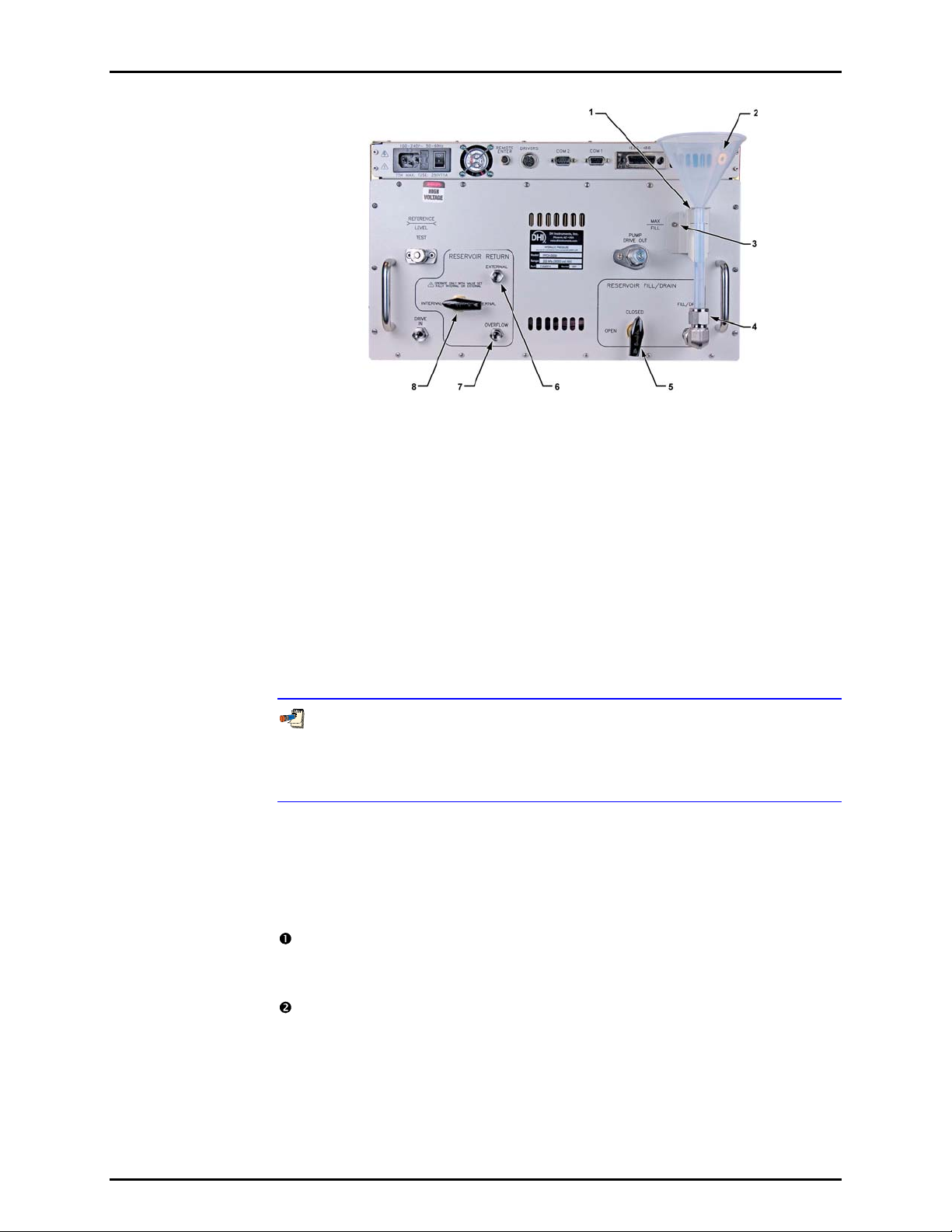
2. INSTALLATION
1. Reservoir fill tube bracket
2. Reservoir fill funnel
3. M3 x 8 bolt
4. Reservoir fill tube assembly
Figure 3. Internal reservoir setup
5. Reservoir FILL/DRAIN valve
6. EXTERNAL Reservoir return port
7. Reservoir OVERFLOW port
8. RESERVOIR RETURN valve
2.3.6.2 EXTERNAL RESERVOIR
The PPCH is shipped with its internal reservoir filled with PPCH’s working fluid.
An external reservoir, if desired, is connected in series to supply the internal
reservoir so that the internal reservoir’s features are still available.
When using an external reservoir the internal reservoir attachments are NOT
installed. If they have been installed, remove them prior to setting up the
external reservoir (see Section 2.3.6.1). Be sure to put the FILL/DRAIN valve in
the CLOSED position before removing the fill/drain tube assembly.
To prevent draining the reservoir accidentally, leave the RESERVOIR FILL/DRAIN
valve in the CLOSED position if the internal or external reservoir attachments are not
installed. Opening the FILL/DRAIN valve opens the FILL/DRAIN port to the internal
reservoir.
When installing an external reservoir, the bottom of the reservoir should be
higher than the PPCH instrument. Avoid low points in the tubing between the
PPCH and the external reservoir.
To set up to use an external reservoir, proceed as follows (numerical references
refer to Figure 4):
With the reservoir FILL/DRAIN valve in the CLOSED position, connect a
tube coming from the bottom of the external reservoir to the FILL/DRAIN
port(1). The FILL/DRAIN port is1/4 in. M swage.
Connect an external reservoir return tube from the EXTERNAL port(3) to the
inside of the reservoir. Remove and retain the 1/8 in. NPT plug installed in
EXTERNAL port as shipped. The reservoir return tube returns fluid
exhausted by PPCH to the external reservoir. The top of the tube should
extend vertically to a level slightly higher than the top surface of the fluid in
the reservoir. The top of the tube defines the fluid head applied to the PPCH
Q-RPT when the PPCH is vented (see Section 5.6.2, Figure 20).
Page 11 © 2009 DH Instruments, a Fluke Company
Page 22
PPCH™ OPERATION AND MAINTENANCE MANUAL
Fill the external reservoir with fluid. This should be the same fluid that is in
the PPCH. PPCH will not operate properly with a fluid other than the liquid
with which it was filled when delivered. The MAX FILL label on the rear of
the PPCH does not apply when using an external reservoir.
Purge air from the internal reservoir and overflow circuit:
a. Prepare an 1/8 in. NPT plug (one was delivered installed in the
EXTERNAL port) by wrapping its threads with Teflon tape.
b. While watching the OVERFLOW port(4), slowly turn the
RESERVOIR FILL/DRAIN valve(2) to the OPEN position.
c. When air free fluid begins to flow from the OVERFLOW port, plug
the port with the 1/8 in. NPT plug.
Be sure the RESERVOIR RETURN valve(5) is in the EXTERNAL position.
Be sure the external reservoir is open to atmosphere so proper system
venting and zeroing can occur.
Fill the reservoir return tube connected between the reservoir and the
EXTERNAL port with fluid. See Section 5.6.2 for additional information in
filling and draining an external reservoir.
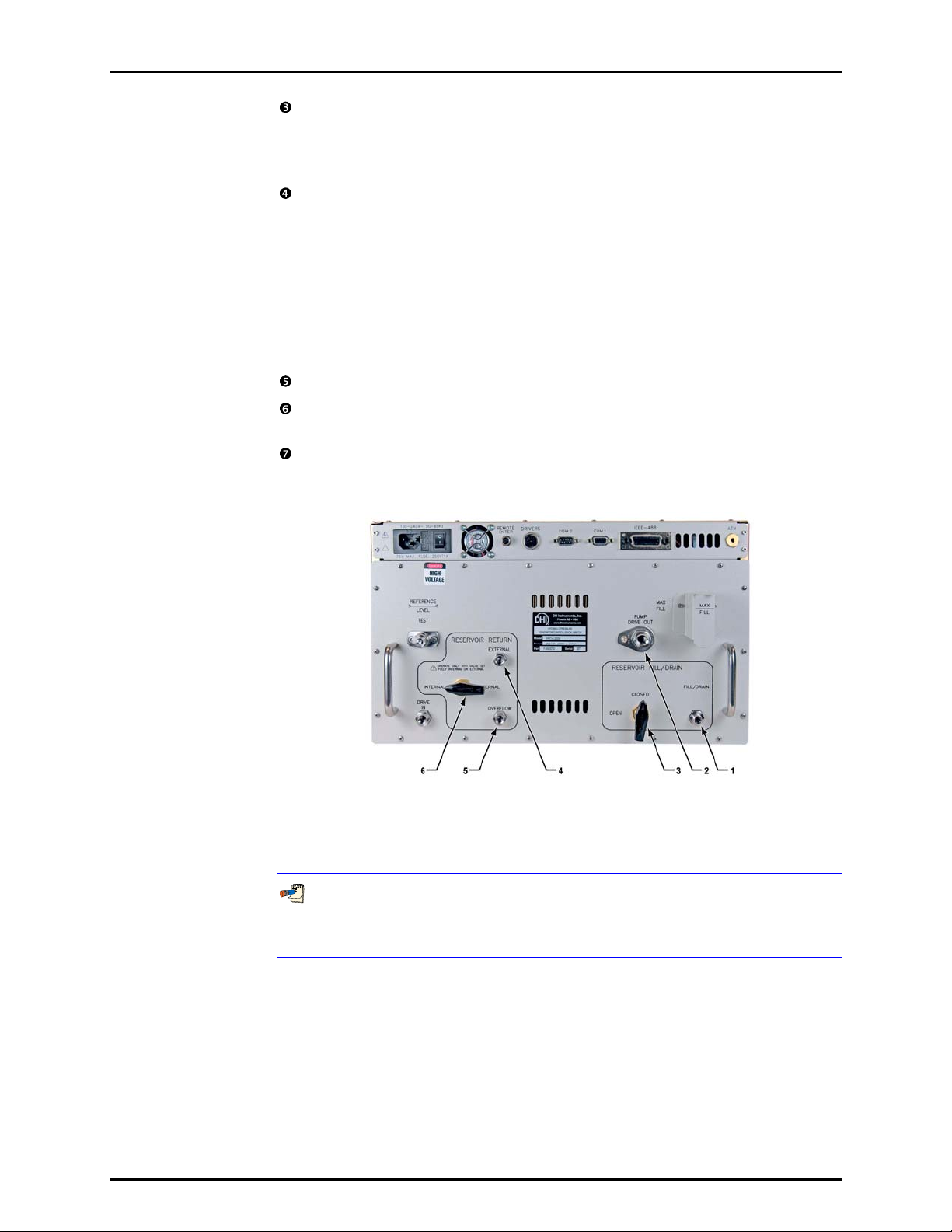
1. Reservoir FILL/DRAIN port
2. PUMP DRIVE OUT gas exhaust port
3. Reservoir FILL/DRAIN valve
Figure 4. External reservoir setup
When the PPCH is vented ([VENT] LED ON), the system connected to the TEST
port is connected to the reservoir. If there is an open point in the system below the
fluid level in the reservoir, liquid will run out of the reservoir through the open point.
2.3.7 RESERVOIR RETURN SETTINGS
The PPCH rear panel has a section labeled RESERVOIR RETURN. The settings and
connections in this panel vary depending on whether the internal reservoir is being used
alone or an external reservoir is being used.
Refer to Table 4 for correct reservoir return settings and other conditions when using the
internal reservoir alone or an external reservoir. Also see Section 2.3.6 for internal and
external reservoir setups.
© 2009 DH Instruments, a Fluke Company Page 12
4. EXTERNAL Reservoir return port
5. Reservoir OVERFLOW port
6. RESERVOIR RETURN valve
Page 23
2. INSTALLATION
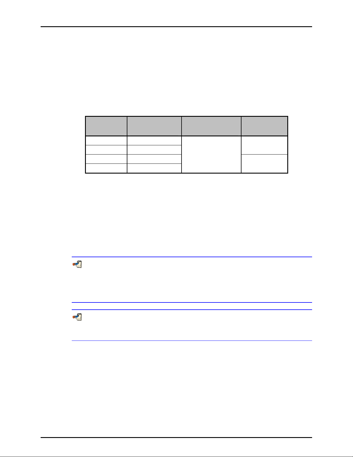
Table 4. Reservoir return settings for internal or external reservoir
RESERVOIR
RESERVOIR
Internal only INTERNAL Open to
External EXTERNAL Plugged Connected to external
RETURN VALVE
POSITION
OVERFLOW
PORT EXTERNAL PORT
Plugged
atmosphere
reservoir return tube
See Section 5.6, Figure 19 and Figure 20 for schematics of the PPCH reservoir system.
Incorrect settings or port conditions in the RESERVOIR RETURN panel may lead to fluid
leaks and faulty measurements.
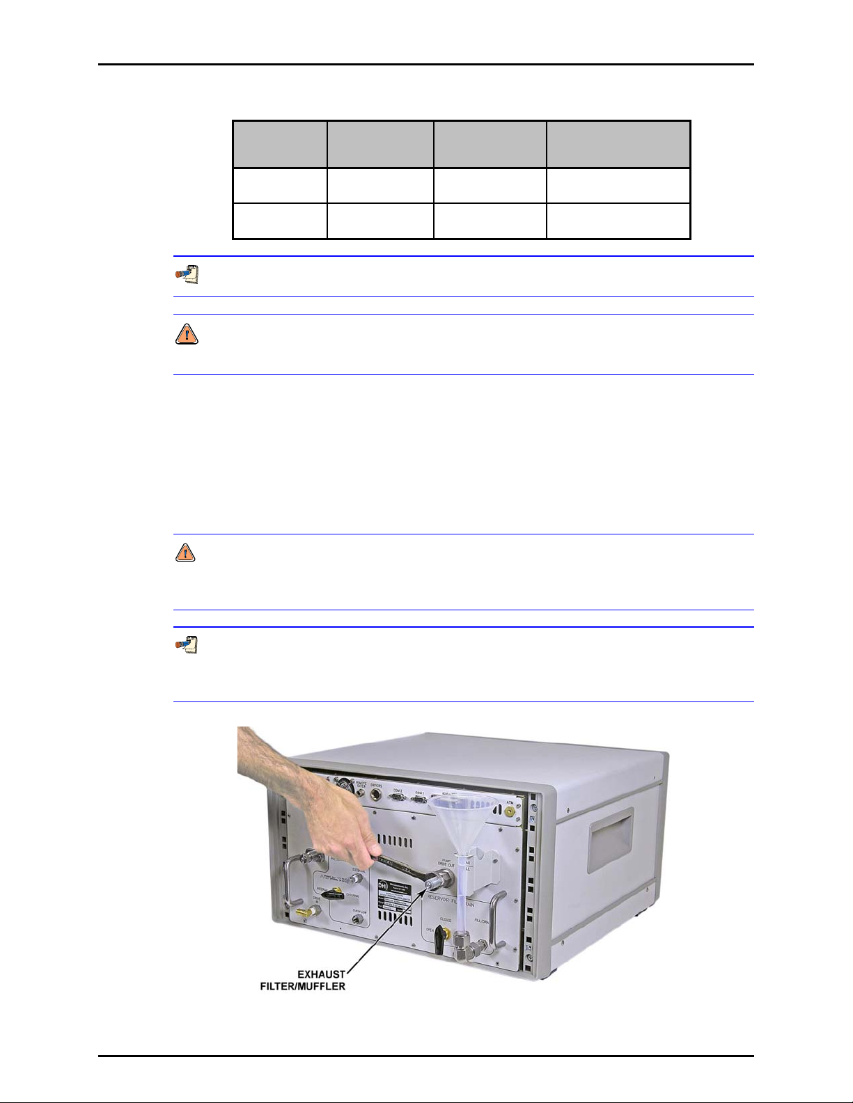
2.3.8 INSTALLING PUMP DRIVE OUT GAS EXHAUST FILTER/MUFFLER
A stainless steel filter (P/N 103897) is supplied in the PPCH accessory kit. The filter dampens
the sound of supply gas being exhuasted from the hydro-pneumatic pump. To install the filter,
first wrap 1 to 2 turns of teflon tape around the threads then insert the threaded end of the muffler
into the Pump Drive Out port using a 9/16" wrench as shown in Figure 5. Do not overtighten.
It is important to use a wrench to install the filter instead of a screwdriver. The button head
screw on the end of the filter adjusts the conductance of the muffler. If the muffler is too restrictive
then the hydropneumatic pump will stall and the PPCH may not be able to increase pressure.
The filter/muffler is adjusted for conductance at the factory. If the filter adjustment is
altered it can be returned to the factory setting by using a screwdriver to turn the button head
screw clockwise until it stops then turning it one and half turns counterclockwise.
Figure 5. Installing the exhaust filter/muffler
Page 13 © 2009 DH Instruments, a Fluke Company
Page 24
PPCH™ OPERATION AND MAINTENANCE MANUAL
2.3.9 CONNECTING TO OTHER DEVICES
ALWAYS use external tubing and fittings rated for pressure equal to or greater than the
maximum pressure PPCH will be used to generate.
The PPCH TEST port is a DH500 female fitting.
DH500 is a gland and collar type fitting for 1/4 in. (6.35 mm) coned and left hand threaded
tube. DH500 is equivalent to AE F250C, HIP HF4, etc.
DH500 fittings are rated for working pressure up to 500 MPa (72 500 psi). Be sure to use
stainless steel tubing rated for your maximum operating pressure with the DH500 fittings.
2.3.9.1 INSTALLING A LINE FILTER TO PROTECT THE PPCH
PPCH uses pressure shutoff valves that are needle valves that close by the
metal to metal contact of the needle in its seat. These valves can be damaged
by hard particles. If the test system to which PPCH will be connected may
contain hard particles, such as metal shavings from a production process, a line
filter should be installed on the PPCH test port to prevent the particles from
entering the PPCH when reducing pressure. The filter should not be smaller
then 40 micron. DHI recommends high pressure filter kit p/n 402376.
2.3.9.2 CONNECTING TO AN RPM4 TO BE USED AS AN EXTERNAL REFERENCE DEVICE
ALWAYS use external tubing and fittings rated for pressure equal to or
greater than the maximum pressure PPCH will be used to generate.
PPCH can be connected hydraulically and by RS-232 to one or two RPM4
reference pressure monitors to use up to four external Q-RPTs (two in each RPM4)
as external reference pressure measurement devices (see Section 3.2.5).
The PPCH then manages communications and other
integrate the RPM4 measurement capabilities into the PPCH system. The user
is responsible for setting up hardware and following procedures to isolate
lower pressure Q-RPTs from possible overpressure if pressures higher
than the Q-RPT maximum are generated.. PPCH and RPM4 do not have
hardware provisions for isolating external Q-RPTs from the TEST circuit.
As a general rule, making the hydraulic connection between the PPCH TEST
port and the remote Q-RPT as direct as possible favors good pressure control. As
distance, volumes and restrictions between the PPCH TEST port and the remote QRPT increase, the possibility of difficulty with pressure control when using the
external Q-RPT increases.
RPM4 functions to
© 2009 DH Instruments, a Fluke Company Page 14
Page 25
2. INSTALLATION
To connect a PPCH to an RPM4 to be used as part of the PPCH system proceed
as follows:
Set up the RPM4 for use as a PPCH external device following the instructions
in the RRPM4 Operation and Maintenance Manual, Using RPM4 With a PPC3
Controller/Calibrator Section.
Using tubing of appropriate pressure rating and a tee fitting, connect the
RPM4 Q-RPT TEST(+) port to the PPCH TEST port (see Figure 6 for
instructions
on making this connection using the standard interconnection
accessories supplied with the PPCH). The third leg of the tee is for the
connection to the device or system under test.
When external Q-RPTs are used with PPCH, the maximum set pressure is
the maximum pressure of the PPCH controller/calibrator. The maximum pressure
of the PPCH is determined by the PPCH controller model or the Hi Q-RPT if one is
installed (see Section 1.2.1).
Using a standard pin-to-pin DB-9M to DB-9F RS232 cable, connect COM2 of
the PPCH to COM1 of the RPM4 (see Section 4.2.1.3).
Turn ON the RPM4 and the PPCH.
Press [RPT] on the PPCH key pad. This causes PPCH to execute the
Q-RPT search function (see Section 3.3.5). Following the search, Q-RPTs
with whom communication is established
are shown on the PPCH display,
identified by their position (see Table 6).
For PPCH to identify external RPM4s, the RPM4 COM port settings
must be:
Baud rate: between 1200 and 19200
Parity: Even
Data bits: 7
Stop bits: 1
If PPCH is not able to establish communications with an RPM4 and its
Q-RPTs, check that the RPM4 COM1 port settings conform to the requirements
above. If the COM1 port settings are correct, check that the correct communications
cable is being used (standard pin-to-pin DB-9M to DB-9F RS232) and is connected
to the correct communications ports.
PPCH COM2 > 1st RPM4 COM1; 1st RPM4 COM2 > 2nd RPM4 COM1
See the RPM4 Operation and Maintenance Manual for additional information on
RPM4 RS232 communications and COM port settings.
Page 15 © 2009 DH Instruments, a Fluke Company
Page 26
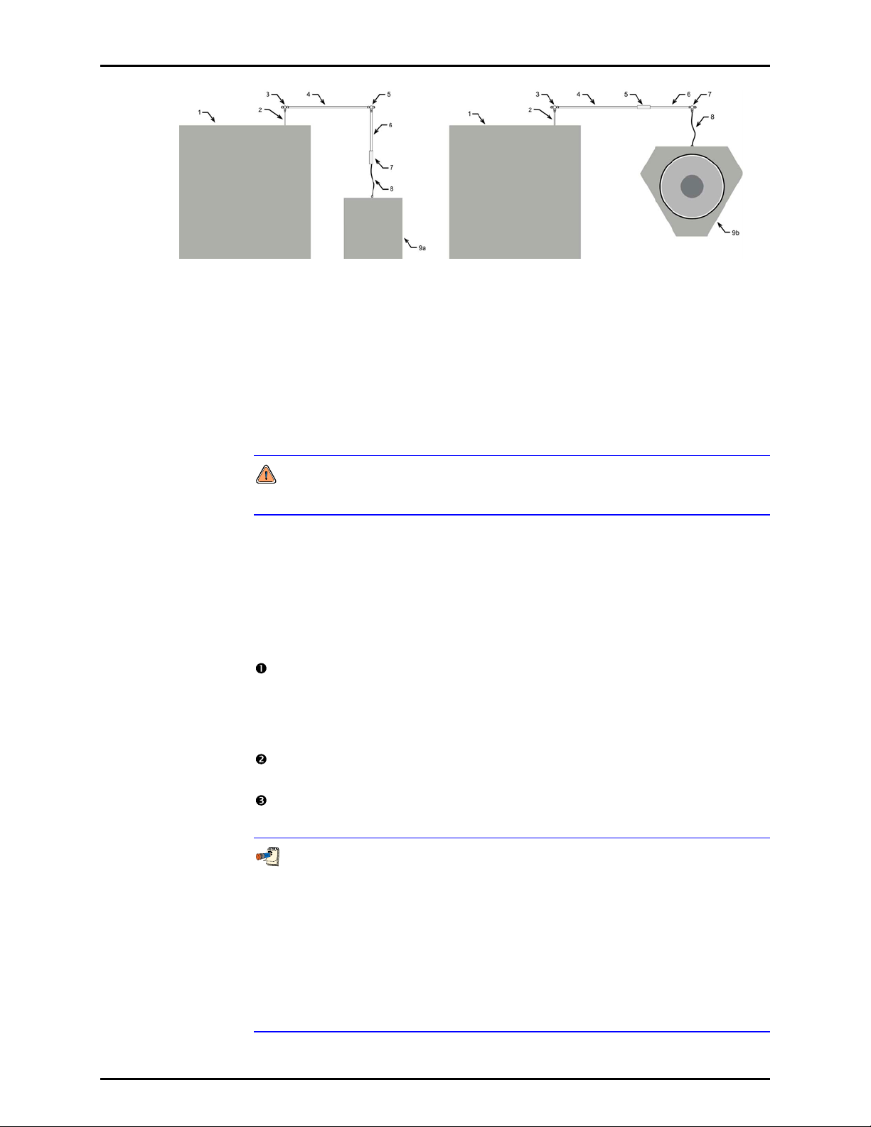
PPCH™ OPERATION AND MAINTENANCE MANUAL
1. PPCH
2. 2.75 in. (70 mm) DH 500 nipple
3. DH500 tee
4. 12 in. (305 mm) DH500 nipple
5. DH500 tee (RPM4) or union (PG7000)
6. 6 in. (152 mm) DH500 nipple
Figure 6. Connecting PPCH to an RPM4 or PG7302 using the standard
PPCH interconnection accessories
2.3.9.3 CONNECTING TO A PG7302 PISTON GAUGE
7. DH500 union (RPM4) or tee (PG7000)
8. 5 in. (127 mm) DH500 x 1/8 in. tube
weld nipple (slightly flexible)
9a. RPM4 or RPM3
9b. PG7000
ALWAYS use external tubing and fittings rated for pressure equal to or
greater than the maximum pressure PPCH will be used to generate.
PPCH is frequently used as the automated pressure generation and control
component in a PG7302 oil operated piston gauge system. To do so, it must be
connected hydraulically and by RS-232 to the PG7302.
The PG7302 puts the PPCH into remote mode and manages its operation.
To connect a PPCH to a PG7302 to be used as an automated pressure
generation and control component in the PG7302 system, proceed as follows:
Using tubing of appropriate pressure rating and a tee fitting, connect the
PG7302 TEST port to the PPCH TEST port (see Figure 6 for instructions on
making this connection using the standard interconnections
accessories
supplied with the PPCH). The third leg of the tee is for the connection to the
device or system under test.
Using a standard pin-to-pin DB-9M to DB-9F RS232 cable, connect COM1 of
the PPCH to COM3 of the PG7302.
See the PG7000 Operation and Maintenance Manual for information on
operating the PG7302 with an automated pressure controlling device.
For PPCH to be identified by a PG7302 platform, the PPCH-COM1 port settings
must be the same as the PG7302 COM3 settings (baud rate, parity, data bits, stop
bits). If the PG7000 is not able to establish communications with PPCH, check that
the PPCH COM1 port settings are the same as the PG7302 COM3 settings. If the
COM port settings are correct, check that the correct communications cable is being
used (standard pin-to-pin DB-9M to DB-9F RS232) and is connected to the correct
communications ports.
See the PG7302 Operation and Maintenance Manual for additional information on
PG7302 RS232 communications and COM port settings.
© 2009 DH Instruments, a Fluke Company Page 16
Page 27
2. INSTALLATION
2.3.9.4 CONNECTING TO A DEVICE UNDER TEST (TEST PORT)
ALWAYS use external tubing and fittings rated for pressure equal to or
greater than the maximum pressure PPCH will be used to generate.
Using a pressure connecting hose or tube of appropriate pressure rating,
connect the device or system to be tested to the PPCH TEST port. The PPCH TEST
connection is DH500 female.
DH500 is a gland and collar type fitting for 1/4 in. (6.35 mm) coned and left
hand threaded tube. DH500 is equivalent to AE F250C, HIP HF4, etc.
Minimizing the length of the test connection tubing will enhance control
performance and reduce pressure setting time. For normal operation, the optimum
total volume of the device or system under test including connecting tubing is 50 cc
3
) and should be less than 100 cc (6 in3).
(3 in
PPCH pressure control will not operate properly if there are excessive leaks in
the system connected to its TEST port. In general, the maximum acceptable leak
rate for optimal PPCH automated pressure control operation and to assure in
tolerance measurements with default pressure control parameters is 0.005 % of
reading/second. In DYNAMIC CONTROL mode, to handle higher test system leak
rates, increase the hold limit using CUSTOM CONTROL (see Section 3.4.6.1) or use HI
VOLUME DYNAMIC CONTROL (see Section 3.2.2.2).
When the PPCH is vented ([VENT] LED ON), the system connected to the TEST
port is connected to the reservoir. If there is an open point in the system below the
fluid level in the reservoir, liquid will run out of the reservoir through the open point.
2.3.10 CHECK/SET SECURITY LEVEL
PPCH has a security system based on user levels. By default, the security system is set to
“low”, which includes certain access restrictions, and there is no password required to
change the security level. See Section 3.5.5.5 for information on the security level system.
As part of the PPCH startup, determine the security level that is appropriate for the PPCH
and set a password if desired.
PPCH is delivered with the security level set to “low” to avoid inadvertent altering of critical
internal settings but with access to changing security levels unrestricted. It is recommended that
the low security level be maintained at all times and password protection be implemented if
control over setting of security levels is desired.
Page 17 © 2009 DH Instruments, a Fluke Company
Page 28

PPCH™ OPERATION AND MAINTENANCE MANUAL
2.3.11 TURN OFF ABSOLUTE MEASUREMENT MODE
PPCH Q-RPTs can operate in both absolute and gauge measurement modes (see Section
3.3.3). If the PPCH will only be used in gauge mode, absolute measurement mode may be
turned off for its Q-RPT(s) so it is no
accidental use of the wrong measurement mode. See Section 5.3.5 for complete information
on turning off absolute measurement mode.
longer accessible. This can avoid confusion and/or
2.4 POWER-UP AND VERIFICATION
2.4.1 SWITCH POWER ON
Actuate the power switch on the PPCH rear panel. Observe the front panel display as PPCH
initializes, error checks and goes to the MAIN RUN screen (see Section 3.1.1).
PPCH
pressure measured by the Hi Q-RPT is more than 100 kPa (15 psi) away from standard
atmospheric pressure.
If the PPCH fails to reach the MAIN RUN screen, service is required. Record the sequence
of operations and displays observed. Contact a DHI Authorized Service Provider (see Table 31).
power-up condition is Internal, Hi Q-RPT or utility sensor active, VENT ON unless the
2.4.2 APPLY PNEUMATIC POWER (DRIVE AIR)
Apply pneumatic power of the appropriate pressure and flow rate to the PPCH DRIVE port
(see Section 2.3.5). It is normal for the hydropneumatic
drive air is applied.
pump to cycle a few times when
2.4.3 CHECK PRESSURE MEASUREMENT OPERATION
2.4.3.1 CHECKING ABSOLUTE MODE PRESSURE MEASUREMENT
Check that the PPCH operates properly in absolute mode.
If the PPCH is not vented (VENT LED ON), press the [VENT] direct pressure
control key (see Section 3.1.3).
Use the [RANGE]
Q-RPT’s DF range (see Section 3.3.1). Press the [MODE] function key and
select
<absolute> (see Section 3.3.3). Use [UNIT] to change the pressure unit if
desired (see Section 3.3.2).
function key to change ranges if necessary and select the
Observe the current value of atmospheric pressure.
with the local value of atmospheric pressure. Repeat this process for all the QRPTs and or the utility sensor in the PPCH system. Check that the values of
atmospheric pressure measured by the different devices agree with each other
within PPCH or RPM4 measurement tolerances as applicable (see Section
1.2.2.1, 1.2.2.2). Remember to consider that head pressures can be
with liquids (see Section 3.3.7). If the Q-RPTs do not agree within tolerances,
the PPCH or RPM4 Q-RPT may need calibration or repair.
© 2009 DH Instruments, a Fluke Company Page 18
Check that the value agrees
significant
Page 29
2. INSTALLATION
2.4.3.2 CHECKING GAUGE MODE PRESSURE MEASUREMENT
If the PPCH is not vented (VENT LED ON), press the [VENT] direct pressure
control key to vent it (see Section 3.1.3).
Use the [RANGE]
function key to change ranges if necessary and select the
Q-RPT’s DF range (see Section 3.3.1). Press the [MODE] function key and
select
<gauge> mode (see Section 3.3.3). Use [UNIT]
to change the pressure
unit if desired (see Section 3.3.2).
t is normal for PPCH to indicate a value other than zero for up to thirty seconds
I
when first entering gauge mode. After ten to thirty seconds, the VENT LED
should flash and zero should be indicated. If this does not occur, check that the
AUTOZERO function is ON (see Section 3.5.1). If AUTOZERO is ON and the
displayed
pressure will not zero when vented in gauge or bi-directional gauge
measurement mode, PPCH may need repair.
If a non-zero head correction value is active, PPCH will not indicate zero when
vented in gauge mode. Use [HEAD] to set the head height to zero (see Section 3.3.7).
Using the [RANGE] function key to change ranges, observe that zero is
indicated for each Q-RPT within 10 to 30 seconds.
2.4.4 PRIME AND PURGE TEST SYSTEM
For PPCH pressure control to operate properly, it is important to minimize the amount of gas
present in the system connected to the TEST port. The prime and purge functions are
intended to assist in removing gas from the test system before starting a test.
Prior to controlling pressure with PPCH, it is recommended that a priming and/or purging
procedure be completed (see Section 3.3.8).
2.4.5 LEAK CHECK
PPCH cannot control pressure properly if the system connected to the TEST port has excessive
leaks. See Section 3.3.9 or information on the PPCH leak
test function.
For PPCH to operate properly, the leak rate in the test system after stabilization should not
exceed 0.005% of reading/second.
Verify the maximum pressure rating of the system connected to the PPCH TEST port before
entering a purge pressure value. Do not enter a purge pressure greater than the pressure rating
of the system or instruments connected to the PPCH TEST port.
2.4.6 CHECK PRESSURE CONTROL OPERATION
Select a pressure range using [RANGE] (see Section 3.3.1).
Press [SETUP], <6control>, <2mode>, <1dynamic>, <1standard>) (see Section 3.4.6). If
PCH was not already set to dynamic control mode, wait 5 minutes for the thermal pressure
controller to stabilize.
P
ress [ENT]. Key in a target pressure within the active range and press [ENT] again
(see Section 3.3.10).
Page 19 © 2009 DH Instruments, a Fluke Company
Page 30
PPCH™ OPERATION AND MAINTENANCE MANUAL
Verify the maximum pressure rating of the system connected to the PPCH TEST port before
entering a target pressure. Do not enter a target pressure greater than the pressure rating of
the system or instruments connected to the PPCH TEST port.
PPCH should set the target pressure and indicate Ready (see Section 3.2.3) continuously in
60 to 120 seconds. If it does not, see Section 6 to troubleshoot.
2.5 STORAGE AND SHIPPING
2.5.1 SHORT TERM STORAGE
The following procedure is recommended for short term storage of PPCH:
Vent the PPCH test pressure.
If the PPCH TEST port is open to a point lower than the reservoir, when PPCH is vented
([VENT] LED ON), the liquid contained in the reservoir may leak out through the opening.
Turn the power OFF using the rear panel power switch.
Shut OFF or disconnect the drive air pressure supply.
2.5.2 LONG TERM STORAGE
The following procedure is recommended for long term storage of PPCH:
Complete the short term storage procedure (see Section 2.5.1).
Plug the TEST port with a DH500 steel plug.
Set the RESERVOIR FILL/DRAIN valve to CLOSED and the RESERVOIR RETURN
valve to INTERNAL.
2.5.3 PREPARATION FOR SHIPPING
The following procedure is recommended to prepare PPCH for shipment:
Complete the long term storage procedure (see Section 2.5.2).
Remove the internal reservoir accessories if they have been installed (see Section 2.3.6.1).
Pack PPCH carefully being sure to use packing materials appropriate for shipment of a
delicate instrument weighing approximately 50 kg (110 lb.). If available, use the original
packing materials.
© 2009 DH Instruments, a Fluke Company Page 20
Page 31

3. OPERATION
33..
O
PPEERRAATTIIOON
O
N
3.1 USER INTERFACE
PPCH is designed to offer a practical balance between simple, straight forward operation and the
availability of a wide variety of advanced functions with a high level of operator discretion. The local
operator interface is through a 2 x 20 display, a function/data keypad, a cursor control pad and direct
pressure control keys.
Remote communication is by RS232 (COM1) or IEEE-488. See Section 4 for information on remote
communication.
3.1.1 MAIN RUN SCREEN
The PPCH MAIN RUN screen is its home display that is reached on power-up and from which
other functions and menus are accessed. It is the very top level of all menu structures.
The MAIN RUN screen is where the operator works with PPCH to set and read pressures.
It provides complete information on the system’s current configuration and operating status.
Table 5 summarizes the PPCH MAIN RUN screen fields and their functions.
PPCH has a screen saver function which causes the display to dim if no key is pressed for
10 minutes. Pressing a key restores full power to the display. The screen saver time can be
changed or screen saving can be completely suppressed (see Section 3.5.5.1).
Page 21 © 2009 DH Instruments, a Fluke Company
Page 32

PPCH™ OPERATION AND MAINTENANCE MANUAL
Table 5. MAIN RUN screen display fields
PRESSURE1UNITM hzRRH
TPRESSURE2 CC NN/NN
DISPLAY FIELD NAME PURPOSE CONTENTS SECTION
1. PRESSURE1 Measured
2. UNIT Unit of
3. M Measurement
4. h Head
5. z AutoZero
6. RRH Active Q-
7. NN/NN Sequence
8. CC Pressure
Displays pressure
pressure
measured by active
Q-RPT or utility
sensor
Identifies unit of
measure
measure in which
PRESSURE1 and
PRESSURE2 are
displayed
Identifies
mode
measurement mode
of displayed pressure
Indicates whether a
pressure
indicator
fluid head correction
is applied to
PRESSURE1
Indicates whether
indicator
the AutoZero
function is ON or
OFF
Indicates the position
RPT position
indicator
in the PPCH system
of the active Q-RPT
or utility sensor
Indicates progress of
progress
indicator
an ATest sequence,
during test execution
Indicates type of
control
indicator
pressure control,
whether control is
currently active and
whether custom
control limits are in use
Numerical pressure
value and sign
1.2.2.1
1.2.2.2
3.3.10
Pressure unit of
3.3.2
measure abbreviation
<a>: absolute
3.3.3
<g>: gauge
<h>: the fluid head
3.3.7
is not zero
<blank>: fluid head is
zero
<z>: AutoZ is ON
3.5.1
<blank>: AutoZ is OFF
<IH>: Internal Hi
3.2.5
<IuH>: Internal Hi
(utility sensor)
<IL>: Internal Lo
<X1H>: External 1 Hi
<X1L>: External 1 Lo
<X2H>: External 2 Hi
<X2L>: External 2 Lo
<NN/NN>: Number of
3.3.6
this point over total
number of points in the
sequence
<D>: Control mode is
standard dynamic
<d>: Control mode is
3.2.1
3.4.6
hi volume dynamic
<S>: Control mode is
static
<M>: Control mode is
monotonic
<R>: Control mode is
rate
<C> is appended to the
control character if
control limits are custom
Control character(s)
flash when PPCH is
actively controlling
© 2009 DH Instruments, a Fluke Company Page 22
Page 33

3. OPERATION
DISPLAY FIELD NAME PURPOSE CONTENTS SECTION
9. TPRESSURE2 Pressure
information
indicator
Pressure indication
depending on current
PPCH function.
Leading character
identifies the value.
<R>: Pressure rate of
change in current
pressure unit/second
<T>: Pressure control
target
<D>: Deviation from the
pressure control
target
<Reservoir level low>:
Indicates that the
reservoir needs to be
filled urgently.
3.3.10
3.5.7.3.2
3.1.2 FUNCTION / DATA KEYPAD LAYOUT AND PROTOCOL
The PPCH has a function/data keypad for local operator access to direct functions, function
menus and for data entry.
1. The Function/Data keys allow very commonly
used functions to be accessed directly by a
single keystroke when pressed from the
MAIN RUN screen (see Section 3.1.1). The
name
of the function is on the bottom half of
the key. These keys enter numerical value s
when editing.
2. The Editing and Execution keys are for
starting and suspending command execution,
cursor control in menus and editing entries.
Figure 7. Keypad layout
3. The Menu/Data keys provide access to
function menus when pressed from the
MAIN RUN screen. The menu name is on
the bottom half of the key. The SETUP
menu is for more frequently used functions
(see Section 3.4). The SPECIAL menu is
for functions that are not generally
a part of day to day operation (see
Section 3.5). These keys enter numerical
values w
hen editing.
used as
Pressing the [ENT/SET P] key generally causes execution or forward movement in the menu
tree. Pressing [ENT/SET P] from the MAIN RUN screen allows an automated pressure
control command to be given.
Pressing the [ESC] key moves back in the menu tree and/or causes execution to cease or
suspend. Pressing [ESC] repeatedly eventually returns to the MAIN RUN screen and, from
there, allows momentary viewing of the PPCH introduction screen.
Pressing the [+/-] key changes a numerical sign when editing. It also toggles through
multiple screens when available and is a shortcut to a momentary display of the active
RANGE from the MAIN RUN screen.
Pressing the [
], [ ], [ ] and [ ] keys allows reverse, forward and up, down cursor
movement when editing data entry or moving in menus.
Page 23 © 2009 DH Instruments, a Fluke Company
Page 34

PPCH™ OPERATION AND MAINTENANCE MANUAL
Some screens go beyond the two lines provided by the display. This is indicated by a
flashing down arrow in the second line of the display. Press the cursor control keys to move the
cursor to access the lines that are not visible or directly enter the number of the hidden menu
choice if you know it.
3.1.3 DIRECT PRESSURE CONTROL KEYS
Figure 8. Direct pressure control keys
The direct pressure control keys provide direct manual control of pressure increase,
decrease, jog and vent. They can be useful in adjusting pressure when automated pressure
control to a target pressure or rate is not needed. The jog keys are also used to adjust the
target pressure during active dynamic pressure control.
Pressing the [VENT] key aborts automated pressure control if active and causes PPCH to
control pressure to near atmospheric pressure and then open the system vent valve (see
Figure 9). On-going execution of
the vent function is indicated by lighting a RED LED just
above the [VENT] key. Completion of the vent process is indicated by the Ready/Not Ready
indicator light becoming GREEN with the vent RED vent LED still lighted. The vent valve
remains open until the [VENT] key is pressed again, another direct pressure control key is
pressed, or an automated pressure control command is given. Removing electrical power
also closes the vent valve.
Pressing the [
] and [ ] direct pressure control keys aborts automated pressure control if
active and causes pressure to increase or decrease at the slow slew rate. Holding the
[FAST] key pressed while pressing the [
] or [ ] key causes the pressure increase or
decrease speed to change from slow to fast.
Pressing the [
] and [ ] direct pressure control keys has a different effect depending on
the PPCH’s current activity:
• Pressure control idle: Causes the pressure to jog or step by a fixed amount which is
set automatically depending on the range (see Section 3.4.6, Table 10). The amount can
be adjusted u
sing [SETUP], <3jog> or by pressing both the up and down jog keys
simultaneously (see Section 3.4.3).
• Dy
namic pressure control active: Causes the target pressure to be changed by a fixed
amount which is set automatically depending on the range. One press causes one step.
The step value can be adjusted using [SETUP], <3jog> or by pressing both the up and
down jog keys simultaneously (see Section 3.4.3).
• Static pressure control activ
e: No effect while pressure is actively controlled, changes
pressure by jog amount when pressure is in hold limit waiting for stability.
• Monotonic pressure control active: No effect.
• Ramp control active: No effect.
Pressing the up and down pressure jog keys ([ ] and [ ])simultaneously is a shortcut
to the jog step size adjustment menu.
© 2009 DH Instruments, a Fluke Company Page 24
Page 35

3. OPERATION
3.1.4 REMOTE [ENT/SET P] (FOOT)SWITCH
The optional remote ENTER function is a switch that duplicates the function of the front panel
[ENT] key. The remote ENTER function is serviced by a connector on the PPCH rear panel
labeled REMOTE ENTER. An optional footswitch is available to activate remote entry hands
free or a user supplied switch may be used. See Section 7.3 for information on remote
NTER switch wiring.
E
The remote ENTER feature can be particularly convenient when running AutoTests
(see Section 3.3.6) in which using a footswitch to [ENT] allows hands free operation.
3.1.5 SOUNDS
PPCH is equipped with a variable frequency tone device to provide audible feedback and
alarms. The beeper is used for the following indications.
Valid key press Brief beep. Choice between three frequencies
or NO sound is available (see Section 3.5.5.2).
alid key press Descending two tone “blurp”.
Inv
Leak check completed Three two second beeps (see Section 3.3.9).
Purge routine completed Three two second beeps (see Section 3.3.8.2).
Upper limit exceeded Intermittent one second beeps (see Section 3.4.4)
Activ
e external device not connected Eight second high frequency beep (see Section
3.2.5)
Pmax! (ov
AutoTest reading in tolerance/out of Ascending triad/descending triad (see Section
tolerance reading 3.3.6).
Reserv
erpressure limit) exceeded Eight second high frequency beep (see Section
3.4.4.1).
oir level low Ten brief beeps (see Section 3.5.7.3.2).
3.2 GENERAL OPERATING PRINCIPLES
3.2.1 PRESSURE CONTROL PRINCIPLES
Numerical references in this section refer to Figure 9.
PPCH is designed to precisely generate, measure and control liquid pressure into a volume
connected to its TEST port (13). Pressure is measured by a utility sensor or one or two
Quartz Reference Pressure Transducers (Q-RPT)(15, 18).
Pressure is generated internally using a hydropneumatic pump(19). The hydropneumatic
pump uses the ratio of two pistons to transform low pressure drive air into high pressure
liquid output. The drive air pressure is controlled by an internal pressure regulator(3).
The liquid supply to the pump is from an internal or external reservoir. Liquid returned from
the test system when reducing pressure is returned to the internal or external reservoir via a
return tube that provides a constant fluid level when the system is vented. Provision is made
for filling, draining, returning liquid to and viewing the level of the internal or external reservoir
(6, 7,8,9,10) (see Section 5.6). Should the system be run with the reservoir empty causing
the pump to draw air and lose
the pump(4, 5) (see Section 5.10.1).
The hydropneumatic pump high pressure output supplies
The inlet valve is a pressure balanced needle valve whose needle position is controller by a
stepper motor and belt drive. The inlet valve provides very high precision control of the liquid
Page 25 © 2009 DH Instruments, a Fluke Company
its prime, the internal reservoir can be pressurized to reprime
a servo-controlled inlet valve(17).
Page 36

PPCH™ OPERATION AND MAINTENANCE MANUAL
admitted to the test system from the hydropneumatic pump to the test system. An outlet
valve(11) of the same type as the inlet valve precisely controls liquid exhaust.
The inlet and exhaust valve can adjust and maintain pressure rates of change very precisely.
When conditions are appropriate, a second stage of pressure control is used to maintain a
target pressure value within very narrow hold limits in dynamic control mode. The second
stage is thermal pressure control (TPC). TPC, uses a pressurized volume in which there is a
heating element and around which there is a forced air cooling system(14). Heating and
cooling the fluid in the volume causes it to expand or contract, increasing or decreasing
pressure. This pressure control system allows extremely fine pressure control without
hysteresis or wear of mechanical parts.
The TPC system response is dependent on the operating liquid and the volume connected to
the TEST port. It is minimally effective when there are leaks in the test system or the test
volume is large. PPCH automatically determines whether conditions are appropriate to use
TPC and runs an automated routine to determine the test volume. This routine is initiated
automatically when needed.
© 2009 DH Instruments, a Fluke Company Page 26
Page 37

3. OPERATION
1. DRIVE air port
2a. Drive air supply filter
2b. Pump inlet filter (liquid)
3. Drive air regulator
4. Drive air control manifold
5. Three-way reservoir pressure valve
6. OVERFLOW port
7. Reservoir fill/drain valve
8. Reservoir fill/drain/level tube
9. Reservoir return valve
10. EXTERNAL return port
11. Outlet valve, servo-controlled
Figure 9. Pressure control system schematic
Page 27 © 2009 DH Instruments, a Fluke Company
12. Vent valve, pneumatically controlled
13. TEST port
14. Thermal pressure control unit (TPCU)
15. Hi Q-RPT
16. High pressure filter(s)
17. Inlet valve, servo-controlled
18. Lo Q-RPT, shutoff valve, vent valve,
pneumatically controlled
19. Hydropneumatic pump
20. Pump drive out vent port and filter/muffler
21. Two-way hydropneumatic pump cutoff valve
22. Pump drive air pressure transducer
Page 38

PPCH™ OPERATION AND MAINTENANCE MANUAL
3.2.2 AUTOMATED PRESSURE CONTROL
PPCH automated pressure control provides automated generation and control of pressure to
a user designated target value or ramp rate.
See Section 3.3.10 for information on using [ENT/SET P] to set pressure automatically and
abort automated pressure control.
PPCH supports four pressure control modes to meet different pressure setting and controlling
requirements: dynamic, static, monotonic and ramp. Pressure control parameters for each
control mode are automatically set to optimal default values for the operating PPCH range
when the range is selected or AutoRange is used (see Section 3.3.4). Control parameters
can be customized using the [SETUP], <6control> function (see Section 3.4.6.1).
Control parameters:
Target Value
The pressure set point or ramp rate specified by the operator (dynamic,
static, monotonic, ramp modes).
Target Limit Setting short of the target value (monotonic mode).
Hold Limit A symmetrical positive and negative control limit around a target value
within which the controlled pressure or rate is maintained (dynamic,
static, ramp modes).
Rate Limit A rate of change of pressure limit in the same sign as the direction in
which pressure is controlled in units of pressure/second (monotonic
mode).
Stability Limit An absolute value rate of change of pressure limit in units of
pressure/second (static mode and control not active).
See this Section 3.2.2 and Sections 3.2.2.1 to 3.2.2.5 for a detailed explanation of each
control mode and its advantages, the default control parameters and the control customization
options.
3.2.2.1 IDLE, NO AUTOMATED CONTROL (MEASURE MODE)
In any control mode, PPCH pressure control can be interrupted so that no control
occurs. Control inactive is indicated by the pressure control indicator characters
on the MAIN RUN screen NOT flashing. The control character(s) is/are the two
characters in the center of the bottom line of the display (see Section 3.1.1).
To abort control when control
]. [ENT/Set P] does NOT abort control in monotonic mode.
or [
When control is idle (measure mode), a Ready condition occurs any time the
pressure stability test is met (see Section 3.2.3).
© 2009 DH Instruments, a Fluke Company Page 28
is active press [ENT/Set P], [ESC], [VENT], [
]
Page 39

3. OPERATION
3.2.2.2 DYNAMIC CONTROL
Dynamic control mode is designed to set the pressure to the target value and
control continuously to keep pressure within the hold limit and as close to the
target value as possible (see Figure 10).
advantage of this control mode is that the final pressure achieved is the
The
same as the target value. The maximum value of the control error is equal to the
hold limit. The average value of the control error is generally much smaller than
the hold limit.
During dynamic pressure control, the hold limit is active. If the pressure goes
outside of the hold limit, a Not Ready condition occurs. See Table 10 for default
hold limit values and Section 3.4.6 to customize the hold limit.
There are two types of dynamic control. Standard dynamic control is the default
type of dynamic control
also available for situations in which standard dynamic control cannot achieve a
Ready condition in a reasonable amount of time and/or cannot maintain the
Ready condition once achieved. Hi volume dynamic control may be necessary
when the test volume connected to the PPCH is greater than 100 cc. The
difference between standard and hi volume dynamic pressure control is in the
use of the thermal pressure controller (TPCU). In standard dynamic control,
control transitions from the control valves to the TPCU before Ready occurs and
the target pressure is reached. In hi volume dynamic control, control is by the
valves only unless they valves are unable to maintain the Ready condition.
used in most situations. Hi volume dynamic control is
Figure 10. Dynamic pressure control operation
PPCH includes a Ready/Not Ready feature that indicates when current pressure
control requirements have been met (see Section 3.2.3).
With dynamic pressure control active, a Ready condition occurs whenever:
The current measured pressure is inside the hold limit.
•
Figure 11 illustrates Ready/Not Ready operation in dynamic control mode.
In dynamic control mode, normal procedure is to assume that when a Ready
condition occurs (pressure inside the control hold limit), the measured pressure
equals the target pressure. For this reason, when the pressure is Ready in dynamic
control mode, the measured pressure display is equal to the target pressure.
Page 29 © 2009 DH Instruments, a Fluke Company
Page 40

PPCH™ OPERATION AND MAINTENANCE MANUAL
Figure 11. Ready/Not Ready in dynamic pressure control mode
3.2.2.3 STATIC CONTROL
Static control mode is designed to set the pressure near the target value and
then interrupt active control to allow pressure to stabilize naturally within the hold
limit (Figure 12).
advantage of this control mode is that pressure can be set and/or measured
The
within a defined limit of a target without interference from the pressure control
system. In a system without excessive leaks, the pressure stability achieved
may be greater than the stability with which the pressure control system can
actively control pressure. Using static control to control pressure near the
desired set point and then measuring back the stabilized pressure without
interference of the control function can allow control errors to be completely
eliminated. However, the final pressure achieved is not equal to the target value
and the time required to achieve sufficiently stable pressure is dependent on the
characteristics of the test volume and may be longer than in other modes.
During static pressure control, the hold limit is active. If the pressure goes outside of
the hold limit, pressure is readjusted to the target value. Se e Table 10 for default
hold limit values and Section 3.4.6 to customize the hold limit.
Figure 12. Static pressure control operation
© 2009 DH Instruments, a Fluke Company Page 30
Page 41

3. OPERATION
PPCH includes a Ready/Not Ready feature that indicates when current pressure
control requirements have been met (see Section 3.2.3).
With static pressure control active a Ready condition occurs whenever:
•
NO control valve is operating.
• The current measured pressure is at the target value within the hold limit.
• The rate of change of pressure is less than the current stability limit.
Figure 13. Ready/Not Ready in static control mode
3.2.2.4 MONOTONIC CONTROL
Monotonic control mode is designed to set pressure increments and take data
from a device under test while assuring the evolution of pressure is always in the
same direction (ascending for ascending increments, descending for descending
increments). In monotonic control mode the pressure is set near the target value
and then controlled at a low rate of change in the same direction as the target
pressure approach (see Figure 14). Measured pressure data is taken from the
Figure 13 illustrates Ready/Not Ready operation in Static control mode.
PPCH
target pressure.
and output from the device under test during the slow ramp near the
The advantage of this control mode is that in a sequence of pressures,
ascending or descending increments are set without overshoot or oscillation as
is desirable when determining the hysteresis of a device under test (DUT). This
method also tends to achieve a ready condition more quickly than dynamic or
static control. However, the final pressure achieved is not equal to the target
value and for best results it is necessary to average alternating PPCH and DUT
readings to compensate for possible timing differences in the readings.
When setting a monotonic pressure point, PPCH attempts to set a ramp rate less
than the rate limit at the near end of the pressure target limit and then maintains
the ramp rate until a new pressure target value is entered or the range “upper
limit” (UL) is reached (see Section 3.4.4). If the ramp rate exceeds the specified
target rate or changes
default pressure and ramp rate target limit
sign, a Not Ready condition occurs. See Table 10 for
values and Section 3.4.6 to customize
the limits.
Page 31 © 2009 DH Instruments, a Fluke Company
Page 42

PPCH™ OPERATION AND MAINTENANCE MANUAL
Figure 14. Monotonic pressure control operation
PPCH includes a Ready/Not Ready feature that indicates when current pressure
control requirements have been met (see Section 3.2.3).
With monotonic pressure control active, a Ready condition occurs whenever:
•
PPCH has reached the target pressure has passed the target limit and is
controlling ramp rate at less than the rate limit.
Figure 15 illustrates Ready/Not Ready operation in monotonic control mode.
Figure 15. Ready/Not Ready in monotonic pressure control mode
3.2.2.5 RAMP CONTROL
Ramp control is designed to set a pressure ramp at a target rate and maintain
the rate within a rate hold limit (see Figure 16). This control mode can be used
for a variety of calibration and testing functions.
When setting a ramp, PPCH attempts to establish the target rate within the rate
hold limit as quickly as possible and then maintains the rate until a
command is given or the active range “upper limit” is reached (see Section
3.4.4). If the rate is outside of the rate hold limit, a Not Ready condition occurs.
See Table 10 for default target rate and hold limit values and Section 3.4.6 to
customize the hold limit.
© 2009 DH Instruments, a Fluke Company Page 32
new
Page 43

3. OPERATION
Figure 16. Ramp pressure control operation
*Note that Figure 15 plots rate of change of pressure, not pressure.
PPCH includes a Ready/Not Ready feature that indicates when current pressure
control requirements have been met (see Section 3.2.3).
With ramp pressure control active, a Ready condition occurs whenever:
•
PPCH is controlling rate at the target rate value within the rate hold limit.
Figure 17 illustrates Ready/Not Ready operation in ramp control mode.
Figure 17. Ready/Not Ready in ramp pressure control mode
*Note that Figure 16 plots rate of change of pressure, not pressure.
Page 33 © 2009 DH Instruments, a Fluke Company
Page 44

PPCH™ OPERATION AND MAINTENANCE MANUAL
3.2.3 PRESSURE READY/NOT READY
There is a Ready/Not Ready indication LED on the PPCH front panel. Ready/Not Ready
status is also available remotely. This indication is intended to provide the operator with a
clear and objective criterion for determining when a valid pressure measurement can be made.
The Ready/Not Ready LED indications are:
<Green, no flash> Pressure Ready, control idle. PPCH is NOT actively controlling the
pressure. This indicates no control is occurring and the pressure
stability is within the stability limit.
<Green, slow flash> Pressure Ready, control active. PPCH is actively controlling the
pressure and the criteria for a Ready condition to occur in the active
control mode have been met.
<Red > Pressure Not Ready. Either PPCH is idle and pressure does not meet
the stability limit or PPCH is actively controlling the pressure and
Ready conditions have not yet been met. The control characters in
the middle of the second line of the MAIN RUN screen flash if control
is active (see Section 3.1.1).
When automated pressure control is idle (measure mode): A
Ready condition occurs
any time the pressure rate of change is inside the stability limit. The stability limit is defined in
terms of rate of change of pressure in current pressure units per second. The stability limit is
set by default (see Table 10) and can be customized (see Section 3.4.6).
When pressure control is activ
e: The criteria for determining the Ready/Not Ready
condition depend on whether the current control mode is static, dynamic, monotonic or ramp
(see Sections 3.2.2.2, 3.2.2.3, 3.2.2.4, 3.2.2.5). Pressure Ready/Not Ready parameters are
by default when AutoRange is used, or a control mode is selected (see Table 10).
set
The parameters can be customized if desired (see Section 3.4.6).
3.2.4 GAUGE MEASUREMENT MODE, DYNAMIC
COMPENSATION FOR ATMOSPHERIC PRESSURE
PPCH utility sensors and Q-RPTs are intrinsically absolute but they are also used in gauge
measurement mode (difference from atmosphere) (see Section 3.3.3, P
measurement mode is achieved by subtracting the value of atmospheric pressure, P
the Q-RPT’s absolute reading using AutoZ (see Section 3.5.1). In gauge measurement
mode,
the AutoZ routine that measures P
, is run automatically whenever the PPCH is in
offset,G
the vented condition. This assures the continuous automated updating of the P
corresponding to atmospheric pressure. Gauge pressure is the mea sure d abs olut e pre ssur e,
, minus the atmospheric offset.
P
u
P
gauge
= Pu - P
offset,G
However, atmospheric pressure can change between opportunities to run AutoZ and update
the value of P
, for example when running an extended test without venting. PPCH uses
offset,G
dynamic compensation for atmospheric pressure to correct for these changes in
atmospheric pressure. When AutoZ executes, and P
PPCH’s on board barometer, P
change in atmospheric pressure, ΔP
the current barometer reading, P
execution, P
atm,0
:
, is also recorded. Later, when no longer vented, the
atm,0
, since P
atm
, and the barometer reading at the time of AutoZ
atm
ΔP
= P
atm
atm
was updated, is the difference between
offset,G
- P
atm,0
Dynamic compensation for atmospheric pressure uses ΔP
is determined, the reading of
offset,G
to correct the value of P
atm
thus always compensating real time for changes in atmospheric pressure:
RINCIPLE). Gauge
, from
offset,G
value
offset,G
,
offset,G
P
= Pu - P
gauge
© 2009 DH Instruments, a Fluke Company Page 34
offset,G
- ΔP
atm
Page 45

3. OPERATION
PPCH Q-RPTs allow instantaneous switching between gauge and absolute measurements
modes. Any additional uncertainty in gauge measurement mode due to the dynamic
compensation for atmospheric pressure technique is a function of the resolution and short
term stability of the on-board barometer, not its absolute measurement uncertainty.
This additional uncertainty, ± 1 Pa (0.00015 psi), is insignificant in the pressure ranges
covered by PPCH.
3.2.5 MULTIPLE INTERNAL AND EXTERNAL Q-RPTS
A base PPCH pressure controller includes a high precision, utility pressure sensor whose
range is equal to the controller’s range. The utility sensor is not intended to serve as a
pressure reference for low uncertainty measurement. It is for indication, pressure control,
system safety and maintenance functions only.
To obtain low uncertainty, traceable pressure measurement, PPCH uses Quartz Reference
Pressure Transducers (Q-RPT). Up to six Q-RPTs can be included in a PPCH pressure
controller/calibrator system. One or two Q-RPTs can be built into the PPCH, up to two may be
located outside the PPCH enclosure in RPM4 reference pressure monitors (one or two per
RPM4). Once the Q-RPTs available to a PPCH system have been set up and identified,
communication with them is managed by PPCH transparently to the operator. However,
setting up hardware and following procedures to protect lower pressure Q-RPTs from
overpressure when higher pressure Q-RPTs are used is the responsibility of the user.
Take precautions not to overpressure external Q-RPTs when using them with a PPCH. When
using external Q-RPTs in RPM4s as reference pressure measurement devices with a PPCH, the
user is responsible to setting up hardware and following procedures to protect lower range QRPTs from overpressure. Only the Lo Q-RPT (IL) built-into the PPCH is protected automatically.
Communication between RPM4s and a PPCH controller is by daisy chained RS232
connections from PPCH’s COM2 port.
The PPCH RPT function (see Section 3.3.5) is used to identify Q-RPTs available to the
PPCH.
The PPCH then manages communication with the internal and external Q-RPTs
transparently to the operator, selecting the appropriate Q-RPT for the range of operation and
configuring it as specified.
Each Q-RPT has a default range, which is its maximum range. It can also be downranged
using PPCH’s AutoRange function.
Before operating PPCH with an external Q-RPT, check carefully that the RPM4’s Q-RPT
TEST(+) port is connected to the PPCH TEST port. If an external Q-RPT is NOT connected to the
PPCH TEST port, it will NOT measure the pressure generated by PPCH and PPCH may reach a pressure
higher than the target pressure before its watchdog function recognizes that the external Q-RPT
is not connected (see Section 3.4.4.1). The PPCH watchdog function monitors differences in the
change in pressure indicated by an active,
external Q-RPT and the PPCH Hi utility sensor or Q-RPT
(watchdog). If the difference becomes excessive, control is aborted, an audible warning sounds
and a warning is displayed.
If this occurs, make sure the PPCH and RPM4 Q-RPT TEST(+) ports are connected together and
try again.
Position Identification of Q-RPTs In a PPCH System
Position identification of the currently active Q-RPT or utility sensor in the PPCH system is
continuously displayed in the upper right hand corner of the PPCH’s MAIN RUN screen and
most other screens (see Section 3.1.1). See Table 6 for position designation prot ocol f or th e
Q-RPTs available in a PPCH system.
Page 35 © 2009 DH Instruments, a Fluke Company
Page 46

PPCH™ OPERATION AND MAINTENANCE MANUAL
See Table 1 for a complete listing of Q-RPTs available and their default ranges.
Table 6. Position designators of Q-RPTs in a PPCH system
Q-RPT POSITION IDENTIFICATION DISPLAY SYMBOL*
Internal to PPCH, utility sensor, if present Internal Utility, Hi IuH
Internal to PPCH, Q-RPT of maximum
range
Internal to PPCH, Q-RPT with lower
maximum range in PPCH with two QRPTs or a utility sensor and Q-RPT.
External to PPCH, Q-RPT of higher
maximum range in 1st RPM4 on
PPCH/RPM4 communications daisy
chain
External to PPCH, Q-RPT with lower
maximum range in dual Q-RPT RPM4
that is the 1
communications daisy chain
External to PPCH, Q-RPT of higher
maximum range in 2nd RPM4 on
PPCH/RPM4 communications daisy
chain
External to PPCH, Q-RPT with lower
maximum range in dual Q-RPT RPM4
that is the 2
communications daisy chain
• The display symbol is included in the upper, right hand corner of most PPCH displays and menus as a
convenient indicator of the active Q-RPT.
st
RPM4 on the PPCH/RPM4
nd
RPM4 on the PC3/RPM4
Internal, Hi IH
Internal, Lo IL
External 1, Hi X1H
External 1, Lo X1L
External 2, Hi X2H
External 2, Lo X2L
3.2.6 MULTIPE RANGES (Q-RPTS, AUTORANGE AND INFINITE RANGING)
A PPCH range is defined as a pressure span and associated settings.
A PPCH may have multiple ranges. Each Q-RPT (and the utility sensor, if present) available to the
PPCH system has a default range which is its maximum span. Additional ranges, lower than the QRPT’s maximum span, may be created using AutoRange (see Section 3.3.4). Ranges created
using AutoRange may be saved with all their settings for reactivation later (see Section 3.4.1).
PPCH range is identified by a range screen showing the Q-RPT used by the range, its current
A
unit of measure and its full scale pressure in gauge and absolute (if available) measurement modes.
The range screen is viewed by pressing [RANGE] or [+/-] from the MAIN RUN screen.
1. Q-RPT or utility sensor designator.
2. Type of range. <DF> for the Q-RPT’s default range; <AR> for a
range created by AutoRange.
3. Q-RPT or utility sensor position designator.
4. Current pressure unit of measure.
5. Full scale pressure in current unit of measure in gauge and/or
absolute measurement mode depending on the measurement modes
available.
Most settings made in a PPCH range, such as unit of measure, measurement mode, display
resolution, control mode and control parameters are specific to the range. The range specific
settings are stored with the range and recalled whenever the range is made active. This makes
setting up and saving ranges a convenient way to store and recall frequently used operating
configurations. See Table 7 for a listing of PPCH adjustments and settings and whether they
are range, Q-RPT o
r system specific.
Active A100M DF IH
psi 15000g/15000a
© 2009 DH Instruments, a Fluke Company Page 36
Page 47

3. OPERATION
The ranges available on a PPCH system are accessed using [RANGE] (see Section 3.3.1)
and/or created using [AutoRange] (see Section 3.3.4). External Q-RPTs connected to the
PPCH (see Section 3.2.5) are initialized using [RPT] (see Section 3.3.5).
Table 7. Settings and to what they are specific (range, measurement mode, Q-RPT, system)
SETTING PURPOSE SPECIFIC TO SECTION
Unit Set pressure unit of measure Range 3.3.2
Mode Set pressure measurement mode
Resolution Set pressure display resolution Range 3.4.2
Jog Set jog step size Range 3.4.3
Control Set pressure control mode and
Upper Limit Set upper limit alarm Range and measurement mode 3.4.4
AutoZ Run AutoZ, ON/OFF, set and view value Range and measurement mode 3.5.1
Screen
Saver,
Sound,
Time, ID,
Level
Head Set fluid head correction height, fluid, unit
Valve
Drivers
Cal Various Q-RPT and utility sensor
(absolute, gauge)
parameters
Set system user preferences System 3.5.5
of measure
Set status of external valve drivers System 3.4.7
calibration functions
Range 3.3.3
Range 3.4.6
System 3.3.7
3.5.3
Q-RPT, utility sensor or barometer 3.5.8
3.2.7 FLUID RESERVOIR LOW LEVEL WARNING
If PPCH’s fluid reservoir is allowed to become empty, air may be drawn into the
hydropneumatic pump (see Figure 9) causing it to lose its prime. If this occurs, operation is
interrupted until the pump is reprimed using an on-board pump priming routine (see Section
5.10.1).
To prevent against allowing the reservoir to become empty, PPCH’s internal reservoir
equipped with a float switch to provide a warning when the level is low. The warning system
is active when using the internal reservoir or the external reservoir if it is connected as
recommended in Section 2.3.6.2.
A low fluid level condition is indicated by:
•
Ten rapid beeps when the low level is first observed during operation or on power up.
• Intermittent display of <Reservoir level low> on the bottom left of the MAIN RUN
screen.
By default, when a low level condition is determined, PPCH pressure generation capability is
stopped. This is to avoid running the PPCH internal hydropneumatic pump dry for extended
periods if the reservoir becomes empty without an operator present. It is also possible to set
the PPCH so that operation will not stop when a low level condition is determined (see
Section 3.5.7.3.2).
The status of the
reservoir low level warning may also be viewed using [SPECIAL],
<7internal>, <3pump>, <2level> (see Section 3.5.7.3.2).
The status of the reservoir low level warning can be determined by remote command over
the IEEE-488 or RS232 interface (see Section 4.4.3).
is
Page 37 © 2009 DH Instruments, a Fluke Company
Page 48

PPCH™ OPERATION AND MAINTENANCE MANUAL
3.2.8 OPERATION WITH A PG7000 PISTON GAUGE
PPCH can act as a pressure control component for automatically setting pressure and
floating the piston of a PG7302 oil operated piston gauge.
For automated operation, the PPCH communicates with the PG7000 through an RS232
connection from the PG7000 COM3 port to the PPCH COM1 port. Pressure control
commands are sent from the PG7000 when it is in “AutoGen” mode (see the PG7000
Operation and Maintenance Manual).
The PPCH may also be operated manually using its direct pressure control keys (see Section
3.1.3).
3.2.9 DIRECT FUNCTION KEYS SUMMARY
Local operation of PPCH is through the front panel keypad. To minimize menu layers, the
keypad numerical keys also provide direct access to the most commonly used functions. The
function accessed is labeled on the bottom half of the key. Direct function keys are active
whenever PPCH is in its MAIN RUN screen. Table 8 summarizes the operation of the direct
function keys and Sections 3.3.1 through 3.3.10 detail their operation.
Table 8 provides a brief summary of direct function key operation. It may be useful to keep
a copy of this summary near the PPCH, especially when first becoming acquainted with the instrument’s
operation.
Table 8. Summary of PPCH function key operation
DIRECT FUNCTION KEYS ARE ACTIVE FROM THE MAIN RUN SCREEN
See corresponding manual Sections 3.3.1 through 3.3.10 for full detail.
Adjust DUT fluid head height. Set
to zero for no fluid head correction.
Run automated test system prime
and/or purge routine.
Run an automated leak check at
the current pressure.
Set up and optimize all aspects of
PPCH measurement, control and
displays for a specific operating
range and measurement mode.
Search for and initialize internal
and external Q-RPTs available to
the PPCH system.
View active range and toggle
through available ranges. [ENT] on
a range activates it.
Select pressure unit of measure for
the active range. Choice of units
available in this menu can be
customized.
Select the pressure measurement
mode for the active range (absolute,
gauge).
Menu of less commonly used internal
functions and settings.
Menu of commonly used setup
features including save/delete
AutoRange ranges, set display
resolution, adjust jog step size, set
upper/lower limit, view AutoTest
data, select pressure control mode
and adjust control limits, set status
of external 12V drivers
Set up and run automated test
sequences.
© 2009 DH Instruments, a Fluke Company Page 38
Input a pressure control set point
command from the run screen.
ENTER values when editing.
Page 49

3. OPERATION
3.3 DIRECT FUNCTION KEYS
3.3.1 [RANGE]
PURPOSE
[RANGE] selects from existing ranges. [AutoRange] creates new ranges (see Section 3.3.4).
To view and/or change the active pressure measurement range and associated settings.
PRINCIPLE
A PPCH range is defined as a pressure span and associated settings (see Section 3.2.6).
A PPCH may have multiple ranges. Each Q-RPT (and the utility sensor if present)
available
to the PPCH system has a default range which is its maximum full scale. Additional ranges,
lower than the Q-RPT’s full scale, may also be created using AutoRange (see Section 3.3.4).
Ranges created using AutoRange may be saved with all their settings
for reactivation (see
Section 3.4.1).
The [RANGE]
function key allows the active PPCH range and available ranges to be viewed
and selected.
OPERATION
Pressing the [RANGE] function key activates the range viewing and selecting function.
When the [RANGE] function key is first pressed, the range identification screen for the active
range is displayed. For example:
1. Q-RPT or utility sensor designator.
2. Type of range. <DF> for the Q-RPT’s default range; <AR> for a
range created by AutoRange.
3. Q-RPT or utility sensor position designator.
4. Current pressure unit of measure.
5. Full scale pressure in current unit of measure in gauge and/or
absolute measurement mode depending on the measurement modes
available.
Active A70M DF IH
MPa 70g/70a
Pressing the [+/-] key or the [RANGE] key again while in the RANGE function toggles
through displays of the other available ranges, from lowest range to highest range.
To select a range to become the active range, press [ENT] while the desired range is
displayed. PPCH must be vented for the range change to occur. Press [VENT] if necessary
to complete the range change.
When selecting a range, if the range’s Q-RPT is an external Q-RPT and the PPCH cannot
communicate with it, PPCH displays <Cannot find range’s external Q-RPT (Xn)> (where
<Xn> is the Q-RPT position designator). Use [ENT] or [ESC] to return to the range selection
screen. For information on setting up and communicating with external Q-RPTs see Section
2.3.9.1.
Pressing [ESC]
while in the RANGE function returns to the MAIN RUN screen with no range
change having been made.
Range full scale limits are given in the pressure unit that is currently active for
that range. Change the active unit (see Section 3.3.1) to display the range limits in a different unit.
Page 39 © 2009 DH Instruments, a Fluke Company
Page 50

PPCH™ OPERATION AND MAINTENANCE MANUAL
Pressing [+/-] from the MAIN RUN screen provides a shortcut to a momentary view of the
range identification screen for the active range.
PPCH saved AutoRange ranges that use Q-RPTs in external RPM4s are available for
selection from the [RANGE] key. AutoRange ranges saved locally on the RPM4, are not available
on the PPCH [RANGE] key.
Many PPCH settings and functions are range specific. See Table 7 for identification of
range specific settings.
To protect against overpressure situations and for maximum measurement performance,
the active range can only be changed when the system is vented. If [ENT] is pressed while in the
RANGE function when PPCH is NOT vented, the display indicates <Vent system fully to change
range>. Pressing the [VENT] key causes PPCH to vent and complete the range change.
Before operating PPCH with external Q-RPTs, check carefully that the external Q-RPT
TEST(+) port is connected to the PPCH TEST port. If the external Q-RPT is NOT connected to the
PPCH TEST port, it will not measure the pressure generated by PPCH and PPCH may reach a
pressure higher than the target pressure before its watchdog function recognizes that the
external Q-RPT is not connected.
Take care not to overpressure external Q-RPTs when using them with a PPCH. When using
external Q-RPTs in RPM4s as reference pressure measurement devices with a PPCH, the user is
responsible to setting up hardware and following procedures to protect lower range Q-RPTs from
overpressure. Only the Lo Q-RPT (IL) built-into the PPCH is protected automatically.
3.3.2 [UNIT]
PURPOSE
To select the unit of pressure in which PPCH displays pressure values.
For information on selecting the measurement mode (absolute, gauge), see Section 3.3.3.
PRINCIPLE
PPCH allows the unit of measure in which pressure values are displayed to be changed.
PPCH supports 15 different pressure units of measure as well as user defined units.
To simplify operation, quick access to six unit choices is made available under the [UNIT] key.
The default units available depend on whether the PPCH was originally configured as an SI
or US version. The [UNIT] key contents can be customized by the user to any configuration
of six units (see Section 3.5.6).
© 2009 DH Instruments, a Fluke Company Page 40
Page 51

3. OPERATION
Internally, PPCH always operates in Pascal (Pa), the SI unit of pressure. Values of pressure
are represented in other units by the application of conversion factors to convert from Pa (see
Section 7.2.1).
OPERATION
To change the pressure unit of measure for the active
range, press [UNIT] from the MAIN RUN screen while
the range is active. The display is:
1MPa 2kPa 3hPa
4bar 5mbar 6psi
The cursor is on the number corresponding to the pressure unit of measure active for the current range.
To change the pressure unit of measure, select the desired unit. Making the selection
returns to the MAIN RUN screen with the selected unit active.
The pressure measurement unit selected is range specific. When in a given range, all
functions and settings are represented in the current measurement unit for that range. However,
certain internal and/or metrological functions (e.g., Q-RPT calibration coefficients) are always
represented in Pa regardless of the active range unit of measure.
See Section 7.2.1 for tables of the conversion factors used by PPCH.
If the pressure unit selected is inWa (inches of water), the reference temperature for water
density must we specified in a separate menu (choices are 4ºC, 20ºC 60ºF).
No reference temperature selection is necessary for the unit mmWa as the only reference
temperature commonly used for mmWa is 4 ºC.
The default pressure units of measure available under the UNIT function depend on whether
the PPCH has been set up as an SI or US version (indicated by SI or US at bottom right of
introduction screen). The choice of six units available under the UNIT function can be customized
from a wider selection by the user (see Section 3.5.6). The units available under the UNIT function
an be reset to default by reset (see Section 3.5.4.2).
c
3.3.3 [MODE]
PURPOSE
To set the measurement mode (absolute or gauge) for the active range.
For information on selecting the unit of measure, see Section 3.3.2.
PRINCIPLE
PPCH supports simple, one-step switching between two measurement modes:
Absolute Measures pressure relative to vacuum (zero is hard vacuum). Range is
from zero absolute to full scale. Minimum set pressure is atmospheric
pressure (vented).
Page 41 © 2009 DH Instruments, a Fluke Company
Page 52

PPCH™ OPERATION AND MAINTENANCE MANUAL
Gauge Measures pressure relative to atmosphere (zero is ambient pressure)
using PPCH’s automated offsetting of atmospheric pressure with dynamic
compensation for atmospheric pressure changes (see Section 3.2.4).
Range is from zero gauge to full scale.
The maximum pressure of each Q-RPT is the same in absolute and gauge measurement modes.
If the Q-RPT will not be used in absolute mode, absolute mode can be turned off to avoid
using it unintentionally (see Section 5.3.5).
OPERATION
To change the active measurement mode for
press [MODE] from the MAIN RUN screen while the
range is active. The display is:
a range,
Measurement mode:
1abs 2gage
Only gauge mode is available if absolute mode is OFF (see Section 5.3.5).
Certain PPCH settings, including AutoZ ON/OFF (see Section 3.5.1) are range AND
measurement mode specific. See Table 7 for a listing of settings and what they are specific to.
Absolute mode on an PPCH Q-RPT can be turned OFF in the calibration function (see
Section 5.3.5). When absolute mode is turned OFF, only gauge mode can be activated. <Gauge
mode only, abs mode OFF> is displayed when [MODE] is pressed.
3.3.4 [AUTORANGE]
PURPOSE
To automatically set up PPCH to optimize its measurement and control characteristics and
other features to cover a specific pressure range.
[AutoRange] creates new ranges. See [Range] to select from existing ranges (see Section
3.3.1).
PRINCIPLE
PPCH is designed to support the calibration and test of a very wide variety of test ranges in
various measurement modes with a single pressure controller system.
The AutoRange function simplifies the task of selecting the Q-RPT best suited to cover a
specific test range and setting measurement and control parameters appropriately for the
range. These are set automatically based on operator entry of desired measurement mode,
pressure unit of measure and range full scale. The selections and settings made by
AutoRange are summarized in Table 9.
range set up using AutoRange and all its range specific settings, may be saved for later
A
recall using [SETUP], <1range> (see Section 3.4.1). Saved ranges are available for
selection using [RANGE] (see Section 3.3.1). If a range created by AutoRange is not saved,
t is o verwritten by the next AutoRange or erased when another range is selected or PPCH
i
power is turned OFF.
Use [AutoTest], <1QDUT> to AutoRange PPCH based on DUT tolerance (see Section
3.3.6.2).
© 2009 DH Instruments, a Fluke Company Page 42
Page 53

3. OPERATION
Table 9. Settings made by AutoRange
SETTING/SELECTION PURPOSE SET TO SECTION
Unit Set pressure unit of measure Operator specified during
Mode Set pressure measurement mode
Full scale Establish span maximum Operator specified during
Q-RPT Select most appropriate Q-RPT
Upper limit
Resolution Set pressure display resolution 10 ppm of AutoRange span or
Control mode Select dynamic, static,
Control parameters Set dynamic, static, monotonic
Jog step Set jog step size 100 ppm of AutoRange span 3.4.3
(absolute, gauge)
to cover range NOTE: User is
responsible for connecting
and disconnecting external QRPTs, including protecting
them from overpressure when
using a higher range
Set maximum pressure control
limit
monotonic or ramp pressure
control
and ramp control mode control
limits
AutoRange
Operator specified during
AutoRange
AutoRange
Q-PRT with lowest default full
scale that is greater than the
AutoRange full scale
Upper limit: 105 % of
AutoRange range or 102% of QRPT default range, whichever is
lower
1 ppm of default Q-RPT range,
whichever is larger.
Standard dynamic control 3.2.2
See Table 10 3.2.2
3.3.2
3.3.3
None
3.2.5
3.4.4
3.4.2
3.4.6.1
OPERATION
To use the AutoRange function, press [AutoRange] and respond to PPCH’s prompts.
Select measurement mode: The screen is identical in appearance and function to the
[MODE] screen (see Section 3.3.3). Absolute mode is not available if absolute mode is
turned off on all available Q-RPTs (see Section 5.3.5).
Select pressure unit of measure: The screen is identical in appearance and function
to the [UNIT] screen (see Section 3.3.2).
Enter the AutoRange full scale pressure: Enter the desired full scale pressure
value in the <------> entry field and press [ENT]. If the full scale pressure entered cannot
be covered by any of the Q-RPTs available, an error message is displayed. If the full
scale pressure can be covered by an available Q-RPT, AutoRange proceeds to the
range display.
View proposed AutoRange range: The proposed AutoRange range screen is:
1. Indication that this is a screen of the proposed AutoRange range.
2. Designator and position of the Q-RPT that AutoRange has selected
to cover the AutoRange full scale and measurement mode.
3. Pressure unit of measure specified in AutoRange.
4. AutoRange full scale pressure in gauge mode and absolute mode if
available. Shows gauge mode if absolute is OFF for the Q-RPT.
AutoRange A140M X1H
MPa 100g/100a
Page 43 © 2009 DH Instruments, a Fluke Company
Page 54

PPCH™ OPERATION AND MAINTENANCE MANUAL
If an external Q-RPT that should be available is not being selected by AutoRange, use [RPT] to
search for Q-RPTs and determine whether external Q-RPTs have been properly connected and
initialized (see Section 3.3.5). The PPCH utility sensor (IuH) cannot be AutoRanged.
Accept proposed AutoRange: To accept the proposed AutoRange and go the MAIN
RUN screen with the AutoRanged range active, press [ENT] or [AutoRange].
To modify the AutoRange full scale, measurement mode or pressure unit of measure,
use [ESC] to back up through the AutoRange screens and make changes.
If you would like to use a Q-RPT other than the one selected by AutoRange, use [RPT] or the
cursor control keys to toggle through the choices available. Only Q-RPTs that can cover the
specified full scale and measurement mode are offered. Press [ENT] or [AutoRange]
when the desired Q-RPT is displayed.
Before operating PPCH with external Q-RPTs, check carefully that the Q-RPT TEST(+) port is
connected to the PPCH TEST port. If the external Q-RPT is NOT connected to the PPCH TEST
port, it will not measure the pressure generated by PPCH and PPCH may reach a pressure higher
than the target pressure before its watchdog function recognizes that the external RPT is not
connected.
Take care not to overpressure external Q-RPTs when using them with a PPCH. When using
external Q-RPTs in RPM4s as reference pressure measurement devices with a PPCH, the user is
responsible to setting up hardware and following procedures to protect lower range Q-RPTs from
overpressure. Only the Lo Q-RPT (IL) built-into the PPCH is protected automatically.
To verify or confirm the active range from the MAIN RUN screen, use [+/-] or [RANGE] to
view the active range description (see Section 3.3.1).
See Table 9 for a listing of all selections and settings affected by AutoRange and their
default values.
3.3.5 [RPT]
PURPOSE
Search for, initialize and display internal and external Q-RPTs available to the PPCH system.
PRINCIPLE
Up to six Q-RPTs can be included in a PPCH pressure controller/calibrator system, two internal and
four external (see Section 3.2.5). PPCH communicates with external Q-RPTs by RS232 over
its
COM2 port.
To be available for use by the PPCH system, external Q-RPTs must be identified and
initialized. A Q-RPT search function occurs automatically each time PPCH power is cycled.
Also, pressing [RPT] initiates the Q-RPT search and allows the Q-RPTs that are available to
PPCH to be viewed. Use [RPT] to update the PPCH system con fig ur ati on if yo u c onnect and
disconnect Q-RPTs without cycling PPCH power.
See Section 2.3.9.1 for information on hooking up external Q-RPTs to a PPCH system.
© 2009 DH Instruments, a Fluke Company Page 44
Page 55

3. OPERATION
Before operating PPCH with external Q-RPTs, check carefully that the Q-RPT TEST(+) port is
connected to the PPCH TEST port. If the external Q-RPT is NOT connected to the PPCH TEST port, it
will not measure the pressure generated by PPCH and PPCH may reach a pressure higher than the
target pressure before its watchdog function recognizes that the external RPT is not connected.
Take care not to overpressure external Q-RPTs when using them with a PPCH. When using
external Q-RPTs in RPM4s as reference pressure measurement devices with a PPCH, the user is
responsible to setting up hardware and following procedures to protect lower range Q-RPTs from
overpressure. Only the Lo Q-RPT (IL) built-into the PPCH is protected automatically.
OPERATION
To run the Q-RPT and utility sensor search and initialize function, press [RPT]. PPCH
displays <Searching for RPTs…> while it runs the search function. When the RPT search is
complete, the Q-RPTs identification screen is displayed.
1. IH, and L: Identification of RPTs in Internal (PPCH), Hi and Lo
positions.
2. X1H and L: Identification of RPTs in External 1 (first RPM4), Hi and Lo
positions.
3. X2H and L: Identification of RPTs in External 2 (second RPM4), Hi
and Lo positions.
IH:A200Mu L:none
X1H:A200M L:A70M
X2H:A40M L:none
The cursor is on the position designator of the active Q-RPT or utility sensor. Use the cursor
control keys to move the cursor to other positions and to view the third line if present. Press
[ENT] to make the selected Q-RPT or utility sensor active in its default range (see Section
3.2.6). Press [RPT] again to cause the Q-RPT search to run again. Press [ESC]
to return to the
MAIN RUN screen without making any changes.
See Table 1 for a listing of Q-RPT designators and their corresponding default ranges and
Table 6 for information on Q-RPT system position identification designators.
For PPCH to successfully identify and initialize external RPM4s, the RPM4 COM1 port
settings must be:
Baud rate: between 1200 and 19200
Parity: Even
Date bits: 7
Stop bits: 1
If PPCH is not able to establish communications with RPM4s and their Q-RPTs, check that the
RPM4 COM1 port setting conform to the requirements above. If the COM1 port settings are
correct, check that the correct communications cable is being used (standard pin-to-pin DB-9M
to DB-9F RS232) and is connected to the correct communications ports.
st
PPCH COM2 > 1
RPM4 COM1; 1st RPM4 COM2 > 2nd RPM4 COM1
See the RPM4 Operation and Maintenance Manual for additional information on RPM4 RS232
communications and COM port settings.
Page 45 © 2009 DH Instruments, a Fluke Company
Page 56

PPCH™ OPERATION AND MAINTENANCE MANUAL
When an RPM4 is initialized as an external device to a PPCH pressure controller, the RPM4
front panel keypad is locked out and the second line of the display becomes:
<PPCH EXT DEV: IDLE> (if RPM4 is initialized by PPCH but not currently in use)
<PPCH EXT DEV: ACTIVE> (if RPM4 is initialized by PPCH and is currently in use)
After using an RPM4 as an external device for a PPCH, cycle power to return to the previous
RPM4 settings, restore front keypad capability and return to the normal MAIN RUN screen.
Some screens, such as the RPT identification screen, go beyond the two lines provided by
the display. Press the cursor control keys to move the cursor to access the lines that are not
visible or directly enter the number of the hidden menu choice if you know it.
nd
The third line is not included if no 2
(X2) RPM4 is detected.
3.3.6 [AUTOTEST]
PURPOSE
To execute a programmed sequence of automated pressure control target values and/or to
AutoRange the PPCH based on the full scale and tolerance of the device under test.
PRINCIPLE
The AutoTest function is intended to facilitate the execution of a series of pressure control
target values such as is commonly needed when PPCH is used to run a calibration sequence
on a device or system being tested.
There are two types of sequences:
Quick Test Allows quick definition and execution of a sequence in
the current range and using all of the current
settings (pressure unit of measure, measurement
mode, control mode, control settings, display resolution).
Quick DUT Test (QDUT) AutoRanges PPCH based on the full scale and
tolerance of a device under test, prompts the user
through the increments of a calibration sequence and
logs calibration data. The first portion of the QDUT
function can be used alone to automatically set PPCH
range and operating characteristics appropriately for the
device under test. The sequence function assumes that
the pressure at each target point will be adjusted so that
the device under test reads a cardinal target pressure point.
This is particularly useful when calibrating analog gauges.
Test sequences are defined by the minimum pressure, maximum pressure and test
increment in % of full scale. For tests, in gauge mode, the minimum pressure is always zero.
For tests in absolute mode, the minimum pressure is defined by the user.
OPERATION
To run an AutoTest press [AutoTest] from the MAIN RUN screen.
The display is:
Select the test type desired. See Section 3.3.6.1 for Quick Test or Section 3.3.6.2 for QDUT Test.
© 2009 DH Instruments, a Fluke Company Page 46
Run an AutoTest: IH
1Quick 2QDUT
Page 57

3. OPERATION
R
Q
3.3.6.1 QUICK AUTOTEST
OPERATION
To run a Quick Test, press [AutoTest] and select <1Quick>.
The display is:
This selection provides the choice between running the last Quick Test or setting
up a new Quick Test definition. Select <1yes> to rerun the last Quick Test.
Select <2no> to define a new Quick Test.
When <2no> is selected from the Run current QuickTest menu, the set-up/edit
routine is accessed. The first display is:
1. Entry field for maximum pressure of the Quick
Test sequence. Recalls value last entered.
un current IH
uickTest 1yes 2no
Quick Test FS: IH
50 MPa g
This entry determines the maximum pressure of the Quick Test sequence. Enter
the maximum pressure and press [ENT].
Sequence FS must be less than the pressure upper limit of the active pressure
range or an error will occur when the test begins to run. To set up and run a sequence
including a pressure greater than the current upper limit, increase the upper limit before
running the sequence (see Section 3.4.4) or change to a higher range if available (see
Section 3.3.1). To AutoRange the PPCH automatically for a specific sequence based on
the characteristics of a DUT, use a QDUT Test (see Section 3.3.6.2).
If the active measurement mode is absolute (see Section 3.3.3), the lowest
pressure must also be defined. The next display is:
Quick Test low P IH
1. Entry field for minimum pressure of the Quick
Test sequence. Recalls last value entered.
10 MPa a
This entry determines the lowest pressure of the Quick Test sequence for tests in
absolute measurement mode. Note that PPCH vents in response to a command
for zero absolute pressure and cannot set pressure under atmospheric pressure
(see Section 3.3.10.6). Enter the test lowest pressure point and press [ENT].
The display is:
Test increment
1. Entry field for sequence pressure increment in
% of full scale. Recalls last value entered.
20.0%FS
This selection determines the size of the pressure increment in terms of % of the
span of the test. The pressure sequence will run in pressure steps of (span x
increment %) ending with the uneven increment if applicable.
Page 47 © 2009 DH Instruments, a Fluke Company
Page 58

PPCH™ OPERATION AND MAINTENANCE MANUAL
Enter the desired pressure increment and press [ENT].
The display is:
This selection determines the order in which the test sequence increments will
execute. Selecting <1up> causes the sequence to execute starting at the low
point and going to the full scale value.
Selecting <2down> causes the sequence to run starting at the full scale value
and going to the low point.
Selecting <3u&d> causes the sequence to run from low point to full scale and
back to low point.
Selecting <4d&u> causes the sequence to run from full scale to low point and
back to full scale.
Test point sequence
1up 2down 3u&d 4d&u
After making the increment order selection
the display is:
Next point on:
1ENTER 2Timer
This selection determines how the sequence will proceed from point to point
when the test is run.
If <1ENTER> is selected, the sequence proceeds to the next target value
whenever, and only whenever, [ENT] is pressed.
If <2Timer> is selected, a timer is started at each point when a pressure Ready
condition is achieved (see Section 3.2.3). The sequence continues to the next
pressure point without operator intervention once the timer has
expired. After
selecting <2Timer>, an additional screen is presented for entry of the timer value
in seconds (minimum 1, maximum 999).
After making the next increment on selection, the display is:
ENTER to run MPa g
1. Indication of minimum and maximum
pressure included in the sequence which is
about to run.
0.000 to 50.000
This screen is offered for the user to check, prior to execution, that the correct
sequence is defined and that it does not exceed the range of the device or system
being tested. Pressing [ESC] returns to theAutoTest selection screen without
sequence execution. Pressing [ENT] causes sequence execution to proceed.
Pressure control begins to set the first target value of the sequence (or vent
execut es if the fir st increme nt is zero ). The displa y is the MAIN RUN Screen with
indication of the sequence progress:
1. Indication of sequence increment that is
currently being executed / total increments in
sequence. Changes to ENTER or countdown
time remaining once Ready condition has
been reached at target value.
Except for the bottom right hand corner, the sequence run display is identical to
the normal MAIN RUN screen (see Section 3.1.1). The bottom right corner
provides
information on sequence execution. This information updates as each
sequence increment is completed.
If the sequence was set up with <Next increment on timed delay>, execution
proceeds automatically each time a Ready condition has occurred at the
increment and the countdown timer has expired. If the sequence was set up with
<Next increment on ENTER>. Press [ENT] to continue to the next increment.
© 2009 DH Instruments, a Fluke Company Page 48
8.232 MPa g IH
T 10.000 D 2/11
Page 59

3. OPERATION
R
After the last point of the test sequence has been executed, PPCH vents and
operation returns to the main run screen.
Regardless of whether the sequence was set up for next increment on time
delay or on ENTER, pressing [ENT] always causes the sequence to proceed to the
next increment. This feature can be used to skip one or several increments if desired.
To interrupt the sequence at any time,
press [ESC]. Pressure control ceases
immediately and the display goes to:
Abort Quick AutoTest
1no 2yes
Select <2yes> to cause the sequence to abort and return to the MAIN RUN
screen. Select <1no> to cause the sequence to resume where it left off.
All Quick Sequences end with a VENT command after the last point. To avoid
the VENT, press [ESC] rather than [ENT] after the last point.
3.3.6.2 QDUT AUTOTEST
OPERATION
The QDUT AutoTest AutoRanges the PPCH (see Section 3.3.4) based on the
span and tolerance of a DUT before
running a test sequence. QDUT AutoTest
also calculates DUT in or out of tolerance conditions and collects data while
running the test. See Section 3.4.5 for information on QDUT AutoTest data files.
To run a QDUT Test, press [AutoTest] and select <2QDUT>.
The display is:
un current QDUT
AutoTest: 1yes 2no
This selection provides the choice between running the last QDUT Test,
including AutoRanging the PPCH based on the previously entered DUT
characteristics or setting up a new QDUT Test definition. Select <1yes> to rerun
the last QDUT Test (see below in this Section). Select <2no> to define a new
QDUT Test.
When <2no> is selected from the Run Current QDUT Test menu, the set-up/edit
routine is accessed. The information needed to AutoRange PPCH based on the
DUT characteristics is then collected (see Section 3.3.4).
first display is the selection of the
The
pressure control mode in which the test is
to be run (see Section 3.4.6).
Control: 1dynamic
2static 3monotonic
Select the pressure control mode that is to be used by the PPCH when running
the test points.
The next display is the selection of the
measurement mode of the DUT (see
Section 3.3.3). If only gauge mode is
available, this display is skipped.
DUT measurement mode
1abs 2gage
Select the measurement mode of the DUT that is being tested. If the desired
measurement mode is not available, the QRPTs available to PPCH do not support the
measurement mode or it is turned off.
Page 49 © 2009 DH Instruments, a Fluke Company
Page 60

PPCH™ OPERATION AND MAINTENANCE MANUAL
The next display is to specify the unit of
measure. Select the unit of measure in
which the test is to be run. The choice of
units available can be customized (see
Section 3.5.6).
The next display is to specify the full scale (maximum pressure) of the DUT or test.
1. Entry field for maximum pressure of the QDUT
Test sequence.
1kPa 2Pa 3MPa
4hPa 5bar 6mbar
DUT full scale:
12000 psi g
Thi s entry det e r m i n e s the maxim u m p r e s s u r e of t h e Q D U T Test sequence. Enter the
maximum pressure and press [ENT].
Sequence full scale must be achievable by a QRPT available to PPCH or an error will
occur when PPCH attempts to AutoRange to the specified full scale (see Section 3.3.4).
If the measurement mode selected is absolute, the lowest pressure must also be
defined. The display is:
DUT low point:
1. Entry field for minimum pressure of the QDUT
Test sequence. Recalls last value entered.
2000 psi a
This entry determines the lowest pressure of the QDUT sequence for tests in
absolute measurement mode. Note that PPCH vents in response to a command
for zero absolute pressure and cannot set pressure under atmospheric pressure
(see Section 3.3.10.6). It is preferable to make the low point, a point that PPCH
can set. Enter the test lowest pressure point and press [ENT].
The display is:
DUT tolerance:
1. Entry field for tolerance of the DUT that is
being tested in % of the DUT’s span.
0.05 %FS (span)
This entry determines the in and out of tolerance limits for the DUT when the test
is run. It is also used to determine appropriate PPCH resolution and control limit
settings for the resulting AutoRange range.
Enter the DUT tolerance and press [ENT].
The display is:
1. Entry field for sequence pressure increment in
% of full scale. Recalls last value entered.
© 2009 DH Instruments, a Fluke Company Page 50
Test increment:
20.0%FS
Page 61

3. OPERATION
This selection determines the size of the pressure increment for the test in terms
of % of the full scale (FS) value entered in the DUT Full Scale screen. The pressure
sequence will run in pressure steps of (full scale x increment %) ending with the
uneven increment if applicable.
Enter the desired pressure increment and press [ENT].
The display is:
Test point sequence
1up 2down 3u&d 4d&u
This selection determines the order in which the test sequence increments will
execute. Sele ctin g <1up> causes the sequence to execute starting at low point
and going to the full scale value.
Selecting <2down> causes the sequence to run starting at the full scale value
and going to low point.
Selecting <3u&d> causes the sequence to run from low point to full scale and
back to low point.
Selecting <3d&u> causes the sequence to run from full scale to low point and
back to full scale.
The next display is the proposed AutoRange range to run the QDUT test (see
Section 3.3.4 for additional information on AutoRange).
1. Indication that this is a screen of the proposed
AutoRange range.
2. Designator and position of the Q-RPT that
AutoRange has selected to cover the QDUT
full scale and measurement mode.
3. Pressure unit of measure specified in QDUT
setup.
4. AutoRange full scale pressure in gauge mode
and absolute mode if available.
AutoRange A140M X1H
psi 12000g/12000a
The cursor keys or the [RPT] key can be used to toggle through other Q-RPTs
available to cover the QDUT specified range and measurement mode. When the
desired Q-RPT is displayed, press [ENT] to accept the proposed AutoRange.
The QDUT AutoTest can now be run.
The display is:
ENTER to run psi g
1. Indication of minimum and maximum
pressure included in the sequence which is
about to run.
0.0 to 10000.0
This screen is offered for the user to check, prior to execution, that the correct
sequence is defined and that it does not exceed the range of the device or
system being tested.
Pressing [ESC] twice returns to the MAIN RUN screen without sequence
execution (this feature can be used to AutoRange the PPCH based on DUT
characteristics without running a specific test sequence). Pressing [ENT] causes
sequence execution to proceed.
The display is:
0.000 psi g IH
Prep & ENTER 0/11
Perform any operations that are needed before running the test such as making
connections or exercising the DUT. The PPCH direct pressure control keys are
active to allow pressure adjustment (see Section 3.1.3 ). When ready to begin the
t, press [ENT].
tes
Page 51 © 2009 DH Instruments, a Fluke Company
Page 62

PPCH™ OPERATION AND MAINTENANCE MANUAL
Pressure control begins to set the first target value of the sequence using the
pressure control mode specified when setting up the sequence (or vent executes
if the first increment is zero). The display is:
1. Indication of sequence increment that is
currently being executed / total increments in
sequence. Changes to ENTER once Ready
condition has been achieved at target value.
Except for the bottom right hand corner, the sequence run display is identical to
the normal MAIN RUN screen (see Section 3.1.1). The bottom right corner
provides
information on sequence execution. This information updates as each
sequence increment is executed.
Once a Ready condition has been achieved (see Section 3.2.3), use the direct
manual pressure control keys
PPCH until the DUT reads the cardinal value of the pressure increment.
Once the DUT indicates the cardinal value of the pressure increment, press
[ENT]. The display is:
1. Final target pressure at which DUT indicated
cardinal value of the pressure point.
2. <IN> or <OUT> depending on whether DUT
was in or out of tolerance. DUT is <IN> if
cardinal point – PPCH pressure < DUT
tolerance * DUT span.
Press [ENTER] to accept this test point and proceed to the next test point or [←]
to repeat the point.
48.335 psi g IH
T60.000 D 2/11
] and [ ]) to adjust the pressure set by
([
60.010 psi g IH
T60.012 IN 2/11
Repeat set pressure, take reading and accept data at each point until all points in
the sequence have been accepted.
All QDUT tests end with a VENT command after the last point. To avoid the
VENT, press [ESC] after the last point.
After the last point in the sequence has
been completed, the display is:
AutoTest complete
1exit 2repeat 3data
Select <1exit> to go the MAIN run screen retaining the AutoRange that was
setup by QDUT.
Select <2repeat> to start the same test again at <Prep & [ENT]>.
Select <3data> to view the data collected in the QDUT AutoTest that was just
completed (see Section 3.4.5).
3.3.7 [HEAD]
PURPOSE
To cause a pressure fluid head correction to be added to or subtracted from the pressure
measured by the PPCH reference pressure transducer in order to predict the pressure at a
height other than the PPCH’s reference level.
© 2009 DH Instruments, a Fluke Company Page 52
Page 63

3. OPERATION
PRINCIPLE
PPCH is calibrated at the reference level marked on the instrument rear panel. Frequently,
when performing a calibration or test, the device or system under test is at a different height
than the PPCH’s TEST port. This difference in height, commonly called head, can cause a
significant difference between the pressure measured by the PPCH at its TEST port height
and the pressure actually applied to the device under test which is at a different height.
In this case, it may be useful to make a head correction to the pressure measured by the
PPCH in order to predict the pressure actually applied at a DUT at a different height.
PPCH can calculate head pressure over its working pressure range for oil, water or a user
defined liquid as well as a variety of gasses. The HEAD fun ction allo ws th e heig ht di ffere nce
to be spe cif ied and causes the resulting head pressure to be added to the pressure measured
at the TEST port.
The [HEAD] function key is used to specify the height difference between the PPCH
reference level and another height. Entering a height of zero turns the function off.
The height units and the test fluid are specified by pressing [SPECIAL], <3Head>
(see Section 3.5.3).
Head influences in gauge and absolute mode with a liquid as the test fluid can be confusing,
particularly when using an external reservoir.
Follow the recommendations below for
consistent results in various setups and measurement modes.
Head Effect Considerations when Using the Internal Reservoir
When the PPCH is vented, it is open to the return tube in the internal reservoir. The top of
this tube is intentionally above the normal surface of the liquid in the reservoir and is aligned
with the Q-RPT reference level marked on the rear panel. This assures that a consistent
head height is applied to the system connected to the PPCH TEST port when the system is
vented by the VENT function of PPCH and that its height is the same as the reference level
of the Q-RPT.
• In both gauge and absolute measurement modes, enter the difference between the
PPCH reference level (marked on the rear panel of PPCH) and the DUT height as the
head height in [HEAD]. In gauge measurement mode, if you “zero” the device under
test (DUT) with the PPCH vented before the test, always enter the head height in
[HEAD] as zero.
• In gauge measurement mode, be sure AutoZ is ON for the active Q-RPT (see Section
3.5.1). Allow PPCH to AutoZero when vented before running a test. Note that if the
head height entered in [HEAD] is not zero, it is normal for PPCH to display a non-
DUT
zero value of pressure after AutoZeroing.
Head Effect Considerations when Using an External Reservoir
The external reservoir is normally mounted at a level higher than the PPCH internal reservoir
(see Section 2.3.6.2).
• The reference lev
el is not the same in gauge and absolute measurement modes.
• In gauge measurement mode, enter the difference between the top of the return tube
or liquid level in the external reservoir (not the level marked on the back of PPCH) and
the DUT height as the head height in [HEAD]. But, in gauge measurement mode, if you
“zero” the device under test (DUT) with the PPCH vented before the test, always enter
the head height in [HEAD] as zero.
• In gauge measurement mode, be sure AutoZ is ON for the active Q-RPT (see Section
3.5.1). Allow PPCH to AutoZero when vented before running a test. Note that if the
DUT head height entered under [HEAD]
is not zero, it is normal for PPCH to display a
non-zero value of pressure after AutoZeroing.
• In absolute measurement mode, enter the difference between the PPCH reference level
(marked on the rear panel of the PPCH) and the DUT height as the head height in [HEAD].
Page 53 © 2009 DH Instruments, a Fluke Company
Page 64

PPCH™ OPERATION AND MAINTENANCE MANUAL
OPERATION
To access the HEAD function, press the [HEAD] function key. The display is:
1. Test fluid currently specified for the head correction.
2. Entry field for head height.
Edit head height:
+ 25 cm oil
Edit the head height to the desired value (positive if the DUT is above the reference level,
negative if below). Press [ENT] to return to the MAIN RUN screen with the new head
correction active. Press [ESC] to return with no changes.
The reference height of the
PPCH pressure measurement is
the reference level marked on
the PPCH rear panel. In gauge
measurement mode, when using
an external reservoir, the
reference level is the top of the
reservoir return tube or the
liquid in the reservoir if no return
tube is installed.
The HEAD function is NOT range specific. The HEAD ON or OFF status remains the same as
ranges are changed. Edits made to the head settings are independent of active range or Q-RPT.
When a head correction is being applied, it is indicated by <h> in the top line of the MAIN
RUN screen (see Section 3.1.1). When the head correction is zero, the <h> is not shown.
To change units of head height between inches and centimeters and to change the test
fluid, use [SPECIAL], <3head> (see Section 3.5.3).
When using external Q-RPTs in RPM4, it is recommended that the RPM4 head height be
adjusted to the reference level of the PPCH before connecting the RPM4. Then, the normal PPCH
reference level to DUT head corrections can be made for all the Q-RPTs, whether internal or
external to PPCH.
3.3.8 [PRIME]
PURPOSE
To execute the PPCH test system PRIME and/or PURGE function. PRIME is intended to fill a test
volume with liquid up to a low pressure. PURGE is intended to cycle between a vented condition
and high pressure to remove gas from the test system and/or exercise a DUT prior to testing it.
PRINCIPLE
PPCH is designed to generate and precisely control liquid pressure. It operates much more
effectively in a gas free system. Ideally, devices are filled with liquid prior to be being
connected to PPCH. The PRIME and PURGE routines are both intended to assist in safely
© 2009 DH Instruments, a Fluke Company Page 54
Page 65

3. OPERATION
and efficiently removing any gas that may remain in the test system before using PPCH to
control pressure precisely.
Normally, PRIME is used first to fill the system, chasing out gas and priming it to a low
pressure. If there is still a possibility of gas being trapped in the system, PURGE is then
used to rapidly cycle between vent and a high pressure. At the high pressure, gas mixes with
the oil and is drawn out in the vent process.
OPERATION
To reach the PRIME and/or PURGE function, press [PRIME] from the MAIN RUN screen.
3.3.8.1 <1PRIME>
PURPOSE
To run an automated routine that fills the system under test with liquid supplied
by the PPCH to drive out as much gas as possible. The routine assumes that
the user has opened one or more fittings from which gas can escape at the end
of the system connected to the PPCH TEST port.
The normal procedure is to start the priming routine from a vented condition
while observing an open point (preferably the highest point), such as a loosened
fitting, in the test system. PPCH pumps liquid into the system chasing gas out of
the test opening. When gas free liquid runs out of the open point, the system is
closed by tightening the fitting. Priming aborts automatically when the pressure
reaches 0.5 MPa (75 psi).
The PRIME function interrupts automatically when pressure of 0.5 MPa
(75 psi) is sensed. However, the pressure applied to the TEST port may momentarily
spike as high as 7 MPa (1 000 psi).
OPERATION
Prior to running the PRIME routine, connect a system or device to be pressurized
to the PPCH TEST port. Leave a point open in the system that can be closed by
tightening a fitting or closing a valve. Preferably, the open point is at a location in
the system to which gas will tend to travel as the system is filled with liquid.
Usually, this is a high point.
Vent PPCH by pressing [VENT]. Wait for vent to complete as indicated by a
green Ready indication.
To run the PRIME routine, press [PRIME], <1prime>. The display is:
To begin priming, press [PRIME].
PPCH supplies liquid to its TEST port until
[PRIME], [ESC] or [ENT] is pressed or
the pressure reaches 0.5 MPa (75 psi).
0.000 MPa g IH
[PRIME] to prime
0.441 MPa g IH
******Priming*******
If [PRIME], [ESC] or [ENT] is pressed during priming, the routine interrupts and
returns to the <[PRIME] to prime> display. Press [PRIME] again to continue
priming. If the pressure reaches 0.5 MPa (75 psi), the priming routine ends and
<Prime completed> is displayed
To leave the priming routine press [ESC] or [ENT] from the <Prime completed>
screen.
Consider purging after priming (see Section 3.3.8.2).
Page 55 © 2009 DH Instruments, a Fluke Company
Page 66

PPCH™ OPERATION AND MAINTENANCE MANUAL
3.3.8.2 <2PURGE>
PURPOSE
To run an automated routine that cycles the pressure rapidly to remove gas from
the test system and/or exercise a DUT.
OPERATION
Executing the PURGE function will generate high pressure. The default purge
pressure is 50% of the active range. Take appropriate safety precautions before
using this function.
Prior to running the PURGE routine, the system connected to the PPCH TEST
port should be primed if it contains gas (see Section 3.3.8.1). It may also be leak
tested (see Section 3.3.9). To run the purge function, press [PRIME], <2purge>.
The display is:
1. Edit field for the number of times to cycle the
pressure. Default is 1.
2. Edit field for cycle high pressure. Default is
50 % of active range. Maximum is 100 % of
active range.
Edit the number of cycles and the cycle pressure as desired. Check carefully
that the pressure value entered is acceptable for all the hardware that is
connected to the TEST port. Press [ENT] to begin cycling. The display is:
The top line is the regular run screen
displaying the actual pressure. The second
line alternates between a display of the
target purge pressure (or <Venting>) and a
display of the current cycle and total
number of cycles to be executed.
To interrupt the purge routine and return to the prime/purge menu, press [ENT]
or [ESC]. When all cycles of the purge routine have completed, PPCH beeps
three times and displays <Purging complete>. Press [ESC] to go to the MAIN
RUN screen or [ENT] repeat the purge process.
3.3.9 [LEAK CK]
PURPOSE
Cycle 1 times to
20 MPa approx
1.005 MPa g IH
Purging to 20.000
Cycle 1 of 3
To run an automated pressure decay based leak check routine to determine the leak rate of
the system connected to the PPCH TEST port.
PRINCIPLE
Leaks in the system connected to PPCH’s TEST port can cause differences between the
pressure measured by the PPCH Q-RPTs and pressure in other parts of the test system.
A large leak can cause the PPCH to be unable to set and control pressures reliably.
The LEAK CHECK function is provided as a means of checking and quantifying leaks that
may be present in the system.
The principle of the LEAK CHECK function is the measurement of the decrease or increase
in pressure in a fixed volume over time. The LEAK CHECK function allows a leak check time
to be set. The total pressure change and the average rate of change over the leak check
time are calculated and displayed.
© 2009 DH Instruments, a Fluke Company Page 56
Page 67

3. OPERATION
Changing the pressure in a test system causes adiabatic temperature change in the
pressurized liquid that need to have dissipated before a valid leak measurement can be made. In
general, a 2 to 3 minute wait before running a leak check is adequate to allow the adiabatic
temperature change to dissipate and valid leak measurements to be made. However, stabilization
time may be much longer with liquid test media, as volume and/or pressure increases.
OPERATION
To run a leak check, first set the pressure to the desired leak check pressure using the direct
pressure control keys (see Section 3.1.3) or automated pressure control (see Section 3.3.10).
The effect of the thermal pressure control unit (TPCU) can make it difficult to run a reliable
leak test when the PPCH is in dynamic control mode. Before leak testing, change the control mode
to a mode other than dynamic and wait at least 5 minutes for the TPCU to cool down and
stabilize (see Section 3.4.6.2).
To access the LEAK CHECK function, press [LEAK CHECK] from the MAIN RUN screen.
Select <1run> to run a leak test. The display is:
Set leak check time:
1. Edit field for the time over which the leak check pressure
change will be measured, in seconds.
15 s
Edit the leak check time if desired (minimum 1, maximum 999) and press [ENT].
Press [ENT] again when ready to start the leak test. The leak test display is:
1. Standard MAIN RUN screen first line showing measured
pressure.
2. Active RPT position indicator
3. Indication that leak test is running and countdown of time
remaining.
70.089 MPa a HI
Leak testing 13 s
[ESC] can be used to abort the running leak test. [ENT] while the leak test is running
restarts the leak check timer. When the leak check timer countdown has completed PPCH
beeps three times and the leak check results screen is displayed:
1. Total pressure change from start to finish of leak check time.
2. Indicator of RPT used to run leak check.
3. Average rate of change of pressure over the leak check
time period.
∆P 0.61 MPa HI
Rate 0.04 MPa/sec
From the leak check results screen, press [ENT] to repeat the leak test.
Press [ESC] to return to leak check main menu and exit to the MAIN RUN screen.
Page 57 © 2009 DH Instruments, a Fluke Company
Page 68

PPCH™ OPERATION AND MAINTENANCE MANUAL
As a general rule, the maximum acceptable leak rate for optimal PPCH automated pressure
control operation and to assure in tolerance measurements with default pressure control parameters is
0.005 % of reading/second. In dynamic control mode, to handle higher test system leak rates, try
using hi volume dynamic control (see Section 3.4.6.2) and/or increase the hold limit using [SPECIAL],
<6control>, <1limits> (see Section 3.4.6.1).
To view the results of the most recently completed leak check, press <2view>.
Press [ENTER] or [ESC] to return to the MAIN RUN screen. If NO leak check data is stored
(i.e., if the PPCH has never run a leak test or a reset has cleared previous leak test results),
the results screen displays <Data NOT available> briefly and returns to MAIN RUN screen.
Leak check is range specific in the sense that leak check is run using the active range.
However, only one set of leak check results is maintained in memory and each leak test completed
overwrites the memory. View leak check always shows the results of the last leak check run
regardless of the range that is now active. The results screen includes the range indicator to
indicate the range in which the leak check was run.
3.3.10 [ENT/SET P] (SET PRESSURE AUTOMATICALLY)
PURPOSE
To enter and execute target pressure and ramp values for PPCH automated pressure control.
See Section 3.2.2 for information on automated pressure control and the different control
modes available with PPCH.
OPERATION
The operation of [ENT/Set P] depends on the active pressure control mode.
Dynamic mode: See Section 3.3.10.1.
Static mode: See Section 3.3.10.2.
Monotonic mode: See Section 3.3.10.3.
R
amp mode: See Section 3.3.10.4.
Interrupting automated pressure control: See Section 3.3.10.5.
Automated commands for zero pressure: See Section 3.3.10.6.
The active range pressure control mode and parameters can be viewed and edited using
[SPECIAL], <6control> (see Section 3.4.6).
3.3.10.1 DYNAMIC CONTROL MODE, [ENT/SET P]
If the PPCH is not set for dynamic control, use SPECIAL, <6control>, <2mode>
© 2009 DH Instruments, a Fluke Company Page 58
to select dynamic control mode.
For best results, wait 5 minutes with the PPCH vented before controlling
pressure when changing to or from dynamic control mode. This is to allow time for
the PPCH thermal pressure control unit to respond and stabilize.
Page 69

3. OPERATION
Press [ENT/SET P] from the MAIN RUN screen. The display is:
1. Standard MAIN RUN screen first line showing
measured pressure and active Q-RPT.
2. Edit field for the pressure control target
pressure in current pressure unit of measure.
20.007 MPa g HI
Target:40.000
Edit the target pressure value as desired.
A target pressure entry that exceeds the current upper limit (see Section
3.4.4) is not accepted. Negative values are not accepted. See Section 3.3.10.6 for
information on zero target value.
Press [ENT/SET P] to start pressure control to the target pressure and return to the
MAIN RUN screen. The MAIN RUN screen when pressure control is active is:
1. Standard MAIN RUN screen first line showing
measured pressure and active Q-RPT. Shows
target pressure value when condition is
Ready.
2. Current control mode indicator. Flashes when
automated pressure control is active.
Character is <D> for standard or <d> for hi
volume dynamic control. <C> is appended if
custom control parameters are in use.
3. Target pressure value (<T>) when controlling
and condition is Not Ready. Current deviation
from the target pressure (<D>) when in
dynamic control mode and condition is Ready.
40.000 kPa a HI
D 0.002 D
Observe the Ready/Not Ready indicator LED (see Section 3.2.3) for indication of
when the controlled pressure has reached the target and stabilized
inside the
hold limit. PPCH continues maintaining pressure at the target value following
dynamic control protocol (see Section 3.2.2.2) until automated pressure control is
interrupted.
If PPCH is unable to control pressure or appears to control pressure poorly, see
Section 6 to troubleshoot. Note that there are two types of dynamic control, standard
and hi volume, to accommodate different test situations (see Section 3.2.2.2)
See Section 3.4.6 for information on customizing pressure control parameters.
The [ ] and [ ] direct pressure control keys can be used while controlling
to jog the pressure control target value up or down by the jog step value (see Section
3.1.3). These keys also jog the target value when in the ENTER target value screen.
3.3.10.2 STATIC CONTROL MODE, [ENT/SET P]
If the PPCH is not set for static control, use SPECIAL, <6control>, <2mode> to
select static control mode.
Page 59 © 2009 DH Instruments, a Fluke Company
Page 70

PPCH™ OPERATION AND MAINTENANCE MANUAL
For best results, wait 5 with the PPCH vented before controlling pressure when
changing to or from dynamic control mode. This is to allow time for the PPCH
thermal pressure control unit to respond and stabilize.
Press [ENT/SET P] from the MAIN RUN screen. The display is:
1. Standard MAIN RUN screen first line showing
measured pressure and active Q-RPT.
2. Edit field for the pressure control target
pressure in current pressure unit of measure.
20.007 MPa g HI
Target:40.0
Edit the target pressure value as desired.
A target pressure entry that exceeds the current upper limit (see Section
3.4.4) is not accepted. Negative values are not accepted. See Section 3.3.10.6 for
information on zero target value.
Press [ENT/SET P] to start pressure control to the target pressure and return to the
MAIN RUN screen. The MAIN RUN screen when pressure control is active is:
1. Standard MAIN RUN screen first line showing
measured pressure and active Q-RPT.
2. Current control mode indicator. Flashes when
automated pressure control is active. Character
is <S> for static control. <C> is appended if
custom control parameters are in use.
3. Target pressure value (<T>) when controlling
and condition is Not Ready. Pressure rate of
change <R> when within hold limit and waiting
for pressure stability.
38.979 MPa a HI
R 0.002/s S
Observe the Ready/Not Ready indicator LED (see Section 3.2.3) for indication of
when the controlled pressure is within the hold limit and stable.
controlling following static pressure control protocol (see Section 3.2.2.3) until
automated pressure control is interrupted.
If PPCH is unable to control pressure or appears to control pressure poorly,
see Section 6 to troubleshoot.
See Section 3.4.6 for information on customizing pressure control
parameters.
The [ ] and [ ] direct pressure control keys can be used in static mode
while the PPCH is waiting for pressure stability to jog the pressure by the pressure
step value (see Section 3.1.3). These keys also jog the target value when in the
ENTER target value screen.
© 2009 DH Instruments, a Fluke Company Page 60
PPCH continues
Page 71

3. OPERATION
3.3.10.3 MONOTONIC CONTROL MODE, [ENT/SET P]
If the PPCH is not set for monotonic control, use SPECIAL, <6control>,
<2mode> to select monotonic control mode.
Use monotonic control with caution. Once pressure is set to the target, an
ascending monotonic ramp will continue increasing pressure until stopped by a new
pressure command, aborting control or reaching the active range upper limit pressure
(see Section 3.4.4).
For best results, wait 5 minutes with the PPCH vented before controlling
pressure when changing to or from dynamic control mode. This is to allow time for
the PPCH thermal pressure control unit to respond and stabilize.
Press [ENT/SET P] from the MAIN RUN screen. The display is:
1. Standard MAIN RUN screen first line showing
measured pressure and active Q-RPT.
2. Edit field for the pressure control target
pressure in current pressure unit of measure.
20.007 MPa g HI
Target:40.0
Edit the target pressure value as desired.
A target pressure entry that exceeds the current upper limit (see Section
3.4.4) is not accepted. Negative values are not accepted. See Section 3.3.10.6 for
information on zero target commands.
Press [ENT/SET P] to start pressure control to the target pressure and return to
the MAIN RUN screen. The MAIN RUN screen when pressure control is active is:
1. Standard MAIN RUN screen first line showing
measured pressure and active Q-RPT.
Always shows measured pressure.
2. Current control mode indicator. Flashes when
automated pressure control is active.
Character is <M> for monotonic control. <C>
is appended if custom control parameters are
in use.
3. Target pressure value (<T>) at all times.
99.998 MPa a HI
T 100.000 M
Observe the Ready/Not Ready indicator LED (see Section 3.2.3) for indication of
the controlled pressure is at the target pressure and under the monotonic
when
ramp rate target. PPCH continues controlling following monotonic pressure
control protocol (see Section 3.2.2.4) until automated pressure control is interrupted.
If PPCH is unable to control pressure or appears to control pressure poorly,
see Section 6 to troubleshoot.
Page 61 © 2009 DH Instruments, a Fluke Company
Page 72

PPCH™ OPERATION AND MAINTENANCE MANUAL
See Section 3.4.6 for information on customizing pressure control
parameters.
3.3.10.4 RAMP CONTROL MODE, [ENT/SET P]
If the PPCH is not set for ramp control, use SPECIAL, <6control>, <2mode> to
select ramp control mode.
Use ramp control with caution. An ascending ramp will not stop increasing
pressure until stopped by a new pressure command, aborting control or reaching the
active range upper limit pressure (see Section 3.4.4).
For best results, wait 5 minutes with the PPCH vented before controlling
pressure when changing to or from dynamic control mode. This is to allow time for
the PPCH thermal pressure control unit to respond and stabilize.
Press [ENT/SET P] from the MAIN RUN screen. The display is:
1. Standard MAIN RUN screen first line showing
measured pressure and active Q-RPT.
2. Edit field for the target ramp rate in current
pressure unit of measure per second.
20.007 MPa g HI
Target rate:1.0000/s
Edit the target ramp value as desired. Enter a negative value for a descending rate.
A rate entry of 0 is not accepted.
Press [ENT/SET P] to start pressure control to the target ramp rate and return to
the MAIN RUN screen. The MAIN RUN screen when pressure control is active is:
1. Standard MAIN RUN screen first line showing
measured pressure and active Q-RPT.
Always shows measured pressure.
2. Actual pressure rate of change (<R>) at all
times.
3. Current control mode indicator. Flashes when
automated pressure control is active.
Character is <R> for ramp control. <C> is
appended if custom control parameters are in
use.
25.377 MPa a HI
R 1.015/s R
Observe the Ready/Not Ready indicator LED (see Section 3.2.3) for indication of
the target rate has been established within the rate hold limit. PPCH
when
continues controlling following ramp pressure control protocol (see Section
3.2.2.5) until automated pressure control is interrupted.
If PPCH is unable to control pressure or appears to control pressure poorly,
see Section 6 to troubleshoot.
© 2009 DH Instruments, a Fluke Company Page 62
Page 73

3. OPERATION
See Section 3.4.6 for information on customizing pressure control
parameters.
3.3.10.5 INTERRUPTING AUTOMATED PRESSURE CONTROL
Automated pressure control is interrupted by:
• Pressing [ESC]: Suspends control and remains in MAIN RUN screen.
Does not vent pressure. PPCH passively measures the pressure applied to
its TEST port. Pressure may take some time to stabilize if control mode is
dynamic as thermal pressure control unit stabilizes.
• Pressing any direct pressure control key other than the jog keys (see
Section 3.1.3): Suspends control and executes direct pressure control.
• Pressing
function. Does not vent pressure. PPCH passively measures the pressure.
• Pressing [ENT/SET P]: In dynamic, static and ramp modes, suspends
control and goes to ENTER target screen. Does not vent pressure. PPCH
passively measures the pressure. In monotonic mode, [ENT/SET P]
suspends control only if the pressure has not yet reached the target limit.
[ENT/SET P] does not suspend control during the slow ramp after the target
pressure has been reached. This is to avoid suspending control when setting
the next pressure increment as that could cause the direction of pressure
evolution to reverse, violating the monotonic excursion.
any function key: Suspends control and goes to the selected
• Sending any remote command when in local mode interrupts pressure
control.
To resume automated pressure control, press [ENT/SET P] and ENTER a target
pressure value.
3.3.10.6 AUTOMATED PRESSURE COMMANDS FOR ZERO PRESSURE
A command for automated pressure control to a target value of zero when in
gauge or absolute measurement mode is interpreted in the same manner as if
the [VENT] direct pressure control key had been pressed (see Section 3.1.3).
A Ready
running AutoZ, if applicable (see Section 3.5.1). Zero is not an accepted entry in
ramp control mode.
command for zero pressure in absolute measurement mode results in setting
atmospheric pressure by opening the TEST port to atmosphere. This is the lowest
absolute pressure PPCH can set. When zero absolute is given as a pressure target,
the pressure actually measured by the PPCH after the ready condition occurs must
be read back rather than assuming a specific pressure value has been set.
condition occurs when the vent sequence has completed, including
PPCH cannot set pressure under atmosphere. An automated pressure control
Page 63 © 2009 DH Instruments, a Fluke Company
Page 74

PPCH™ OPERATION AND MAINTENANCE MANUAL
3.4 [SETUP]
PURPOSE
[SETUP] accesses a menu of functions and features commonly used in setting up and using PPCH.
OPERATION
To access the SETUP menu, press [SETUP] from the MAIN RUN
screen. The display is:
SETUP menu choices include:
1range 2res 3jog 4UL
5ATest 6control 7drv
<1range> Save and delete ranges created by AutoRange (see Section 3.4.1).
<2res> Adjust the resolution of pressure displays (see Section 3.4.2).
<3jog>
<4UL>
<5ATest>
<6control>
> Set and view status of external 12V drivers (see Section 3.4.7).
<7drv
Adjust the jog function pressure step value (see Section 3.4.3).
Adjust the upper pressure limit (see Section 3.4.4).
View data files resulting from running QDUT AutoTests (see Section 3.4.5).
Select pressure control mode and view/adjust control limits (see section 3.4.6).
3.4.1 <1RANGE>
PURPOSE
Save AutoRange ranges and associated settings for recall. Delete previously saved AutoRange ranges.
PRINCIPLE
The PPCH AutoRange function creates a range and automatically sets various operating
parameters proportionally to the range (see Section 3.3.4). Operating settings can then be
changed by the user. Many operating settings are specific to the current range (see Table 7).
[SPECIAL], <1range> allows the AutoRange range and associated settings to
be saved for
later recall using the [RANGE] key (see Section 3.3.1). This can save the user from having
to recreate frequently used ranges and custom settings.
[SPECIAL], <1range> is also used to delete ranges that have been saved but are no longer needed.
3.4.1.1 SAVING AN AUTORANGE RANGE
OPERATION
To save a range created by AutoRange, the range must be the active range.
Use AutoRange to create the range (see Section 3.3.4) and then make any
desired feature and setting adjustments.
Once
the AutoRange range is set up as desired, press [SETUP], <1range> and
select <1save>. The display is:
1. Indication that this is an AutoRange range to
be saved.
2. Designator and position of the Q-RPT used by
the range to be saved.
3. Pressure unit of measure of the range to be
saved.
4. Full scale pressure of the range to be saved in
gauge mode and absolute mode if available.
Save range A100M IH
MPa 80g/80a
© 2009 DH Instruments, a Fluke Company Page 64
Page 75

3. OPERATION
Press [ENT] to save the range or [ESC] to return to the MAIN RUN scr een without
saving the range.
Default (DF) Q-RPT ranges cannot be saved. They are permanent.
Duplicate AutoRange ranges cannot be saved. A duplicate AutoRange range is a
range that has the same measurement mode and full scale and uses the same Q-RPT
as a range that has already been saved.
3.4.1.2 DELETING AUTORANGE RANGES
OPERATION
To delete a single saved AutoRange range, press [SETUP], <1range>,
<2delete>. If there are any saved ranges available to delete, the display is:
1. Indication that the cursor control keys may be
used to toggle through the saved ranges to
select the one to be deleted.
2. Designator and position of the Q-RPT used by
the range to be deleted.
3. Pressure unit of measure of the range to be
deleted.
4. Full scale pressure of the range to be deleted
in gauge mode and absolute mode if available.
< and > A200M X1H
MPa 170g/170a
Use the cursor control keys to toggle through the ranges available to be deleted.
When the desired range to be deleted is displayed, press [ENT]. If you are sure you
want to delete this range, press [ENT] again in response to the <Delete?> query.
Press [ESC] to return to the <AutoRange:> screen without deleting a range.
To delete all of the saved AutoRange ranges, press [SETUP], <1range>,
<3delete all>. If you are sure you want to delete all the ranges, respond <1yes>
to the <Delete all saved ranges?> query. If not, respond <2no>.
3.4.2 <2RES> (RESOLUTION)
PURPOSE
To set the resolution with which measured pressures and other pressure indications and
settings are displayed.
PRINCIPLE
The resolution with which PPCH displays pressure values can be adjusted.
This feature can be used to reduce the resolution when lower precision measurements are
being made and excess resolution might confuse or distract the operator.
The resolution setting determines the number of digits with which pressure is displayed.
The resolution is calculated based on the full scale of the range and then rounded to the
furthest digit to the right. For example, resolution of 0.001 % on a range of 150 MPa is
150 X 0.001 % = 0.0015 which is rounded down to 0.001 MPa.
Default resolution is 10 ppm of active range span. Resolution is set automatically by
AutoRange (see Section 3.3.4).
Page 65 © 2009 DH Instruments, a Fluke Company
Page 76

PPCH™ OPERATION AND MAINTENANCE MANUAL
OPERATION
To access the resolution function, press [SETUP],
<2res>. The display is:
Display resltn: IH
0.0010 %FS < and >
Use the cursor control keys to set the desired level of resolution. Press [ENT] to return to the
MAIN RUN screen with the new resolution setting active or [ESC] to make no changes.
The resolution setting is range specific. A resolution setting made in one range does NOT
affect other ranges.
The maximum resolution setting is limited in AutoRange ranges that are less than 10 % of
the Q-RPT default full scale.
The maximum resolution setting when using a utility sensor is 0.001 % of utility sensor
span.
3.4.3 <3JOG>
PURPOSE
Adjust the nominal change in pressure caused by using the jog direct pressure control keys
([
] and [ ]).
PRINCIPLE
The jog direct pressure control keys, [
] and [ ], increase or decrease pressure by a
nominal amount each time they are pressed. If pressure control is NOT active, pressing the
jog key causes an up or down pressure step. If dynamic pressure control is active, the jog
key causes the pressure control target value to be changed by the amount of the jog step.
[SETUP], <3jog> allows the nominal value of the jog step to be adjusted.
The default jog step is 0.02% of active range span. The maximum jog step is 5 % of active
range span. Jog step value is set automatically by AutoRange (see Section 3.3.4).
See Section 3.1.3 for information on the jog key effect while control is active in various
control modes.
OPERATION
To access the jog step adjustment function, press
[SETUP], <3jog>. The display is:
Jog step size: IH
0.010 MPa
Edit the value of the jog step as desired. Press [ENT] to return to the MAIN RUN screen with
the new jog step size active. Press [ESC] to return to the MAIN RUN screen with no change
to the jog step size.
Pressing [ ] and [ ] simultaneously is a short cut to the <Jog step size:> menu.
© 2009 DH Instruments, a Fluke Company Page 66
Page 77

3. OPERATION
The jog step setting is range specific. A jog step setting made in one range does NOT
affect other ranges.
3.4.4 <4UL> (UPPER LIMIT)
PURPOSE
To set the upper limit pressure value for a pressure range and measurement mode.
PRINCIPLE
The UPPER LIMIT function allows the setting of a maximum pressure not to be exceeded
when using a specific range and measurement mode. Absolute and gauge measurement
modes (see Section 3.3.3, PRINCIPLE) have their own, specific limits.
Automated pressure control targets greater than the upper limit a
re not accepted. When the
pressure measured by PPCH exceeds the upper limit, automated or direct manual pressure
control is aborted and an intermittent warning beep sounds.
The UPPER LIMIT function is most often used to protect the device or system connected to
the PPCH TEST port from accidental overpressure.
The default upper limit is 105 % of AutoRange span or 102 % of Q-RPT default (maximum)
full scale, whichever is lower.
The upper limit is very useful in assuring that the pressure ramps of monotonic or ramp
pressure control modes do not result in an accidental overpressure.
OPERATION
To view or edit the upper limit press [SETUP], <4UL>.
The display is:
Upper limit: IH
1. Entry field for upper limit value in active pressure unit of
measure and measurement mode.
204.000 MPa a
Edit the upper limit value as desired. The maximum upper limit is 105 % of AutoRange range
or 102 % of default QRPT range, whichever is lower. Press [ENT] to return to the MAIN
RUN screen with the new upper limit active. Press [ESC] to return to the MAIN RUN screen
with no change to the upper limit.
When the upper limit has been exceeded, the display of current pressure flashes and a
buzzer sounds at 2 second intervals. To return to normal operation, reduce pressure using
direct pressure control keys or an automated pressure command.
Upper limit values are specific to each range and measurement mode. Be careful not to
assume that the upper limit set in one measurement mode will apply to the other.
For example, if you set 100 MPa as the upper limit in gauge mode, the upper limit will not be 100
MPa in absolute mode of the same range.
Page 67 © 2009 DH Instruments, a Fluke Company
Page 78

PPCH™ OPERATION AND MAINTENANCE MANUAL
Upper limits are always specified and displayed in the current pressure unit of measure.
3.4.4.1 OVER PRESSURE FUNCTION
In addition to the UL function, PPCH has an over pressure function.
The over pressure function executes when a Q-RPT measures a pressure that is
104 % of its default span or a utility sensor measures a pressure that is 110 % of
its default span.
When PPCH is using an external Q-RPT in an RPM4, the PPCH utility sensor or
Hi Q-RPT acts as a watchdog. If the watchdog measures a pressure greater
than the maximum pressure of the active external Q-RPT, PPCH executes the
overpressure function.
The o v er pressure f unction causes al l pressure control t o be interrupted, changes
the active range to the default range of the Internal, Hi (IH) Q-RPT or u tility sensor
and causes the measured pressure display to flash. The overpressure function
also logs the time and date of the overpressure condition in both user and factory
logs to assist in incident diagnosis (see Section 3.5.9).
To recover from an overpressure,
correct the overpressure condition and cycle
PPCH power. Be sure to correct the condition that caused the overpressure
before cycling power.
RPM4 has its own, independent overpressure function. When a Q-RPT on an
RPM4 is active, both the PPCH and the RPM4 may execute overpressure routines in
response to an overpressure condition of the RPM4. See the RPM4 Operation and
Maintenance Manual for information on the RPM4 overpressure function.
3.4.5 <5ATEST>
PURPOSE
To view the data files that are created when QDUT AutoTests are run (see Section 3.3.6).
PRINCIPLE
PPCH supports QDUTAutoTests (see Section 3.3.6.2). When a QDUT AutoTest is run, the
PPCH pressure accepted by the operator, and <IN>
logged. The logged pressure and an identifying header are stored in a data file. The data file
can be viewed immediately following the last point of the sequence by selecting <3data>. In
addition, the up to ten previous data files recorded can be viewed anytime using [SETUP],
<5ATest>.
Data File Protocol
or <OUT> condition, at each point is
Up to ten QDUT AutoTest data files are buffered, ten at a time, in PPC3 memory. When a new
test is completed, its data file goes to the front of the queue and the oldest data file is deleted.
Data files are identified by a header whose first line is the full scale of the DUT and the
number of test points in the QDUT AutoTest sequence. The second line is the date
(YYYYMMDD) and time (HH:MM:SS) at which the last point of the sequence was accepted.
Following the data file header, each test point is recorded including the pressure setting of
the PPCH with head, AutoZ and range status as well as an indication of whether the reading
was in or out of tolerance and the test point number over the total number of test points in the
QDUT sequence.
© 2009 DH Instruments, a Fluke Company Page 68
Page 79

3. OPERATION
OPERATION
To access the QDUT AutoTest data file viewing function press [SETUP], <5ATest>.
The first display is the data file header which can be used to toggle through data files:
1. Full scale of the QDUT AutoTest sequence with pressure unit
of measure and measurement mode.
2. Number of test points completed / total number of test points
in the sequence definition.
3. Date (YYYYMMDD) and time the last point was completed.
6000.0 psi g 11/11
20021105 10:15 am
Use the forward and backward cursor control keys to scroll through the headers of the other
QDUT AutoTest data files available. PPCH stores up to ten data files in order of execution
with a new data file pushing all the files back and deleting the oldest one. When the header
of the data file you would like to view appears, press [ENT] or the down cursor control key to
view the first point of the identified sequence.
The display is:
1. PPCH pressure logged for the test point.
2. Head, AutoZ and active Q-RPT indicator (same as in the
PPCH MAIN RUN screen).
3. Indication that this point was out of tolerance. Indicates <IN>
if point was in tolerance. Definition of out of tolerance is
(Nominal point – PPC pressure > DUT tolerance * DUT FS).
4. Number of this test point / total number of points in the
sequence.
6000.5 psi g hzX1H
View data OUT 2/11
Press [ENT] to move to the next data point or use the up and down cursor control keys to
scroll backwards and forwards through the test points. The data file header is between the
first point and the last point.
Press [ESC] to exit the data file. Confirmation is required to exit the data view function.
3.4.6 <6CONTROL>
PURPOSE
To set the automated pressure control mode for the active range, customize control
parameters for the active control mode, activate default control parameters.
PRINCIPLE
The CONTROL function allows the active control mode for the current range to be set to
dynamic (standard or hi volume), static, monotonic or ramp. The control mode set is specific
to the active range and is saved with that range when ranges are changed. For a complete
description of the operation and purpose of the different control modes see Section 3.2.2.
When a control mode is selected using the CONTROL function, CONTROL parameters
automatically set to default values for that control mode in the active range (see Table 10 for
definition of PPCH
default control parameters). The default control parameters are those
best suited to operate within PPCH pressure control and measurement specifications for a
given range of operation.
Control mode parameters can be viewed and customized in the CONTROL function
(see Section 3.4.6.). Customizing the
control parameters changes the conditions required for
a Ready condition to occur (see Section 3.2.3). This can be used to increase control speed
(reduce time
to Ready), usually by decreasing control precision, or to increase precision which
usually decreases control speed. For example, changing the dynamic pres sure control hold
limit from its default value of ± 0.01 % of the active range to ± 0.05 % of the active range
decreases the time required to set a pressure since the limit within which the pressure must
are
Page 69 © 2009 DH Instruments, a Fluke Company
Page 80

PPCH™ OPERATION AND MAINTENANCE MANUAL
be set has increased. However, it will also increase the maxim um po s si bl e co nt r ol er r or w hen
Ready is indicated.
Table 10. Default pressure control parameters
HOLD LIMIT
DYNAMIC
MODE
(standard and
hi volume)
STATIC MODE
MONOTONIC
MODE
RAMP MODE
CONTROL
IDLE
*Note: % of range limits are of default or AutoRanged range.
± 0.01 % of active
range, or 0.003 % of
Q-RPT maximum
span, whichever is
greater
± 1 % of active range ± 0.005 % of active
Not applicable Not applicable 1 % of Q-RPT
± 25 % of target rate Not applicable Not applicable Not applicable
Not applicable ± 0.005 % of active
PRESSURE
STABILITY LIMIT
Not applicable Not applicable Not applicable
range or 2 ppm of
Q-RPT maximum
span/second,
whichever is greater
range or 2 ppm of
Q-RPT maximum
range/second,
whichever is greater
PRESSURE
TARGET LIMIT RATE LIMIT
Not applicable Not applicable
maximum span
Not applicable Not applicable
0.05 % of Q-RPT
maximum span/second
OPERATION
To access the CONTROL function, press [SETUP],
<6control>. The display is:
Dynamic,standard IH
1limits 2mode
Select <1limits> to view or edit the active control limits for the active control mode (see
Section 3.4.6.1).
t <2mode> to change the active control mode (see Section 3.4.6.2).
Selec
3.4.6.1 <1LIMITS> (CUSTOM CONTROL PARAMETERS)
PURPOSE
To view active pressure control parameters and/or set custom control
parameters.
PRINCIPLE
See Section 3.4.6, PRINCIPLE.
OPERATION
[SETUP], <6control>, <1limits> views and/or sets limits for the active control
mode only. To set limits for a control mode other than the active control mode,
select that control mode first using [SETUP], <6control>, <2mode>.
To view active control parameters and/or set custom control parameters, press
[SETUP], <6control>, <1limits> from the MAIN RUN screen. The display is
depends upon the active control mode.
To reset default control parameters for a range and control mode, select the
control mode using [SETUP], 6control, 2mode.
© 2009 DH Instruments, a Fluke Company Page 70
Page 81

3. OPERATION
Custom control parameters are range specific. Changes made in one range are
stored for that range and are recalled when that range is made active. Changes
made in one range do not affect any other range.
When custom control parameters are active, a <C> is appended to the control
mode indicating character (<D> for standard dynamic, <d> for hi volume dynamic,
<S> for static, <M> for monotonic, <R> for rate) in the middle of the bottom line of
the MAIN RUN screen.
Dynamic (standard and hi volume) and Static Control Modes
When dynamic or static control mode is active, the [SETUP], <6control>,
<1limits> display is:
1. Active Q-RPT designator.
2. View/edit field of hold limit value in active
pressure unit of measure. Shows active hold
limit.
3. Active control mode (<D> for standard dynamic,
<d> for hi volume dynamic, <S> for static).
Hold limit: IH
0.010 MPa D
Edit the hold limit value if desired and press [ENT] to view the stability limit. The
next display is:
1. Active Q-RPT designator.
2. View/edit field of stability limit value in active
pressure unit of measure. Shows active
stability limit.
3. Active control mode (<D> for standard dynamic,
<d> for hi volume dynamic, <S> for static).
Stability limit: IH
0.010 kPa/s D
Edit the stability limit value if desired and press [ENT] to return to the main run
screen with the edited values active.
See Section 3.4.6, Table 10 for default control limits.
Monotonic Control Mode
When monotonic control mode is active, the [SETUP], <6control>, <1limits>
display is:
1. Active Q-RPT designator.
2. View/edit field of pressure target limit value in
active pressure unit of measure. Shows
active target limit.
3. Active control mode (<M> for monotonic).
Target limit: IH
1.000 MPa M
Edit the target limit value if desired and press [ENT] to view the monotonic ramp
rate limit. The next display is:
Page 71 © 2009 DH Instruments, a Fluke Company
Page 82

PPCH™ OPERATION AND MAINTENANCE MANUAL
1. Active Q-RPT designator.
2. View/edit field of monotonic ramp rate limit in
active pressure unit of measure per second.
Shows active rate limit.
3. Active control mode (<M> for monotonic).
Rate limit: IH
0.050 MPa/s M
Edit the target ramp rate if desired and press [ENT] to return to the main run
screen with the edited values active.
See Section 3.4.6, Table 10 for default control limits.
Ramp Control Mode
When ramp control mode is active, the [SETUP], <6control>, <1limits> display is:
1. Active Q-RPT designator.
2. View/edit field of pressure ramp rate hold limit
value in active pressure unit of measure per
second.
3. Active control mode (<R> for ramp).
Rate hold limit: X1H
0.100 MPa/s R
Edit the ramp rate hold limit value if desired and press [ENT] to return to the
main run screen with the edited values active.
See Section 3.4.6, Table 10 for default control limits.
3.4.6.2 <2MODE>
PURPOSE
To select the active automated pressure control mode.
PRINCIPLE
See Section 3.4.6, PRINCIPLE.
OPERATION
The control mode selection display is:
The cursor is on the active control mode. Making a control mode selection
activates the control mode, sets default control parameters for that control mode
(see Section 3.4.6, Table 10) and returns to the main run screen. To set custom
control parameters, press [SETUP], <6control>, <
screen (see Section 3.4.6.1).
namic control mode selection, standard or hi volume
Dy
When <1dynamic> is selected, the type of dynamic control (standard or hi
volume) must be specified (see Section 3.2.2.2).
A
fter selecting <1dynamic>, display is:
Select the desired dynamic control mode type. The default is <1standard>.
Making a control mode selection activates the control mode, sets default control
parameters for that control mode.
1dynamic 2static X1H
3monotonic 4ramp
1limits> from the MAIN RUN
Dynamic control X1H
1standard 2hi volume
© 2009 DH Instruments, a Fluke Company Page 72
Page 83

3. OPERATION
For best results, wait 5 minutes with the PPCH vented before controlling
pressure when changing to or from dynamic control mode. This is to allow time for
the PPCH thermal pressure control unit to respond and stabilize.
Control mode setting is range specific. A change in control mode made while in
one PPCH range does NOT affect the control mode setting in other ranges.
The current control mode is indicated by two characters in the middle of the
bottom line of the MAIN RUN screen (<D> for standard dynamic, <d> for hi volume
dynamic, <S> for static, <M> for monotonic, <R> for ramp, with <C> appended if
custom control settings are in use). (See Section 3.1.1)
3.4.6.3 TURNING-OFF CUSTOM CONTROL PARAMETERS
To return to default pressure control parameters for the active range and control
mode, select the control mode using [SETUP], <6control>, <2mode> (see
Section 3.4.6). Selecting the mode automatically activates its default control
parameters. This is a convenient way to
after trying custom control settings.
put the PPCH into a known condition
3.4.7 <7DRV> (DRIVERS)
PURPOSE
To control the output signals of PPCH’s 8 channel, 12 V external drivers.
PRINCIPLE
PPCH external drivers are available to drive peripheral equipment in a PPCH system, for
example, solenoid valves. The driver electrical connections are available from a rear panel
connector.
See Section 7.1 for driver specifications and connector pin-outs.
OPERATION
To access the driver control function press [SETUP],
<7drv>. The display is:
External drivers: 1
2 3 4 5 6 7 8
Pressing the keypad numerical key driver number turns that driver ON and OFF with either a
momentary or a toggled response. An active driver is indicated by <*> immediately following
the driver number.
Pressing [ENT] while in the external drivers menu causes a menu to appear that allows
selection of whether the driver actuation by selecting the driver number will be
<1momentary> or <2toggle>.
Page 73 © 2009 DH Instruments, a Fluke Company
Page 84

PPCH™ OPERATION AND MAINTENANCE MANUAL
3.5 [SPECIAL]
PURPOSE
[SPECIAL] accesses a menu of PPCH settings, adjustment and features that are less commonly used or
not normally used in regular operation.
OPERATION
1AutoZ 2remote 3head
Press [SPECIAL] from the MAIN RUN screen to access the
SPECIAL menu. The display is:
Some screens, such as the SPECIAL menu, go beyond the two lines provided by the display. This is
indicated by a flashing arrow in the second line of the display. Press the cursor control keys to move the
cursor to access the lines that are not visible or directly enter the number of the hidden menu choice if you
know it.
SPECIAL menu choices include:
4reset 5pref 6Punit
7internal 8cal 9log
<1AutoZ> Manage AutoZero function for the active Q-RPT or utility sensor (see Section 3.5.1).
<2rem
ote> View and edit PPCH COM port (RS-232) and IEEE-488 interface settings (see Section 3.5.2).
<3head>
<4reset>
<5pref>
Set HEAD function fluid and height unit of measure (see Section 3.5.3).
Access PPCH’s various reset functions (see Section 3.5.4).
View and set screen saver time, keypad sound frequency, unit ID number, time/date,
security protection level (see Section 3.5.5).
<6Punit> Customize
ntern> Access internal functions including control configurations, on-board barometer viewing,
<7i
the [UNIT] key pressure unit of selections (See section 3.5.6).
pump and reservoir functions (see Section 3.5.7).
<8cal>
View and adjust RPM3 utility sensor, Q-RPT and barometer calibration coefficients (see
Sections 3.5.8 and 5.2).
<9log>
View the PPCH incident log (see Section 3.5.9).
3.5.1 <1AUTOZ>
PURPOSE
To offset the PPCH system Q-RPTs relative to a reference value in order to compensate for
possible changes in Q-RPT zero between full recalibrations.
PRINCIPLE
AutoZ Purpose and Principle
The main component of the change over time of the PPCH Q-RPTs is change in zero or
offset, independent of span. Offsetting or “rezeroing” PPCH Q-RPTs relative to a reference
between recalibrations allows measurement uncertainty specifications to be maintained with
less frequent full calibrations. The PPCH AutoZero function (AutoZ) provides full on-board
support for the rezeroing process to simplify its application by the user.
The AutoZero function uses three values:
1. P
: The pressure value indicated by the AutoZ reference, the device that is acting as
std,0
the reference relative to which to offset the Q-RPT.
© 2009 DH Instruments, a Fluke Company Page 74
Page 85

3. OPERATION
In absolute measurement mode, the pressure at which AutoZ is performed is normally
atmospheric pressure and the P
In gauge measurement mode
value can be supplied by manual entry.
std,0
, P
is always zero (atmospheric pressure) which is
std,0
supplied by definition when the Q-RPT is vented to atmosphere.
2. P
: The pressure reading of the Q-RPT, with no AutoZ offset, at the time AutoZ is
u,0
performed.
3. P
offset (P
measurement mode (
P
The AutoZ function manages the determination, storage and application of P
and P
offset,G
) and the indication of the AutoZ reference (P
u,0
represents the change in zero of the Q-RPT relative to the AutoZ standard (P
offset
: The difference between the reading of the Q-RPT with no AutoZ
offset,A
) for gauge (G) or absolute
std,0
):
A
P
offset
= P
u,0
- P
std,0
offset
std,0
for
).
PPCH system Q-RPTs in absolute and gauge measurement modes.
When the Q-RPT is calibrated, P
intervals using the AutoZ function. The most recent value of P
is set to zero. P
offset
is then redetermined at regular
offset
is applied to the Q-RPT
offset
reading to correct for change in zero over time.
The AutoZ function can be turned ON and OFF. Table 11 summarizes the effect of AutoZ
ON and OFF for PPCH Q-RPTs in different measurement modes.
AutoZ in absolute measurement mode
Q-RPTs with the designation Axxx are intrinsically absolute. They have an evacuated and
sealed reference. Axxx Q-RPTs can measure absolute pressure (difference fr om vacuum).
All PPCH Q-RPTs are of the Axxx type.
In absolute measurement mode, the source of P
must be an absolute pressure, nominally
std,0
atmospheric pressure, with uncertainty significantly better than that of the Q-RPT that is
being AutoZeroed. Given the high range of PPCH Q-RPTs, this is easily accomplished with
a variety of digital barometers, including PPCH’s on-board barometer (see Section 3.5.7.2).
When using an Axxx (absolute) Q-RPT in
absolute measurement mode, with AutoZ ON,
absolute pressure is calculated as:
P
= Pu - P
abs
offset,A
In absolute measurement mode, execution of the AutoZ function to update the AutoZ value
(P
AutoZ in gauge measurement mode, dynamic compensation for atmospheric pressure
), is initiated by the operator.
offset,A
PPCH Q-RPTs are intrinsically absolute but they can also be used in gauge measurement
mode (difference from atmosphere) (see Section 3.3.3, PRINCIPLE). Gauge
measurement mode is achieved by subtracting the value of atmospheric pressure from the
Q-RPT’s absolute reading using AutoZ and by dynamically compensating for changes in
atmospheric pressure between opportunities for AutoZ to execute (see Section 3.2.4).
In gauge measurement mode, the value of P
is always zero gauge pressure. Zero gauge
std,0
pressure, by definition, is applied to the Q-RPT when it is vented to atmosphere. In gauge
measurement mode, the AutoZ routine is run automatically whenever the PPCH is in the
vented condition. This assures regular automated updating of the P
offset,G
value
corresponding to atmospheric pressure. Gauge pressure is the measured absolute pressure,
, minus P
P
u
offset,G
.
P
gauge
= Pu - P
offset,G
When AutoZ is ON, dynamic compensation for atmospheric pressure is also applied to
compensate for changes in atmospheric pressure between AutoZ updates (see Section 3.2.4).
The measured gauge pressure is calculated using ΔP
P
= Pu - P
gauge
offset.G
to correct the value of P
atm
- ΔP
atm
offset.G
.
Page 75 © 2009 DH Instruments, a Fluke Company
Page 86

PPCH™ OPERATION AND MAINTENANCE MANUAL
In gauge measurement mode, execution of the AutoZ function to update the value of P
occurs automatically whenever PPCH is vented. Updating ΔP
occurs automatically
atm
atm,0
,
continuously during unvented operation.
Take care to consider fluid heads in gauge mode operation. The fluid head when vented may
be different from the fluid head at other pressures due to the height of the reservoir to which the
Q-RPT is connected when vented (see Section 3.3.7, PRINCIPLE).
AutoZ ON/OFF
The AutoZ function can be turned ON and OFF, separately for gauge and absolute
measurement modes. Table 11 summarizes the effect of AutoZ ON and OFF for PPCH
Q-RPTs in absolute and gauge measurement modes.
Table 11. AutoZ ON and OFF
MEASUREMENT
MODE
Absolute
Gauge
AutoZ
STATUS
ON YES
OFF NO
ON YES
OFF
P
offset
APPLIED
YES
ΔP
atm
APPLIED
Not Applicable
NO
AutoZ
ROUTINE
RUNS
When initiated
by operator
Not available
Automatically
when PPCH in
VENT condition
Recommendations for the Use of the AutoZ Function
The AutoZ function provides a powerful and easy to use tool for improving the stability over
time of PPCH internal and external Q-RPTs and maximizing the recalibration interval by
compensating for change in zero between full recalibrations. The following simple
recommendations will help assure that you use this feature to best advantage.
In gauge measurement mode: Always leave AutoZ ON when operating.
In absolute measurement mode: Always leave AutoZ ON when operating if the AutoZ routine
has been run regularly using a valid Z
reference.
offset
In absolute measurement mode: Run AutoZ at least every 30 days or when RPM4 has been
exposed to temperature changes exceeding 15 ºC (36 ºF).
In absolute measurement mode: Run AutoZ only when a reference whose measurement
uncertainty is known to be significantly better than that of
the Q-RPT to be AutoZeroed is available. Keep range
ratios in mind when comparing uncertainty.
A ± 0.1 % FS barometer is roughly 100 times better than
a ± 0.01 % 100 MPa (15 000 psi) Q-RPT because the QRPT/barometer pressure range ratio is 1000:1.
In absolute measurement mode: Allow the PPCH to stabilize at atmospheric pressure and
ambient temperature for 10 to 15 minutes before running
AutoZ.
In absolute measurement mode: Take care to properly consider fluid heads on the
Q-RPTs and the AutoZ reference.
OPERATION
The AutoZ function and values are Q-RPT AND measurement mode (absolute, gauge)
specific.
© 2009 DH Instruments, a Fluke Company Page 76
Page 87

3. OPERATION
When AutoZ is run for an external Q-RPT in an RPM4, the PPCH causes the RPM4 to run its
own AutoZero routine. The RPM4 Q-RPT is then AutoZeroed as if it had been AutoZeroed
independently of the PPCH.
To access the PPCH AutoZ function menu press [SPECIAL], <1AutoZ>. The display is:
1. Active Q-RPT designator.
2. Indication of active measurement mode (<abs> for absolute,
<gage> for gauge).
3. Indication of whether AutoZ is currently ON or OFF for this
Q-RPT and measurement mode.
1off 2view IH
3edit 4run abs ON
Select <1off> (or <1on>) to change the AutoZ status for the current Q-RPT and
measurement mode from ON to OFF or vice versa.
AutoZ ON is indicated by a <z> in the MAIN RUN screen, top line, fourth character from the
right. When AutoZ is OFF, the character is blank.
Select <2view> to view the current value of P
for the active Q-RPT and measurement
offset
mode.
P
P
offset
Select <3edit> to edit the value of P
should be zero for Axxx Q-RPTs when the PPCH is new or has just been calibrated.
offset
should be roughly equal to atmospheric pressure for a PPCH Q-RPT in gauge mode.
for the active Q-RPT and measurement mode
offset
(see Section 3.5.1.1).
The value of P
operation, the value of P
is always displayed and entered in Pascal (Pa). Normally, in day to day
offset
is changed by running AutoZ (see Section 3.5.1.2), not direct editing.
offset
Select <4run> to run the AutoZ routine which determines and activates P
relative to P
offset
std,0
(see Section 3.5.1.2). <4run> is only applicable to absolute measurement mode. AutoZ is
run automatically without operator intervention in gauge measurement mode whenever
PPCH is in the VENT condition (see Section 3.2.4).
3.5.1.1 EDIT AUTOZ
The edit AutoZ function should be used with great caution as entering
inappropriate values and turning ON AutoZ may result in out of tolerance
measurements. In normal day to day operation, the value of the AutoZ offset, P
should be changed using the run AutoZ function (seen Section 3.5.1.2) in absolute
measurement mode or automatically in gauge modes.
Before editing P
Page 77 © 2009 DH Instruments, a Fluke Company
, see Section 3.5.1, PRINCIPLE.
offset
offset
,
Page 88

PPCH™ OPERATION AND MAINTENANCE MANUAL
To edit the current P
value for the active Q-RPT and measurement mode,
offset
press [SPECIAL], <1AutoZ>, <3edit>. The display is:
1. <Abs> for absolute, <Gage> for gauge.
2. Active Q-RPT for which P
3. Edit field for value of P
Edit P
as desired and press [ENT] to activate the new value. Press [ESC] to
offset
is being viewed.
offset
.
offset
Poffset, Abs IH
8.4 Pa
abandon changes.
The value of P
is always displayed and entered in Pascal (Pa).
offset
3.5.1.2 RUN AUTOZ
Run AutoZ applies only to PPCH Q-RPTs in absolute measurement mode. In
gauge measurement modes, AutoZ is run automatically whenever the PPCH is in the
VENT condition.
Run AutoZ is the function by which the current RPT reading is compared to a
reference, P
The value of P
, at atmospheric pressure to determine a new value of P
std,0
is then used by AutoZ to automatically correct the RPT for
offset
possible change in zero (see Section 3.5.1, PRINCIPLE).
offset
.
Allow the PPCH Q-RPT to stabilize at atmospheric pressure and ambient
temperature for 10 to 15 minutes before running AutoZ. The stabilization period is
not necessary for a utility sensor.
To access run AutoZ, press [SPECIAL], <1AutoZ>, <4run>.
If the current measurement mode is gauge, a message indicating that AutoZ
cannot be run manually in gauge mode is displayed.
If the current measurement mode is absolute and a Q-RPT is active (not a
utility sensor), the display is:
1. Real time reading (without head correction),
pressure unit of measure and measurement
mode of the active Q-RPT.
2. Active Q-RPT position designator.
3. Entry field for the value of P
pressure unit of measure.
. in the current
std,0
Enter the value of the AutoZ reference (P
std,0
0.0967 MPa a HI
Pstd,0:0.00000
) in the same unit of measure as the
top line display and press [ENT]. PPCH logs the readings and calculates a new
AutoZ P
Press [ENT] to activate the new value of
P
offset
new AutoZ reference (P
value. The next display is:
offset
or [ESC] to start over with entry of a
) value.
std,0
Old P
New P
offset
offset
: 0.0 Pa
: 675 Pa
© 2009 DH Instruments, a Fluke Company Page 78
Page 89

3. OPERATION
While the value of P
value of P
is always in Pascal (Pa). .
offset
If running AutoZ results in a value of P
is entered in the current pressure unit of measure, the
std,0
that is greater than ± 0.01 % FS of
offset
the span of the Q-RPT that is being AutoZeroed, the Q-RPT and/or the reference used
as the source of Pstd,0 may be out of tolerance or the AutoZ process may have been
faulty. Before activating a new P
greater than ± 0.01 % FS of the active Q-RPT,
offset
check to be sure that both the Q-RPT and the reference were in good working order,
properly vented to stable atmospheric pressure, with the same fluid heads and
reading in the same pressure units when AutoZ was run.
When running AutoZ, if a HEAD correction is currently active (see Section
3.3.7),it is momentarily disabled to avoid “zeroing out” the head value.
If the current measurement mode is absolute and a utility sensor is active
(not a Q-RPT), the display is:
1. ActiveRPT designator.
2. Current measurement mode (absolute).
3. Selection of source of P
to AutoZ.
reference to which
std,0
AutoZ Hi abs by:
1baro 2entry
The default selection is <1baro>. With this selection, when AutoZ is ON, the
PPCH on-board barometer (see Section 3.5.7.2) is used as the AutoZ reference
) and AutoZ runs automatically whenever PPCH is vented. The AutoZ
(P
std,0
function should be ON with <1baro> selected unless there is a malfunction of the
on-board barometer.
Select <2entry> to run AutoZ manually by entering the value of AutoZ reference
) as described in “If the current measurement mode is absolute and a
(P
std,0
Q-RPT is active” above.
3.5.2 <2REMOTE>
PURPOSE
To configure the PPCH COM1, COM2 and IEEE-488 (GPIB) communication ports. To test
COM1 and COM2 communications. To select remote programming communications format.
PRINCIPLE
The PPCH has two RS-232 communications ports referred to as COM1 and COM2 and a
single IEEE-488 (GPIB) port. COM1 or the IEEE-488 port is for communicating with a host
computer (see Section 4), and COM2 is reserved for communicating with an external device
(i.e. an RPM4, a multimeter, etc.).
[SPECIAL], <2remote>.
PPCH has two remote communications formats, classic and enhanced. Which of these is
active can be selected.
These ports’ settings can be viewed and changed using
A self test is supplied for RS-232 communications. The self test allows verification that the
PPCH RS232 ports (COM1 and COM2) are operating properly and that a valid interface
cable is being used.
Page 79 © 2009 DH Instruments, a Fluke Company
Page 90

PPCH™ OPERATION AND MAINTENANCE MANUAL
OPERATION
To access the communications settings, press [SPECIAL], <2Remote>.
Choice include:
<1COM1> To view and edit COM1 settings (see Section 3.5.2.1.).
<2COM2>
<
3IEEE> To view and edit IEEE-488 settings (see Section 3.5.2.2).
<4form
<5RS232test>
at> To select remote programming command format (see Section 3.5.2.3).
To view and edit COM2 settings (see Section 3.5.2.1.).
To run the COM1 and COM2 communications test (see Section 3.5.2.4).
3.5.2.1 <1COM1, 2COM2>
The COMx ports can be set for specific communications settings. The settings
are baud rate, parity, data bits and stop bits. The available options are:
Baud 300, 600, 1 200, 2 400, 4 800, 9 600, 19 200, 28 800, 38 400
Parity NONE, ODD or EVEN
Length 7 or 8
Stop Bit 1 or 2
The default is <2 400, E, 7,1> for both COM1 and COM2.
The user can also specify one or two termination characters as well as define
these characters. These are referred to as “Term1” and “Term2”. These define
the characters that mark the end of commands that are sent to the PPCH. The
PPCH looks for an ASCII(13) (carriage return) to terminate a received command
but responds with both and ASCII(13) (carriage return) and an ASCII(10) (line
feed). There are no other options.
3.5.2.2 <3IEEE-488>
The IEEE-488 port’s primary address can be set from 1 to 31 in this screen.
The factory default value is 10. Secondary addressing is not used or supported.
This address must not conflict with the address of any other device on the same
IEEE-488 bus.
The receiving terminating character must be a line feed and EOI. Carriage returns
are ignored if received. The PPCH sends a line feed and asserts the EOI line to
terminate a reply. These settings are fixed to agree with IEEE Std. 488.2. If you
change the address, the IEEE interface will reset (PON) and become idle.
3.5.2.3 <4FORMAT>
The PPCH has two different syntax formats available for the remote program
commands. The classic format is compatible with previous PPC products and is
the default format. The enhanced format follows the syntax, format, and status
reporting features of IEEE Std 488.2. The details of each are covered in
Section 4.3.
[SPECIAL], <2rem
syntax to be selected. The cursor is on the active format. Select <1classic> to
activate the classic command format or <2enhanced> for the enhanced format.
Selecting a format resets the IEEE-488 interface and puts it into an idle state.
ote>, <4format> allows the remote program command
© 2009 DH Instruments, a Fluke Company Page 80
Page 91

3. OPERATION
3.5.2.4 <5RS232 SELF-TEST>
The RS232 self-test is provided to check the PPCH COM ports and the interface
cable independently of an external device or computer.
If you are having difficulty communicating with PPCH from a host computer
using RS232, the RS232 self test can help establish that the PPCH COM1 port
you are trying to communicate with and the interface cable you are using are good.
To run a self test of the RS232 ports (COM1 and COM2), press [SPECIAL],
<2remote>, <5RS232test>.
The display prompts you to connect COM1 to COM2 using a standard pin-to-pin
DB-9F to DB-9M RS232 cable (see Section 4.2.1.1).
the cable has been installed, press [ENT] to run the self-test. The test is first
Once
executed in the COM1→COM2 direction and then in the COM2→COM1 direction.
If the COM1→COM2 test passes: <PASSED> displays briefly and the test
proceeds to COM2→COM1.
If COM2→COM1 passes: <PASSED> is displayed briefly followed
by the conclusion, <The RS232 test
has PASSED>.
If a test fails: Execution is suspended until [ENT] is
pressed.
The PPCH RS232 test can fail for three reasons:
1. The RS232 cable being used is incorrect (see Section 4.2.1.1 for
information on the correct cable).
2. COM1 and COM2 do NOT have the same serial communications settings
and therefore cannot communicate together (see Section 3.5.2.1 to set
the COM ports).
3. COM1 or COM2 is defective.
The reason for failed communications is almost always a cable or incorrect RS232
interface settings. Be sure that these are correct before concluding that a COM
port is defective.
3.5.3 <3HEAD>
PURPOSE
To view or change the properties of the HEAD function (see Section 3.3.7) including the unit
of measure of length for head height entry and the test fluid type and species for
calculations.
OPERATION
From the MAIN RUN screen, pressure [SPECIAL], <3Head>.
Select the desired height unit of measure and press [ENT].
density
Select <1gas> or <2liqud> depending on the pressurized medium between the PPCH and
the height at which pressure is to be calculated. Select the gas or liquid species. The liquid
selection <3User>, is to create a custom liquid with a user entered density.
Use [HEAD] to set a fluid head height if desired (see Section 3.3.7).
Page 81 © 2009 DH Instruments, a Fluke Company
Page 92

PPCH™ OPERATION AND MAINTENANCE MANUAL
3.5.4 <4RESET>
PURPOSE
To reset various PPCH settings to default or factory values.
PRINCIPLE
PPCH stores its user definable settings in non-volatile memory. The reset menu allows the
user to selectively or completely reset these settings to factory defaults. This clears out any
settings that the user has made, and should be used only to restore the PPCH to a known
state. PPCH goes through its power up sequence after any type of reset is executed.
PPCH reset functions will change current settings to factory defaults. These may include
settings vital to PPCH operation and affecting the calibration of the quartz reference pressure
transducers (Q-RPTs). Reset functions should only be used by qualified personnel with knowledge of
reset consequences. Reset functions should not be used experimentally.
OPERATION
To access the RESET menu, press [SPECIAL],
<4reset>. The display is:
1sets 2units 3ATest
4cal 5all
RESET menu choices include:
<1set> to reset general system operating parameters (see Section 3.5.4.1).
<2units>
<3ATest>
<4cal>
to reset unit of measure functions (see Section 3.5.4.2).
to reset AutoTest parameters and clear the AutoTest data log (see Section 3.5.4.3).
to reset internal calibration coefficients and modes (see Section
3.5.4.4).
<5all> to reset all settings except ID and security password to factory default values
(see Section
3.5.4.5).
3.5.4.1 <1SETS>
PURPOSE
Sets most general operating parameters back to default values. Does not affect
calibration coefficients, remote interfaces or AutoRange ranges. The Reset – Sets
resets are itemized in Table 12.
© 2009 DH Instruments, a Fluke Company Page 82
Page 93

3. OPERATION
Table 12. Reset – Sets
RESET RESULT SEE SECTION
[UNIT] Returns pressure unit of measure to first of six
[MODE] Returns measurement mode to the natural Q-RPT
[RANGE] Hi Q-RPT or utility sensor default range. 3.3.1
[HEAD] 0 cm height and Nitrogen medium. 3.3.7
Control Mode Dynamic, standard 3.4.6
Control Limits Default values of Hi RPT default range. 3.4.6.1
Upper Limit Default value of Hi RPT default range. 3.4.4
Resolution 0.001% FS of Hi RPT default range. 3.4.2
AutoZ AutoZ ON. Z
Leak Check 15 second run time 3.3.9
Screen Saver 10 minutes to activation. 3.5.5.1
Key Sounds Medium 3.5.5.2
Volume
Determination
available.
mode.
value not affected. 3.5.1
offset
Return to default 3.5.7.1
3.3.2
3.3.3
3.5.4.2 <2UNITS>
PURPOSE
Sets the six pressure units available under the UNIT function to the SI or US
default selections depending on whether the PPCH has been factory set for SI or US
(see Section 3.3.2).
Sets the user defined unit to 1.000/Pa (see Section
3.5.6).
3.5.4.3 <3ATEST>
PURPOSE
• Resets Quick Test and Q-DUT Tests to default (see Section 3.3.6).
•
Clears AutoTest data log (see Section 3.4.5).
3.5.4.4 <4CAL>
PURPOSE
The Reset - Cal function will reset Q-RPT, utility sensor and barometer
calibration coefficients and settings and reset AutoZ values to zero. This will change
the PPCH calibration and could cause it to make out of tolerance measurements.
Clears all user values affecting the calibration of Q-RPTs, utility sensor and the
on-board barometer. Does not clear factory coefficients. The Reset – Cal resets
are itemized in Table 13.
Page 83 © 2009 DH Instruments, a Fluke Company
Page 94

PPCH™ OPERATION AND MAINTENANCE MANUAL
RESET RESULT SEE SECTION
All Q-RPT user calibration
coefficients
Q-RPT absolute mode ON. 5.3.5
Utility Sensor calibration
coefficients
On-board barometer
calibration coefficients
Calibration date Set all dates to 19800101. 5.3.7, 5.5, 5.4
AutoZ values All P
AutoZ function ON, all Q-RPTs, all measurement modes. 3.5.1
3.5.4.5 <5ALL>
Table 13. Reset – Cal
PA to zero, PM to 1. 5.3.1.1, 5.3.7
PA to zero, PM to 1. 5.5
PA to zero, PM to 1. 5.4
values to zero for absolute mode and
offset
101325 Pa for gauge modes.
3.5.1
The reset - all function clears and deletes large amounts of user defined
information including critical calibration data.
PURPOSE
Combines all resets in one global reset command that clears the entire user
section of non-volatile memory returning PPCH to the “as delivered” condition
except the ID function (see Section
Section
3.5.5.5). The Reset – All resets are itemized in Table 14.
RESET RESULT SEE SECTION
Reset – Sets All the resets of Reset – Sets 3.5.4.1
Reset – Units All the resets of Reset – Units 3.5.4.2
Reset – Atest All the resets of Reset – Atest 3.5.4.3
Reset – Cal All the resets of Reset – Cal 3.5.4.4
Remote Interfaces COM1, COM2 and IEEE-R88 interfaces to
default settings.
Remote Communications Remote command format to Classic. 3.5.2.3
Level (Security) Low. 3.5.5.5
Valve Config Return to factory valve opening points to
factory values.
3.5.5.4) and the security level password (see
Table 14. Reset – All
3.5.2
3.5.7.1
3.5.5 <5PREF>
PURPOSE
To access a menu of PPCH operational preferences and functions.
OPERATION
To access the PREF menu press [SPECIAL],
<5pref>. The display is:
© 2009 DH Instruments, a Fluke Company Page 84
1ScrSvr 2sound 3time
4ID 5level
Page 95

3. OPERATION
The PREF menu includes:
<1ScrSvr> View and change the screen saver activation time (see Section
<2sound> View and change the key press sounds (see Section
3.5.5.2).
<3time> View and edit the internal time and date settings (see Section
3.5.5.1).
3.5.5.3).
<4ID> View the RPM3 serial number (SN) and view or edit the ID number (see
Section
<5level> View and set user security level and password (see Section
3.5.5.4).
3.5.5.5).
3.5.5.1 <1SCRSVR>
PURPOSE
To adjust the idle time after which PPCH’s SCREEN SAVER activates.
PRINCIPLE
PPCH has a SCREEN SAVER function which causes the display to dim after a
front panel key is NOT pressed for a certain amount of time. The default screen
saver time activates the screen saver after 10 minutes. The screen saver activation
time can be adjusted by the user or screen saving can be completely eliminated.
Setting screen saver time to zero eliminates the SCREEN SAVER function so
that the display permanently remains at full brightness.
OPERATION
To access the SCREEN SAVER function, press [SPECIAL], <5pref>,
<1ScrSav>. Edit, in minutes, the idle time after which screen saver will activate
to dim the screen. Set the time to zero to eliminate the SCREEN SAVER function.
3.5.5.2 <2SOUND>
PURPOSE
To adjust or suppress the PPCH valid key press sound.
PRINCIPLE
PPCH provides audible feedback by a brief “beep” when a valid key press is
made. The tone frequency of this beep may be selected from three choices or it
may be completely suppressed. Invalid key presses are indicated by a
descending two tone “blurp” which cannot be suppressed.
OPERATION
To access the keypad sound adjustment function press [SPECIAL], <5pref>, <2sound>.
Select between <2lo>, <3mid> or <4hi> to adjust the valid key press tone frequency.
Select <1none> to suppress the valid key press tone.
The sound function only affects the valid key press tone. The invalid key press
and other tones cannot be suppressed. See Section 3.1.5 for a complete listing of
PPCH sounds.
Page 85 © 2009 DH Instruments, a Fluke Company
Page 96

PPCH™ OPERATION AND MAINTENANCE MANUAL
3.5.5.3 <3TIME>
PURPOSE
To view and edit the PPCH internal time and date settings.
OPERATION
To access the TIME function
press [SPECIAL], <5pref>, <3time>.
The display is:
Edit: 1time 2date
08:32:11 am 20020925
Select <1time> to edit the time. Edit hours, then minutes, then am/pm by
pressing [ENT] after each entry. Seconds go to zero when minutes are entered.
This can be used to synchronize the time with a time standard.
Select <2date> to edit the date. The date must be specified in YYYYMMDD format.
The PPCH date and time are set to United States Mountain Standard Time in
the final test and inspection process at the factory. If desired, use the TIME and
DATE functions to set your local time and date.
3.5.5.4 <4ID>
PURPOSE
To view or edit the PPCH user ID and to view the PPCH serial number.
OPERATION
To access the ID function press [SPECIAL] and select <5pref>, <2ID>.
Select <1view> to view the current ID.
Select <2edit> to edit the ID.
The ID has twelve characters. When the edit screen is opened, the cursor is on
the first character. Numerical values can be entered directly from the keypad.
In addition, the cursor control keys can be used to toggle through a list of
available alpha numeric characters. Holding the key slews through the
characters. Character order going up is: blank space, symbols, lower case
letters, upper case letters, numbers. After selecting a character, press [ENT] to
activate it and move to the next character field.
When a character is selected the cursor moves to the next character. To leave a
blank character, press [ENT] with the field for that character blank. Use this for
the trailing characters if the ID being entered is less than twelve characters.
After the last of the twelve characters has been entered, the <Save ID?> option is offered.
Select <1no> to return to the ID edit screen. Select <2yes> to save the edited ID.
The ID can be set remotely from a computer which is quite a bit more convenient
than entering characters from the keyboard (see Section 4.4, ID command). The ID is
not cleared or reset by any RESET function (see Section
3.5.4).
© 2009 DH Instruments, a Fluke Company Page 86
Page 97

3. OPERATION
3.5.5.5 <5LEVEL> (SECURITY)
PURPOSE
To set user protection levels to restrict access to certain functions and to edit the
password required for changing user levels.
PRINCIPLE
PPCH’s front panel user interface provides the means to access all PPCH user
defined data, settings and functions including calibration data. Inadvertent,
uninformed or unauthorized altering or deleting of data, settings and functions
could require extensive reconfiguration by the user and might cause invalid
readings and behavior. For these reasons, depending upon the application in
which PPCH is being used, it may be desirable to restrict access to certain
functions for certain users. The user level function provides a means of restricting
access to certain functions. Four different levels of security are available.
Access to changing security levels can be left open, or be protected by a password.
Security Levels
The security levels are structured to support typical operating environments
as follows:
None This level is intended for use only by the system manager and/or
calibration facility. It allows access and editing in all areas including
critical metrological information.
Low Low security is designed to protect the specific metrological
information and SYSTEM DIAGNOSTIC AND MAINTENANCE
functions of the system against accidental alteration. It is intended for
an advanced operator performing many different tasks. Low security
is the default user level setting.
Medium Medium security is designed to protect specific metrological
information in the system and to assure that the PPCH is operated
using consistent operational parameters.
High High security is designed to protect all operating parameters. It is
intended to minimize operator choices, for example to perform
repeated identical calibrations under consistent conditions.
PPCH is delivered with the security level set at low to avoid inadvertent altering
of critical internal settings but with access to changing security levels unrestricted.
It is recommended that the low security level be maintained at all times. If there is a
risk of unauthorized changing of the security level, changing authority should be
password protected (see OPERATION of this section).
The security levels are structured to support typical levels of operation as shown
in Table 15. Specifically, the security levels prevent execution of the functions
accessed by the key strokes marked by “•”:
Page 87 © 2009 DH Instruments, a Fluke Company
Page 98

PPCH™ OPERATION AND MAINTENANCE MANUAL
FUNCTION LOW MEDIUM HIGH
[RANGE]
[UNIT]
[MODE]
[AutoRange]
[RPT]
[AutoTest], <2QDUT>
[AutoTest], <1Quick>, <Run current Quick ATest: 2no>
[HEAD]
[PRIME]
[LEAK CK]
[SETUP]
[SETUP], <1range>
[SETUP], <2res>
[SETUP], <4UL>
[SETUP], <6control>
[SETUP], <7drv>
[SPECIAL]
[SPECIAL], <1AutoZ>
[SPECIAL], <1AutoZ>, <1on/1off>
[SPECIAL], <1AutoZ>, <3edit>
[SPECIAL], <2remote>
[SPECIAL], <2remote>, make changes
[SPECIAL], <3head>
[SPECIAL], <4reset>
[SPECIAL], <4reset>, <4cal>
[SPECIAL], <4reset>, <5all>
[SPECIAL], <5pref>, <1ScrSvr>
[SPECIAL], <5pref>, <2sound>
[SPECIAL], <5pref>, <3time>
[SPECIAL], <5pref>, <3time>, make changes
SPECIAL], <5pref>, <4ID>, <2edit>
[SPECIAL], <6Punit>
[SPECIAL], <7internal>
[SPECIAL], <7internal>, <1config>, <1volume>
[SPECIAL], <7internal>, <1config>, <2valve>
[SPECIAL], <8cal>
[SPECIAL], <8cal>, <2edit> under any selection
[SPECIAL], <9log>, view
[SPECIAL], <9log>, clear log
Remote communications disabled
“•” indicates the function/menu is NOT accessible.
Table 15. Security levels
•
•
•
• •
• •
•
•
•
•
•
•
• •
• •
• •
• •
• •
•
• •
• • •
• • •
•
• •
• •
• •
• • •
• • •
• •
• •
• •
• • •
• • •
• •
• •
•
• •
• •
• • •
•
• • •
•
© 2009 DH Instruments, a Fluke Company Page 88
Page 99

3. OPERATION
OPERATION
PPCH is delivered with no active password and access to the User Level menu is
open. The us er level is set to <1Low>. User levels can be changed freely until a
password has been created.
To access the LEVEL function
press [SPECIAL], <5pref>, <5level>.
The display is:
Selecting <1change user level> brings
up the restriction menu:
1change user level
2edit password
Restrictions: 1none
2low 3medium 4high
The cursor is on the current restriction level. Select a different level or
or [ESC] back to the MAIN RUN screen.
If no password is active, selecting
<2edit password> displays the user
password and allows it to be edited.
Password: pppppp
0 disables password
Once a password has been entered, the user level cannot be changed without
reentering the password.
Passwords can be up to six numbers in length and cannot start with a zero.
If <0> is entered, the password is made inactive and the user will not be required
to enter a password to access the user level menu. This condition, with a
security level of <2low>, is the factory default.
If there is an active password, the
PPCH password entry screen appears.
The user must enter the user defined
password or the factory secondary
PPCH SNnnnn-xx
Password: pppppp
password to proceed further:
The first field, <nnnn>, is the serial number of the PPCH, followed by a second
field, <xx>, that represents the number of times that a secondary password has
been used. The second field, <xx>, increments each time a secondary
password is used. The third field, <pppppp> is for user entry of the normal
password.
The factory secondary password is available in case the user’s password has
been misplaced or forgotten. It can be obtained by contacting a DHI Authorized
Service Center (see Table 31). The factory secondary
password is different for all
PPCH’s and changes each time it is used.
3.5.6 <6PUNIT>
PURPOSE
To customize the selection of pressure units of measure that are available in the [UNIT] key
menu.
Page 89 © 2009 DH Instruments, a Fluke Company
Page 100

PPCH™ OPERATION AND MAINTENANCE MANUAL
PRINCIPLE
The [UNIT] function key makes available a choice of six default pressure units (US or SI units
depending on whether the PPCH has been factory set as US or SI) (see Section 3.3.2).
PPCH also supports many commonly used units other than those included in the
These units can be made available for active selection by customizing the UNIT function
using [SPECIAL], <6PresU>. This allows PPCH to offer a very wide selection of units while
simplifying day to day operation. The typical user customizes the [UNIT] function key to
support his/her six most commonly used units.
OPERATION
To customize the [UNIT] function key, from the MAIN RUN screen press [SPECIAL],
<6PresU>. The display is:
default set up.
1. Entry field to specify which unit position (1 – 6) of the [UNIT]
function key menu is to be changed.
Set up unit #6
Enter the number of the unit position that you would
like to change. The display becomes:
Unit#6
1SI 2other 3user
Select the desired pressure unit category (SI units include units based on SI such as mmHg),
then select the desired unit from the unit menu.
The units of measure available are listed in Table 16.
Table 16. UNIT function - available units of measure
<1SI> <2OTHER> <3USER>
<1Pa>
<2hPa>
<3kPa>
<4MPa>
<5mbar>
<6bar>
<7mmHg>
<8mmWa>
<1psi>
<2psf>
<3inHg>
<4inWa>
<5kcm2>
<6Torr>
<7mTor>
If <3user> is selected, the user unit must be defined. The display is:
Define user unit:
1. Entry field.
1.000000 unit/Pa
Enter the number of user units per Pascal (Pa) in the entry field. Pressing [ENT] defines the
user unit and returns to the <Set up unit #n> screen.
The user defined unit label can be customized to any alphanumeric, four character label
using the remote command “UDU” (see Section 4.4).
See Section 7.2.1 for the pressure unit conversion factors used by PPCH.
© 2009 DH Instruments, a Fluke Company Page 90
 Loading...