

Page 1

PPC3™
Pressure Controller/Calibrator
Operation and Maintenance Manual
© 2002-2007 DH Instruments, a Fluke Company
Page 2

High pressure liquids and gases are potentially hazardous. Energy stored in these liquids and gases
can be released unexpectedly and with extreme force. High pressure systems should be assembled
and operated only by personnel who have been instructed in proper safety practices.
This instrument is not to be operated in any other manner than that specified by the manufacturer.
© 2002 - 2007 DH Instruments, a Fluke Company All rights reserved.
Information in this document is subject to change without notice. No part of this document may be reproduced or transmitted in any
form or by any means, electronic or mechanical, for any purpose, without the express written permission of DH Instruments, a
Fluke Company 4765 East Beautiful Lane, Phoenix AZ 85044-5318, USA.
DH Instruments makes sincere efforts to ensure accuracy and quality of its’ published materials; however, no warranty, expressed
or implied, is provided. DH Instruments disclaims any responsibility or liability for any direct or indirect damages resulting from the
use of the information in this manual or products described in it. Mention of any product or brand does not constitute an
endorsement by DH Instruments of that product or brand. This manual was originally composed in English and was subsequently
translated into other languages. The fidelity of the translation cannot be guaranteed. In case of conflict between the English version
and other language versions, the English version predominates.
Products described in this manual are manufactured under international patents and one or more of the following U.S. patents:
5,142,483; 5,257,640; 5,331,838; 5,445,035. Other U.S. and international patents pending.
AutoRange, AutoZ, DH Instruments, DH, DHI, COMPASS, PPC, PPC3, QDUT, Q-RPT, RPM, RPM4, SDS and SPLT are
trademarks, registered and otherwise, of DH Instruments, a Fluke Company.
Document No. 550128b-02
050815
Printed in the USA.
© 2002-2007 DH Instruments, a Fluke Company
Page 3

TABLE OF CONTENTS
T
AABBLLEE
T
O
O
FF
C
OONNTTEENNTTS
C
S
TABLE OF CONTENTS ...............................................................I
TABLES..................................................................................V
FIGURES................................................................................VI
ABOUT THIS MANUAL............................................................ VII
1. INTRODUCTION ................................................................. 1
1.1 PRODUCT OVERVIEW ...........................................................................................................................1
1.2 SPECIFICATIONS ...................................................................................................................................1
1.2.1 GENERAL SPECIFICATIONS.......................................................................................................................1
1.2.2 PRESSURE MEASUREMENT SPECIFICATIONS........................................................................................2
1.2.2.1 QUARTZ REFERENCE PRESSURE TRANSDUCER (Q-RPT)................................................................2
1.2.2.2 UTILITY SENSOR......................................................................................................................................4
1.2.2.3 ON-BOARD BAROMETER........................................................................................................................4
1.2.3 PRESSURE CONTROL SPECIFICATIONS..................................................................................................4
2. INSTALLATION .................................................................. 5
2.1 UNPACKING AND INSPECTION ............................................................................................................5
2.1.1 REMOVING FROM PACKAGING..................................................................................................................5
2.1.2 INSPECTING CONTENTS.............................................................................................................................5
2.2 SITE REQUIREMENTS............................................................................................................................6
2.3 SETUP .....................................................................................................................................................6
2.3.1 PREPARING FOR OPERATION...................................................................................................................6
2.3.2 FRONT AND REAR PANELS........................................................................................................................7
2.3.2.1 FRONT PANEL..........................................................................................................................................7
2.3.2.2 REAR PANEL.............................................................................................................................................7
2.3.3 POWER CONNECTION.................................................................................................................................8
2.3.4 REMOTE [ENTER/SET P] CONNECTION (FOOTSWITCH OR OTHER SWITCH) .....................................8
2.3.5 CONNECTING TO A PRESSURE SUPPLY (SUPPLY PORT).....................................................................8
2.3.6 CONNECTING A VACUUM PUMP (EXHAUST PORT) ................................................................................8
2.3.7 CONNECTING EXTERNAL Q-RPTS IN RPM4 REFERENCE PRESSURE MONITORS.............................9
2.3.8 CONNECTING TO THE DEVICE UNDER TEST (TEST(+) AND TEST(-) PORTS)....................................10
2.3.8.1 INSTALLING A SELF PURGING LIQUID TRAP (SPLT) .........................................................................11
2.3.8.2 INSTALLING A DUAL VOLUME UNIT (DVU), G15K AND BG15K Q-RPTS...........................................12
2.3.9 THE VENT PORT.........................................................................................................................................12
2.3.10 CHECK/SET SECURITY LEVEL.................................................................................................................12
2.3.11 TURN OFF ABSOLUTE AND NEGATIVE GAUGE MODE (AXXX RPT)....................................................12
2.4 POWER-UP AND VERIFICATION.........................................................................................................13
2.4.1 SWITCH POWER ON ..................................................................................................................................13
2.4.2 CHECK PRESSURE MEASUREMENT OPERATION.................................................................................13
2.4.2.1 CHECKING ABSOLUTE MODE PRESSURE MEASUREMENT.............................................................13
2.4.2.2 CHECKING GAUGE MODE PRESSURE MEASUREMENT...................................................................13
2.4.3 LEAK CHECK..............................................................................................................................................14
2.4.4 PURGE.........................................................................................................................................................14
2.4.5 CHECK PRESSURE CONTROL OPERATION...........................................................................................14
2.5 SHORT TERM STORAGE.....................................................................................................................14
3. OPERATION..................................................................... 15
3.1 USER INTERFACE................................................................................................................................15
3.1.1 MAIN RUN SCREEN....................................................................................................................................15
3.1.2 FUNCTION / DATA KEYPAD LAYOUT AND PROTOCOL.........................................................................17
3.1.3 DIRECT PRESSURE CONTROL KEYS......................................................................................................18
Page I © 2002-2007 DH Instruments, a Fluke Company
Page 4

PPC3™ OPERATION AND MAINTENANCE MANUAL
3.1.4 REMOTE [ENT/SET P] FOOTSWITCH.......................................................................................................18
3.1.5 SOUNDS......................................................................................................................................................19
3.2 GENERAL OPERATING PRINCIPLES .................................................................................................19
3.2.1 AUTOMATED PRESSURE CONTROL.......................................................................................................19
3.2.2 PRESSURE READY/NOT READY..............................................................................................................21
3.2.3 GAUGE AND NEGATIVE GAUGE MODES WITH AN AXXX (ABSOLUTE) Q-RPT, DYNAMIC
COMPENSATION FOR ATMOSPHERIC PRESSURE ...............................................................................
3.2.4 MULTIPLE INTERNAL AND EXTERNAL Q-RPTS.....................................................................................23
3.2.5 MULTIPE RANGES (Q-RPTS, AUTORANGE AND INFINITE RANGING).................................................24
3.2.6 OPERATION WITH A PG7000 PISTON GAUGE........................................................................................25
3.2.7 DIRECT FUNCTION KEYS SUMMARY......................................................................................................25
3.3 DIRECT FUNCTION KEYS....................................................................................................................26
3.3.1 [RANGE]......................................................................................................................................................26
3.3.2 [UNIT]...........................................................................................................................................................28
3.3.3 [MODE] ........................................................................................................................................................29
3.3.4 [AUTORANGE]............................................................................................................................................30
3.3.5 [RPT]............................................................................................................................................................33
3.3.6 [AUTOTEST]................................................................................................................................................34
3.3.6.1 QUICK AUTOTEST..................................................................................................................................35
3.3.6.2 QDUT AUTOTEST...................................................................................................................................38
3.3.7 [HEAD].........................................................................................................................................................42
3.3.8 [PURGE] ......................................................................................................................................................43
3.3.9 [LEAK CK]...................................................................................................................................................45
3.3.10 [ENT/SET P] (SET PRESSURE AUTOMATICALLY)..................................................................................47
3.3.10.1 INTERRUPTING AUTOMATED PRESSURE CONTROL........................................................................48
3.3.10.2 AU T OM A T E D P R E S S U R E C O M M A N D S F O R Z E R O P R E S S U R E.................................................... 48
3.4 [SETUP].................................................................................................................................................49
3.4.1 <1RANGE> ..................................................................................................................................................49
3.4.1.1 SAVING AN AUTORANGE RANGE........................................................................................................50
3.4.1.2 DELETING AUTORANGE RANGES........................................................................................................50
3.4.2 <2RES> (RESOLUTION).............................................................................................................................50
3.4.3 <3JOG>........................................................................................................................................................51
3.4.4 <4UL> (UPPER LIMIT) ................................................................................................................................52
3.4.4.1 OVER PRESSURE FUNCTION...............................................................................................................53
3.4.5 <5ATEST>....................................................................................................................................................54
3.4.6 <6CONTROL>..............................................................................................................................................55
3.4.6.1 <LIMITS> (CUSTOM CONTROL PARAMETERS)..................................................................................56
3.4.6.2 TURNING-OFF CUSTOM CONTROL PARAMETERS............................................................................57
3.4.7 <7DRV> (DRIVERS) ....................................................................................................................................57
3.5 [SPECIAL] .............................................................................................................................................58
3.5.1 <1AUTOZ>...................................................................................................................................................58
3.5.1.1 EDIT AUTOZ............................................................................................................................................62
3.5.1.2 RUN AUTOZ.............................................................................................................................................62
3.5.2 <2REMOTE>................................................................................................................................................63
3.5.2.1 <1COM1> AND <2COM2>.......................................................................................................................64
3.5.2.2 <3IEEE-488>............................................................................................................................................64
3.5.2.3 <4FORMAT>............................................................................................................................................64
3.5.2.4 <5RS232 SELF-TEST>............................................................................................................................65
3.5.3 <3HEAD>.....................................................................................................................................................65
3.5.4 <4RESET> ...................................................................................................................................................66
3.5.4.1 <1SET>....................................................................................................................................................66
3.5.4.2 <2UNITS...................................................................................................................................................67
3.5.4.3 <3ATEST>................................................................................................................................................67
3.5.4.4 <4CAL>....................................................................................................................................................67
3.5.4.5 <5ALL>.....................................................................................................................................................68
3.5.5 <5PREFS> ...................................................................................................................................................68
3.5.5.1 <1SCRSVR>............................................................................................................................................69
3.5.5.2 <2SOUND>..............................................................................................................................................69
3.5.5.3 <3TIME>...................................................................................................................................................69
3.5.5.4 <4ID>........................................................................................................................................................70
3.5.5.5 <5LEVEL> (SECURITY)...........................................................................................................................70
3.5.6 <6PUNIT>.....................................................................................................................................................73
3.5.7 <7INTERNAL>.............................................................................................................................................75
3.5.7.1 <1CONFIG>.............................................................................................................................................75
3.5.7.2 <2CONTROL REF>..................................................................................................................................75
3.5.7.3 <3BARO>.................................................................................................................................................76
3.5.7.4 <4PURGE> ..............................................................................................................................................77
3.5.7.5 <5LO VNT>..............................................................................................................................................77
3.5.8 <8CAL>........................................................................................................................................................79
3.5.9 <9LOG>........................................................................................................................................................79
22
© 2002-2007 DH Instruments, a Fluke Company Page II
Page 5

TABLE OF CONTENTS
4. REMOTE OPERATION ....................................................... 81
4.1 OVERVIEW............................................................................................................................................81
4.2 INTERFACING.......................................................................................................................................81
4.2.1 RS232 INTERFACE.....................................................................................................................................81
4.2.1.1 COM1.......................................................................................................................................................81
4.2.1.2 IEEE-488..................................................................................................................................................82
4.2.1.3 COM2.......................................................................................................................................................82
4.3 PROGRAMMING FORMATS.................................................................................................................82
4.3.1 CLASSIC PROGRAM MESSAGE FORMAT...............................................................................................83
4.3.2 ENHANCED PROGRAM MESSAGE FORMAT ..........................................................................................83
4.3.2.1 USING COMMAND TYPE COMMANDS.................................................................................................83
4.3.2.2 USIN G Q U E R Y T Y P E C O M M A N D S...................................................................................................84
4.4 COMMANDS..........................................................................................................................................85
4.4.1 PROGRAMMING MESSAGES....................................................................................................................85
4.4.2 ERROR MESSAGES...................................................................................................................................86
4.4.3 PROGRAM MESSAGE DESCRIPTION OVERVIEW..................................................................................87
4.4.4 PROGRAM MESSAGE DESCRIPTIONS....................................................................................................88
4.5 STATUS REPORTING SYSTEM.........................................................................................................114
4.5.1 ERROR QUEUE.........................................................................................................................................114
4.5.2 STATUS BYTE REGISTER.......................................................................................................................114
4.5.3 STANDARD EVENT REGISTER...............................................................................................................115
4.5.4 READY STATUS REGISTER....................................................................................................................116
4.6 IEEE STD. 488.2 COMMON AND STATUS PROGRAM MESSAGES................................................117
4.6.1 PROGRAM MESSAGE DESCRIPTIONS..................................................................................................117
5. MAINTENANCE, ADJUSTMENTS AND CALIBRATION ...........121
5.1 OVERVIEW..........................................................................................................................................121
5.2 CALIBRATION OF QUARTZ REFERENCE PRESSURE TRANSDUCERS (Q-RPTS)......................121
5.2.1 PRINCIPLE ................................................................................................................................................121
5.2.1.1 PA AND PM COEFFICIENTS................................................................................................................122
5.2.1.2 AS RECEIVED AND AS LEFT DATA ....................................................................................................122
5.2.2 EQUIPMENT REQUIRED..........................................................................................................................123
5.2.3 SET-UP AND PREPARATION...................................................................................................................124
5.2.4 RECOMMENDED CALIBRATION POINT SEQUENCE............................................................................124
5.2.4.1 STANDARD CLASS Q-RPTS................................................................................................................125
5.2.4.2 PREMIUM CLASS Q-RPTS...................................................................................................................126
5.2.5 TURNING OFF ABSOLUTE AND NEGATIVE GAUGE MEASUREMENT MODES FOR AXXX
( AB S O L U T E ) Q - R P T S .........................................................................................................................
5.2.6 Q-RPT CALIBRATION USING CALTOOL FOR RPTS SOFTWARE........................................................128
5.2.7 EDITING AND VIEWING Q-RPT CALIBRATION INFORMATION............................................................128
5.2.8 Q-RPT CALIBRATION/ADJUSTMENT WITHOUT CALTOOL FOR RPTS SOFTWARE.........................130
5.3 ADJUSTMENT OF ON-BOARD BAROMETER...................................................................................131
5.4 ADJUSTMENT OF UTILITY SENSOR ................................................................................................131
5.5 PNEUMATIC CONTROL MODULE CONFIGURATION (<CONFIG>) ................................................132
5.6 OVERHAUL .........................................................................................................................................133
5.7 RELOADING EMBEDDED SOFTWARE INTO FLASH MEMORY......................................................134
5.8 SUBASSEMBLY DESCRIPTION AND LOCATION ............................................................................135
5.8.1 POWER SUPPLY MODULE......................................................................................................................135
5.8.2 MINI MICRO BOARD.................................................................................................................................135
5.8.3 Q-RPT MODULE........................................................................................................................................136
5.8.3.1 HI Q-RPT OR UTILITY SENSOR...........................................................................................................136
5.8.3.2 LO Q-RPT...............................................................................................................................................136
5.8.4 ON-BOARD BAROMETER........................................................................................................................136
5.8.5 VACUUM SENSOR....................................................................................................................................136
5.8.6 PRESSURE CONTROL MODULE ............................................................................................................137
5.8.7 DISPLAY....................................................................................................................................................137
5.8.8 DRIVER BOARD........................................................................................................................................137
5.9 PNEUMATIC SCHEMATICS................................................................................................................137
5.9.1 PRESSURE CONTROL MODULE ............................................................................................................137
5.9.2 Q-RPT MODULE CONFIGURATIONS (PRESSURE MEASUREMENT)..................................................138
127
Page III © 2002-2007 DH Instruments, a Fluke Company
Page 6

PPC3™ OPERATION AND MAINTENANCE MANUAL
6. TROUBLESHOOTING .......................................................141
7. APPENDIX ......................................................................145
7.1 DRIVERS .............................................................................................................................................145
7.2 UNIT CONVERSION............................................................................................................................146
7.2.1 PRESSURE................................................................................................................................................146
7.3 REMOTE [ENT] ...................................................................................................................................146
8. WARRANTY ....................................................................147
8.1 OVERVIEW..........................................................................................................................................147
9. GLOSSARY .....................................................................149
© 2002-2007 DH Instruments, a Fluke Company Page IV
Page 7

TABLES & FIGURES
T
AABBLLEES
T
Table 1. Reference Pressure Transducer (Q-RPT) Designations and Ranges..........................................2
Table 2. PPC3 Packing List .........................................................................................................................5
Table 3. Position Designators of Q-RPTs in a PPC3 System ...................................................................24
Table 4. Settings and What They Are Specific To (Range, Measurement Mode, Q-RPT, System).........25
Table 5. Summary of PPC3 Function Key Operation................................................................................26
Table 6. Settings Made by AutoRange......................................................................................................31
Table 7. Default Pressure Control Parameters..........................................................................................55
Table 8. AutoZ ON and OFF......................................................................................................................60
Table 9. Reset – Sets.................................................................................................................................67
Table 10. Reset – Cal ................................................................................................................................68
Table 11. Reset – All..................................................................................................................................68
Table 12. Security Levels........................................................................................................................... 72
Table 13. UNIT Function - Available Units of Measure .............................................................................74
Table 14. COM1 Pin Designations and Connections ................................................................................81
Table 15. COM2 DB-9F Pin Designations................................................................................................. 82
Table 16. Program Message List...............................................................................................................85
Table 17. Error #s and Descriptions ..........................................................................................................86
Table 18. 8 Bit Status Byte Register........................................................................................................114
Table 19. 8 Bit Standard Event Register..................................................................................................115
Table 20. 8 Bit Ready Status Register.....................................................................................................116
Table 21. Program Message List.............................................................................................................117
Table 22. Calibration Point Sequence, Standard Class, Axxx and Gxxx Q-RPTs..................................125
Table 23. Calibration Point Sequence, Standard Class, BGxxx Q-RPTs................................................125
Table 24. Calibration Point Sequence, Standard Class, BA100K Q-RPT...............................................126
Table 25. Calibration Point Sequence, Premium Class, Axxx and Gxxx Q-RPTs ..................................126
Table 26. Calibration Point Sequence, Premium Class, BGxxx Q-RPTs................................................127
Table 27. Troubleshooting Guide.............................................................................................................141
Table 28. External Drivers Current Output ..............................................................................................145
Table 29. External Drivers Pin Outs.........................................................................................................145
Table 30. Pressure Unit of Measure Conversion Coefficients.................................................................146
Table 31. DHI Authorized Service Providers ...........................................................................................147
S
Page V © 2002-2007 DH Instruments, a Fluke Company
Page 8

PPC3™ OPERATION AND MAINTENANCE MANUAL
F
IIGGUURREES
F
Figure 1. Front Panel ...................................................................................................................................7
Figure 2. Rear Panel....................................................................................................................................7
Figure 3. MAIN RUN Screen Display Fields..............................................................................................16
Figure 4. Keypad Layout............................................................................................................................17
Figure 5. Direct Pressure Control Keys .....................................................................................................18
Figure 6. Dynamic Pressure Control Operation.........................................................................................20
Figure 7. Static Pressure Control Operation..............................................................................................20
Figure 8. Ready/Not Ready in Dynamic Pressure Control Mode..............................................................21
Figure 9. Ready/Not Ready in Static Control Mode...................................................................................22
Figure 10. Status Register Schematic .....................................................................................................114
Figure 11. Internal View...........................................................................................................................135
Figure 12. Pressure Control Module Schematic......................................................................................137
Figure 13. Q-RPT Module Schematics for Various Configurations.........................................................139
Figure 14. Drivers Connector Schematic.................................................................................................145
Figure 15. Remote [ENT/SET P] Connector Schematic..........................................................................146
S
© 2002-2007 DH Instruments, a Fluke Company Page VI
Page 9
ABOUT THIS MANUAL
A
BBOOUUTT
A
This manual is intended to provide the user with the basic information necessary to operate a PPC3
pressure controller/calibrator. It also includes a great deal of additional information provided to allow you
to optimize PPC3 use and take full advantage of its many features and functions.
Before using the manual, take a moment to familiarize yourself with the Table of Contents structure:
Sections 1, 2 and 3 should be read by all first time PPC3 users. Section 3 is most important for those
using the local front panel interface but should be read over by all users to familiarize themselves with
general PPC3 operating principles. Section 4 is for remote operation from an external computer. Section 5
provides maintenance and calibration information. Section 6 is a quick troubleshooting guide. Use it to
troubleshoot unexpected PPC3 behavior based on the symptom of that behavior. Certain words and
expressions have specific meaning as they pertain to PPC3. The Glossary, Section 6, is useful as a
quick reference for exact definition of specific words and expressions as they are used in the manual.
For those of you who “don’t read manuals”, go directly to Section 2.3 to set up your PPC3 and then go
to Section 2.4 for power-up and verification. This will get you up and running quickly with a minimal
risk of causing damage to yourself or your new PPC3. THEN… when you have questions or start to
wonder about all the great features you might be missing, get into the manual!
T
T
HHIISS
M
AANNUUAAL
M
L
Manual Conventions
(CAUTION) is used in throughout the manual to identify user warnings and cautions.
(NOTE) is used throughout the manual to identify operating and applications advice and
additional explanations.
[ ] indicates direct function keys (e.g., [RANGE]).
< > indicates PG7000 screen displays (e.g., <1yes>).
Page VII © 2002-2007 DH Instruments, a Fluke Company
Page 10

PPC3™ OPERATION AND MAINTENANCE MANUAL
N
N
OOTTEES
S
© 2002-2007 DH Instruments, a Fluke Company Page VIII
Page 11

1. INTRODUCTION
.
11.
I
NNTTRROODDUUCCTTIIOON
I
N
1.1 PRODUCT OVERVIEW
PPC3 is a stand-alone, pressure controller intended to precisely set and control gas pressure into a
closed volume as is commonly needed for the calibration and testing of pressure measuring instruments.
It has been designed to provide very high performance combined with maximum versatility and ease of use.
PPC3 can be equipped with a low cost utility sensor for pressure monitoring or one or two Quartz Reference
Pressure Transducers (Q-RPTs) to allow it to set and measure pressure with very low measurement
uncertainty. Up to four external Q-RPTs in one or two external Reference Pressure Monitors (RPM4s),
can also be integrated into a PPC3 system. In some cases, a barometer is also included.
Pressure control is achieved by a patented pneumatic module based on digitally controlled solenoid
valves and differential pressure regulators.
PPC3 is controlled locally by the operator using a front panel display, keypad and function keys or
remotely by a computer using ASCII character command strings over an RS232 or IEEE-488.2 interface.
PPC3 models are available to measure and control pressure in ranges from as low as - 3 to 3 kPa (0.4 psi)
to as high as 0 to 10 MPa (0 to 1 500 psi) in absolute, gauge and compound gauge measurement modes.
1.2 SPECIFICATIONS
1.2.1 GENERAL SPECIFICATIONS
Power Requirements
Operating Temperature Range
Storage Temperature Range
Vibration
Weight
Dimensions
Ventilation
Microprocessors
Communication Ports
Fuses
Pressure Ranges
Operating Medium
Pressure Connections
Pressure Limits
85 to 264 VAC, 50/60 Hz, 30 VA max consumption
15 to 35 °C
- 20 to 70 °C
Meets MIL-T-28800D
12.7 kg (28.2 lb) approx
18 cm H x 32 cm W x 40 cm D (7.1 in. x 12.6 in. x 15.8 in.)
To prevent product overheating, provide proper ventilation. Allow 10 cm
(4 in.) clearance from rear panel cooling fan.
Motorola 68302, 16 MHz
RS232 (COM1), RS232 (COM2), IEEE-488.2
1 A, 250 VAC fuse, 5 x 20 mm, time lag type fuse
Internal power supply fuse not replaceable by operator: 2A, 250 V (UV 440-2
power supply), 3.15A, 250 V (NFS40-7612 power supply)
Six controller models from 200 kPa (30 psi) max to 10 MPa (1 500 psi) max.
Low uncertainty measurement provided by selection of quartz reference
pressure transducer(s) (Q-RPTs)
Any clean, dry, non-corrosive gas
SUPPLY: 1/8 in. NPT F
TEST(+): 1/8 in. NPT F
TEST(-): 1/8 in. NPT F
ATM (Vent): 10-32 UNF
EXHAUST: 1/4 in. NPT F
Maximum Working:Pressure: Controlle r or Hi Q-RPT maximum
Maximum Test Pressure:w/out Damage: 110 % controller or Hi Q-RPT
Recommended Supply: Pressure: Maximum control pressure + 10 %
Maximum Supply Pressure: w/out Damage:
PPC3 -7M: 9.6 MPa (1 400 psi)
PPC3-2M, -700K, -200K: 3.5 MPa (500 psi)
maximum
PPC3-10M: 14 MPa (2 000 psi)
Page 1 © 2002-2007 DH Instruments, a Fluke Company
Page 12
PPC3™ OPERATION AND MAINTENANCE MANUAL
1.2.2 PRESSURE MEASUREMENT SPECIFICATIONS
1.2.2.1 QUARTZ REFERENCE PRESSURE TRANSDUCER (Q-RPT)
Quartz reference pressure transducers (Q-RPTs) can be installed in PPC3 to obtain
low uncertainty pressure measurement. One or two Q-RPTs can be included in the
PPC3 and/or additional Q-RPTs can be used externally mounted in DHI RPM4
Reference Pressure Monitors (see Section 3.2.4).
The type (Axxx, Gxxx, BGxxx, BAxxx) and range of the Q-RPT module(s)
determines the PPC3 measurement specifications.
All Q-RPTs whose maximum pressure is over 200 kPa (30 psi) are of the absolute
pressure type (Axxx) using an evacuated, permanently sealed reference. Axxx Q-RPTs
can measure absolute, gauge and negative gauge pressure. Gauge pressure with
an Axxx (absolute) Q-RPT is obtained by offsetting atmospheric pressure and
applying dynamic compensation for atmospheric changes using the on-board
barometer (see Section 3.2.3). Gxxx (gauge) Q-RPTs can measure positive gauge
pressure only. BGxxx (bi-directional gauge) Q-RPTs can measure gauge and
negative gauge pr essure. See Se cti on 3.3. 3, P RIN CIP LE, for additional information on
absolute, gauge and negative gauge measurement modes.
PPC3s configured with two Q-RPT modules have only one TEST(+) and TEST(-) port.
PPC3 internal valves and logic handle switching between the two Q-RPTs as needed.
Q-RPTs are available with two different performance levels, STANDARD class
and PREMIUM class. See the product label on the PPC3 rear panel, the label
on the Q-RPT module on the rear panel and/or the product calibration
reports to determine the class of the Q-RPTs installed in PPC3.
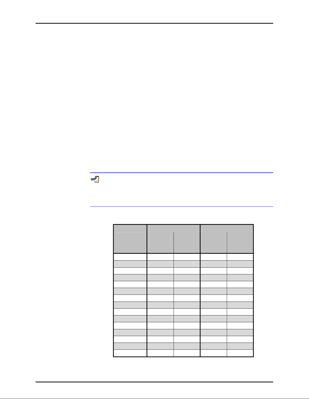
Table 1. Reference Pressure Transducer (Q-RPT) Designations and Ranges
SI VERSION US VERSION
RPT
DESIGNATION
A10M1 10 000 10 000 1 500 1 500
A7M1 7 000 7 000 1 000 1 000
A3.5M1 3 500 3 500 500 500
A2M1 2 000 2 000 300 300
A1.4M1 1 400 1 400 200 200
A700K1 700 700 100 100
A350K1 350 250 50 35
A200K1 200 100 30 15
A160K 1 160 60 23 8
A100K1 110 10 16 1.5
BA100K4 110 - - 16 - -
G200K2 - - 200 - - 30
G100K2 - - 100 - - 15
G15K2 - - 15 - - 2.2
BG15K3 - - ±15 - - ±2.2
1. All AXXXX RPTs support absolute, gauge and compound (negative) gauge modes.
2. All GXXXX RPTs are positive gauge mode only.
3. BG15K is bi-directional gauge from - 15 to + 15 kPa (- 2.2 to + 2.2 psi).
4. BA100K is a barometric range whose low point is 70 kPa absolute (10 psi).
MAXIMUM
PRESSURE
Absolute
[kPa]
MAXIMUM
PRESSURE
Gauge
[kPa]
MAXIMUM
PRESSURE
Absolute
[psi]
MAXIMUM
PRESSURE
Gauge
[psi]
© 2002-2007 DH Instruments, a Fluke Company Page 2
Page 13

1. INTRODUCTION
Warm Up Time
Resolution
Compensated Temperature Range
Acceleration Affect
Allows operation at ± 20° from
significant effect
Predicted One Year Stability
1
Precision
2
Measurement Uncertainty3
Delivered Pressure Uncertainty4
1. Predicted Q-RPT measurement stability limit (k=2) over one year assuming regular use of AutoZero function. AutoZero
occurs automatically in gauge mode whenever vented, by comparison with barometric reference in absolute mode.
Absolute mode predicted one year stability without AutoZ is ± (0.005 % Q-RPT span + 0.005 % of reading).
2. Combined linearity, hysteresis, repeatability. Add + 1 Pa (0.00015 psi) in gauge mode with an Axxx (absolute) Q-RPT for
the resolution and short term stability of the on-board barometer.
3. Maximum deviation of the Q-RPT indication from the true value of applied pressure including precision, predicted one year
stability limit, temperature effect and calibration uncertainty, combined and expanded (k=2) following the ISO “Guide to the
Expression of Uncertainty in Measurement.”
4. Maximum deviation of the PPC3 controlled pressure from the true value including measurement uncertainty and dynamic
control hold limit.
5. % of reading value times measured pressure from 100 to 30 % of Q-RPT span. Under 30 % of Q-RPT span, % of reading
value times 30 % of Q-RPT span. For example, if the Q-RPT is a Standard A160K, the Measurement Uncertainty in
pressure is 0.010% times the measured pressure to 48 kPa (160 kPa span x 30%) and 0.0048 kPa (160 kPa span x 30%
x 0.01%) under 48 kPa.
6. % of reading value times measured pressure from 100 to 30 % of AutoRanged span. Under 30% of AutoRanged span, %
of reading value times 30% of AutoRanged span. If AutoRanged span is less then 30% of maximum Q-RPT span, % of
reading values times measured pressure, or % of reading times 9% of Q-RPT span, whichever is greater. For example, if
the Q-RPT is a Premium A160K and AutoRanged span is 160 kPa, the Measurement Uncertainty in pressure is measured
pressure x 0.008% to 48 kPa (160 kPa AutoRanged span x 30%) and 0.0038 kPa (160 kPa span x 30% x 0.008%) under
48 kPa. If the AutoRanged span is 100 kPa (greater than 30% of 160 kPa maximum Q-RPT span), the measurement
uncertainty in pressure is measured pressure x 0.008% to 30 kPa (100 kPa AutoRanged span x 30%) and 0.0024 kPa
(100 kPa span x 30% x 0.008%) under 30 kPa. If the AutoRanged span is 30 kPa (less than 30% of the 160 kPa
maximum Q-RPT span), the measurement uncertainty in pressure is measured pressure x 0.008% to 14.4 kPa (160 kPa
maximum Q-RPT span x 9%) and 0.0012 kPa (160 kPa maximum Q-RPT span x 9% x 0.008%) under 14.4 kPa.
None required, 30 minute temperature stabilization
recommended for best performance from cold power up.
To 1 ppm, user adjustable
5 to 35 °C
± 0.008 % /g maximum, worst axis
Allows operation at ± 20° from reference plane without
significant effect
± 0.005% of reading
STANDARD CLASS PREMIUM CLASS
± 0.008% of reading or
0.0024% of Q-RPT span,
whichever is greater
5
± 0.01% of reading or 0.0030%
of Q-RPT span, whichever is
greater
5
± 0.011 % of reading or
0.0033% of Q-RPT span,
whichever is greater
5
± 0.005% of reading, 0.0015%
of AutoRanged span, or
0.0005% of Q-RPT span,
whichever is greater
± 0.008 % of reading, 0.0024%
of AutoRanged span, or
0.0007% of Q-RPT span,
whichever is greater
± 0.009 % of reading,
0.0027% of AutoRanged span,
or 0.0008% of Q-RPT span,
whichever is greater
6
6
6
Page 3 © 2002-2007 DH Instruments, a Fluke Company
Page 14
PPC3™ OPERATION AND MAINTENANCE MANUAL
1.2.2.2 UTILITY SENSOR
Base PPC3 pressure controllers include a utility sensor. If a Hi Q-RPT
(see Section 3.2.4) is installed, there is no utility sensor.
Utility sensors are used for pressure control, system monitoring and safety functions.
They are intended for indication only, not to provide reference pressure
measurement. Q-RPTs (see Section 1.2.2.1) are used for reference measurement.
Warm Up Time
Range
Resolution
Precision
1.2.2.3 ON-BOARD BAROMETER
The on-board barometer is used only to measure changes in atmospheric
pressure to provide dynamic compensation of the Q-RPT’s atmospheric pressure
offset when using an Axxx (absolute) Q-RPT to make gauge pressure
measurements.
Warm Up Time
Resolution
Precision
Predicted Stability
Range
None required
PPC3-10M: 10 MPa (1 500 psi) absolute and gauge
PPC3-7M: 7 MPa (1 000 psi) absolute and gauge
PPC3-2M: 2 MPa (300 psi) absolute and gauge
PPC3-700K: 700 kPa (100 psi) absolute and gauge
PPC3-200K: 300 kPa (45 psi) absolute;
200 kPa (30 psi) gauge
0.001 % of span
0.1 % of span
None required
70 to 110 kPa (10 to 16 psi)
0.001 % of span
0.1 % of span
0.05 kPa/yr (0.008 psi/yr)
The on-board barometer is only present in PPC3s that have an Axxx
(absolute) or BGxxx (bi-directional gauge) internal Q-RPT.
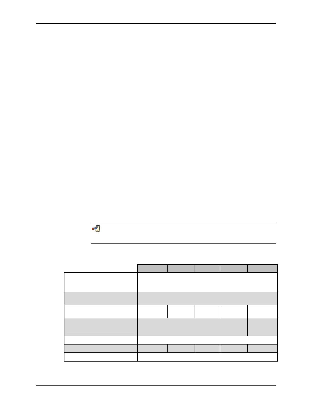
1.2.3 PRESSURE CONTROL SPECIFICATIONS
Control Precision
Lowest Controllable Pressure
(gauge mode)
Lowest Controllable Pressure
(absolute, negative gauge modes)
Ultimate Pressure
(absolute, negative gauge)
Typical Pressure Setting Ready Time
Optimum TEST Volume
Default Dynamic Control Hold Limit
* Control precision is reduced in absolute mode under 7 kPa (1 psi) absolute.
PPC3-200K PPC3-700K PPC3-2M PPC3-7M PPC3-10M
± 0.002 % of reading or of 2 % of controller span, whichever is greater.*
Q-RPT used must provide resolution higher than expected
Zero set by automated venting. Lowest point above or below zero
limited only by Q-RPT resolution and control precision.
1.5 kPa
(0.2 psia)
TEST(+) port is isolated and connected to vacuum
supply. Typically < 50 Pa (0.008 psia) depending on
vacuum source and test volume configuration.
500 cc 500 cc 500 cc 250 cc 250 cc
3 kPa
(0.4 psia)
control precision.
5 kPa
(0.75 psia)
15 to 30 seconds.
± 0.005 % of current range
5 kPa
(0.75 psia)
10 kPa
(1.5 psia)
5 kPa
(0.75 psia)
© 2002-2007 DH Instruments, a Fluke Company Page 4
Page 15
2. INSTALLATION
.
22.
I
NNSSTTAALLLLAATTIIOON
I
N
2.1 UNPACKING AND INSPECTION
2.1.1 REMOVING FROM PACKAGING
PPC3 is delivered in a corrugated container with high density polyethylene inserts to hold it in
place; or in the optional molded, medium density polyethylene shipping case with a custom
foam insert.
Remove the PPC3 and its accessories from the shipping container and remove each element
from its protective plastic bag.
2.1.2 INSPECTING CONTENTS
Check that all items are present and have no visible damage.
A standard PPC3 includes all items indicated in Table 2.
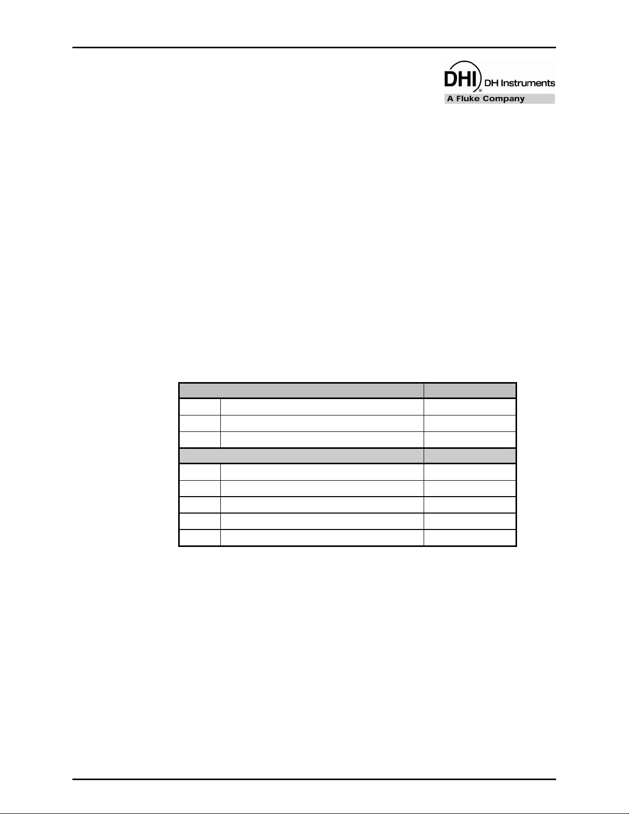
Table 2. PPC3 Packing List
DESCRIPTION PART #
1 ea. PPC3 Pressure Controller/Calibrator FAM007
1 ea. Calibration Report 550100
1 ea. Test Report 550200
ACCESSORIES: 401918 (401918-CE)
1 ea. Operation and Maintenance Manual 550128
1 ea. Power Cord (7.5 ft.) 100770 (100770-CE)
1 set (6) Rubber Feet Caps 400203
1 ea. Drivers Connector 401382
1 ea. General Accessories Disk (white CD) 102987
Page 5 © 2002-2007 DH Instruments, a Fluke Company
Page 16

PPC3™ OPERATION AND MAINTENANCE MANUAL
2.2 SITE REQUIREMENTS
The PPC3 can be installed on any flat, stable surface at a convenient height. The front feet can be
extended so that the unit can be inclined slightly for easier viewing. The PPC3 can also be mounted in a
standard 19 in. rack using the optional rack mount kit.
Minimizing the distance between the PPC3 and the device or system under test will enhance control
performance and reduce pressure setting times.
Ready access to the PPC3 rear panel should be considered to facilitate making and breaking
pressure connections.
Pneumatic and RS-232 connections to RPM4s should be considered if RPM4s are to be used as
external reference pressure measurement devices (see Section 2.3.7).
The Self Purging Liquid Trap (SPLT), if used, should be mounted vertically at the low point of the
connection between the PPC3 TEST(+) port and the test (see Section 2.3.8.1).
If you are using a G15K or BG15K Q-RPT with a Dual Volume Unit (DVU), its location and
connections should be considered (see Section 2.3.8.2).
Support facilities required include:
• An electrical power source of 85 to 264 VAC, 50 - 60 Hz.
• A continuous, regulated pressure supply of clean, dry, non-corrosive gas at PPC3 maximum
control pressure + 10 % (at least 70 kPa (10 psi) in the case of a BG15K Q-RPT) to be connected to
the PPC3 SUPPLY port. Lower gas pressure supply can be used but should exceed the maximum
desired test output pressure by 10 to 20 %.
• A vacuum source of less than 1 psia (7 kPa) and with displacement of at least 3 cfm (90 lm)
if control of pressures under 3 psi (20 kPa) gauge is desired.
2.3 SETUP
2.3.1 PREPARING FOR OPERATION
To prepare PPC3 for check out and operation:
Remove the plastic caps from the PPC3 rear panel pressure connections.
Remove the protective plastic sheet from the front panel display.
Install the rubber feet caps onto the bottom case feet, if desired.
Familiarize yourself briefly with the front and rear panel (see Section 2.3.2).
Then proceed with Sections 2.3.3 to 2.3.11
© 2002-2007 DH Instruments, a Fluke Company Page 6
Page 17
2. INSTALLATION
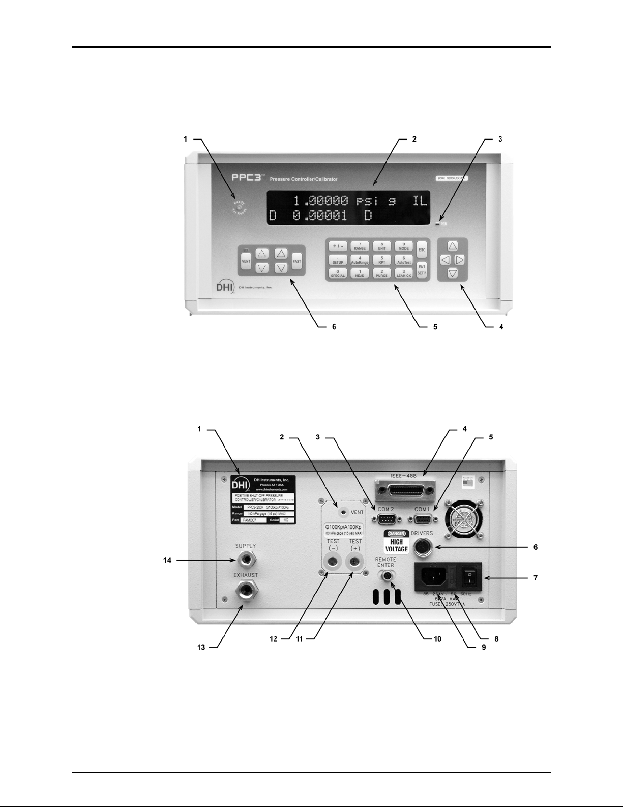
2.3.2 FRONT AND REAR PANELS
2.3.2.1 FRONT PANEL
1. Ready/Not Ready Indicator
2. Display
3. Remote Activity Indicator
Figure 1. Front Panel
4. Cursor Control Keys
5. Multi-Function Keypad
6. Direct Pressure Control Keys
2.3.2.2 REAR PANEL
1. Label, Product
2. VENT port
3. COM2 Connector
4. IEEE-488 Connector
5. COM1 Connector
6. Drivers (12 V) Connector
7. Power Switch
Figure 2. Rear Panel
8. Fuse
9. Electrical Power Connector (IEC-320-C13)
10. Remote [ENT] Connector
11. Pressure Connection, TEST(+)
12. Pressure Connection, TEST(-)
13. Pressure Connection, EXHAUST
14. Pressure Connection, SUPPLY
Page 7 © 2002-2007 DH Instruments, a Fluke Company
Page 18

PPC3™ OPERATION AND MAINTENANCE MANUAL
2.3.3 POWER CONNECTION
Check that the PPC3 power switch is OFF.
Connect the supplied power cable to the rear panel power module.
Connect the other end of the power cable to an electrical supply of 85 to 264 VAC, 50/60 Hz.
2.3.4 REMOTE [ENTER/SET P] CONNECTION (FOOTSWITCH OR OTHER SWITCH)
Connect the optional remote ENTER footswitch, if available or a user supplied switch fitted to
the optional cable (see Section 7.3). Connect the cable to the PPC3 rear panel connection
labeled REMOTE ENTER. Activating the switch is equivalent to pressing the [ENT/SET P]
key on the front panel (see Section 3.1.4).
2.3.5 CONNECTING TO A PRESSURE SUPPLY (SUPPLY PORT)
Using a pressure connecting hose or tube of appropriate pressure rating, connect the
pressure supply to the SUPPLY port on the rear panel of PPC3. The PPC3 SUPPLY port
connection is 1/8 in. NPT female.
The supply pressure should be equal to the maximum PPC3 control pressure + 10 % (or at
least 70 kPa (10 psi) for a BG15K Q-RPT). Lower gas pressure sources can be used but
should exceed the maximum desired test output pressure by 10 to 20 %.
Never connect a pressure supply greater than 20 % over the maximum control pressure of
the PPC3 model you are using (except models with a BG15K Q-RPT only). Be sure to
connect the pressure supply to the SUPPLY port. Connecting to another port is likely to
damage PPC3.
2.3.6 CONNECTING A VACUUM PUMP (EXHAUST PORT)
For PPC3 to set pressures under atmosphere and/or to reliably set pressure under 20 kPa (3 psi)
gauge (other than zero gauge), a vacuum supply must be connected to the EXHAUST port.
Never connect a pressure supply to or plug the PPC3 EXHAUST port.
To avoid building up pressure on the EXHAUST port or on a vacuum pump connected to
the EXHAUST port, the vacuum source should either be continuously ON or the EXHAUST
port should be bypassed to atmosphere when the vacuum source is OFF. This is because
when a supply pressure is applied to the PPC3 SUPPLY port and the PPC3 is NOT in the
vent ON condition, there may be a constant gas exhaust through the PPC3 EXHAUST port.
To assure optimum pressure control when changing the pressure applied to the EXHAUST
port from vacuum to atmosphere or vice-versa, be sure to change the control reference
setting if the setting is NOT in AUTO mode (see Section 3.5.7.2).
© 2002-2007 DH Instruments, a Fluke Company Page 8
Page 19

2. INSTALLATION
2.3.7 CONNECTING EXTERNAL Q-RPTS IN RPM4 REFERENCE PRESSURE MONITORS
PPC3 can be connected pneumatically and by RS-232 to one or two RPM4 reference
pressure monitors to use up to four external Q-RPTs (two in each RPM4) as external
reference pressure measurement devices (see Section 3.2.4).
The PPC3 then manages communications and other RPM4 functions to integrate the RPM4
measurement capabilities into the PPC3 system. The RPM4 Q-RPT module’s Self Defense
System (SDS) is used to shut-off RPM4 Q-RPTs from the pressurized system when they are
not in use (see the RPM4 Operation and Maintenance Manual).
As a general rule, making the pneumatic connection between the PPC3 TEST port and the
remote Q-RPT as direct as possible favors good pressure control. As distance, volumes
and restrictions between the PPC3 TEST port and the remote Q-RPT are added, the
possibility of difficulty with pressure control when using the external Q-RPT increases.
To connect a PPC3 to an RPM4 to be used as part of the PPC3 system proceed as follows:
Set up the RPM4 for use as an external device to PPC3 following the instructions in
the RPM4 Operation and Maintenance Manual, Using RPM4 With a PPC3
Controller/Calibration Section.
Using tubing of appropriate pressure rating and a Tee, connect the RPM4 Q-RPT
TEST(+) port to the PPC3 TEST(+) port. The third leg of the Tee is for the connection to
the device or system under test. If there are two RPM4s, Tee the second RPM4 in series
with the first one. The order of the RPM4s on the test line is not relevant.
If an RPM4 Q-RPT will be used in a gauge pressure range of less than 100 kPa (15 psi),
consider connecting the RPM4 Q-RPT module TEST(-) port to the PPC3 TEST(-) port and
to the “low” connection of the DUT if available. This will improve pressure control and
stability when ambient pressure is unstable. If the Q-RPT is an Axxx designation Q-RPT,
this connection should be made but also be left open to atmosphere.
When external Q-RPTs are used with PPC3, the maximum set pressure is the maximum
pressure of the PPC3 controller/calibrator. The maximum pressure of the PPC3 is
determined by the PPC3 controller model or the Hi Q-RPT if one is installed (see Section 1.2.1).
Using a standard pin-to-pin DB-9M to DB-9F RS232 cable, connect COM2 of the PPC3
to COM1 of the RPM4 (see Section 4.2.1.3). If there are two RPM4s, connect COM2 of the
first RPM4 to COM1 of the second RPM4. The order of the RPM4 daisy chain is not
relevant.
Turn ON the PPC3 and RPM4(s).
Press [RPT] on the PPC3 key pad. This causes PPC3 to execute the Q-RPT search
function (see Section 3.3.5). Q-RPTs with whom communication is established will be
shown on the PPC3 display identified by their position (see Table 3).
Page 9 © 2002-2007 DH Instruments, a Fluke Company
Page 20

PPC3™ OPERATION AND MAINTENANCE MANUAL
For PPC3 to identify external RPM4s, the RPM4 COM1 port settings must be:
Baud rate: between 1200 and 19200
Parity: Even
Date bits: 7
Stop bits: 1
If PPC3 is not able to establish communications with RPM4s and their Q-RPTs, check
that the RPM4 COM1 port setting conform to the requirements above. If the COM1 port
settings are correct, check that the correct communications cable is being used
(standard pin-to-pin DB-9M to DB-9F RS232) and is connected to the correct
communications ports.
PPC3 COM2 > 1
st
See the RPM4 Operation and Maintenance Manual for additional information on RPM4
RS232 communications and COM port settings.
2.3.8 CONNECTING TO THE DEVICE UNDER TEST (TEST(+) AND TEST(-) PORTS)
RPM4 COM1; 1st RPM4 COM2 > 2nd RPM4 COM1
If you are using a self purging liquid trap (SPLT), see Section 2.3.8.1 before proceeding to
connect the device under test.
If the PPC3 has a G15K or BG15K Q-RPT, a dual volume unit (DVU) should be installed for
very low pressure control. See Section 2.3.8.2 before proceeding to connect to the device
under test.
Using a pressure connecting hose or tube of appropriate pressure rating, connect the device or
system to be tested to the PPC3 TEST(+) port. The PPC3 TEST(+) connection is 1/8 in. NPT female.
PPC3 TEST(+) AND TEST(-) PORTS
All PPC3s have a TEST(+) and a TEST(-) port. See Figure 13 for PPC3 internal Q-RPT
TEST port configurations.
The TEST(+) port is connected to Axxx (absolute) Q-RPTs and to the high side of Gxxx or
BGxxx (gauge, bi-directional gauge) Q-RPTs.
The TEST(-) port is connected to PPC3s internal barometer, if present, and to the low side of
Gxxx or BGxxx (gauge, bi-directional gauge) Q-RPTs.
• When operating in absolute mode: The TEST(-) port is left open to atmosphere.
• When operating in gauge or negative gauge mode with a range greater than 50 kPa
(7.5 psi): The TEST(-) port is normally left open to atmosphere. A possible exception is
when the device or system under test is in an ambient pressure that may differ significantly
from the ambient pressure around the PPC3. For example, if the PPC3 is controlling
pressure into DUTs in an environmental chamber, the pressure in the environmental
chamber may be different from ambient pressure around the PPC3. In this case,
connecting a tube from the TEST(-) port to the inside of the chamber may improve
measurement results. If the Q-RPT in use is an Axxx Q-RPT, this tube must be left open to
the environment so t hat the pressure inside cannot deviate too far from ambient. When using
an Axxx Q-RPT, if this tube is connected to t he lo w o r re f er en c e si d e of DU Ts , b e s ur e to
open to the local environment as well.
• When operating in gauge or negative gauge mode with a range less than 50 kPa (7.5 psi):
As a general rule, it is preferable to connect the PPC3 TEST(-) port(s) directly to the low or
reference side of the device under test to assure that these are at the same pressure.
When using an Axxx Q-RPT, this connection must also be open to atmosphere. When using
a Gxxx or BGxxx Q-RPT, it is preferable that this connection not be open to atmosphere.
© 2002-2007 DH Instruments, a Fluke Company Page 10
Page 21
2. INSTALLATION
Do not apply pressure to the TEST(+) port without having a pressure supply equal to or
greater than the applied pressure connected to the SUPPLY port. When controlling
pressure to the TEST(+) port externally, do not cause the pressure to change at a very
rapid rate. For example, do not vent suddenly by opening an external valve. Internal
damage to the PPC3 may result.
Do not connect a pressure supply to the TEST(-) port. The pressure applied to this port
should be maintained at atmospheric pressure (between 70 and 110 kPa (10 and 16 psia)).
Exceeding these limits may damage a Gxxx or BGxxx Q-RPT and/or the PPC3’s
on-board barometer.
Operating the PPC3 connected to a system with liquid contaminants without taking
proper precautions to purge the system and test line may cause contamination of the
PPC3 that will require non-warranty service.
Minimizing the length of the test connection tubing will enhance control performance and
reduce pressure setting time. For normal operation, the total volume of the device or
system under test including connecting tubing should be less than 1 000 cc (60 in
3
)
up to 2 000 kPa (300 psi) and less than 500 cc (30 in3) above 2 000 kPa (300 psi).
Minimizing the length of the test connection tubing and restrictions in connections will
enhance control performance and reduce pressure setting time.
PPC3 pressure control will not operate properly if there are excessive leaks in the test
system. In general, the maximum acceptable leak rate for optimal PPC3 automated pressure
control operation and to assure in tolerance measurements with default pressure control
parameters is ± 0.5 % of set pressure/minute. In DYNAMIC CONTROL mode, to handle
higher test system leak rates, increase the hold limit using CUSTOM CONTROL (see
Section 3.4.6.1).
PPC3 pressure control may be adversely affected if the test connection tubing is too
restrictive. For optimum results, the inner diameter of the connecting hose should be
> 1.75 mm (0.07 in.), or more.
2.3.8.1 INSTALLING A SELF PURGING LIQUID TRAP (SPLT)
The SPLT (optional) is intended to collect and exhaust liquid or other
contaminants that may be present in the device or system under test so that they
do not return to contaminate the PPC3.
The SPLT is installed in the TEST(+) connection line at a low point between
PPC3 and the device or system under test. If the PPC3 system includes external
Q-RPTs in RPM4(s), the RPM4s should be connected on the PPC3 side of the
SPLT.
See the SPLT Operation and Maintenance manual for more complete
instructions on SPLT installation.
Page 11 © 2002-2007 DH Instruments, a Fluke Company
Page 22

PPC3™ OPERATION AND MAINTENANCE MANUAL
2.3.8.2 INSTALLING A DUAL VOLUME UNIT (DVU), G15K AND
BG15K Q-RPTS
To achieve in tolerance pressure control with the very low range of the G15K and
BG15KQ-RPTs, a PK-PPC-BG-DVU dual volume units should be installed in-line
on the TEST(+) and TEST(-) ports. The DVU includes two thermally isolated
volumes installed in the test line to improve control stability.
See the PK-PPC-BG-DVU instruction sheet for additional information on its
installation.
2.3.9 THE VENT PORT
The PPC3 VENT port is the system vent to atmosphere point used to set zero gauge pressure as
well as to obtain Q-RPT measurements of atmospheric pressure. The PPC3 on-board
barometer, if present is connected to the VENT port. Though a pressure hose can be
connected to the VENT port to direct the vented gas flow, a completely unobstructed
connection to atmosphere must be maintained for PPC3 reference pressure measurements
to operate normally.
The PPC3 VENT port fitting is 10-32 UNF.
NEVER plug, obstruct or connect a supply pressure to the PPC3 VENT port. This may
adversely affect GAUGE mode operation and AutoZeroing functions.
2.3.10 CHECK/SET SECURITY LEVEL
PPC3 has a security system based on user levels. By default, the security system is set to
“low”, which includes certain access restrictions, and there is no password required to
change the security level. See Section 3.5.5.5 for information on the security level system.
As part of the PPC3 startup, determine the security level that is appropriate for the PPC3 and
set a password if desired.
PPC3 is delivered with the security level set to “low” to avoid inadvertent altering of critical
internal settings but with access to changing security levels unrestricted. It is recommended
that the low security level be maintained at all times and password protection be
implemented if control over setting of security levels is desired.
2.3.11 TURN OFF ABSOLUTE AND NEGATIVE GAUGE MODE (AXXX RPT)
If your PPC3 has an Axxx (absolute) Q-RPT, it is able to operate in gauge,
negative gauge and absolute measurement modes (see Section 3.3.3).
If the PPC3 will be used only in gauge mode, the other measurement modes can
be turned off so they are no longer accessible. This can avoid confusion and/or
accidental use of the wrong measurement mode. See Section 5.2.5 for complete
information on turning off absolute and negative gauge measurement modes.
© 2002-2007 DH Instruments, a Fluke Company Page 12
Page 23

2. INSTALLATION
2.4 POWER-UP AND VERIFICATION
2.4.1 SWITCH POWER ON
Actuate the power switch on the PPC3 rear panel. Observe the front panel display as PPC3
initializes, error checks and goes to the MAIN RUN screen (see Section 3.1.1).
PPC3 power-up condition is Internal, Hi Q-RPT or utility sensor active, VENT ON unless the
pressure measured by the Hi Q-RPT is more than 20 kPa (3 psi) away from standard
atmospheric pressure.
If the PPC3 fails to reach the MAIN RUN screen, service is required. Record the sequence
of operations and displays observed.
2.4.2 CHECK PRESSURE MEASUREMENT OPERATION
2.4.2.1 CHECKING ABSOLUTE MODE PRESSURE MEASUREMENT
If the PPC3 has an Axxx (absolute) Q-RPT or a utility sensor (IuH), check that it
operates properly in absolute mode.
If the PPC3 is not vented (VENT LED OFF), press the [VENT] direct pressure
control key to vent the PPC3 (VENT LED ON) (see Section 3.1.3).
Using the [RANGE] function key to change ranges if necessary and select the
Axxx (absolute) Q-RPT DF range (see Section 3.3.1). Press the [MODE]
function key and select <absolute> mode (see Section 3.3.3). Use [UNIT] to
change the pressure unit if desired (see Section 3.3.2).
Observe the current value of atmospheric pressure. Check that the value agrees
with the local value of atmospheric pressure. Repeat this process for all the
Axxx (absolute) Q-RPTs and or the utility sensor in the PPC3 system. Check
that the values of atmospheric pressure measured by the different devices agree
with each other within PPC3 or RPM4 measurement tolerances as applicable
(see Section 1.2.2.1, 1.2.2.2). If they do not agree within tolerances, the PPC3
or RPM4 Q-RPT may need calibration or repair.
2.4.2.2 CHECKING GAUGE MODE PRESSURE MEASUREMENT
If the PPC3 is not vented, press the [VENT] direct pressure control key to vent it
(see Section 3.1.3).
Press the [MODE] function key and select <gauge> mode. Change the
pressure unit if desired (see Section 3.3.3).
Observe that, within ten seconds, zero is indicated. It is normal for PPC3 to indicate
a value other than zero for up to ten seconds when first entering gauge mode.
Using the [RANGE] function key to change ranges, observe that zero is
indicated for each Q-RPT within 10 seconds. It is normal for PPC3 to indicate a
value other than zero when vented when gauge mode is first entered or ranges
are changed. After about ten seconds, the VENT LED should flash and zero
should be indicated. If this does not occur, check that the AUTOZERO function
is O N (see Section 3.5.1). If AUTOZERO is ON and the displayed pressure will not
zero when vented in gauge or bi-directional gauge measurement mode, PPC3 may
need repair.
Page 13 © 2002-2007 DH Instruments, a Fluke Company
Page 24

PPC3™ OPERATION AND MAINTENANCE MANUAL
2.4.3 LEAK CHECK
If desired, perform a leak check of the test system (see Section 3.3.9).
2.4.4 PURGE
If an SPLT is included and installed in the test line and the Device Under Test (DUT) may be
contaminated with liquids, perform a purge of the DUT (see Section 3.3.8). The PURGE function
must first be activated (see Section 3.5.7.4). This will rid the DUT of contaminating liquids.
Operating the PPC3 connected to a system with liquid contaminants without taking
proper precautions to purge the system and test line may cause contamination of the
PPC3 that will require non-warranty service.
2.4.5 CHECK PRESSURE CONTROL OPERATION
Select a pressure range using [RANGE] (see Section 3.3.1).
Press [SETUP], <6control>, <2dynamic> (see Section 3.4.6). Then [ESC] back to the
MAIN RUN screen.
Press [ENT]. Key in a target pressure within the active range and press [ENT] again
(see Section 3.3.10).
Verify the maximum pressure rating of the system connected to the PPC3 TEST(+) port
before entering a target pressure. Do not enter a target pressure greater than the
pressure rating of the system connected to the PPC3 TEST(+) port.
PPC3 should set the target pressure and indicate Ready (see Section 3.2.2) continuously in
15 to 60 seconds. If it does not, see Section 6 to troubleshoot.
2.5 SHORT TERM STORAGE
The following procedure is recommended for short term storage of PPC3:
Vent the PPC3 test pressure.
Turn the power OFF using the rear panel power switch.
Shut OFF or disconnect the pressure supply.
Shut OFF or disconnect the vacuum supply. Be sure the pressure supply is disconnected or the
vacuum pump is bypassed from the PPC3 EXHAUST port before turning OFF the vacuum pump.
© 2002-2007 DH Instruments, a Fluke Company Page 14
Page 25

3. OPERATION
.
33.
O
PPEERRAATTIIOON
O
N
3.1 USER INTERFACE
PPC3 is designed to offer a practical balance between simple, straight forward operation and
the availability of a wide variety of advanced functions with a high level of operator discretion.
The local operator interface is through a 2 x 20 display, a function/data keypad, a cursor
control pad and direct pressure control keys.
Remote communication is by RS232 (COM1) or IEEE-488. See Section 4 for specific
information on remote communication.
3.1.1 MAIN RUN SCREEN
The PPC3 MAIN RUN screen is its home display that is reached on power-up and from which
other functions and menus are accessed. It is the very top level of all menu structures.
The MAIN RUN screen is where the operator works with PPC3 to set and read pressures.
It provides complete information on the system’s current configuration and operating status.
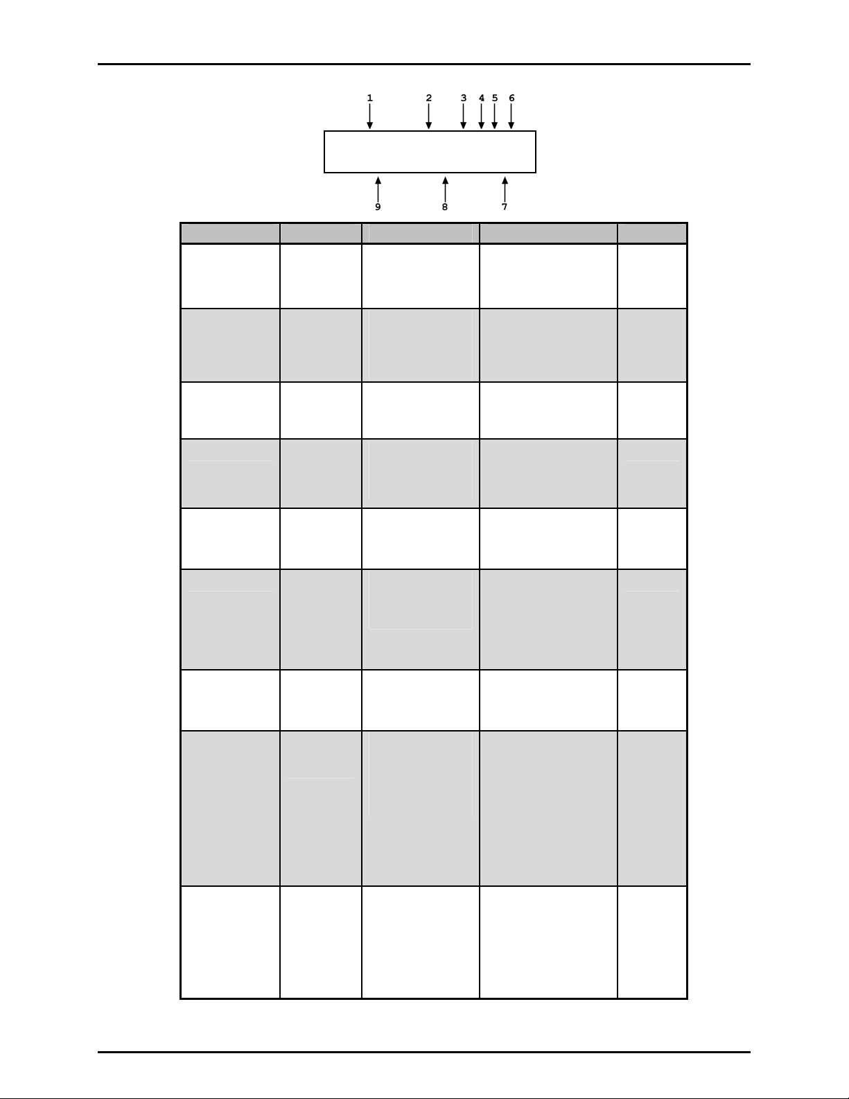
Figure 3 and its legend table summarize the PPC3 MAIN RUN screen fields and their functions.
PPC3 has a screen saver function which causes the display to dim if no key is pressed for
10 minutes. Pressing a key restores full power to the display. The screen saver time can
be changed or screen saving can be completely suppressed (see Section 3.5.5.1).
Page 15 © 2002-2007 DH Instruments, a Fluke Company
Page 26
PPC3™ OPERATION AND MAINTENANCE MANUAL
PRESSURE1UNITM hzRRH
TPRESSURE2 CC NN/NN
DISPLAY FIELD NAME PURPOSE CONTENTS SECTION
1. PRESSURE1 Measured
pressure
Displays pressure
measured by active
Q-RPT
Numerical pressure
value and sign
1.2.2.1
1.2.2.2
3.3.10
2. UNIT Unit of
measure
Identifies pressure
unit of measure in
Pressure unit of
measure abbreviation
3.3.2
which PRESSURE1
and PRESSURE2
are displayed
3. M Measurement
mode
4. h Head
pressure
indicator
5. z AutoZero
indicator
Identifies
measurement mode
of displayed pressure
Indicates whether a
fluid head correction
is applied to
PRESSURE1
Indicates whether
the AutoZero
function is ON or
<a>: absolute
<g>: gauge or
negative gauge
<h>: the fluid head
is not zero
<blank>: fluid head is
zero
<z>: AutoZ is ON
<blank>: AutoZ is OFF
3.3.3
3.3.7
3.5.1
OFF
6. RRH Active QRPT position
indicator
Indicates the position
of the active utility
sensor or Q-RPT in
the PPC3 system
<IH>: Internal Hi
3.2.4
<IuH>: Internal Hi
(utility sensor)
<X1H>: External 1 Hi
<X1L>: External 1 Lo
<X2H>: External 2 Hi
<X2L>: External 2 Lo
7. NN/NN Sequence
progress
indicator
Indicates progress of
an ATest sequence,
during test execution
<NN/NN>: Number of
this point over total
number of points in the
3.3.6
sequence
8. CC Pressure
control
indicator
Indicates type of
pressure control,
whether control is
currently active and
whether custom
control limits are in use
<D>: Control mode is
dynamic
<S>: Control mode is
static
<C> is appended to the
<D> or <S> if control
3.2.1
3.4.6
limits are custom
Control character(s)
flash if PPC3 is actively
controlling
9. TPRESSURE2 Pressure
information
indicatior
Pressure indication
depending on current
PPC3 function.
Leading character
identifies the value.
<R>: Pressure rate of
change in current
pressure unit/second
<T>: Pressure control
target
3.3.10
<D>: Deviation from the
pressure control
target
Figure 3. MAIN RUN Screen Display Fields
© 2002-2007 DH Instruments, a Fluke Company Page 16
Page 27
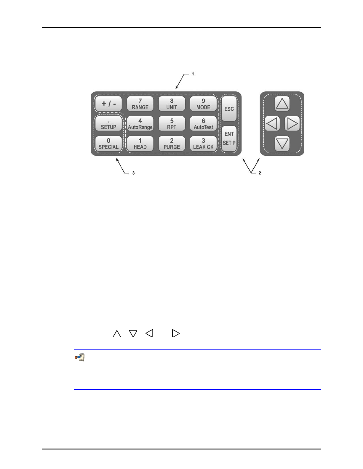
3. OPERATION
3.1.2 FUNCTION / DATA KEYPAD LAYOUT AND PROTOCOL
The PPC3 has a function/data keypad for local operator access to direct functions, function
menus and for data entry.
1. The Function/Data keys allow very commonly
used functions to be accessed directly by a
single keystroke when pressed from the
MAIN RUN screen (see Section 3.2.7). The
name of the function is on the bottom half of
the key. These keys enter numerical values
when editing.
2. The Editing and Execution keys are for
starting and suspending command execution,
cursor control in menus and editing entries.
Figure 4. Keypad Layout
3. The Menu/Data keys provide access to
function menus when pressed from the
MAIN RUN screen. The menu name is on
the bottom half of the key. The SETUP menu
is for more frequently used functions (see
Section 3.4). The SPECIAL menu is for
functions that are not generally used as a
part of day to day operation (see Section
3.5). These keys enter numerical values
when editing.
Pressing the [ENT/SET P] key generally causes execution or forward movement in the menu
tree. Pressing [ENT/SET P] from the MAIN RUN screen allows an automated pressure
control command to be given.
Pressing the [ESC] key moves back in the menu tree and/or causes execution to cease or
suspend. Pressing [ESC] repeatedly eventually returns to the MAIN RUN screen and, from
there, allows momentary viewing of the PPC3 introduction screen.
Pressing the [+/-] key changes a numerical sign when editing. It also toggles through
multiple screens when available and is a shortcut to a momentary display of the active
RANGE from the MAIN RUN screen.
Pressing the [
], [ ], [ ] and [ ] keys allows reverse, forward and up, down cursor
movement when editing data entry or moving in menus.
Some screens go beyond the two lines provided by the display. This is indicated by a
flashing down arrow in the second line of the display. Press the cursor control keys to
move the cursor to access the lines that are not visible or directly enter the number of
the hidden menu choice if you know it.
Page 17 © 2002-2007 DH Instruments, a Fluke Company
Page 28
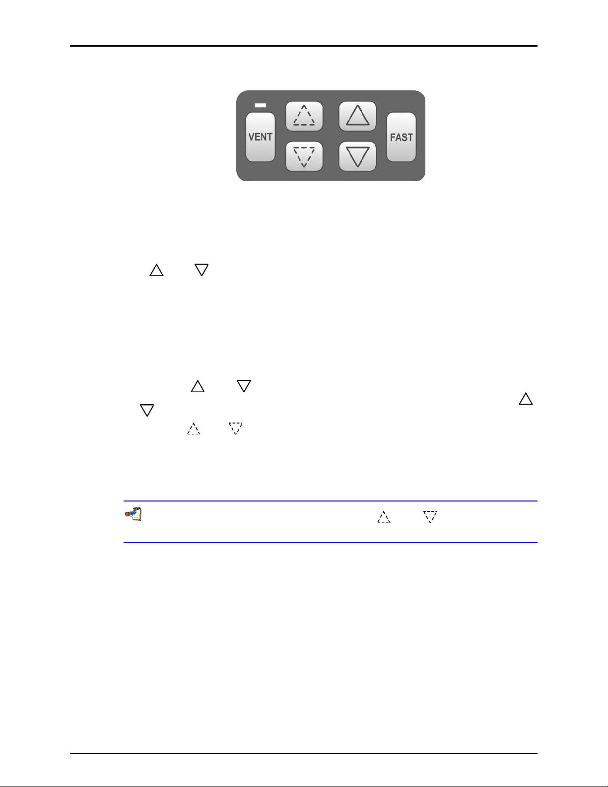
PPC3™ OPERATION AND MAINTENANCE MANUAL
3.1.3 DIRECT PRESSURE CONTROL KEYS
Figure 5. Direct Pressure Control Keys
The direct pressure control keys provide direct manual control of pressure increase,
decrease, jog and vent. They can be useful in adjusting pressure when automated pressure
control to a target value is not needed. The jog keys are also used to adjust the target
pressure during active pressure control.
The [
] and [ ] direct pressure control keys interrupt and override automated pressure
control.
Pressing the [VENT] key causes PPC3 to control pressure to near atmospheric pressure and
then open the system vent valve (see Figures 12 and 13). On-going execution of the vent
function is indicated by lighting a RED LED just above the [VENT] key. Completion of the
vent process is indicated by the Ready/Not Ready indicator light becoming GREEN with the
vent RED LED still lighted. The vent valve remains open until the [VENT] key is pressed
again, another direct pressure control key is pressed, or an automated pressure control
command is given.
Pressing the [
decrease at the slow slew rate. Holding the [FAST] key pressed while pressing the [
] key causes the pressure increase or decrease speed to change from slow to fast.
or [
Pressing the [
] and [ ] direct pressure control keys causes pressure to increase or
]
] and [ ] direct pressure control keys causes the pressure to jog or step by
a fixed amount. During active pressure control, they cause the target pressure to be
changed by the fixed amount. One press causes one step. The approximate value of the step
is set automatically depending on the current active PPC3 range. The value can be adjusted
using [SETUP], <3jog> or pressing both the up and down jog keys simultaneously (see
Section 3.4.3).
Pressing the up and down pressure jog keys ([ ] and [ ]) simultaneously is a
shortcut to the jog step size adjustment menu.
3.1.4 REMOTE [ENT/SET P] FOOTSWITCH
The optional remote ENTER function is a switch that duplicates the function of the front panel
[ENT] key. The remote ENTER function is serviced by a connector on the PPC3 rear panel
labeled REMOTE ENTER. An optional footswitch is available to activate remote entry hands
free or a user supplied switch may be used. See Section 7.3 for information on remote
ENTER switch wiring.
The remote ENTER feature can be particularly convenient when running AutoTests
(see Section 3.3.6) in which using a footswitch to [ENT] allows hands free operation.
© 2002-2007 DH Instruments, a Fluke Company Page 18
Page 29

3. OPERATION
3.1.5 SOUNDS
PPC3 is equipped with a variable frequency tone device to provide audible feedback and
alarms. The beeper is used for the following indications.
Valid key press Brief beep. Choice between three frequencies
or NO sound is available (see Section 3.5.5.2).
Invalid key press Descending two tone “blurp”.
Leak check completed Three two second beeps (see Section 3.3.9).
Upper or lower limit exceeded Intermittent one second beeps (see Section 3.4.4)
External device not connected Eight second high frequency beep (see Section
2.3.7)
Pmax! (overpressure limit) exceeded Eight second high frequency beep (see Section
3.4.4.1).
AutoTest reading in tolerance/out of Ascending triad/descending triad (see Section
tolerance reading 3.3.10).
3.2 GENERAL OPERATING PRINCIPLES
3.2.1 AUTOMATED PRESSURE CONTROL
PPC3 automated pressure control provides automated adjustment and control of pressure to
a user designated target value. Pressing [ENT/SET P] from the MAIN RUN screen allows a
pressure control target value to be entered and executed. Pressing [ESC], a direct pressure
control key or a function key causes active pressure control to be interrupted. Sending a
remote command when in local mode also interrupts pressure control.
PPC3 supports two pressure control modes to meet different pressure setting and controlling
requirements: dynamic and static. Pressure control parameters for each control mode are
automatically set to optimal default values for the operating PPC3 range when the range is
selected or AutoRange is used (see Section 3.3.4). Control parameters can be customized
using the [SETUP], <6control> function (see Section 3.4.6).
Control parameters:
Target Value The pressure setpoint specified by the operator.
Hold Limit A symmetrical positive and negative limit around the target value within
which the controlled pressure is maintained.
Stability Limit A rate of change of pressure limit in units of pressure/second used as a
criterion for the Ready/Not Ready condition in static control or when
See this section, Dynamic Control and Static Control for a detailed explanation of each
control mode and its advantages, the default control parameters and the control
customization options.
PPC3 is idle (control not active).
Dynamic Control
Dynamic control mode is designed to set the pressure to the target value and control
continuously to keep pressure within the hold limit and as close to the target value as possible
(see Figure 6). The advantage of this control mode is that the final pressure achieved is the
same as the target value. The maximum value of the control error is equal to the hold limit. The
average value of the control error is generally much smaller than the hold limit.
Page 19 © 2002-2007 DH Instruments, a Fluke Company
Page 30
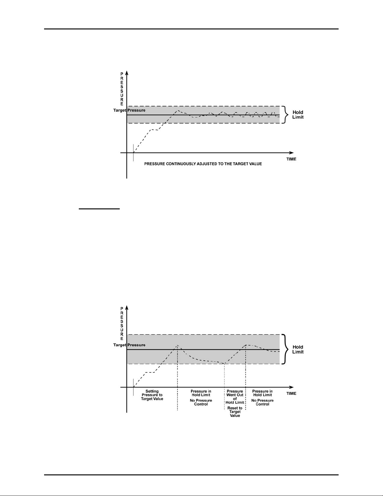
PPC3™ OPERATION AND MAINTENANCE MANUAL
During dynamic pressure control, the hold limit is active. If the pressure goes outside of the
hold limit, a Not Ready condition occurs. See Tables 6 and 7 for default hold limit values and
Section 3.3.6 to customize the hold limit.
Figure 6. Dynamic Pressure Control Operation
Static Control
Static control mode is designed to set the pressure near the target value and then interrupt
active control to allow pressure to stabilize naturally within the hold limit. The advantage of
this control mode is that pressure can be set and/or measured within a defined limit of a
target without interference from the pressure control system. In a system without excessive
leaks, the pressure stability achieved may be greater than the stability with which the
pressure control system can actively control pressure. Using static control to control
pressure near the desired set point and then measuring back the stabilized pressure without
interference of the control function can allow control errors to be completely eliminated.
However, the final pressure achieved is not equal to the target value.
During static pressure control, the hold limit is active. If the pressure goes outside of the hold limit,
a Not Ready condition occurs (see Section 3.2.2) and pressure is readjusted to the target value
(see Tables 6 and 7 and Section 3.3.6 for setting the hold and stability limits to user defined values).
Figure 7. Static Pressure Control Operation
© 2002-2007 DH Instruments, a Fluke Company Page 20
Page 31

3. OPERATION
3.2.2 PRESSURE READY/NOT READY
There is a Ready/Not Ready indication LED on the PPC3 front panel. This indication is
intended to provide the user with a clear and objective criterion for determining when a valid
pressure measurement can be made.
The Ready/Not Ready LED indications are:
<Green, no flash> Pressure Ready, control idle. PPC3 is NOT actively controlling the
pressure. This indicates no control is occurring and the pressure
stability is within the stability limit.
<Green, slow flash> Pressure Ready, control active. PPC3 is actively controlling the
pressure and the criteria for a Ready condition to occur have been met.
<Red > Pressure Not Ready. Either PPC3 is idle and pressure does not meet
the stability test or PPC3 is actively controlling the pressure and Ready
conditions have not yet been met. The control characters in the
middle of the second line of the display flash if control is active.
When pressure control is NOT active: A Ready condition occurs any time NO control
valve is operating and the pressure rate of change is inside the stability limit. The stability
limit is defined in terms of rate of change of pressure in current pressure units per second.
When pressure control is active: The criteria for determining the Ready/Not Ready
condition depend on whether the current control mode is static or dynamic. Pressure
Ready/Not Ready parameters are set by default when AutoRange is used, or a control mode
is selected. The parameters can be customized if desired (see Section 3.4.6).
Dynamic Control Ready/Not Ready
With dynamic pressure control active, a Ready condition occurs whenever:
• The current measured pressure is inside the hold limit.
In dynamic control mode, normal procedure is to assume that when a Ready condition
occurs (pressure inside the control hold limit), the measured pressure equals the target
pressure. For this reason, when the pressure is Ready in dynamic control mode, the
measured pressure display is equal to the target pressure.
Figure 8. Ready/Not Ready in Dynamic Pressure Control Mode
Page 21 © 2002-2007 DH Instruments, a Fluke Company
Page 32

PPC3™ OPERATION AND MAINTENANCE MANUAL
Static Control Ready/Not Ready
With static pressure control active a Ready condition occurs whenever:
• NO control valve is operating.
• The current measured pressure is at the target value within the hold limit.
• The rate of change of pressure is less than the current stability limit.
Figure 9. Ready/Not Ready in Static Control Mode
Ready/Not Ready When Not Actively Controlling
When NO automated pressure control is active, Ready is indicated whenever the
rate of change of pressure is less than the current stability limit (see Section
3.4.6.1).
3.2.3 GAUGE AND NEGATIVE GAUGE MODES WITH AN AXXX (ABSOLUTE) Q-RPT, DYNAMIC COMPENSATION FOR ATMOSPHERIC PRESSURE
Q-RPTs with the designation Axxx are intrinsically absolute but they are also used in gauge and
negative gauge measurement modes (difference from atmosphere) (see Section 3.3.3, PRINCIPLE).
Gauge measurement mode is achieved by subtracting the value of atmospheric pressure,
, from the Q-RPT’s absolute reading using AutoZ (see Section 3.5.1). In gauge or
P
offset,G
negative gauge measurement mode, the AutoZ routine that measures P
automatically whenever the PPC3 is in the vented condition. This assures the continuous
automated updating of the P
pres sure is the measured absolute pressure, P
value corresponding to atmospheric pressure. Gauge
offset,G
, minus the atmospheric offset.
u
P
gauge
= Pu - P
offset,G
However, atmospheric pressure can change between opportunities to run AutoZ and update
the value of P
, for example when running an extended test without venting. PPC3 uses
offset,G
dynamic compensation for atmospheric pressure to correct for these changes in
atmospheric pressure. When AutoZ executes, and P
PPC3’s on board barometer, P
change in atmospheric pressure, ΔP
the current barometer reading, P
execution, P
atm,0
:
, is also recorded. Later, when no longer vented, the
atm,0
, since P
atm
, and the barometer reading at the time of AutoZ
atm
= P
ΔP
atm
atm
was updated, is the difference between
offset,G
- P
atm,0
is determined, the reading of
offset,G
offset,G
, is run
© 2002-2007 DH Instruments, a Fluke Company Page 22
Page 33

3. OPERATION
Dynamic compensation for atmospheric pressure uses ΔP
to correct the value of P
atm
offset,G
,
thus always compensating real time for changes in atmospheric pressure:
P
gauge
= Pu - P
offset,G
- ΔP
atm
Gauge pressure measurement on an Axxx (absolute) Q-RPT allows instantaneous switching
between gauge and absolute measurements modes. Any additional uncertainty in gauge
pressure mode due to the dynamic compensation for atmospheric pressure technique is a
function of the resolution and short term stability of the on-board barometer, not its absolute
measurement uncertainty. This additional uncertainty is ± 1 Pa (0.00015 psi).
3.2.4 MULTIPLE INTERNAL AND EXTERNAL Q-RPTS
A base PPC3 pressure controller includes a high precision, utility pressure sensor whose
range is equal to the controller’s range. The utility sensor is not intended to serve as a
pressure reference for low uncertainty measurement. It is for indication, pressure control,
system safety and maintenance functions only.
To obtain low uncertainty, traceable pressure measurement, PPC3 uses Quartz Reference
Pressure Transducers (Q-RPT). Up to six Q-RPTs can be included in a PPC3 pressure
controller/calibrator system. One or two Q-RPTs can be built into the PPC3, up to four may be
located outside the PPC3 enclosure, in RPM4 reference pressure monitors (one or two per
RPM4). Once the Q-RPTs available to a PPC3 system have been set up and identified, their
use is managed by PPC3 transparently to the operator.
The use of multiple Q-RPTs, combined with PPC3’s infinite ranging capability and
AutoRange feature (see Section 3.3.4), make it possible for a single PPC3 pressure
controller/calibrator system to cover an extremely wide range of test ranges and
measurement modes with low uncertainty in each range.
Communication between RPM4s and a PPC3 controller is by daisy chained RS232
connections from PPC3’s COM2 port. One common pressure connection can be made
between the PPC3 and RPM4 pressure ports (see Section 2.3.7 for information on setting up
a PPC3 with external RPM4s). RPM4 Q-RPT modules’ SDS function protects RPM4
Q-RPTs from overpressure when they are not in use.
The PPC3 RPT function (see Section 3.3.5) is used to identify Q-RPTs available to the
PPC3. The PPC3 then manages the internal and external Q-RPTs transparently to the
operator, selecting the appropriate Q-RPT for the range of operation and operating valves to
connect and disconnect them as needed.
Each Q-RPT has a default range, which is its maximum range. It can also be downranged
using PPC3’s AutoRange function.
The PPC3 internal pneumatic layout for handling its utility sensor and one or two Q-RPTs
depends on the number of Q-RPTs and their type (Axxx absolute, Gxxx gauge, BGxxx bidirectional gauge). Figure 13 provides pneumatic schematics of the different PPC3 internal
utility sensor and Q-RPT configurations with a chart of valve status for various operating conditions.
Before operating PPC3 with external Q-RPTs, check carefully that the RPM4’s Q-RPT
TEST(+) port(s) is/are connected to the PPC3 TEST(+) port. If an external Q-RPT is NOT
connected to the PPC3 TEST(+) port, it will NOT measure the pressure generated by PPC3 and
PPC3 may reach a pressure higher than the target pressure before its watchdog function
recognizes that the external Q-RPT is not connected (see Section 3.4.4.1).
The PPC3 watchdog function monitors differences in the change in pressure indicated by
an active, external Q-RPT and the PPC3 Hi utility sensor or Q-RPT (watchdog). If the
difference becomes excessive, control is aborted, an audible warning sounds and a
warning is displayed. If this occurs, make sure the PPC3 and RPM4 Q-RPT TEST(+) ports
are connected together and try again.
Page 23 © 2002-2007 DH Instruments, a Fluke Company
Page 34

PPC3™ OPERATION AND MAINTENANCE MANUAL
Position Identification of Q-RPTs In a PPC3 System
Position identification of the currently active Q-RPT or utility sensor in the PPC3 system is
continuously displayed in the upper right hand corner of the PPC3’s MAIN RUN screen and
most other screens. See Table 3 for position designation protoc ol fo r t he Q- RP Ts av ail ab le in
a PPC3 system.
See Table 1 for a complete listing of Q-RPTs available and their default ranges.
Table 3. Position Designators of Q-RPTs in a PPC3 System
Q-RPT POSITION IDENTIFICATION DISPLAY SYMBOL*
Internal to PPC3, utility sensor, if present Internal Utility, Hi IuH
Internal to PPC3, Q-RPT of maximum
range
Internal to PPC3, Q-RPT with lower
maximum range in PPC3 with two QRPTs or a utility sensor and Q-RPT.
External to PPC3, Q-RPT of higher
maximum range in 1st RPM4 on
PPC3/RPM4 communications daisy
chain
External to PPC3, Q-RPT with lower
maximum range in dual Q-RPT RPM4
that is the 1
communications daisy chain
External to PPC3, Q-RPT of higher
maximum range in 2nd RPM4 on
PPC3/RPM4 communications daisy
chain
External to PPC3, Q-RPT with lower
maximum range in dual Q-RPT RPM4
that is the 2
communications daisy chain
* The display symbol is included in the upper, right hand corner of most PPC3 displays and menus as a
convenient indicator of the active Q-RPT.
st
RPM4 on the PPC3/RPM4
nd
RPM4 on the PC3/RPM4
Internal, Hi IH
Internal, Lo IL
External 1, Hi X1H
External 1, Lo X1L
External 2, Hi X2H
External 2, Lo X2L
3.2.5 MULTIPE RANGES (Q-RPTS, AUTORANGE AND INFINITE RANGING)
A PPC3 range is defined as a pressure span and associated settings.
A PPC3 may have multiple ranges. Each Q-RPT (and the utility sensor, if present) available to the
PPC3 system has a default range which is its maximum span. Additional ranges, lower than the
Q-RPT’s maximum span, may be created using AutoRange (see Section 3.3.4). Ranges created
using AutoRange may be saved with all their settings for reactivation later (see Section 3.5.1).
A PPC3 range is identified by a range screen showing the Q-RPT used by the range, its current unit
of measure and its full scale pressure in gauge and absolute (if available) measurement modes.
1. Q-RPT or utility sensor designator.
2. Type of range. DF for the Q-RPT’s default range; AR for a range
created by AutoRange.
3. Q-RPT or utility sensor position designator.
4. Current pressure unit of measure.
5. Full scale pressure in current unit of measure in gauge and/or
absolute measurement mode depending on type of Q-RPT and the
measurement modes available.
Most settings made in a PPC3 range, such as unit of measure, measurement mode, display
resolution, control mode and control parameters are specific to the range. Many settings
made while a range is active apply to that range and not other ranges. The range specific
© 2002-2007 DH Instruments, a Fluke Company Page 24
Active A700K DF IH
psi 100g/100a
Page 35

3. OPERATION
settings are stored with the range and recalled whenever the range is made active. This makes
setting up and saving ranges a convenient way to store and recall frequently used operating
configurations. See Table 4 for a listing of PPC3 adjustments and settings and whether they
are range, Q-RPT or system specific.
The ranges available on a PPC3 system are accessed using [RANGE] (see Section 3.3.1)
and/or created using [AutoRange] (see Section 3.3.4). External Q-RPTs connected to the
PPC3 (see Section 3.2.4) are initialized using [RPT] (see Section 3.3.5).
Table 4. Settings and What They Are Specific To (Range, Measurement Mode, Q-RPT, System)
SETTING PURPOSE SPECIFIC TO SECTION
Unit Set pressure unit of measure Range 3.3.2
Mode Set pressure measurement mode
Resolution Set pressure display resolution Range 3.4.2
Jog Set jog step size Range 3.4.3
Control Set pressure control mode and
Upper Limit Set upper and lower pressure limit alarm Range and measurement mode 3.4.4
AutoZ Run AutoZ, ON/OFF, set and view value Range and measurement mode 3.5.1
Screen
Saver,
Sound,
Time, ID,
Level
Head Set fluid head correction height, fluid, unit
Control
reference
Purge Enable/disable purge function System 3.5.7.4
Valve
Drivers
Lo vnt
Cal Various Q-RPT and utility sensor
(absolute, gauge, negative gauge)
parameters
Set system user preferences System 3.5.5
of measure
Set EXHAUST port pressure condition System 3.5.7.2
Set status of external valve drivers System 3.4.7
Set status of TEST(-) vent valve,
if present
calibration functions
Range 3.3.3
Range 3.4.6
System 3.3.7
3.5.3
System 3.5.7.5
Q-RPT, utility sensor or barometer 3.5.8
3.2.6 OPERATION WITH A PG7000 PISTON GAUGE
PPC3 can act as a pressure control source to automated setting pressure and floating the
piston of a PG7000 gas operated piston gauge.
For automated operation, the PPC3 communicates with the PG7000 through an RS232
connection from the PG7000 COM3 port to the PPC3 COM1 port. Pressure control
commands are sent from the PG7000 when it is in “AutoGen” mode (see the PG7000
Operation and Maintenance Manual).
The PPC3 may also be operated manually using its direct pressure control keys (see Section 3.1.3).
3.2.7 DIRECT FUNCTION KEYS SUMMARY
Local operation of PPC3 is through the front panel keypad. To minimize menu layers, the
keypad numerical keys also provide direct access to the most commonly used functions. The
function accessed is labeled on the bottom half of the key. Direct function keys are active
Page 25 © 2002-2007 DH Instruments, a Fluke Company
Page 36

PPC3™ OPERATION AND MAINTENANCE MANUAL
whenever PPC3 is in its MAIN RUN screen. Table 5 summarizes the operation of the direct
function keys and Sections 3.3.1 through 3.3.10 detail their operation.
Table 5 provides a brief summary of direct function key operation. It may be useful to
keep a copy of this summary near the PPC3, especially when first becoming acquainted with its
operation.
Table 5. Summary of PPC3 Function Key Operation
DIRECT FUNCTION KEYS ARE ACTIVE FROM THE MAIN RUN SCREEN
See corresponding manual Sections 3.3.1 through 3.3.10 for full detail.
Adjust DUT fluid head calculation
height. Set to zero to defeat
correction.
Run automated DUT purge routine
using SPLT accessory.
Run an automated leak check at
the current pressure.
Set up and optimize all aspects of
PPC3 measurement, control and
displays for a specific operating
range and measurement mode.
Search for and initialize internal
and external Q-RPTs available to
the PPC3 system.
View active range and toggle
through available ranges. [ENT] on
a range activates it.
Select pressure unit of measure for
the active range. Choice of units
available in this menu can be
customized.
Select the pressure measurement
mode for the active range (absolute,
gauge or negative gauge).
Menu of less commonly used internal
functions and settings.
Menu of commonly used setup
features including save/delete
AutoRange ranges, display
resolution setting, jog step
adjustment, upper/lower limit setting,
AutoTest data viewing, pressure
control mode selection and limits
adjustment, external 12V driver
actuation
Set up and run automated test
sequences.
3.3 DIRECT FUNCTION KEYS
3.3.1 [RANGE]
PURPOSE
To view and/or change the active pressure measurement range and associated settings.
[RANGE] selects from existing ranges. See [AutoRange] to create ranges (see Section
3.3.4).
PRINCIPLE
A PPC3 range is defined as a pressure span and associated settings (see Section 3.2.5).
A PPC3 may have multiple ranges. Each Q-RPT (and the utility sensor if present) available
to the PPC3 system has a default range which is its maximum full scale. Additional ranges,
lower than the Q-RPT’s full scale, may also be created using AutoRange (see Section 3.3.4).
Input a pressure control set point
command from the run screen.
ENTER values when editing.
© 2002-2007 DH Instruments, a Fluke Company Page 26
Page 37

3. OPERATION
Ranges created using AutoRange may be saved with all their settings for reactivation (see
Section 3.4.1).
The [RANGE] function key allows the available PPC3 pressure ranges to be viewed and
selected, including automated switching of both internal and external Q-RPTs when
necessary.
OPERATION
Pressing the [RANGE] function key activates the range viewing and selecting function.
When the [RANGE] function key is first pressed, the range identification screen for the active
range is displayed. For example:
1. Q-RPT or utility sensor designator.
2. Type of range. DF for the Q-RPT’s default range; AR for a range
created by AutoRange.
3. Q-RPT or utility sensor position designator.
4. Current pressure unit of measure.
5. Full scale pressure in current unit of measure in gauge and/or
absolute measurement mode depending on type of Q-RPT and range.
Active A700K DF IH
psi 100g/100a
Pressing the [+/-] key or the [RANGE] key again while in the RANGE functions toggles
through displays of the other available ranges, from lowest range to highest range.
To select a range to become the active range, press [ENT] while the desired range is
displayed. PPC3 must be vented for the range change to occur. Press [VENT] if necessary
to complete the range change.
When selecting a range, if the range’s Q-RPT is an external Q-RPT and the PPC3 cannot
communicate with it, PPC3 displays <Cannot find range’s external Q-RPT (Xn)>.
Use [ENT] or [ESC] to return to the range selection screen. For information on setting up
and communicating with external Q-RPTs see Section 2.3.7.
Pressing [ESC] while in the RANGE function returns to the MAIN RUN screen with no range
change having been made.
Range full scale limits are given in the pressure unit that is currently active for that range
(see Section 3.3.1). Change the active unit to display the range limits in a different unit.
Pressing [+/-] from the MAIN RUN screen provides a shortcut to a momentary view of the
range identification screen for the active range.
PPC3 saved AutoRange ranges that use Q-RPTs in external RPM4s are available for
selection from the [RANGE] key. AutoRange ranges saved locally on the RPM4, are not
available on the PPC3 [RANGE] key.
Many PPC3 settings and functions are range specific. See Table 4 for identification of
range specific settings.
To protect against overpressure situations and for maximum measurement performance,
the active range can only be changed when the system is vented. If [ENT] is pressed while
in the RANGE function when PPC3 is NOT vented, the display indicates <Vent system fully
to change range>. Pressing the [VENT] key will cause PPC3 to vent and complete the
range change.
Page 27 © 2002-2007 DH Instruments, a Fluke Company
Page 38

PPC3™ OPERATION AND MAINTENANCE MANUAL
Before operating PPC3 with external Q-RPTs, check carefully that the external Q-RPT
TEST(+) port is connected to the PPC3 TEST(+) port. If the external Q-RPT is NOT
connected to the PPC3 TEST(+) port, it will not measure the pressure generated by PPC3
and PPC3 may reach a pressure higher than the target pressure before its watchdog
function recognizes that the external Q-RPT is not connected.
3.3.2 [UNIT]
PURPOSE
For information on selecting the measurement mode (absolute, gauge, negative gauge),
see Section 3.3.3.
To select the unit of pressure in which PPC3 displays pressure values.
PRINCIPLE
PPC3 allows the unit of measure in which pressure values are displayed to be changed.
PPC3 supports 15 different pressure units of measure as well as user defined units.
To simplify operation, quick access to six unit choices is made available under the [UNIT] key.
The default units available depend on whether the PPC3 was originally configured as an SI
or US version. The [UNIT] key contents can be customized by the user to any configuration
of six units (see Section 3.5.6).
Internally, PPC3 always operates in Pascal (Pa), the SI unit of pressure. Values of pressure
are represented in other units by the application of conversion factors to convert from Pa
(see Section 7.2.1).
OPERATION
To change the pressure unit of measure for the active
range, press [UNIT] from the MAIN RUN screen while
the range is active. The display is:
1kPa 2Pa 3MPa
4hPa 5bar 6mbar
The cursor is on the number corresponding to the pressure unit of measure active for the current range.
To change the pressure unit of measure, select the desired unit. Making the selection
returns to the MAIN RUN screen with the selected unit active.
The pressure measurement unit selected is range specific. When in a given range, all
functions and settings are represented in the current measurement unit for that range.
However, certain internal and/or metrological functions (e.g., Q-RPT calibration coefficients)
are always represented in Pa regardless of the active range unit of measure. In addition,
when the active unit is an altitude unit, the range and upper limit indications are in kPa if
the unit is meters (m) and psi if the unit is feet (ft).
See Section 7.2.1 for tables of the conversion factors used by PPC3.
© 2002-2007 DH Instruments, a Fluke Company Page 28
Page 39

3. OPERATION
If the pressure unit selected is inWa (inches of water), the reference temperature for water
density must we specified in a separate menu (choices are 4 ºC, 20 ºC 60 ºF).
No reference temperature selection is necessary for the unit mmWa as the only reference
temperature commonly used for mmWa is 4 ºC.
The default pressure units of measure available under the UNIT function depend on whether
the PPC3 has been set up as an SI or US version (indicated by SI or US at bottom right of
introduction screen). The choice of six units available under the UNIT function can be
customized from a wider selection by the user (see Section 3.5.6). The units available under
the UNIT function can be reset to default by reset (see Section 3.5.4.2).
3.3.3 [MODE]
PURPOSE
For information on selecting the unit of measure, see Section 3.3.2.
To set the measurement mode (absolute, gauge or negative gauge) for the active range.
PRINCIPLE
PPC3 supports simple, one-step switching between up to three different measurement modes:
Absolute Measures pressure relative to vacuum (zero is hard vacuum). Range is
from zero absolute to full scale.
Gauge Measures pressure relative to atmosphere (zero is ambient pressure).
Range is from zero gauge to full scale, full scale must be greater than zero.
Negative gauge Measures pressure relative to atmosphere (zero is ambient pressure).
Range is negative and positive from zero, negative to minus one
atmosphere and positive to full scale. With a BGxxx RPT, negative range
is the negative equivalent of the positive range.
Which measurement modes are available depends on the type(s) of Q-RPT available. There are
three Q-RPT types:
Axxx Q-RPTs with designators starting with “A” measure pressure relative to a sealed
vacuum reference and are intrinsically absolute. Axxx Q-RPTs support
measurement in absolute, gauge and negative gauge modes. Gauge and negative
gauge modes are accomplished by PPC3’s automated offsetting of atmospheric
pressure and dynamic compensation for atmospheric pressure changes between
offsets using an on-board barometer (see Section 3.2.3). Access to absolute and
negative gauge operation can be turned OFF if these modes are not used (see
Section 5.2.5).
Gxxx Q-RPTs with designators starting with “G” measure positive pressure relative to the
TEST(-) port that is connected to atmosphere. Gxxx Q-RPTs support
measurement in gauge mode only.
BGxxx Q-RPTs with designators starting with “BG” measure positive and negative
pressure relative to the TEST(-) port that is connected to atmosphere. BGxxx
Q-RPTs support measurement in gauge and negative gauge modes.
Page 29 © 2002-2007 DH Instruments, a Fluke Company
Page 40

PPC3™ OPERATION AND MAINTENANCE MANUAL
When changing measurement modes for a range, if the full scale of the range is 700 kPa
(100 psi) or greater, the full scale is the same in both absolute and gauge modes. If the full
scale is less than 700 kPa (100 psi), the gauge mode full scale is 100 kPa (14.5 psi) lower
than the absolute mode full scale. If the absolute mode full scale is less than 100 kPa (14.5 psi),
there is no gauge mode available. Gauge and negative gauge mode, when available, always
have the same full scale.
OPERATION
To change the active measurement mode for a range,
press [MODE] from the MAIN RUN screen while the
range is active. The display depends upon the Q-RPT
or utility sensor that is active.
Measurement mode:
1abs 2gage 3neg gage
If an Axxx Q-RPT or a utility sensor is active, all thee measurement modes are supported:
absolute, gauge and negative gauge. Only gauge is available if absolute and negative gauge
modes are OFF (see Section 5.2.5).
If a Gxxx Q-RPT is active, only gauge measurement mode is supported. When the [MODE]
key is pressed, <Gauge RPT, gauge mode only> is displayed.
Certain PPC3 settings, including AutoZ ON/OFF (see Section 3.5.1) are range AND
measurement mode specific. See Table 4 for a listing of settings and what they are specific to.
Absolute and negative gauge modes on an Axxx Q-RPT can be turned OFF in the
calibration function (see Section 5.2.5). When absolute and negative gauge mode are
turned OFF for an Axxx Q-RPT, only gauge mode can be activated. <Gauge mode only,
other modes OFF> is displayed when [MODE] is pressed.
3.3.4 [AUTORANGE]
PURPOSE
To automatically set up PPC3 to optimize its measurement and control characteristics and
features to cover a specific pressure range.
[AutoRange] creates new ranges. See [Range] to select from existing ranges
(see Section 3.3.1).
PRINCIPLE
PPC3 is designed to support the calibration and test of a very wide variety of test ranges in
various measurement modes with a single pressure controller system.
The AutoRange function simplifies the task of selecting the Q-RPT best suited to cover a specific
test range and setting controller parameters appropriately for the range. These are set automatically
based on operator entry of desired measurement mode, pressure unit of measure and range
full scale. The selections and settings made by AutoRange are summarized in Table 6.
A range set up using AutoRange and all its range specific settings, may be saved for later
recall using [SETUP], <1range> (see Section 3.3.1). Saved ranges are available for
selection using [RANGE] (see Section 3.4.1). If a range created by AutoRange is not saved,
it is overwri tten by the next AutoRange or erased when another range is selected or PPC3
power is turned OFF.
Use [AutoTest], <1QDUT> to AutoRange PPC3 based on DUT tolerance (see Section 3.3.6.2).
© 2002-2007 DH Instruments, a Fluke Company Page 30
Page 41

3. OPERATION
Table 6. Settings Made by AutoRange
SETTING/SELECTION PURPOSE SET TO SECTION
Unit Set pressure unit of measure Operator specified during
Mode Set pressure measurement mode
Full scale Establish span maximum Operator specified during
AutoRange span Basis of span based setting
Q-RPT Select most appropriate Q-RPT
Upper limit
Lower limit
Resolution Set pressure display resolution 10 ppm of AutoRange span or 1
Control mode Select dynamic or static pressure
Control parameters Set dynamic and static control
Jog step Set jog step size 100 ppm of AutoRange span 3.3.3
Q-RPT turn down
(Premium class Q-RPTs only)
(absolute, gauge, negative gauge)
calculations
to cover range and mode and
operate PPC3 and RPM4
internal valving to connect the
selected Q-RPT to the TEST
port(s) and shut off other QRPTs in the system
Set maximum and minimum
pressure control target limits
control
Ready/Not Ready control limits
Turn down Q-RPT
characterization to improve
measurement uncertainty when
span is reduced
AutoRange
Operator specified during
AutoRange
AutoRange
Absolute mode: Zero absolute to
full scale
Gauge mode: Zero gauge to full
scale
Negative gauge mode: Minus
atmosphere to full scale
(negative equivalent of full scale
to on BGxxx Q-RPT).
Absolute and negative gauge
mode: Axxx Q-PRT with lowest
default full scale that is greater
than the AutoRange full scale
Gauge mode: Q-RPT with lowest
span whose full scale is greater
than AutoRange full scale, Gxxx
over Axxx if spans are equal.
Upper limit: 105 % of operator
entered full scale pressure
Lower limit: None in absolute
mode, zero in gauge mode,
minus atmosphere in negative
gauge mode, minus equivalent of
upper limit in negative gauge
mode on a BGxxx Q-RPT.
ppm of default Q-RPT range,
whichever is larger.
Dynamic control 3.2.1
Dynamic control hold limit:
± 50 ppm of AutoRange span,
5 ppm of Q-RPT span or
0.4 ppm of controller full scale,
whichever is greater
Dynamic and static control
stability limit: 50 ppm of
AutoRange span or 2 ppm of
Q-RPT span per second,
whichever is greater
Static control hold limit: 1 % of
AutoRange span
See Premium Q-RPT pressure
measurement specifications
3.3.2
3.3.3
None
None
None
3.4.4
3.4.2
3.2.1
3.4.6.1
1.2.2.1
Page 31 © 2002-2007 DH Instruments, a Fluke Company
Page 42

PPC3™ OPERATION AND MAINTENANCE MANUAL
OPERATION
To use the AutoRange function, press [AutoRange] and respond to the PPC3’s prompts.
Select AutoRange measurement mode: The screen is identical in appearance and
function to the [MODE] screen (see Section 3.3.3). The choice of measurement modes
offered reflects all the Q-RPT types available (Axxx, Gxxx, BGxxx) in the PPC3 system,
not just the active Q-RPT.
Select pressure unit of measure: The screen is identical in appearance and function to
the [UNIT] screen (see Section 3.3.2).
Altitude units of measure (m, ft) are not available for AutoRange.
Enter the AutoRange full scale pressure: Enter the full scale pressure value in the
<------> entry field and press [ENT]. If the full scale pressure entered cannot be covered
by any of the Q-RPTs available, an error message is displayed. If the full scale pressure
can be covered by an available Q-RPT, AutoRange proceeds to the range display.
View proposed AutoRange range: The proposed AutoRange range screen is:
1. Indication that this is a screen of the proposed AutoRange range.
2. Designator and position of the Q-RPT that AutoRange has selected
to cover the AutoRange full scale and measurement mode.
3. Pressure unit of measure specified in AutoRange.
4. AutoRange full scale pressure in gauge mode and absolute mode if
available. Shows absolute mode only if AutoRange measurement
mode is absolute and full scale is less than 100 kPa (14.5 psi).
Gauge mode only if the Q-RPT is a Gxxx, BGxxx or Axxx with
absolute OFF.
AutoRange A700K X1H
kPa 200g/300a
If an external Q-RPT that should be available is not being selected by AutoRange, use
[RPT] to search for Q-RPTs and determine whether external Q-RPTs have been
properly connected and initialized (see Section 3.3.5). The PPC3 utility sensor (IuH)
cannot be AutoRanged.
Accept proposed AutoRange: To accept the proposed AutoRange and go the MAIN
RUN screen with the AutoRange range active, press [ENT] or [AutoRange]. To modify
the AutoRange full scale, measurement mode or pressure unit of measure, use [ESC] to
back up through the AutoRange screens and make changes.
If you would like to use a Q-RPT other than the one selected by AutoRange, use [RPT] or the
cursor control keys to toggle through the choices available. Only Q-RPTs that can cover the
specified full scale and measurement mode are shown. Press [ENT] or [AutoRange] when
the desired Q-RPT is displayed.
The BA100K Q-RPT cannot be AutoRanged.
Before operating PPC3 with external Q-RPTs, check carefully that the Q-RPT TEST(+) port
is connected to the PPC3 TEST(+) port. If the external Q-RPT is NOT connected to the
PPC3 TEST(+) port, it will not measure the pressure generated by PPC3 and PPC3 may
reach a pressure higher than the target pressure before its watchdog function recognizes
that the external RPT is not connected.
© 2002-2007 DH Instruments, a Fluke Company Page 32
Page 43

3. OPERATION
To verify or confirm the range from the MAIN RUN screen, use [+/-] or [RANGE] to view
the active range (see Section 3.3.1).
See Table 6 for a listing of all selections and settings affected by AutoRange and their
default values.
3.3.5 [RPT]
PURPOSE
Search for, initialize and display internal and external Q-RPTs available to the PPC3 system.
PRINCIPLE
Up to six Q-RPTs can be included in a PPC3 pressure controller/calibrator system (see Section
3.2.4). PPC3 communicates with external Q-RPTs by RS232 over its COM2 port.
To be available for use by the PPC3 system, external Q-RPTs must be identified and
initialized. A Q-RPT search function occurs automatically each time PPC3 power is cycled.
Also, pressing [RPT] initiates the Q-RPT search and allows the Q-RPTs that are available to
PPC3 to be viewed. Use [RPT] to keep the PPC3 system conf ig ur at io n cu r re nt i f y ou c onnect
and disconnect Q-RPTs without turning PPC3 power OFF and ON.
See Section 2.3.7 for information on hooking up external Q-RPTs to a PPC3 system.
Before operating PPC3 with external Q-RPTs, check carefully that the Q-RPT TEST(+) port is
connected to the PPC3 TEST(+) port. If the external Q-RPT is NOT connected to the PPC3
TEST(+) port, it will not measure the pressure generated by PPC3 and PPC3 may reach a
pressure higher than the target pressure before its watchdog function recognizes that
the external RPT is not connected.
OPERATION
To run the Q-RPT and utility sensor search and initialize function, press [RPT]. PPC3
displays <Searching for RPTs…> while it runs the search function. When the RPT search is
complete, the Q-RPTs identification screen is displayed.
1. IH, and L: Identification of RPTs in Internal (PPC3), Hi and Lo
positions.
2. X1H and L: Identification of RPTs in External 1 (first RPM4), Hi and Lo
positions.
3. X2H and L: Identification of RPTs in External 2 (second RPM4), Hi
and Lo positions.
IH:A7Mu L:none
X1H:A7M L:A700K
X2H:G200K L:none
The cursor is on the position designator of the active Q-RPT or utility sensor. Use the cursor
control keys to move the cursor to other positions and to view the third line if present. Press
[ENT] to make the selected Q-RPT or utility sensor active in its default range (see Section
3.2.5). Press [RPT] again to cause the Q-RPT search to run again. Press [ESC] to return to the
MAIN RUN screen without making any changes.
See Table 1 for a listing of Q-RPT designators and their corresponding default ranges and
Table 3 for information on Q-RPT system position identification designators.
Page 33 © 2002-2007 DH Instruments, a Fluke Company
Page 44

PPC3™ OPERATION AND MAINTENANCE MANUAL
For PPC3 to successfully identify and initialize external RPM4s, the RPM4 COM1 port
settings must be:
Baud rate: between 1 200 and 19 200
Parity: Even
Date bits: 7
Stop bits: 1
If PPC3 is not able to establish communications with RPM4s and their Q-RPTs, check
that the RPM4 COM1 port setting conform to the requirements above. If the COM1 port
settings are correct, check that the correct communications cable is being used
(standard pin-to-pin DB-9M to DB-9F RS232) and is connected to the correct
communications ports.
PPC3 COM2 > 1
st
See the RPM4 Operation and Maintenance Manual for additional information on RPM4
RS232 communications and COM port settings.
When an RPM4 is initialized as an external device to a PPC3 pressure controller, the RPM4
front panel keypad is locked out and the second line of the display becomes:
RPM4 COM1; 1st RPM4 COM2 > 2nd RPM4 COM1
<PPC3 EXT DEV: IDLE> (if RPM4 is initialized by PPC3 but not currently in use)
<PPC3 EXT DEV: ACTIVE> (if RPM4 is initialized by PPC3 and is currently in use)
After using an RPM4 as an external device for a PPC3, cycle power to return to the
previous RPM4 settings, restore front keypad capability and return to the normal MAIN
RUN screen.
Some screens, such as the RPT identification screen, go beyond the two lines provided by
the display. Press the cursor control keys to move the cursor to access the lines that
are not visible or directly enter the number of the hidden menu choice if you know it.
The third line is not included if no 2
nd
(X2) RPM4 is detected.
3.3.6 [AUTOTEST]
PURPOSE
To execute a programmed sequence of automated pressure control target values and/or to
AutoRange the PPC3 based on the full scale and tolerance of the device under test.
PRINCIPLE
The AutoTest function is intended to facilitate the execution of a series of pressure control
target values such as is commonly needed when PPC3 is used to run a calibration sequence
on a device or system being tested.
There are two types of sequences:
Quick Test Allows quick definition and execution of a sequence in the
current range and using all of the current settings
(pressure unit of measure, measurement mode, control
mode, control settings, display resolution).
Quick DUT Test (QDUT) AutoRanges PPC3 based on the full scale and
tolerance of a device under test, prompts the user
© 2002-2007 DH Instruments, a Fluke Company Page 34
Page 45

3. OPERATION
H Q
through the increments of a calibration sequence and logs
calibration data. The first portion of the QDUT function can
be used alone to automatically set PPC3 range and
operating characteristics appropriately for the device under
test. The sequence function assumes that the pressure at
each target point will be adjusted so that the device under
test reads a cardinal target pressure point. This is
particularly useful when calibrating analog gauges.
Test sequences are defined by the minimum pressure, maximum pressure and test
increment in % of full scale. For tests, in gauge mode, the minimum pressure is always zero.
For test in absolute or negative gauge mode, the minimum pressure may be other than zero
and is defined by the user.
OPERATION
To run an AutoTest press [AutoTest] from the MAIN RUN screen.
The display is:
Run an AutoTest: IH
1Quick 2QDUT
Select the test type desired. See Section 3.3.6.1 for Quick Test or Section 3.3.6.2 for QDUT Test.
3.3.6.1 QUICK AUTOTEST
OPERATION
To run a Quick Test, press [AutoTest] and select <1Quick>.
The display is:
This selection provides the choice between running the last Quick Test or setting
up a new Quick Test definition. Select <1yes> to rerun the last Quick Test.
Select <2no> to define a new Quick Test.
When <2no> is selected from the Run current QuickTest menu, the set-up/edit
routine is accessed. The first display is:
1. Entry field for maximum pressure of the Quick
Test sequence. Recalls value last entered.
This entry determines the maximum pressure of the Quick Test sequence. Enter
the maximum pressure and press [ENT].
Sequence FS must be less than the pressure upper limit of the active
pressure range or an error will occur when the test begins to run. To set up and
run a sequence including a pressure greater than the current upper limit,
increase the upper limit before running the sequence (see Section 3.4.4) or
change to a higher range if available (see Section 3.3.1). To AutoRange the
PPC3 automatically for a specific sequence based on the characteristics of a
DUT, use a QDUT Test (see Section 3.3.6.2).
Run current I
uickTest 1yes 2no
Quick Test FS: IH
700 kPa g
To set up a test for which all the pressure are negative gauge (gauge
pressures less than atmospheric pressure), enter zero (0) as the <Quick
Test FS> and the lowest negative gauge pressure as <Quick Test low P>.
Page 35 © 2002-2007 DH Instruments, a Fluke Company
Page 46

PPC3™ OPERATION AND MAINTENANCE MANUAL
If the active measurement mode is absolute or negative gauge (see Section 3.3.3),
the lowest pressure must also be defined. The next display is:
1. Entry field for minimum pressure of the Quick
Test sequence. Recalls last value entered.
Quick Test low P IH
- 70 kPa g
This entry determines the lowest pressure of the Quick Test sequence for tests in
absolute or negative gauge measurement mode. Enter the test lowest pressure
point and press [ENT]. In negative gauge mode the value must be zero or a
negative number.
The display is:
Test increment
1. Entry field for sequence pressure increment in
% of full scale. Recalls last value entered.
20.0%FS
This selection determines the size of the pressure increment in terms of % of the
full scale span of the test. The pressure sequence will run in pressure steps of
(span x increment %) ending with the uneven increment if applicable.
Enter the desired pressure increment and press [ENT].
Sequences in negative gauge measurement mode are divided into two
segments, zero to FS (positive) and zero to low pressure (negative). Each
segment is divided into increments using the test increment size. For
example, a test with a FS pressure of 50 kPa, a low pressure of –50 kPa and
a test increment of 20%, runs in a 0 to 50 kPa segment and a 0 to –50 kPa
segment in increments of 10 kPa.
The display is:
Test point sequence
1up 2down 3u&d 4d&u
This selection determines the order in which the test sequence increments will
execute. Selecting <1up> causes the sequence to execute starting at the low
point and going to the full scale value.
Selecting <2down> causes the sequence to run starting at the full scale value
and go to the low poihnt.
Selecting <3u&d> causes the sequence to run from low point to full scale and
back to low point.
Selecting <3d&u> causes the sequence to run from full scale to low point and
back to full scale.
Sequences in negative gauge measurement mode are divided into two
segments, zero to FS (positive) and zero to low pressure (negative). Each
segment is divided into increments using the test increment size.
<1up> causes the sequence to run from the low pressure to the FS pressure
through zero and <2down> causes the sequence to run from FS to the low
pressure through zero.
© 2002-2007 DH Instruments, a Fluke Company Page 36
Page 47

3. OPERATION
0
<3u&d> causes the sequence to run from zero to FS to zero to the low
pressure to zero. <4d&u> causes the sequence to run from zero to the low
pressure to zero to FS to zero.
After making the increment order selection
the display is:
Next point on:
1ENTER 2Timer
This selection determines how the sequence will proceed from point to point
when the test is run.
If <1ENTER> is selected, the sequence proceeds to the next target value
whenever, and only whenever, [ENT] is pressed.
If <2Timer> is selected, a timer is started each time a pressure Ready condition
is achieved (see Section 3.2.2). The sequence continues to the next pressure
point without operator intervention once the timer has expired. After selecting
<2Timer>, an additional screen is presented for entry of the timer value in
seconds (minimum 1, maximum 999).
After making the next increment on selection the next display is:
ENTER to run kPa g
1. Indication of minimum and maximum
pressure included in the sequence which is
about to run.
.000 to 700.000
This screen is offered for the user to check, prior to execution, that the correct
sequence is defined and that it does not exceed the range of the device or system
being tested. Pressing [ESC] returns to theAutoTest selection screen without
sequence execution. Pressing [ENT] causes sequence execution to proceed.
Pressure control begins to set the first target value of the sequence (or vent
executes if the first increment is zero gauge pressure). The display is the M AI N RUN
Screen with indication of the sequence progress:
1. Indication of sequence increment that is
currently being executed / total increments in
sequence. Changes to ENTER or countdown
time remaining once Ready condition has
been reached at target value.
117.232 kPa g IH
T 140.000 D 2/11
Except for the bottom right hand corner, the sequence run display is identical to
the normal MAIN RUN screen (see Section 3.1.1). The bottom right corner
provides information on sequence execution. This information updates as each
sequence increment is executed.
If the sequence was set up with <Next increment on timed delay>, execution
proceeds automatically each time a Ready condition has occurred at the
increment and the countdown timer has expired. If the sequence was set up with
<Next increment on ENTER>. Press [ENT] to continue to the next increment.
After the last point of the test sequence has been executed, PPC3 vents and
operation returns to the main run screen.
Regardless of whether the sequence was set up for next increment on time
delay or on ENTER, pressing [ENT] always causes the sequence to proceed
to the next increment. This feature can be used to skip one or several
increments if desired.
Page 37 © 2002-2007 DH Instruments, a Fluke Company
Page 48

PPC3™ OPERATION AND MAINTENANCE MANUAL
R
D
To interrupt the sequence at any time,
press [ESC]. Pressure control ceases
immediately and the display goes to:
Select <2yes> to cause the sequence to abort and return to the MAIN RUN
screen. Select <1no> to cause the sequence to resume where it left off.
All Quick Sequences end with a VENT command after the last point. To avoid
the VENT, press [ESC] rather than [ENT] after the last point.
3.3.6.2 QDUT AUTOTEST
OPERATION
The QDUT AutoTest AutoRanges the PPC3 (see Section 3.3.4) based on the
span and tolerance of a DUT before running a test sequence. QDUT AutoTest
also calculates DUT in or out of tolerance conditions and collects data while
running the test. See Section 3.4.5 for information on QDUT AutoTest data files.
To run a QDUT Test, press [AutoTest] and select <2QDUT>.
The display is:
This selection provides the choice between running the last QDUT Test,
including AutoRanging the PPC3 based on the previously entered DUT
characteristics or setting up a new QDUT Test definition. Select <1yes> to rerun
the last QDUT Test (see below in this Section). Select <2no> to define a new
QDUT Test.
Abort Quick AutoTest
1no 2yes
un current QDUT
AutoTest: 1yes 2no
When <2no> is selected from the Run Current QDUT Test menu, the set-up/edit
routine is accessed. The information needed to AutoRange PPC3 based on the
DUT characteristics is then collected (see Section 3.3.4).
The first display is the selection of the
pressure control mode in which the test is
to be run (see Section 3.4.6).
Control mode:
1dynamic 2static
Select the pressure control mode that is to be used by the PPC3 when running the test
points..
The next display is the selection of the
measurement mode of the DUT (see
Section 3.3.3). If only gauge mode is
available, this display is skipped.
UT measurement mode
1abs 2gage 3neg gage
Select the measurement mode of the DUT that is being tested. If the desired
measurement mode is not available, the QRPTs available to PPC3 do not support the
measurement mode or it is turned off.
The next display is to specify the unit of
measure. Select the unit of measure in
which the test is to be run. The choice of
units available can be customized (see
1kPa 2Pa 3MPa
4hPa 5bar 6mbar
Section 3.5.6).
© 2002-2007 DH Instruments, a Fluke Company Page 38
Page 49

3. OPERATION
The next display is to specify the full scale (maximum pressure) of the DUT or test.
DUT full scale:
1. Entry field for maximum pressure of the QDUT
Test sequence.
300 psi g
Thi s entry det e r m i n e s the maxim u m p r e s s u r e of t h e Q D U T Test sequence. Enter the
maximum pressure and press [ENT].
Sequence full scale must be achievable by a QRPT available to PPC3 or an
error will occur when PPC3 attempts to AutoRange to the specified full scale.
(see Section 3.2.4).
To set up a test for which all the pressure are negative gauge (gauge
pressures less than atmospheric pressure), enter zero (0) as the <DUT full
scale> and the lowest negative gauge pressure as <DUT low point>.
If the measurement mode selected is absolute or negative gauge, the lowest
pressure must also be defined. The display is:
DUT low point:
1. Entry field for minimum pressure of the QDUT
Test sequence. Recalls last value entered.
- 10 psi g
This entry determines the lowest pressure of the QDUT sequence for tests in
absolute or negative gauge measurement mode. In negative gauge
measurement mode, the value must be zero or negative. Enter the test lowest
pressure point and press [ENT]. The display is:
DUT tolerance:
1. Entry field for tolerance of the DUT that is
being tested in % of the DUT’s span.
0.05 %FS (span)
This entry determines the in and out of tolerance limits for the DUT when the test
is run. It is also used to determine appropriate PPC3 resolution and hold limit
settings for the resulting AutoRange range.
Enter the DUT tolerance and press [ENT]. The display is:
Test increment:
1. Entry field for sequence pressure increment in
% of full scale. Recalls last value entered.
20.0%FS
This selection determines the size of the pressure increment for the test in terms
of % of the full scale (FS) value entered in the DUT Full Scale screen. The pressure
sequence will run in pressure steps of (full scale x increment %) ending with the
uneven increment if applicable.
Enter the desired pressure increment and press [ENT].
Page 39 © 2002-2007 DH Instruments, a Fluke Company
Page 50

PPC3™ OPERATION AND MAINTENANCE MANUAL
Sequences in negative gauge measurement mode are divided into two
segments, zero to full scale (positive) and zero to low pressure (negative).
Each segment is divided into increments using the test increment size. For
example, a test with a FS pressure of 50 kPa, a low pressure of –50 kPa and
a test increment of 20%, runs in a 0 to 50 kPa segment and a 0 to –50 kPa
segment in increments of 10 kPa.
The display is:
Test point sequence
1up 2down 3u&d 4d&u
This selection determines the order in which the test sequence increments will
execute. Sele ctin g <1up> causes the sequence to execute starting at low point
and going to the full scale value.
Selecting <2down> causes the sequence to run starting at the full scale value
and going to low point.
Selecting <3u&d> causes the sequence to run from low point to full scale and
back to low point.
Selecting <3d&u> causes the sequence to run from full scale to low point and
back to full scale.
Sequences in negative gauge measurement mode are divided into two
segments, zero to full scale (positive) and zero to low point (negative). Each
segment is divided into increments using the test increment size.
<1up> causes the sequence to run from the low point to the full scale
pressure through zero and <2down> causes the sequence to run from full
scale to the low point through zero.
<3u&d> causes the sequence to run from zero to full scale to zero to the low
point to zero. <4d&u> causes the sequence to run from zero to the low
point to zero to full scale to zero.
The next display is the proposed AutoRange range to run the QDUT test (see
Section 3.3.4 for additional information on AutoRange).
1. Indication that this is a screen of the proposed
AutoRange range.
2. Designator and position of the Q-RPT that
AutoRange has selected to cover the QDUT
full scale and measurement mode.
3. Pressure unit of measure specified in QDUT
setup.
4. AutoRange full scale pressure in gauge mode
and absolute mode if available. Shows
absolute mode only if QDUT measurement
mode is absolute and full scale is less than
100 kPa (14.5 psi).
AutoRange A2M X1H
psi 300g/300a
The cursor keys or the [RPT] key can be used to toggle through other Q-RPTs
available to cover the QDUT specified range and measurement mode. When the
desired Q-RPT is displayed, press [ENT] to accept the proposed AutoRange.
© 2002-2007 DH Instruments, a Fluke Company Page 40
Page 51

3. OPERATION
1
The QDUT AutoTest can now be run. The display is:
ENTER to run psi g
1. Indication of minimum and maximum
pressure included in the sequence which is
about to run.
0.000 to 300.000
This screen is offered for the user to check, prior to execution, that the correct
sequence is defined and that it does not exceed the range of the device or
system being tested.
Pressing [ESC] twice returns to the MAIN RUN screen without sequence
execution (this feature can be used to AutoRange the PPC3 based on DUT
characteristics without running a specific test sequence. Pressing [ENT] causes
sequence execution to proceed.
The display is:
0.000 psi g IH
Prep & ENTER 0/11
Perform any operations that are needed before running the test such as making
connections or exercising the DUT. The PPC3 direct pressure control keys are
active to allow pressure adjustment (see Section 3.1.3). When ready to begin the
test, press [ENT].
Dynamic pressure control begins to set the first target value of the sequence
(or vent executes if the first increment is zero gauge pressure). The display is:
1. Indication of sequence increment that is
currently being executed / total increments in
sequence. Changes to ENTER once Ready
condition has been achieved at target value.
48.335 psi g IH
T60.000 D 2/11
Except for the bottom right hand corner, the sequence run display is identical to
the normal MAIN RUN screen (see Section 3.1.1). The bottom right corner
provides information on sequence execution. This information updates as each
sequence increment is executed.
Once a Ready condition has been achieved (see Section 3.2.2), use the direct
manual pressure control keys ([
] and [ ]) to adjust the pressure set by
PPC3 until the DUT reads the cardinal value of the pressure increment.
Once the DUT indicates the cardinal value of the pressure increment, press
[ENT]. The display is:
1. Final target pressure at which DUT indicated
cardinal value of the pressure point.
2. <IN> or <OUT> depending on whether DUT
was in or out of tolerance. DUT is <IN> if
cardinal point – PPC3 pressure < DUT
tolerance * DUT span.
60.010 psi g IH
T60.012 IN 2/11
Press [ENTER] to accept this test point and proceed to the next test point or [←]
to repeat the point.
Repeat the set pressure, take reading and accept data procedure until all points
in the sequence have been accepted.
All Quick Sequences end with a VENT command after the last point. To avoid
the VENT, press [ESC] after the last point.
Page 41 © 2002-2007 DH Instruments, a Fluke Company
Page 52

PPC3™ OPERATION AND MAINTENANCE MANUAL
After the last point in the sequence has
been completed, the display is:
AutoTest complete
1exit 2repeat 3data
Select <1exit> to go the MAIN run screen retaining the AutoRange that was
setup by QDUT.
Select <2repeat> to start the same test again at <Exercise DUT & [ENT]>.
Select <3data> to view the data collected in the QDUT AutoTest that was just
completed (see Section 3.4.5).
3.3.7 [HEAD]
PURPOSE
To cause a pressure fluid head correction to be added or subtracted to the pressure
measured by the PPC3 reference pressure transducer in order to predict the pressure at a
height other than the PPC3’s reference level.
PRINCIPLE
PPC3 measures gauge or absolute pressure at the height of the rear panel TEST(+) port.
Frequently, when performing a calibration or test, the device or system under test is at a
different height than the PPC3’s TEST(+) port. This difference in height, frequently called
head, can cause a significant difference between the pressure measured by the PPC3 at its
TEST port height and the pressure actually applied to the device under test which is at a
different height. In this case, it is useful to make a head correction to the pressure measured
by the PPC3 in order to predict the pressure actually applied at a different height.
PPC3 can calculate head pressures for nitrogen, helium and air as the test gas over its working
pressure range. The HEAD function allows the height difference to be specified and causes
the resulting head pressure to be added to the pressure measured at the TEST port.
The [HEAD] function key is used to specify the height difference between the PPC3 TEST
port and another height. Entering a height of zero turns the function off. The height units and
the test gas are specified by pressing [SPECIAL], <3Head> (see Section 3.5.3).
Use of the HEAD function to assure in tolerance measurements is most important in low
absolute pressure ranges. Specifying the head height within ± 3 in. (7.5 cm) is adequate
to assure that, even in the worst case, the uncertainty on the head correction will be
insignificant relative to the tolerance on the measurement.
OPERATION
To access the HEAD function, press the [HEAD] function key. The display is:
Edit head height:
1. Entry field for head height.
2. Test gas currently specified for the head correction.
+ 25 cm N2
Edit the head height to the desired value. Press [ENT] to return to the MAIN RUN screen
with the new head correction active. Press [ESC] to return with no changes.
© 2002-2007 DH Instruments, a Fluke Company Page 42
Page 53

3. OPERATION
The reference height of the PPC3
pressure measurement is the middle of
the PPC3 TEST port. The head height
should be entered as a positive value if
the device or system under test is
higher than the PPC3 and negative if it is
lower.
The HEAD function is NOT range specific. The HEAD ON or OFF status remains the same
as ranges are changed. Edits made to the head settings are independent of active range
or Q-RPT.
When a head correction is being applied, it is indicated by <h> in the top line of the MAIN
RUN screen (see Section 3.1.1). When the head correction is zero, the <h> is not shown.
To change units of head height between inches and centimeters and to change the test
gas species, use [SPECIAL], <3head> (see Section 3.5.3).
When using external Q-RPTs in RPM4, it is recommended that the RPM4 head height be
adjusted to the reference level of the PPC3 before connecting the RPM4. Then, the
normal PPC3 reference level to DUT head corrections can be made for all the Q-RPTs,
whether internal or external to PPC3.
3.3.8 [PURGE]
PURPOSE
To execute the PPC3 test system PURGE function using the optional Self Purging Liquid Trap
(SPLT). PURGE is used to collect and exhaust liquid contaminants from the device or
system under test before they reach the PPC3.
PRINCIPLE
PPC3 is designed to precisely set, control and measure gas pressure. Liquid contamination
of the PPC3 internal pressure control module and/or the Q-RPT module can cause poor
pressure control and interfere with pressure measurement. Liquid contaminants that may be
present in test devices or systems that are connected to the PPC3 TEST(+) port are likely to
make their way back to PPC3’s internal pneumatic system as the test device or system is
pressurized and depressurized by PPC3. To every extent possible, only clean hoses and
tubing should be used to connect PPC3 to test devices or systems and those devices and
systems should be free of liquid contaminants. However, in the event that PPC3 must used
to test devices or systems that may contain small amounts of liquid contaminants, a Self
Purging Liquid Trap (SPLT) accessory supported by the PURGE function is available.
Execution of the PURGE function is automated and proceeds as follows:
If current pressure is greater than 700 kPa (100 psi) gauge, pressure is controlled down
to less than 700 kPa (100 psi) gauge.
Pressure control stops and a 5 second wait occurs.
SPLT exhaust valve is opened.
PPC3 waits until pressure is less than 20 kPa (3 psi) gauge or 110 kPa (16 psi) absolute.
Page 43 © 2002-2007 DH Instruments, a Fluke Company
Page 54

PPC3™ OPERATION AND MAINTENANCE MANUAL
The PURGE function makes use of the PPC3 valve driver option. Valve driver number 8 is
used to actuate the SPLT exhaust valve. When making use of valve drivers, note that if
the PURGE function is enabled, valve driver number 8 will be actuated independently of
valve driver commands.
PPC3 internal vent valve is opened with the SPLT exhaust valve left open.
OPERATION
For the PURGE function to execute, the function must have been enabled using
[SPECIAL], <7internal>, <4purge> (see Section 3.5.7.4) and an optional Self Purging
Liquid Trap (SPLT) must be installed in the test line (see Section 2.3.8.1).
The most common use of the PURGE function is at the beginning of a test just after the
device or system under test has been connected to the PPC3 TEST(+) port. Generally, the
purge process should be completed before leak checking is performed.
To purge the DUT and/or system under test using the PURGE function, proceed as follows:
Connect the system or device under test (DUT) to the PPC3 TEST(+) port:
Make sure the optional SPLT is properly installed between the DUT and the PPC3,
TEST(+) port including the electrical connection for the PPC3 DRIVER connector to the
SPLT valve. Always clean as much liquid and contamination as possible out of the DUT
before connecting it.
Set the purge pressure: Use the PPC3 direct pressure control keys (see Section 3.1.3)
or automated pressure control (See Section 3.3.10) to the set purge pressure.
The purge pressure should be roughly the DUT full scale or 1 MPa (150 psi), whichever
is lower. Avoid activating the purge function at pressure > 1 MPa (150 psi).
Press [PURGE]:
Pressing [ESC] at any time during execution of the purge routine causes the purge
function to abort and returns to the MAIN RUN screen.
Confirm your intention to run the PURGE routine by pressing [ENT].
If the current pressure is over 700 kPa (100 psi) gauge, the display is:
1. Current measured pressure.
2. Active Q-RPT position designation.
3. Indication that PPC3 is reducing pressure to the purge
pressure of < 700 kPa (100 psi).
876.88 kPa a IH
Descending to purge
PPC3 controls pressure down to less than 700 kPa (100 psi), stops control and displays
<Preparing to purge> for five seconds. After the five second delay, PPC3 opens the
SPLT exhaust valve and displays <PURGING>.
Once the pressure reaches less than 20 kPa (3 psi) gauge or 110 kPa (16 psi) absolute,
PPC3 opens its internal vent valve and returns to the MAIN RUN screen in its normal
vented condition.
Repeat steps and until no liquids or other contaminants are expelled when the SPLT
exhaust valve opens.
© 2002-2007 DH Instruments, a Fluke Company Page 44
Page 55

3. OPERATION
The internal volume of the SPLT is about 20 cc. The SPLT will not operate effectively
if the volume of liquid contaminants collected is greater than about 10 cc. The SPLT
is designed to protect the PPC3 only against residual liquid contamination. Even if
an SPLT is being used, precautions should be taken to reduce potential liquid
contamination from the device or system under test as much as possible before
making the connection to the PPC3 TEST(+) port.
Do not plug the SPLT exhaust valve. The purge routine can not be completed with the
SPLT exhaust valve plugged and the SPLT’s protective function will not be effective.
If the SPLT is electrically connected to the PPC3, its exhaust valve will always be open
when the PPC3 vent valve is open. If desired, it may be closed manually using the
DRIVER function (see Section 3.4.7).
3.3.9 [LEAK CK]
PURPOSE
To run an automated leak check routine that determines the leak rate of the system
connected to the PPC3 TEST(+) port.
PRINCIPLE
Leaks in the system connected to PPC3’s TEST(+) port can cause differences between the
pressure measured by the PPC3 Q-RPTs and pressure in other parts of the test system.
A large leak can cause the PPC3 to be unable to set and control pressures reliably.
The LEAK CHECK function is provided as a means of checking and quantifying the leaks that
may be present in the system.
The principle of the LEAK CHECK function is the measurement of the natural decrease or
increase of pressure in a fixed volume over time. The LEAK CHECK function allows a leak
check time to be set. The total pressure change and the average rate of change over the
leak check time are calculated and displayed.
Changing the pressure in a test system causes adiabatic temperature changes in the gas
that need to have dissipated before a valid leak measurement can be made.
In general, a 30 second to 1 minute wait before running a leak check is adequate to allow
the adiabatic temperature change to dissipate and valid leak measurements to be made.
However, stabilization time may be much longer with liquid test media, as volumes
increase and as pressures increase.
OPERATION
To run a leak check, first set the pressure to the desired leak check pressure using the direct
pressure control keys (see Section 3.1.3) or automated pressure control (see Section 3.3.10).
Changing the pressure in the test system causes adiabatic temperature changes in the
gas that need to have dissipated before a valid leak measurement can be made.
Generally, a 30 second to 1 minute wait, depending on the magnitude of the pressure
change and the size of the total pressurized volume, is adequate.
Page 45 © 2002-2007 DH Instruments, a Fluke Company
Page 56

PPC3™ OPERATION AND MAINTENANCE MANUAL
To access the LEAK CHECK function, press [LEAK CHECK] from the MAIN RUN screen.
Select <1run> to run a leak test. The display is:
1. Edit field for the time over which the leak check pressure
change will be measured, in seconds.
Set leak check time:
15 s
Edit the leak check time if desired (minimum 1, maximum 999) and press [ENT].
Press [ENT] again when ready to start the leak test. The leak test display is:
1. Standard MAIN RUN screen first line showing measured
pressure.
2. Active RPT position indicator
3. Indication that leak test is running and countdown of time
remaining.
957.84 kPa a HI
Leak testing 13 s
[ESC] can be used to abort the running leak test. [ENT] while the leak test is running
restarts the leak check timer. When the leak check timer countdown has completed, the leak
check results screen is displayed:
1. Total pressure change from start to finish of leak check time.
2. Indicator of RPT used to run leak check.
3. Average rate of change of pressure over the leak check
time period.
∆P 0.61 kPa a HI
Rate 0.06 kPa/sec
From the leak check results screen, press [ENT] to repeat the leak test.
Press [ESC] to return to leak check main menu and exit to the MAIN RUN screen.
As a general rule, the maximum acceptable leak rate for optimal PPC3 automated pressure
control operation and to assure in tolerance measurements with default pressure control
parameters is 0.5 % of current range span/minute. In dynamic control mode, to handle higher
test system leak rates, increase the hold limit using [SPECIAL], <6control>, <1limits> (see
Section 3.4.6.1).
To view the results of the most recently completed leak check, press <2view>. If NO leak
check data is stored (i.e., if the PPC3 has never run a leak test or a reset has cleared
previous leak test results), the results screen displays <Data NOT available> briefly and
returns to MAIN RUN screen. Press [ENTER] or [ESC] to return to the MAIN RUN screen.
Leak check is range specific in the sense that leak check is run using the active range.
However, only one set of leak check results is maintained in memory and each leak test
completed overwrites the memory. View leak check always shows the results of the last
leak check run regardless of the range that is now active. The results screen includes the
range indicator to indicate the range in which the leak check was run.
© 2002-2007 DH Instruments, a Fluke Company Page 46
Page 57

3. OPERATION
3.3.10 [ENT/SET P] (SET PRESSURE AUTOMATICALLY)
PURPOSE
To use the automated pressure control functions of PPC3 to set and maintain target pressure
values.
The active range pressure control mode and parameters can be viewed and edited using
[SPECIAL], <6control> (see Section 3.4.6).
OPERATION
To set a pressure, press [ENT/SET P] from the MAIN RUN screen. The display is:
1. Standard MAIN RUN screen first line showing measured
pressure and active Q-RPT.
2. Edit field for the pressure control target pressure.
100.006 kPa g HI
Target:100.0
Edit the target pressure value as desired (see Section 3.3.10.2 for information on zero
pressure commands).
The [ ] and [ ] direct pressure control keys jog the target pressure up and down by
the jog step value (see Section 3.1.3).
Press [ENT/SET P] to start pressure control to the target pressure and return to the MAIN RUN
screen. The MAIN RUN screen when pressure control is active is:
1. Standard MAIN RUN screen first line showing measured
pressure and active Q-RPT. Shows target pressure value
when condition is Ready.
2. Current control mode indicator. Flashes when automated
pressure control is active. Character is <D> for dynamic
control, <S> for static control. <C> is appended if custom
control parameters are in use.
3. Current deviation from the target pressure (<D>) when in
dynamic control mode and condition is Ready. Target
pressure value (<T>) when controlling and condition is Not
Ready. Pressure rate of change <R> when in static control
mode and waiting for stability.
500.000 kPa a HI
D 0.002 D
Observe the Ready/Not Ready indicator LED (see Section 3.2.2) for indication of when the
controlled pressure has reached the target and stabilized. PPC3 continues controlling
following static or dynamic control operation protocol (see Section 3.2.1) until automated
pressure control is interrupted.
A target pressure entry that exceeds the current upper limit (see Section 3.4.4) or that
is out of range will not be accepted as the target value.
If PPC3 is unable to control pressure or appears to control pressure poorly, see Section 6
to troubleshoot.
Page 47 © 2002-2007 DH Instruments, a Fluke Company
Page 58

PPC3™ OPERATION AND MAINTENANCE MANUAL
For PPC3 to set pressures under atmosphere and/or to reliably set pressures under
20 kPa (3 psi) gauge other than zero gauge, a vacuum pump must be connected to the
EXHAUST port (see Section 2.3.6) and PPC3 must be set up for control using a vacuum
reference (see Section 3.5.7.2). Setting zero gauge pressure does not require a vacuum.
The [ ] and [ ] direct pressure control keys can be used while controlling to jog the
pressure control target value up or down by the jog step value (see Section 3.1.3).
These keys also jog the target value when in the ENTER target value screen.
3.3.10.1 INTERRUPTING AUTOMATED PRESSURE CONTROL
Automated pressure control is interrupted by:
• Pressing [ESC]: Suspends control and remains in MAIN RUN screen.
Does not vent pressure. PPC3 passively measures the pressure applied to
its TEST(+) port.
• Pressing any direct pressure control key other than the jog keys (see
Section 3.1.3): Suspends control and executes direct pressure control.
• Pressing any function key: Suspends control and goes to the selected
function. Does not vent pressure. PPC3 passively measures the pressure.
• Pressing [ENT/SET P]: Suspends control and goes to ENTER target
pressure value screen. Does not vent pressure. PPC3 passively measures the
pressure applied to its TEST(+) port.
To resume automated pressure control, press [ENT/SET P] and ENTER a target pressure
value.
3.3.10.2 AUTOMATED PRESSURE COMMANDS FOR ZERO PRESSURE
Zero in gauge
mode:
Zero in
absolute
mode:
A command for automated pressure control to a target value of zero when in
gauge or negative gauge measurement mode is interpreted in the same
manner as if the [VENT] direct pressure control key had been pressed
(see Section 3.1.3). A Ready condition occurs when the vent sequence has
completed, including running AutoZ if applicable (see Section 3.5.1).
In response to a command for automatic pressure control to a target value of
zero when in absolute measurement mode, PPC3 opens its down control valves
fully to the EXHAUST port allowing the vacuum source connected to the
EXHAUST port to pull down the pressure as far as possible (see Figure 12). The
down valves stay open until another pressure command is given or control is
aborted. In addition, on all PPC3 controllers except PPC3-A10M, a bypass is
closed to interrupt the natural flow of gas out the EXHAUST port through the
pneumatic module pressure regulators. How low the pressure in the PPC3 and
the system connected to the PPC3 TEST(+) will go is a function of the quality of the
vacuum pump used, the characteristics of the volume connected to the TEST(+)
port and PPC3’s internal restrictions.
A Ready condition occurs when the pressure control stability limit is reached (see
Section 3.2.2).
© 2002-2007 DH Instruments, a Fluke Company Page 48
Page 59

3. OPERATION
Due to the manner in which PPC3 handles an automated pressure command for zero in
absolute pressure measurement mode, a Ready condition can occur at a pressure well
outside of the hold limit. When setting zero in absolute measurement mode, the Ready
condition should NOT be interpreted as meaning that the pressure is zero within the hold
limit. Ready is an indication that the rate of change of pressure inside PPC3 has reached the
current stability limit. The current pressure measured by PPC3, not zero, should be used as
the value of pressure applied to the device or system under test.
When PPC3 is given a command to set zero in absolute measurement mode, the rate of
change of pressure will decrease as the pressure decreases and the rate will eventually be
near zero when the vacuum pump has pulled down the pressure in the PPC3 and the test
volume as far as possible. To make best use of the Ready/Not Ready indication when
setting zero in absolute measurement mode, set the stability limit (see Section 3.4.6.1)
to a value that represents the rate of change of pressure expected when the vacuum
pump connected to the EXHAUST port has reduced pressure as far as possible.
3.4 [SETUP]
PURPOSE
[SETUP] accesses a menu of functions and features commonly used in setting up and using PPC3.
OPERATION
To access the SETUP menu, press [SETUP] from the MAIN RUN
screen. The display is:
1range 2res 3jog 4UL
5ATest 6control 7drv
SETUP menu choices include:
<1range> Save and delete ranges created by AutoRange (see Section 3.4.1).
<2res> Adjust the resolution of pressure displays (see Section 3.4.2).
<3jog> Adjust the jog function pressure step value (see Section 3.4.3).
<4UL> Adjust upper and lower pressure setting limits (see Section 3.4.4).
<5ATest> View data files resulting from running QDUT AutoTests (See Section 3.4.5).
<6control> Select pressure control mode and view/adjust control limits (See section 3.4.6).
<7drv> Set and view status of external 12V drivers (see Section 3.4.7).
3.4.1 <1RANGE>
PURPOSE
Save AutoRange ranges and associated settings for recall. Delete previously saved
AutoRange ranges.
PRINCIPLE
The PPC3 AutoRange function creates a range and automatically sets various operating
parameters proportionally to the range (see Section 3.3.4). Operating settings can then be
changed by the user. Many operating settings are specific to the current range (see Table 4).
[SPECIAL], <1range> allows the AutoRange range and associated settings to be saved for
later recall using the [RANGE] key (see Section 3.3.1). This can save the user from having
to recreate frequently used ranges and custom settings.
[SPECIAL], <1range> is also used to delete ranges that have been saved but are no longer needed.
Page 49 © 2002-2007 DH Instruments, a Fluke Company
Page 60

PPC3™ OPERATION AND MAINTENANCE MANUAL
3.4.1.1 SAVING AN AUTORANGE RANGE
OPERATION
To save a range created by AutoRange, the range must be the active range.
Use AutoRange to create the range (see Section 3.3.4) and then make any
desired feature and setting adjustments.
Once the AutoRange range is set up as desired, press [SETUP], <1range> and
select <1save>. The display is:
1. Indication that this is an AutoRange range to
be saved.
2. Designator and position of the Q-RPT used by
the range to be saved.
3. Pressure unit of measure of the range to be
saved.
4. Full scale pressure of the range to be saved in
gauge mode and absolute mode if available.
Press [ENT] to save the range or [ESC] to return to the MAIN RUN scr een without
saving the range.
Default (DF) Q-RPT ranges cannot be saved. They are permanent.
Save range A700K X1H
kPa 300g/100a
Duplicate AutoRange ranges cannot be saved. A duplicate AutoRange range
is a range that has the same measurement mode and full scale and uses the
same Q-RPT as a range that has already been saved.
3.4.1.2 DELETING AUTORANGE RANGES
OPERATION
To delete a single saved AutoRange range, press [SETUP], <1range>,
<2delete>. If there are any saved ranges available to delete, the display is:
1. Indication that the cursor control keys may be
used to toggle through the saved ranges to
select the one to be deleted.
2. Designator and position of the Q-RPT used by
the range to be deleted.
3. Pressure unit of measure of the range to be
deleted.
4. Full scale pressure of the range to be deleted
in gauge mode and absolute mode if available.
Use the cursor control keys to toggle through the ranges available to be deleted.
When the desired range to be deleted is displayed, press [ENT]. If you are sure you
want to delete this range, press [ENT] again in response to the <Delete?> query.
Press [ESC] to return to the <AutoRange:> screen without deleting a range.
< and > A700K X1H
kPa 300g/100a
To delete all of the saved AutoRange ranges, press [SETUP], <1range>,
<3delete all>. If you are sure you want to delete all the ranges, respond <1yes>
to the <Delete all saved ranges?> query. If not, respond <2no>.
3.4.2 <2RES> (RESOLUTION)
PURPOSE
To set the resolution with which measured pressures and other pressure indications and
settings are displayed.
© 2002-2007 DH Instruments, a Fluke Company Page 50
Page 61

3. OPERATION
PRINCIPLE
The resolution with which PPC3 displays pressure values can be adjusted. This feature can
be used to reduce the resolution when lower precision measurements are being made and
excess resolution might confuse or distract the operator.
The resolution setting determines the number of digits with which pressure is displayed.
The resolution is calculated based on the full scale of the range and then rounded to the
furthest digit to the right. For example, resolution of 0.001 % on a range of 150 kPa is
150 X 0.001 % = 0.0015 which is rounded down to 0.001 kPa.
Default resolution is 10 ppm of active range span. Resolution is set automatically by
AutoRange (see Section 3.3.4).
OPERATION
To access the resolution function, press [SETUP],
<2res>. The display is:
Display resltn: IH
0.0010 %FS < and >
Use the cursor control keys to set the desired level of resolution. Press [ENT] to return to the
MAIN RUN screen with the new resolution setting active or [ESC] to make no changes.
The resolution setting is range specific. A resolution setting made in one range does NOT
affect other ranges.
The measured pressure resolution is fixed for altitude units at 1 m in meters and 1 ft in feet.
The maximum resolution setting is limited in AutoRange ranges that are less than 10% of the
Q-RPT default full scale.
The maximum resolution setting when using a utility sensor is 0.001% of utility sensor span.
3.4.3 <3JOG>
PURPOSE
Adjust the nominal change in pressure caused by using the jog direct pressure control keys
] and [ ]).
([
PRINCIPLE
The jog direct pressure control keys, [
] and [ ], increase or decrease pressure by a
nominal amount each time they are pressed. If pressure control is NOT active, pressing the
jog key causes an up or down pressure step. If pressure control is active, the jog key causes
the pressure control target value to be changed by the amount of the jog step.
[SETUP], <3jog> allows the nominal value of the jog step to be adjusted.
The default jog step is 100 ppm of active range span. The maximum jog step is 5 % of active
range span. Jog step value is set automatically by AutoRange (See Section 3.3.4).
Page 51 © 2002-2007 DH Instruments, a Fluke Company
Page 62

PPC3™ OPERATION AND MAINTENANCE MANUAL
OPERATION
To access the jog step adjustment function, press
[SETUP], <3jog>. The display is:
Jog step size: IH
0.020 kPa
Edit the value of the jog step as desired. Press [ENT] to return to the MAIN RUN screen with
the new jog step size active. Press [ESC] to return to the MAIN RUN screen with no change
to the jog step size.
Pressing [ ] and [ ] simultaneously is a short cut to the <Jog step size:> menu.
The jog step setting is range specific. A jog step setting made in one range does NOT
affect other ranges.
3.4.4 <4UL> (UPPER LIMIT)
PURPOSE
To set the upper and lower limit pressure value for a pressure range and measurement mode.
PRINCIPLE
The UPPER LIMIT function allows the setting of a maximum pressure not to be exceeded
when using a specific range and measurement mode. Absolute and gauge measurement
modes (see Section 3.3.3, PRINCIPLE) have their own, specific limits. Negative gauge
mode and the BA100K Q-RPT also have a lower limit.
Automated pressure control targets greater than the upper limit or lower than the lower limit
are not accepted. When the pressure measured by PPC3 exceeds the upper limit or lower limit,
automated or direct manual pressure control is aborted and an intermittent warning beep sounds.
The UPPER LIMIT function is most often used to protect the device or system connected to
the PPC3 TEST(+) port from accidental overpressure.
The default upper limit is 105 % of AutoRange span or 102 % of Q-RPT default (maximum)
range, whichever is lower. The default lower limit is - 110 kPa (- 16 psi), except with a
BGxxx Q-RPT in which the default lower limit is the negative equivalent of the upper limit. The
default lower limit of a BA100K is 66 kPa (9.6 psi).
OPERATION
To view or edit upper and lower limits press [SETUP], <4UL>.
If the current measurement mode is absolute or gauge, there is an upper limit only.
The display is:
Upper limit: IH
1. Entry field for upper limit value in active pressure unit of
measure and measurement mode.
204.000 kPa a
Edit the upper limit value as desired. The maximum upper limit is 105 % of AutoRange range
or 102 % of default QRPT range, whichever is smaller. Press [ENT] to return to the MAIN
RUN screen with the new upper limit active. Press [ESC] to return to the MAIN RUN screen
with no change to the upper limit.
© 2002-2007 DH Instruments, a Fluke Company Page 52
Page 63

3. OPERATION
If the current measurement mode is negative gauge or the Q-RPT is a BA100K, there is also a
lower limit. The display is:
1. Entry field for upper limit value.
2. Entry field for lower limit value and active range pressure unit
of measure and measurement mode indication.
Upper:104.00 IH
Lower:-110.00 kPa g
Edit the upper and lower limit values as desired. Use the cursor control keys to move
between the two edit fields. The lower limit must be a negative value. Press [ENT] to return
to the MAIN RUN screen with the new upper and/or lower limit active. Press [ESC] to return
to the MAIN RUN screen with no change to the limits.
When the upper or lower limit has been exceeded, the display of current pressure flashes
and a buzzer sounds for 3 seconds at 2 second intervals. Reduce pressure using direct
pressure control keys or an automated pressure command to return to normal operation.
Upper limit values are specific to each range and measurement mode. Be careful not to
assume that the upper limit set in one measurement mode will apply to the other.
For example, if you set 150 kPa as the upper limit in gauge mode, the upper limit will not
be 150 kPa in negative gauge mode of the same range.
Upper limits are always specified and displayed in the current pressure unit except for
altitude units. When in altitude units, upper limits are expressed in kPa if the altitude
unit is meters (m) and psi if the altitude unit is feet (ft).
3.4.4.1 OVER PRESSURE FUNCTION
In addition to the UL function, PPC3 has an over pressure function.
The over pressure function executes when a Q-RPT measures a pressure that is
104 % of its default span or a utility sensor measures a pressure that is 110 % of
its default span. BG15K Q-RPTs also have a negative over pressure limit.
The BG15K Q-RPT negative over pressure limit is - 17.5 kPa (- 2.3 psi).
When PPC3 is using an external Q-RPT in an RPM4, the PPC3 utility sensor or
Hi Q-RPT acts as a watchdog. If the watchdog measures a pressure greater
than the maximum pressure of the active external Q-RPT, PPC3 executes the
overpressure function.
The over pressure function causes all pressure control to be interrupted and
disabled, changes the active range to the default range of the Internal, Hi (IH) QRPT or utility sensor and causes the measured pressure display to flash. If the
Q-RPT is a Gxxx or BGxxx, the TEST(+)/TEST(-) bypass valve is opened. The
overpressure function also logs the time and date of the overpressure condition in
both user and factory logs to assist in incident diagnosis (see Section 3.5.9).
To recover from an overpressure condition, correct the overpressure condition
and cycle PPC3 power. Be sure to correct the condition that caused the
overpressure before cycling power.
Page 53 © 2002-2007 DH Instruments, a Fluke Company
Page 64

PPC3™ OPERATION AND MAINTENANCE MANUAL
RPM4 has its own, independent overpressure function. When a Q-RPT on an
RPM4 is active, both the PPC3 and the RPM4 may execute overpressure
routines in response to an overpressure condition of the RPM4. See the
RPM4 Operation and Maintenance Manual for information on the RPM4
overpressure function.
3.4.5 <5ATEST>
PURPOSE
To view the data files that are created when QDUT AutoTests are run (see Section 3.2.6.2).
PRINCIPLE
PPC3 supports QDUTAutoTests (see Section 3.2.6.2). When a QDUT AutoTest is run, the
PPC3 pressure accepted by the operator at each point is logged. The logged pressure and
an identifying header are stored in a data file. The data file can be viewed immediately
following the last point of the sequence by selecting <3data>. In addition, the last data files
recorded can be viewed anytime using [SETUP], <5ATest>.
Data File Protocol
Up to ten QDUT AutoTest data files are buffered, ten at a time, in PPC3 memory. When a new
test is completed, its data file goes to the front of the queue and the oldest data file is deleted.
Data files are identified by a header whose first line is the full scale of the DUT and the
number of test points in the QDUT AutoTest sequence. The second line is the date
(YYYYMMDD) and time (HH:MM:SS) at which the last point of the sequence was accepted.
Following the data file header, each test point is recorded including the pressure setting of
the PPC3 with head, AutoZ and range status as well as an indication of whether the reading
was out of tolerance and the test point number over the total number of test points in the
QDUT sequence.
OPERATION
To access the QDUT AutoTest data file viewing function press [SETUP], <5ATest>.
The first display is the data file header which can be used to toggle through data files:
1. Full scale of the QDUT AutoTest sequence with pressure unit
of measure and measurement mode.
2. Number of test points completed / total number of test points
in the sequence definition.
3. Date (YYYYMMDD) and time the last point was completed.
300.000 psi g 11/11
20021105 10:15 am
Use the forward and backward cursor control keys or to scroll through the headers of the
other QDUT AutoTest data files available. PPC3 stores up to ten data files in order of
execution with a new data file pushing all the files back and deleting the oldest one. When
the header of the data file you would like to view appears, press [ENT] or the down cursor
control key to view the first point of the identified sequence.
© 2002-2007 DH Instruments, a Fluke Company Page 54
Page 65

3. OPERATION
The display is:
1. PPC3 pressure logged for the test point.
2. Head, AutoZ and active Q-RPT indicator (same as in the
PPC3 MAIN RUN screen).
3. Indication that this point was out of tolerance. Indicates <IN>
if point was in tolerance. Definition of out of tolerance is
(Nominal point – PPC pressure > DUT tolerance * DUT FS).
4. Number of this test point / total number of points in the
sequence.
60.005 psi g hzX1H
View data OUT 2/11
Press [ENT] to move to the next data point or use the up and down cursor control keys to
scroll backwards and forwards through the test points. The data file header is between the
first point and the last point.
Press [ESC] to exit the data file. Confirmation is required to exit the data view function.
3.4.6 <6CONTROL>
PURPOSE
To set the automated pressure control mode for the active range, customize control
parameters, activate default control parameters.
PRINCIPLE
The CONTROL function allows the active control mode for the current range to be set to
either dynamic or static. The control mode set is specific to the active range and is saved
with that range when ranges are changed. For a complete description of the operation and
purpose of static and dynamic control modes see Section 3.2.1.
When a control mode is selected using the CONTROL function, CONTROL parameters are
automatically set to default values for the active range (see Table 7 for definition of PPC3
default control parameters). The default control parameters have been determined to be
most suitable for the typical user to operate within PPC3 pressure control and measurement
specifications. Each PPC3 default range has default control parameters and AutoRange
automatically sets control parameters appropriate for the AutoRange range.
Control mode parameters can be viewed and customized in the CONTROL function
(see Section 3.4.6.1). Customizing the hold and/or stability control parameters changes the
conditions required for a Ready condition to occur (see Section 3.2.2). This can be used to
increase control speed (reduce time to Ready), usually by decreasing control precision, or to
increase precision which usually decreases control speed. For example, changing the dynamic
pressure control hold limit from its default value of ± 50 ppm of the active range to ± 100 ppm of
the active range will decrease the time required to set a pressure since the limit within which
the pressure must be set has increased. However, it will also increase the maximu m po ssi ble
control error when Ready is indicated.
Table 7. Default Pressure Control Parameters
STATIC MODE DYNAMIC MODE
HOLD LIMIT
STABILITY LIMIT
± 1 % of range span ± 50 ppm of range span, 5 ppm of
50 ppm of range span or 2 ppm of Q-RPT
span, per second, whichever is greater
Q-RPT span or 0.4 ppm of controller span,
whichever is greater
50 ppm of range span or 2 ppm of Q-RPT
span, per second, whichever is greater
OPERATION
To access the CONTROL function, press [SETUP],
<6control>. The display is:
Dynamic X1H
1limits 2mode
Select <1limits> to view or edit the current control limits (see Section 3.4.6.1).
Page 55 © 2002-2007 DH Instruments, a Fluke Company
Page 66

PPC3™ OPERATION AND MAINTENANCE MANUAL
Select <2mode> to change the control mode.
The display is:
The cursor is on the active control mode. Making a control mode selection activates the
control mode, sets default control parameters and returns to the main run screen. To set
custom control parameters, press [SETUP], <6control>, <1limits> from the MAIN RUN
screen (see Section 3.4.6.1).
Control mode setting is range specific. A change in control mode made while in one PPC3
range does NOT affect the control mode setting in other ranges.
The current control mode is indicated by two characters in the middle of the bottom line
of the MAIN RUN screen (<S> for static and <D> for dynamic with <C> appended if
custom control settings are in use). (See Section 3.1.1)
3.4.6.1 <LIMITS> (CUSTOM CONTROL PARAMETERS)
PURPOSE
Control mode: X1H
1dynamic 2static
To view active pressure control parameters and/or set custom control
parameters.
PRINCIPLE
See Section 3.4.6, PRINCIPLE.
OPERATION
To view active control parameters and/or set custom control parameters, press
[SETUP], <6control>, <1limits> from the MAIN RUN screen. The display is:
1. Active Q-RPT designator.
2. View/edit field of hold limit value in active
pressure unit of measure. Shows active hold
limit.
3. Active control mode (<D> for dynamic, <S> for
static).
Hold limit: X1H
0.05 kPa D
Edit the hold limit value if desired and press [ENT] to view the stability.
The next display is:
1. Active Q-RPT designator.
2. View/edit field of stability limit value in active
pressure unit of measure. Shows active
stability limit.
3. Active control mode (<D> for dynamic,
<S> for static).
Stability limit: X1H
0.05 kPa/s D
Edit the stability limit value if desired and press [ENT] to return to the main run
screen with the edited values active.
To reset default control parameters for a range and control mode, select the
control mode using [SETUP], 6control, 2mode.
© 2002-2007 DH Instruments, a Fluke Company Page 56
Page 67

3. OPERATION
Custom control parameters are range specific. Changes made in one range
are stored for that range and are recalled when that range is returned to.
Changes made in one range do not affect any other range.
When custom control parameters are active, a <C> is appended to the
control mode indicating character (<S> for static, <D> for dynamic) in the
middle of the bottom line of the MAIN RUN screen.
3.4.6.2 TURNING-OFF CUSTOM CONTROL PARAMETERS
To return to default pressure control parameters for the active range and control
mode, select the control mode using [SETUP], <6control>, <2mode> (see
Section 3.4.6).
3.4.7 <7DRV> (DRIVERS)
PURPOSE
To control the output signals of PPC3’s 8 channel, 12 V external drivers.
PRINCIPLE
PPC3 external drivers are available to drive peripheral equipment in a PPC3 system, for
example, solenoid valves or the optional Self Purging Liquid Trap (SPLT). The driver
electrical connections are available from a rear panel connector
See Section 7.1 for driver specifications and pin-outs.
OPERATION
To access the driver control function press [SETUP],
<7drv>. The display is:
External drivers: 1
2 3 4 5 6 7 8
Pressing the keypad numerical key driver number turns that driver ON and OFF with either a
momentary or a toggled response. An active driver is indicated by <*> immediately following
the driver number.
Pressing [ENT] while in the External drivers menu causes a menu to appear that allows
selection of whether the driver actuation by selecting the driver number will be
<1momentary> or <2toggle>.
The PPC3 PURGE function makes use of the valve driver option. Valve driver number 8 is used
to actuate the SPLT exhaust valve. The SPLT exhaust valve Is actuated when performing the
PURGE function and in the background every time the PPC3 VENT function is used. When
making use of valve drivers, note that when the PURGE function is enabled, valve driver
number 8 will be actuated independently of user initiated valve driver commands (see
Section 3.3.8).
Page 57 © 2002-2007 DH Instruments, a Fluke Company
Page 68

PPC3™ OPERATION AND MAINTENANCE MANUAL
3.5 [SPECIAL]
PURPOSE
[SPECIAL] accesses a menu of PPC3 functions and features that are less commonly used or not
normally used in regular operation.
OPERATION
1AutoZ 2remote 3head
Press [SPECIAL] from the MAIN RUN screen to access the
SPECIAL menu. The display is:
Some screens, such as the SPECIAL menu, go beyond the two lines provided by the display. This is
indicated by a flashing arrow in the second line of the display. Press the cursor control keys to move
the cursor to access the lines that are not visible or directly enter the number of the hidden menu
choice if you know it.
SPECIAL menu choices include:
4reset 5pref 6Punit
7internal 8cal 9log
<1AutoZ> Manage AutoZero function for the active Q-RPT or utility sensor (see Section 3.5.1).
<2remote> View and edit PPC3 COM port (RS-232) and IEEE-488 interface settings (see Section 3.5.2).
<3head> Set HEAD function fluid and height unit of measure (see Section 3.5.3).
<4reset> Access PPC3’s various reset functions (see Section 3.5.4).
<5pref> View and set screen saver time, keypad sound frequency, unit ID number, time/date,
security protection level (see Section 3.5.5).
<6Punit> Customize the [UNIT] key pressure unit of selections (See section 3.5.6).
<7intern> Access internal functions including control configuration, control reference, on-board
barometer viewing, purge function ON/OFF, direct control of Q-RPT Lo Vent valves
(see Section 3.5.7).
<8cal> View and adjust PPC3 utility sensor, Q-RPT and barometer calibration coefficients
(see Sections 3.5.8 and 5.2).
<9log> View the PPC3 incident log (see Section 3.5.9).
3.5.1 <1AUTOZ>
PURPOSE
To offset the PPC3 system Q-RPTs relative to a reference value in order to compensate for
possible changes in Q-RPT zero between full recalibrations.
PRINCIPLE
AutoZ Purpose and Principle
The main component of the change over time of the PPC3 Q-RPTs is change in zero or
offset, independent of span. Offsetting or “rezeroing” PPC3 Q-RPTs relative to a reference
between recalibrations allows measurement uncertainty specifications to be maintained with
less frequent full calibrations. The PPC3 AutoZero function (AutoZ) provides full on-board
support for the rezeroing process to simplify its application by the user.
© 2002-2007 DH Instruments, a Fluke Company Page 58
Page 69

3. OPERATION
The AutoZero function uses three values:
1. P
: The pressure value indicated by the AutoZ reference, the device that is acting as
std,0
the reference relative to which to offset the Q-RPT.
For Axxx (absolute) Q-RPTs in absolute measurement mode
AutoZ is performed is normally atmospheric pressure and the P
, the pressure at which
value can be supplied
std,0
by manual entry.
For Gxxx and BGxxx (gauge) Q-RPTs or Axxx (absolute) Q-RPTs in gauge
measurement mode, P
is always zero (atmospheric pressure) which is supplied by
std,0
definition when the Q-RPT is vented to atmosphere.
2. P
: The pressure reading of the Q-RPT, with no AutoZ offset, at the time AutoZ is
u,0
performed.
offset,G
and P
) and the indication of the AutoZ reference (P
u,0
3. P
offset (P
measurement mode (
represents the change in zero of the Q-RPT relative to the AutoZ standard (P
P
offset
The AutoZ function manages the determination, storage and application of P
: The difference between the reading of the Q-RPT with no AutoZ
offset,A
) for gauge (G) or absolute
std,0
):
A
= P
P
offset
u,0
- P
std,0
offset
).
std,0
for PPC3
system Q-RPTs in absolute and gauge measurement modes.
When the Q-RPT is calibrated, P
is set to zero. P
offset
intervals using the AutoZ function. The most recent value of P
is then redetermined at regular
offset
is applied to the Q-RPT
offset
reading to correct for change in zero over time.
The AutoZ function can be turned ON and OFF. Table 8 summarizes the effect of AutoZ ON
and OFF for the three Q-RPT types in different measurement modes.
AutoZ in absolute measurement mode with an Axxx Q-RPT
Q-RPTs with the designation Axxx are intrinsically absolute. They have an evacuated and
sealed reference. Axxx Q-RPTs can measure absolute pressure (difference from vacuum).
In absolute measurement mode, the source of P
must be an absolute pressure, nominally
std,0
atmospheric pressure, with uncertainty significantly better than that of the Q-RPT that is
being AutoZeroed. For higher range Q-RPTs, this is easily accomplished with a variety of
digital barometers or with a lower range Q-RPT in the PPC3 system. For lower range Q-RPTs, a
piston gauge or other standard may be required to provide P
with low enough uncertainty.
std,0
When using an Axxx (absolute) Q-RPT in absolute measurement mode, with AutoZ ON,
absolute pressure is calculated as:
P
abs
= Pu - P
offset,A
In absolute measurement mode, execution of the AutoZ function to update the AutoZ value
(P
), is initiated by the operator.
offset,A
AutoZ in gauge and negative gauge measurement modes with an Axxx Q-RPT,
dynamic compensation for atmospheric pressure
Q-RPTs with the designation Axxx are intrinsically absolute but they can also be used in
gauge and negative gauge measurement modes (difference from atmosphere) (see Section
3.3.3, PRINCIPLE). Gauge measurement mode is achieved by subtracting the value of
atmospheric pressure from the Q-RPT’s absolute reading using AutoZ and by dynamically
compensating for changes in atmospheric pressure between opportunities for AutoZ to
execute (see Section 3.2.3).
In gauge measurement modes on an Axxx Q-RPT, the value of P
is always zero gauge
std,0
pressure. Zero gauge pressure, by definition, is applied to the Q-RPT when it is vented to
atmosphere. In gauge measurement modes, the AutoZ routine is run automatically
whenever the PPC3 is in the vented condition. This assures regular automated updating of
Page 59 © 2002-2007 DH Instruments, a Fluke Company
Page 70

PPC3™ OPERATION AND MAINTENANCE MANUAL
the P
absolute pressure, P
value corresponding to atmospheric pressure. Gauge pressure is the measured
offset,G
, minus P
u
offset,G
.
P
gauge
= Pu - P
offset,G
When AutoZ is ON, dynamic compensation for atmospheric pressure is also applied to
compensate for changes in atmospheric pressure between AutoZ updates (see Section 3.2.3).
The measured gauge pressure is calculated using ΔP
= Pu - P
P
gauge
offset.G
to correct the value of P
atm
- ΔP
atm
offset.G
.
In gauge measurement mode with an Axxx RPT, execution of the AutoZ function to update
the value of P
, occurs automatically whenever PPC3 is vented. Updating ΔP
atm,0
occurs
atm
automatically continuously during unvented operation.
AutoZ in gauge measurement mode with a Gxxx or BGxxx Q-RPT
Q-RPTs with the designation Gxxx or BGxxx are intrinsically gauge. They have an
atmospheric reference port and measure gauge pressure (difference from atmosphere).
In gauge measurement mode the value of P
is always zero gauge pressure. Zero gauge
std,0
pressure, by definition, is applied to the Q-RPT when it is vented to atmosphere. In gauge
measurement mode, the AutoZ routine is run automatically whenever the PPC3 is in the
vented condition. This assures the regular automated updating of the P
offset,G
value.
When using a Gxxx Q-RPT in gauge measurement mode, with AutoZ ON, gauge pressure is
calculated as:
= Pu - P
P
gauge
offset,G
AutoZ ON/OFF
The AutoZ function can be turned ON and OFF, separately for gauge and absolute
measurement modes. Table 8 summarizes the effect of AutoZ ON and OFF for different
Q-RPT types in absolute and gauge measurement modes.
Table 8. AutoZ ON and OFF
Q-RPT
TYPE
Axxx
(or utility
sensor)
Gxxx
or
BGxxx
MEASUREMENT
MODE
Absolute
Gauge or
negative gauge
Gauge or
negative gauge
AutoZ
STATUS
ON YES
OFF NO
ON YES
OFF
ON YES
OFF NO
P
offset
APPLIED
YES
ΔP
atm
APPLIED
Not Applicable
NO
Not Applicable
AutoZ
ROUTINE
RUNS
When initiated
by operator
Not available
Automatically
when PPC3 in
VENT condition
Automatically
when PPC3 in
VENT condition
No
Recommendations for the Use of the AutoZ Function
The AutoZ function provides a powerful and easy to use tool for improving the stability over
time of PPC3 internal and external Q-RPTs and maximizing the recalibration interval by
compensating for change in zero between full recalibrations. The following simple
recommendations will help assure that you use this feature to best advantage.
• In gauge measurement mode: Always leave AutoZ ON when operating.
• In absolute measurement mode: Always leave AutoZ ON when operating if the AutoZ
routine has been run regularly using a valid P
• In absolute measurement mode: Run AutoZ at least every 30 days or when PPC3 has
been exposed to temperature changes exceeding 15 ºC (36 ºF).
© 2002-2007 DH Instruments, a Fluke Company Page 60
reference.
offset
Page 71

3. OPERATION
• In absolute measurement mode: Run AutoZ only when a reference whose
measurement uncertainty is known to be significantly better than that of the Q-RPT to be
AutoZeroed is available. Keep range ratios in mind when comparing uncertainty.
A ± 0.01 % FS barometer is roughly 10 times better than an ± 0.01 % 1 MPa (150 psi)
Q-RPT because the Q-RPT/barometer pressure ratio is 10:1. The measurement
uncertainty comparison should be made at 30 % of span for both standard class and
premium class Q-RPTs. Though it may not be practical, the best possible reference with
which to run AutoZ in absolute measurement mode on Q-RPTs of A350K or lower, is a
gas operated piston gauge (such as a DHI PG7601) applying atmospheric pressure to
the PPC3 test port. The best day to day reference is a properly calibrated DHI RPM4
with a BA100K or A100K Q-RPT.
• In absolute measurement mode: Allow the PPC3 to stabilize at atmospheric pressure
and ambient temperature for 10 to 15 minutes before running AutoZ.
The AutoZ function and values are Q-RPT AND measurement mode (gauge/negative gauge
or absolute) specific.
OPERATION
When AutoZ is run for an external Q-RPT in an RPM4, the PPC3 causes the RPM4 to run
its own AutoZero routine. The RPM4 Q-RPT is then AutoZeroed as if it had been
AutoZeroed independently of the PPC3.
To access the PPC3 AutoZ function menu press [SPECIAL], <1AutoZ>. The display is:
1. Active Q-RPT designator.
2. Indication of active measurement mode (<abs> for absolute,
<gage> for gauge and negative gauge).
3. Indication of whether AutoZ is currently ON or OFF for this
Q-RPT and measurement mode.
1off 2view IH
3edit 4run abs ON
• Select <1off> (or <1on>) to change the AutoZ status for the current Q-RPT and
measurement mode from ON to OFF or vice versa.
AutoZ ON is indicated by a <z> in the MAIN RUN screen, top line, fourth character
from the right. When AutoZ is OFF, the character is blank.
• Select <2view> to view the current value of P
for the active Q-RPT and measurement
offset
mode.
P
should be zero for Axxx Q-RPTs when the PPC3 is new or has just been calibrated. P
offset
offset
should be roughly equal to atmospheric pressure for an Axxx (absolute) Q-RPT
operating in gauge mode.
• Select <3edit> to edit the value of P
for the active Q-RPT and measurement mode
offset
(see Section 3.5.1.1).
Page 61 © 2002-2007 DH Instruments, a Fluke Company
Page 72

PPC3™ OPERATION AND MAINTENANCE MANUAL
The value of P
day operation, the value of P
is always displayed and entered in Pascal (Pa). Normally, in day to
offset
is changed by running AutoZ (see Section 3.5.1.2),
offset
not direct editing.
• Select <4run> to run the AutoZ routine which determines and activates P
(see Section 3.5.1.2). <4run> is only applicable to Axxx (absolute) Q-RPTs in
P
std,0
relative to
offset
absolute measurement mode. AutoZ is run automatically without operator intervention in
gauge and negative gauge measurement modes whenever PPC3 is in the VENT
condition (see Section 3.2.3, PRINCIPLE).
3.5.1.1 EDIT AUTOZ
The edit AutoZ function should be used with great caution as entering
inappropriate values and turning ON AutoZ may result in out of tolerance
measurements. In normal day to day operation, the value of the AutoZ
offset, P
3.5.1.2) in absolute measurement mode or automatically in gauge modes.
Before editing P
To edit the current P
press [SPECIAL], <1AutoZ>, <3edit>. The display is:
, should be changed using the run AutoZ function (seen Section
offset
, see Section 3.5.1, PRINCIPLE.
offset
value for the active Q-RPT and measurement mode,
offset
1. <abs> for absolute, <gage> for gauge and
negative gauge.
2. Active Q-RPT for which P
3. Edit field for value of P
Edit P
as desired and press [ENT] to activate the new value. Press [ESC] to
offset
is being viewed.
offset
.
offset
Poffset, Abs X1H
8.4 Pa
abandon changes.
The value of P
is always displayed and entered in Pascal (Pa).
offset
Edit and view AutoZ are not available for external Q-RPTs in gauge mode.
3.5.1.2 RUN AUTOZ
Run AutoZ applies only to Axxx Q-RPTs in absolute measurement mode. In
gauge and negative gauge measurement modes, AutoZ is run automatically
whenever the PPC3 is in the VENT condition.
Run AutoZ is the function by which the current Q-RPT reading is compared to a
reference, P
The value of P
, at atmospheric pressure to determine a new value of P
std,0
is then used by AutoZ to automatically correct the Q-RPT for
offset
possible change in zero (see Section 3.5.1, PRINCIPLE).
offset
.
© 2002-2007 DH Instruments, a Fluke Company Page 62
Page 73

3. OPERATION
To access run AutoZ, press [SPECIAL], <1AutoZ>, <4run>. If the current
measurement mode is gauge, a message indicating that AutoZ cannot be run
manually in gauge mode is displayed.
Allow the PPC3 to stabilize at atmospheric pressure and ambient
temperature for 10 to 15 minutes before running AutoZ.
If the current measurement mode is absolute, the display is:
1. Real time reading (without head correction),
pressure unit of measure and measurement
mode of the active Q-RPT.
2. Active Q-RPT position designator.
3. Entry field for the value of P
pressure unit of measure.
. in the current
std,0
Enter the value of the AutoZ reference (P
std,0
96.7755 kPa a X1H
Pstd,0:0.00000
) in the same unit of measure as the
top line display and press [ENT]. PPC3 logs the readings and calculates a new
AutoZ offset value. The next display is:
Press [ENT] to activate the new value of
or [ESC] to start over with entry of a
P
offset
new AutoZ reference (P
While the value of P
the value of P
) value.
std,0
is entered in the current pressure unit of measure,
std,0
is always in Pascal (Pa). .
offset
If running AutoZ results in a value of P
Old P
New P
that is greater than ± 0.005 % FS of
offset
offset
offset
: 0.0 Pa
: 8.3 Pa
the span of the Q-RPT that is being AutoZeroed, the Q-RPT and/or the reference
used as the source of Pstd,0 may be out of tolerance or the AutoZ process may
have been faulty. Before activating a new P
greater than ± 0.005 % FS of
offset
the active Q-RPT, check to be sure that both the Q-RPT and the reference were
in good working order, properly vented to stable atmospheric pressure, at the
same height, and reading in the same pressure units when AutoZ was run.
When running AutoZ, if a HEAD correction is currently active (see Section 3.3.7),
it is momentarily disabled to avoid “zeroing out” the head value.
3.5.2 <2REMOTE>
PURPOSE
To configure the PPC3 COM1, COM2 and IEEE-488 (GPIB) communication ports. To test
COM1 and COM2 communications. To select remote programming communications format.
PRINCIPLE
The PPC3 has two RS-232 communications ports referred to as COM1 and COM2 and a
single IEEE-488 (GPIB) port. COM1 or the IEEE-488 port is for communicating with a host
computer (see Section 4), and COM2 is reserved for communicating with an external device
(i.e. an RPM4, a multimeter, etc.). These ports’ settings can be viewed and changed using
[SPECIAL], <2remote>.
Page 63 © 2002-2007 DH Instruments, a Fluke Company
Page 74

PPC3™ OPERATION AND MAINTENANCE MANUAL
PPC3 has two remote communications formats, classic and enhanced. Which of these is
active can be selected.
A self test is supplied for RS-232 communications. The self test allows verification that the
PPC3 RS232 ports (COM1 and COM2) are operating properly and that a valid interface cable
is being used.
OPERATION
To access the communications settings, press [SPECIAL], <2Remote>.
Choice include:
<1COM1> To view and edit COM1 settings (see Section 3.5.2.1.).
<2COM2> To view and edit COM2 settings (see Section 3.5 . 2.1.).
<3IEEE> To view and edit IEEE-488 settings (see Section 3.5.2.2).
<4format> To select remote programming command format (see Section 3.5.2.3).
<5RS232test> To run the COM1 and COM2 communications test (see Section 3.5.2.4).
3.5.2.1 <1COM1> AND <2COM2>
The COMx ports can be set for specific communications settings. The settings
are baud rate, parity, data bits and stop bits. The available options are:
Baud 300, 600, 1 200, 2 400, 4 800, 9 600, 19 200, 28 800, 38 400
Parity NONE, ODD or EVEN
Length 7 or 8
Stop Bit 1 or 2
The default is <2 400, E, 7,1> for both COM1 and COM2.
The user can also specify one or two termination characters as well as define
these characters. These are referred to as “Term1” and “Term2”. These define
the characters that mark the end of commands that are sent to the PPC3. The
PPC3 looks for an ASCII(13) (carriage return) to terminate a received command
but responds with both and ASCII(13) (carriage return) and an ASCII(10) (line
feed). There are no other options.
3.5.2.2 <3IEEE-488>
The IEEE-488 port’s primary address can be set from 1 to 31 in this screen. The factory
default value is 10. Secondary addressing is not used or supported. This address
must not conflict with the address of any other device on the same IEEE-488 bus.
The receiving terminating character must be a line feed and EOI. Carriage returns
are ignored if received. The PPC3 sends a line feed and asserts the EOI line to
terminate a reply. These settings are fixed to agree with IEEE Std. 488.2. If you
change the address, the IEEE interface will reset (PON) and become idle.
3.5.2.3 <4FORMAT>
The PPC3 has two different syntax formats available for the remote program
commands. The classic format is compatible with previous PPC products and is
the default format. The enhanced format follows the syntax, format, and status
reporting features of IEEE Std 488.2. The details of each are covered in
Section 4.3.
© 2002-2007 DH Instruments, a Fluke Company Page 64
Page 75

3. OPERATION
[SPECIAL], <2remote>, <4format> allows the remote program command
syntax to be selected. The cursor is on the active format. Select <1classic> to
activate the classic command format or <2enhanced> for the enhanced format.
Selecting a format resets the IEEE-488 interface and puts it into an idle state.
3.5.2.4 <5RS232 SELF-TEST>
The RS232 self-test is provided to check the PPC3 COM ports and the interface
cable independently of an external device or computer.
If you are having difficulty communicating with PPC3 from a host computer
using RS232, the RS232 self test can help establish that the PPC3 COM1 port
you are trying to communicate with and the interface cable you are using are good.
To run a self test of the RS232 ports (COM1 and COM2), press [SPECIAL],
<2remote>, <5RS232test>.
The display prompts you to connect COM1 to COM2 using a standard pin-to-pin
DB-9F to DB-9M RS232 cable (see Section 4.2.1.1).
Once the cable has been installed, press [ENT] to run the self-test. The test is
first executed in the COM1→COM2 direction and then in the COM2→COM1 direction.
If the COM1→COM2 test passes: <PASSED> displays briefly and the test
proceeds to COM2→COM1.
If COM2→COM1 passes: <PASSED> is displayed briefly followed by the
conclusion, <The RS232 test has PASSED>.
If a test fails: Execution is suspended until [ENT] is pressed.
The PPC3 RS232 test can fail for three reasons:
1. The RS232 cable being used is incorrect (see Section 4.2.1.1 for
information on the correct cable).
2. COM1 and COM2 do NOT have the same serial communications settings
and therefore cannot communicate together (see Section 3.5.2.1 to set
the COM ports).
3. COM1 or COM2 is defective.
The reason for failed communications is almost always a cable or incorrect
RS232 interface settings. Be sure that these are correct before concluding
that a COM port is defective.
3.5.3 <3HEAD>
PURPOSE
To view or change the properties of the HEAD function (see Section 3.3.7) including the unit
of measure of length for head height entry and the test gas species for density calculations.
OPERATION
From the MAIN RUN screen, pressure [SPECIAL], <3Head>.
Select the desired height unit of measure and press [ENT].
Select the type of gas that is being supplied to PPC3 and press [ENT]. The characteristics of
the gas selected will be used by PPC3 in calculating head pressures.
Use [HEAD] to set a head height if desired.
Page 65 © 2002-2007 DH Instruments, a Fluke Company
Page 76

PPC3™ OPERATION AND MAINTENANCE MANUAL
3.5.4 <4RESET>
PURPOSE
To reset various PPC3 settings to default or factory values.
PRINCIPLE
PPC3 stores its user definable settings in non-volatile memory. The reset menu allows the
user to selectively or completely reset these settings to factory defaults. This clears out any
settings that the user has made, and should be used only to restore the PPC3 to a known
state. PPC3 goes through its power up sequence after any type of reset is executed.
PPC3 reset functions will change current settings to factory defaults. These may include
settings vital to PPC3 operation and affecting the calibration of the quartz reference
pressure transducers (Q-RPTs). Reset functions should only be used by qualified personnel
with knowledge of reset consequences. Reset functions should note used experimentally.
OPERATION
To access the RESET menu, press [SPECIAL],
<4reset>. The display is:
1sets 2units 3ATest
4cal 5all
RESET menu choices include:
<1set> to reset general system operating parameters (see Section 3.5.4.1).
<2units> to reset unit of measure functions (see Section 3.5.4.2).
<3ATest> to reset AutoTest parameters and clear the AutoTest data log (see Section 3.5.4.3).
<4cal> to reset internal calibration coefficients and modes (see Section
3.5.4.4).
<5all> to reset all settings except ID and security password to factory default values
(see Section
3.5.4.5).
3.5.4.1 <1SET>
PURPOSE
Sets most general operating parameters back to default values. Does not affect
calibration coefficients, remote interfaces or AutoRange ranges. The Reset – Sets
resets are itemized in Table 9.
© 2002-2007 DH Instruments, a Fluke Company Page 66
Page 77

3. OPERATION
Table 9. Reset – Sets
RESET RESULT SEE SECTION
[UNIT] Returns pressure unit of measure to first of six available. 3.3.2
[MODE] Returns measurement mode to the natural Q-RPT mode. 3.3.3
[RANGE] Hi Q-RPT or utility sensor default range. 3.3.1
[HEAD] 0 cm height and Nitrogen medium. 3.3.7
Control Mode Dynamic 3.4.6
Control Limits Default values of Hi RPT default range. 3.4.6.1
Upper Limit Default value of Hi RPT default range. 3.4.4
Resolution 0.001% FS of Hi RPT default range. 3.4.2
Purge Disable purge function. 3.5.7.4
AutoZ AutoZ ON. P
Control Ref Auto. 3.5.7.2
Leak Check 15 second run time 3.3.9
Screen Saver 10 minutes to activation. 3.5.5.1
Key Sounds Medium 3.5.5.2
Lo Vnt Automatic. 3.5.7.5
Config Return to default control coefficients. 3.5.7.1
value not affected. 3.5.1
offset
3.5.4.2 <2UNITS
PURPOSE
Sets the six pressure units available under the UNIT function to the SI or US
default selections depending on whether the PPC3 has been factory set for SI or US
(see Section 3.3.2).
Sets the user defined unit to 1.000/Pa (see Section
3.5.6).
Sets the reference temperature for inWa unit to 20°C.
3.5.4.3 <3ATEST>
PURPOSE
• Resets Quick Test and Q-DUT Tests to default characteristics (see Section 3.3.6).
• Clears AutoTest data log (see Section 3.4.5).
3.5.4.4 <4CAL>
PURPOSE
The Reset - Cal function will reset Q-RPT, utility sensor and barometer
calibration coefficients and settings and reset AutoZ values to zero.
This will change the PPC3 calibration and could cause it to make out of
tolerance measurements.
Clears all user values affecting the calibration of Q-RPTs, utility sensor and the
on-board barometer. Does not clear factory coefficients. The Reset – Cal resets
are itemized in Table 10.
Page 67 © 2002-2007 DH Instruments, a Fluke Company
Page 78

PPC3™ OPERATION AND MAINTENANCE MANUAL
RESET RESULT SEE SECTION
All Q-RPT user calibration
coefficients
Axxx Q-RPT absolute and
negative gauge mode
Utility Sensor calibration
coefficients
On-board barometer
calibration coefficients
Calibration date Set all dates to 19800101. 5.2.7, 5.4, 5.3
AutoZ values All P
AutoZ function ON, all Q-RPTs, all measurement modes. 3.5.1
3.5.4.5 <5ALL>
Table 10. Reset – Cal
PA to zero, PM to 1. 5.2.1.1, 5.2.7
ON. 5.2.5
PA to zero, PM to 1. 5.4
PA to zero, PM to 1. 5.3
values to zero for absolute mode and
offset
101325 Pa for gauge and negative gauge modes.
3.5.1
The reset - all function clears and deletes large amounts of user defined
information including critical calibration data.
PURPOSE
Combines all resets in one global reset command that clears the entire user
section of non-volatile memory returning PPC3 to the “as delivered” condition
except the ID function (see Section
(see Section
Reset – Sets All the resets of Reset - Sets 3.5.4.1
Reset – Units All the resets of Reset - Units 3.5.4.2
Reset – Atest All the resets of Reset - ATest 3.5.4.3
Reset – Cal All the resets of Reset - Cal 3.5.4.4
Remote Interfaces COM1, COM2 and IEEE-R88 interfaces to
Remote Communications Remote command format to Classic. 3.5.2.3
Level (Security) Low. 3.5.5.5
3.5.5.5). The Reset – All resets are itemized in Table 11.
Table 11. Reset – All
RESET RESULT SEE SECTION
default settings.
3.5.5.4) and the security level password
3.5.2
3.5.5 <5PREFS>
PURPOSE
To access a menu of PPC3 operational preferences and functions.
OPERATION
To access the PREFS menu press [SPECIAL],
<5prefs>. The display is:
The PREFS menu includes:
<1ScrSvr> View and change the screen saver activation time (see Section
<2sound> View and change the keypress sounds (see Section
© 2002-2007 DH Instruments, a Fluke Company Page 68
1ScrSvr 2sound 3time
4ID 5level
3.5.5.2).
3.5.5.1).
Page 79

3. OPERATION
<3time> View and edit the internal time and date settings (see Section 3.5.5.3).
<4ID> View the PPC3 serial number (SN) and view or edit the ID number
(see Section
3.5.5.4).
<5level> View and set user security level and password (see Section
3.5.5.5).
3.5.5.1 <1SCRSVR>
PURPOSE
To adjust the idle time after which PPC3’s SCREEN SAVER activates.
PRINCIPLE
PPC3 has a SCREEN SAVER function which causes the display to dim after a
front panel key is NOT pressed for a certain amount of time. The default screen
saver time activates the screen saver after 10 minutes. The screen saver
activation time can be adjusted by the user or screen saving can be completely
eliminated.
Setting screen saver time to zero eliminates the SCREEN SAVER function so
that the display permanently remains at full brightness.
OPERATION
To access the SCREEN SAVER function, press [SPECIAL], <5prefs>,
<1ScrSav>. Edit, in minutes, the idle time after which screen saver will activate
to dim the screen. Set the time to zero to eliminate the SCREEN SAVER function.
3.5.5.2 <2SOUND>
PURPOSE
To adjust or suppress the PPC3 valid key press sound.
PRINCIPLE
PPC3 provides audible feedback by a brief “beep” when a valid key press is
made. The tone frequency of this beep may be selected from three choices or it
may be completely suppressed. Invalid key presses are indicated by a
descending two tone “blurp” which cannot be suppressed.
OPERATION
To access the keypad sound adjustment function press [SPECIAL], <5prefs>,
<2sound>.
Select between <2lo>, <3mid> or <4hi> to adjust the valid key press tone
frequency.
Select <1none> to suppress the valid key press tone.
The sound function only affects the valid key press tone. The invalid key
press tone cannot be suppressed.
3.5.5.3 <3TIME>
PURPOSE
To view and edit the PPC3 internal time and date settings.
Page 69 © 2002-2007 DH Instruments, a Fluke Company
Page 80

PPC3™ OPERATION AND MAINTENANCE MANUAL
OPERATION
To access the TIME function
press [SPECIAL], <5prefs>, <3time>.
The display is:
Edit: 1time 2date
08:32:11 am 20020925
Select <1time> to edit the time. Edit hours, then minutes, then am/pm by
pressing [ENT] after each entry. Seconds go to zero when minutes are entered.
This can be used to synchronize the time with a time standard.
Select <2date> to edit the date. The date must be specified in YYYYMMDD
format.
The PPC3 date and time are set to United States Mountain Standard Time
in the final test and inspection process at the factory. If desired, use the
TIME and DATE functions to set your local time and date.
3.5.5.4 <4ID>
PURPOSE
To view or edit the PPC3 user ID and to view the PPC3 serial number.
OPERATION
To access the ID function press [SPECIAL] and select <5prefs>, <2ID>.
Select <1view> to view the current ID.
Select <2edit> to edit the ID.
The ID has twelve characters. When the edit screen is opened, the cursor is on
the first character. Numerical values can be entered directly from the keypad. In
addition, the cursor control keys can be used to toggle through a list of available
alpha numeric characters. Holding the key slews through the characters.
Character order going up is: blank space, symbols, lower case letters, upper
case letters, numbers. After selecting a character, press [ENT] to activate it and
move to the next character field.
When a character is selected the cursor moves to the next character. To leave a
blank character, press [ENT] with the field for that character blank. Use this for
the trailing characters if the ID being entered is less than twelve characters.
After the last of the twelve characters has been entered, the <Save ID?> option is offered.
Select <1no> to return to the ID edit screen. Select <2yes> to save the edited ID.
The ID can be set remotely from a computer which is quite a bit more convenient
than entering characters from the keyboard (see Section 4.4, ID command).
The ID is not cleared or reset by any RESET function (see Section
3.5.4).
3.5.5.5 <5LEVEL> (SECURITY)
PURPOSE
To set user protection levels to restrict access to certain functions and to edit the
password required for changing user levels.
PRINCIPLE
PPC3’s front panel user interface provides the means to access all PPC3 user
defined data, settings and functions including calibration data. Inadvertent,
uninformed or unauthorized altering or deleting of data, settings and functions
© 2002-2007 DH Instruments, a Fluke Company Page 70
Page 81

3. OPERATION
could require extensive reconfiguration by the user and might cause invalid
readings and behavior. For these reasons, depending upon the application in
which PPC3 is being used, it may be desirable to restrict access to certain
functions for certain users. The user level function provides a means of restricting
access to certain functions. Four different levels of security are available.
Access to changing security levels can be left open, or be protected by a password.
Security Levels
The security levels are structured to support typical operating environments as
follows:
None This level is intended for use only by the system manager and/or
calibration facility. It allows access and editing in all areas including
critical metrological information.
Low Low security is designed to protect the specific metrological
information and SYSTEM DIAGNOSTIC AND MAINTENANCE
functions of the system against accidental alteration. It is intended for
an advanced operator performing many different tasks. Low security
is the default user level setting.
Medium Medium security is designed to protect specific metrological
information in the system and to assure that the PPC3 is operated
using consistent operational parameters.
High High security is designed to protect all operating parameters. It is
intended to minimize operator choices, for example to perform
repeated identical calibrations under consistent conditions.
PPC3 is delivered with the security level set at low to avoid inadvertent
altering of critical internal settings but with access to changing security
levels unrestricted. It is recommended that the low security level be
maintained at all times. If there is a risk of unauthorized changing of the
security level, changing authority should be password protected
(see OPERATION of this section).
The security levels are structured to support typical levels of operation as shown
in Table 12. Specifically, the security levels prevent execution of the functions
accessed by the key strokes marked by “•”:
Page 71 © 2002-2007 DH Instruments, a Fluke Company
Page 82

PPC3™ OPERATION AND MAINTENANCE MANUAL
FUNCTION LOW MEDIUM HIGH
[RANGE]
[UNIT]
[MODE]
[AutoRange]
[RPT]
[AutoTest], <2QDUT>
[AutoTest], <1Quick>, <Run current Quick ATest: 2no>
[HEAD]
[PURGE]
[LEAK CK]
[SETUP]
[SETUP], <1range>
[SETUP], <2res>
[SETUP], <4UL>
[SETUP], <6control>
[SETUP], <7drv>
[SPECIAL]
[SPECIAL], <1AutoZ>
[SPECIAL], <1AutoZ>, <1on/1off>
[SPECIAL], <1AutoZ>, <3edit>
[SPECIAL], <2remote>
[SPECIAL], <2remote>, make changes
[SPECIAL], <3head>
[SPECIAL], <4reset>
[SPECIAL], <4reset>, <4cal>
[SPECIAL], <4reset>, <5all>
[SPECIAL], <5pref>, <1ScrSvr>
[SPECIAL], <5pref>, <2sound>
[SPECIAL], <5pref>, <3time>
[SPECIAL], <5pref>, <3time>, make changes
[SPECIAL], <5pref>, <4ID>, <2edit>
[SPECIAL], <6Punit>
[SPECIAL], <7internal>
[SPECIAL], <7internal>, <1config>
[SPECIAL], <8cal>
[SPECIAL], <8cal>, <2edit> under any selection
[SPECIAL], <9log>, view
[SPECIAL], <9log>, clear log
Remote communications disabled
“•” indicates the function/menu is NOT accessible.
Table 12. Security Levels
•
•
•
• •
• •
•
•
•
•
•
•
• •
• •
• •
• •
• •
•
• •
• • •
• • •
•
• •
• •
• •
• • •
• • •
• •
• •
• •
• • •
• • •
• •
• •
• •
• •
• • •
•
• • •
•
© 2002-2007 DH Instruments, a Fluke Company Page 72
Page 83

3. OPERATION
OPERATION
PPC3 is delivered with no active password and access to the User Level menu is open.
The user level is set to <1Low>. User levels can be changed freely until a password
has been created.
To access the LEVEL function
press [SPECIAL], <5prefs>, <5level>.
The display is:
Selecting <1change user level> brings
up the restriction menu:
1change user level
2edit password
Restrictions: 1none
2low 3medium 4high
The cursor is on the current restriction level. Select a different level or
or [ESC] back to the MAIN RUN screen.
If no password is active, selecting
<2edit password> displays the user
password and allows it to be edited.
Password: pppppp
0 disables password
Once a password has been entered, the user level cannot be changed without
reentering the password.
Passwords can be up to six numbers in length and cannot start with a zero.
If <0> is entered, the password is made inactive and the user will not be required
to enter a password to access the user level menu. This condition, with a
security level of <2low>, is the factory default.
If there is an active password, the
PPC3 password entry screen appears.
The user must enter the user defined
password or the factory secondary
PPC3 SNnnnn-xx
Password: pppppp
password to proceed further:
The first field, <nnnn>, is the serial number of the PPC3, followed by a second field,
<xx>, that represents the number of times that a secondary password has been used.
The second field, <xx>, increments each time a secondary password is used.
The third field, <pppppp> is for user entry of the normal password.
The factory secondary password is available in case the user’s password has
been misplaced or forgotten. It can be obtained by contacting a DHI
Authorized Service Center (see Table 31). The factory secondary
password is
different for all PPC3’s and changes each time it is used.
3.5.6 <6PUNIT>
PURPOSE
To customize the selection of pressure units of measure that are available in the [UNIT] key
menu.
PRINCIPLE
The [UNIT] function key makes available a choice of six default pressure units (US or SI units
depending on whether the PPC3 has been factory set as US or SI) (see Section 3.3.2).
PPC3 also supports many commonly used units other than those included in the default set up.
These units can be made available for active selection by customizing the UNIT function
Page 73 © 2002-2007 DH Instruments, a Fluke Company
Page 84

PPC3™ OPERATION AND MAINTENANCE MANUAL
using [SPECIAL], <6PresU>. This allows PPC3 to offer a very wide selection of units while
simplifying day to day operation. The typical user customizes the [UNIT] function key to
support his/her six most commonly used units.
OPERATION
To customize the [UNIT] function key, from the MAIN RUN screen press [SPECIAL],
<6PresU>. The display is:
1. Entry field to specify which unit position (1 – 6) of the [UNIT]
function key menu is to be changed.
Set up unit #6
Enter the number of the unit position that you would
like to change. The display becomes:
Unit#6 1SI 2other
3altitude 4user
Select the desired pressure unit category (SI units include units based on SI such as mmHg),
then select the desired unit from the unit menu.
The units of measure available are listed in Table 13.
Table 13. UNIT Function - Available Units of Measure
<1SI> <2OTHER> <3ALTITUDE> <4USER>
<1Pa>
<2hPa>
<3kPa>
<4MPa>
<5mbar>
<6bar>
<7mmHg>
<8mmWa>
<1psi>
<2psf>
<3inHg>
<4inWa>
<5kcm2>
<6Torr>
<7mTorr>
<1ft>
<2m>
If <4user> is selected, the user unit must be defined. The display is:
Define user unit:
1. Entry field.
1.000000 unit/Pa
Enter the number of user units per Pascal (Pa) in the entry field. Pressing [ENT] defines the
user unit and returns to the <Set up unit #n> screen.
The user defined unit label can be customized to any alphanumeric, four character label
using the remote command “UDU” (see Section 4.4.4).
See Section 7.2.1 for the pressure unit conversion factors used by PPC3.
© 2002-2007 DH Instruments, a Fluke Company Page 74
Page 85

3. OPERATION
3.5.7 <7INTERNAL>
PURPOSE
To view, set, adjust, and maintain various aspects of PPC3’s internal operation.
OPERATION
To access the internal selections press [SPECIAL],
<7internal>. The display is:
1config 2control ref
3baro 4purge 5lo vnt
The INTERNAL menu choices include:
<1config> To run an automated routine that readjusts internal pressure control
coefficients (see Section
<2control ref> To view or manually set the EXHAUST port condition (see Section
3.5.7.1).
3.5.7.2).
<3baro> View the real time output of the on-board barometer, if present
(see Section
<4purge> Turn the automated purging function ON and OFF (see Section
3.5.7.3).
3.5.7.4).
<5lo vnt> Operate Q-RPT module Gxxx and BGxxx low VENT valve directly
(see Section
3.5.7.5).
3.5.7.1 <1CONFIG>
PURPOSE
To run an automated routine that readjusts internal pressure control coefficients.
This function is considered part of PPC3 maintenance and is therefore covered
in the maintenance section of this manual (see Section 5.5).
OPERATION
This function is considered part of PPC3 maintenance and is therefore covered
in the maintenance section of this manual (see Section 5.5).
3.5.7.2 <2CONTROL REF>
PURPOSE
To specify whether PPC3 should automatically determine whether a vacuum
source or atmospheric pressure is connected to its EXHAUST port or to
manually set the EXHAUST port condition.
PRINCIPLE
The PPC3 exhaust (down) control valves and the output of the exhaust pressure
regulator are connected to the PPC3 EXHAUST port (see Figure 12).
The response of the pressure control module, particularly when controlling
pressure near and under atmospheric pressure, changes depending on whether
the EXHAUST port is connected to a vacuum source or left open to atmosphere.
To use the proper pressure control algorithms, PPC3 must know the condition of
the EXHAUST port.
The ControlRef function allows the PPC3 to know whether its EXHAUST port is
at vacuum or atmospheric pressure. An independent exhaust pressure sensor
measures the pressure present at the port. Normally, the exhaust sensor outp ut is
used automatically by PPC3 to determine the EXHAUST port condition.
If desired, this automatic determination can be overridden and the EXHAUST
port condition set manually.
Page 75 © 2002-2007 DH Instruments, a Fluke Company
Page 86

PPC3™ OPERATION AND MAINTENANCE MANUAL
The ControlRef function allows setting of whether the EXHAUST port condition
will be determined automatically using the exhaust sensor or set manually.
It also allows viewing of the current status of the EXHAUST port.
The normal condition of the ControlRef function is <1auto>. In this condition,
the operator need not be concerned with informing the PPC3 of EXHAUST port
pressure conditions as PPC3 determines the existing condition automatically.
The other settings are normally used only for special applications or trouble
shooting. Pressure control near and under atmospheric pressure will not
operate properly if ControlRef is not set correctly.
OPERATION
To access the CONTROL REFERENCE
function press [SPECIAL], <7internal>,
<2ControlRef>. The display is:
Control ref: 1auto
2vac 3atm 4view
Select:
<1auto> To set the PPC3 to determine the EXHAUST port condition
automatically using its internal exhaust sensor. This is the normal
Control Ref setting.
<2vac> To set the PPC3 to assume that a vacuum supply is connected to
the EXHAUST port.
<3atm> To set the PPC3 to assume that the EXHAUST port is open to
atmospheric pressure.
<4view> To view the current EXHAUST port condition assumed by PPC3 and
how it was determined.
Before connecting a vacuum pump or vacuum source to the PPC3 EXHAUST
port, see Section 2.3.6 for information on vacuum connection requirements
and precautions.
The ControlRef function setting is not range or control mode specific.
The setting made in ControlRef is common across Q-RPTs and ranges as
they are changed.
3.5.7.3 <3BARO>
PURPOSE
To view the value of atmospheric pressure as measured by the PPC3 on-board
© 2002-2007 DH Instruments, a Fluke Company Page 76
barometer.
There is no on-board barometer in PPC3’s that have Gxxx (gauge) internal
Q-RPTs only.
Page 87

3. OPERATION
PRINCIPLE
PPC3’s that include an Axxx (absolute) and/or BGxxx (bi-directional gauge)
Q-RPT or a utility sensor (Auxxx)are equipped with a separate, on-board barometer.
The atmospheric pressure measurements made by the on-board barometer are
used for dynamic compensation of atmospheric pressure when using an Axxx
Q-R PT to make gauge pressure measurements (see Sections 3.3.3, PRINCIPLE
and 3.2.3) and for static pressure compensation when using a BGxxx Q-RPT.
See Figure 13 for schematics showing the position of the on-board
barometer in PPC3’s measurement system.
The on-board barometer is a low accuracy sensor used only for measuring
small changes in atmospheric pressure over short periods of time
(see Section 3.2.3) and for line pressure compensation when using a BG15K Q-RPT.
PPC3 measurement uncertainty does not depend on the measurement
uncertainty of the on-board barometer.
OPERATION
PPC3’s that have only Gxxx Q-RPTs (no Axxx or BGxxx) are NOT equipped with
an on-board barometer.
To view the current reading of the on-board barometer press [SPECIAL],
<7internal>, <3baro>. The display is in the active pressure unit of measure
(see Section 3.3.2).
3.5.7.4 <4PURGE>
PURPOSE
To enable and disable the PURGE function and [PURGE] key which automate
use of the optional Self Purging Liquid Trap (SPLT) (see Section 3.3.8).
OPERATION
To access the purge enable/disable function press [SPECIAL], <7internal>,
<4purge>. Select <1yes> to enable purge or <2no> to disable purge.
When the purge function is enabled, PPC3 makes background use of valve
driver channel #8 independently of user actions (see Sections 3.3.8, 3.4.7).
3.5.7.5 <5LO VNT>
PURPOSE
To cause a PPC3 or external RPM4’s Gxxx or BGxxx Q-RPT TEST(-) vent valve
to stay open or closed rather than open and close automatically.
This feature is active only when the active Q-RPT is a Gxxx (gauge) or BGxxx
(bi-directional gauge) Q-RPT.
Page 77 © 2002-2007 DH Instruments, a Fluke Company
Page 88

PPC3™ OPERATION AND MAINTENANCE MANUAL
PRINCIPLE
A PPC3 or an RPM4 equipped with a Gxxx (gauge) or BGxxx (bi-directional
gauge) Q-RPT has a TEST(-) vent valve in its Q-RPT module (see Figure 13).
The TEST(-) vent valve connects the TEST(-) port to the VENT port which also
connects the Q-RPT and the device or system under test low side to
atmosphere. In normal PPC3 operation, the TEST(-) valve is closed
automatically whenever the PPC3 is performing fine pressure control to isolate
the TEST(-) circuit from fluctuations in ambient pressure. The valve is opened at
all other times. This assures that the pressure in the TEST(-) circuit does not
move too far away from atmospheric pressure as it might if it were permanently
shut off. In normal RPM4 operation as an external device to a PPC3, the TEST() valve is normally closed. It is only opened when PPC3 is controlling with
coarse pressure control.
[SPECIAL], <7internal>, <5lo vnt> allows the TEST(-) vent valve to be set to be
permanently open, permanently closed or to operate in its default automated
condition. It also allows the current status of the valve to be viewed.
The normal setting for the TEST(-) vent valve is <1auto> in which PPC3
automatically controls the valve based on current PPC3 operation. Settings
other than <1auto> should only be selected by advanced users.
OPERATION
When the active Q-RPT is an external RPM4 Q-RPT, the Lo Vent operation
applies to the RPM4 Q-RPT module. The Lo Vent settings made from the
PPC3, apply only as long as the RPM4 is a PPC3 external device. When the
RPM4 power is cycled, the RPM4 Lo Vent will return to its original state.
To access the LO VNT function press [SPECIAL], <7internal>, <5lo vent>. If a Gxxx
(gauge) or BGxxx (bi-directional gauge) Q-RPT is not active, the display is:
<Available with Gxxx or BGxxx RPT only>.
If a Gxxx or BGxxx Q-RPT is active, the
display is:
Test(-) vent:1auto
2open 3close 4view
Select <1auto> for the TEST(-) vent valve operation to be controlled automatically
by PP3 based on current operation. This is the default and recommended setting.
Select <2open> to cause the TEST(-) valve to open and remain open regardless
of PPC3 operation until the setting is changed. If PPC3 detects a condition in
which it determines there could be a risk of overpressure to the RPT by opening
the TEST(-) vent valve, the message <Cannot open lo vent, DP overpressure
risk> is displayed. If this message is displayed, return to normal operation, vent
the PPC3 and try again.
Select <3close> to cause the TEST(-) valve to close and remain closed
regardless of PPC3 operation until the <lo vnt > setting is changed.
Select <4view> to view the current condition of the TEST(-) valve. The display
indicates whether current valve operation is controlled by the PPC3
(<Auto TEST(-) vent>) or has been set manually (<Manual TEST(-) vent>)
followed by the current valve status (<Open> or <Close>).
© 2002-2007 DH Instruments, a Fluke Company Page 78
Page 89

3. OPERATION
The LO VNT function setting always applies to the active Q-RPT module,
whether the module is internal to PPC3 or in an external RPM4
(see the RPM4 Operation and Maintenance Manual).
3.5.8 <8CAL>
PURPOSE
To calibrate the PPC3 utility sensor, Hi and/or Lo Q-RPTs and adjust the on-board
barometer. This function is considered part of PPC3 maintenance and is therefore covered
in the maintenance section of this manual (see Sections 5.2, 5.3, 5.4).
PRINCIPLE
See Sections 5.2, 5.3 and 5.4.
OPERATION
See Sections 5.2, 5.3 and 5.4.
3.5.9 <9LOG>
PURPOSE
To view and/or clear the PPC3 event log.
PRINCIPLE
PPC3 records to a log each time one of the following events occurs:
• Pmax! of an internal PPC3 Q-RPT or utility sensor is exceeded (see Section 3.4.4.1).
• A memory fault occurs.
Over pressure events on external Q-RPTs are not logged on the PPC3. They are logged in the
RPM4’s log (see the RPM4 Operation and Maintenance Manual).
OPERATION
To view the event log press [SPECIAL], <9Log>.
Use [
] and [ ] to move back and forth between older and newer log entries.
Each log entry has two screens, one with the event description and one with the even time and
date. Use [
] and [ ] to toggle between the two screens. The oldest logged event appears.
After the last log has been viewed, the option to clear the log, <1no>, <2yes> is presented. Use
<2yes> to remove all entries from the log. Use <1no> to continue without altering the log.
To leave the log, use [ESC].
Page 79 © 2002-2007 DH Instruments, a Fluke Company
Page 90

PPC3™ OPERATION AND MAINTENANCE MANUAL
N
N
OOTTEES
S
© 2002-2007 DH Instruments, a Fluke Company Page 80
Page 91

4. REMOTE OPERATION
.
44.
R
EEMMOOTTEE
R
O
PPEERRAATTIIOON
O
N
4.1 OVERVIEW
Most of the PPC3 front panel functions can also be executed by commands from a remote computer.
The host computer can communicate to the PPC3 using the PPC3 COM1 RS232 port or the IEEE-488 port.
Before writing test code which makes use of PPC3 remote commands, familiarize yourself with its
operating principles by reading Section 3 of this manual.
4.2 INTERFACING
Sending a program message to the PPC3 places it into remote mode. The remote indicator to the right
of the display window lights when the PPC3 is in remote mode. It will also flicker when a program
message is received. The menus usually accessed from the front panel are locked out while in remote.
The [ESC] key returns the PPC3 to local operation unless the <REMOTE> program message, which
locks out all keypad operation, was sent to the unit.
4.2.1 RS232 INTERFACE
4.2.1.1 COM1
The PPC3 COM1 RS232 interface is located on the back of the unit. It is a 9-pin
male DB-9F connector configured as a DCE device. Data is transmitted out of
the unit using pin 2, and is received on pin 3. This allows a normal pin-to-pin
DB-9M to DB-9F RS232 cable to be used to connect to a DTE host.
Handshaking is not required or supported. The COM1 receive buffer is
80 bytes deep. If you overflow the buffer by sending too much data, the data will
be lost. Because of this, you must send a single program message at a time
and you must wait for the PPC3 to reply from the previous command before
issuing another command.
Table 14. COM1 Pin Designations and Connections
PPC3 COM1 DB-9F PIN DESIGNATIONS
PIN # FUNCTION DESCRIPTION
2 TxD This pin transmits serial data from the PPC3 to the host.
3 RxD This pin accepts serial data from the host computer.
5 Grn This pin is the common return for the TxD and RxD signals.
IBM PC/XT DB-9F
CONNECTIONS
DB-25M DB-9F DB-9M DB-9F
2 3 3 3
3 2 2 2
7 5 5 5
IBM PC/XT DB-9M TO PPC3 DB9F
CONNECTION
Page 81 © 2002-2007 DH Instruments, a Fluke Company
Page 92

PPC3™ OPERATION AND MAINTENANCE MANUAL
4.2.1.2 IEEE-488
The PPC3 IEEE-488 interface is located on the back of the unit. The physical
and electrical interface conforms to IEEE Std 488.1-1987 Subset E2 and IEEE
Std. 488.2-1992. You should not attempt to communicate with the IEEE-488
interface while using the COM1 interface. The IEEE-488 receive buffer is
250 bytes deep. If you attempt to overflow the buffer, the PPC3 will hold off
release of the NRFD handshake line until it can service and empty the receive
buffer. This keeps the buffer from overflowing. It is recommended that you use
the query form for all remote commands and wait for a reply to each command to
ensue proper operation and order of command execution.
4.2.1.3 COM2
The PPC3 COM2 RS232 interface is located on the back of the unit. Its most
common use is to connect to DHI RPM4 reference pressure monitors to PPC3 to
add external measurement devices to the PPC3 system (see Section 3.2.4)
COM2 can be used to allow the host computer to communicate with another
device through the PPC3. This allows the user to use one host COM port to
communicate with the PPC3 and an additional RS232 device. Refer to the “#”
and “PASSTHRU” remote program commands for details.
COM2 is a 9-pin female DB-9F connector configured as a DTE device. Data is
transmitted out of the unit using pin 3, and is received on pin 2. This allows a normal
pin-to-pin DB-9M to DB-9F RS232 cable to be used to connect to a DCE device.
Handshaking is not required or supported.
Table 15. COM2 DB-9F Pin Designations
PIN # FUNCTION DESCRIPTION
2 RxD This pin transmits serial data from the PPC3 to a device.
3 TxD This pin accepts serial data from the external device.
4 DTR This pin is Data Terminal Ready (DTR) (held at + 5 V).
5 Grn This pin is the common return for the TxD and RxD signals.
4.3 PROGRAMMING FORMATS
PPC3 supports two program message formats, the “classic” and “enhanced” formats. The user must
select which format to use. Selection can be accomplished from the front panel (see Section
remotely using the “MSGFMT” program message (see Section 4.4.4).
The main difference between the two formats is that when using the IEEE-488 interface, a “?” must be
included in an enhanced command for there to be a response from the PPC3. In all other cases (classic or
enhanced), every command has a response. In addition, the enhanced message format supports IEEE Std
488.2 syntax, format and status reporting.
3.5.2.3) or
The default is the classic format to allow downward compatibility with existing host software.
In either format, it is recommended that you start out a command sequence with the “*CLS” command,
which clears all of the communication and error queues. The basic commands are similar for both the
classic and enhanced formats, but the usage, syntax, format and status reporting are different.
The PPC3 program message set is downward compatible with the previous PPC2 and PPC2+ program
message set. Some PPC2 and PPC2+ commands are not fully supported due to functional differences
between PPC3 and earlier products.
© 2002-2007 DH Instruments, a Fluke Company Page 82
Page 93

4. REMOTE OPERATION
4.3.1 CLASSIC PROGRAM MESSAGE FORMAT
The classic program message format is downward compatible with the previous PPC2 and
PPC2+ program message set. However, several PPC2 and PPC2+ functions are not
supported by PPC3 and neither are their corresponding commands (these include
“DEVICE”, “DPG”, “ISO”, “PPC”, “HOLD”, “TOUT”, “TS”). The classic format is
recommended if you need downward compatibility with older PPC2 and PPC2+ controllers.
Each program message sent is also a query. You can only send one program message to
the PPC3 at time. After sending any program message, you must wait for the PPC3 to reply
before sending another program message. This reply will contain data, or a numeric error
message if the program message was invalid. You must wait for this reply before issuing
another program message to the PPC3. This insures that the PPC3 has completed the
program message. Most remote program messages will return a reply within 500 ms except:
“PR”, “PRR”, “SR”, “ATM”, “RATE”: Up to 2.0 seconds to allow a new measurement.
“RPT”, “ARANGE”: Up to 10 seconds
The syntax and format used for each program message in the classic mode is listed next to
the keyword ‘Classic:’ in each program message summary in Section 4.4.4.
4.3.2 ENHANCED PROGRAM MESSAGE FORMAT
The enhanced program message format uses the IEEE Std. 488.2 format, syntax and status
reporting. Errors are reported using the IEEE Std. 488.2 status reporting model. If an error is
reported, the error is put into an Error Queue and the “ERR?” query program message can
be used to get a text description of the most recent error. If you are using the IEEE-488 port,
the service request line can be setup to be asserted if this occurs (see Section 4.5.2). In the
enhanced format, there are two possible program message types for every program
message. Each of these two types starts with the same basic text referred to as the program
message header. The two types are COMMAND type and QUERY type commands.
4.3.2.1 USING COMMAND TYPE COMMANDS
Enhanced format commands DO NOT reply when using the IEEE-488
interface unless a “?” is included in the command. Do not expect a response
from PPC3 to non-query (no “?”) commands as there is none. Remote
software will time-out waiting for a response from PPC3. However, in RS232
communications, there is always a response and the response MUST be read
prior to issuing another command.
The COMMAND type of program message executes a process and can
additionally send data to the PPC3 in the form of comma delimited arguments.
This data is usually a setting of some sort that is stored in the PPC3. If data is
specified, it must be preceded by at least one white space from the program
message header and be within the range and format described in the program
message description. The keyword “Command:” appears to the left of the
required syntax in each program message description in Section 4.4.4.
If you are using the IEEE-488 port, the Command type does not generate a reply
unless you place a query operator “?” immediately after the command. You also
may send multiple program messages at once by separating each program
message with a semicolon. The commands are queued and executed in as
received order after the entire message stream has been received, so care in
determining order of execution is needed.
Page 83 © 2002-2007 DH Instruments, a Fluke Company
Page 94

PPC3™ OPERATION AND MAINTENANCE MANUAL
If you are using the RS232 port COM1, the Command type will always generate
a reply so you must wait for a reply before issuing another program message.
Because of this, you can only send one Command program message at a time
while using the COM1 port.
Examples:
• IEEE-488 enhanced mode command series using query operator:
“*CLS?” (Clear the error queue. Wait for reply.)
“UNIT? KPA” (Generates a reply. User must wait for reply before
continuing.)
“MMODE? A” (Generates a reply. User must wait for reply before
continuing.)
“PS? 100” (Generates a reply. User must wait for reply before
continuing.)
• IEEE-488 enhanced mode commands without query operator:
“*CLS” (Clear the error queue. No reply.)
“UNIT KPA” (No reply)
“MMODE A” (No reply)
“PS 100” (No reply)
“ERR?” (Wait for reply. User should use “ERR?” query following a
series of non query commands to check for errors that may
have occurred.)
• IEEE-488 enhanced mode multiple commands without query operator:
“*CLS” (Clear the error queue. No reply)
“UNIT KPA;MMODE A;PS 100” (Three commands at once. No reply)
“ERR?” (Wait for reply. User should use “ERR?”
query following a series of non query
commands to check for errors that may
have occurred)
• COM1 enhanced mode command:
“*CLS” or “*CLS?” (Clear the error queue. Wait for reply.)
“UNIT KPA” or “UNIT? KPA” (Generates a reply. User must wait for
reply before continuing.)
“MMODE A” or “MMODE? A” (Generates a reply. User must wait for
reply before continuing.)
“PS 100” or “PS? 100” (Generates a reply. User must wait for
reply before continuing.)
4.3.2.2 USING QUERY TYPE COMMANDS
The QUERY type of program message just requests data from the PPC3.
Placing the query operator “?” immediately after the command creates a query.
You must wait for a reply with a query. If you send any type of program message to
the PPC3 after a query before receiving a reply, the program message will be
discarded and an error will be generated. Errors are reporting using the IEEE
Std. 488.2 status reporting model. A Query program message always ends with
a question mark. Most queries will return a reply within 200 ms except:
“PR?”, “PRR?”, “SR?”, “ATM?”, “RATE?”: Up to 2.0 seconds.
“RPT”, “ARANGE”: Up to 10 seconds
The syntax for using a QUERY program message is listed next to the keyword
“Query:” in each program message summary in Section 4.4.4.
© 2002-2007 DH Instruments, a Fluke Company Page 84
Page 95

4. REMOTE OPERATION
4.4 COMMANDS
4.4.1 PROGRAMMING MESSAGES
Table 16. Program Message List
#
ABORT
ARANGE
ATM
AUTOPURGE
AUTOVAC
AUTOZERO
CALAMB
COM1
COM2
DATE
DF
DP
DRV
DS
ERR
GPIB
HEAD
HS
HS%
ID
IF
IP
IS
L2
L3
LL
LOCAL
MEM
MMODE
MODE
MSGFMT
NVENT
PASSTHRU
PCAL:IH
PCAL:IL
PCALn:HI
PCALn:LO
PR
PRR
PS
PSF
PSS
QPRR
RANGE
RANGE
RATE
READYCK
REMOTE
RES
RESET
RETURN
RPT
SCRSAV
SN
SR
SS
SS%
STAT
Send a command string out of the PPC3 COM2 port.
Stop pressure generation.
Read or set a new AutoRange to use.
Read the current atmospheric pressure (on-board barometer).
Read or set the status of the automatic purge function.
Read or set the status of the control reference (EXHAUST port).
Read or set the status of the AutoZ automatic zeroing function.
Read or set the on-board barometer calibration
Read or set the configuration of the COM1 port.
Read or set the configuration of the COM2 port.
Read or set the current date.
Decrease the pressure quickly (fast).
Decrease the pressure a given amount.
Read or set the status of the external valve drivers.
Decrease pressure slowly.
Read the last error message.
Read or set the GPIB interface address.
Read or set the fluid head settings.
Read or set the current control hold limit in pressure.
Read or set the current control hold limit in percent span of the active range.
Read or set the PPC3 alphanumeric asset ID tag.
Increase the pressure quickly (fast).
Slowly increase the pressure a given amount.
Increase the pressure slowly.
Selects “classic” program message format
Selects “enhanced” program message format
Read or set the lower limit for the current range (negative gauge mode only).
Return control to the PPC3 front panel.
Read the power-up memory test status.
Read or change the active measurement mode.
Read or set the current pressure control mode.
Read or set the type of program message format to use.
Read or set the status of the lo vent valve (Gxxx or BGxxx Q-RPT only).
Send a command string out of the PPC3 COM2 port.
Read or set the user Lo RPT calibration information.
Read or set the user Hi RPT calibration information.
Read or set the user Hi RPT calibration information (PPC2+ legacy command).
Read or set the user Lo RPT calibration information (PPC2+ legacy command).
Read the next PPC3 pressure.
Read the next PPC3 pressure, rate, and ATM.
Set a new target pressure and start automated pressure control.
Set a new target pressure and use only the fast speed to reach the target.
Set a new target pressure and use only the slow speed to reach the target.
Read the last PPC3 pressure, rate and ATM.
Read or set the active range (PPC2+ legacy command).
Read or set and Q-RPT or utility sensor default range (PPC3 command).
Read the next available rate of change of pressure.
Read or set a flag that is cleared by a Not Ready condition.
Enable remote local lockout operation.
Read or set the pressure display resolution for the current transducer and range.
Reset the PPC3 to the default user parameters.
Start a new automated pressure control set using the current target value.
Read the available Q-RPT data or initiate the RPT search process.
Read or set the front panel screen saver period.
Read the serial number of the PPC3.
Read the next available pressure status (Ready/Not Ready).
Read or set the stability required for a Ready condition.
Read or set the stability required for a Ready condition (% span/ s).
Read the pressure generation status.
Page 85 © 2002-2007 DH Instruments, a Fluke Company
Page 96

PPC3™ OPERATION AND MAINTENANCE MANUAL
TIME
TP
UCOEF
UDU
UL
UNIT
VAC
VENT
VER
ZNATERRn:HI
ZNATERRn:LO
ZOFFSETn
ZOFFSET:IH
ZOFFSET:IL
ZOFFSETn:HI
ZOFFSETn:LO
Read or set the current time of day.
Read the current target pressure.
Convert a pressure in Pascal to pressure in the current units.
Read or set the user defined pressure unit.
Read or set the upper limit for the current range.
Read or set the pressure unit of measure for the current range.
Read or set the exhaust reference status flag.
Read, execute or abort a vent process.
Read the PPC3 software version.
PPC2+ legacy command. No function in PPC3.
PPC2+ legacy command. No function in PPC3.
Read or set the AutoZero P
Read or set the AutoZ offset for Hi RPT.
Read or set the AutoZ offset for Lo RPT.
Read or set the AutoZ offset for Hi Q-RPT (PPC2+ legacy command).
Read or set the AutoZ offset for Lo Q-RPT (PPC2+ legacy command).
4.4.2 ERROR MESSAGES
Table 17. Error #s and Descriptions
REPLY DESCRIPTION
ERR# 0 “OK”
ERR# 2 “Text argument is too long”
ERR# 3 “Arguments cannot be 0”
ERR# 4 “External device not detected”
ERR# 5 “External device improperly configured”
ERR# 6 “Numeric argument missing or out of range”
ERR# 7 “Missing or improper command argument(s)”
ERR# 8 “External device time-out error”
ERR# 9 “Unknown command”
ERR# 10 “Missing or invalid command suffix”
ERR# 11 “Command missing argument”
ERR# 12 “System overpressured” or “overpressure may result”
ERR# 13 “Text queue overflow”
ERR# 14 “User unit not defined”
ERR# 16 “Generation failure”
ERR# 18 “Command not yet available”
ERR# 19 “Not available with absolute units”
ERR# 20 “Not available with gauge device”
ERR# 21 “User device not defined”
ERR# 22 “Pressure is not stable”
ERR# 23 “Option not available or installed”
ERR# 24 “Unit must be vented”
ERR# 25 “Transducer out of calibration”
ERR# 26 “COM port failed to initialize”
ERR# 27 “Internal device failure”
ERR# 28 “Device failure”
ERR# 29 “Device not available”
ERR# 30 “Must be on range IH”
ERR# 31 “Exceeds upper or lower limit”
ERR# 32 “Not stable enough”
ERR# 37 “Data table is full”
ERR# 38 “Selected range is not available”
ERR# 39 “Data verify error”
ERR# 45 “Argument not allowed”
ERR #46 “Argument cannot be negative”
ERR #52 “Command obsolete”
ERR# 53 “Not Available”
for the specified Q-RPT.
offset
© 2002-2007 DH Instruments, a Fluke Company Page 86
Page 97

4. REMOTE OPERATION
4.4.3 PROGRAM MESSAGE DESCRIPTION OVERVIEW
Purpose A brief description of the programs message’s function.
Command This is the Enhanced program message syntax to send data to the PPC3 or to execute a
Query This is the Enhanced program message syntax to request data from the PPC3. The PPC3
Clas sic This is the Classic program message syntax to send data to the PPC3, to execute a PPC3
Argu me nt s If the program message can be used to set data inside the PPC3, then this section describes
Default If the program message can be used to set data inside the PPC3, then this line shows
Remarks This field has the details and remarks about the command.
Example Examples are given for the enhanced and classic methods.
Errors If the program message can report an argument error, the types of errors are listed.
See Also
PPC3 function. The PPC3 must be set to use the enhanced format (see Section 3.5.2.3) to
use the syntax and style shown. It may be sent alone, or followed by at least one white space
and additional argument(s) to show that arguments can be passed. If there are multiple
arguments, then commas must separate them. If you are using the IEEE-488 port, multiple
command type program messages can be sent in one message if you separate them with a
semicolon. There will be no reply from the PPC3 using the IEEE-488 port unless the
command is immediately followed by the query operator “?”. If you are using the COM1 port,
the PPC1 will reply and you must wait for this reply. If this field is not listed in the program
message description, then the Command type is not supported when using the Enhanced
format.
must be set to use the enhanced format (see Section 3.5.2.3). The PPC3 will always reply to
a query. You must wait for this reply before issuing another program message. If this field
(Query) is not listed in the program message description, then the Query type for the program
message is not supported when using the Enhanced format.
function, or to query for data. The PPC3 must be set to use the classic format (see Section
3.5.2.3).
The command may be followed by a ‘(=)’ and additional argument characters to show that
argument(s) can be passed. If there are multiple arguments, then commas must separate
them. The PPC3 will always reply to a Classic program message. You must wait for this reply
before issuing another program message. If this field is not listed in the program message
description,
then it is not supported when using the classic format.
the arguments and their limits.
(using the enhanced format) the default setting from the factory.
Enhanced: An example of the use of an enhanced format program message to be
sent to the PPC3 is shown. The message sent to the PPC3 appears after
the “Cmd sent:” label. If only a Query type exists, the “Query sent:”
label is shown instead. Directly under this label, “Query reply” shows a
typical reply to a query type. “Reply:” shows that a query format does
not exist.
It may have a short description next to it.
Classic: An example of the use of a classic program message to be sent to the
PPC3 is shown. The command sent to the PPC3 appears after the “Cmd
sent:” label. The “Reply” label shows a typical reply to the “Sent”
example.
It may have a short description next to it.
If using the classic format or the COM1 port, the error message is replied after receiving
the program message. If using the enhanced format via the IEEE-488 port, the error
condition is handled by the status reporting model which stores the errors in an Error
Queue and can be programmed to assert the IEEE-488 SRQ line to signal an error has
occurred. In either case, the “ERR” or “ERR?” program message can be used to retrieve a
text description of the error.
Indicates related command (“----“) and refers to manual sections giving detail on PPC3
operation corresponding to the program message.
Each program message description is separated into the following sections:
Page 87 © 2002-2007 DH Instruments, a Fluke Company
Page 98

PPC3™ OPERATION AND MAINTENANCE MANUAL
4.4.4 PROGRAM MESSAGE DESCRIPTIONS
#
Purpose To allow the host PC to communicate with a device connected to the PPC3 COM2 port.
Classic “#xx”
Arguments xx: The string to send out of the COM2 port. It must be less than
Remarks The PPC3 COM2 port can be used to communicate to another RS232 device (such as
Example
(classic)
This example assumes that a second PPC3’s COM1 port is connected to the PPC3 COM2
See Also “PASSTHRU”, “COM2”
ABORT
Purpose Stops active pressure generation/control. All control valves are closed. The exhaust and
Command
Classic
Remark s This program message has no effect if the PPC3 is not using automated pressure control.
Example
(enhanced)
Example
(enhanced)
Example
(classic)
See Also 3.3.10, 3.2.1
The preferred method is to use the “PASSTHRU” program message.
40 characters long.
another PPC3). This allows the user to use one COM port or IEEE-488 port on the host
computer to communicate with the PPC3 and another device. A carriage return and a
line feed (<CR><LF>) are added to the string.
After this program message is issued, the PPC3 will reply back the first string received by
the PPC3 COM2 port that is terminated with a carriage return. Line feeds are discarded.
This will discontinue when the next program message is sent to the PPC3.
There is no other reply from this program message. Prior to using this program message,
you must ensure that the PPC3 COM2 port is correctly set up to communicate with the
device on COM2. Refer to the “COM2=“ program message.
Sent:
Reply:
“#VER”
“DH INSTRUMENTS, INC PPC3 us A1000/A0015 Ver2.00 ”
port. This example gets the version of the second PPC3.
3.5.2
COM2 is generally used for connecting DHI RPM4s to supply external measurement
devices in which case communications are handled automatically by the PPC3,
transducer isolation valves are not affected.
“ABORT”
“ABORT”
When using automated pressure control, it aborts the control. This command is recommended
to idle the PPC3 before setting a new target pressure.
Cmd sent:
Reply:
Cmd sent:
Reply:
Sent:
Reply:
“ABORT”
“ABORT” (no reply if IEEE-488)
“ABORT?”
“ABORT”
“ABORT”
“ABORT”
© 2002-2007 DH Instruments, a Fluke Company Page 88
Page 99

4. REMOTE OPERATION
ARANGE
Purpose Read or set a new AutoRange range to use.
Command
Query
Classic “ARANGE= Range, units, mode (,RptLabel)”
Arguments
Remarks The ARANGE command is used to define a PPC3 range by specifying a desired unit of
Example
(enhanced)
Example
(classic)
Example
(enhanced)
Example
(classic)
Example
(enhanced)
Errors ERR# 4:
See Also “RPT”, “RANGE”
“ARANGE Range, unit, mode (,RptLabel)”
“ARANGE?”
“ARANGE”
Range The AutoRange maximum pressure. Cannot be negative.
Unit: The unit of measure of the Range argument.
Mode: The measurement mode of the Range argument:
“A” for absolute
“G” for gauge
“N” for negative gauge
Measured pressure values are returned with “g” to identify measurement
mode for both gauge and negative gauge measurement modes.
RptLabel:
(optional)
One of the Internal or External RPTs that is available.
“IH”: Internal, Hi Q-RPT
“IL”: Internal, Lo Q-RPT
“X1H”: First external RPM4, Hi Q-RPT
“X1L”: First external RPM4, Lo Q-RPT
“X2H”: Second external RPM4, Hi Q-RPT
“X2L”: Second external RPM4, Lo Q-RPT
measure, measurement mode and maximum pressure, and have the PPC3 pick the best
available Q-RPT and make operational adjustments to optimize that range. Available Q-RPTs
may be determined by the use of the “RPT” command to search for external RPM4
devices or use of the [RPT] function key.
The optional “RptLabel” argument can be used to specify which Q-RPT you wish to use
for the AutoRange range instead of allowing the PPC3 to pick the best Q-RPT. By using
this option you can override the internal logic that picks the most suitable Q- RPT. This Q-RPT
must have been previously found using the “RPT” command or the [RPT] function key
and must be valid for the maximum pressure and measurement mode specified.
The reply indicates the current range data, including the RptLabel used for the range.
If “inWa” is specified for the pressure unit of measure, the temperature reference can be
given after the unit text (“inWa4”, “inWa20” or “inWa60” corresponding to inWa at 4 °C,
20 °C or 60 °F). If no temperature is specified, a default of 20 °C is assumed. There is no
indication of the temperature reference in the reply.
Cmd sent:
Query reply:
Cmd sent:
Query reply:
Cmd sent:
Query reply:
Cmd sent:
Query reply:
Cmd sent:
Query reply:
“ARANGE?” (read the current range in the current units)
“100.00, psi, A, IH”
“ARANGE” (read the current range in the current units)
“100.00, psi, A, IH”
“ARANGE? 250, inWa4, G (range of 250 inWa @ 4 °C in gauge mode)
“250.000 inWa, G, X2H” (Hi RPT of 2
“ARANGE=250, kPa, G (set a range of 250 kPa in gauge mode)
“250.00 kPa, G, X1L” (Lo RPT of 1
“ARANGE 50, psi, A, X1L (set a range of 50 psi in absolute mode on
Lo RPT of 1
nd
external RPM4 used)
st
external RPM4 used)
st
RPM4)
“50.000 psi, A, X1L” (No reply if IEEE-488)
RPT previously found not detected. Usually occurs when the external
ERR# 5:
ERR# 6:
ERR# 19:
ERR# 20:
ERR# 29:
RPM4(s) have been disconnected since the last RPT “search”
RPT previously found not the same as now found. Usually occurs when
the external RPM4(s) connections to the PPC3 have been changed
since the last RPT “search”.
“Range“ maximum pressure exceeds available RPTs or is negative.
Cannot Range to ‘0’ with absolute units.
Cannot Range to ‘0’ with gauge units.
Correct type of RPT for the selected “Mode” is not available.
3.3.4, .3.2.4, 3.2.5, 3.3.3
Page 89 © 2002-2007 DH Instruments, a Fluke Company
Page 100

PPC3™ OPERATION AND MAINTENANCE MANUAL
ATM
Purpose Reads the next measured pressure from PPC3’s on-board barometer (if present).
Query
Classic
Remarks The atmospheric pressure as measured by the PPC3 on-board barometer is returned in
Example
(enhanced)
Example
(classic)
Errors ERR# 23: PPC3 is not equipped with a barometer.
See Also 3.5.7.3
AUTOPURGE
Purpose Read or set the status of the automatic purge function.
Command
Query
Classic “AUTOPURGE=n”
Default “AUTOPURGE 0”
Arguments n: ’0’ To disable AUTO mode.
Remarks The PPC3 can automatically control the external SPLT functions to purge the test system
Example
(enhanced)
Example
(enhanced)
Example
(classic)
Errors ERR# 6: The argument was other than a ‘0’ or a ‘1’.
See 3.3.8, 3.5.7.4
AUTOVAC
Purpose Read or set the status of the automated Control Ref determination mode.
Command
Query
Classic “AUTOVAC=n”
Default “AUTOVAC 1”
Arguments n: ’0’ To disable AUTO mode. (“VAC” cmd determines status)
Remarks At low pressures, PPC3 control is affected by whether the EXHAUST port is open to
Example
(enhanced)
Example
(enhanced)
Example
(classic)
Errors ERR# 6: The argument was other than a ‘0’ or a ‘1’.
See Also “VAC”
“ATM?”
“ATM”
the current pressure units (always absolute). This measurement is followed by the units
text. Not all PPC3s are equipped with an on-board barometer.
Query sent:
Query reply:
Sent:
Reply:
“ATM?”
“97.12348 kPaa”
“ATM”
“97.12384 kPaa”
“AUTOPURGE n”
“AUTOPURGE?”
“AUTOPURGE”
’1’ To enable AUTO mode.
before running a test, if desired.
Cmd sent:
Query reply:
Cmd sent:
Query reply:
Sent:
Query reply:
“AUTOPURGE 1”
“1” (No reply if GPIB-488)
“AUTOPURGE 1”
“1”
“AUTOPURGE=1”
“AUTOPURGE=0”
“AUTOVAC n”
“AUTOVAC?”
“AUTOVAC”
’1’ To enable AUTO mode. This will override the manual selection.
atmosphere or connected to vacuum. The PPC3 has an internal sensor that can be used
to automatically determine if the EXHAUST port is open to atmosphere or to a vacuum.
You can disable it to manually override it. It is recommended to use the “VAC” command
to disable this feature instead of the “AUTOVAC=0” command, as you can also specify
vacuum or atmospheric reference at the same time with the VAC command.
Cmd sent:
Query reply:
Cmd sent:
Query reply:
Sent:
Query reply:
“AUTOVAC 1”
“1” (No reply if GPIB-488)
“AUTOVAC 1”
“1”
“AUTOVAC=0”
“AUTOVAC=0”
3.5.7.2
© 2002-2007 DH Instruments, a Fluke Company Page 90
 Loading...