

Page 1

PPC2 AF™
Operation and Maintenance Manual
Page 2

© 1998,2002 DH Instruments, Inc. All rights reserved.
Information in this document is subject to change without notice. No part of this document may be reproduced or transmitted in any
form or by any means, electronic or mechanical, for any purpose, without the express written permission of DH Instruments, Inc.
4765 East Beautiful Lane, Phoenix AZ 85044-5318, USA.
DH Instruments makes sincere efforts to ensure accuracy and quality of its’ published materials; however, no warranty, expressed
or implied, is provided. DH Instruments disclaims any responsibility or liability for any direct or indirect damages resulting from the
use of the information in this manual or products described in it. Mention of any product or brand does not constitute an
endorsement by DH Instruments of that product or brand. This manual was originally composed in English and was subsequently
translated into other languages. The fidelity of the translation cannot be guaranteed. In case of conflict between the English
version and other language versions, the English version predominates.
DH Instruments, DH, DHI, PPC, PPC2 and PPC2 AF are trademarks, registered and otherwise, of DH Instruments, Inc.
Document No. 550090C-01
980812, 021025
Printed in the USA.
© 1998 DH Instruments, Inc.
Page 3

TABLE OF CONTENTS
T
AABBLLEE
T
O
O
FF
C
OONNTTEENNTTS
C
S
TABLE OF CONTENTS ............................................................. I
1. INTRODUCTION .................................................................1
1.1 PRODUCT OVERVIEW ...........................................................................................................................1
1.2 SUBASSEMBLY DESCRIPTION AND LOCATION ................................................................................1
1.2.1 FRONT PANEL ASSEMBLY ..................................................................................................................... 1
1.2.2 REAR PANEL ASSEMBLY ....................................................................................................................... 2
1.2.3 POWER SUPPLIES................................................................................................................................... 3
1.2.4 MICRO CARD............................................................................................................................................ 3
1.2.5 DRIVER BOARD ....................................................................................................................................... 4
1.2.6 BAROMETER BOARD .............................................................................................................................. 4
1.2.7 PNEUMATIC MODULE ............................................................................................................................. 5
1.2.8 TRANSDUCER SELECTION MODULE.....................................................................................................6
1.2.9 REFERENCE PRESSURE TRANSDUCERS............................................................................................. 6
1.2.9.1 HIGH (PRIMARY) PRESSURE REFERENCE TRANSDUCER.............................................................. 7
1.2.9.2 LOW (SECONDARY) PRESSURE REFERENCE TRANSDUCER ........................................................ 7
1.2.10 SOURCE PRESSURE RELIEF VALVE..................................................................................................... 7
1.2.11 SELF PURGING LIQUID TRAP (SPLT) .................................................................................................... 8
1.3 SPECIFICATIONS ...................................................................................................................................9
1.3.1 GENERAL SPECIFICATIONS................................................................................................................... 9
1.3.2 PRESSURE MEASUREMENT SPECIFICATIONS.................................................................................... 9
1.3.2.1 HIGH PRESSURE REFERENCE TRANSDUCER (HI REF) .................................................................. 9
1.3.2.2 LOW PRESSURE REFERENCE TRANSDUCER (LO REF).................................................................. 9
1.3.2.3 BAROMETER ...................................................................................................................................... 10
1.3.3 PRESSURE CONTROL SPECIFICATIONS ............................................................................................ 10
1.3.3.1 STATIC PRESSURE CONTROL .........................................................................................................10
1.3.3.2 DYNAMIC PRESSURE CONTROL...................................................................................................... 10
2. INSTALLATION AND SHORT TERM STORAGE ..................... 11
2.1 UNPACKING AND INSPECTION ..........................................................................................................11
2.1.1 REMOVING FROM PACKAGING............................................................................................................ 11
2.1.2 INSPECTING CONTENTS....................................................................................................................... 11
2.2 SITE REQUIREMENTS..........................................................................................................................11
2.3 INITIAL SETUP...................................................................................................................................... 12
2.3.1 PREPARING FOR OPERATION.............................................................................................................. 12
2.3.2 POWER CONNECTION .......................................................................................................................... 12
2.3.3 CONNECTING TO A PRESSURE SUPPLY (SUPPLY PORT)................................................................ 12
2.3.4 CONNECTING A VACUUM PUMP (EXHAUST PORT) ........................................................................... 12
2.3.5 CONNECTING TO THE DEVICE UNDER TEST (TEST PORT)................................................ 13
2.3.5.1 INSTALLING THE SPLT...................................................................................................................... 13
2.3.6 THE VENT CONNECTION (VENT PORT)............................................................................................... 14
2.3.7 THE AUTOZERO CONNECTION (AUTOZERO PORT)........................................................................... 14
2.4 POWER UP AND VERIFICATION.........................................................................................................14
2.4.1 SWITCH POWER ON.............................................................................................................................. 14
2.4.2 SET THE USER LEVEL (INITIAL START UP ONLY).............................................................................. 15
2.4.3 CHECK PROPER PRESSURE MEASUREMENT OPERATION ............................................................. 15
2.4.3.1 CHECKING ABSOLUTE PRESSURE MEASUREMENT ..................................................................... 15
2.4.3.2 CHECKING GAUGE PRESSURE MEASUREMENT ........................................................................... 15
2.4.4 LEAK CHECK.......................................................................................................................................... 15
2.4.5 PURGE.................................................................................................................................................... 15
2.4.6 CHECK PROPER PRESSURE CONTROL OPERATION........................................................................ 16
2.5 SHORT TERM STORAGE.....................................................................................................................16
Page I © 1998 DH Instruments, Inc.
Page 4

PPC2 AF OPERATION AND MAINTENANCE MANUAL
3. OPERATION .................................................................... 17
3.1 GENERAL/MANUAL OPERATION .......................................................................................................17
3.1.1 THE MAIN RUN SCREEN ....................................................................................................................... 17
3.1.2 GENERAL OPERATING PRINCIPLES ................................................................................................... 18
3.1.2.1 MAIN KEYPAD LAYOUT AND PROTOCOL........................................................................................ 18
3.1.2.2 DIRECT PRESSURE CONTROL KEYS .............................................................................................. 18
3.1.2.3 AUTOMATED PRESSURE CONTROL................................................................................................ 19
3.1.2.4 PRESSURE READY/NOT READY INDICATION................................................................................. 21
3.1.2.5 MULTIPLE PRESSURE RANGES....................................................................................................... 22
3.2 DIRECT FUNCTION KEYS....................................................................................................................23
3.2.1 RANGE .................................................................................................................................................... 23
3.2.2 UNIT ........................................................................................................................................................ 24
3.2.3 CONTROL............................................................................................................................................... 25
3.2.3.1 EXECUTING AUTOMATED PRESSURE CONTROL COMMANDS..................................................... 26
3.2.4 UPPER LIMIT .......................................................................................................................................... 28
3.2.5 SEQ ......................................................................................................................................................... 29
3.2.5.1 SETTING UP/EDITING A QUICK SEQUENCE.................................................................................... 29
3.2.5.2 SETTING UP/EDITING A FILE SEQUENCE ....................................................................................... 31
3.2.5.3 RUNNING A SEQUENCE.................................................................................................................... 31
3.2.6 CUSTOM CONTROL............................................................................................................................... 33
3.2.6.1 TURNING-OFF CUSTOM CONTROL PARAMETERS......................................................................... 34
3.2.7 HEAD....................................................................................................................................................... 34
3.2.8 LEAK CHECK/PURGE............................................................................................................................ 36
3.2.8.1 LEAK CHECK/PURGE MENU AND FUNCTIONS FLOW CHART................................................ 37
3.2.8.2 LEAK CHECK SCREEN FUNCTION ................................................................................................... 37
3.2.8.3 PURGE FUNCTION............................................................................................................................. 38
3.2.8.4 SETTING PRESSURES FOR LEAK CHECK/PURGE FUNCTION............................................... 39
3.2.8.5 TYPICAL USE OF THE LEAK CHECK/PURGE FUNCTION................................................................ 39
3.2.9 ANALOG.................................................................................................................................................. 40
3.3 SETUP MENU KEY ...............................................................................................................................40
3.3.1 CONTROLREF........................................................................................................................................ 41
3.3.2 RESLTN .................................................................................................................................................. 41
3.3.3 SEQUENCE............................................................................................................................................. 42
3.3.4 DRIVERS................................................................................................................................................. 45
3.4 SPECIAL MENU KEY............................................................................................................................45
3.4.1 PRESU .................................................................................................................................................... 46
3.4.2 HEAD....................................................................................................................................................... 47
3.4.3 CONFIG................................................................................................................................................... 47
3.4.4 INTERNAL............................................................................................................................................... 47
3.4.4.1 AUTOZ................................................................................................................................................. 47
3.4.4.2 CAL...................................................................................................................................................... 48
3.4.4.3 REMOTE ............................................................................................................................................. 48
3.4.4.4 DATE ................................................................................................................................................... 48
3.4.4.5 RESET................................................................................................................................................. 49
3.4.4.6 LEVEL.................................................................................................................................................. 50
3.4.4.7 ATM ..................................................................................................................................................... 52
3.4.4.8 MAINT.................................................................................................................................................. 53
3.4.5 DIAG........................................................................................................................................................ 53
4. REMOTE OPERATION....................................................... 55
4.1 OVERVIEW ............................................................................................................................................55
4.2 INTERFACING.......................................................................................................................................55
4.2.1 RS232 INTERFACE................................................................................................................................. 55
4.2.1.1 COM1 .................................................................................................................................................. 55
4.2.1.2 COM2 .................................................................................................................................................. 56
4.3 COMMANDS.......................................................................................................................................... 57
4.3.1 COMMAND LIST..................................................................................................................................... 57
4.3.2 ERROR MESSAGES............................................................................................................................... 58
4.3.3 COMMAND SUMMARY........................................................................................................................... 59
© 1998 DH Instruments, Inc. Page II
Page 5

TABLE OF CONTENTS
5. MAINTENANCE, ADJUSTMENTS AND CALIBRATION ............ 75
5.1 MAINTENANCE.....................................................................................................................................75
5.1.1 PNEUMATIC CONTROL MODULE CONFIGURATION........................................................................... 75
5.1.2 REPAIRS................................................................................................................................................. 76
5.1.2.1 FUSE REMOVAL AND REPLACEMENT............................................................................................. 76
5.1.2.2 FRONT PANEL REMOVAL AND REPLACEMENT.............................................................................. 77
5.1.2.3 DISPLAY REMOVAL AND REPLACEMENT........................................................................................ 77
5.1.2.4 REAR FITTING REMOVAL AND REPLACEMENT .............................................................................. 78
5.1.2.5 POWER SUPPLY REMOVAL.............................................................................................................. 78
5.1.2.6 BAROMETER BOARD REPLACEMENT ............................................................................................. 79
5.1.2.7 COOLING FAN REMOVAL AND REPLACEMENT .............................................................................. 79
5.1.2.8 SUPPLY PRESSURE RELIEF VALVE REMOVAL AND REPLACEMENT .......................................... 80
5.1.2.9 RELOADING EMBEDDED SOFTWARE INTO FLASH MEMORY ....................................................... 80
5.1.3 OVERHAUL............................................................................................................................................. 80
5.1.4 SELF PURGING LIQUID TRAP (SPLT) .................................................................................................. 81
5.1.4.1 MAINTENANCE................................................................................................................................... 81
5.1.4.2 REPAIR ............................................................................................................................................... 81
5.1.4.3 OVERHAUL ......................................................................................................................................... 81
5.1.5 ILLUSTRATED PARTS BREAKDOWN................................................................................................... 82
5.1.5.1 PARTS LISTS...................................................................................................................................... 82
5.1.5.2 FIGURES............................................................................................................................................. 87
5.2 AUTOZERO OF REFERENCE TRANSDUCERS..................................................................................99
5.2.1 HI REF (BY COMP AT ATM) ..................................................................................................................100
5.2.2 LO REF (BY VACUUM)..........................................................................................................................102
5.2.3 VIEWING AND EDITING AUTOZERO VALUES.....................................................................................105
5.3 ADJUSTMENT OF BAROMETER....................................................................................................... 106
5.4 CALIBRATION OF REFERENCE TRANSDUCERS............................................................................107
5.4.1 PRINCIPLE.............................................................................................................................................107
5.4.2 EQUIPMENT REQUIRED.......................................................................................................................109
5.4.3 SET-UP AND PREPARATION................................................................................................................109
5.4.4 ON-BOARD REFERENCE TRANSDUCER CALIBRATION FUNCTION ................................................110
5.4.4.1 OVERVIEW ........................................................................................................................................110
5.4.4.2 SELECTION OF REFERENCE TRANSDUCER (HI, LO) TO CALIBRATE .........................................111
5.4.4.3 SELECTION OF RANGE TO CALIBRATE AND ASSIGNMENT OF PA/PM.......................................111
5.4.4.4 RUNNING THE CALIBRATION OF A RANGE....................................................................................112
5.4.4.5 SETTING PA(Z)TARE.........................................................................................................................114
5.4.4.6 PREVIEWING CALIBRATION DATA..................................................................................................114
5.4.4.7 ACTIVATING CALIBRATION RESULTS.............................................................................................115
5.4.5 THE REFERENCE PRESSURE TRANSDUCERS CAN BE CALIBRATED WITHOUT USING THE ON-
BOARD CALIBRATION FUNCTION. THIS REQUIRES: .......................................................................115
5.4.6 VIEWING REFERENCE TRANSDUCER CALIBRATION INFORMATION .............................................116
5.5 DIAGNOSTIC FUNCTION ...................................................................................................................117
5.5.1 MODE.....................................................................................................................................................117
5.5.2 CALIB.....................................................................................................................................................119
5.5.2.1 DUCER...............................................................................................................................................119
5.5.2.2 TBASE................................................................................................................................................119
5.5.2.3 TEMP..................................................................................................................................................119
5.5.3 DISP .......................................................................................................................................................119
5.5.4 RELAY....................................................................................................................................................120
5.5.4.1 AMBIENT............................................................................................................................................120
5.5.4.2 ANALOGOPT......................................................................................................................................120
5.5.5 VALVE....................................................................................................................................................120
5.5.6 TEST.......................................................................................................................................................120
5.5.7 LOG........................................................................................................................................................120
6. TROUBLESHOOTING ...................................................... 121
7. PREPARTION FOR SHIPMENT OR LONG TERM STORAGE
Page III © 1998 DH Instruments, Inc.
. 125
Page 6

PPC2 AF OPERATION AND MAINTENANCE MANUAL
8. MENU TREE .................................................................. 127
8.1 FUNCTION KEYS ................................................................................................................................127
8.2 SETUP MENU......................................................................................................................................128
8.3 VIEW/EDIT SEQUENCE MENU ..........................................................................................................129
8.4 EDIT SEQUENCE MENU.....................................................................................................................130
8.5 SPECIAL MENU ..................................................................................................................................131
8.6 AUTOZERO MENU..............................................................................................................................132
8.7 INTERNAL MENU................................................................................................................................133
8.8 CALIBRATION MENU .........................................................................................................................134
8.9 RUN CALIBRATION MENU.................................................................................................................135
8.10 RUN PA(Z) TARE MENU..................................................................................................................... 136
8.11 DIAGNOSTICS MENU.........................................................................................................................137
9. APPENDIX .................................................................... 139
9.1 DRIVERS .............................................................................................................................................139
9.2 SPLT CABLE AND CONNECTIONS................................................................................................... 140
9.3 UNIT CONVERSION............................................................................................................................141
9.3.1 PRESSURE............................................................................................................................................141
9.4 WARRANTY STATEMENT (FOR DELIVERIES UNDER F33660-96-C7004).....................................142
© 1998 DH Instruments, Inc. Page IV
Page 7

1. INTRODUCTION
11..
I
NNTTRROODDUUCCTTIIOON
I
N
1.1 PRODUCT OVERVIEW
PPC2 AF is a high precision pressure controller/calibrator intended to apply and measure accurate values
of gas pressure for the calibration and testing of pressure measuring instruments.
PPC2 AF measures and controls pressures in the range of 0 to 1 000 psi (0 to 7 MPa) in both gauge and
absolute mode. Six pressure measuring ranges are available using two high accuracy reference
transducers and an on-board barometer. Internal valving chooses the appropriate transducer for the
desired range and protects the lower pressure transducer when working at high pressures. Pressures are
controlled by a pneumatic module consisting of fast and slow inlet and exhaust solenoid valves and
differential pressure regulators.
PPC2 AF can be controlled locally by the operator using a front panel display, keypad and special function
keys or remotely by a computer using ASCII character command strings over an RS232 interface.
A Self Purging Liquid Trap (SPLT) can be used to protect PPC2 AF from liquid contaminants in the device
or system being tested.
1.2 SUBASSEMBLY DESCRIPTION AND LOCATION
1.2.1 FRONT PANEL ASSEMBLY
1. Display
2. Multi-Function Keypad
The front panel assembly provides a 2 X 20 vacuum fluorescent display of PPC2 AF
operating status and a membrane keypad for local user control.
3. Direct Pressure Control Keys
4. Remote Indicator
Front Panel
Page 1 © 1998 DH Instruments, Inc.
Page 8
PPC2 AF OPERATION AND MAINTENANCE MANUAL
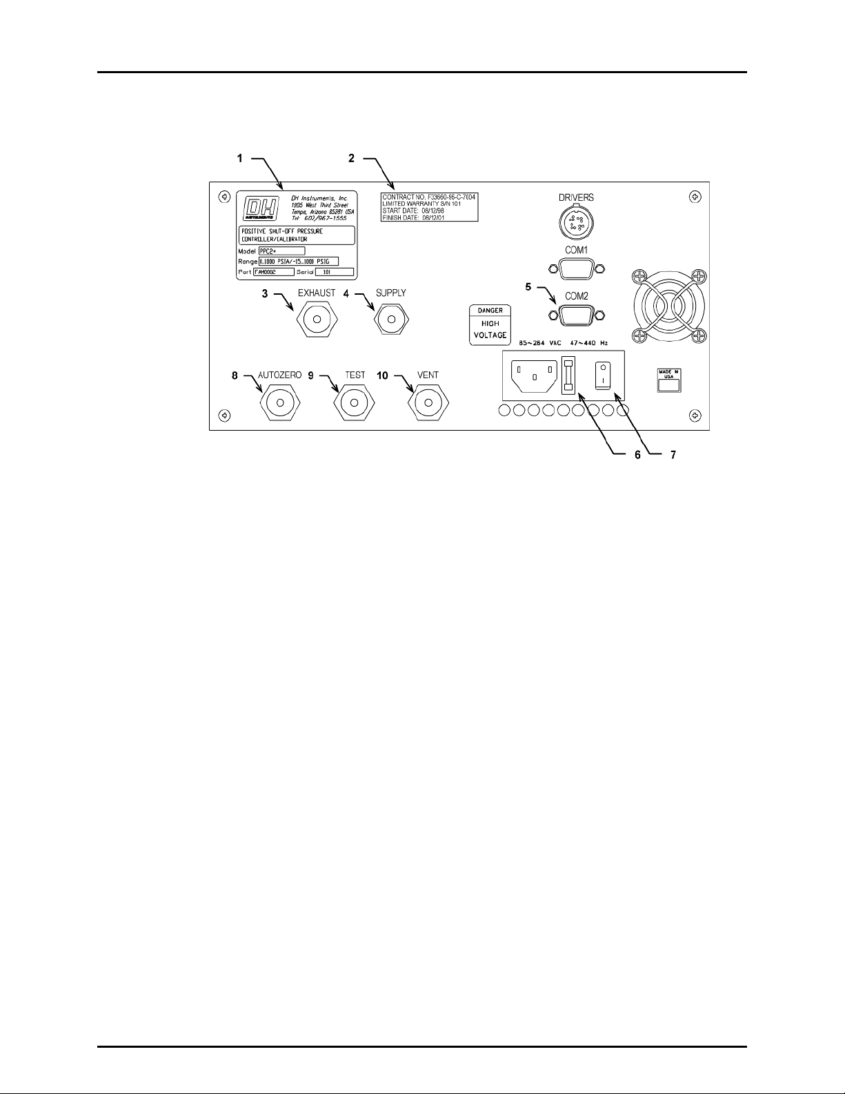
1.2.2 REAR PANEL ASSEMBLY
1. Label, Product
2. Label, Warranty
3. Pressure Connection, EXHAUST
4. Pressure Connection, SUPPLY
5. COM1 Port
6. Fuse
7. Power Switch
8. Fitting, AUTOZERO
9. Fitting, TEST
10. Fitting, VENT
Rear Panel
The rear panel assembly provides pressure connections, the host communications interface
and the power on/off module, and product and warranty labeling. Pressure fittings are
internally secured to prevent loosening when making and breaking connections.
© 1998 DH Instruments, Inc. Page 2
Page 9

1. INTRODUCTION
1.2.3 POWER SUPPLIES
Internal Layout
PPC2 AF has two independent power supplies.
1. + 12 V DC (± 2 %) @ 3.3 Amps: for internal and external valve execution.
2. + 5 V DC (± 2 %) @ 3.0 Amps; + 15 V DC (± 10 % / - 3 %) @ 2.0 Amps; - 15 V DC
(± 5 %) @ 0.35 Amps: for the supply of the micro board and driver board electronics.
1.2.4 MICRO CARD
Internal Layout
The micro card supports a Motorola 68302 microcontroller; EPROM, EEPROM, NVRAM and
flash memories; RS-232 communications; the front panel keypad and display control; and a
two channel frequency counter for reading reference pressure transducers. An I/O port
controls other boards and devices in PPC2 AF.
Page 3 © 1998 DH Instruments, Inc.
Page 10
PPC2 AF OPERATION AND MAINTENANCE MANUAL
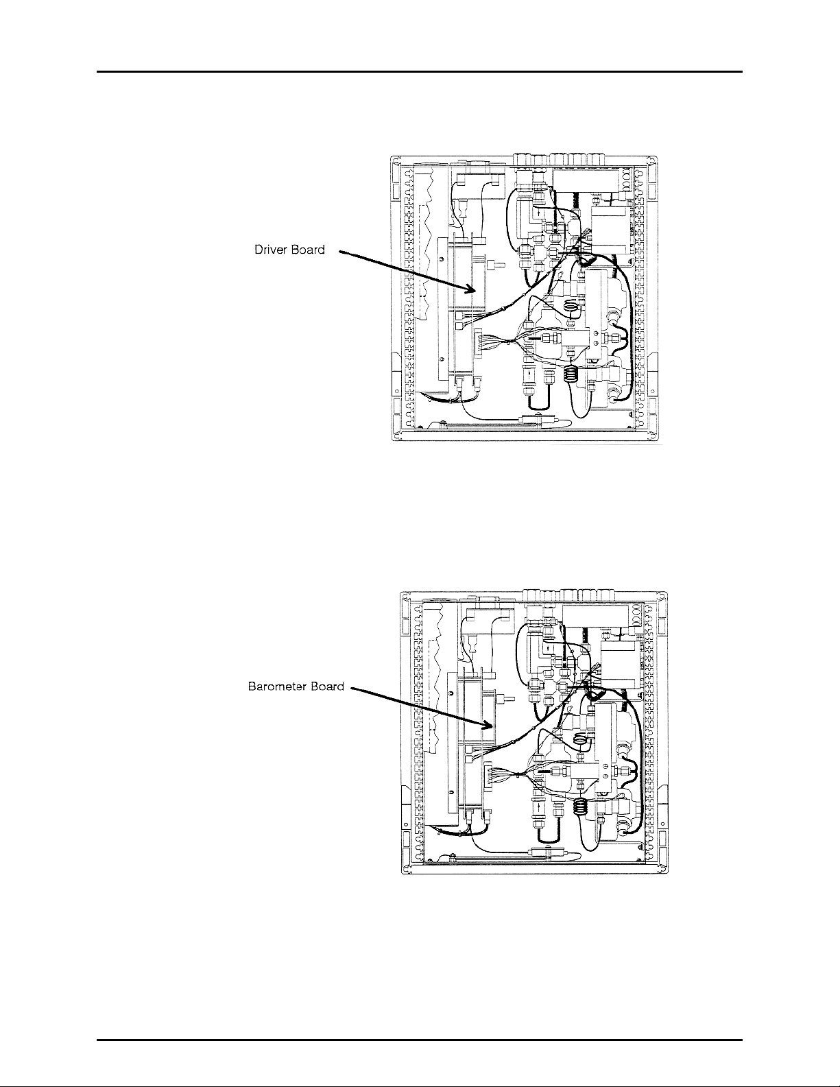
1.2.5 DRIVER BOARD
Internal Layout
The driver board is controlled by the micro card (see Section 1.2.4). It supports the
12 V drivers for the internal and external solenoid valve actuation and the barometer board
(see Section 1.2.6). It also supplies power to the cooling fan.
1.2.6 BAROMETER BOARD
Internal Layout
The barometer board supports a board mounted, barometric range, micromachined silicon
sensor and an ambient temperature sensor. The barometer readings are used for dynamic
atmospheric pressure compensation when measuring gauge pressure with an absolute
reference transducer.
© 1998 DH Instruments, Inc. Page 4
Page 11
1. INTRODUCTION
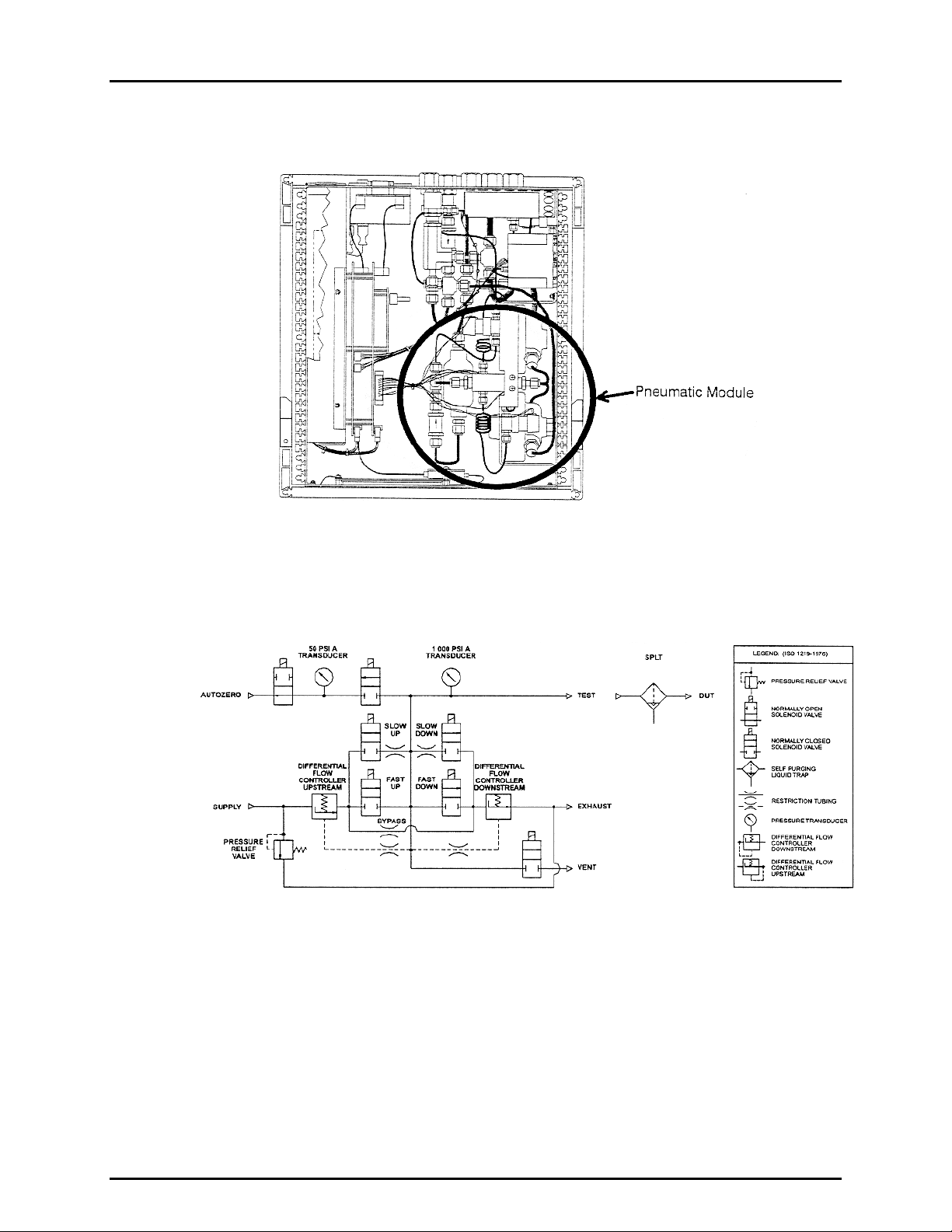
1.2.7 PNEUMATIC MODULE
Internal Layout
The pneumatic module is an integrated assembly that includes two inlet (fast and slow) and
two exhaust control valves and differential pressure regulators. The differential pressure
regulators use pressure feedback to maintain a constant differential pressure across the
control valves. The control valves are solenoid type actuated by 12 V.
Pneumatic Module
Page 5 © 1998 DH Instruments, Inc.
Page 12

PPC2 AF OPERATION AND MAINTENANCE MANUAL
1.2.8 TRANSDUCER SELECTION MODULE
Internal Layout
The transducer selection module includes solenoid valves to connect and disconnect the low
pressure (secondary) reference transducer from the test system and to independently vent
the low pressure reference transducer.
1.2.9 REFERENCE PRESSURE TRANSDUCERS
Internal Layout
There are two reference pressure transducers. Their basic sensing principle is the
measurement of the change in the natural oscillating frequency of a quartz tuning fork with
temperature and with mechanical stress resulting from the change in pressure applied to a
connecting bellows or bourdon tube. Two independent quartz elements are used: one subjected
to pressure related stress; the other is used only to monitor temperature.
© 1998 DH Instruments, Inc. Page 6
Page 13
1. INTRODUCTION
1.2.9.1 HIGH (PRIMARY) PRESSURE REFERENCE TRANSDUCER
The high pressure reference transducer has a full scale range of 1 000 psi
(7 MPa) in gauge and absolute mode.
1.2.9.2 LOW (SECONDARY) PRESSURE REFERENCE TRANSDUCER
The low pressure reference transducer has a full scale range of 35 psi (220 kPa)
in gauge mode and 50 psi (330 kPa) in absolute mode.
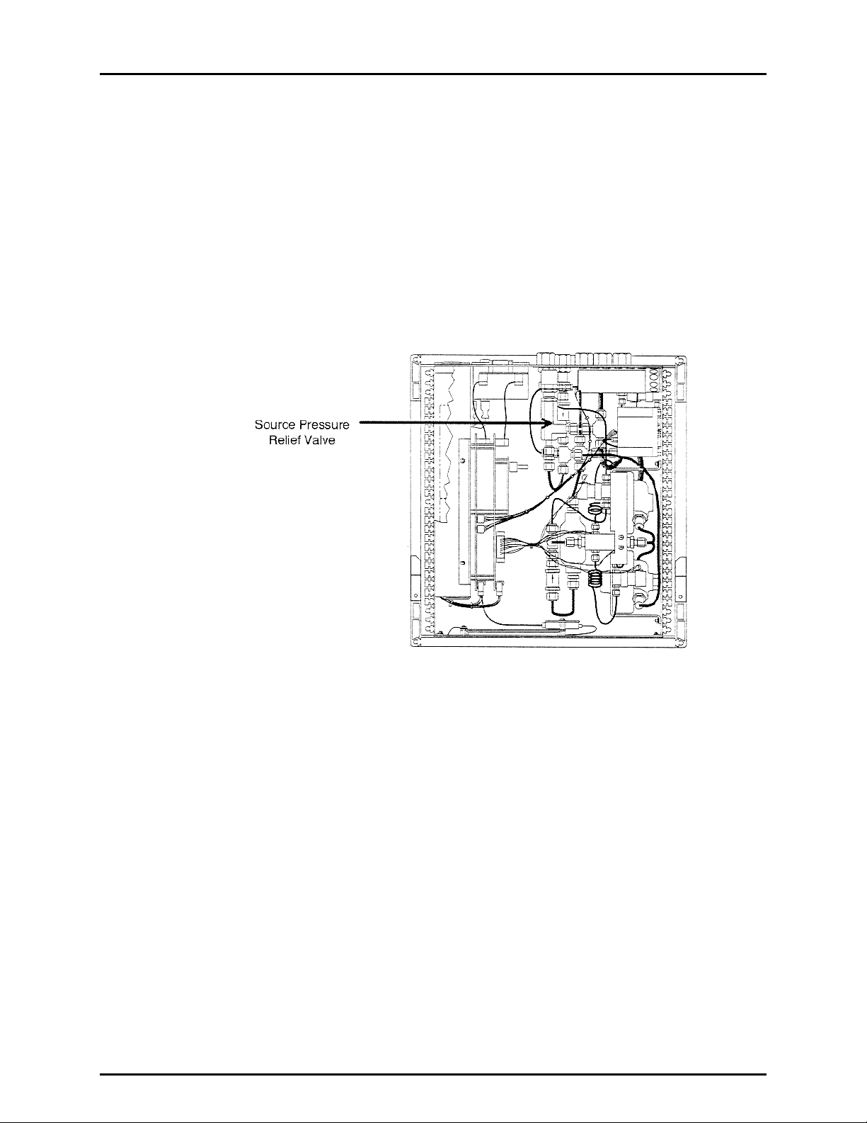
1.2.10 SOURCE PRESSURE RELIEF VALVE
Internal Layout
The source pressure relief valve is a factory set, adjustable, spring loaded pressure relief
valve with a brass body, Viton O-ring seal and stainless steel internal parts. The valve is set
to relieve at 1 200 psi (8.3 MPa).
Page 7 © 1998 DH Instruments, Inc.
Page 14

PPC2 AF OPERATION AND MAINTENANCE MANUAL
1.2.11 SELF PURGING LIQUID TRAP (SPLT)
SPLT (Overall View)
1. Purge Tube
2. Exhaust
Valve
3. Pressure
Connections
4. Electrical
Connection
The SPLT is a free standing accessory designed to protect the PPC2 AF from liquid
contamination returning form the system or device under test. It is made up of a stainless
steel body with an internal X-Type coalescing filter and a bottom drain port fitting with an
electrically actuated purge valve. The filter valve assembly is installed in a mounting stand.
© 1998 DH Instruments, Inc. Page 8
Page 15

1. INTRODUCTION
1.3 SPECIFICATIONS
1.3.1 GENERAL SPECIFICATIONS
Power Requirements
Operating Temperature Range
Storage Temperature Range
Vibration
Weight
Dimensions
Microprocessor
Communication Port
Pressure Ranges
Operating Medium
Pressure Connections
85 to 264 VAC, 47 to 440 Hz, 30 VA max consumption.
15 to 35 °C
- 20 to 70 °C
Meets MIL-T-28800D
12.8 kg (28.2 lb)
7.1" H X 12.6" W X 15.8" D (18 cm X 32 cm X 40 cm)
Motorola 68302, 16 MHz
RS232 (COM1)
-15 to 1 000 psi (7 MPa) gauge/0 to 1 000 psi absolute in six ranges using two
reference pressure transducers and a barometer
Clean, dry, non-corrosive gas
Supply: 1/8 in. NPT F
Test: 1/4 in. NPT F
Vent: 1/4 in. NPT F
Exhaust: 1/4 in. NPT F
AutoZero: 1/4 in. NPT F
1.3.2 PRESSURE MEASUREMENT SPECIFICATIONS
PPC2 AF measures pressures in gauge and absolute mode in six ranges using two reference
pressure transducers and a barometer.
The reference pressure transducers are of the absolute pressure type using an evacuated,
permanently sealed reference. They are used to measure gauge pressures by atmospheric
offset determined by direct measurement when the reference transducer is vented. The
atmospheric offset is dynamically compensated while operating in gauge mode using
measurements of the changes in atmosphere provided by a separate barometer.
1.3.2.1 HIGH PRESSURE REFERENCE TRANSDUCER (HI REF)
Ranges
Measurement Precision
(Combined Linearity, Hysteresis
and Repeatability)
Stability (6 Month with Use of
AutoZero Function)
Resolution
High (3): 0 to 1 000 psi (7 MPa) gauge/absolute
Mid (2): 0 to 600 psi (4 MPa) gauge/absolute
Low (1): 0 to 300 psi (2 MPa) gauge/absolute
± 0.01% F.S. of each range
± 0.005% F.S. of maximum range
1 ppm of maximum range
1.3.2.2 LOW PRESSURE REFERENCE TRANSDUCER (LO REF)
Ranges
Measurement Precision
(Combined Linearity, Hysteresis
and Repeatability)
Stability (6 Month with Use of
AutoZero Function)
Resolution
High (3): - 15 to 35 psi (250 kPa) gauge
0 to 50 psi (350 kPa) absolute
Mid (2): - 15 to 15 psi (100 kPa) gauge
0 to 30 psi (200 kPa) absolute
Low (1): - 15 to 0 psi gauge
0 to 15 psi (100 kPa) absolute
± 0.01 % F.S. of each range
± 0.005 % F.S. of maximum range
1 ppm of maximum range
Page 9 © 1998 DH Instruments, Inc.
Page 16

PPC2 AF OPERATION AND MAINTENANCE MANUAL
1.3.2.3 BAROMETER
The barometric sensor is not used to provide absolute accuracy, it is used only to
measure the changes in atmospheric pressure to provide dynamic compensation
of the reference pressure transducer atmospheric pressure offset measurements
when using a reference pressure transducer to make gauge pressure
measurements.
Range
Accuracy (Nominal)
Resolution
1.3.3 PRESSURE CONTROL SPECIFICATIONS
11 to 16 psia (70 to 110 kPa)
± 0.5 % of reading
0.001 psi (7 Pa)
Control Modes Available
Control Volume
Control Limits
Static and dynamic
0 to 30 in
System defaults provided for each pressure measurement
range but can be customized by the user using the CUSTOM
CONTROL function.
3
(500 cc), ideal 7 to 15 in3 (125 to 250 cc)
1.3.3.1 STATIC PRESSURE CONTROL
Default Hold Limit
Default Stability Limit
± 1 % of F.S. of the active pressure measurement range
± 0.005 % of F.S./sec of the active pressure
measurement range
1.3.3.2 DYNAMIC PRESSURE CONTROL
Default Hold Limit
Default Stability Limit
± 0.05 psi (138 Pa) for Hi Ref ranges (1 to 3)
± 0.0025 psi (7 Pa) for Lo Ref ranges (1 to 3)
± 0.05 psi (350 Pa)/sec for Hi Ref ranges (1 to 3)
± 0.0025 psi (18 Pa)/sec for Lo Ref ranges (1 to 3)
© 1998 DH Instruments, Inc. Page 10
Page 17

2. INSTALLATION AND SHORT TERM STORAGE
22..
I
NNSSTTAALLLLAATTIIOONN AANNDD
I
T
EERRMM
T
S
TTOORRAAGGE
S
E
S
HHOORRTT
S
2.1 UNPACKING AND INSPECTION
2.1.1 REMOVING FROM PACKAGING
PPC2 AF is delivered in a molded medium density polyethylene shipping case with a custom
foam insert for holding the PPC2 AF, SPLT if included, documentation and accessories.
Remove all PPC2 AF elements from the shipping case and remove each element from its
protective plastic bag.
2.1.2 INSPECTING CONTENTS
Check that all items are present and have no visible damage.
PPC2 AF includes:
DESCRIPTION PART NO.
PPC2 AF Pressure Controller/Calibrator 401270
Calibration Certificate 550200
Test Report 550102
ACCESSORIES: 401273
User’s Manual 550090
Power Cord (7.5 ft.) 100770
(4) Rubber Feet Caps 400202
1/4 in. NPT Male X KF 16 SS Vacuum Adaptor 102519
Male Electrical Connector for Drivers 102478
SPLT on Stand (with filter) * 401271
(1) Spare SPLT Filter Element * 102502
Shipping Case with Inserts 401272
* If supplied.
2.2 SITE REQUIREMENTS
The PPC2 AF can be installed on any flat, stable surface at a convenient height. The front feet can be
extended so that the unit can be inclined slightly for easier viewing. The PPC2 AF can also be mounted in
a standard 19" rack mount using the optional rack mount kit.
Minimizing the length of tubing between the PPC2 AF to the device or system to be tested will
enhance control performance and reduce pressure setting times.
Ready access to the PPC2 AF rear panel should be considered to facilitate making and breaking
pressure connections.
The SPLT, if used, needs to be mounted vertically at the low point of the pneumatic system.
Page 11 © 1998 DH Instruments, Inc.
Page 18

PPC2 AF OPERATION AND MAINTENANCE MANUAL
Support facilities required include:
• An electrical power source of 85 to 264 VAC, 47 to 440 Hz.
• A continuous regulated source pressure of 1 100 psi (8 MPa) clean, dry, non-corrosive gas
to connect to the pressure supply. Lower gas pressure sources can be used but should
exceed the maximum desired test output pressure by 10 to 20%.
• A vacuum source of less than 1 psia (7 kPa) and at least 3 cfm (90 lm) is needed to control
under 2 psi (14 kPa) gauge.
When supply pressure is applied to the PPC2 AF supply port, there is a constant gas exhaust through
the EXHAUST port of PPC2 AF to which the vacuum source will be connected. Therefore, the vacuum
source should either be continuously "on" or should bypass to atmosphere when the vacuum source is
"off" to avoid building up pressure on the EXHAUST port and/or the vacuum pump. To conserve gas,
vent the test volume and shut off the pressure supply when PPC2 AF is not in use.
2.3 INITIAL SETUP
2.3.1 PREPARING FOR OPERATION
To prepare PPC2 AF for check out and operation:
• Remove the plastic caps from the five (5) PPC2 AF rear panel pressure connections.
• Remove the protective plastic sheet from the front panel display.
• Install the rubber feet caps onto the bottom case feet, if desired.
2.3.2 POWER CONNECTION
• Check that the PPC2 AF power switch is off.
• Connect the supplied power cable to the rear panel power module.
• Connect the other end of the power cable to an electrical supply of 85 to 264 VAC, 47 to 440 Hz.
2.3.3 CONNECTING TO A PRESSURE SUPPLY (SUPPLY PORT)
Using a pressure connecting hose of appropriate pressure rating, connect the pressure supply
to the SUPPLY connection on the rear panel of PPC2 AF. The PPC2 AF SUPPLY connection
is 1/8 in. NPT female.
Never connect a pressure supply greater than 1 200 psi (8 MPa) to PPC2 AF.
2.3.4 CONNECTING A VACUUM PUMP (EXHAUST PORT)
For PPC2 AF to set pressures under atmosphere and/or to reliably set pressure under 2 psi (914 kPa)
gauge other than zero gauge, a vacuum pump must be connected to the exhaust port.
Never connect a pressure supply to or plug the PPC2 AF EXHAUST port.
When changing the pressure applied to the EXHAUST port from vacuum to atmosphere, be
sure to change the control reference setting (see Section 3.3.1).
© 1998 DH Instruments, Inc. Page 12
Page 19
2. INSTALLATION AND SHORT TERM STORAGE
2.3.5 CONNECTING TO THE DEVICE UNDER TEST (TEST PORT)
See Section 2.3.5.1 before proceeding to connect the device under test.
Using a pressure connecting hose of appropriate pressure rating, connect the device or system to
be tested to the TEST port of the PPC2 AF. The PPC2 AF TEST connection is ¼ in. NPT female.
Minimizing the length of the test connection hose will enhance control performance and
reduce pressure setting time. For normal operation, the total volume of the device of
3
system under test including connecting tubing should be less than 30 in
(500 cc).
PPC2 AF pressure control will not operate properly if there are excessive leaks in the test
system (see Section 3.2.8).
PPC2 AF pressure may be adversely affected if the test connection hose is too restrictive.
For optimum results, the inner diameter of the connecting hose should be > 0.07” (1.75 mm).
NEVER apply pressure to the TEST port without having a pressure supply equal to or great than
the applied pressure connected to the SUPPLY port. When controlling pressure externally, or
measuring external pressure through the SUPPLY port, NEVER
cause the pressure to change at
a very rapid rate. For example, do not vent suddenly by opening an external valve. Internal
PPC2 AF damage may result.
2.3.5.1 INSTALLING THE SPLT
The SPLT (if provided) is intended to collect and exhaust liquid contaminants that may be
present in the device or system under test so that they do not return to the PPC2 AF.
The SPLT is installed in the test connection line at a low point between PPC2 AF and
the device or system under test. The SPLT pressure connections are 1/4 in. NPT female.
Teflon tape or another sealing material should be used to assure leak free
connection of adapters installed in the SPLT pressure connections.
Proper SPLT operation is dependent on the gas flowing through it in the correct
direction. Be sure to connect the SPLT to the device or system under test and
the PPC2 AF following the connector port labels on the SPLT.
Connect the SPLT electrically to the PPC2 AF rear panel DRIVER connection and to the
SPLT terminal blocs. See Appendix 9.2 for information on preparing the SPLT
electrical cable and connection to the SPLT terminal blocs.
The SPLT must be mounted vertically with the purge valve at the bottom to
perform properly. It must be at a lower point in the system than the PPC2 AF
and/or the device under test. In operation, liquid contaminants collected from the
device or system under test will be exhausted through the SPLT purge valve.
Liquid contaminants will be forcibly ejected from the SPLT purge tube. Provision
for collecting the purged liquids should be considered when installing the SPLT.
Excessively dirty or wet filter elements can adversely affect pressure control.
Page 13 © 1998 DH Instruments, Inc.
Page 20

PPC2 AF OPERATION AND MAINTENANCE MANUAL
PPC2 AF with SPLT and DUT
2.3.6 THE VENT CONNECTION (VENT PORT)
The PPC2 AF VENT connection is the system vent to atmosphere point used to set zero
gauge pressure and obtain reference pressure transducer measurements of atmospheric
pressure. Though a pressure hose can be connected to the VENT connection to direct the
vented gas flow, a completely unobstructed connection to atmosphere must be obtained for
PPC2 AF reference pressure measurements to operate normally.
The PPC2 AF VENT connection is 1/4 in. NPT female.
Never plug, obstruct or connect a supply pressure to the PPC2 AF vent connection.
2.3.7 THE AUTOZERO CONNECTION (AUTOZERO PORT)
The PPC2 AF AUTOZERO connection is used for the AutoZero by Vacuum function and is
not needed at start up. It should be left open to atmosphere.
2.4 POWER UP AND VERIFICATION
2.4.1 SWITCH POWER ON
Actuate the power switch on the PPC2 AF rear panel. Observe the front panel display as
PPC2 AF initializes, error checks and goes to the main run screen (see Section 3.1.1).
PPC2 AF operating condition at power up is VENT valve closed, Hi reference pressure
transducer active.
If the PPC2 AF fails to reach the main run screen, service is required. Record the sequences
of operation and displays observed.
If the active range on power down was a Hi reference transducer range, the same range will
be active on the next power up. If the active power down range was a Lo reference
transducer range, range H3 will be active on power up. This is to protect the Lo reference
transducer from accidental overpressure (see Section 3.1.2.5).
© 1998 DH Instruments, Inc. Page 14
Page 21

2. INSTALLATION AND SHORT TERM STORAGE
2.4.2 SET THE USER LEVEL (INITIAL START UP ONLY)
PPC2 AF's front panel interface provides the means to access all PPC2 AF data and
functions including functions which, if used inadvertently or incorrectly, could change critical
metrological and/or operational parameters. The USER LEVEL function (see Section 3.4.4.6)
allows these areas to be password protected. The "low" security level protects only the most
critical internal calibration data. It is recommended that this level be set on all PPC2 AF's
even if no special security precautions are desired.
2.4.3 CHECK PROPER PRESSURE MEASUREMENT OPERATION
2.4.3.1 CHECKING ABSOLUTE PRESSURE MEASUREMENT
If the PPC2 AF is not vented, press the VENT direct pressure control key to vent
it (see Section 3.1.2.2).
Press the UNIT function key (see Section 3.2.2). Select psi and then select
absolute mode.
Using the RANGE function key to change ranges (see Section 3.2.1), observe the
current value of atmospheric pressure displayed by each range. Check that
these values agree within ± 0.2 psi (1.4 kPa). If they do not agree, PPC2 AF may
need calibration or repair.
2.4.3.2 CHECKING GAUGE PRESSURE MEASUREMENT
If the PPC2 AF is not vented, press the VENT direct pressure control key to vent
it (see Section 3.1.2.2).
Press the UNIT function key. Select psi and then select gauge mode.
Using the RANGE function key to change ranges, observe that zero psi, ± 0.01 psi
is indicated for each range within 10 seconds. If it is not, PPC2 AF may need repair.
2.4.4 LEAK CHECK
If desired, perform a leak check of the test system (see Section 3.2.8).
2.4.5 PURGE
If the SPLT is included and installed in the test line, perform a purge of the system if it may be
liquid contaminated and descending pressures will be controlled (see Section 3.2.8).
Operating the PPC2 AF connected to a system with liquid contaminants without taking
proper precautions to purge the system and test line may cause contamination of the
PPC2 AF that will require non-warranty service.
Page 15 © 1998 DH Instruments, Inc.
Page 22

PPC2 AF OPERATION AND MAINTENANCE MANUAL
2.4.6 CHECK PROPER PRESSURE CONTROL OPERATION
Select a pressure range using the RANGE function (see Section 3.2.1).
Press the CONTROL function key and select "dynamic" (see Section 3.2.3).
Select1Vac under 1ControlRef of the SETUP menu if a vacuum supply is connected to the
PPC2 AF EXHAUST port, otherwise, set 2Atm (see Sections 3.3.1).
Press ENTER, specify a target pressure within the current range to be set and press ENTER
again (see Section 3.2.3).
PPC2 AF should set the target pressure and indicate "ready" (see Section 3.1.2.4)
continuously in 30 to 60 seconds. If it does not, see Section 6.
2.5 SHORT TERM STORAGE
The following is recommended for short term storage of PPC2 AF:
• Vent the PPC2 AF test pressure.
• Turn the power "off" using the rear panel power switch.
• Shut-off or disconnect the pressure supply.
• Shut-off or disconnect the vacuum supply.
© 1998 DH Instruments, Inc. Page 16
Page 23

3. OPERATION
33..
O
PPEERRAATTIIOON
O
N
3.1 GENERAL/MANUAL OPERATION
PPC2 AF is designed to offer a balance between simple, straight forward operation and the
availability of a wide variety of functions with a high level of operator discretion if desired. The local
operator interface is through a 2 X 20 display, a 4 X 4 keypad and 4 direct pressure control keys.
3.1.1 THE MAIN RUN SCREEN
The PPC2 AF main run screen is its home display that is reached on power up and from
which other functions and menus are accessed. It is the very top level of all menu structures.
The main run screen is where the operator works with PPC2 AF to set and read pressures.
It provides complete information on the system's current configuration and operating status.
1. * Ready/Not Ready indication (See Section 3.1.2.4).
* when Ready,
if Not Ready.
2. PRESSURE1: Numerical value and sign of pressure
currently measured by currently active transducer and range.
3. UNIT: Current unit of measure of pressure indication
(see Section 3.2.2).
4. M: Pressure measurement mode: g for gauge, a for
absolute (see Section 3.2.2).
5. H: Indicates if a head correction is applied. H if applied,
blank if not (see Section 3.2.7).
6. SR: Indicates active reference transducer (H for high, L for low) and range (1 = low, 2 = mid, 3 = hi)
(see Section 3.2.1).
7. T: Indicates whether number following is target pressure (T), rate of change of pressure (R) or deviation
from target value (D) (see Section 3.2.3).
• Target pressure (T) will be indicated when:
- Dynamic control is active and pressure is NOT READY.
- Static control is active and valves are operating.
• Deviation (D) will be indicated when:
- Dynamic control is active and pressure is READY.
• Rate of change (R) will be indicated when:
- No control is active, i.e. control is suspended or
system is vented.
- Static control is active, and no valves are active.
8. PRESSURE2: Numerical sign and value of either target pressure, rate of change of pressure or deviation
from target. Target value and deviation in the same pressure unit as the current unit in 3. above. Rate of
change of pressure is in current unit per second (see Section 3.2.3).
9. CC: Pressure control mode (S for static, D for dynamic) with a (C) appended if custom control settings are
in use. These characters flash when the system is controlling. In static mode, if control is active they flash
even if no valve is operating, for example while inside the hold limit and waiting for stability. Characters flash
while controlling pressure down to vent but not when vent valve is open (see Sections 3.2.3 and 3.2.6).
10. NN/NN: Used only when running a sequence. Indicates number of increment currently being worked on
over total number of increments in the sequence or enter when “ready”. Changes to a countdown time during
count down when next increment of sequence is on timed delay rather than enter.
or indication direction of pressure evolution
*PRESSURE1 UNITMH SR
TPRESSURE2 CC NN/NN
PPC2 AF has a screen saver function which causes the display to dim if no key is pressed
for 10 minutes. Pressing a key restores full power to the display.
Page 17 © 1998 DH Instruments, Inc.
Page 24

PPC2 AF OPERATION AND MAINTENANCE MANUAL
3.1.2 GENERAL OPERATING PRINCIPLES
3.1.2.1 MAIN KEYPAD LAYOUT AND PROTOCOL
The PPC2 AF has a 4 X 4 keypad for local operator access to direct functions,
function menus and for data entry.
3. The Editing and Execution keys are for causing execution, suspending execution, backing up
in menus and editing entries.
1. The Function/Data keys allow very
commonly used functions to be
accessed directly by a single
keystroke when pressed from the
main run screen. The name of the
function is on the bottom half of the
key (see Section 3.2). These keys
enter numerical values when editing.
2. The Menu/Data keys provide access
to function menus when pressed
from the main run screen. The menu
name is on the bottom half of the
key. The SETUP menu is for more
frequently used functions (see
Section 3.3). The SPECIAL menu is
for functions that are not generally
used as a part of normal operation
(see Section 3.4). These keys enter
numerical values when editing.
Keypad
The ENTER key generally causes execution or forward movement in the menu tree.
ENTER from the main run screen allows an automated pressure control
command to be given.
The ESCAPE key moves back in the menu tree and/or causes execution to
cease or suspend. Pressing ESCAPE repeatedly always eventually brings you
back to the main run screen and from there will allow a momentary viewing of the
PPC2 AF introduction screen.
The
key changes a numerical sign when editing. It also toggles through
multiple screens when available.
The
and keys allow reverse and forward cursor movement when editing
data entry.
Some screens go beyond the two lines provided by the display. This is
indicated by a flashing arrow in the second line of the display. Use the ←
→ arrow keys to move the cursor to access the lines that are not
and
visible or directly enter the number of the desired menu choice if you know it.
3.1.2.2 DIRECT PRESSURE CONTROL KEYS
Direct Pressure Control Keys
The direct pressure control keys provide direct manual control of pressure
increase, decrease and vent. They can be useful in adjusting pressure when
automated pressure control to a target value is not needed.
© 1998 DH Instruments, Inc. Page 18
Page 25

3. OPERATION
The direct pressure control keys interrupt and override automated pressure control.
The VENT key causes the system to control pressure to near atmospheric
pressure and then open the system vent valve (see Section 1.2.7). Vent valve
open is indicated by lighting a red LED just above the VENT key. The vent valve
will remain open until the VENT key is pressed again or pressure is changed by a
direct pressure control key or an automated pressure control command. The VENT
key also causes the purge function to execute when the PPC2 AF LEAK
CHECK/PURGE function is active (see Section 3.2.8).
and keys cause pressure to increase or decrease at the slow slew rate.
The
Pressing the FAST key while pressing an
increase or decrease speed to change from slow to fast.
or key will cause the pressure
3.1.2.3 AUTOMATED PRESSURE CONTROL
PPC2 AF automated pressure control provides automated adjustment and control
of pressure to a user designated target value. This feature allows pressure
values to be set simply and precisely by simple numerical entry. Pressing
ENTER from the main run screen allows a pressure control target value to be
entered and executed. Pressing ESCAPE or a direct pressure control key will
cause pressure control to be interrupted.
PPC2 AF supports two pressure control modes, static and dynamic, to meet
different pressure setting and controlling requirements. Pressure control
parameters for each control mode are automatically adjusted to optimal values
for each PPC2 AF range when the control mode is selected in that range (see
Section 3.2.3). If desired, control parameters can be customized by the user
using the CUSTOM CONTROL function (see Section 3.2.6).
Control parameters:
Target Value: The pressure setpoint specified by the operator.
Hold Limit: A symmetrical positive and negative limit around the target value.
Stability Limit: A rate of change of pressure limit in units of pressure/second.
See Sections 3.1.2.3.1 and 3.1.2.3.2 for a detailed explanation of each control mode
and its advantages, the default control parameters and the Custom Control options.
3.1.2.3.1 Static Control
Static control mode is designed to set the pressure near the target value and then
stop controlling to allow pressure to stabilize naturally. The advantage of this
control mode is that pressure can be measured without interference from a
pressure control system. In a system without excessive leaks, the pressure
stability achieved, especially at low pressures, may be greater than the stability
with which the pressure control system can actively control pressure. Using static
control to control pressures near the desired set point and then measuring back
the stabilized pressure without interference of the control function, can allow
control errors to be eliminated. However, the final pressure achieved will be
different from the target value.
Page 19 © 1998 DH Instruments, Inc.
Page 26

PPC2 AF OPERATION AND MAINTENANCE MANUAL
During static pressure control, the hold limit is active. If the pressure goes
outside of the hold limit, a "not ready" condition will occur (see Section 3.1.2.4)
and pressure will be readjusted to the target value (see Section 3.2.3 for default hold
and stability limit values and Section 3.2.6 for setting the hold and stability limits).
Static Pressure Control Operation
3.1.2.3.2 Dynamic Control
Dynamic control mode is designed to set the pressure to the target value and
control continuously to keep pressure within the hold limit and as close to the
target value as possible. The advantage of this control mode is that the final
pressure achieved will be the same as the target value. However, unlike static
control, in dynamic control, a control error will be included in the pressure
achieved. The maximum value of the control error is equal to the hold limit. The
average value of the control error is generally well inside the hold limit.
During dynamic pressure control, the hold limit is active. If the pressure goes outside
of the hold limit, a "not ready" condition will occur (see Section 3.1.3.4; see
Section 3.2.3 for default hold limit values and Section 3.2.6 for setting the hold limit).
Dynamic Pressure Control Operation
© 1998 DH Instruments, Inc. Page 20
Page 27

3. OPERATION
3.1.2.4 PRESSURE READY/NOT READY INDICATION
The far left character of the display provides a pressure "Ready/Not Ready" indication.
This indication is intended to provide the user with a clear and objective criterion
for determining when a valid pressure measurement can be made.
Ready/Not Ready indications are:
* : Pressure "ready".
: Pressure "not ready" and decreasing.
: Pressure "not ready" and increasing.
When pressure control is not active, a "ready" condition will occur any time no
control valve is operating and the pressure rate of change is inside the stability
limit. The stability limit is defined in terms of rate of change of pressure in current
pressure units per second.
The determination of the "ready/not ready" condition is different for static and
dynamic pressure control. Pressure Ready/Not Ready parameters are set by
default when a control mode is selected and can be customized (see Sections
3.2.3 and 3.2.6).
3.1.2.4.1 Static Control Ready/Not Ready
When static pressure control mode is active a "ready" condition will occur when:
1. No control valve is operating.
2. The current measured pressure is inside the hold limit.
3. The rate of change of pressure is less than the current stability limit.
Ready/Not Ready Static Control Mode
Page 21 © 1998 DH Instruments, Inc.
Page 28

PPC2 AF OPERATION AND MAINTENANCE MANUAL
3.1.2.4.2 Dynamic Control Ready/Not Ready
When dynamic pressure control mode is active a "ready" condition will occur when:
1. The current measured pressure is inside the hold limit.
Ready/Not Ready in Dynamic Pressure Control Mode
3.1.2.4.3 Ready/Not Ready When Automated Pressure Control is Not Active
When no automated pressure control is active, "ready" is indicated whenever the
rate of change of pressure is less than the current stability limit.
3.1.2.5 MULTIPLE PRESSURE RANGES
PPC2 AF has two reference pressure transducers each of which has three
ranges for a total of six pressure ranges. This multiranging feature allows
accuracy to be optimized for the range of pressure in which you are working.
Generally, the best range to select (see Section 3.2.1) is that whose full scale is
closest to, but not less than, the maximum pressure at which you need to work.
PPC2 AF handles all of the data and internal valving operations needed to make
range changes occur transparently to the operator when the RANGE function is
used to select a range. Ranges available can be viewed at any time but changing
ranges can only occur when PPC2 AF is vented.
When ranges are changed, the upper limit is automatically changed to the default
for that range or to the last upper limit that was set for that range (see Section 3.2.4).
In addition, most other functions are range specific (see Section 3.2.1 below).
PPC2 AF has six ranges on two transducers. In general, user settings and
operational adjustments are specific to the range currently in use, as if you
had six instruments rather than one.
The PPC2 AF internal valving for handling of the two reference transducers is:
Valving – Hi and Lo Reference Transducers
© 1998 DH Instruments, Inc. Page 22
Page 29

3. OPERATION
RANGES AND IDENTIFICATION
The currently active reference transducer and range is continuously displayed in
the upper right hand corner of the main run screen. Ranges available and main
run screen indication are as follows:
REFERENCE TRANSDUCER
AND RANGE NUMBER
Lo, 1 (Lo) 0/15 L1
Lo, 2 (Mid) 15/30 L2
Lo, 3 (Hi) 35/50 L3
Hi, 1 (Lo) 300/300 H1
Hi, 2 (Mid) 600/600 H2
Hi, 3 (Hi) 1 000/1 000 H3
RANGE (PSI)
GAUGE/ABSOLUTE
MAIN RUN SCREEN
INDICATION
All ranges start at zero in absolute mode and in gauge mode go negative by the
current value of atmospheric pressure.
3.2 DIRECT FUNCTION KEYS
3.2.1 RANGE
PURPOSE
To change the currently active pressure measurement range.
PRINCIPLE
PPC2 AF uses a 1 000 psi (7 MPa) absolute transducer and a 50 psi (350 kPa) absolute
transducer to measure reference pressures. In addition, each one of these transducers is
triple ranged providing a total of six pressure ranges over the 1 000 psi pressure range of the
PPC2 AF (see Section 3.1.2.5).
The RANGE function keys allows ranges to be selected including automated switching of
transducers when necessary with built-in logic to prevent accidental overpressure of the low
pressure transducer.
PPC2 AF functions and settings such as pressure unit of measure (UNIT) and control mode
(CONTROL) are range specific. Only the HEAD function is not range specific (see Section 3.4.2).
Changes made while in one range apply to that range only and will not affect the other ranges.
OPERATION
Pressing the RANGE function key activates the range viewing and selecting function.
Pressing the +/- key or the RANGE key again while in the RANGE functions steps through
displays of available ranges, Lo to Hi. Pressing ENTER while in the RANGE function when
PPC2 AF is vented makes the currently displayed range the active range. Pressing ESCAPE
while in the range function returns to the main run screen with no range change having been made.
Page 23 © 1998 DH Instruments, Inc.
Page 30

PPC2 AF OPERATION AND MAINTENANCE MANUAL
When the RANGE function key is first pressed, the current reference transducer and range
being used are displayed, for example:
1. Identifies reference transducer in use (Lo or Hi).
2. Identifies range of that reference transducer currently in use
(1, 2 or 3, Lo to Hi).
3. Abbreviated range designation.
4. Units of measure and pressure range for that transducer and
range number when used in gauge (g) or absolute(a) mode.
Pressing the
key or pressing the RANGE key again causes the screen to step through
the other available ranges in sequence Lo to Hi, for example:
Current LO, Rng3 L3
psi 35 g/50 a
1. Identifies reference transducer (Lo or Hi).
2. Identifies range of number on that reference transducer (1, 2 or 3).
3. Abbreviated range designation.
4. Units of measure and pressure range for that transducer and
that range when used in gauge (g) or absolute(a) mode.
Select HI, Rng1 H1
psi 300 g/300 a
Range limits are given in the pressure unit that is currently active for that range.
To protect against overpressure of the Lo pressure reference transducer and avoid
accidentally exceeding range upper limits, the active range can only be changed when the
system is vented. If ENTER is pressed while in the RANGE function when PPC2 AF is not
vented, the display will indicate "Vent system fully to change range". Press ESCAPE or ENTER
to reach the main run screen and vent using the VENT direct pressure control key. Once
the system has fully vented, use the RANGE function to make the desired range change.
RANGE SPECIFIC FUNCTIONS AND SETTINGS
In general, PPC2 AF functions and settings are channel specific. They are set and stored for
each range so that changing them when in one range does not change them in the other
ranges and when you return to a range, you will find the settings you left.
The only functions and settings that are not range specific are:
Functions: HEAD, ANALOG
Setup Menu: 1ControlRef, 4Drivers
3.2.2 UNIT
PURPOSE
To specify the pressure unit in which PPC2 AF displays pressure values.
See also Section 3.4.1.
© 1998 DH Instruments, Inc. Page 24
Page 31

3. OPERATION
OPERATION
To change the pressure unit of measure, press the
UNIT function key. The display is:
1psi 2kPa 3inHg
4inWa 5mmHg 6ft
Select the desired pressure unit. ENTER selects the unit and goes to measurement mode
selection: 1gauge or 2absolute. Making the selection returns to the main run screen with the
selected measurement unit and mode active.
If the pressure unit selected is inWa the reference
temperature for water density must be specified.
When inWa is selected as the unit, the next display is:
Select the desired reference temperature for water density using the
Select inWa ref temp
4ºC 20ºC 60ºF
← or → key to move
the cursor. ENTER returns to the main run screen with the inWa based on water density at
the selected reference temperature as the pressure unit. The current inWa reference
temperature can be viewed by observing the position of the cursor in the reference
temperature screen.
No reference temperature selection is necessary for the unit mmWa as the only reference
temperature commonly used for mmWa is 4º C.
See Section 9.3 for tables of the conversion factors used by PPC2 AF.
The choice of six units available under the UNIT function can be modified from a wider
selection by the user. See Section 3.4.1.
3.2.3 CONTROL
PURPOSE
To set the automated pressure control mode for the currently active range with default control
parameters.
PRINCIPLE
The CONTROL function allows the active control mode for the current range to be set to
either static control or dynamic control (see Section 3.1.2.3). The control mode set is specific
to the current range and will be maintained with that range when ranges are changed.
When the control mode is set using the CONTROL function, CONTROL parameters are set
to system default parameters which have been determined to be those most suitable for the
typical user to operate within PPC2 AF pressure control and measurement specifications
(see SYSTEM DEFAULT CONTROL PARAMETERS below). If desired, control mode
parameters can be customized by the user using the CUSTOM CONTROL function
(see Section 3.2.6).
For a complete description of the operation and purpose of static and dynamic control modes,
see Section 3.1.2.3.
Page 25 © 1998 DH Instruments, Inc.
Page 32

PPC2 AF OPERATION AND MAINTENANCE MANUAL
OPERATION
To select the control mode for the currently active
range and set control parameters to the default control
parameters, press the CONTROL function key from
the main run screen. The display is:
Control mode:
1dynamic 2static
Selecting 1static or 2dynamic causes the selected pressure control mode to be activated with
default control parameters and returns to the main run screen.
Control mode setting is range specific. A change in control mode made while in one
PPC2 AF range does not affect the control mode setting in other ranges (see
Section 3.2.1).
The current control mode is indicated by two characters in the middle of the bottom line
of the main run screen (S for static and D for dynamic with C appended if custom control
settings are in use). (See Section 3.1.1.)
In dynamic control mode, whenever the pressure is "ready" (inside the hold limit), the
display of measured pressure is equal to the target pressure. This is because in dynamic
control mode, when the pressure is "ready", it is assumed that the measured pressure
equals the target pressure. This is not true when setting zero in absolute measure mode
(see Section 3.2.3.1.2).
SYSTEM DEFAULT CONTROL PARAMETERS
LO REFERENCE TRANSDUCER
RANGE 1, 2, 3
HOLD LIMIT STABILITY LIMIT HOLD LIMIT STABILITY LIMIT
Static
Mode
Dynamic
Mode
± 1% of F.S. of the
active pressure
measurement range
± 0.0025 psi
(35 Pa )
± 0.005% of F.S./sec
of the active pressure
measurement range.
± 0.0025 psi
(35 Pa)/sec
HI REFERENCE TRANSDUCER
RANGE 1, 2, 3
± 1% of F.S. of the
active pressure
measurement range
± 0.05 psi (350 Pa ) ± 0.05 psi
± 0.005% of F.S./sec
of the active pressure
measurement range.
(350 Pa )/sec
3.2.3.1 EXECUTING AUTOMATED PRESSURE CONTROL COMMANDS
PURPOSE
To use the automated pressure control functions of PPC2 AF to set target
pressure values.
© 1998 DH Instruments, Inc. Page 26
Page 33

3. OPERATION
OPERATION
To set a pressure press ENTER from the main run screen. The display is:
1. Ready/Not Ready indication, current pressure,
units, measurement mode, range (regular first
line of main run screen).
2. Entry field for target pressure to be set
automatically. Comes up with last entry or
zero if pressure measurement units have
been changed, range has been changed, or
system has been vented.
* 134.56 psi a H3
Target: 135.000 psi
Use the numerical keys and editing keys to enter the target pressure value
desired (see Section 3.2.3.1.2 for information on zero pressure commands).
Press ENTER to start pressure control to the target pressure and return to the
main run screen. The main run screen is:
1. "Ready/Not Ready indication, current
pressure, units, measurement mode, range
(regular first line of main run screen).
2. Target pressure value (T) or pressure rate of
change value (R) if in dynamic control and
pressure is in ready condition.
3. Current control mode flashing to indicate that
control is on.
134.56 psi a H3
T 250.000 DC
A target pressure entry that exceeds the current upper limit (see Section
3.2.4 or that is out of range will not be accepted as the target value when
ENTER is pressed.
Observe the Ready/Not Ready indication for indication of when ready conditions
have been satisfied (see Section 3.1.2.4). PPC2 AF will continue controlling
following static or dynamic control operation protocol (see Section 3.1.2.3) until
automated pressure control is interrupted.
See Section 6 if PPC2 AF is unable to control pressure or appears to control
pressure poorly.
For PPC2 AF to set pressures under atmosphere and/or to reliably set
pressures under 2 psi (14 kPa) gauge other than zero gauge, a vacuum pump
must be connected to the EXHAUST port (see Section 2.3.4) and PPC2 AF
must be set up for control using a vacuum reference (see Section 3.3.1).
Zero gauge pressure can always be set.
3.2.3.1.1 Interrupting Automated Pressure Control
Automated pressure control is interrupted by:
• Pressing ESCAPE.
• Pressing any direct pressure control key (see Section 3.1.2.2).
• Pressing any function key.
To start automated pressure control again, press ENTER and ENTER a target
pressure value.
Page 27 © 1998 DH Instruments, Inc.
Page 34

PPC2 AF OPERATION AND MAINTENANCE MANUAL
3.2.3.1.2 Automated Pressure Commands for Zero Pressure
Zero in gauge mode:
Zero in absolute mode:
A command for automated pressure control of zero when in gauge
pressure measurement mode is interpreted in the same manner as if
the VENT direct pressure control key had been pressed (see Section
3.1.2.2). A "ready" condition will occur when the vent valve has been
opened and the pressure meets the current stability test.
Even with a vacuum pump connected to its reference EXHAUST,
PPC2 AF cannot set absolute zero pressure due to internal
restrictions and the continuous gas flow through its EXHAUST port.
When a command for automated pressure control of zero when in
absolute pressure measurement mode is given, PPC2 AF responds
by reducing the pressure as far as possible using down fast pressure
control. A "ready" condition will be indicated when the stability limit is
reached with the control down fast remaining open.
Due to the manner in which PPC2 AF handles an automated pressure
command for zero in absolute pressure measurement mode, a ready
condition can occur at a pressure well outside of the hold limit. When setting
zero in absolute measurement mode, the "ready" condition should not be
used as an indication that the pressure is zero. "Ready" is an indication that
the PPC2 AF has reduced the pressure as far as possible and that the
pressure is now stable. The current displayed pressure should be used as
the value of pressure applied to the device or system under test.
3.2.4 UPPER LIMIT
PURPOSE
To set the upper limit pressure value for a pressure range.
PRINCIPLE
The UPPER LIMIT function provides the capability to enter a maximum pressure not to be
exceeded when using a specific range. Automated pressure control target values above the
upper limit will not be accepted and direct pressure control keys will shut off when the upper
limit is reached.
The UPPER LIMIT function is most often used to protect the device or system that the
PPC2 AF is testing from accidental overpressure.
If no upper limit value is entered by the user, the upper limit for each range is set by
default to 105 % of the active range for ranges L3 and H3 and to 115 % of the active range
for all other ranges.
OPERATION
When the UPPER LIMIT function key is pressed from the main run screen the display is:
RngH3 upper limit
1. Entry field to enter desired upper limit value.
1050 psi a
Enter the desired upper limit value and PPC2 AF returns to main run screen with new upper
limit value active.
© 1998 DH Instruments, Inc. Page 28
Page 35

3. OPERATION
Upper limit values are always specified in absolute pressure. Keep this in mind when
setting upper limits for gauge measurement mode.
Upper limits are always specified in the current pressure unit. This creates an anomaly, in
the case of altitude units, since the maximum pressure defined in MIL-STD 859A is
roughly 179 kPaa (26 psia). This corresponds to an altitude of – 5 000m (- 16 480ft).
Therefore, it is not possible to specify an upper limit in altitude that corresponds to a
pressure greater than 179 kPaa (26 psia).
When the UPPER LIMIT has been exceeded, the display of current pressure flashes.
Reduce pressure using direct pressure control keys or an automated pressure command to
return to normal operation.
3.2.5 SEQ
PURPOSE
To execute a programmed sequence of automated pressure control target values
PRINCIPLE
The sequence function is intended to facilitate the execution of a series of pressure control
target values such as is commonly needed when PPC2 AF is used to run a typical calibration
sequence on a device or system being tested.
There are two types of sequences. Quick Sequence (see Section 3.2.5.1) allows quick
definition and execution of a sequence in the current range and using all of the current
settings (i.e. pressure units, control mode, control settings). File Sequence (see Section
3.2.5.3) allows execution of a preprogrammed sequence script including the PPC2 AF range
to use, measurement mode, control mode, target values and other operational settings (see
Section 3.3.3).
OPERATION
When the SEQ function key is pressed from the main
run screen, the display is :
Run sequence
1Quick 2File
Select the sequence type desired (see Sections 3.2.5.1 or 3.2.5.2).
3.2.5.1 SETTING UP/EDITING A QUICK SEQUENCE
OPERATION
When 1Quick is selected from the SEQ
function menu, the display is:
This selection provides the choice between running the quick sequence that is
currently set up or changing the quick sequence set up. 1Yes will cause the
currently defined quick sequence to run (see Section 3.2.5.3). 2No will go to the
quick sequence set up/edit routine.
Run current quick
sequence 1Yes 2No
Page 29 © 1998 DH Instruments, Inc.
Page 36

PPC2 AF OPERATION AND MAINTENANCE MANUAL
When 2No is selected from the Run Current Quick Sequence menu, the setup/edit routine is accessed. The first display is:
1. Entry field for sequence full scale value.
Recalls last entered value.
Enter sequence FS
100 psi a
This entry determines the maximum pressure (furthest from zero) of the quick
pressure sequence. Enter the desired sequence maximum pressure and press
ENTER.
Sequence FS must be less than the pressure upper limit of the currently
active pressure range (see Section 3.2.4).
The next display is:
Enter sequence FS
1. Entry field for sequence pressure increment in
% of full scale. Recalls last entered value.
increment 20 % FS
This selection determines the size of the pressure increment in terms of % of the
full scale (FS) value entered in the previous screen. The sequence will be
between zero and full scale in pressure steps of (full scale x increment %) starting
from zero and ending with the uneven increment if applicable. Enter the desired
pressure increment and press ENTER.
The next display is:
Increment order?
1Up 2Down 3Both
This selection determines the order in which the sequence increments will
execute. 1Up will cause the sequence to execute between zero and the full scale
value. 2Down will cause the sequence to execute between the full scale value
and zero. 3Both will cause the sequence to execute from zero to full scale and
back to zero.
After making the increment order
selection the next display is:
This selection determines when, during running of the sequence, the pressure
target value will change to the next value in the sequence. If 1ENTER is
selected, the sequence will proceed to the next target value when ENTER is
pressed. If 2Timer is selected, a timer will be started when a pressure ready
condition is reached (see Section 3.1.2.4) and the sequence will continue to the
next pressure control target value without operator intervention once the timer
has expired. After selecting 2Timer, an additional screen is presented for entry of
the timer value in seconds (minimum 1, maximum 999).
After making the next increment on
selection the next display is:
Select 1Yes to run the quick sequence that has just been set up/edited (see
Running a Quick Sequence below). Select 2No to setup/edit the current
sequence. Press ESCAPE to back out of the SEQ function if desired.
© 1998 DH Instruments, Inc. Page 30
Next increment on?
1Enter 2Timer
Run current quick
sequence 1Yes 2No
Page 37

3. OPERATION
3.2.5.2 SETTING UP/EDITING A FILE SEQUENCE
See Section 3.3.3.
3.2.5.3 RUNNING A SEQUENCE
OPERATION
Selecting 1Yes in the Run current quick sequence menu causes the current quick
sequence to execute.
Entering a valid sequence file number from the Run Sequence File # causes a file
sequence to execute.
A Quick Sequence executes in the current range with the current settings. A File
Sequence sets up the range and other settings as specified in the sequence file
(see Sections 3.2.5 and 3.3.3.)
When initializing execution of a quick sequence, PPC2 AF checks: a) if the
sequence full scale pressure exceeds the current upper limit; b) if PPC2 AF is
in absolute measure mode, that the sequence does not contain negative
values. If either of these conditions exists, an error message will be
displayed and the sequence will not be run.
To run a file sequence that specifies a reference pressure transducer range
other than the current range, PPC2 AF must be vented because the range
cannot be changed when PPC2 AF is not vented.
To run a file sequence, the sequence file number selected must already have
been setup using 3Sequence under the SETUP menu (see Section 3.3.3)
The first display is:
Enter runs sequence
1. Maximum pressure of the sequence that is
about to run.
100 psi a FS
This screen is offered as a means for the user to check, prior to execution, that
the correct sequence is selected and that it does not exceed the range of the device or
system being tested. Pressing ENTER causes sequence execution to proceed.
Pressure control will begin to set the first target value of the sequence (or vent will
execute if the first increment is zero gauge pressure). The display is the Main
Run Screen (see Section 3.1.1) with indication of the sequence progress:
1. Sequence increment that is currently being
controlled/total increments in sequence.
Changes to countdown time remaining during
count down time following "ready" condition
when sequence next increment is on timed
delay rather than on ENTER.
*PRESSURE1#UNITMH SR
TPRESSURE2#CC##NN/NN
Except for the bottom right hand corner, this display is identical to the normal
main run screen (see Section 3.1.1). The bottom right corner provides
information on sequence execution. This information updates as each sequence
increment is executed.
Page 31 © 1998 DH Instruments, Inc.
Page 38

PPC2 AF OPERATION AND MAINTENANCE MANUAL
If the sequence was set up with "Next increment on timed delay", execution will
proceed automatically from increment to increment after a "ready" condition has
occurred at the increment and the countdown timer has expired. If the sequence
was set up with "Next increment on ENTER", ENTER must be pressed to
continue to the next increment.
Regardless of whether the sequence was set up for next increment on time
delay or on ENTER, pressing ENTER always causes the sequence to proceed
to the next increment. This feature can be used to skip one or several
increments if desired.
The display is:
To interrupt the sequence, press ESCAPE or a direct pressure control key.
Pressure control will immediately cease and the display will go to:
Selecting 1Yes causes the sequence to abort and returns to the main run screen.
2No causes the sequence to resume where it left off.
Abort quick sequence
1Yes 2No
All Quick Sequences end with a VENT command after the last point. To avoid
the VENT, ESCAPE after the last point.
© 1998 DH Instruments, Inc. Page 32
Page 39

3. OPERATION
3.2.6 CUSTOM CONTROL
PURPOSE
To customize the control parameters of the current automated control mode for the current range.
PRINCIPLE
Automated pressure control and the associated pressure ready/not ready condition are
characterized by hold limit and stability limit parameters.(see Sections 3.1.2.3 and 3.1.2.4) which
determine how PPC2 AF will control and under what conditions a "ready" indication will occur.
PPC2 AF provides system default values for the hold limit and stability limit parameters which
have been determined to be those most suitable for the typical user to operate within
PPC2 AF pressure control and measurement specifications. The default parameters are
automatically set when the control mode is selected using the CONTROL function key (see
SYSTEM DEFAULT CONTROL PARAMETERS below).
The CUSTOM CONTROL function allows the hold and stability limit parameters to be
adjusted by the user. This can be used to increase control speed (time to "ready"), which
usually decreases precision, or to increase precision which usually decreases control speed
(see Section 3.1.2.4). For example, changing the dynamic pressure control hold limit in range
3 of the Hi reference pressure transducer from ± 0.02 psi to ± 0.1 psi will decrease the time it
takes to set a pressure since the limit in which the pressure must be set has increased by a
factor of five but it will also increase by a factor of five the possible control error included when
ready is indicated.
Adjusting default control parameters using the CUSTOM CONTROL function may result in
control parameters that the PPC2 AF is unable to meet so that a "ready" condition never
occurs. This does not indicate PPC2 AF malfunction, just that the control parameters
need to be relaxed or set back to default parameters.
SYSTEM DEFAULT CONTROL PARAMETERS
Lo Reference Transducer
Range 1, 2, 3
Hold Limit Stability Limit Hold Limit Stability Limit
Static
Mode
Dynamic
Mode
± 1 % of F.S. of the
active pressure
measurement range
± 0.0025 psi
(35 Pa )
± 0.005 % of F.S./sec
of the active pressure
measurement range.
± 0.0025 psi
(35 Pa)/sec
± 1 % of F.S. of the
active pressure
measurement range
± 0.05 psi
(350 Pa
Hi Reference Transducer
Range 1, 2, 3
± 0.005 % of F.S./sec
of the active pressure
measurement range.
± 0.05 psi
)
(350 Pa )/sec
Page 33 © 1998 DH Instruments, Inc.
Page 40

PPC2 AF OPERATION AND MAINTENANCE MANUAL
OPERATION
To make custom control parameter settings, press the CUSTOM CONTROL key from the
main run screen. The display is:
1. Entry field for setting the desired hold limit. Recalls the
default hold limit or the last custom hold limit set for the
currently active range.
2. Current control mode (S for static, D for dynamic).
3. Current reference transducer (H for high, L for Lo) and range
(1, 2 or 3).
Enter the desired hold limit. The next display is:
Set hold limit
± 0.05 psi D H3
1. Entry field for setting the desired stability limit. Recalls the
default stability limit or the last custom stability limit for the
currently active range.
2. Current control mode (S for static, D for dynamic).
3. Current reference transducer (H for high, L for Lo) and range
(1, 2 or 3).
14.104 psi a H3
ZSTD: 14.102
Enter the desired stability limit. The display returns to the main run screen with the custom
control parameters active.
Custom control parameters are range and control mode specific. Changes made in one
range and control mode are stored for that range and control mode and will be recalled
when that range and control mode is returned to. Changes made in one range and control
mode do not affect any other range and control mode.
When custom control parameters are active, a C is appended to the control mode
indicating character (S for static, D for dynamic) in the middle of the bottom line of the
main run screen.
3.2.6.1 TURNING-OFF CUSTOM CONTROL PARAMETERS
To return to default pressure control parameters for the active range and control
mode, select the control mode using the CONTROL function (see Section 3.2.3).
3.2.7 HEAD
PURPOSE
To cause a pressure value representing a difference in height to be added to the pressure
measured by the PPC2 AF reference pressure transducer and to specify the applicable height
and test gas.
PRINCIPLE
PPC2 AF's reference pressure transducers measure gauge or absolute pressure at the height
of the rear panel TEST port. Frequently, when performing a calibration or test, the device or
system under test is at a different height than the PPC2 AF’s TEST port. This difference in
height, frequently called "head", can cause a significant difference between the pressure
measured by the PPC2 AF at its TEST port height and the pressure actually applied to the
device under test at a different height. In this case, it is useful to make a head correction to
© 1998 DH Instruments, Inc. Page 34
Page 41

3. OPERATION
the pressure measured by the PPC2 AF reference transducer in order to accurately predict
the pressure actually applied at a different height.
PPC2 AF can accurately calculate the "head" pressure for nitrogen, helium and air as the test
gas over its working pressure range. The HEAD function allows the height difference and test
gas to be specified and causes the resulting head pressure to be added to the pressure
measured at the TEST port.
The HEAD function key is used to turn the head correction function on and off and to specify
the height difference used to calculate the head pressure between the PPC2 AF TEST port
and the device under test. The height units and the test gas are specified under 2Head of the
SPECIAL menu (see Section 3.4.2).
Use of the HEAD function to assure in tolerance measurements is most important at low
absolute pressures. Specifying the head height within ± 5 in. (12.5 cm) is adequate to
assure that, even in the worst case, the uncertainty on the head correction will be
insignificant relative to the tolerance on the measurement.
OPERATION
To access the HEAD function, press the HEAD function key. The display is:
Edit head height
1. Entry field for head height.
2. Test gas currently specified for the head correction.
+ 95 cm N2
Entering a value of zero turns the HEAD function off. Entering a value other than zero turns
the HEAD function on using the height entered. Pressing ESCAPE returns to the main run
screen with no change to the current setting.
When the HEAD function is “on”, it is indicated by “H” in the top line of the main run
screen (see Section 3.1.1).
The HEAD function is not range specific. The HEAD "on" or "off" status remains the same
as ranges are changed and edits made to the head specifications are independent of range.
To change units of height between inches and centimeters and to change the test gas
species, use 2Head under the SPECIAL menu (see Section 3.4.2).
The reference height of the PPC2 AF reference
pressure transducer is the middle of the
+
Reference Level
PPC2 AF TEST port. The head height should be
entered as a positive value if the device or
system under test is higher than the PPC2 AF
and negative if it is lower.
)
(TEST Port)
-
Page 35 © 1998 DH Instruments, Inc.
Page 42

PPC2 AF OPERATION AND MAINTENANCE MANUAL
3.2.8 LEAK CHECK/PURGE
PURPOSE
The LEAK CHECK function key accesses two functions:
1. The LEAK CHECK function to check the pressurized connections and device or system
under test for leaks (see Section 3.2.8.1).
2. The PURGE function to use the optional Self Purging Liquid Trap (SPLT) to collect and
exhaust liquid contaminants from the device or systems under test before they reach the
PPC2 AF.
PRINCIPLE
Leaks in the test system can have a detrimental effect on measurement accuracy and, when
large enough, can cause the PPC2 AF to be unable to set and control pressures reliably.
The LEAK CHECK function is provided as a means of checking and quantifying the leaks that
may be present in the system.
PPC2 AF is designed to precisely set, control and measure gas pressures. Liquid
contamination of the PPC2 AF internal pneumatic control module and reference pressure
transducers can cause poor pressure control and interfere with accurate pressure
measurement. Liquid contaminants that may be present in test devices or systems that are
connected to the PPC2 AF are likely to make their way back to PPC2 AF's internal pneumatic
system as the test device or system is pressurized and depressurized. To every extent
possible, only clean hoses and connections should be used in connecting PPC2 AF to test
devices or system and those devices and systems should be free of liquid contaminants.
However, it is likely that PPC2 AF will need to be used to test some devices or systems that
contain liquid contaminants. For this case, a Self Purging Liquid Trap (SPLT) accessory
supported by a PURGE function is available.
As the LEAK CHECK and PURGE functions are generally performed together at the
beginning of a test and there are commonalities to the procedures, PPC2 AF's LEAK and
PURGE functions are designed to operate together under a single LEAK CHECK function key.
OPERATION
To access the LEAK CHECK/PURGE function, from the main run screen press the LEAK
CHECK function key. The function can be accessed directly at any pressure in any range.
The first screen is the leak check screen (see Section 3.2.8.2).
© 1998 DH Instruments, Inc. Page 36
Page 43

3. OPERATION
3.2.8.1 LEAK CHECK/PURGE MENU AND FUNCTIONS FLOW CHART
The flow chart of the LEAK CHECK/PURGE menu and functions is:
3.2.8.2 LEAK CHECK SCREEN FUNCTION
The leak check screen appears when the PURGE/LEAK CHECK function key
has been pressed from the main run screen.
1. Current measured pressure and pressure
units.
2. Active reference pressure transducer and
range.
3. Current rate of change of pressure (leak rate)
in current pressure units/second.
4. Current rate of change of pressure (leak rate)
in current pressure units/minute (updated
every 10 seconds).
This screen is for observing the current leak rate. Pressing ESCAPE returns to
the main run screen.
Pressing VENT when in the leak check screen causes the PURGE function to
execute (see Section 3.2.8.3).
Pressing ENTER when in the leak check screen goes to the set pressure screen
(see Sections 3.2.3.1 and 3.2.8.4).
In general, the maximum acceptable leak rate for optimal PPC2 AF
automated pressure control operation and to assure in tolerance
measurements is ± 0.02 psi (140 Pa)/second or 1.2 psi (8.3 kPa/minute)
when using range 1, 2 or 3 of the Hi reference pressure transducer and 0.001
psi (7 Pa)/second or 0.06 psi (420 Pa)/minute when using range 1, 2 or 3 of
the Lo reference pressure transducer.
998.36 psi a H3
0.001/s 0.06/m
Changing the pressure in the test system causes adiabatic temperature
changes in the gas that need to have dissipated before a valid leak
measurement can be made. In general, a 0.5 to 1 minute wait, depending on
the magnitude of the pressure change and the size of the total pressurized
volume, is adequate to allow the adiabatic temperature change to dissipate
and valid leak measurements to be made.
Page 37 © 1998 DH Instruments, Inc.
Page 44

PPC2 AF OPERATION AND MAINTENANCE MANUAL
3.2.8.3 PURGE FUNCTION
For the purge function to operate, the Self Purging Liquid Trap (SPLT) must
be correctly installed in the line connecting the PPC2 AF TEST port to the
device or system under test. For information on SPLT installation see
Section 2.3.5.1.
Pressing the VENT direct pressure control key (see Section 3.1.2.2) from the
LEAK CHECK screen will cause the PURGE function to execute.
Execution of the PURGE function is automated and proceeds as follows:
1. If current pressure is greater than 100 psi (700 kPa) gauge, pressure is
controlled down to less than 100 psi (700 kPa) gauge.
Ideal pressure from which to execute PURGE function is 150psi (1MPa). Avoid
executing PURGE function from pressures above 150psi (1MPa).
2. Pressure control stops and a 5 second wait occurs.
3. SPLT exhaust valve is opened.
4. Waits until pressure is less than 3 psi (20 kPa) gauge or 16 psi (110 kPa)
absolute.
5. Vent valve is opened with SPLT exhaust valve left open.
When the PURGE function is initiated, if the current pressure is over 100 psi (700 kPa)
gauge, the display is:
1. Current measured pressure and pressure
units.
2. Current reference pressure transducer and
range.
3. Indication that PPC2 AF is reducing pressure
to the purge pressure of less than 100 psi
(700 kPa) gauge.
163.46 psi a H3
Descending to purge
Pressing ESCAPE at any time during purge routine execution causes the
purge function to abort and returns to the leak check screen (see Leak Check
Screen above).
Once the current pressure is, or if the purge function was initiated, under 100 psi
(700 kPa) gauge the display is:
1. Current measured pressure and pressure
units.
2. Current reference pressure transducer and
range.
3. Indication that PPC2 AF is preparing to open
the SPLT exhaust valve.
© 1998 DH Instruments, Inc. Page 38
89.74 psi a H3
Preparing to purge
Page 45

3. OPERATION
After a five (5) second wait the display is :
1. Current measured pressure and pressure
units.
2. Current reference pressure transducer and
range.
3. Indication that PPC2 AF has opened the
SPLT exhaust valve and is waiting for
pressure to go to zero gauge. This indication
flashes.
89.63 psi a H3
Purging
Once the pressure reaches less than 3 psi (20 kPa) gauge or 16 psi (110 kPa)
absolute, PPC2 AF opens its internal vent valve and returns to the main run
screen in its normal vented condition.
When the SPLT exhaust valve opens at pressure during the purge routine, any liquid
contaminant collected will be released through the SPLT exhaust tube. If measurable
amounts of liquid contamination are exhausted from the SPLT exhaust valve, it is
recommended that the purge function be repeated until no noticeable amount of
liquid contamination is observed exhausting from the SPLT exhaust valve.
The internal volume of the SPLT is about 20 cc. The SPLT will not operate
effectively if the volume of liquid contaminants connected is greater than
about 10 cc. Even if an SPLT is being used, precautions should be taken to
reduce potential liquid contamination from the device or system under test
as much as possible before making the test connection.
Do not plug the SPLT exhaust valve. The purge routine can not be completed
with the SPLT exhaust valve plugged and the SPLT's protective function will
not be effective.
If the SPLT is electrically connected to the PPC2 AF, its exhaust valve will
always be open when the PPC2 AF vent valve is open. It may be closed
manually using the DRIVER function (see Section 3.3.4.)
3.2.8.4 SETTING PRESSURES FOR LEAK CHECK/PURGE FUNCTION
The direct pressure control keys are active when in the LEAK CHECK screen and
can be used to adjust pressure as desired (see Section 3.1.2.2) keeping in mind
that the VENT key will cause the PURGE function to execute.
Pressing the ENTER key from the leak check screen will cause the regular set
pressure screen for automated pressure control to appear (see Section 3.2.3.1).
An automated pressure control command can then be executed. Press the LEAK
CHECK function key when desired to resume LEAK CHECK/PURGE function.
3.2.8.5 TYPICAL USE OF THE LEAK CHECK/PURGE FUNCTION
The most common use of the LEAK CHECK/PURGE function is at the beginning
of a test just after the device or system under test has been connected to the
PPC2 AF TEST port. Generally, the purge process should be completed before
leak checking is performed. This may not be the case when the PPC2 AF will be
used to apply only ascending pressures.
Page 39 © 1998 DH Instruments, Inc.
Page 46

PPC2 AF OPERATION AND MAINTENANCE MANUAL
To purge:
Press the LEAK CHECK function key.
Use the direct manual pressure control keys to set the desired leak
check/purge pressure (generally full scale of the device or system under test).
Wait for pressure to stabilize.
Press the VENT key to cause the purge function to execute. Wait for purge
function to execute completely. Observe whether any liquid contaminants
exhaust from the SPLT exhaust valve.
Repeat from until no noticeable amount of liquid contamination is observed in .
To leak check:
Press the LEAK CHECK function key.
Use the direct manual pressure control keys to set the desired leak check
pressure (generally full scale of the device or system under test).
Wait for pressure to stabilize.
Observe the leak rates displayed in the leak check screen to determine if the
leak rate is within acceptable limits. If leak rate is not acceptable, identify
source of leak, vent system and correct source of leak.
Repeat from until leak rate observed in is acceptable.
The leak check function can also be used at any time during operation to
check current leak rate and/or cause the purge routine to execute.
There is very little risk of contamination of PPC2 AF if it will be used to apply
ascending pressures only to the device or system under test since flowing
gas back to the PPC2 AF can be avoided. In this case, particularly if working
with a significantly contaminated device or system under test, it may be
preferable to not use the PURGE function until the end of the test after the
last ascending pressure increment has been set. Also, be sure not to
execute the PURGE function at pressure above 150 psi (1 MPa).
3.2.9 ANALOG
Function not implemented on PPC2 AF.
3.3 SETUP MENU KEY
PURPOSE
The SETUP menu key accesses a menu of functions and features commonly used in setting up PPC2 AF
for use.
OPERATION
Press the SETUP key from the main run screen to access the
SETUP menu. The display is:
© 1998 DH Instruments, Inc. Page 40
1ControlRef 2Resltn
3Sequence 4Drivers
Page 47

3. OPERATION
3.3.1 CONTROLREF
PURPOSE
To specify whether a vacuum source or atmospheric pressure is connected to the PPC2 AF
EXHAUST port.
PRINCIPLE
The PPC2 AF exhaust (down) control valves and the output of the exhaust pressure regulator
are connected to the PPC2 AF EXHAUST port (see Section 1.2.7).
In order for PPC2 AF to set pressures under atmospheric pressure, the EXHAUST port must
be connected to vacuum. In addition, the pneumatic module pressure regulators assure a
constant differential across the control valves of 3 psi (25 kPa) assuring predictable operation
of the control valves. For the regulators to operate properly, there must be a minimum
difference of 3 psi (25 kPa) between the pressure in the controlled volume and the supply
pressure (in the case of the inlet regulator) or the exhaust pressure (in the case of the
exhaust regulator). Applying a vacuum to the exhaust port lowers the pressure on the down
side of the regulator to achieve the desired differential pressure.
Connecting a vacuum pump to the PPC2 AF EXHAUST port lowers the pressure on the down
side of the exhaust pressure regulator. The ControlRef function is used to inform the
PPC2 AF that a vacuum has been applied to the EXHAUST port so it can take this into
consideration in its control routines.
OPERATION
To access the ControlRef function, press the SETUP
menu key and then 1ControlRef. The display is:
Control reference:
1Vacuum 2Atm
Make the appropriate selection, 1Vacuum if a vacuum supply is connected to the EXHAUST
port and 2ATM if it is open to atmospheric pressure. The selection will be maintained until it
is changed.
Pressure control near and under atmospheric pressure will not operate properly if
ControlRef is not set correctly.
The ControlRef function setting is not range or control mode specific. The setting made
in ControlRef setting will remain the same and apply across transducers and ranges as
they are changed.
See Section 2.3.4 for information on vacuum pump requirements and connection.
3.3.2 RESLTN
PURPOSE
To set the resolution with which the measured pressure is displayed on the main run screen.
Page 41 © 1998 DH Instruments, Inc.
Page 48

PPC2 AF OPERATION AND MAINTENANCE MANUAL
OPERATION
To access the Resltn function, press the SETUP
menu key and then 2Resltn. The display is:
Pressure resolution:
0.0010% FS
Enter the desired pressure display resolution in % FS of the currently active range. The display
returns to the main run screen with the entered resolution setting active.
The system default pressure display resolution is 0.0010% FS.
The resolution setting is range specific. A resolution setting made in one range does not
affect other ranges.
3.3.3 SEQUENCE
PURPOSE
To create, store and edit the sequence files used by the SEQ function (see Sections 3.2.5 and
3.2.5.3).
PRINCIPLE
The PPC2 AF FILE SEQUENCE function allows a sequence of automated pressure control
targets in a specific range with predetermined control and operating parameters to be executed
by recalling and running a sequence file. The files containing the information necessary to run
a file sequence are created, stored and edited in 3Sequence of the SETUP menu.
Setting up a sequence file requires specifying:
• The reference transducer to be used (Hi, Lo).
• The range on the reference transducer (1, 2 or 3).
• The number of pressure targets in the sequence.
• The numerical value of each target pressure.
• The pressure units of measure and measurement mode (gauge or absolute).
• Whether a VENT function should be included at the end of the sequence.
• Whether sequence execution should continue from one pressure target to the next on operator
pressing ENTER or automatically on a timer and, if on a timer, the timer duration.
• Pressure control mode to be used (static or dynamic).
• Whether to use custom control parameter settings and the value of those settings if
custom control is selected.
• The file number under which the sequence definition should be stored.
© 1998 DH Instruments, Inc. Page 42
Page 49

3. OPERATION
OPERATION
Sequence file setup requires the user to specify a large number of parameters in a series
of data entry screens described below. For a summary of the sequence definition
requirements in the order they are edited, see PRINCIPLE above.
To access the Sequence file building function, press
the SETUP menu key and then 3Sequence. The
display is:
File sequence:
1Edit 2View
1Edit allows a sequence file to be edited.
2View allows a sequence file to be viewed only. If 2View is selected, the values shown in the
following screens cannot be edited. The instructions below assume that 1Edit is selected.
When defining a sequence, the ESCAPE key can be used to back through the definition and
reenter information until the numerical value of the pressure points is being defined. Then
ESCAPE will go to a "Save As" screen in which the sequence as edited so far can be saved
to a sequence file number. This allows information in the beginning of a sequence file to be
edited without having to go through the entire sequence definition.
The next display is:
Edit sequence:
1. Entry field for the file number of the sequence to be edited.
nn
Enter the desired sequence file number.
Up to 20 sequence files can be setup (address numbers 01 through 20).
The next selection determines the reference transducer that will be used:
Use ref sensors
1. Indication of the sequence file number that is currently being
edited.
1Hi 2Lo Seq01
Select the reference transducer that is to be used when running this sequence.
The next selection specifies the range of the selected
reference transducer that is to be used for this
sequence:
Use rnge 1Rng1 2Rng2
3Rng3
Select the range (see Section 3.1.2.5) that is to be used when running this sequence.
The next selections specify the pressure unit and
measurement mode in which the sequence pressure
points will be defined:
Select pressure unit
<Next Screen> Seq01
Press ENTER to proceed to the pressure unit and measurement mode selection. These will
operate in the same manner as when the UNIT function is used (see Section 3.2.2). To change
the pressure units available, use PresU under the SPECIAL menu (see Section 3.4.1).
Page 43 © 1998 DH Instruments, Inc.
Page 50

PPC2 AF OPERATION AND MAINTENANCE MANUAL
The next selection specifies the number of pressure points in the sequence, including zeros:
1. Entry field to edit the total number of points in the sequence
including zero.
Number of points:
11 Seq01
Enter the total number of points in the sequence.
Next, the numerical values of the pressure points in the sequence are specified:
1. Number of the point in the sequence whose value is currently
being edited.
2. Entry field for the numerical value of the target pressure of this
pressure point (pressure unit and measure mode are set below).
Pressure point #01
0 psi Seq01
Enter the numerical value of the target pressure for that point. The display repeats until the
total number of points specified above has been defined.
The next selection defines how the test will end, at
the last target value or vented:
Vent after sequence
1Yes 2No Seq01
Selecting 1Yes will cause a VENT command to execute after the last point of the sequence
has been completed. Selecting 2No will cause the sequence to end at the last point.
The next selection defines how the sequence will
proceed from one pressure point to the next:
Next pressure on
1ENTER 2Timer Seq01
If 1ENTER is selected, when the sequence is executed, PPC2 AF will wait at each pressure
point until ENTER is pressed before proceeding to the next point.
If 2Timer is selected, when the sequence is executed, PPC2 AF will start a timer when a
"ready" condition is reached at a pressure point. When the time expires, the sequence will
proceed automatically to the next pressure point. If dwell is selected, the dwell time in
seconds, minimum 1 and maximum 99, is entered in the next screen.
After defining how the sequence will proceed from one
pressure point to the next, the control mode is specified:
Pressure contrl mode
1Dynam 2Static Seq01
Enter the desired pressure control mode for the sequence (see Section 3.1.2.3 for a
description of the control modes).
The option of customizing the control mode parameters
for the control mode selected is then offered:
Custom control
1Yes 2No Seq01
If 1Yes is selected, screens will be presented allowing the control hold limit and stability limit
to be adjusted (see Sections 3.2.3 and 3.2.6).
If 2No is selected, the control parameters will be the default control parameters for the range
and control mode specified for this sequence (see Sections 3.2.3 and 3.2.6).
© 1998 DH Instruments, Inc. Page 44
Page 51

3. OPERATION
Definition of the file sequence is now complete and the "save as" choice is offered:
1. Enter the desired sequence number or press ENTER if the
desired number is already displayed.
Save as Sequence #
01
Pressing ESCAPE, at “save as”, allows all changes to be abandoned.
3.3.4 DRIVERS
PURPOSE
To control the output signals of PPC2 AF's 8 channel, 12 V external drivers.
PRINCIPLE
PPC2 AF external drivers are available to drive peripheral equipment in a PPC2 AF system,
for example, solenoid valves. The driver electrical connections are available from a rear panel
connector
See Section 9.1 for driver specifications and pin-outs.
OPERATION
To access the driver control function press 3drivers under the SETUP menu.
The display is:
Extern Drivers: 1
2 3 4 5 6 7 8
Pressing the keypad numerical key driver number turns that driver on and off with either a
momentary or a toggled response (see immediately below). An active driver is indicated by *
immediately following the driver number.
Pressing ENTER while in the Extern Drivers menu causes a menu to appear that allows
selection of whether the driver actuation by pressing the driver number will be 1momentary or
2toggle.
The PPC2 AF PURGE function uses external driver #8 (see Sections 3.2.8, 9.1, 9.2).
3.4 SPECIAL MENU KEY
The SPECIAL menu key accesses a menu of functions that are less commonly used or not normally used
in regular operation.
Press the SPECIAL menu key to access the SPECIAL menu.
The display is:
Page 45 © 1998 DH Instruments, Inc.
1PresU 2Head 3Cfg
4Internal 5Diag
Page 52

PPC2 AF OPERATION AND MAINTENANCE MANUAL
3.4.1 PRESU
PURPOSE
To select the pressure units that will be available for selection from the UNIT function key.
PRINCIPLE
The UNIT function key (see Section 3.2.2) makes available a choice of six default pressure
units. However, PPC2 AF supports many additional commonly used units. These units can
be made available for active selection by customizing the unit function using 1PresU
under the SPECIAL menu key. This allows PPC2 AF to offer a very wide selection of units
while simplifying day to day operation. The typical user will customize the UNIT function key
to support his/her six most commonly used units.
OPERATION
To customize the UNIT function key, from the main run screen press the SPECIAL menu key
and then select 1PresU. The display is:
1. Entry field to select which unit position (1 - 6) of the UNIT
function key menu is to be changed.
Set up user unit #6
ZSTD: 14.102
Enter the number of the unit position that you would like to change. The display becomes:
Select the category of the pressure unit that you would like to select (SI units include all units
based on SI such as mmHg), then select the desired unit from the unit menu.
The units available are:
1SI 2OTHER 3ALTITUDE
1Pa
2kPa
3MPa
4mbar
5bar
6mmHg
7mmWa
1psi
2psf
3inHg
4inWa
5kcm2
1feet
2meters
See Section 9.3 for the pressure unit conversion factors used by PPC2 AF.
© 1998 DH Instruments, Inc. Page 46
Page 53

3. OPERATION
3.4.2 HEAD
PURPOSE
To specify the length unit of measure for head height entry in the HEAD function and the test
gas type used for head pressure calculations (see Section 3.2.7).
OPERATION
From the main run screen, press the SPECIAL menu
key and the select 2Head. The display is:
Select the desired head height unit. The next
display is:
Select the type of gas that is being supplied to PPC2 AF. The characteristics of the gas
selected will be used by PPC2 AF in calculating head pressures.
Head height unit
1in 2cm
1N2 2He 3Air
3.4.3 CONFIG
PURPOSE
To run an automated routine that readjusts internal pressure control characteristics.
OPERATION
See Section 5.1.1.
3.4.4 INTERNAL
PURPOSE
To set, adjust, maintain and diagnose various aspects of PPC2 AF's internal operation.
OPERATION
To access the internal selections press 4Internal
under the SPECIAL menu. The display is:
Select the internal function desired. For a detailed description of each internal function see
Sections 3.4.4.1 to 3.4.4.8.
1AutoZ 2Cal 3Remote
4Date 5Reset 6Level
7Atm 8Maint
Some screens go beyond the two lines provided by the display. This is indicated by a
flashing arrow in the second line of the display. Use the and arrow keys to move
the cursor to access the lines that are not visible or directly enter the number of the
desired menu choice if you know it.
3.4.4.1 AUTOZ
PURPOSE
To change the offset (zero) of the Lo and Hi reference pressure transducers
relative to a reference value.
OPERATION
See Section 5.2.
Page 47 © 1998 DH Instruments, Inc.
Page 54

PPC2 AF OPERATION AND MAINTENANCE MANUAL
3.4.4.2 CAL
To calibrate the PPC2 AF Hi and Lo reference pressure transducers and barometer.
PRINCIPLE
See Sections 5.3 and 5.4.
OPERATION
See Sections 5.3 and 5.4.
3.4.4.3 REMOTE
PURPOSE
To configure the PPC2 AF communication ports including COM1 and COM2.
PRINCIPLE
The PPC2 AF has two RS-232 communications ports referred to as COM1 and
COM2. COM1 is for communicating with a host computer (refer to Section 4),
and COM2 is reserved for connecting an external device, e.g. a multimeter, RPM,
etc.. These ports can be set up through the PPC2 AF front panel.
OPERATION
To access the port configurations press 3Remote under 4Internal of the SPECIAL
menu. Select COM1 or COM2 to view and edit that port’s settings.
COM1 AND COM2
The COMx ports can be set for the specific settings required by the user. These
settings are baud, parity, length and stop bit. The available options are:
Baud: 300, 600, 1200, 2400, 4800, 9600
Parity: NONE, ODD or EVEN
Length: 7 or 8
Stop Bit: 1 or 2
The default is “2400, E, 7,1” for COM1 and COM2.
The user can also specify one or two termination characters as well as define
these characters. These are referred to as “Term1” and “Term2”. These define
the characters that mark the end of commands that are sent to the PPC2 AF as
well as mark the end of replies sent back to the host computer. The PPC2 AF
typically will use the “Term1” character to mark the end, and will ignore the
“Term2” character. These characters can be any decimal number from 1 to 255.
The default for these are “13” (carriage return) and “10” (line feed) and usually
should not be changed.
3.4.4.4 DATE
PURPOSE
To view and edit the PPC2 AF time and date.
OPERATION
To access the date function press 4Date
under 4Internal of the SPECIAL menu.
The display is:
© 1998 DH Instruments, Inc. Page 48
Edit: 1time 2date
08:32:11 am 960724
Page 55

3. OPERATION
The time runs.
Select 1time to edit the time. Editing is by hours, then minutes, by pressing
ENTER at each entry. Seconds go to zero when minutes are entered.
Select 2date to edit the date. The date must be specified in YYMMDD format.
The PPC2 AF date and time are set to United States Mountain Standard
Time in the final test and inspection process at the factory. If desired, used
the date function to set your local time and date.
3.4.4.5 RESET
PURPOSE
To reset various PPC2 AF settings to default or factory values.
PPC2 AF stores its user definable settings in non-volatile memory. The reset
menu allows the user to selectively or completely reset these settings to factory
defaults. This clears out any settings that the user has set up, and should be
done only to restore the PPC2 AF to a known state. PPC2 AF will restart after
any type of reset is selected.
OPERATION
To access the reset choices press 5Reset
under 4Internal of the SPECIAL menu.
The display is:
1units 2all 3com
4seq 5cal
3.4.4.5.1 Reset – units
PURPOSE
Sets the six pressure units selectable
from the UNIT function to (1psi is
selected as the active unit):
See Sections 3.2.2 and 3.4.1.
1psi 2kPa 3inHg
4inWa 5mmWa 6ft
3.4.4.5.2 Reset – all
PURPOSE
Performs the functions of the Units and System resets, as well as:
• Dynamic generation hold reset to default values.
• Dynamic generation stability reset to default values.
• Static generation hold reset to default values.
• Static generation stability reset to default values.
• Display resolution reset to 0.001 %FS.
• Upper limits set to default values.
• Generation mode set to dynamic.
• Range 3 of the high pressure transducer (H,3) selected as the range.
• Clear out the user generation config and use the factory set config.
• The head correction is disabled, the units are set to meters, and the gas is set to N
• The gauge mode tare value is reset to zero.
.
2
Page 49 © 1998 DH Instruments, Inc.
Page 56

PPC2 AF OPERATION AND MAINTENANCE MANUAL
3.4.4.5.3 Reset - com
Resets communications port settings: COM1 and COM2 set to 2400,E,7,1 using
<CR> and <LF> as the terminating characters.
3.4.4.5.4 Reset – seq
PURPOSE
Clears all of the user defined file and quick sequences.
See Sections 3.2.5 and 3.3.3.
3.4.4.5.5 Reset – cal
PURPOSE
Use caution with this reset as critical calibration data may be deleted.
This will clear the user calibrations information, which will affect the calibration of
the unit.
Clears the user defined reference pressure calibrations. Sets PA/PM to 0 and 1.
Clears the user defined barometer calibration. Sets PA/PM to 0 and 1.
Clears the PA(z)net and PA(z)tare values.
Reset the as received and as left user calibration values.
3.4.4.6 LEVEL
PURPOSE
To set user protection levels to deny access to certain functions and to edit the
password required for changing user levels.
PRINCIPLE
PPC2 AF's front panel user interface provides the means to access all PPC2 AF
data and functions including internal calibration data, special diagnostic functions
and privileged factory functions. Certain PPC2 AF functions, if used inadvertently
or by an unqualified operator may cause erroneous readings and behavior.
For these reasons, depending upon the application in which PPC2 AF is being
used, it may be desirable to restrict access to certain functions for certain users.
The user level function provides a means of restricting access to certain
functions. Three different levels of security are available. Once set up, changing
the security level requires password entry.
SECURITY LEVELS
The security levels are structured to support typical levels of operation as follows:
None This level is intended for use only by the system manager and/or
calibration facility. It allows access and editing in all areas including critical
metrological information and system diagnostic and maintenance functions.
Low This level of security is designed to protect the specific metrological
information and system diagnostic and maintenance functions of the system.
It is intended for an advanced operator performing many different tasks.
Medium This level of security is designed to protect specific metrological
information in the system and to assure that, from a metrological
standpoint, calibrations are all performed under the same conditions.
© 1998 DH Instruments, Inc. Page 50
Page 57

3. OPERATION
High This level of security is designed to protect all operating parameters.
It is intended to minimize operator choices, for example to perform
repeated identical calibrations under consistent conditions.
It is recommended that all users set at least the low user level to avoid accidental
changes to reference pressure transducer calibration data (see Section 2.4.2).
Specifically, the security levels prevent execution of the following functions:
FUNCTION LOW MEDIUM HIGH
RANGE key X
UPPER LIMIT key X
SEQ key, Run current sequence, 2No X
CUSTOM CONTROL key X
HEAD key X
SETUP menu, 1ControlRef X
SETUP menu, 2Resltn X
SETUP menu, 3Sequence, 2Edit X
SETUP menu, 4Drivers X
SPECIAL menu, 1PresU X
SPECIAL menu, 2Head X X
SPECIAL menu, 3Config X
SPECIAL menu, 4Internal, 1AutoZ, 2 Edit X X X
SPECIAL menu, 4Internal, 1AutoZ, 3 Run X
SPECIAL menu, 4Internal, 2Cal, 2Edit X X X
SPECIAL menu, 4Internal, 2Cal, 3Run X X
SPECIAL menu, 4Internal, 3Remote X
SPECIAL menu, 4Internal, 4Date, 1Time X X X
SPECIAL menu, 4Internal, 4Date, 2Date X X X
SPECIAL menu, 4Internal, 5Reset, 1units X X
SPECIAL menu, 4Internal, 5Reset, 2all X X X
SPECIAL menu, 4Internal, 5Reset, 3Com X X
SPECIAL menu, 4Internal, 5Reset, 4seq X X
SPECIAL menu, 4Internal, 5Reset, 5cal X X X
SPECIAL menu, 5Diag X X X
OPERATION
PPC2 AF is delivered with no active password and access to the User Level menu is open.
User levels cannot be changed until a password is created and, once a password
is created, entry of the password is required to access the User Level menu.
To access the User Level function, press
6level, under 4internal of the SPECIAL menu.
If no password yet exists or if the correct
password has been entered. The display is:
The first selection "change user level" will
bring up the "restriction" menu:
1change user level
2edit password
Restriction: 1none
2low 3medium 4high
You can then select the current restriction level, or ESC back to the RUN screen.
The second selection "edit password" displays
the user password and allows it to be edited.
Password: pppppp
0 disables password
Passwords can be up to six numbers in length and cannot start with a zero.
Page 51 © 1998 DH Instruments, Inc.
Page 58

PPC2 AF OPERATION AND MAINTENANCE MANUAL
If '0' is entered, then the password is made inactive and the user will not be
required to enter a password to get into the user level menu. This is the factory
default with a security level of 1none.
If there is an active password, the PPC2 AF
password entry screen will appear. The
user must enter the user defined
password or the factory secondary
password before proceeding any further:
The first field "nnnn" is the serial number of the PPC2 AF, followed by a second
field "xx" that represents the number of times that a secondary password has
been used. This second field increments each time a secondary password is
used. The third field is where the user enters the password.
The factory secondary password is available in case the user's password has
been misplaced. It can be obtained by contacting Customer Service. The
factory secondary
time it is used.
PPC2 AF SN#nnnn-xx
Password: pppppp
password is different for all PPC2 AF's and changes each
Once the correct user or secondary
password is entered, the User Level
menu will appear:
The first selection "change user level" will
bring up the "restriction" menu:
You can then select the current restriction
level, or ESC back to the RUN screen.
1change user level
2edit password
Restriction: 1none
2low 3medium 4high
Password: pppppp
0 disables password
The second selection "edit password" displays the user password and allows it to
be edited.
If '0' is entered, then the password is made inactive and the user will not be
required to enter a password to get into the user level menu. This is the factory
default with a security level of 1none.
3.4.4.7 ATM
PURPOSE
To view the current atmospheric pressure measurement made by the barometer
board atmospheric sensor.
PRINCIPLE
PPC2 AF has an independent barometric sensing board. The atmospheric
pressure measurements made by the barometer board are used only for dynamic
compensation of atmospheric pressure when using an absolute reference
pressure transducer to make gauge pressure measurements. Thus, the
barometer board is used only to measure changes in atmospheric pressure
between opportunities to measure atmospheric pressure directly with the
reference pressure transducers.
See Section 1.2.6.
OPERATION
To view the current reading of the barometer board press 7Atm under 4Internal of
the SPECIAL menu. The display is in the current pressure units in absolute
measure mode.
© 1998 DH Instruments, Inc. Page 52
Page 59

3. OPERATION
3.4.4.8 MAINT
PURPOSE
To view the PPC2 AF log of recorded errors.
OPERATION
To view the log of recorded errors press 8Maint under 4Internal of the SPECIAL
menu.
PPC2 AF recorded operating errors can be viewed by pressing ENTER to step
through them.
3.4.5 DIAG
PURPOSE
Allows access to advanced functions that view low level PPC2 AF data and allows editing of
manufacturer calibration and operational settings that affect PPC2 AF operation.
Users should not access this function without special instructions. Access to these
functions is tracked by PPC2 AF to deter undesired use.
OPERATION
See Section 5.5.
Page 53 © 1998 DH Instruments, Inc.
Page 60

PPC2 AF OPERATION AND MAINTENANCE MANUAL
N
N
OOTTEES
S
© 1998 DH Instruments, Inc. Page 54
Page 61

4. REMOTE OPERATION
44..
R
EEMMOOTTEE
R
O
PPEERRAATTIIOON
O
N
4.1 OVERVIEW
Most of the PPC2 AF front panel functions can also be executed by commands from a remote computer.
The host computer can communicate to the PPC2 AF using the PPC2 AF COM1 RS232 port.
4.2 INTERFACING
Sending a command to the PPC2 AF will place it into remote mode. The remote indicator in the lower left
hand corner of the PPC2 AF front panel will light when the PPC2 AF is in remote mode. It will also flicker
when a command is received. The menus usually accessed from the front panel will become locked out
while in remote. The ‘ESCAPE” key will return the PPC2 AF to local operation unless the “REMOTE”
command was sent to the unit, which locks out keypad operation.
Most remote commands will return a reply within 500 ms. You must wait for this reply before issuing
another command to the PPC2 AF. This insures that the PPC2 AF has completed the command. The following
commands take more than 500 ms to reply:
PR, PRR, SR, ATM, RATE Up to 2.0 seconds to allow a new measurement.
RESET Up to 12 seconds to reset the data and restart the PPC2 AF.
4.2.1 RS232 INTERFACE
The PPC2 AF COM1 RS232 interface is located on the back of the unit. It is a 9 pin male DB-9F
connector configured as a DCE device. Data is transmitted out of the unit using pin 2, and is
received on pin 3. This allows a normal “pin to pin” DB-9M to DB-9F RS232 cable to be used
to connect to a DTE host. Handshaking is not required or supported.
4.2.1.1 COM1
PPC2 AF COM1 DB-9F PIN DESIGNATIONS
PIN # FUNCTION DESCRIPTION
2 TxD This pin transmits serial data from the PPC2 AF to the host.
3 RxD This pin accepts serial data from the host computer.
5 Grn This pin is the common return for the TxD and RxD signals.
IBM PC/XT DB-9F
CONNECTIONS
DB-25M DB-9F DB-9M DB-9F
2 3 3 3
3 2 2 2
7 5 5 5
IBM PC/XT DB-9M TO PPC2 AF DB9F
CONNECTION
Page 55 © 1998 DH Instruments, Inc.
Page 62

PPC2 AF OPERATION AND MAINTENANCE MANUAL
4.2.1.2 COM2
The PPC2 AF COM2 RS232 interface is located on the back of the unit. It can be
used to allow the Host computer to communicate with another device through the
PPC2 AF. This allows the user to use one Host COM port to communicate with
the PPC2 AF and an additional RS-232 device. Refer to the “#” remote
command for details.
It is a 9 pin female DB-9F connector configured as a DTE device. Data is
transmitted out of the unit using pin 3, and is received on pin 2. This allows a
normal “pin to pin” DB-9M to DB-9F RS232 cable to be used to connect to a DCE
device. Handshaking is not required or supported.
List of PPC2 AF COM2 DB-9F pin designations:
PPC2 AF COM2 DB-9F PIN DESIGNATIONS
PIN # FUNCTION DESCRIPTION
2 TxD This pin transmits serial data from the PPC2 AF to a device.
3 RxD This pin accepts serial data from the external device.
5 Grn This pin is the common return for the TxD and RxD signals.
© 1998 DH Instruments, Inc. Page 56
Page 63

4. REMOTE OPERATION
4.3 COMMANDS
All PPC2 AF commands are ASCII strings. All commands must be terminated with the correct terminating
characters (see Section 3.4.4.3). The default terminating characters are <CR><LF>. The user must wait
for the PPC2 AF to reply before sending another command. All replies from the PPC2 AF are ASCII and
are terminated with the designated terminating characters.
4.3.1 COMMAND LIST
#
ABORT
ATM
COMn(=)
DATE(=)
DF=
DP=
DRV
DS
ERR
HEAD(=)
HS(%)(=)
IF=
IP=
IS=
LOCAL
MEM
MODE(=)
PCALd,r(=)
PR
PRR
PS=
PSF=
PSS=
RANGE
RATE
READYCK(=)
REMOTE
RES
RESET
RETURN
SAVECAL
SN
SR
SS%(=)
STAT
TIME(=)
TP
UCOEF(=)
UL(=)
UNIT(=)
VAC(=)
VENT(=)
VER
Send a command string out of the PPC2 AF COM2 port.
Stop pressure generation.
Read the current atmospheric pressure
Read or set the configuration of the COM1 or COM2 port.
Read or set the current date.
Decrease the pressure quickly.
Decrease the pressure a given amount.
Read or set the status of an external valve drivers.
Decrease pressure slowly.
Read the last error message.
Read or set the head settings.
Read or set the current control hold limit.
Increase the pressure quickly.
Slowly increase the pressure a given amount.
Increase the pressure slowly.
Returns control to the PPC2 AF front panel.
Read the power up memory test status.
Read or set the current pressure control mode.
Read or set the user reference pressure transducer calibration information.
Read the next PPC2 AF pressure.
Read the next PPC2 AF pressure and rate.
Set a new target pressure & start a pressure generation cycle.
Set a new target pressure & use only the fast speed to reach the target.
Set a new target pressure & use only the slow speed to reach the target.
Read or set the active range of the PPC2 AF.
Read the next available rate of pressure change.
Read or set a flag that is cleared by a “Not Ready” condition.
Enable remote local lockout operation.
Read or set the pressure display resolution for the current transducer and range.
Reset the PPC2 AF to the default pressure control parameters.
Start a new generation using the current target.
Save changes made to the user calibration of the reference pressure transducer.
Read the serial number of the PPC2 AF.
Read the next available pressure ready status.
Read or set the stability required for a ready condition (% F.S./ s).
Read the pressure generation status.
Read or set the current time of day.
Read the current target pressure.
Convert a pressure in Pascal to pressure in the current units.
Read or set the upper limit for the current range.
Read or set the pressure unit for the current transducer and range.
Read or set the exhaust reference status flag.
Read, execute or abort a vent process.
Read the PPC2 AF software version.
Page 57 © 1998 DH Instruments, Inc.
Page 64

PPC2 AF OPERATION AND MAINTENANCE MANUAL
4.3.2 ERROR MESSAGES
The PPC2 AF will always reply to a command. If the command is incorrect or contains invalid
data, an error number will be returned in the form “ERR# n” where n is an integer number that
represents a specific error. This allows for easy error trapping by the host computer. Here is
a list of the possible errors numbers and the error description for each:
REPLY DESCRIPTION
ERR #0 "OK"
ERR #2 "Text argument is too long"
ERR #3 "User defined coefficient cannot be 0"
ERR #4 "External device not detected"
ERR #5 "External device improperly configured"
ERR #6 "Numeric argument missing or out of range"
ERR #7 "Missing or improper command argument(s)"
ERR #8 "External device timeout error"
ERR #9 "Unknown command"
ERR #11 "Command missing argument"
ERR #12 "System overpressured"
ERR #13 "Text detected in numeric field"
ERR #14 "User unit not defined"
ERR #18 "Command not yet available"
ERR #21 "User device not defined"
ERR #22 "Pressure is not stable"
ERR #23 "Option not available or installed"
ERR #25 "Transducer out of calibration"
ERR #26 "COM port failed to initialize"
ERR #27 "Internal device#1 timeout error"
ERR #28 "Internal device#2 timeout error"
The user may retrieve the error message for a previous command error by using the “ERR” command.
© 1998 DH Instruments, Inc. Page 58
Page 65

4. REMOTE OPERATION
4.3.3 COMMAND SUMMARY
#
Purpose: To allow the host PC to communicate with a device connected to the PPC2 AF COM2 port.
Syntax: “#xx”
Arguments: xx: The string to send out of the COM2 port. It must be less than 40 characters
Remarks: The PPC2 AF COM2 port can be used to communicate to another RS-232 device (such as
another PPC2 AF). This allows the user to use one COM port or IEEE port on the host computer
to communicate with the PPC2 AF and another device. A carriage return and a line feed
(<CR><LF>) are added to the string.
After this command is issued, the PPC2 AF will reply back the first string received by the
PPC2 AF COM2 port that is terminated with a carriage return. Line feeds are discarded. This will
discontinue when the next command is sent to the PPC2 AF.
There is no reply from this command other than this. Prior to using this command, you must
ensure that the PPC2 AF COM2 port is correctly set up to communicate with the device. Refer to
the “COM2=“ command.
This assumes that a second PPC2 AF’s COM1 port is connected to the PPC2 AF COM2 port.
This example gets the version of the second PPC2 AF:
Example: Command: “#VER”
Reply: “DH INSTRUMENTS, INC PPC2 AF VER1.00”
See Also: None.
ABORT
Purpose: Stops an active pressure generation. All control valves are closed. The exhaust and transducer
valves are not affected.
Remarks: This command has no affect if the PPC2 AF is not generating or holding a pressure. Otherwise,
it will cancel the current generation or hold cycle.
Example: Command: “ABORT”
Reply: “ABORT”
See Also: None.
ATM
Purpose: Reads the current internal ambient pressure.
Syntax: “ATM”
Arguments:
Remarks: The atmospheric pressure will be returned in the current pressure units (always absolute). This
measurement is followed by the units.
Example: Command: “ATM”
See Also: 3.4.4.7
long.
Page 59 © 1998 DH Instruments, Inc.
Page 66

PPC2 AF OPERATION AND MAINTENANCE MANUAL
COMN(=)
Purpose: Read or set the configuration of the COM1 or COM2 port.
Syntax: “COMn=baud,parity,data,stop”
“COMn”
Arguments: n: The COM port ‘1’ or ‘2’
baud: The baud rate. This may be ‘300’, ‘600’,’1200’,’2400’,’4800’, ‘9600’ or ‘19200’
parity: The data parity. This may be ‘O’ for odd, ‘E’ for even, or ‘N’ for none.
stop: The number of stop bits. This may be ‘1’ or ‘0’
Defaults: “COM1=2400,E,7,1”
“COM2=2400,E,7,1”
Remarks: The COM1 port is used to communicate to the PPC2 AF. When the COM1 port configuration of
Example: Command: “COM1=9600,N,8,1”
Errors: ERR# 7: Missing or improper command argument(s)
See Also: 3.4.4.3
DATE(=)
Purpose: Read or set the PPC2 AF date.
Syntax: “DATE=yymmdd
Arguments: yymmdd: The date in the numerical only format year-month-day with no spaces.
Remarks: The PPC2 AF has an internal real time calendar clock. It is used for date stamping calibrations.
Example: Command: “DATE=960221”
Errors: ERR# 7: Missing or improper command argument(s)
See Also: 3.4.4.4
DF=
Purpose: Decrease the pressure quickly.
Syntax:
Arguments: ‘0’ Closes the fast down valves.
Remarks: Opening the fast down valves will cause the pressure to decrease quickly.
Example: Command: “DF=1”
Errors:
See Also: 1.2.7
the PPC2 is changed, the command reply will be sent at the old COM1 settings, but all
subsequent communications will be accomplished at the new COM1 settings. The COM2 port
can be used to communicate with additional devices.
Reply: “9600,N,8,1”
“DATE”
Reply: “960221”
“DF=n”
‘1’ Opens the fast down valves.
Reply: “DF=1”
ERR# 6:The n argument is a ‘0’ or a ‘1’
© 1998 DH Instruments, Inc. Page 60
Page 67

4. REMOTE OPERATION
DP=
Purpose: Decrease the pressure a given amount using the slow speed.
Syntax:
Arguments:
Remarks: The slow speed will be used for a calculated amount of time (up to 5 seconds) to create the
Example: Command: “DP=10”
Errors:
See Also: None.
DS=
Purpose: Decrease the pressure slowly.
Syntax:
Arguments:
Remarks: Opening the slow down valve will cause the pressure to decrease slowly.
Example: Command: “DS=1”
Errors:
See Also: 1.2.7
DRVn (=)
Purpose: Read or set the status of an external solenoid valve.
Syntax:
Arguments:
Remarks: The PPC2 AF can control up to eight external valves. Valve driver #8 is reserved for the external
Example: Command: “DRV3”
Errors:
See Also: 3.3.4
ERR
Purpose: Read the last error message.
Syntax: “ERR”
Remarks: The “ERR” command finds out more details about an error that has occurred. If the user
Example: Command: “ERR”
See Also: 4.3.2
“DP=n”
n The decrease in pressure desired (current pressure units). This can be from 0
to 2 % FS of the current transducer range.
desired change. The PPC2 AF will not attempt to control the pressure to a target, so the change
in pressure will be approximate.
Reply: “10.00 kPa a”
ERR# 6: The n argument is not within given limits.
“DS=n”
n ‘0’ Closes the slow down valve.
‘1’ Opens the slow down valve.
Reply: “DS=1”
ERR# 6: The n argument is a ‘0’ or a ‘1’
“DRVn=x”
“DRVn”
n The valve to operate on. This can be from 1 to 8.
x The state to change the valve to. ‘0’ to de-activate it. ‘1’ to activate it.
SPLT valve.
Reply: “DRV3=1”
ERR# 6: The n or x arguments are not within given limits.
receives an “ERR# nn” reply, the “ERR” command returns a brief description about the last error
number that was replied.
Reply: “Missing or improper command argument(s)”
Page 61 © 1998 DH Instruments, Inc.
Page 68

PPC2 AF OPERATION AND MAINTENANCE MANUAL
HEAD(=)
Purpose: Read or set the head settings.
Syntax: “HEAD=h,u,g”
“HEAD”
“HEAD=0,cm,N2”
Arguments:
Remarks: The PPC2 AF can make a head correction to allow it to display the pressure at the test instead
Example: Command: “HEAD=10,cm,N2”
Errors: ERR# 6: The arguments are not within given limits.
See Also: 3.2.7
HS(%)(=)
Purpose: Read or set the control hold limit.
Syntax: “HS”
Arguments:
Remarks: The hold limit can be read and set as a pressure or as a percent of the range. If this command
Example: Command: “HS=5”
Errors: ERR# 6 The provided argument was invalid.
See Also: 3.1.2.3, 3.1.2.4, 3.2.3, 3.2.6
IF=
Purpose: Increase the pressure quickly.
Syntax:
Arguments:
Remarks: Opening the fast up valve will cause the pressure to increase quickly. Care must be used, as the
Example: Command: “IF=1”
Errors:
See Also: “UL” command, 1.2.7
h The height of the test in relation to the PPC2 AF. This will be positive if the
test is above the PPC2 AF, or negative if below the PPC2 AF. This value can
be between -9999 and 9999. Setting this value to ‘0’ will disable the head
correction.
u The height units. This must be “in” or “cm”.
g The gas type. This must be “N2”, “Air” or “He”.
of the pressure at the PPC2 AF.
Reply: “10, cm, N2”
“HS%”
“HS=n”
“HS%=p”
n: The hold limit in the current pressure units.
p: The hold limit in %FS of the current active range.
is used to set the hold limit, the PPC2 AF will then use CUSTOM control settings.
Reply: “5.000 kPa”
“IF=n”
n ‘0’ Closes the fast up valve.
‘1’ Opens the fast up valve.
pressure will not stop increasing until the valve is closed, or the upper limit is passed.
Reply: “IF=1”
ERR# 6: The n argument is a ‘0’ or a ‘1’
© 1998 DH Instruments, Inc. Page 62
Page 69

4. REMOTE OPERATION
IP=
Purpose: Increase the pressure a given amount using the slow speed.
Syntax:
Arguments:
Remarks: The slow speed will be used for a calculated amount of time (up to 5 seconds) to create the
Example: Command: “IP=10”
Errors:
See Also: None.
IS=
Purpose: Increase the pressure slowly.
Syntax:
Arguments:
Remarks: Opening the slow up valve will cause the pressure to increase slowly. Care must be used, as
Example: Command: “IS=1”
Errors:
See Also: “UL” command, 1.2.7
LOCAL
Purpose: Returns control to the PPC2 AF front panel.
Syntax: “LOCAL”
Remarks: The REMOTE command can lock the front panel out completely. The user can return to local
Example: Command: “LOCAL”
See Also: “REMOTE” command
MEM
Purpose: Read the status from the power up memory test.
Syntax: “MEM”
Remarks: The PPC2 AF system memory stores the user settings (units, resolution, generation settings)
Example: Command: “MEM”
See Also: “RESET” command, 3.4.4.5
“IP=n”
n The increase in pressure desired (current pressure units). This can be from 0
to 2% FS of the current transducer range.
desired change. The PPC2 AF will not attempt to control the pressure to a target, so the change
in pressure will be approximate.
Reply: “10.00 kPa a”
ERR# 6: The n argument is not within given limits.
“IS=n”
n ‘0’ Closes the slow up valve.
‘1’ Opens the slow up valve.
the pressure will not stop increasing until the valve is closed, or the upper limit is passed.
Reply: “IS=1”
ERR# 6: The n argument is a ‘0’ or a ‘1’.
operation by sending the LOCAL command. or by powering the PPC2 AF off.
Reply: “LOCAL”
and retains them when the unit if off. On power up, this memory is checked. If this memory is
corrupted, all user settings are reset to default (as if the “RESET” command was executed), and
the MEM status will be set to reflect this.
Reply “MEM=0” The memory was found to be corrupted on power up, and all user
setting were reset to factory defaults.
“MEM=1” The memory was found to be OK on power up
Page 63 © 1998 DH Instruments, Inc.
Page 70

PPC2 AF OPERATION AND MAINTENANCE MANUAL
MODE(=)
Purpose: Read or set the control mode.
Syntax: “MODE”
“MODE=n”
Arguments:
Remarks: The control mode & control mode settings are selected with the MODE command. When the
Example: Command: “MODE=1”
Errors: ERR# 6 The argument is invalid.
See Also: 3.1.2.3, 3.1.2.4, 3.2.3 , 3.2.6
PCALd,r(=)
Purpose: Read or set the user reference pressure transducer calibration information.
Syntax:
Arguments:
Remarks: The user defined pressure calibration information for the specified transducer (Hi or Lo pressure)
Example: Command: “PCALo,2=.3, 1.000021, 1.4,960101”
Errors: ERR# 6: One of the arguments is out of range.
See Also: 5.4
n: ’0’ for static pressure control.
’1’ for dynamic pressure control.
control mode is set, control parameters go to default parameters for that range. The mode
setting is range specific.
Reply: “MODE=1”
“PCALn,xx = adder, mult, Tare, CalDate”
“PCALn,xx”
“PCALn,xx = 0.0, 1.0, 0.0, 800101”
n: The transducer range. ‘1’ for the low, ‘2’ for the medium ‘3’ for the high range
of the selected transducer.
xx: The transducer. ‘Hi’ for the high pressure, ‘Lo’ for the low pressure.
adder: The transducer calibration adder from -10 000 to 10 000 Pa.
mult: The transducer calibration multiplier from 0.9 to 1.1.
Tare: The transducer PA(z)tare (Pa).
CalDate: The date of the last calibration in the format “YYMMDD”.
and transducer range (low, medium, or high) can be access with this command Using this
command will overwrite the current calibration, so caution must be used. Changes made using
this command will take affect immediately, but must be made permanent by executing the
“SAVECAL” command before the unit is powered down. If this is not done, the changes will be
lost if the unit is powered down.
Reply: “0.30 Pa, 1.000021, 1.40 Pa, 960101”
© 1998 DH Instruments, Inc. Page 64
Page 71

4. REMOTE OPERATION
PR
Purpose: Read the next available pressure.
Syntax: “PR”
Arguments:
Remarks: The next available pressure value for the active transducer (Lo or Hi) and range is read in the
Example: Command: “PR”
Errors:
See Also: “SR” command, 3.1.2.3, 3.1.2.4
PRR
Purpose: Read the next available pressure and rate.
Syntax: “PRR”
Arguments: ready: ‘R’ if the current pressure ready criteria has been met,
Remarks: The next available ready condition, pressure rate of pressure change, and ambient pressure for
Example: Command: “PRR”
See Also: “SR” command
current pressure units. The data returned also contains ready information, and the pressure
units.
The reply field is always 20 characters long. The first 3 characters of the reply are reserved for
the ready status (R or NR). The ready status is covered in the “SR” command. The pressure
measurement value and pressure units are right justified in this field.
After receiving this command, the PPC2 AF will reply back with the data once a new pressure
measurement cycle is complete. This can take up to 1.5 seconds.
Reply: “R 1936.72 kPa a”
‘NR’ if the criteria has not been met. (see the “SR” command)
pressure The measured pressure for the selected transducer and range in the current
pressure units. This is followed by the current pressure units.
rate The measured rate for the selected transducer and range in the current
pressure units per second. This is followed by the current pressure units.
atm The ambient pressure measured by the PPC2 AF internal barometer in the
current pressure units (but always absolute). This is followed by the current
pressure units.
After receiving this command, the PPC2 AF will reply back with the data once
a new pressure measurement cycle is complete. This can take up to 1.5
seconds.
the active transducer (Lo or Hi) and range is read in the current pressure units. Each data field
is separated by a comma, and is returned in the following order:
ready, pressure UNITS, rate UNITS/s, atm UNITS
Reply: “R,2306.265 kPa a,0.011 kPa/s,97.000 kPa a”
Page 65 © 1998 DH Instruments, Inc.
Page 72

PPC2 AF OPERATION AND MAINTENANCE MANUAL
PS=
Purpose: Set a new target pressure and start a new pressure generation cycle.
Syntax:
Arguments:
Remarks: The PPC2 AF will generate the given target pressure using the current generation settings &
Example: Command: “PS=1000”
See Also: “PR”, “PRR”, “STAT”, and “SR” commands, 3.1.2.3, 3.2.3
PSF=
Purpose: Set a new target pressure and use just the fast speed to generate the pressure.
Syntax:
Arguments:
Remarks: The PPC2 AF will generate the given target pressure using just the fast speed, and will stop
Example: Command: “PSF=1000”
Errors:
See Also: “PR”, “PRR”, “STAT”, and “SR” commands
PSS=
Purpose: Set a new target pressure and use just the slow speed to generate the pressure.
Syntax:
Arguments:
Remarks: The PPC2 AF will generate the given target pressure using just the slow speed, and will stop
Example: Command: “PSS=1000”
See Also: “PR”, “PRR”, “STAT”, and “SR” commands
“PS=n”
n: The target pressure in the current pressure units.
mode. Generation will continue until a new target pressure is set, the PPC2 AF goes into
LOCAL mode, or an “ABORT” command is executed. If the given target is ‘0’ and the pressure
units are gauge, the PPC2 AF will vent.
The “PR”, “PRR”, “STAT”, or “SR” command can be used to monitor the progress of the
generation.
Reply: “1000.00 kPa a”
“PSF=n”
n: The target pressure in the current pressure units.
generating when the pressure has reached or passed the given target. The system will not
attempt to hold the pressure.
The “PR”, “PRR”, “STAT”, or “SR” command can be used to monitor the progress of the
generation.
Reply: “1000.00 kPa a”
“PSS=n”
n: The target pressure in the current pressure units.
generating when the pressure has reached or passed the given target. The system will not
attempt to hold the pressure.
The “PR”, “PRR”, “STAT”, or “SR” command can be used to monitor the progress of the
generation.
Reply: “1000.00 kPa a”
© 1998 DH Instruments, Inc. Page 66
Page 73

4. REMOTE OPERATION
RANGE
Purpose: Read or change the range and active transducer of the PPC2 AF.
Syntax: “RANGE”
“RANGE=n,XX“
“RANGE=3,HI“
Arguments:
Remarks: The range and active transducer must be selected before making changes to settings that are
Example: Command: “RANGE”
Errors:
See Also: 3.1.2.5, 3.2.1
RATE
Purpose: Read the next available pressure rate of change.
Syntax: “RATE”
Remarks: The next available pressure rate of change in the current pressure units per second is returned.
Example: Command: “RATE”
See Also: None
READYCK (=)
Purpose: Read or set the ready check flag.
Syntax: “READYCK”
Remarks: The internal ready check flag is cleared whenever the PPC2 AF reaches a Not Ready (NR)
Example: Command: "READYCK=1"
Errors: ERR# 6: Argument is not a ‘0’ or a ‘1’.
See Also: “SR” command, 3.1.2.4
n: ‘1’ for the low range of the selected transducer.
‘2’ for the mid range of the selected transducer.
‘3’ for the high range of the selected transducer.
XX: ‘Lo’ for the low pressure transducer.
‘Hi’ for the high pressure transducer.
dependent on the range. Each of the 2 transducers has 3 separate ranges. You must specify
both the range and the transducer. The system MUST BE VENTED to switch transducers. The
reply is the current or the new range value in psi.
Reply: “1000 psia”
ERR# 6: Invalid n or XX argument.
ERR# 22: System must be vented for the requested operation.
After receiving this command, the PPC2 AF will reply back with the data once a new pressure
measurement cycle is complete. This can take up to 1.5 seconds.
Reply: “0.01 kPa/s”
“READYCK=1”
condition. The "READYCK" command will return the status of this flag. This flag can only be set
by sending the "READYCK=1" command while the PPC2 AF is in a Ready condition. You can
then use “READYCK” command at a later time to determine if a Not Ready (NR) condition has
occurred since. If a not ready (“NR”) has occurred, the reply will be “READYCK=0". Otherwise,
the reply will be “READYCK=1”.
Reply: "READYCK=1" (if PPC2 AF condition is Ready)
“READYCK=0" (if PPC2 AF condition is Not Ready)
Page 67 © 1998 DH Instruments, Inc.
Page 74

PPC2 AF OPERATION AND MAINTENANCE MANUAL
REMOTE
Purpose: Lock out the front panel controls.
Syntax: “REMOTE”
Remarks: The PPC2 AF goes into remote whenever communications take place. The user can return to
Example: Command: “REMOTE”
See Also: “LOCAL” command
RES(=)
Purpose: To read or set the pressure display resolution for the current transducer and range.
Syntax: “RES”
Arguments:
Remarks: The pressure display resolution is defined as %FS of the selected transducer range. The setting
Example: Command: “RES=.01”
Errors: ERR# 6 The argument is invalid.
See Also: 3.3.2
RESET
Purpose: Reset the user’s settings to factory defaults.
Syntax: “RESET”
Remarks: The PPC2 AF has user settings (units, resolution, control modes, etc.) that can be reset to
Example: Command: “RESET”
See Also: 3.4.4.5.2
RETURN
Purpose: Start a new generation using the current target pressure.
Syntax: “RETURN”
Remarks: The “RETURN” command will start a new pressure generation using the current settings and
Example: Command: “RETURN”
Errors: ERR# 6 The current target pressure is invalid.
See Also: “PS=“, “TP” commands
local operation by pressing the ESC key. The REMOTE command locks out the front panel
completely. The only way to unlock the front panel is by using the LOCAL command, or by
powering the PPC2 AF off.
Reply: “REMOTE”
“RES=n”
“RES=0.001 %FS”
n: The pressure display resolution in %FS of the current range (0.0001 to 1
%FS).
is separate for each range, and will change as the range is changed.
Reply: “0.01 %FS”
factory defaults. Calibrations and sequences will not be affected. The remote “RESET”
command corresponds to the local “Reset-all.” (See Section 3.4.5.2) The PPC2 AF also will
restart as if the power was cycled OFF and then ON. The reset cycle takes about 10 seconds to
complete. During this period, remote communications cannot take place.
Reply: “RESET”
target pressure. Generation will continue until a new target pressure is set, the PPC2 AF goes
into LOCAL mode, or an “ABORT” command is executed.
Reply: “1000.00 kPa a”
© 1998 DH Instruments, Inc. Page 68
Page 75

4. REMOTE OPERATION
SAVECAL
Purpose: To save changes made to the PPC2 AF calibration.
Syntax: “SAVECAL”
Remarks: The PPC2 AF calibration can be changed using the “PCAL” command. After the necessary
Example: Command: “SAVECAL”
See Also:
SN
Purpose: To read the serial number of the PPC2 AF.
Syntax: “SN”
Remarks: The PPC2 AF is serialized. The serial number can be read using this command.
Example: Command: “SN”
See Also: None.
SR
Purpose: Read the next available ready status.
Syntax: “SR”
Remarks: The current ready status can be read using this command. If the reply is "NR", then the
Example: Command: “SR”
See Also: “PR”, “PRR”,“HS”, “SS” Commands, 3.1.2.4
SS(%)(=)
Purpose: Read or set the current stability limit.
Syntax: “SS”
Arguments:
Remarks: The stability limit can be read and set as a pressure or as a percent of the range. If this
Example: Command: “SS=.1”
Errors: ERR# 6 The argument was invalid.
See Also: 3.1.2.3, 3.1.2.4, 3.2.3, 3.2.6
calibration changes have been made, the “SAVECAL” command should be used to save these
changes to non-volatile memory.
Reply: “SAVECAL”
“PCALd,r(=)“ Command
Reply: “SN”
pressure is Not Ready within the limits defined by the control mode and current hold and stability
settings. If the reply is "R" then the pressure meets the ready criteria. The status is replied
when the next pressure measurement is finished.
Reply: “NR”
“SS%”
“SS=n”
“SS%=p”
n: The stability limit in the current pressure units.
p: The stability limit in %FS of the current active range.
command is used to set the stability limit, the PPC2 AF will then use CUSTOM control settings.
Reply: “0.10 kPa/s”
Page 69 © 1998 DH Instruments, Inc.
Page 76

PPC2 AF OPERATION AND MAINTENANCE MANUAL
STAT
Purpose: Read the pressure generation status.
Syntax: “STAT”
Remarks: The generation cycle status can be checked using this command. The reply is a numeric code
Example: Command: “STAT”
See Also: “PS=“ command
TIME(=)
Purpose: Read or set the PPC2 AF time.
Syntax: “TIME=hh:mmXX”
Arguments:
Remarks: The PPC2 AF has an internal real time clock. It is used for date stamping calibrations and log
Example: Command: “TIME=12:52PM”
Errors: ERR# 7: Missing or improper command argument(s).
See Also: 3.4.4.4
TP
Purpose: To read the current target pressure.
Syntax: “TP”
Remarks: The current target pressure is replied in the current pressure units.
Example: Command: “TP”
See Also: “PS=“ Command, 3.1.2.3
which references a specific generation action:
0 The system is not generating or holding a pressure.
1 A new generation is preparing to start.
2 Quick ramping to the target.
4 Quick pulsing to the target.
8 Slow ramping to the target.
16 Slow pulsing to the target.
32 Reached the target, will re-adjust as needed to stay ready.
64 Quick ramping to a vent condition.
128 Vented with the exhaust valve open.
256 Quickly decreasing the pressure to reach a hard vacuum.
Reply: “32”
“TIME”
hh:mm The time in a 12 hour format using a colon delimiter.
XX: ”am” or “pm”
data.
Reply: “12:52pm”
Reply: “1000.00 kPa a”
© 1998 DH Instruments, Inc. Page 70
Page 77

4. REMOTE OPERATION
UCOEF(=)
Purpose: To convert a pressure in Pascal to the current pressure units.
Syntax: “UCOEF”
“UCOEF=n”
Arguments:
Remarks: The PPC2 AF handles all pressure values internally in Pascal. This command allows the user to
Example: Command: “UCOEF=100”
See Also: None
UNIT(=)
Purpose: Read or set the pressure display unit.
Syntax:
Arguments:
Remarks: This command determines what unit is used to display pressure measurements. Refer to the
Example: Command: “UNIT=KPA A”
Errors:
See Also: 3.4.1, 9.3
n: The pressure (Pa) to convert.
convert pressures. If a pressure is not given, 1 Pa is assumed. The reply includes the current
pressure units.
Reply: “0.10000000 kPa”
“UNIT=unit”
“UNIT=unitg”
“UNIT=unita”
“UNIT=unit, ref”
“UNIT=unitg, ref”
“UNIT=unita, ref”
“UNIT”
unit: The text corresponding to the pressure unit.
ref: The optional unit reference temperature only if the unit is “InWa”.
UNIT section of the manual for a detailed list of the units.
The unit text must be followed by an ‘a’ if an absolute unit is desired, else a gauge unit will be
assumed. The unit text can optionally be followed by a ‘g’ to specify a gauge unit also. There
can be a space between the unit text and the ‘a’ or the ‘g’.
If the unit specified is “InWa”, an optional second argument “ref” can be set. The “ref” can be 4,
20, or 60 corresponding to InWa at 4°C, 20°C or 60°F. If this second argument is not given
when the unit is “InWa”, then the reference temperature will be at 20°C.
The fifth character of the reply will always be ‘a’ for an absolute unit, or ‘g’ for a gauge unit.
White spaces will proceed this character if needed. The temperature reference will be added to
the reply only if the unit is “InWa”.
Reply: “kPa a”
Command: “UNIT=INWA, 4”
Reply: ‘inWag, 4dC”
ERR# 7: The unit is invalid.
ERR#102: The ref is invalid (if given).
Page 71 © 1998 DH Instruments, Inc.
Page 78

PPC2 AF OPERATION AND MAINTENANCE MANUAL
UL(=)
Purpose: Read or set an upper limit for the current transducer and range.
Syntax: “UL”
“UL=n”
Arguments:
Remarks: The PPC2 AF has an upper limit for each range of each transducer. New targets can not be
Example: Command: “UL=1000”
See Also: 3.2.4
VAC(=)
Purpose: Read or set the vacuum status.
Syntax: “VAC”
Arguments:
Remarks: The PPC2 AF must be informed if a vacuum pump is being used.
Example: Command: “VAC=1”
See Also: 3.3.1
n: The upper limit pressure in the current pressure units.
This value is always in absolute units if the transducer is absolute, or gauge
units if the transducer is gauge.
greater that this value. If the pressure does exceed the upper limit, the pressure display will
flash, and the unit will stop generating. Manual increases in pressure will not be allowed as long
as the pressure is above the upper limit. Decreases in pressure will be allowed. This feature
should always be used to prevent accidental over pressure of a device under test.
Reply: “1000.00 kPa a”
“VAC=n”
“VAC=0”
n: ’0’ if the PPC2 AF exhaust port is open to atmosphere.
’1’ if the PPC2 AF exhaust port is connected to a vacuum pump.
Reply: “VAC=1”
VENT(=)
Purpose: Read, execute or abort a vent process.
Syntax: “VAC”
“VAC=n”
Arguments:
Remarks: The PPC2 AF vents by generating close to atmosphere, and then opening the exhaust valve.
Example: Command: “VENT=1”
See Also: 3.1.2.2
n: ’1’ to start a vent process.
’0’ to abort a vent process and close the exhaust valve.
This command will return a ‘0’ if the exhaust valve is closed, or a ‘1’ if the exhaust valve is open.
Because of this, a reply to a “VENT=1” will always be a “VENT=0” unless the unit is already
vented.
Reply: “VENT=0”
© 1998 DH Instruments, Inc. Page 72
Page 79

4. REMOTE OPERATION
VER
Purpose: Read the PPC2 AF version.
Syntax: “VER”
Remarks: The software version of the PPC2 AF can be read. This is useful for checking presence of the
Example: Command: “VER”
See Also: None
PPC2 AF and for reference purposes.
Reply: “DH INSTRUMENTS, INC PPC2 AF Ver1.00 ”
Page 73 © 1998 DH Instruments, Inc.
Page 80

PPC2 AF OPERATION AND MAINTENANCE MANUAL
N
N
OOTTEES
S
© 1998 DH Instruments, Inc. Page 74
Page 81

5. MAINTENANCE, ADJUSTMENTS AND CALIBRATION
55..
PPC2 AF was designed for maintenance free operation. No maintenance is required other than:
• Rezeroing of reference transducers as needed (see Section 5.2).
• Automated adjustment of pressure controlling parameters as needed (see Section 5.1.1).
• Adjustment of the on-board barometer as needed (see Section 5.3).
• Regular reference transducer calibration (see Section 5.4).
This section provides information on maintenance, adjustment and calibration procedures, certain repair
functions and recommended overhaul procedures.
PPC2 AF is a sophisticated pressure setting and measuring instrument with advanced on-board
M
AAIINNTTEENNAANNCCE
M
AANNDD
features and functions. Before assuming that unexpected behavior is caused by system defect or
breakdown, the operator should use this manual and other training facilities to become thoroughly
familiar with PPC2 AF operation. For rapid assistance in specific situations, see Section 6.
C
AALLIIBBRRAATTIIOON
C
E
,, A
A
DDJJUUSSTTMMEENNTTSS
N
PPC2 AF is covered by a limited 5 year warranty. Unauthorized service or repair during the warranty
period is undertaken at the owner's risk and may cause damage that is not covered under warranty
and/or may void the warranty (see Section 9.4).
5.1 MAINTENANCE
5.1.1 PNEUMATIC CONTROL MODULE CONFIGURATION
PURPOSE
To run an automated routine that allows PPC2 AF to readjust automated pressure control
coefficients to take into account changes in the characteristics of its pressure control
hardware over time.
PRINCIPLE
PPC2 AF uses hardware specific factory configuration coefficients in the pressure control algorithms
used for automated pressure control. Changes in the pressure control elements (valves, orifices
and pressure controllers) over time can cause pressure control performance to deteriorate as the
factory configuration values become less valid. The configuration routine automatically retunes the
factory configuration coefficients to take into account small changes in performance.
Use of the Cfg function should be considered a maintenance function used only when
PPC2 AF pressure control has deteriorated noticeably as evidenced by changes in the time
required to set a pressure, overshoot when setting a pressure and/or hunting around the
target value in dynamic control mode.
The Cfg function is only designed to compensate for the small changes in pressure control
hardware that may occur with normal wear over time. Major changes to the pressure control
hardware such as replacing a valve or pressure controller normally require a complete
recharacterization of the pneumatic module.
Page 75 © 1998 DH Instruments, Inc.
Page 82

PPC2 AF OPERATION AND MAINTENANCE MANUAL
Poor control can also be caused by excessive leaks and restrictions in the test line.
These problems should be eliminated before determining whether or not to run the Cfg
function.
OPERATION
Before running a user Config, remove any external volume, plug the test port, and connect a
supply pressure of 1 100 psia to the rear panel SUPPLY port. No vacuum source is needed.
To run the Cfg function, press 3Cfg under the SPECIAL menu.
The display warns the user that pressure will increase
to roughly 3 400 kPa (500 psi). Press ENTER to
continue.
CAUTION: About to
set 3378.43 kPa a
PPC2 AF will then pulse and set pressures around mid
scale pressure, and "CFG" will flash in the lower left
corner of the display. After about ten minutes, the
user will be asked whether or not to save the new
configurations. If the Cfg function ran completely and
without incident, select 1Yes. Selecting 2No returns to
Save New Config
1Yes 2No
the main run screen with no change to the internal
pressure control parameters.
The effect of the Cfg function can be eliminated and control coefficients returned to
factory defaults using RESET ALL (see Section 3.4.4.5.2).
5.1.2 REPAIRS
PPC2 AF is covered by a limited 5 year warranty. Unauthorized service or repair during the
warranty period is undertaken at the owner's risk and may cause damage that is not
covered under and/or may void the warranty (see Section 9.4).
See Section 5.1.5 Illustrated Parts Breakdown for part number and figures referred to in
the repair procedures.
5.1.2.1 FUSE REMOVAL AND REPLACEMENT
See Figure .4.
Remove all power.
1. With a small flat screw driver remove fuse holder.
1.1. Remove bottom fuse and replace with spare, top fuse. (100589)
1.1.1. If there is no spare fuse use a new one, try to rotate spare into use.
1.2. The spare should also be replaced, but is not mandatory.
2. Slide fuse holder back into position.
© 1998 DH Instruments, Inc. Page 76
Page 83

5. MAINTENANCE, ADJUSTMENTS AND CALIBRATION
5.1.2.2 FRONT PANEL REMOVAL AND REPLACEMENT
Remove electrical power and shut off pressure prior to executing this procedure.
See Figures .1, .7 and .9.
1. Remove top panel (fig 7)
2. Remove front panel.
2.1. Remove ribbon cable P/N 401278 (W5) (fig 1)
2.2. Remove the four (4) mounting nuts P/N 100970-Z (fig 1).
2.3. Remove front panel assembly from instrument
3. Remove keypad interface board
3.1. Remove the ribbon cable at the interface board P/N 401093 (fig 9).
3.2. Remove mounting screws P/N 100984-Z (fig 9).
4. Remove display
4.1. Remove standoff P/N 100171 (fig 9)
4.2. Remove mounting screws P/N 100970-Z (fig 9)
5. Replace front panel assembly
6. Reassemble in reverse order as disassembly.
5.1.2.3 DISPLAY REMOVAL AND REPLACEMENT
Remove electrical power and shut off pressure prior to executing this procedure.
1. Remove top panel (fig 7)
2. Remove front panel.
2.1. Remove ribbon cable P/N 401278 (W5) (fig 1)
2.2. Remove the four (4) mounting nuts P/N 100970-Z (fig 1).
2.3. Remove front panel assembly from instrument
3. Remove keypad interface board
3.1. Remove the ribbon cable at the interface board P/N 401093 (fig 9).
3.2. Remove mounting screws P/N 100984-Z (fig 9).
4. Remove and replace display
4.1. Remove standoff P/N 100171 (fig 9)
4.2. Remove mounting screws P/N 100970-Z (fig 9)
5. Reassemble in reverse order as disassembly.
Page 77 © 1998 DH Instruments, Inc.
Page 84

PPC2 AF OPERATION AND MAINTENANCE MANUAL
5.1.2.4 REAR FITTING REMOVAL AND REPLACEMENT
Electric shock hazard exists when performing this procedure. Following the
outlined procedure exactly is required. Disconnect power and pressure prior
to any disassembly.
1. Remove adaptor fittings from rear panel fittings (fig 11)
2. Remove top and bottom panels. (fig 7)
3. Remove rear panel. (fig 4)
3.1. Disconnect two (2) ribbon cables P/N 401278 (W4), (W3) (fig 1) at rear
panel board P/N 40168 (fig 4).
3.2. Disconnect fan motor cable at position P3 (fig 1).
3.3. Disconnect AC power leads (three each) from rear of power entry/filter
module P/N 102417 (fig 4).
Annotate wire position on power entry module using wire color code.
3.4. Remove five (5) mounting screws securing the rear panel to the
instrument (fig 11).
3.5. Remove rear panel.
4. Remove and replace fitting to be replaced (figs 2, 3, 5 and 6).
5. Reassemble in reverse of disassembly.
When reattaching the AC power leads to the power entry/filter module, ensure
the leads are connected to the correct pins. Attaching the earth lead to the live
AC connector will result in damage to the instrument and possible electric shock.
5.1.2.5 POWER SUPPLY REMOVAL
See Figures .8, .7 and .1.
Remove all power and pressure connections prior to any disassembly.
1. Remove top and bottom covers (fig. 7)
2. Remove left side panel (fig. 1)
2.1. Loosen eight allen screws on top and bottom side (101010-Z).
2.2. Slide the side up off the rails (100260).
Notice that there are two power supplies (12 V and + 5, 15 V).
Remove only the defective part.
3. Remove connecting cables (fig. 8)
3.1. one connector on ether end of power supply.
Remember to mark cables so they go back to the correct power supply.
4. Remove power supply (fig. 8)
4.1. Remove four screws holding the power supply (100550-Z).
5. Install new or repaired part.
6. Reassemble unit using this instructions as a guide.
© 1998 DH Instruments, Inc. Page 78
Page 85

5. MAINTENANCE, ADJUSTMENTS AND CALIBRATION
5.1.2.6 BAROMETER BOARD REPLACEMENT
See Figures .1 and .7.
Remove all power and pressure prior to disassembly.
1. Remove top (fig. 7)
2. Remove two allen screws at diagonal corners on board (fig. 1) (ENG400461)
3. Carefully pull board out from connector.
Be careful not to damage pins on connector J1.
4. Install new board.
5. After re-assembly, power up the PPC2 AF.
6. The temperature coefficients must be input.
6.1. SPECIAL, DIAG, CALIB, TEMP,
6.2. Type in Addr. and Multi. if needed.
6.3. ENTER, type in Amb Pres Coef:
6.4. ENTER
7. A pressure adder and multiplier may be used if desired.
7.1. SPECIAL, INTERNAL, CAL, EDIT, BAROMETER
7.2. ENTER, type in PA and PM, ENTER.
5.1.2.7 COOLING FAN REMOVAL AND REPLACEMENT
See figures 7, 4 and 1.
Remove all power and pressure connections prior to any disassembly.
1. Remove top and bottom covers (fig. 7)
2. Remove left side panel (fig. 1)
2.1. Loosen eight allen screws on top and bottom side (101010-Z).
2.2. Slide the side up off the rails (100260).
3. Remove connecting cable (fig. 1)
3.1. One connector on circuit board (P3).
3.2. Push grommet down through slotted hole.
4. Remove cooling fan.
4.1. Remove four screws holding the fan in place. (100970-2)(fig. 4)
5. Install new fan.
6. Reassemble PPC2 AF.
Page 79 © 1998 DH Instruments, Inc.
Page 86

PPC2 AF OPERATION AND MAINTENANCE MANUAL
5.1.2.8 SUPPLY PRESSURE RELIEF VALVE REMOVAL AND REPLACEMENT
See Figures 1, 2, 3 and 7.
Remove all power and pressure prior to any disassembly.
1. Remove top and bottom covers (fig. 7)
2. Disconnect fittings (102491, 101985 and bulk head nut).
3. Remove pressure relief valve from assembly.
3.1. Disconnect fittings on valve to use on new valve if part is to be
replaced.
4. Install new or repaired part.
5. Reassemble PPC2 AF.
Leak check unit prior to use.
5.1.2.9 RELOADING EMBEDDED SOFTWARE INTO FLASH MEMORY
1. The PPC2 AF has flash memory, which means that when an upgrade is
required or for some reason the embedded software is corrupted it can be
reloaded with the help of a PC.
2. If new versions of software are to come DH Instruments will send the
FLASH instructions along with the new software.
3. If the embedded software is suspect of a problem, write down all symptoms
and call DH Instruments technical service. If indeed a new FLASH is
required instructions and all required software will be provided.
5.1.3 OVERHAUL
If calibration of the reference pressure transducers is included as part of the overhaul
procedure, the calibration procedure must be performed last as other overhaul procedures
may affect reference transducer calibration.
Any or all of the following items may be included as part of a system maintenance overhaul:
1. Verify operation of supply pressure relief valve.
2. Disassemble pneumatic module filters and clean filter elements. Replace if necessary.
3. Clean front panel.
4. Clean threads of rear panel fittings. Check for damage and replace if necessary.
5. Check that rear panel cooling fan operates when PPC2 AF is on.
6. Check that internal screws, bolts and nuts are tight.
7. Check that the gas flow through exhaust port when not controlling pressure is between
500 sccm (test port at atm) and 1.5 slm.
8. Verify that internal barometer reads atmospheric pressure within +/- 0.15 psi of reference
transducer range L1, L2 and/or L3.
9. Perform calibration of reference pressure transducers if necessary.
10. Perform system leak and operational check.
© 1998 DH Instruments, Inc. Page 80
Page 87

5. MAINTENANCE, ADJUSTMENTS AND CALIBRATION
5.1.4 SELF PURGING LIQUID TRAP (SPLT)
5.1.4.1 MAINTENANCE
The maintenance of the SPLT consists of cleaning or replacing the internal
coalescing filter. A dirty filter should be rinsed with a degreasing agent to remove
oil and particulate matter. A filter with physical damage should be replaced.
Removing and Installing the SPLT Filter
See Section 5.1.5 for part number and figures referred to in the filter
replacement procedure.
See Figure .10.
Remove power and pressure connections prior to disassembly.
1. Disconnect pressure tubing to the SPLT.
2. Disconnect power leads to the solenoid.
3. Remove 2 screws on top of bracket (102530).
4. Unscrew top of SPLT (102501).
5. Remove filter; clean cavity (102502).
6. Install new filter.
7. Re-assemble SPLT.
5.1.4.2 REPAIR
5.1.4.2.1 SPLT Exhaust Valve Removal and Replacement
See Figure .10
1. Disconnect pressure tubing to the SPLT.
2. Disconnect power leads to the solenoid valve (102514).
3. Remove solenoid valve from SPLT body (102502).
4. Remove fittings (102516, 100321) and drain tube (101392-Z) from solenoid
valve.
5. Install fittings (102516, 100321) and drain tube (101392-Z) onto new solenoid
valve.
6. Reinstall solenoid valve onto SPLT body (101502).
5.1.4.3 OVERHAUL
Any or all of the following items may be included as part of SPLT maintenance
overhaul:
1. Clean or change filter (see Section 5.1.4.1).
2. Clean internal portions of SPLT body using a degreasing agent.
3. Check solenoid power leads.
4. Check tightness of fittings on SPLT exhaust solenoid valve.
5. Check drain tube and replace as necessary.
Page 81 © 1998 DH Instruments, Inc.
Page 88

PPC2 AF OPERATION AND MAINTENANCE MANUAL
5.1.5 ILLUSTRATED PARTS BREAKDOWN
5.1.5.1 PARTS LISTS
5.1.5.1.1 Main Assembly
See Section 5.1.5.2 Figure .1.
PART NUMBER DESCRIPTION # REQUIRED
100550-Z Allen screw, M3 X 5 6
100969-Z Lock washer 6
100970-Z Nut, M3 5
101010-Z Allen screw, M3 X 8 14
102464-Z Washer 19
400913-01 Micro-board 1
401278 (W3) Interconnecting cable 1
401278 (W4) Interconnecting cable 1
401278 (W5) Interconnecting cable 1
ENG400461 Barometer board 1
100260 Slide rails 9
100768 PPC2 AF enclosure 1
100792 Handle 1
102386 Female stud, M3 X 20 8
401267 Pneumatic assy. 1
401269 PPC2 AF driver board 1
401274 Front panel assy. 1
401275 Rear panel assy. 1
401308 Power supply housing 1
© 1998 DH Instruments, Inc. Page 82
Page 89

5. MAINTENANCE, ADJUSTMENTS AND CALIBRATION
5.1.5.1.2 Pneumatic Schematic
See Section 5.1.5.2 Figure .2.
PART NUMBER DESCRIPTION # REQUIRED
100314 Cross connector 2
100318 Adaptor 2
100326 Tee connector 1
100355 2 micron filter 2
100817 Volume cylinder 1
100851 50 psia transducer 1
100856 1000 psia transducer 1
100898 Flow controller 1
100899 Flow controller 1
100931 Adaptor 4
101406 Adaptor 2
101487 Tee connector 1
101490 Elbow connector 1
101527 Bulkhead connector 4
101981 Union connector 3
101983 Reducer adaptor 1
101985 Union 1
101987 Adaptor 3
102174 Bulkhead connector 1
102189 Adaptor 3
102192 Seal 1
102194 Solenoid valve 1
102194 Solenoid valve 3
102196 Tee connector 1
102273 Union connector 3
102280 Pressure plug 1
102394 O-ring 18
102488 Solenoid valve 2
102489 Solenoid valve 1
102490 Pressure relief valve 1
102491 Adaptor 2
102525 Reducer connector 1
102526 Reducer connector 2
122511 Union connector 18
122529 Pressure manifold 2
Page 83 © 1998 DH Instruments, Inc.
Page 90

PPC2 AF OPERATION AND MAINTENANCE MANUAL
5.1.5.1.3 Pneumatic Assembly
See Section 5.1.5.2 Figures .3, .5 and .6.
PART NUMBER DESCRIPTION # REQUIRED
100969-Z Lock washer 10
100971-Z Lock washer 4
100972-Z Hex nut 4
101000-Z Screw, M3 X 6 4
101005-Z Screw, M3 X 10 4
102398-Z Screw, 6-32 X 1/4 6
102566-Z Screw, 6-32 X 1/4 4
401276 (W2) Valve cable 1
100314 Cross connector 3
100318 Adaptor 2
100326 Tee connector 1
100355 2 micron filter 2
100817 Volume cylinder 1
100851 50 psia transducer 1
100856 1000 psia transducer 1
100898 Flow controller 1
100899 Flow controller 1
100931 Adaptor 4
101032 Screw, 1/4-20 X 1 1/4 4
101033 Screw, 1/4-20 X 1 8
101406 Adaptor 2
101487 Tee connector 1
101490 Elbow connector 1
101527 Bulkhead connector 4
102174 Bulkhead connector 1
102189 Adaptor 3
102192 Seal 1
102194 Solenoid valve 4
102196 Tee connector 1
102280 Pressure plug 1
102394 Viton O-ring 18
102488 Solenoid valve 2
102489 Solenoid valve 2
102490 Pressure relief valve 1
122508 Valve housing 1
122509 Valve bracket 1
122511 Union connection 18
122529 Pressure manifold 2
© 1998 DH Instruments, Inc. Page 84
Page 91

5. MAINTENANCE, ADJUSTMENTS AND CALIBRATION
5.1.5.1.4 Rear Panel Assembly
PART NUMBER DESCRIPTION # REQUIRED
100632-Z Crimp terminal 31
100970-Z Nut, M3 4
100482 RS-232 socket 4
100589 Fuse, slo-blo 1A/250V 2
100985 Screw, M3 X 20 4
101469 Rubber grommet 1
102169 Fan power connector 1
102337 Cooling fan 1
102338 Fan guard 1
102417 Power entry module 1
102476 Gasket 2
122518 Rear panel 1
401268 Rear micro board 1
100997-Z Screw, M3 X 10 5
5.1.5.1.5 Electronic Chassis (Power Supplies)
See Section 5.1.5.2 Figures .4, .11 and .12.
See Section 5.1.5.2 Figure .8.
PART NUMBER DESCRIPTION # REQUIRED
100550-Z Screw, M3 X 5 12
102464-Z Washer 12
401277 (W1) Main wire harness 1
102030 Power supply, +5V, +-15V 1
102236 Power supply, 12V 1
122514 Mounting bracket 2
5.1.5.1.6 Front Panel Assembly
Page 85 © 1998 DH Instruments, Inc.
See Section 5.1.5.2 Figure .9.
PART NUMBER DESCRIPTION # REQUIRED
100970-Z Hex nut, M3 2
100984-Z Phillips screw, M3 X 6 2
102464-Z Lock washer 4
100171 Female stud, M3 X 10 2
100528 Female stud, M3 X 6 4
100739 Washer 4
102066 Alpha-Numeric display 1
122517 Front panel overlay 1
122555 Front panel 1
401093 Key pad interface board 1
Page 92

PPC2 AF OPERATION AND MAINTENANCE MANUAL
5.1.5.1.7 SPLT Assembly
See Section 5.1.5.2 Figure .10
PART NUMBER DESCRIPTION # REQUIRED
100970-Z Hex nut, M 3 1
101392-Z Vent tube, 1/8 in. O.D. 1
102088-Z Split lock washer 2
102464-Z Split lock washer 1
122461-Z Label 1
122587-Z Label 1
100321 Elbow adaptor 1
101008 Allen screw, M3 X 20 1
101468 Rubber grommet 6
102501 Liquid trap 1
102502 Filter 1
102514 12 VDC solenoid valve 1
102516 Reducer, adaptor 1
102528 Terminal block 1
102530 Allen screw, 1/4-20 X 1/2 2
122541 Mounting bracket 1
© 1998 DH Instruments, Inc. Page 86
Page 93

5. MAINTENANCE, ADJUSTMENTS AND CALIBRATION
5.1.5.2 FIGURES
This section provides figures describing various subassemblies of the PPC2 AF.
For associated parts lists see Section 5.1.5.1. For additional information on
PPC2 AF subassemblies and their locations see Section 1.2.
5.1.5.2.1 General Assembly (Top View) - Figure 1
Page 87 © 1998 DH Instruments, Inc.
Page 94

PPC2 AF OPERATION AND MAINTENANCE MANUAL
5.1.5.2.2 Pneumatic Schematic (Conceptual) - Figure 2
© 1998 DH Instruments, Inc. Page 88
Page 95

5. MAINTENANCE, ADJUSTMENTS AND CALIBRATION
5.1.5.2.3 Pneumatic Schematic (Top View) - Figure 3
Page 89 © 1998 DH Instruments, Inc.
Page 96

PPC2 AF OPERATION AND MAINTENANCE MANUAL
5.1.5.2.4 Rear Panel (Front View) - Figure 4
© 1998 DH Instruments, Inc. Page 90
Page 97

5. MAINTENANCE, ADJUSTMENTS AND CALIBRATION
5.1.5.2.5 Pneumatic Schematic (Side View) - Figure 5
Page 91 © 1998 DH Instruments, Inc.
Page 98

PPC2 AF OPERATION AND MAINTENANCE MANUAL
5.1.5.2.6 Rear Panel (Rear View) - Figure 6
© 1998 DH Instruments, Inc. Page 92
Page 99

5. MAINTENANCE, ADJUSTMENTS AND CALIBRATION
5.1.5.2.7 Bottom Panel (Top View) - Figure 7
Page 93 © 1998 DH Instruments, Inc.
Page 100

PPC2 AF OPERATION AND MAINTENANCE MANUAL
5.1.5.2.8 Electronic Chassis (Front and Side Views) - Figure 8
© 1998 DH Instruments, Inc. Page 94
 Loading...