

Page 1
Universal Fre que ncy
Counter
PM6669
Operators Manual
Page 2

CONTENTS Page: 1
CONTENTS
SAFETY...........................................................................2
Introduction ...................................................................2
PRODUCT PRESENT ATI O N................... .. .. .............. .. ..3
General ................. .............. .. .............. .............. ............3
Rear View......................................................................3
Front View .....................................................................4
INSTALLATION...............................................................5
Unpacking.....................................................................5
Volt age-Range Selection.................... .............. .. ..........5
Grounding........... .............. .. .............. .. .............. ............5
Connecting External Reference....................................6
Installing Options ........... .............................................. .6
Calibrating the MTCXO.................................................6
OPERA T ING INSTRUCTIONS.............. .. ........................8
Using the Frequency Counter.......................................8
Battery Unit .......... .. .............. .. .............. .............. .. ......20
Error Codes..................................... .. .. .. .. .. .. .. ..............20
GPIB-INTERF ACE OPERATION.............................. .. ..21
Introductio n....... .............. .............. .............. .............. ..21
What Can I Do Using the Bus?...................................21
Connecting the Controller ...........................................22
Giving the Count er an Addres s............. .. .... .. .... .. .... .. ..22
Checking the Communication.....................................22
Two Ways of Programming................. .. .............. .. .. ....23
Syntax....... .............. .. .............. .............. .............. .. ......23
Selecting Output Separator.........................................24
How to Select Functio n.................... .............. .. ...........24
Selecting Measuring-Time...........................................24
Selecting Triggering...... .... .. .... .. .... .. .. .... .. .... .. .... .. .... .. .. .25
Totalize Start/Stop .......................................................25
Free-Run/Triggered.....................................................25
Service Request............. .. . . ...................... . . .................26
Status Byte........................... .. .............. .............. .. .......26
Output Mode................................................................27
Bus Learn....................................................................30
Programming Data Out...............................................30
What Happens When I Switch to Local?.....................30
Summary of Bus Commands ......................................31
Programming Examples..............................................32
SPECIFICATIONS .........................................................35
Measuring Functions..... ............ ............ ............ ..........35
Definitions................................ ............ ............ ............36
Input specifications......................................................36
General Information.....................................................37
Auxiliary Func ti ons....................... ...............................38
Optional Accessories...................................................38
Ordering Information ............................... .. .............. ...40
APPENDIX 1............. .. .............. .. .............. .. .............. .....41
Checking the Sensitivity of Counters ..........................41
INDEX ............................................................................43
4822 872 20 021
5/12-April-19 95
PM 6669 - OPERATORS MANUAL
Page 3

Page: 2 SAFETY
SAFETY
Introduction
Read this pa ge carefully before yo u install and use th e
PM 6669 Frequ ency Counter.
This Frequency Counter has been designed and tested in
accordance with IEC publication 1010-1, and CSA 22.2
No.231, and has been supplied in a safe condition. The
user of this instrument must have the required knowledge
of PM 6669. Th is knowledge can be gained by thoro ughly
studying this manual.
CAUTION: Indicates where incorrect operating pro-
cedures can cause damage to, or
destruction of, equipment or other property.
WARNING: Indicates a potential danger that re-
quires correct procedures or practices in
order to prevent personal injury.
Safety Precautions
Use generally-accepted safety procedures, in addition to
the safety precautions stated in this manual, to ensure personal safety and safe operation of the Frequency Counter.
Caution & Warning Statements
You will find spe ci fi c warn ing and caution statemen ts,
where necessary th roughout the manual . Do not carry out
repairs or adjustmen ts to the Frequency Counter with ou t
reading the Service Manual, which con tains the relevant
warnings for such activities.
Symbols
Indicates where the protective ground lead is
connected inside the instrument. Never unscrew
or loosen this screw.
If in doubt about safety
Whenever you suspect that it is unsafe to use the instrument, you must make it inop erative, clearly mark it to prevent its further operation, an d inform the Fluke service
Centre.
E.g.The instrument is likely to be unsafe if it is vis-
ibly damaged.
PM 6669 - OPERATORS MANUAL
Page 4
PRODUCT PRESENT ATIO N Page: 3
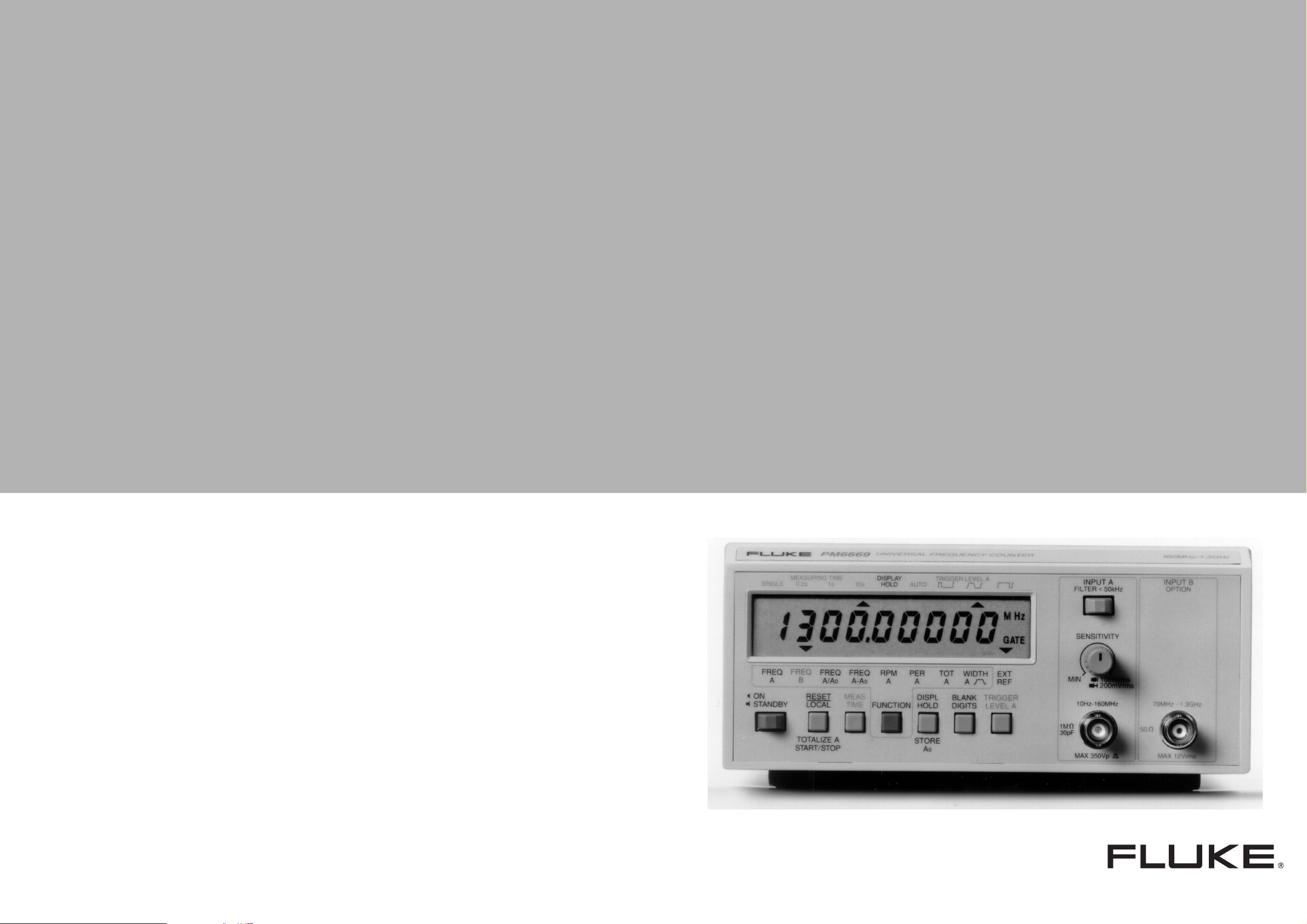
PRODUCT PRESENTATION
General
The PM 6669 is a co mpact, high resol ution, reciproca l Frequency Counter whic h p erf orms man y f un ct io ns. A number of options are avail able i.e. HF-input, GPIB-in te rface,
high stability oscillator, and rechargeable battery for field
use.
A rack-mount kit and a carrying case are also available as
accessories.
F G
IEEE 488 INTERFACE
INCLUDED OPTIONS
PM 9604
PM 9605
PM 9607
PM 9608B
EXT REF INPUT
TALK ONLY
16 8 4 2 1
ADDRESS
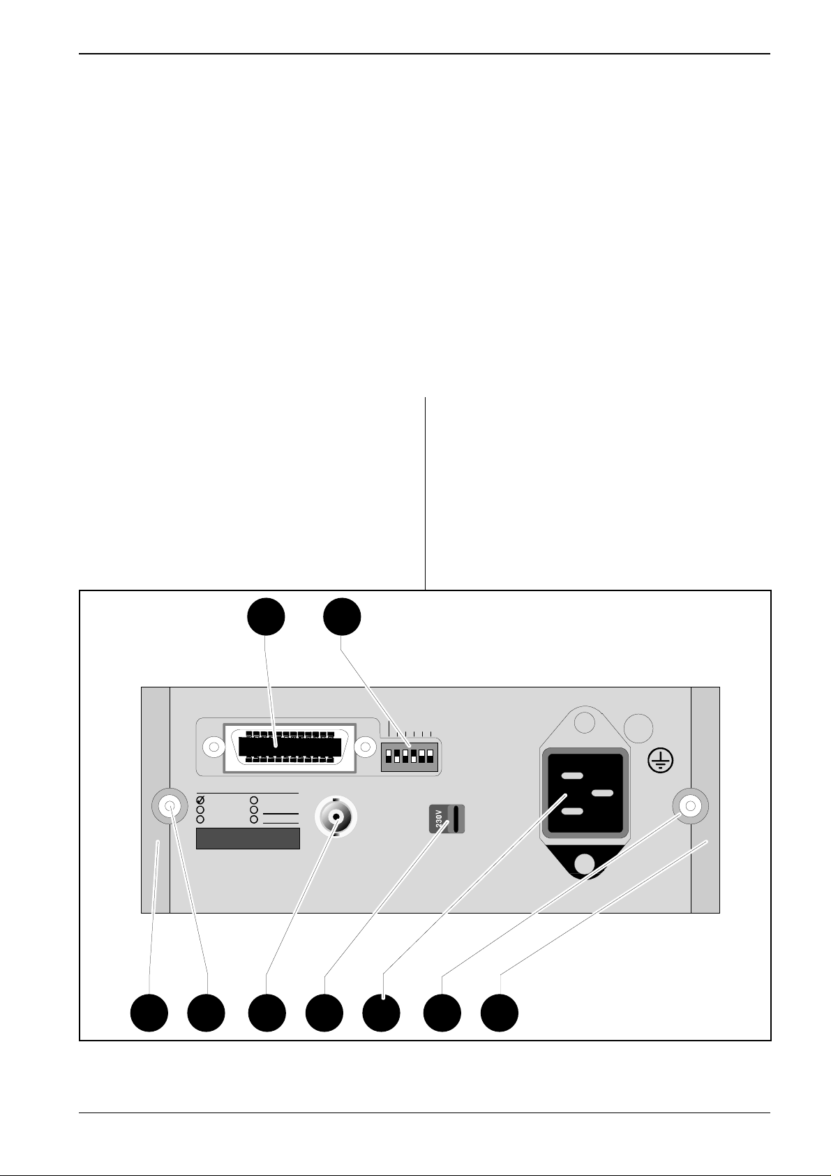
Rear View
A) Rear feet.
B) Screws for removing the cover.
C) External-reference-input, BNC connector.
D) Voltage-range selector.
E) Power-inlet socket.
F) GPIB interface-connector (optional).
G) GPIB address-selector ( option).
SUPPORTED
FUNCTIONS:
SH1,AH1
T5,L4
SR1,RL1
DC1,DT1
ON
E2
OFF
VOLTAGE
SELECTOR
Figure 1
A
Rear View.
10MHz 0.5-15Vrms
B C D
E
THERMAL FUSE IN
MAINS TRANSFORMER
B A
PM 6669 - OPERATORS MANUAL
Page 5
Page: 4 PRODUCT PRESENTATION
H J K L M
MEASURING TIME
SINGLE 0.2s 1s 10s
FREQAFREQBFREQ
ON
STANDBY
N
O
PM 6669
RESET
LOCAL
TOTALIZE A
START/STOP
UNIVERSAL FREQUENCY COUNTER
DISPL
AUTO
HOLD
FREQ
A/Ao
RPMAPERATOT WIDTH
A-Ao
MEAS
FUNCTION
TIME
TRIGGER LEVEL A
DISPL
HOLD
STORE
Ao
BLANK
DIGITS
AA
EXT
REF
TRIGGER
LEVEL A
INPUT A
FILTER<50kHz
SENSITIVITY
MIN
10Hz-160MHz
1M
Ω
30pF
MAX 350Vp
10mVrms
200mVrms
A
INPUT B
OPTION
70MHz - 1.3GHz
50
Ω
MAX 12Vrms
P R S T U V
160MHz/1.3GHz
Figure 2
Front View.
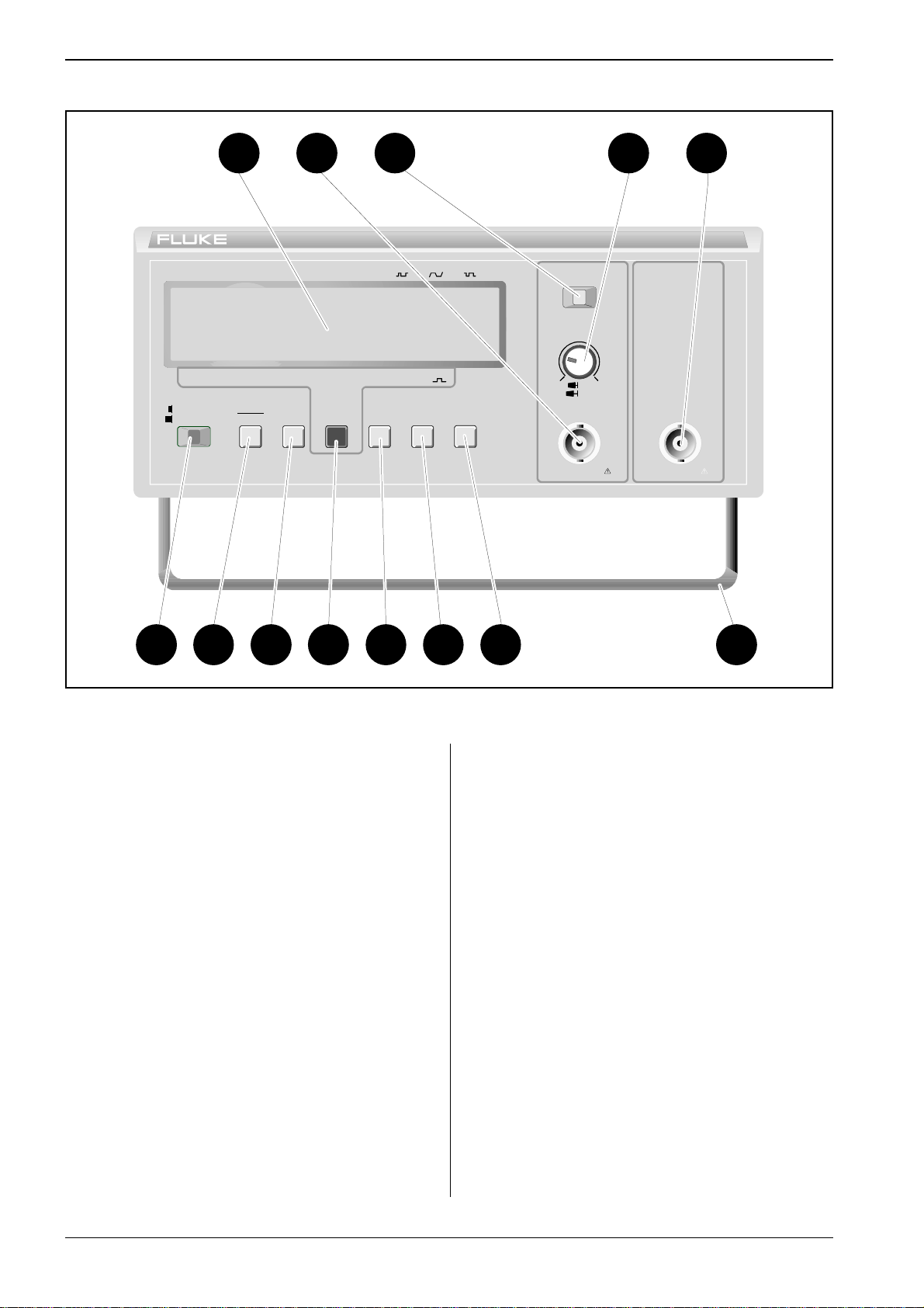
Front View
H) Large LCD-display.
J) Input-A BNC-connector.
K) Sensitivity control with dual-range push-in/pull-out
switch.
L) 50 kHz filter switch (Input-A).
M) Input-B BNC-connector (optional).
N) Power switch.
O) Reset but ton, doubl es as Loca l button if the Fre-
quency Counter is equipped with an GPIB inter-
face. Star ts an d st op s cou ntin g if t he TOT A
function is selected.
P) Measuring-time selector-button. *
R) Fu ncti on-sele ctor bu tton. *
S) Display-hold button. Freezes the display. The but-
ton is also used for storing A
.
0
T) Blank digit s button. B lanks out on e digit for each
depression of the button, from the right to the
left of the display. (No rounding off).
U) Trigg er leve l settin g button.
V) Tilting supp ort.
* The sele cted fun ct ion is i nd icat ed o n the d is play. A
short press on the button moves the cursor one
step to the right. A long press makes the cursor
scroll.
PM 6669 - OPERATORS MANUAL
Page 6

10MHz 0.5-15Vrms
EXT REF INPU T
VOLTAGE
SELECTOR
PM 9604
INCLUDED OPTIONS
PM 9605
PM 9607
PM 9608B
IEEE 488 INTERFACE
TALK ONLY
ADDRESS
16 8 4 2 1
ON
OFF
SUPPORTED
FUNCTIONS:
SH1,AH1
T5,L4
SR1,RL1
DC1,DT1
E2
THERMAL FUSE IN
MAINS TRANSF O RM ER
INSTALLATION Page: 5
INSTALLATION
Unpacking
If the Frequency Counter is cold, leave it in the cardboard
box until it has reached normal roo m te mp erature.
– Lift the Frequency Counter out of the box.
– Remove the polystyrene supports.
– Unpack the Frequency Counter from the plastic bag.
– Reverse the procedure to pack.
Check List
Has the Frequency Cou nt er be en damaged in transport?
If it has, file a clai m with the carrier immediate ly, and notify
the Fluke sa le s & s ervice organizat ion to make repair or
replacement of the instrument easier .
– Check that the package contains the following items in
addition to th e Frequ ency Coun ter:
– This Operators’ Manual
– A power cable with protective earth conductor
– A Battery unit if ordered *)
– An MTCXO oscillator if ordered *)
– A GPIB interface if ordered *)
– An HF-input if ordered *)
*) Labels on the r ear pane l in dicate whic h op tion s
are fitted in your Frequency Counter.
Voltage-Range Selection
Set the Frequency Counter to the local line voltage before
connecti ng it. As delivered the Freque ncy Counter may be
set to either 115 V or 230 V. The setting is indicated on the
voltage range selector on the rear panel.
Figure 4
If the voltage ra ng e se tting is incorrect, set th e se le ct or in
accordance with the loca l vo ltage
power cable to the line.
Location of Voltage Range Selector.
before connecting the
Figure 3
INCLUDED OPTIONS
PM 9604
PM 9605
PM 9607
Options Labe l on Rear P anel.
PM 9608B
Grounding
The Frequency Counter is connected to ground via a
sealed three-core power cable, which must be plugged
into a socket outlet with a protective ground terminal. No
other grounding is permit ted for this Frequency Counter.
Extension cables must always have a protective ground
conductor.
PM 6669 - OPERATORS MANUAL
Page 7
Page: 6 INSTALLATION
Removing the Cover
WARNING: Never interrupt the protective ground-
ing intentionally. Any interruption of the
protective ground connection inside or outside the instrument, or disconnection of
the protective ground terminal is likely to
make the instrument dangerous.
WARNING: When you remove the cover you will ex-
Connecting External
Reference
If you wish to use an exte rnal 10 MHz reference frequency
source, connect it via a BNC-cable to the EXT REF INPUT
on the rear panel of the Frequency Counter.
When the Frequency Counter starts measuring, it automatically dete cts the external ref erence and begins to us e it.
The EXT REF indicato r on th e di sp lay is switch ed on.
Loosen the two screws
using a Pozidrive No. 1 screwdriver
pose live parts and accessible terminals
which can be dangerous to life.
Installing Options
Introduction
The options ordered at the same time as the Frequency
Counter are normally factory-installed. Other options can
be fitted when needed.
The options fit inside the Frequency Counter, but not all at
the same time: The HF-i np ut, the high stabilit y-o sc il la tor
and either of the GPIB-i nterface or the Battery-uni t ca n be
installed in one and the same Frequency Counter.
Calibrating the MTCXO
The MTCXO Time-ba se can easil y be recal ib rat ed to an y
10 MHz reference. To maintain the accuracy of the
MTCXO, use a reference with an accuracy of 3*10-8.
The PM 9691 oven-enclosed oscillator used in Fluke
counters vers ion /.5. meet this requ irement, if calibrat ed.
Preparations
If you remove the cover when count er ha s been swit ch ed
on, the temperature of th e MT CXO will rapi dl y drop ab ou t
10°C. Since the MTCXO must have a stable temperature
when calibrated you must wai t an hou r bet ween removing
the cover and calibrating.
If the counte r has bee n switched off more tha n th ree
hours, you can calibreate it directly .
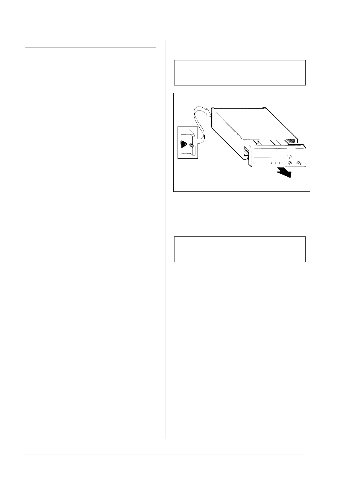
Figure 5
– Make sure that the power cable is disconnected.
WARNING: Although the power switch is in the off
– Loosen the two screws in the rear feet.
– Grip around the front panel and pull the Frequency
Counter out of the cover.
Loosen These Screws to Remove Cover.
position, the line voltage is present on the
printed circuit board.
Calibration Procedure
– Remove the cover from the counter.
– Allow the MTCXO to adapt the new ambient tempera-
ture. (See ’Preparations’.)
– Connect the 10 MHz reference to Input-A.
– Switch ON the coun ter.
– Adjust the sensitivity control so that the counter counts
properly.
– Hold down the CALIB-bu tt on, o n the main prin te d-circ uit
board in the counter, and press the Reset-button.
PM 6669 - OPERATORS MANUAL
Page 8

INSTALLATION Page: 7
CALIB-button
– Wait about 20 seconds, until the display shows
10.0000000 MHz. Now the oscillator is calibrated.
– Switch OFF the counte r a nd d isconn ect the 10 MHz ref-
erence.
Fit the cove r.
Figure 6
Location of the CALIB-Button.
PM 6669 - OPERATORS MANUAL
Page 9
Page: 8 OPERATING INSTRUCTIONS
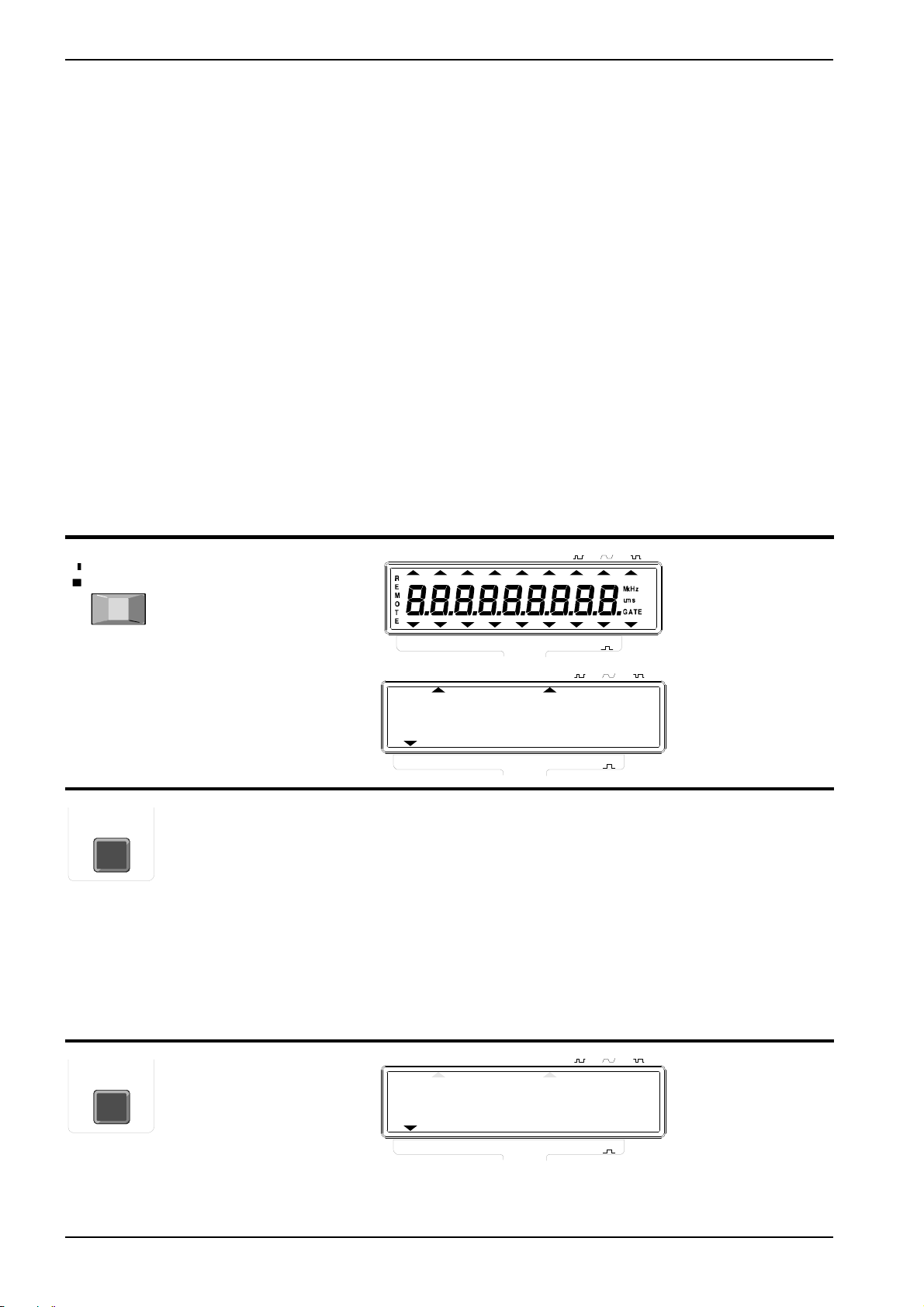
OPERATING INSTRUCTIONS
Using the Frequency Counter
CONTROL OPERATING THE
CONTROL
ON
STAND-BY
FUNCT ION
FUNCT ION
POWER, a two-position
mechanical push-button.
Pressed = ON,
Released = OFF
A short depression of
the FUNCTION key
moves the cursor in the
lower edge of the
display one step to the
right. If the k ey is hel d
depressed, the cursor
will scr oll t o th e rig ht
until re leas ed. When t he
cursor reaches the
rightmos t po sition it
jumps back to the
leftmost po sition and
continues from there.
Move func tion cur sor to
FREQ A
DISPLAY GPIB-CODE
AUTO
PER
AUTO
PER
AUTO
A
A
TRIGGER LEVEL A
WIDTH
TOT
A
A
TRIGGER LEVEL A
0.
WIDTH
TOT
A
A
TRIGGER LEVEL A
EXT
REF
M
kHz
ums
GATE
EXT
REF
kHz
No control
possible but D
gives the same
settings as
after power-ON.
One code for
each func tion,
- see below:
FREQ A
FREQ
FREQ
DISPLMEASURING TIME
HOLD
10s1s0.2sSINGLE
FREQ
A
A
FREQ
A/A
FREQ
B
A/A
FREQ
FREQ
B
RPM
A
A-A
0
0
FUNCTION
DISPLMEASURING TIME
HOLD
10s1s0.2sSINGLE
FREQ
RPM
0
0
A-A
10s1s0.2sSINGLE
A
FUNCTION
DISPLMEASURING TIME
HOLD
PM 6669 - OPERATORS MANUAL
FREQ
0.
FREQ
FREQ
FREQ
B
A
A/A
RPM
0
0
A-A
A
FUNCTION
PER
TOT
A
A
WIDTH
A
EXT
REF
Page 10

OPERATING INSTRUCTIONS Page: 9
FUNCTION AND RANGE HINTS AND COMMENTS
Switches the power ON and OFF. When switched on,
the built in microprocessor switches on all segments
of the display then it runs a power-up test, checking
the measuring-logic of the Frequency Counter before
the counter starts working. This test takes about 2
seconds.
If an error is found, an error code will be displayed.
Try switching the Frequency Counter off and on
again. If error code 01 - 03 persists, call Fluke service. Look on the last page in this manual for Phone
No. and addre ss.
Selects one of the nine measuring functions available. The cursor does not stop at FREQ C if no Input-C HF-
WARNING:The power switch operates on the
secondary side of the transformer. The power cable
must be di scon nect ed fr om t he lin e ou tlet s ocke t if i t
is necessar y to compl etely isol ate the Fr equency
Counter from the line.
Error 01 = RAM memory error
Error 02 = Measuring logic error
Error 03 = Internal bus error
Error OF = Overflow in the counting registers
input is installed.
Reciprocal frequency measurement of the signal at Input-A.
Range:
0.1 Hz to 16 MHz (SINGLE measuring-time)
1 Hz to 160 MHz (0.2, 1, and 10 s measuring-time)
If the signal is sine shaped and the input AC coupled,
the minimum input frequency is 20 Hz (at specified
sensitiv ity) .
PM 6669 - OPERATORS MANUAL
Page 11
Page: 10 OPERATING INSTRUCTIONS
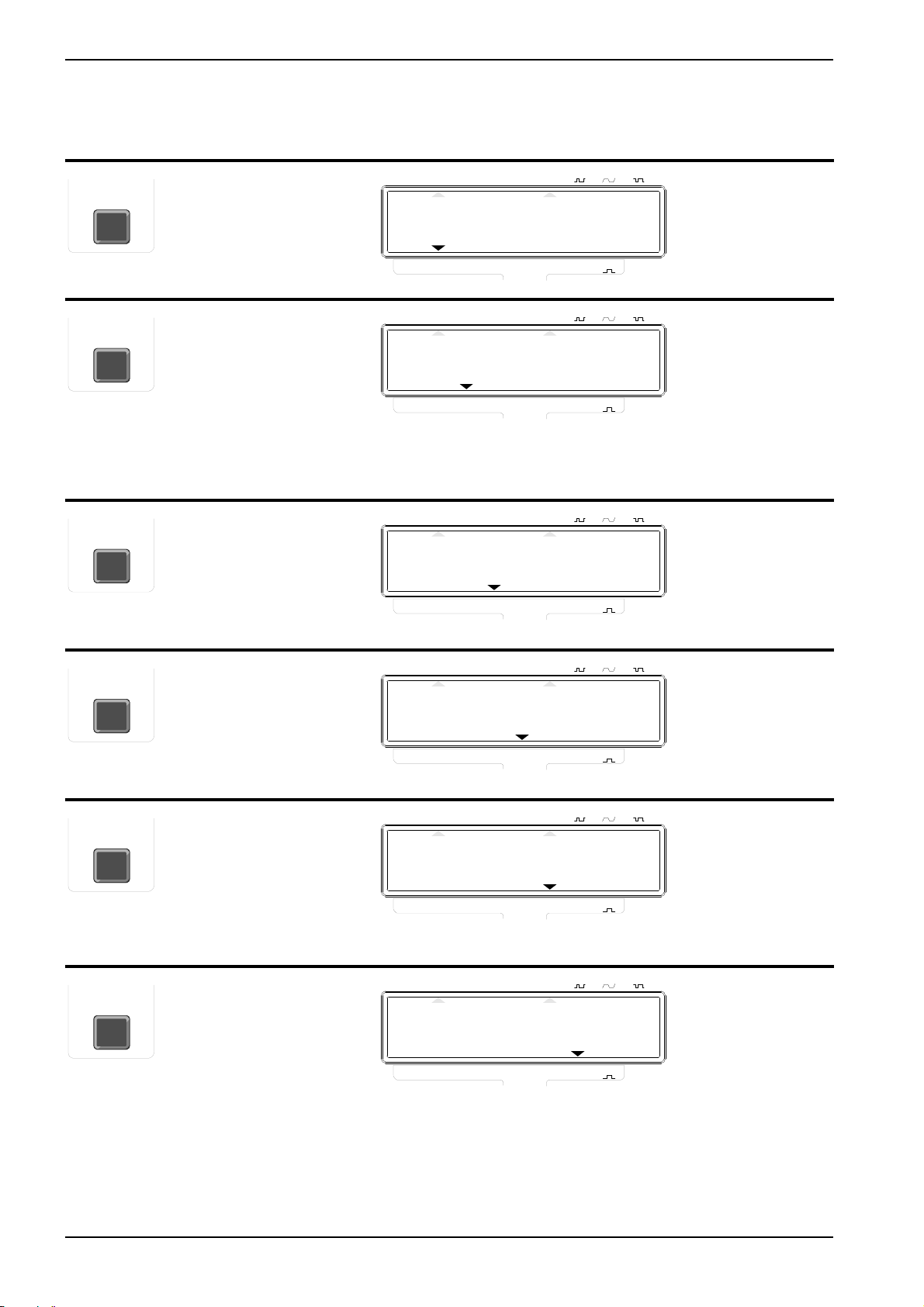
CONTROL OPERATING THE
CONTROL
Move func tion cur sor to
FUNCT ION
FUNCT ION
FUNCT ION
FREQ B
Move func tion cur sor to
FREQ A/A
0
Move func tion cur sor to
FREQ A-A
0
DISPLAY GPIB-CODE
AUTO
TRIGGER LEVEL A
FREQ B
kHz
DISPLMEASURING TIME
HOLD
10s1s0.2sSINGLE
0.
FREQ
A
A/A
A-A
10s1s0.2sSINGLE
A
FUNCTION
DISPLMEASURING TIME
HOLD
A
AUTO
A
TRIGGER LEVEL A
TOT
PER
RPM
0
0
B
WIDTH
A
EXT
REF
Not bus
FREQ
FREQ
FREQ
selectable
0.
FREQ
A
A/A
A-A
10s1s0.2sSINGLE
A
FUNCTION
DISPLMEASURING TIME
HOLD
A
AUTO
A
TRIGGER LEVEL A
TOT
PER
RPM
0
0
B
WIDTH
A
EXT
REF
Not bus
FREQ
FREQ
FREQ
selectable
0.
FREQ
FREQ
FREQ
FREQ
A
A/A
A-A
A
FUNCTION
A
A
TOT
PER
RPM
0
0
B
WIDTH
A
EXT
REF
FUNCT ION
FUNCT ION
FUNCT ION
Move func tion cur sor to
RPM A
Move func tion cur sor to
PER A
Move func tion cur sor to
TOT A
FREQ
FREQ
FREQ
AUTO
TRIGGER LEVEL A
RPM A
DISPLMEASURING TIME
HOLD
10s1s0.2sSINGLE
0.
FREQ
B
A
A/A
RPM
0
0
A-A
10s1s0.2sSINGLE
A
FUNCTION
DISPLMEASURING TIME
HOLD
PER
AUTO
A
TOT
A
TRIGGER LEVEL A
WIDTH
A
EXT
REF
PER A
ms
FREQ
FREQ
0.
FREQ
B
A
A/A
RPM
0
0
A-A
10s1s0.2sSINGLE
A
FUNCTION
DISPLMEASURING TIME
HOLD
PER
AUTO
A
TOT
A
TRIGGER LEVEL A
WIDTH
A
EXT
REF
TOTM A
FREQ
FREQ
0.
FREQ
FREQ
FREQ
B
A
A/A
RPM
0
0
A-A
A
FUNCTION
PER
TOT
A
A
WIDTH
A
EXT
REF
PM 6669 - OPERATORS MANUAL
Page 12

OPERATING INSTRUCTIONS Page: 11
FUNCTION AND RANGE HINTS AND COMMENTS
Reciprocal frequency measurement of the signal at Input-B.
Range:
70 to 1300 MHz (PM 9608B)
The counter divide s the fre quency o n Input-A by a
constant, A
, that is stor ed in the co unter in th e follow -
0
ing way:
1) Connect a signal with the frequency to be stored
to Input-A .
as A
0
2) Select FREQ A.
3) Depress the DISPL HOLD key and hold it de-
pressed until the DISPL HOLD indicator is switched
off again. Now A
4) Select FREQ A/A
is stored.
0
.
0
5) Connect the frequency to be measured to Input-A.
The counter substr acts a co nstant, A0, from the frequency at Input-A. You can read about how to store
A0 in the description for FREQ A/A0.
The cursor does not stop at FREQ B if no Input-B HFinput is installed.
If you select this function without storing A0,
Frequency A will be displayed.
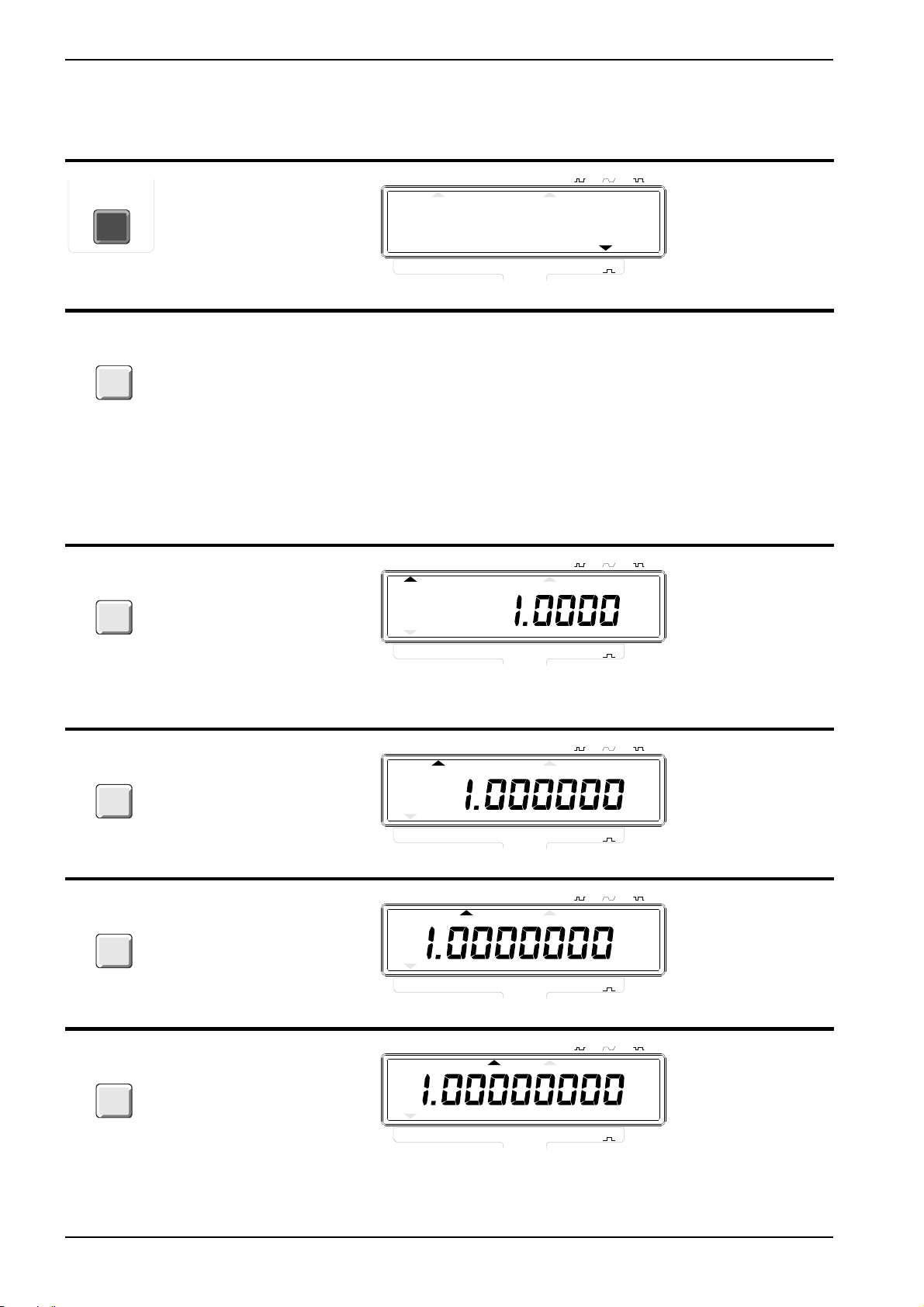
This function is convenient when an oscillator is to be
tuned to the frequency of a reference oscillator. It is
much easier to adjust until the display shows
1.0000000 than 7.122 3678 .
If you select this function without storing A0,
Frequency A will be displayed.
This functio n can e.g. be us ed in a rad io to displa y
the received frequency; Set the intermediate
frequency as the cons tant A
. Select FREQ A-A0 and
0
measure the frequency of the local oscillator, and the
display wil l show th e recei ved frequ ency.
The frequency on Input-A is multiplied by 60 and displayed as Revolutions Per Minute.
Range:
6 RPM to 720 000 000 RPM.
When you select SINGLE, the Frequency Counter
measures one period, the range is: 100 ns to 200
000 000 s (about 6 years and four months!).
When you select 0.2, 1, and 10 s Measuring-time, the
Frequenc y Counter di vide s the inpu t frequen cy by 10
and measures the average period for the No. of cycles in that time.
Range:
8 ns to 1 s.
The Frequency Counter counts the total number of
pulses fed to Input-A. You start and stop the totalizing
with the TOTALIZE START/STOP key (RESET/LOCAL). If you keep this key depressed for more than
one second, the total sum will be reset.
Range:
0 to 1*1015 pulses
Use SINGLE when the input frequency is low. This
shortens th e measur ing time consid erably s ince on e
cycle is measured instead of 10.
k on the display indicates kilo-pulses (1000) and M in-
dicates Me ga-puls es(1 00 0 000).
The Measuring-time indicator is switched off in TOT
A MAN.
PM 6669 - OPERATORS MANUAL
Page 13
Page: 12 OPERATING INSTRUCTIONS
CONTROL OPERATING THE
CONTROL
Move func tion cur sor to
FUNCT ION
MEAS
TIME
MEAS
TIME
WIDTH A
MEAS TIME is operated
in the same way as the
func-tions control, see
page 8.
Move the measuringtime cursor to SINGLE
DISPLAY GPIB-CODE
AUTO
TRIGGER LEVEL A
WIDTH A or
PWIDTH A
ms
DISPLMEASURING TIME
HOLD
10s1s0.2sSINGLE
0.
FREQ
FREQ
FREQ
FREQ
A
A/A
A-A
10s1s0.2sSINGLE
A
FUNCTION
DISPLMEASURING TIME
HOLD
A
AUTO
A
TRIGGER LEVEL A
TOT
PER
RPM
0
0
B
WIDTH
A
kHz
EXT
REF
MTIME <num>
where <num>
is the time in
seconds.
Range:
10 ms to 10 s.
0 = Single
MTIME 0
MEAS
TIME
MEAS
TIME
MEAS
TIME
Move the measuringtime cursor to 0.2 s
Move the measuringtime cursor to 1 s
Move the measuring time cursor to 10 s
FREQ
FREQ
FREQ
FREQ
B
A
A
A
FREQ
FREQ
A/A
FREQ
B
A/A
FREQ
B
A/A
RPM
0
0
0
0
A-A
10s1s0.2sSINGLE
FREQ
A-A
10s1s0.2sSINGLE
FREQ
A-A
10s1s0.2sSINGLE
FUNCTION
DISPLMEASURING TIME
HOLD
0
FUNCTION
DISPLMEASURING TIME
HOLD
0
FUNCTION
DISPLMEASURING TIME
HOLD
RPM
RPM
A
A
A
PER
AUTO
PER
AUTO
PER
AUTO
A
A
A
TOT
A
TRIGGER LEVEL A
TOT
A
TRIGGER LEVEL A
TOT
A
TRIGGER LEVEL A
WIDTH
A
WIDTH
A
WIDTH
A
kHz
kHz
kHz
EXT
REF
EXT
REF
EXT
REF
MTIME 0.2
MTIME 1
MTIME 10
FREQ
FREQ
PM 6669 - OPERATORS MANUAL
FREQ
FREQ
B
A
A/A
RPM
0
0
A-A
A
FUNCTION
PER
TOT
A
A
WIDTH
A
EXT
REF
FREQ
FREQ
Page 14

OPERATING INSTRUCTIONS Page: 13
FUNCTION AND RANGE HINTS AND COMMENTS
The counter measures the positive pulse width of the
signal on Input-A.
Range:
100 ns to 200 000 000 s.
The set Measuring-time controls the time during
which the main gate is opened, allowing pulses to enter the coun ting log ic. A lon ger Measu ring-t ime give s
higher r eso luti on re adou ts wi th m ore d igit s di spla yed.
The time the gate is open is no t exactl y the pre set
Measuring-time, because the Frequency Counter synchronizes the measurement with the input signal in order to measure complete periods. If the period of the
input signal is longer than the set Measuring-time, the
main gate doe s not clos e again unti l the per iod is
completed.
For PER A and WIDTH exactly one period or one
time interval is measured. The minimum result possible is 100 ns.
The display time will be 100 ms.
When set to SINGLE, FREQ A and, RPM A, the
Measurin g-tim e is one c ycle of the in put sign al or
3 ms, whichever is longest. When set to SINGLE and
FREQ B, the Measuring-time is 3 ms.
If you are interested in the negative pulse width
instead; f irst meas ure t he p eriod and mak e a no te of
the result, then measure the pulse width and
substract it from the period reading.
If you wish to do one measurement instead of
repetitive measurements, see DISPL HOLD.
The input frequency is limited to 16 MHz for FREQ A,
PER A, and RPM A.
If external referen ce is used , the EXT RE F indica tor
will not be switched-on until after the first
measurement.
A Frequency-A measurement will result in 6-7 digits
on the displa y.
A Frequency-A measurement will result in 7-8 digits
on the displa y.
A Frequency-A measurement will result in 8-9 digits
on the displa y.
PM 6669 - OPERATORS MANUAL
Page 15
Page: 14 OPERATING INSTRUCTIONS
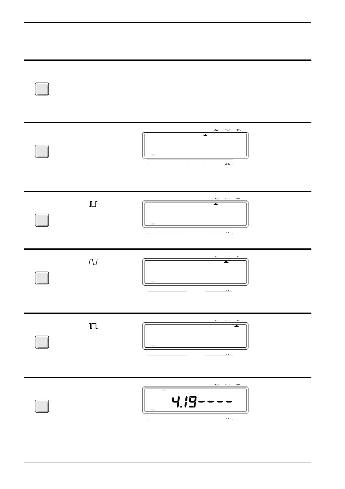
CONTROL OPERATING THE
CONTROL
The TRIGGER
TRIGGER
LEVEL A
TRIGGER
LEVEL A
TRIGGER
LEVEL A
LEVEL A control is
operated in the same
way as the functions
control, see page 8.
Move Trigg er Leve l A
cursor to AUTO.
Move Trigg er Leve l A
cursor to
DISPLAY GPIB-CODE
One code for
each trigger
level offset.
See below.
AUTO
TRIGGER LEVEL A
TLO AUT
kHz
DISPLMEASURING TIME
HOLD
10s1s0.2sSINGLE
0.
FREQ
FREQ
FREQ
FREQ
A
A/A
A-A
10s1s0.2sSINGLE
A
FUNCTION
DISPLMEASURING TIME
HOLD
A
AUTO
A
TRIGGER LEVEL A
TOT
PER
RPM
0
0
B
WIDTH
A
kHz
EXT
REF
TLO POS
TRIGGER
LEVEL A
TRIGGER
LEVEL A
BLANK
DIGITS
Move Trigg er Leve l A
cursor to
Move Trigg er Leve l A
cursor to
Each depression of the
BLANK DIGITS key
blanks out on e digit
starting from the right
(Least Sig-nificant Digit).
When all digi ts are
blanked out, the next
depression removes the
blanking.
FREQ
FREQ
FREQ
FREQ
0.
FREQ
B
A
A/A
RPM
0
0
A-A
10s1s0.2sSINGLE
A
FUNCTION
DISPLMEASURING TIME
HOLD
PER
AUTO
A
TOT
A
TRIGGER LEVEL A
WIDTH
A
kHz
EXT
REF
TLO SYM
FREQ
FREQ
0.
FREQ
B
A
A/A
RPM
0
0
A-A
10s1s0.2sSINGLE
A
FUNCTION
DISPLMEASURING TIME
HOLD
PER
AUTO
A
TOT
A
TRIGGER LEVEL A
WIDTH
A
kHz
EXT
REF
TLO NEG
FREQ
FREQ
0.
FREQ
FREQ
FREQ
B
A
A
FREQ
A/A
FREQ
B
A/A
RPM
0
0
0
A-A
10s1s0.2sSINGLE
FREQ
A-A
FUNCTION
DISPLMEASURING TIME
HOLD
0
FUNCTION
RPM
A
A
PER
AUTO
PER
A
A
TOT
A
TRIGGER LEVEL A
TOT
A
WIDTH
A
WIDTH
A
kHz
EXT
REF
EXT
REF
Not bus
controll able
PM 6669 - OPERATORS MANUAL
Page 16

OPERATING INSTRUCTIONS Page: 15
FUNCTION AND RANGE HINTS AND COMMENTS
The normal trigger level of the AC-coupled Input-A is
0 V. This is ideal for symmetrical signals like sinewaves, since their average DC component is 50 % of
Vp-p.
Non-symmetrical signals however, might fail to trigger
if the trigger level is 0 V. Therefore there are three
trigger l evel set tings avai labl e; o ne for smal l du ty fac tors, one for symmetrical wave forms and one for
large duty factors.
When set to Auto the counter first tries the trigger
level for symmetrical signals. If that does not work, it
tries the ot her setti ngs.
Auto does not work if TOT A is selected.
Range: Auto works with input frequencies from 100
Hz and up.
Use this setti ng if the du ty factor is below 25 %.
A positive offset vo ltage is added to th e trigger level.
It is often poss ible f or the coun ter to tri gger on
unsymmetrical signals even though the symmetrical
triggering is sele cted, pro vided th at the sen sitivi ty is
high enough. This however, gives poor noise
immunity.
If you don’t know the duty factor of the input signal,
select Auto. If that does not work (too low input
frequency) do as follows;
a) Set the se nsitiv ity to max .
b) Select Trigger level .
c) Reduce the sensitivity until the gate indicator stops
blinking.
d) Check if trigger level or makes the gate
indicator start blinking again. If it does, leave the
trigger level in that position, otherwise return to trigger
level .
e) Turn the sensitivity down until the gate indicator
stops
blinking, then up slightly until it starts again. The
trigger
level is now correct.
Use this setti ng if the du ty factor is between 2 5 %
and 75 %.
The trigger level is 0 V.
Use this setti ng if the du ty factor is below 75 %.
A negative offset vo ltage is added to th e trigger level.
Each digit that is blanked out is removed and replaced by a -. The numerical value on the display is
not rounded off. The blanking is cleared by reset,
changing settings or when all digits are blanked and
you press the BLANK DIGITS key once more.
This function is used to blank the display of irritating,
unstable d igit s.
PM 6669 - OPERATORS MANUAL
Page 17

Page: 16 OPERATING INSTRUCTIONS
CONTROL OPERATING THE
CONTROL
RESET
LOCAL
TOTALIZE A
START/STOP
DISPL
HOLD
STORE
0
A
INPUT A
10Hz-160MHz
1M
Ω
30pF
MAX 350Vp
RESET/LOCAL, a short
press is enough for
Reset. When the remote
indicator is on, a press
will cause the counter to
switch back to LOCAL,
i.e. control from the front
panel.
TOTALIZE
START/STOP, one
press star ts tota lizing ,
the next press stops.
Switches ’on’ or ’off’
DISPL HOLD when depressed.
Connect th e signal to
INPUT-A via a BNCcable.
DISPLAY GPIB-CODE
X starts a new
measurement.
GATE OPEN
starts and
GATE CLOSE
stops Totalize
MAN.
AUTO
PER
A
TRIGGER LEVEL A
0.
WIDTH
TOT
A
A
kHz
M
ums
GATE
EXT
REF
Not bus controllable, but
Free-run OFF
will give a
similar fu ncti on;
See GPIB-bus
operation.
FREQ
DISPLMEASURING TIME
HOLD
10s1s0.2sSINGLE
FREQ
FREQ
FREQ
A/A
B
A
RPM
A
A-A
0
0
FUNCTION
INPUT B
OPTION
70MHz - 1.3GHz
Connect th e signal to
INPUT-B via a BNCcable.
50
Ω
MAX 12Vrms
PM 6669 - OPERATORS MANUAL
Page 18

OPERATING INSTRUCTIONS Page: 17
FUNCTION AND RANGE HINTS AND COMMENTS
When reset is depress ed, the di splay an d coun ting
registers are clea red. When reset is releas ed, a new
measurement is started. The Measuring-time-, Functionand d ispl ay hol d- s ettin gs a re no t affe cted .
If the TOT A function is selected, the RESET/LOCAL
key functions as a START/STOP key. One press
starts the counting an d the next press st ops it. A long
depressi on re sult s in rese t.
Display hold f ree zes th e di spla y, b ut not until the
measurement in process has been finished. A new
measurement can always be initiated via the RESET
key.
Store A
tions FREQ A/A
described under FUNCTIONS, FREQ A/A
is used to stor e the cons tant use d in func-
0
and FREQ A-A0. The procedure is
0
.
0
Use this input for all functions except FREQ B.
Range: 10 Hz to 160 MHz
Impedance: 1 M //30 pF
Min. pulse du ration:4 ns
When the counter is controlled from the GPIB-Bus,
the LOCAL key can be disabled via the ’Local Lock
out’ command.
At higher fre quencies ; use a 50 Ω termination type
PM 9585 to avoid interference caused by impedance
mis match.
The illustr ation belo w shows whi ch functio n block
each of the inpu t contr ols affe ct.
Sensitivity
60 mV
40 mV
20 mV
0 30 MHz 120 MHz 160 MHz
AC Spec.
Typically
DC Spec.
2
0
H
z
Max voltage
350 V
DC+AC
peak
8 V
RMS
0 440 Hz 1 MHz 120 MHz
This is the HF-input which must be used when the
FREQ-B function is selected. If the Frequency
Counter does not include the Input-B option, the BNCconnector is replaced by a plastic plug.
Range:
70 to 1300 MHz.
Impedance:
50Ω
Sensitivity:
10 mV
15 mV
up to 900 MHz,
RMS
900-1100 MHz
RMS
and 40 mVRMS a bove.
Max voltage:
12 V
RMS
Trigger level offset
Attenuator
Input-A
Sensitivity range switch
Figure 7.
Input circuit block diagram.
Filter
Counting
logic
Sensitivity
control
PM 6669 - OPERATORS MANUAL
Page 19

1
s
Page: 18 OPERATING INSTRUCTIONS
CONTROL OPERATING THE
CONTROL
INPUT A
SENSITIVITY
MIN
10mVrms
200mVrms
INPUT A
FILTER<50kHz
Pull the SENSITIVITY
knob to switch to AC
coupling. Depress the
knob to switch to DC
coupling.
NOTE: The
potentiometer controls
the sensitivity when ACcoupled and Trigger
Level when DC-coupled.
Turn the knob clockwise
to increas e and coun ter
clockwise to decrease
the trigger level or
sensitivity.
One two-position switch.
Depress to switch on
the FILTER and relase
to switch it off.
DISPLAY GPIB-CODE
Not adjust able
from the bus.
Not bus
controll able .
EXT REF INPUT
0MHz 0.5-15Vrm
Connect an external
10 MHz frequency
source to the BNCconnector on the rear
panel of the Frequency
Counter marked EXT
REF INPUT.
FREQ
AUTO
TRIGGER LEVEL A
Not bus
DISPLMEASURING TIME
HOLD
10s1s0.2sSINGLE
controll able .
kHz
M
u
ms
0.
GATE
FREQ
FREQ
FREQ
A/A
B
A
RPM
0
0
A-A
A
FUNCTION
PER
TOT
A
A
WIDTH
A
EXT
REF
PM 6669 - OPERATORS MANUAL
Page 20

OPERATING INSTRUCTIONS Page: 19
FUNCTION AND RANGE HINTS AND COMMENTS
For frequency-, period-, and ratio measurements:
Select AC coupling and set the sensitivity so that the
hysteresis band of the Frequency Counter is about
half the ampl itude of the signal.
For time measurements:
Select DC coup ling and set t he t rigge r lev el t o the de-
sired leve l using th e 1 V/div istion s cale on th e front
panel.
The filter works on Input-A where it suppresses signals with higher frequencies than 50 kHz.
Filter suppression:
40 dB at 1 M Hz
The Frequency Counter automatically detects if a suitable signal is connected to the EXT- REF Input-connector.
Suitable signal:
10 ± 0.1 MHz, 0.5 to 15 V
Sine wave.
RMS
1. S et the se nsitiv ity knob fully cou nter cl ockwise .
2. T urn it unti l the input tr iggers .
3. Continue turning to the 20 mV
position, or to the
RMS
position w here the di splay tu rns uns table du e to noise.
4. S et the kn ob to the po sition i nbetwee n these two
points.
You will have a stable reading.
If the sensitivity is too high, the Frequency Counter
will be trigge red by nois e and inte rferen ce instead of
by the signal.
The filter ca n also be us ed to supp ress H Finterferen ce on sign als wit h higher fr equen cies tha n
50 kHz, b ut the n the sens itiv ity of the inp ut wi ll b e
reduced.
NOTE: Nev er use th e filter when meas uring TIME A-B
since the filter delays the signal on Input-A.
Use external reference when the measurement
requires ult ra-h igh s tab ilit y.
The Frequ ency C ounte r mu st st ill have the i nter nal
time base even if an external reference frequency is
used.
If single is selected, the EXT REF indicator on the
display is not swit ched o n unti l af ter t he fir st
measurement.
PM 6669 - OPERATORS MANUAL
Page 21

Page: 20
Battery Unit
Operation
When a battery unit is installed, the counter can operate
for 3 hours wi thout mains supp ly. The display st arts blinking shortly be fore the battery is disc harged.
The counter charges the battery automatically when connected to the mains, no mat te r how th e Power-switch is
set. Charging a discharged battery to 75 % of full capacity will take 7 hours, and to full capacity, 24 hours.
If the coun te r i s co nnected to the mai ns and switched
on, it will not switch to battery operation if you disconnect the mains. You must first switch the coun te r O F F
with the power switch, then ON again before the battery
unit supplies the counter.
Battery Care
The capacity of the rechargeable battery degrades if the
counter is not powered by the battery frequently. To
keep the battery from degrading, cycle the batte ry, from
fully charged to fully discharged, occasionally.
The capacity of a degraded battery can be restored by
cycling the bat te ry a number of times, but a restored battery will never reach the capacity of a new one.
Error Codes
The counter can disp la y th e fo ll owing error codes if
something goes wrong.
Error OF Overflow in the counting registers.
Select a shorter Measuring-time if you
get this error code, unless the counter
is set to TOTALIZ E, then you must
press reset and start again from zero.
Error 01 RAM memory error
Error 02 Measuring logic error
Error 03 Internal bus error
If the counter sho ws on e of these error codes, try switching the counter off and on again. If erro r code 01-03 persists, call Fluke service. Look on the last page in this
manual for Phone No. and address.
If you must store your counte r for so me time wit ho ut using it, store it in a cool and dry place. Leave the counter
with the mains cable connected if possible. If not, don’t
disconnect the mains cable until the battery is fully
charged, then charge the battery for at least 8 hours
every 3 months .
CAUTION: Prolonged storage or use of the counter
at temperatures above +40°C shortens the
life of the battery.
The battery will freeze if it is not sufficiently
charged when stored at a low temperature.
75% charge is sufficient for -40°C.
PM 6669 - OPERATORS MANUAL
Page 22

GPIB-INTERFACE OPERATION Page: 21
GPIB-INTERFACE OPERATION
Introduction
The PM 6669 can be controlled by a computer (controller) via the GPIB-interface o pt ion, P M 960 4. All functions
that can be controlled from the front panel can also be
controlled via th e bus in a similar way, except select io n
of measuring functions FREQ A/A
filter, the sensitivity cont rols, and the power switch. T he
additional micro-processor on the interface board has
made it poss ible to add func tions. You can obtain continuousl y va riable Measuring -time, bus-learn, h ig hspeed-dump etc., bu t th es e fu nc ti on s are onl y ac ce ssible via the bu s.
To select a function, you send a command to the
counter. We have chosen the text on the front panel as
commands, wherever possible, in order to make them
easy to remember. E.g. the command to select Frequency-B is FREQ B and the command to select Period
A is PER A.
NOTE: The characters in a command can be in both up-
per and lower case.
, and FREQ A-A0, the
0
What Can I Do Using the
Bus?
All the capabilities of the interface for the PM 6669 are
explained below. If you want a complete description of
all GPIB-interface functions, read the ’Fl uke In strumentation-Systems Reference-Manual’.
Summary
Description Code
Source ha ndshak e SH 1
Acceptor handsh ake AH1
Control function CØ
Talker Function T5
Listener function L4
Service request SR1
Description Code
Remote/local function RL1
Parallel poll PPØ
Device c lear func tion DC1
Device trigger function DT1
Bus drivers E2
Source and Acceptor Handshake SH1, AH1
SH1 and AH1 simply means th at the counter can exchange data with other instruments or a controller, using
the bus handshake lines; DAV, NRFD, NADC.
Control Function, CØ
The counte r does not function as a co ntroller .
Talker Function, T5
The counter can send responses and the results of its
measurements to other devices or to the controller. T5
means that it has the following functions:
– Basic talk er.
– Talk only mode.
– It can send out a status byte as response to a serial
poll from the controller.
– Automatic un-addressing as talker when it is addressed
as a listener.
Listener Function, L4
The counter c an receive programming in st ructions from
the controller. L4 means the following functions:
– Basic list ener.
– No listen only.
– Automatic un-addressing as listener when addressed
as a talker.
Service Request, SR1
The counter can call for attention from the contro ll er e. g.
when a measurement is completed and a result is available.
PM 6669 - OPERATORS MANUAL
Page 23

Page: 22 GPIB-INTERFACE OPERATION
Remote/Local, RL1
You can control the counter manually (locally) from the
front panel, or remotely from the controller. The LLO, local-lock-out functi on , ca n disa bl e the LOCAL button on
the front panel.
Parallel Poll, PPØ
The counter does not have any parallel poll facility.
Device Clear, DC1
The controller can reset the counter, forcing it to default
settings, via int erf ac e me ss ag e DCL (Device clear) or
SDC (Selective Device Clear).
Device Trigger, DT1
You can start a new measurement from the controller
via interface message GET (Group Execute Trigger).
Bus Drivers, E2
The GPIB interface has tri-state bus drivers.
Connecting the Controller
The bus interface connector is on the rear panel of the
counter. If your counter does not have any connector,
you must install the GPIB-interf ace op tion .
Address
Switch
settings
Address
Switch
settings
Address
Switch
settings
0 00000 10* 01010 20 10100
1 00001 11 01011 21 10101
2 00010 12 01100 22 10110
3 00011 13 01101 23 10111
4 00100 14 01110 24 11000
5 00101 15 01111 25 11001
6 00110 16 10000 26 11010
7 00111 17 10001 27 11011
8 01000 18 10010 28 11100
9 01001 19 10011 29 11101
30 11110
* Factory setting.
NOTE: 31 is the bus command for "Untalk" and should
not be used. If 31 is selected the counter will
work as if address 0 is selected.
Talk-Only
The leftmost switc h in the add ress switch block is the
T ALK ONLY switch. If you set it to ’1’, the counter will
output measurement results on the bus continuously. It
will not react to any incoming commands.
GPIB connector Address switch
ON
OFF
VOLTAGE
SELECTOR
SUPPORTED
FUNCTIONS:
SH1,AH1
T5,L4
SR1,RL1
DC1,DT1
E2
THERMAL FUSE IN
MAINS TRANSFORMER
INCLUDED OPTIONS
Figure 8
PM 9604
PM 9605
PM 9607
IEEE 488 INTERFACE
PM 9608B
TALK ONLY
EXT REF INPUT
10MHz 0.5-15Vrms
ADDRESS
16 8 4 2 1
GPIB conn ecto r a nd add res s sw itch, the
numbers above the switches indicate the significanc e of each swi tch.
Connect the cont rol le r via an IEEE-4 88 cable to the bus
connector. If you use IEC-625 cables, an adapter is
available, see ord eri ng information at the end of th is
manual.
Giving the Counter an Address
The counter must have a unique address so that the
controller ca n communicate with it . Th e a ddress is selected by setting switches to the binary equivalent of the
address you want. The switches are located to the right
of the interface connector. The OFF position means 0
and the ON position means 1.
This setting may only be used if the counter is connected to a ’Listen only’ device such as a printer. Set the
switch to ’0’ when yo u w ant normal bus comm u nication.
Talk only is set to ’0’ on delivery .
The counter is now ready for bus control.
Checking the Communication
To check if the counter and the controller can communicate, address the counter and execute the following sequence: (The programming example is for an HP-85
controller.)
Type on Controller: This Should Happen.
REMOTE 710 The remote indicator should
be switched on.
OUTPUT 710;"ID?" Ask for the counter identity.
ENTER 71 0;A$ Input result from counter.
DISP A$ The response on the
display of the controller is
the identity of the counter.
If everything is OK, the counter will identify itself as:
PM6669/YZW/MN
where:
Y = 4 if the counter has an HF-input, oth erwi se 0.
Z = 3 for MTCXO, otherwise 1
W = 6 (GPIB-bus is installed)
M = Revision No. of counte r firmware
N = Revision No. of GPIB-bus firmware
PM 6669 - OPERATORS MANUAL
Page 24

GPIB-INTERFACE OPERATION Page: 23
Two Ways of Programming
The simplest way of programming the counter is by
manually setting up the measurement you want from the
front panel of the counter, then let the controller ask the
counter how it is se t up. The data the con troller gets
from the counter can be used to set up the same measurement over and over again. This method is called ’Buslearn’ and will be explained later.
The other method is to make a prog ram messa ge where
each step of the set-up is separately specified.
Programming Check-List
Check that the following steps have been taken to ensure correct programmin g of the instrument.
Normally only the six first steps must be programmed.
– Do you know the current setting of the counter? If not,
send device clear ’D’ to get the default settings.
– Select Measuring-function;
(Default: Frequency-A.)
– Select Measuring-time;
(Default: 0.2 s.)
– Select Trigger-level offset;
(Default: Positive)
For advanced programming, check the following steps.
– Select Trigger-slopes;
(Default: AUTO)
– Set Output separator;
(Default: LF.)
– Set EOI mode;
(Default: OFF.)
– Set service request(SRQ) -mask;
(Default, No SRQ.)
– Select Free-Run on or off;
(Default: ON.)
– If Free-Run is off, select Time-Out if desired;
(Default: Infinite, programmed as 0 s.)
– Set Output-mode;
(Default: Normal output format, High-speed dump OFF
and MTCXO compensation ON.)
All functions and commands in the checklist will be explained la ter.
Syntax
What is a Programming Command?
A programming command consists of a header, addressing the func ti on you want, and a body instructing th e
function what to do.
EXAMPLE:
TRGSLP
HEADER, addressing
Trigger Slope
NOTE: Some programming commands consists only of
the Header, e.g. trigger com mand ’X ’.
What is a Programming Message?
A programming message is a number of programming
commands with separators between them. E.g. the commands necessary to set up a measuremen t.
EXAMPLE: PER A;M TIM E 0
Input Separator
All communication between the counter and the controller uses sequences of ASCI I-c ha racters terminated by a
separator. Input separators are the separators sen t by
the controller. They are used in four different places:
Between
header and
body
<space> <c omma> <s emicolon> <linefeed>
The separators in th e ex ampl e ab ov e are the ones normally used in respective place. The counter will however
accept any one in any place.
The following separators will also work in any of the four
places: colon, CR, ETB, ETX, the sep ara tor selected as
output separator, as well as an active EOI-signal.
As unit
separator
between
bodies
FREQ A,B:FRUN ON↵
POS
BODY, switching slope
to positi ve
Between
Program
commands
To end a
program
message
NOTE: You only have to program the changes from the
previous set-up.
PM 6669 - OPERATORS MANUAL
Page 25

Page: 24 GPIB-INTERFACE OPERATION
Order of Commands in a Program
Message
Normally, the programming commands in a programming message can be placed in any order.
However, the following commands must always be
placed at the end of a program message since any command sent after them will disable the selection:
INPA? MEAC? FNC? X
BUS? ID? OUTM 4
These commands will be ignored if found anywhere but
in the end of a message.
<number>
In some program commands, the body is replaced by
the term <number> or <num> . Here you must en ter a numerical value. <numb er> can be en te red in any format
you like e.g. 1.23 can also be entered as
0.000000123
digits than the counter needs, your entry will be truncated. The counter will stop if an entry is out of the counters range. To proceed, the status mes sa ge ’Programming error’ must be reset , se e ’Status byte’.
107 or 1230000∗10-6. If you enter more
∗
Selecting Output Separator
Output separators terminate messages from the counter
to the controller. The separator needed is different for dif ferent controllers; see the Operators’ Manual for your
controller.
At power on, the output separator of the counter is linefeed ’LF’ (10
The output separator can be changed by sending SPR
<number> to the counter. <number> is the decimal
value of the ISO (ASCII)-code for th e de si red sep ara to r.
It can be 0-26, 28-31, ESC code, 27, is not accepted.
Only one <number> can be entered as separator. If you
want the combination of CR+L F (13
lected by ’SPR 255’.
EXAMPLE:
SPR 13 changes the output separator to CR
SPR 255 changes the output separator to CR+LF
The counter can signal EOI together with the last output
separator in responses and output data.
EOI ON switches on the function.
EOI OFF switches it off.
Default setting is EOI OFF.
The selected separat or and EOI will not be altered by
LOCAL from the front panel nor by LOCAL or ’Device
clear’ from the bus.
decimal
).
dec
+ 10
), it is se-
dec
How to Select Function
Standard Functions
Functions are selected by sending the appropriate function command to the counter, e.g. FREQ A. The space
between FREQ and A indicates the input separator t hat
you always must insert.
Function Command Comment
Frequency A FREQ A Default
Frequency
B*
Frequency A/A0— Make a FREQ A
Frequency A-A0— Make a FREQ A
RPM A RPM A
Period A PER A
Totalize A
Manually TOTM A See ’Totaliz e start/s top’.
Pulse-width A WIDTH A The counter will also accept
The function cursor on the display of the counter will
jump to the selected fu nc ti on.
Only possible if Input-B option, PM 9608B is installed.
*
FREQ B
measurement and then
perform the r atio calc ulat ion
in the controller.
measurement and then
calculate the frequency
difference in the controller.
PWIDTH A.
Selecting Measuring-Time
The Measuring-time can be set to any valu e be twe en
10 ms and 10 s, or SINGLE-measuring. Any value below 10 ms will be interpreted as SINGLE. Values above
10 s will be out of range and cau se an e rror. The program command is MTIME <number>. Al ways enter the
Measuring-time in seconds. The entered value will be
trunkated to the nearest 10 ms increment.
Meas
Time.
0.2 s MTIME 0.2 Default
10 m s MTI ME 0 .0 1 You will not be able to see the
7.34567 s MTIME 7.34567 The Measuring-time will be
2 ms MTIME 0.002 Out of range. Measuring
SINGLE MTIME 0 A display time of 50 ms is
25 s MTIME 25.0 Out of range and error, the
Command Comment
gate indicator blinking if the
Measuring-time is below 50 ms
7.34 s.
time will be SINGLE.
set so that you can see the
Gate-indicator.
counter wil l stop. It can
indicate programming error
by sending an SRQ if
selected in the SRQ-mask.
PM 6669 - OPERATORS MANUAL
Page 26

GPIB-INTERFACE OPERATION Page: 25
The Measuring-time cursor on the display will indicate
0.2 s for all programmed Measuring-times except SINGLE, which will be indicated as usual.
Selecting Tr iggering
The trigger level can be sel ec te d in the same way as
from the front panel.
Trigger-level
offset Code Comment
Auto TLO AUT Default
TLO POS
TLO SYM
TLO NEG
The trigger-level cursor on the front panel willindicate the
setting.
Trigger slope Command Comment
Positive TRGSLP POS Default
Negative TRGSLP NEG Negative slope is only
availabl e via the bu s
and is used when yo u
want to measur e the
negative Pulse-width.
When the counter switches to local, the trigger slope will
switch back to positive. Trigger slope is not indicated on
the displa y.
Totalize Start/Stop
When TOT A is selected, the gate is opened and closed
by the controller instead of by press ing the button on th e
front panel. To start the counting after selecting T OTM A,
the gate must be opened.
T otalize Command Comment
Start GATE OPEN Starts counting.
Stop GATE CLOSE Stops counting.
Default.
NOTE: Multiple GATE OPEN/GATE CLOSE will accu-
mulate the results in the counting registers.
Any other command but GATE OPEN/GATE
CLOSE will stop the totalizing and reset the
counting registers to zero.
Free-Run/Triggered
The counter can work in two different ways:
1. Free-Run, where it starts a new measurement as
soon as the previous measurement is finished.
The first measuring result that is ready after the
counter receives a read command, will be sent
to the controller. When the result has been read,
the output buffer is r eset to z ero u ntil a new result is ready. One and the same measuring result can only be read once.
2. Triggered, where the counter waits for trigger com-
mand GET or ’X’ from the controller before it
starts a measurement. When the measurement
is completed, the counter will wait until the controller reads the measuring results, then the output buffer is reset. The function is the same as
when Displ Hold is selected from the front panel
and you start a new measurement by pressing
the reset button.
Free-Run Command Comment
Off FRUN OFF This function is sometimes
called Triggered-Mode, so the
TRIG ON command will also
result in the same func tion.
On FRUN ON TRIG OFF gives the same
result. Default.
Free-Run ON or OFF will not be indicated on the display. When the counter switch es to LOCAL , Fre e-Ru n
will always be ON but when the counte r switches back
to remote, it will return to its previous ly prog rammed settings.
Time-Out
When Free-Run is swi tc he d off it is possible to set a
time-limit (time-out) between the start of a measurement
and the time wh en a result is expected to be ready. If no
result is achieved before the set time is out, the counter
can output a Service Request, SRQ. Time-Out must be
selected in the SRQ-mask; see ’Servi c e Request’. The
programming command is TOUT <number>. The timeout
can be set to any value between 100 ms and 25.5 s, the
minimum increment is 100 ms.
Time-Out Command Comment
100 ms TOUT 0.1 Time-Out is only intended to
be used with Free-Run off*.
Off TOUT 0 Always send this command
when Free-Run is switched
on. Default.
Time-Out is not in di ca ted on the display. When the
counter switches to LOCAL, Time-Out is off, but wh en
switched to remote aga in , the set Time-Out will be active
again.
* Time-out can be switched on when free-run is on but
it will not serve any purpose.
PM 6669 - OPERATORS MANUAL
Page 27

Page: 26 GPIB-INTERFACE OPERATION
Bus Triggering
’X’ wil l always cause the counter to start a new meas urement. X will work as group execu te trigger, GET. ’X’ mu st
always be placed in the end of a program message.
Service Request
The counter can send a service request, SRQ, when it
wants service from the contro ll er. After an SRQ, the co ntroller must ex ecute a serial poll wh ic h means that it
must ask each of the instrumen ts for status information
until it finds the SRQ-giving instru ment , ev alua te the
Status-byte of the instrument and then make a decision
what to do.
To enable the counter to send service requests, you
must set an SRQ-mask telling the instrumen t whi ch con ditions will cause SRQ.
Command Comment
MSR <number> <number> is a decimal value
depending on selected SRQ reasons.
Bit Decimal value Reason for SRQ
7 128 Not used.
6 64 Time-Out.
5 32 Hardware fault.
4 16 Programming error.
3 8 Measuring stop enable.
2 4 Measuring start enable.
1 2 Ready for triggering.
0 1 Measuring result ready*.
* If SRQ for Measuring result ready is select ed, th e
counter will stop and wait until the controller fetches the
result before a new measurement can start.
Write down the binary word fo r the requ ire d SRQ, th en
convert it to a decimal value an d in sert the value as
<number>.
EXAMPLE: If you want SRQ to be sent when the timeout elapses, when the counter is ready for triggering and
when the result is ready , the binary word required is
0100001 1 which is decimal 67; see table below.
Bit Value if Example
the bit is 1
7128 0 0
6 6 4 1 64 Time-Out
532 0 0
416 0 0
38 0 0
24 0 0
1 2 1 2 Ready to trigger
0 1 1 1 M eas. re sult r ead y
Send MSR 67 to the counter.
Binary
word
Decimal
value
+
67
Status Byte
The counter sends its status byte to the controller on a
serial poll. The bits in the status byte reflects different
events or conditions in the counter. There are two types
of status bits:
A conditional bit indicates the current co ndition of what
its monitoring, all the time .
An event bit indicate that an ev ent has occurred. When
the event occurs, the bit is set to 1. It is not reset to 0 until a new measurement starts.
The different bits indicate the following information:
Bit Function
7 Always 0
6 1 = SRQ has been sent*, otherwise 0 (Event bit).
5 Abnormal bit. Always 0 during normal
measurements,1 if something is wrong. Affects bit
0-3, see below (Event bits.)
4 0 = Main G ate clos ed, 1 = Main Ga te open**
3-0 Depends on Abnormal bit, see below (Event bits.)
Bit Abnormal bit = 1 Abnormal bit = 0
3 Not Used Measuring stop enable.
2 Time-Out Measuring start enable.
1 Hardware fault Ready for triggering
0 Programing error Measuring result ready.
* Only if SRQ-mask is set for Service-Request.
** This is a co nditio nal bit that m onit ors t he Ma in-
Gate in the counter. When TOT MAN is selected
the bit will always be 0.
Measuring start enable indicates that the counter logic
is ready to start a measurement.
Measuring stop en ab le indicates that the counter logic
ir ready to sto p a me as urement.
These bits can be used to detect if the input signal to the
counter is present; If the counter never stops it’s measurement and the status byte stops at:
XX00X1XX No input signal. The measurement is ready
to start (bit 2 = 1) but the Main Gate has
not opened (bit 4 = 0).
XX011XXX Input signal lost during measurement. The
measurement is ready to stop (bit 3 = 1)
but the m ain ga te i s st ill op en ( bit 4 = 1)
(X = don’t care)
NOTE: SRQ is normally not used for these bits.
Ready for triggerin g indicates that all preparations for
a measurement is complet ed . The preparation time depends on selected functions. It can be up to 700 ms
(when auto triggering is selected).
If triggered mode is selected, the counter waits to be triggered, otherwi se it proceeds with the measurement. You
can have the SRQ-mask set for SRQ at ready for trigger-
PM 6669 - OPERATORS MANUAL
Page 28

GPIB-INTERFACE OPERATION Page: 27
ing. This way the controller knows when it is possible to
trigger the counter.
Measuring result ready indicates that the measurement and calcula ti on of th e result is completed and tha t
the result is present in the output buffer. If SRQ for is selected for this eve nt, or Free-run is OFF, the counting
will stop until the controller has read the result.
Programming error is generated if the counter receives
messages with illegal syntax or values out of its range.
If ’Programming error’ is generated, th e coun ter wi ll sto p
measuring. It will con ti nue to receive and store correct
programming messages and use them when the error
status is reset and a new measurement starts.
Correct the program before resetting the status message.
Use one of the following bus commands to reset the
status by te:
Go to local (GTL), Device clear (DCL) or selectiv e device clear (SDC).
Any of the following messages will have the same effect
on the counter:
D, FNC?, MEAC?, INPA?, ID? or BUS?.
A serial poll will also reset the status message if the
SRQ mask is set for ’SRQ at Programming error’.
Hardware fault is generated when the counter displays
the codes described in ’Erro r cod es ’ in the ’Operating in structions’ in this manual.
Time-Out is generated when the set time-out period has
elepsed.
Important
Deci-
Binary
mal*
76543210
6 00000110 XX0XX1XX Measuring start
22 00010110 XX01XXXX Main-Gate open
30 00011110 XX0X1XXX Measuring stop
14 00001110 Calc ulating th e
15 00001111 XX0XXXX1 Measuring result
Error Conditions
Deci-
Binary
mal*
76543210
33 00100001 XX1XXXX1 Programming error.
34 00100010 XX1XXX1X Hardware fault.
36 00100100 XX1XX1XX Time-out.
* If Service request (SRQ) is enabled for an event, the
decimal value of the status message for that
event wil l be i ncrea sed by 64. The re ason fo r
this is th at b it 6 wi ll b e set to one at th e sam e
time as the bit indicating the event.
bits (X =
don’t care) Comment
enable.
enable.
measurin g resul t.
ready.
Important
bits (X =
don’t care) Comment
Output Mode
Setting the output mode selects the format in which the
counter will output measuring results to the controller.
Select output mode by sen di ng OUTM <number> where
<number> is a decimal value bet ween 0 and 4 depending on the selected output mode.
Possible Status Messages
Normal Measurement
The status byte changes as follows during a normal
measurement:
0, 2, 6, 22, 30, 14, 15, 0, .........
Important
Deci-
Binary
mal*
76543210
0 00000000 Preparing a
2 00000010 XX0XXX1X Preparations ready. If
bits (X =
don’t care) Comment
measurement or, Highspeed dump or Volt
measurements in
progress.
Free-run OFF
<number> High-speed
dump
0 OFF NORMAL ON
1 OFF SHORT ON
2 OFF NORMAL OFF
3 OFF SHORT OFF
4 ON FOR HIGH
Default <number> is 0, when switching to local and back
again, the <number> will be reset to 0.
The MTCXO compensatio n ca n be swit ch ed off to increase the measuring speed, providing a result with five
digits accuracy is suf fi cien t. The time ga in ed wil l b e u p
to 400 ms/measurement.
** Mus t be in the end of a program message .
Output
format
SPEED
DUMP
MTCXO
compensation
OFF **
PM 6669 - OPERATORS MANUAL
Page 29

Page: 28 GPIB-INTERFACE OPERATION
Output Format
Normal
When you select normal output format, the out pu t will be
as follows:
Function command Header, 3-6 characters (same
Header as used for selecting the function).
O when overflow, otherwise space.
Measureme nt result, al ways 9 digi ts and
a decimal point. Same number of
signific ant di gits as on the dis play of th e
counter, leadin g ze roe s fill out the r est o f
the 9 positi ons. The lef tmost di git can be
replaced by a (min us sig n).
Separates the exponent from
the digits.
Exponent sign, + or -.
Exponent, on e digit.
Output separator.
LF if CR+LF is selected
as output separator.
FFFFFFOXXXXXXXXXXE±XS(S)
EXAMPLE:
21(22) characters
High-Speed Dump
The most time-cons uming part of a measuring cycle is
calculating the result. The calculations limit the number
of possible results/second to about 5, even when the
Measuring-time is short.
When however Hig h-Sp eed dump is selected all cal cu la tions are left to the controller instead, and the counter
can concentrate on measuring at a rate of over 100
measurements/second.
High-speed dump cannot be used for voltage measurements nor for Totalize manually. MTCXO compen sati on
is not poss ible.
Starting
NOTE: Always make sure you have input signal and
that the input triggers correctly before turning
on high-speed dump! (See stopping below.)
If triggered mode is OFF
When High-speed dump is programmed the counter will
immediately start transmitting results, so the OUTM 4
command must always be placed at the end of the program message.
Normal operation:
PER 000001.667E-4
Overflow:
PER O9.99999999E+9
Short
Short format means that function command and leading
zeros are not sent to the controller. When you select
short output format , the number of digits may vary depending on the me as urement result. The ex ampl e b el o w
shows a result with five significant digits:
Measurement result, same number of digits as
on the di spla y of t he c ount er; ma y v ary
between 1 and 9 di gits, pl us decima l point. No
leading zeros are sent.
Same as for normal output format.
X.XXXXE±XS(S)
EXAMPLE:
Normal operation:
1.667E-4
Overflow:
9.99999999E+9
If triggered mode is ON
After receiving OUTM 4 the counter waits for bu s command GET before it starts.
NOTE: The minimum time between OUTM 4 and GET
is 70 ms.
Stopping
Any programming command from the controller will end
High-Speed dump. High-speed dump is stopped inbe tween two measzurements. If you swit ch on hi gh speed
dump without having an inp ut signa l, the cou nt er must
be switched off/on to regain control over the counter.
NOTE: The Power-switch is the only front panel control
that will stop High-Speed dump, the LOCALkey will not have any effect.
Output For mat
The output format will always be two letters followed by
12 hexadecimal digits. The two letters will tell the controller how to evaluate the twelve hex-digits, which repre sent the contents in the internal registers of the counter.
Formula
Multiplier
Hex-digits
Separators*
FM111111222222S(S) 15(16) characters
PM 6669 - OPERATORS MANUAL
* The counter cannot signal EOI together with the out-
put separator when High-speed dump is selected.
Page 30

GPIB-INTERFACE OPERATION Page: 29
Hex-Digits
All 12 digits together represent register 3.
MSB LSB
111111222222 =
= 333333333333
When the digits are divided into two groups, the first six
digits represents register 1 and the last si x digits represent register 2.
MSB LSB
MSB LSB
111111 222222
Formula
Depending on the selected measuring function different
calculations must be made to conve rt th e register contents to readable measuring results.
The first letter (F) in the output data indicates which formula you must use.
If ’F’= Use this formula
C
Reg
Reg
F
G
Reg
Reg
Reg
I
Reg
Reg
J
K
Reg
Reg
Reg
. 2 ∗ 10
. 1
. 3
. 2
. 1
. 1 ∗ 10
. 2
. 3 ∗ 10
. 2 ∗ 10
. 1
7
−7
−7
−7
Multiplier
The second lette r (M) in th e ou tp ut data represents a
multiplier which you must multiply the results by before
presentin g it .
If ’M’= Multiply result s by:
H60
L256
N0.1
O10
P1
EXAMPLE 1:
The following HP-8 5 pro gra m se ts up a Hig h-Speed
dump Single-period measurement.
OUTPUT 710;"PER A,MTIME 0"
ENTER 710;A$
A$
PER 000001.667E-4
OUTPUT 710;OUTM 4
ENTER 710;A$
A$
JP000000000683
’J’ me an s that you must use for mu la J wh ic h is:
Reg
00000000 06 83 is the hex-conte nts of register 3. T he register contents must be converted to a decimal number
and entered in the formula;
683
Hex
The result is 1667*10-7. which you must multiply by "Multiplier P", which is 1, to get the measuring result.
1667
−7
. 3 ∗ 10
= 6 ∗ 162 + 8 ∗ 16 + 3 = 1667
−7
∗ 10
∗ 1 = 1.667 ∗ 10−4 s = 166.7 µ
decimall
s
EXAMPLE 2:
The following HP-8 5 pro gra m se ts up a Hig h-Speed
dump Frequency A measurement with 1 s Measuringtime.
OUTPUT 710;"FREQ A,MTIM E 1"
ENTER 710;A$
A$
FREQ 006.000006E3
OUTPUT 710;OUTM 4
ENTER 710;A$
A$
CO98555B000257
Reg
Formula ’C’ is:
98555B is the hex-contents of register 1, and 000257 is the
hex-contents of register 2. Both register contents must be
converted to decimal numbers and put into the formula;
2
(2 ∗ 16
9 ∗ 165 + 8 ∗ 164 + 5 ∗ 163 + 5 ∗ 162 + 5 ∗ 16 + 11
= 600.0006209..
This number is multiplied by multiplier ’O’ to get the
measuring result:
600.0006209 ∗ 10 = 60 00 .0 06 209 = 6.000006209 ∗ 103
+ 5 ∗ 16 + 7) ∗ 10
. 2 ∗ 10
Reg
7
. 1
7
=
How Many Digits are Significant?
Select the formula for ’LSD displayed’ in the ’Specifications’. There are di fferent formula s f or d ifferent measure ments.
Frequency :
−7
∗10
∗
LSDdisplayed
LSDdisplayed
LSD = 0.001 Hz
The result is 6.000006
2.5
:
Measuring
∗10
2.5
:
FREQ
−
time
−7
∗ 6000....
1
3
*10
Hz
= 0.0015
Hz
PM 6669 - OPERATORS MANUAL
Page 31

Page: 30 GPIB-INTERFACE OPERATION
Bus Learn
– Set the counter to LOCAL and select the functions you
want from the front panel.
– If required, set the counter to Remote and program spe-
cial bus-functions from the controller.
– Check that the counter/controller performs the intended
functions.
– If it does, send the f ive queri es fr om t he con troll er to
the counter and store the responses in the controller
for later use.
These are the five queries:
Max No.
of Char-
Query Response
FNC? Functions setting; e.g. FREQ A 9
MEAC? Measurement control;
MTIME <number>,FRUN ON
TOUT <number>
INPA? Input-A settings;
TRGSLP POS 10
BUS? Bus interface commands;
MSR <number>,OUTM <number>
EOI OFF,SPR <number>
acters
20
9
16
15
Programming Data Out
Any one of the queries used for Bus Learn can be used
to ask the counte r a bo ut its current setting, see ’Bus
Learn’ above.
What Happens When I
Switch to Local?
Switching to LOCAL cau ses the coun te r to ad apt th e settings indicated on the display, see ’How to select function’. This means tha t the counter will never have settings in LOCAL whic h are not possi ble to set via the
front panel.
When switching to remot e agai n, the LOCAL-setting will
remain. Bus-functi on s like SRQ mask, ou tp ut separator,
EOI, etc. will not be altered by switc hi ng to LOCAL and
back again.
As you can see, the responses are the same commands
as you use for normal programming. So if you have to
change anything in a program made using bus learn, or
add functions which are not selectable from the front
panel, these program messages can easily be edited in
the control le r.
NOTE: MEAC? and BUS? result in a response sent as
two lines, each terminated by the selec ted
separator.
NOTE: The counter will stop measuring until all lines of
the response have been read or the response
has been terminated.
NOTE: The query command must always be the last
command in a program message.
Terminatin g a Response
It is not necessary to read all output lines. Any program
message will terminat e the response.
PM 6669 - OPERATORS MANUAL
Page 32

GPIB-INTERFACE OPERATION Page: 31
Summary of Bus Commands
Function Selecting Command s
FREQ A Frequency measurement on Input-A.
FREQ B Frequency measurement on Input-B.
RPM A Revolutions/minute on Input-A.
PER A Period on Input-A.
WIDTH A Pulse width on Input-A.
PWIDTH A Pulse width on Input-A.
TOTM A Totalize A, start/stop by
GATE OPEN/CLOSED on the bus.
FNC? Output the current function setting.*
Input Setting Comm ands
TLO AUT Auto trigger level.
TLO POS Pos itive tri gger le vel offs et
TLO SYM No trigger le vel offs et
TLO NEG Negative tri gger le vel offs et
TRGSLP POS Triggering on positive slope.
TRGSLP NEG Triggering on negative slope.
INPA? Output the current Input-A settings.*
Measurement Control Commands
GATE OPEN Starts the totalizing in TOTM A.
GATE CLOSE Stops totalizing.
MTIME <num> Set Measuring-time. <num> = 0.01-
10 s. 0 = SINGLE
FRUN ON Selects Free-Run.
FRUN OFF Selects Triggered mode.
TRIG OFF Selects Free-Run.
TRIG ON Selects Triggered mode.
TOUT <num> Sets Time-Out. <num> = 0.1 - 25.5 s.
0 = Time-Out OFF.
MEAC? Output the current Measurement
control settings.*
Bus Related Commands
OUTM <number>
High-
<number>
0 OFF NORMAL ON
1 OFF SHORT ON
2 OFF NORMAL OFF
3 OFF SHORT OFF
4 ON FOR HIGH
MSR <num> Sets SRQ-mask, see ’Service request’.
EOI ON Selects EOI-mode ON.
EOI OFF Selects EOI-mode OFF.
SPR <num> Select output separator, see ’Output
X Device tri gger, star ts a new meas urem ent.*
D Device clear, returns to default settings.
BUS? Output the current bus related settings.*
ID? Output id entity and whic h option s are
* This comm and mu st be placed at the end of a pr o-
gram message.
speed
dump
separators’.
installed.*
Output
format
SPEED DUMP
MTCXO
compensation
OFF*
PM 6669 - OPERATORS MANUAL
Page 33

Page: 32 GPIB-INTERFACE OPERATION
Programming Examples
For HP-85 Controller
This program illustrate high measuring rate obtained
with High-speed dump.
The actual measuring function is selected by the user in
Local-mode. When the program runs, two beep’s can be
heard from the HP-85 , Bet ween these beep’ s, the
counter performs 500 measurements and the result of
each measurement is tra ns fe rred from the counter to the
HP-85.
The output rate is app rox imately 125 readings/second in
this example.
10 ! DEMO PROGRAM DUMP MODE
20 ! PM6669 WITH HP85 AS
30 ! CONTROLLER
40 ! DUMP MODE WITH FREE RUN ON
50 CLEAR
60 DIM Z$[7508] ! BUFFER FOR 500
MEASUREMENTS WITH 15 BYTES
70 DIM B$[14]
80 IOBUFFER Z$
90 LOCAL 710
100 DISP "SELECT FUNCTION IN LOCAL MODE!"
110 DISP "MEASURING TIME WILL BE"
120 DISP "SELECTED BY HP85 (SINGLE)!"
130 DISP "ANSWER Y WHEN READY TO START!"
140 INPUT A$
150 IF A$<>"Y" THEN 130
160 DISP "MAKE 500 MEASUREMENTS"
170 OUTPUT 710 ;"TRIG OFF,MTIME 0,OUTM 4"
180 BEEP
190 E=TIME
200 TRANSFER 710 TO Z$ FHS ; COUNT 7500
210 F=TIME
220 TIME
230 DISP "READY! ELAPSED TIME:";F-E;"s"
240 ! SHOW 5 RESULTS"
250 DISP "FIRST 5 RESULTS:"
260 FOR K=1 TO 5
270 ENTER Z$ ; B$
280 ! GET FORMULA CHARACTER
290 F$=B$[1,1]
300 ! GET MULTIPLYER CHARACTER
310 M$=B$[2,2]
320 ! EVALUATE REGISTER 1
330 R1=0
340 FOR I=1 TO 8
350 S=NUM(B$[I,I])-48
360 IF S>=10 THEN S=S-7
370 R1=R1*16+S
380 NEXT I
390 ! EVALUATE REGISTER 2
400 R2=0
410 FOR I=9 TO 14
420 S=NUM(B$[I,I])-48
430 IF S>=10 THEN S=S-7
440 R1=R2*16+S
450 NEXT I
460 ! EVALUATE RESULT
470 IF F$="C" THEN R=10000000*R2/R1
480 IF F$="F" THEN R=R1*16^6+R2
490 IF F$="G" THEN R=R2/R1
500 IF F$="I" THEN R=.0000001*R1/R2
510 IF F$="J" THEN R=.0000001*(R1*16^6+R2)
520 IF F$="K" THEN R=.0000001*R2/R1
530 IF M$="H" THEN R=R*60
540 IF M$="L" THEN R=R*256
550 IF M$="N" THEN R=R/10
560 IF M$="O" THEN R=R*10
570 IF M$="P" THEN R=R*1
580 DISP B$,R
590 NEXT K
600 LOCAL 710
610 END
Example of a result:
MEASURING TIME WILL BE
SELECTED BY HP85 (SINGLE)!
ANSWER Y WHEN READY TO START!
?
Y
MAKE 500 MEASUREMENTS
READY! ELAPSED TIME: 3.931 S
FIRST 5 RESULTS:
JP000000000031 .0000049
JP000000000030 .0000048
JP000000000031 .0000049
JP000000000031 .0000049
JP000000000031 .0000049
5053
PM 6669 - OPERATORS MANUAL
Page 34

GPIB-INTERFACE OPERATION Page: 33
For IBM PC with PM 2201
Example 1
The following example runs on an IBM compatible PC
equipped with Fluke PM 2201 GPIB interface. Th e insta llation and starting up of the PC program is not described, only the application program. Line 1 to 100
must contain the declaration described in the PM 2201
manual.
The program set s u p t he counter for 10 Peri od A measurements and presents the average result on the screen.
100 ’DEMO PROGRAM (NO 1)
110 ’PM6669 AND IBM PC
120 ’WITH PM2201 GPIB INTERFACE
130 ’AS CONTROLLER
140 CLS ’CLEAR SCREEN
150 AD=7 ’ADAPTOR NUMBER
160 ADDR=710 ’COUNTER ADDRESS
170 SC=1 ’SYSTEM CONTROLLER
180 RES$ = SPACE$(25) ’RESULT
190 ACT = 0 ’# READ CHARACTERS IN RES$
200 MAX = 24 ’MAX CHARACTERS TO READ IN
RES$
210 CALL IOINIT(AD,SC) ’INIT INTERFACE
220 TIME=10 ’TIMEOUT AFTER 10 SECONDS
230 CALL IOTIMEOUT (AD,TIME) ’SET TIMEOUT
240 CALL IOCLEAR(ADDR) ’SEND SDC
250 ’SELECT PERIOD A, TRIGGERED MODE
260 ’AND 1 S MEASURING-TIME
270 SEND$ = "PER A,TRIG ON,MTIME 1"
280 LENGTH=LEN(SEND$)
290 CALL IOOUTPUTS(ADDR,SEND$,LENGTH)
300 Z=0
310 ’INPUT 10 SAMPLES
320 FOR i = 1 TO 10
330 CALL IOTRIGGER(ADDR) ’TRIGGER COUNTER
340 CALL IOENTERS(ADDR,RES$,MAX,ACT) ’READ
RESULT
350 Z = Z + VAL(MID$(RES$,8,13))
360 NEXT I
370 PRINT "AVERAGE:";Z/10;"S"
380 CALL IOLOCAL(ADDR) ’GO TO LOCAL
390 END
Example of a result:
AVERAGE: 9.98004E-06 S
OK
Example 2
This program example ill us tra tes the ‘program data out’
feature of PM 6669. By asking a set of queries, the
counter responds with its current setup. The output format of these ans wers t o th e queries is identica l to the
programming command format. The answers can be
stored and used lat er for reprogramming (bus learn).
100 ’DEMO PROGRAM
110 ’PM6669 AND IBM PC WITH PM2201
120 GPIB INTERFACE AS CONTROLLER
130 AD=7 ’ADAPTOR NUMBER
140 ADDR=710 ’COUNTER ADDRESS
150 SC=1 ’SYSTEM CONTROLLER
160 CALL IOINIT(AD,SC) ÍNIT INTERFACE
170 TIME=10 ’TIMEOUT AFTER 10 SECONDS
180 CALL IOTIMEOUT(AD,TIME)
190 CLS ’CLEAR SCREEN
200 ÁSK FOR AND PRINT PROGRAM DATA
210 PRINT "COUNTING SETTING:"
220 S$ = "FNC?"
230 GOSUB 520
240 A=1
250 GOSUB 550
260 S$ = "MEAC?"
270 GOSUB 520
280 A=2
290 GOSUB 550
300 S$ = "BUS?"
310 GOSUB 520
320 A=2
330 GOSUB 550
340 S$ = "INPA?"
350 PRINT "INPA:"
360 GOSUB 520
370 A=1
380 GOSUB 550
390 S$ = "INPB?"
400 PRINT "INPB:"
410 GOSUB 520
420 A=1
430 GOSUB 550
440 S$ = "ID?"
450 PRINT
460 PRINT "COUNTER TYPE:"
470 GOSUB 520
480 A=1
490 GOSUB 550
500 CALL IOLOCAL (ADDR) ’GO TO LOCAL
510 END
520 L=LEN(S$) ’LENGTH OF STRING TO SEND
530 CALL IOOUTPUTS(ADDR,S$,L) ÓUTPUT STRING
540 RETURN
550 FOR I = 1 TO A
560 MAX=25
570 ACT=0
580 RES$=SPACE$(25)
590 CALL IOENTERS(ADDR,RES$,MAX,ACT)
600 B$ = LEFT$(RES$,ACT)
610 PRINT B$;
620 NEXT I
630 RETURN
Example of a result:
COUNTER SETTING:
TIME A;B
MTIME 1.00,FRUN ON
TOUT 00.0
MSR 000,OUTM 000
EIO OFF,SPR 010
INPA:
TRGSLP NEG
INPB:
TRGSLP POS
COUTER TYPE:
PM6669/016/22
Ok
PM 6669 - OPERATORS MANUAL
Page 35

Page: 34 GPIB-INTERFACE OPERATION
Example 3
This program prompts the user to input a programming
sequence. The sequence is then sent to the PM 6669
and the correspon ding measuring result is read .
Let us as an example select Sing le Pe rio d me as ure ments, without AUTO-triggering (gives faster operation).
100 ’DEMO PROGRAM
110 ’PM6669 AND IBM PC WITH PM2201
120 ’GPIB INTERFACE AS CONTROLLER
130 CLS ’CLEAR SCREEN
140 AD=7 ’ADAPTOR NUMBER
150 ADDR=710 ’COUNTER ADDRESS
160 SC=1 ’SYSTEM CONTROLLER
170 CALL IOINIT(AD,SC) ’INIT INTERFACE
180 TIME=10 ’TIMEOUT AFTER 10 SECONDS
190 CALL IOTIMEOUT (AD,TIME)
200 CALL IOCLEAR(ADDR) ’SEND SDC
210 PRINT "INPUT YOUR PROGRAMMING MESSAGE?"
220 PRINT "(TO QUIT THE PROGRAM, ANSWER *)"
230 LINE INPUT S$
240 L=LEN(S$) ’LENGTH OF STRING TO SEND
250 IF L<>1 GOTO 280
260 IF S$<>"*" GOTO 280
270 END
280 CALL IOOUTPUTS(ADDR,S$,L) ’OUTPUT STRING
290 ’TO BE SURE, TRIGGER COUNTER!
300 CALL IOTRIGGER(ADDR)
310 ’GET THE MEASURING RESULT
320 MAX=25
330 ACT=0
340 RES$=SPACE$(25)
350 CALL IOENTERS(ADDR,RES$,MAX,ACT)
360 PRINT
370 PRINT "RESULT READ AS: ";RES$
380 PRINT
390 GOTO 210
Example of a result:
INPUT YOUR PROGRAMMING MESSAGE?
(TO QUIT THE PROGRAM, ANSWER *)
PER A,MTIME 0
RESULT READ AS: PER 0000001.00E-5
INPUT YOUR PROGRAMMING MESSAGE?
(TO QUIT THE PROGRAM, ANSWER *)
For IBM PC with IBM GPIB
This example runs on an IBM PC with an ‘IBM General
Purpose Interface Bus Adapt er’ instead of the Fluke
PM 2201 interface.
The following set of device parameters is suitable for a
PM 6669 with address 10. The de vi ce pa rameters are
set with the configuratio n pro gra m ‘IBCONF’ , se e the
IBM adapter manual.
Device Name: COUNTER DEVICE PARAMETERS Number: D 0
Send EOI w/last Byte of Write? Yes [Yes or No]
Example 1
The following program sets up the counter for 10 Period
A measurements and presents the average result on the
screen.
100 ’DEMO PROGRAM
110 ’PM6669 AND IBM PC WITH IBM
120 ’GPIB ADAPTOR AS CONTROLLER
130 CLS ’CLEAR SCREEN
140 ’INIT
150 ADNAME$ = "COUNTER"
160 CALL IBFIND(ADNAME$,CNT%)
170 ’SEND SDC
180 CALL IBCLR(CNT%)
190 ’SELECT PERIOD A, TRIGGED MODE
200 ’AND MEASURING TIME 1 S
210 WRT$ = "PER A,TRIG ON,MTIME 1"
220 CALL IBWRT (CNT%,WRT$)
230 ’INPUT 10 SAMPLES
240 Z=0
250 FOR I= 1 TO 10
260 CALL IBTRG(CNT%) ’TRIGGER COUNTER
270 CALL IBRD(CNT%,RD$) ’READ RESULT STRING
280 Z = Z + VAL (MID$(RD$,8,13))
290 NEXT I
300 PRINT "AVERAGE:";Z/10;"S"
310 CALL IBLOC(CNT%) ’GO TO LOCAL
320 END
DESCRIPTION NEW VALUE VALID NAME
Access Adapter Name? GPIB0 [GPIBx]
Primary GPIB Address? 0AH [0H to 1EH]
Secondary GPIB Address? 00H [60H to 7EH; 0H disables]
Timeout setting? T10s
Terminate Read on EOS? Yes [Yes or No]
Send EOI with EOS byte? No [Yes or No]
Use 8-bit Compare on EOS? No [Yes or No]
EOS Byte? 0AH [0H to FFH or '<character>]
±
[T10us to T1000s;TNONE disables]
±
±
±
±
±
PM 6669 - OPERATORS MANUAL
Example of a result:
AVERAGE: 9.980422E-06 S
Ok
Page 36

SPECIFICATIONS Page: 35
SPECIFICATIONS
Measuring Functions
Frequency A or B
Range,
Freq A:
Freq B:
Mode: Reciprocal frequency counting.
LSD unit displayed:
Frequenc y A/ A
A Freq ue nc y A measurement is p erformed. The measured frequency is divided by the constant A
play. The resoluti on of th e displayed ratio is determined
by the FREQ A mea suremen t. At power on A
(default).
Frequency A- A
A F requency A measurement is performed. The value of
the consta nt A
quency before display. The resolution of the displayed
difference is determined b y the FREQ A measurement.
At power on A
0.1 Hz to 160 MHz
70 MHz to 1.3 GHz (option PM 9608B)
2.5 ∗ 10−7∗
Measuring
FREQ
time
0
before dis-
0
is set to 1
0
0
is substracted from the measured fre-
0
is set to 0 (default).
0
Mode: Single period measurement (SINGLE) or period aver-
age measurement (at 0.2, 1 or 10 s Measuring-times).
LSD Displayed:
SINGLE period measurement:
5 ∗
PERIOD
109
(
TIME
s
> 100
Period average measurement:
s
)
100 ns (
2.5 ∗ 10−7 ∗
TIME
Measuring
< 100s)
PERIOD
time
Totalize A
Event counting is controlled by the ST ART/STOP button.
Sequential start-st op cou nt s are a cc umul at ed . RESET
closes the gate and resets the Fre quency Counter to
zero.
Range: 0 to 1*10
or Megapulses). The result is truncated if out of d is play
range.
Frequency Range:
Sine-Wave:
Pulse:
0 Hz to 16 MHz
Pulse Pair Resolution: 8 ns
15
with indication of k or M (Kilo-pulses
0 Hz to 16 MHz
RPM A
A FREQUENCY A measurement is d on e. The measured
frequency is multiplied with 60, and shown on the display as revolutions per minute (RPM).
Range: 6 RPM to 720
106 RPM
*
Period A
Range: 8 ns to 2*10
8
s
LSD displayed: 1 unit count (counts < 10
5*counts/109 (counts ≥ 109)
9
)
Width A
A positive Pulse Width measurement is performed.
Measuring time selection is not valid (always SINGLE
measurement).
Range:
100 ns to 2 ∗ 10 8
PM 6669 - OPERATORS MANUAL
s
Page 37

Page: 36 SPECIFICATIONS
LSD Displayed:
5 ∗
WIDTH
10 9
s
(
TIme
100 ns (
> 100
TIme
s
)
< 100 s)
NOTE: Tri ggering on 50% of amplit ude will occur only if
the duty factor of the signal is 0.5.
Definitions
LSD Displayed LSD = Unit value of t he lea st signi fi ca nt
digit displayed. All calculated LSD:s (see section Measuring functi ons) should be rounded to the nearest decade (e.g 0.3 Hz is rounded to 0.1 Hz and 5 Hz to 10 Hz)
and cannot exceed the 9th digit.
Resolution Resolution = smallest increment between
two measuring results on the display, due to the 1 count
error.
Freq A, B, and Period A:
or 2 LSD units.
LSD
∗
If;
the resolution is 2 LSD units (30 % probability). Other-
wise resolution is 1 LSD unit (70% prob ab il it y).
Measurin g time
FREQ
or
PERIOD
Resolution can be 1 LSD unit
−7
< 10
Input specifications
Input-A
Frequency Range:
Sensitivity,
Sine:
10 mV
RMS
30 mV
Pulse:
typicall y 120 MHz to 160 MHz
RMS
30 mV
RMS
Coupling: AC
Impedance:
1 MΩ // 30 pF
Attenuation: Continously va riable in two range s be-
tween x1 and x400.
Filter: Switchable 50 kHz low pass noise filter, on Input-A,
with a suppression of 20 dB at 200 kHz.
Trigger Levels: Three different levels for triggering on
signals with various duty fa ctors, and AUTO.
symmetrical input signals, should be selected forinput
signals with a duty factor of 0.25 to 0.75%.
0 Hz to 160 MHz
10 Hz to 120 MHz
0.1 Hz to 120 MHz
SINGLE Period A and Width A:
LSD unit.
Resolution equals 1
Inaccuracy Inaccurac y, i.e the relative error, depends on
the following factors:
Resolution
FREQ
,
PERIOD, or WIDTH
± relative trigger erro r
± relative time bas e error
Relative trigger error, Freq A, Period A:
noise voltage A (V
±
signal slope A
(
V
⁄
s
)
Relative time base error:
∗
meas
)
pp
time
deviation from
±
10
MHz
10
MHz
positive pulses, for input signals with duty factor
<25%.
negative pulses, for input signals with duty factor
>75%.
AUTO Trigger Levels: The counter will make test set-
tings and automatically selects the best trig level setting.
AUTO requires repetetive signals with a repetition rate
>100 Hz. AUTO is not active in TOTALIZE A measurements.
Trigger Slopes via GPIB Only: Positive or negative.
Maximum Voltage: 350 V (DC + AC
and 440 Hz, falling to 11 V
at 1 MHz.
RMS
) between 0
peak
Input-B
(option PM 9608B)
Frequency Range:
Coupling: AC
70 MHz to 1.3 GHz
PM 6669 - OPERATORS MANUAL
Operating Input Voltage Range:
10 mV
15 mV
40 mV
RMS
RMS
RMS
to 12 V
to 12 V
to 12 V
, 70 MHz to 900 MHz
RMS
, 900 MHz to 1.1 GHz
RMS
, 1.1 to 1.3 GHz
RMS
Page 38

SPECIFICATIONS Page: 37
AM Tolerance: 98%, minimum signal must exceed mini-
mum operating input vo ltage requirement
Impedance:
Maximum Voltage Without Damage: 12 V
load protection with PIN diodes.
50Ω nominal, VSWR <2:1
RMS
, over-
Ext Reference Input
The input automatically detects when a suitable external
reference signal is connected. The use of an external reference signal is indicated on the display.
Input Frequency:
Coupling: AC
Sensitivity: 500 mV
Input Impedance:
Max Input Voltage: 15 V
10 MHz ±0.1 MHz
RMS
approx. 300 Ω at 10 MHz
RMS
Environmental Conditions
Temperature,
Operating:
Storing:
Altitude,
Operating:
Storing:
Humidity,
Operating:
Storing:
Vibration Test: According to IEC 68Fc
Bump Test: According to IEC 68Eb
Handling Test: According to IEC 68Ec
0°C to +50°C
-40°C to +70°C
5000 m (53.3 kN/m2)
15000 m (15.2 kN/m2)
10% to 90% RH, no condensation
5% to 95% RH
General Information
Power Requirements
Line Voltage: 115 or 230 V
46 to 440 Hz, (<20 VA incl. all options).
Safety: in accordance with IEC publication 1010-1, and
CSA 22.2 No.231.
Line Interference: below VDE 0871 B and MIL STD
461.
Battery Unit: See PM 9605 option.
Dimensions and Weight
Width:
Height:
Depth:
Weight,
186 mm
88 mm
270 mm
net: 2.1 kg, shipping:3.0 kg
Cabinet: The co un ter is housed in a meta l cabinet, to
minimize electro-magnetic interference and achieve
good mechanical stability.
RMS
15%;
Display
Read Out: 9 digit LCD display with un it indic at io n.
Unit Indication:
M, k, m, µ,and n.
MHz, kHz, Hz, mHz, ks, s, ms, µs, ns,
GATE Indicator: Indicates that the counter is busy
measuring.
REMOTE Indicator: Indicates when control over the
counter is taken over by an installed GPIB interfa ce
PM 9604.
Cursor: Indicates selected measuring function, selected
Measuring-time, input trigg eri ng, display hold and
whether an external reference frequency is in use.
Time Base (Crystal Oscillator)
Choice of:
Uncompensated crystal oscillator (order no
–
PM 6669/.1. )
– MTCXO, i.e. Mathematically Temperature Compen-
sated Crystal Oscillator (order no PM 6669/.3.). The
MTCXO can be ordered separately for later upgrading
of the counter (option PM 9607).
MTCXO Working Principle: The temperature of the
crystal is measured. The built-in microprocessor calculates the frequency deviation for that particular temperature from a stored table. The measuring result is mathe-
PM 6669 - OPERATORS MANUAL
Page 39

Page: 38 SPECIFICATIONS
matically correct ed f or th e time-base frequency te mperature error, before being displa ye d.
Oscillator Version:
Uncompen-
sated
Stability against:
Ageing per month < 5 *10
per year < 5 *10
Temperature changes 0 to
50°C
Line voltag e chan ges 10% < 1 *10
< 1 *10
MTCXO
-7
< 1 *10
-6
< 5 *10
-5
< 2 *10
-8
< 1 *10
-7
-7
-7
-9
Auxiliary Functions
Power On/Off
Switches counter powe r on /off. At power up a sel f-t es t i s
made and the counter is set to default settings.
Default Settings,
Function:
Measuring-Time:
FREQ A
0.2 s
Displ Hold/Store A
The DISPL HOLD/ ST ORE A0 button has two functions:
0
DISPL HOLD The result of the curre nt mea su remen t will
be frozen on the d is pl ay. A new measurement st art s
when RESET button is pressed.
STORE A
ments only . When the button is pressed for > 1 s, the result on the display is stored as the constant A
used for the calculation of frequ ency difference (A-A
and ratio (A/A
This function is active in FREQ A measure -
0
0
).
0
, which is
)
0
Blank Digits
This function blanks any number of least significant digits on the display, in order to hide unstable digits on the
display.
Optional Accessories
GPIB-Interface, PM 9604
Mounting: Inside counter cabinet.
Trigger-Level Offset:
AUTO
Reset
The RESET -b ut to n has three functions:
RESET Starts a new measurement. The settings
are not changed.
LOCAL Makes the counter go to LOCAL operat
ion, when in remote operation (unless Local
Lock-Out is programmed).
START/STOP Opens/closes the gate in TOTALIZE A or B
manual mode.
Measuring-Time
A measu rin g-t ime of 0.2 s, 1 s, 10 s or SINGLE can be
selected.
NOTE: When SINGLE is selected together with PE-
RIOD, or WIDTH, the result is a single cycle
measurement, but SINGLE together with FREQUENCY or RPM results in a fixed 3 ms Measuring-time.
Measuring Rate: Approx. 5 measurements/s.
Display Time: Normally the display time equals the set
Measuring-time. When SINGL E is select ed , a displa y
time of 0.1 seconds is used.
Interface Functions: SH1, AH1, T5, L4, SR1, RL1,
DC1, DT1, E2
Address Setting: Switch selectable at rear panel be-
tween 0 and 30. Factory preset at 10.
Programmable Device Functions:
Measuring functions
Measuring-time
Trigger slope
Manual Totalize gate control
Output sepa rator selection
Device clear
Device trigger
High-spee d du mp
MTCXO on/off
Short output format
Free run/Triggered measurements
Set SRQ-mask
Program d ata out queries
Device identity query
Programming Code Format: 7-bit ISO code (ASCII)
characters. Both upper and lower case characte rs are
accepted.
Input Separator: The counter acce pts the following
characters as sep arators:
ETX, ETB, CR, LF, ’ ’(space) ’,’(comma), ’:’(colon)
’;’(semicolo n).
PM 6669 - OPERATORS MANUAL
Page 40

SPECIFICATIONS Page: 39
Output Data Separator: Default separator at power-on
is LF. The separator can be programmed to be any non
printable ASCII-co de wit h decimal equivalent 0-3 1, except 27 (ESC).
In addition the comb in ation 13+10 (CR+LF) can be programmed. The EOI-line can be programmed to be active
together with the last output by te sent.
Output Format:
Measuring result is sent as:
Function c ode 3 to 6 cha racte rs
Normally space. O on overflow
Measuring result
Exponent pointer
Exponent sign (+ or -)
Exponent value 0 to 9
Selected separator
Second separator
LF only if o utput
separator CR+LF
has been s elec ted.
FFFFFFOXXXXXXXXXXE±XS(S)
When you select ’Short output format’ FFFFFF and leading zeroes are omi tted.
21(22) characters.
High-Speed Dump
The contents of th e co unting registers are tra ns ferred to
the controller, without being processed by the counter.
The processing must be done in the controller instead.
Max output rate is approximately 100 readings/s.
The output format is FMXXXXXXXXXXXXS(S) where F
is calculation formul a, M is multiplier , X.. X = 12 he x-digits representing the regi st er co nt en ts , and S(S) is the set
output separator.
Ranges: Same as for normal operation, with the following
exceptions:
Frequency;
Period, Average;
Time Interval, Average;
Max measuring time: 4 s
Max measuring time: 1 s
Max measuring time: 1.4 s
0 ns to 1.6 s
The highest output rate is obtained at SINGLE Measuring-time.
Output Time for Measuring Data;
Normal operation:
High-speed dump:
Response time for addressing:
Approx. 10 ms (21 bytes)
Approx. 4 ms (15 bytes)
Approx. 5 µs
Response Time for Trigger Command (GET):
Normal Operation:
High-Speed Dump:
Approx. 10 ms
Approx. 2 ms
Response Time for Serial Poll: Approx. 1.5 ms
Input Buffer Size: 28 bytes
Typical Read Time for Programming Data: Ap-
prox. 1 ms/by te (unless inpu t buffer is full)
Battery Unit PM 9605
The PM 9605 is a rechargeable batte ry unit for mounting inside the counter. The unit contains a standard 6 V
sealed lead-acid battery and an automatic battery
charger.
Battery Capacity (20°C): Approx 15 Wh
Operating Time When Battery Powered: 3 hours of
continuous operation.
Recharging Time: 7 hours to approx 75% of full capac-
ity.
Battery Protection: Overcharge protection and auto-
shut-off total discharge protection.
Temperature,
Operating:
Storage:
Weight: 0.8 kg
0 to +40°C
–40 to +50°C
Ratio A/B:
Ratio B/A:
0 and 6*10-7 to 1.6*10
0 and 6*10-8 to 1.6*10
Ratio C/A, C/B:
8 to 4*10
9
8
7
Max Data Output Rate: Normal mode gives >5 read-
ings/s. High-speed dump give s >100 read in gs /sec on d.
Rack Mounting Adapter, PM 9606/01
The PM 9606/01 is a 19" wide Rac k Mounting Adapter.
It can host on e P M 66 62, PM 6665, PM 6666 or
PM 6669 Counter only.
Rack Mounting Adapter, PM 9606/02
The PM 9606/02 is a 19" wide Rac k Mounting Adapter.
It can host on e P M 66 62, PM 6665, PM 6666 or
PM 6669 Counter together with a second instrument.
PM 6669 - OPERATORS MANUAL
Page 41

Page: 40 SPECIFICATIONS
That second instrument can be a Philips PM 2534 to 35
or a FLUKE 8840 Digital Multimeter, or anot he r
PM 666X co unter.
High Stability Time-Base PM 9607
See specifications for option al MTCXO time-ba se .
HF-Input PM 9608B
See specifications f or optional Inpu t-C.
Ordering Information
Versions
The PM 6669 ordering number consists of the basic
type number and a 3 digi t XYZ suffix, specifying th e required con-figuration.
indicating maximum frequency (0, 3
or 4)
indicating time base oscillator (1 or 3)
indicating inte rface (1, 3 or 6)
PM6669/ X Y Z
Type No. Description
PM 6669/011 Frequency counter, 160 MHz
frequency range, uncompensated
oscillator 5*10
operators manual.
PM 6669/4.. As above, bu t includ ing 1.3 GH z HF-
input PM 9608B.
PM 6669/.3. As above, bu t includ ing cry stal
oscillator PM 9607 (MTCXO).
PM 6669/..3 As above, bu t includ ing batt ery unit
PM 9605.
PM 6669/..6 As above, bu t includ ing GPIB
interface PM 9604.
-7
/month, incl .
Options and Accessorie s
PM 9604 GPIB-interface
PM 9605 Battery unit
PM 9606 Rack-mount kit
PM 9607 MTCXO time-base
PM 9608B 1. 3 GHz HF-i nput
PM 9609 Carrying case
PM 2296/50 IEEE to IEC adapter
PM 2295/05 IEEE cable, 0.5 m
PM 2295/10 IEEE cable, 1 m
PM 2295/20 IEEE cable, 2 m
PM 8911 1.5 GHz, 500Ω probe set, 1:10
PM 8922 120 MHz, 1 MΩ probe set, 1:1 and 1:10
PM 8943 650 MHz, 1 MΩ FET probe set
PM 9581 50Ω termination, 3 W
PM 9585 50Ω termination, 1 W
All options mentioned above can be installed by the cus-
tomer.
NOTE: The GPIB interface PM 9604 and the battery
unit PM 9605 can not be installed together in a
PM 6669 counter.
Manuals
4822 872 20021 Operators Manual
4822 872 20022 Operators Manual (German)
4822 872 20023 Operators Manual (French)
4822 872 25006 Service Manual
4822 872 20016 GPIB Pocket Guide
Example: PM 6669/416 means a PM 6669 frequency
counter, including both an 160 MHz and an
1.3 GHz input channel, an uncompensated
oscillator and a GPIB interface.
PM 6669 - OPERATORS MANUAL
Page 42

APPENDIX 1 Page: 41
APPENDIX 1
Checking the Sensitivity of
Counters
Introduction
The sensitivit y of a counter is normally specifi ed as the
minimum signal voltage on which the input of the
counter will trigger correctly.
When you use a signal-source with an output-impedance of 50 Ω, constant-outpu t-amplitude, and the
counter has a 50Ω input-impedance, the input signal of
the counter is in theory independent of the cable length.
However , if th e in pu t impe da nc e devi at es from 50Ω
there will be standing wave reflections which will cause
changes in the amplitude of the signal between the signal-source and the counter input.
Two fa ctors determine the magn it ude of the changes,
i.e. freq uency and capacitive load.
EXAMPLE:For a 1 MΩ//35 pF input, the 35 pF parallel
capacitance is approximately equal to a 50
capacitive load at 100 MHz.
Consequently, it is of the utmost importance to know
how sensitivity is measured.
Recommended Instruments
– Signal-source with a 50Ω output impedance.
– >350 MHz oscilloscope with a 50Ω input impedanc e.
– BNC T-piece.
– Two BNC-cables, one short and one long.
High-Impedance Inputs (1 MΩ)
Signal source
50 ohm
Attenuator
(if required)
Counter
under test
T-piece
directly
on counter
Oscilloscope
>
350 MHz
Shortest cable
possible
Preparations
Connect the instruments as illustrated in the figure
above. Set th e counter to maxi mu m sensitivity.
Method 1
Ω
– Adjust the amplitude of the signal-source to the mini-
mum level accepted by the counter.
– Read the amplitude on the oscilloscope.
– Check that the reading is the same as, or less than,
the sensit ivity le vel in the counter sp ecif icatio ns.
Method 2
– Adjust the amplitude of the signal-source until the oscil-
loscope indicates the sensitivity limit in the counter
specific atio ns.
– Check that the counter is operating correctly.
50 ohm
Low-Impedance Inputs (50Ω)
If you have a calibrated signal-source
– Adjust the signal-source to the sensitivity limit of the
counter.
PM 6669 - OPERATORS MANUAL
Page 43

Page: 42 APPENDIX 1
– Connect it directly to the input of the counter.
– Check that the counter is operating correctly.
If you don’t have a calibrated signal-source
Use either of t he following methods
Method 1
– Connect the output of the signal-source directly to the
input of the c ounter.
– Turn off AUTO and Set the counter to maximum sensi-
tivity (if adjustable).
– Adjust the amplitude of the signal-source to the mini-
mum level accepted by the counter.
– Disconnect the cable from the counter and connect it to
the oscilloscope.
– R ead the ampl itude on the oscil loscope.
– Check that the reading is the same as, or less than,
the sensitivity level in the counter specifications.
Method 2
– Connect the signal-source to the oscilloscope.
– Adjust the output amplitude of the signal-source until
the oscilloscope indicates the sensitivity limit in the
counter sp ecif icatio ns.
– Disconnect the cable from the oscilloscope and con-
nect it to the co unter.
– Set the counter to maximum sensitivity (if adjustable).
– Check that the counter is operating correctly.
These procedures ensure unambiguous meas urements
of the signal voltage at the input of the counter.
PM 6669 - OPERATORS MANUAL
Page 44

INDEX Page: 43
INDEX
A
Abnormal bit
See Status byte
AC
Selecting...................................18
Accessories......................... ........... 4 0
Address..........................................22
B
Battery unit
Operation... .. .. .............. .. ...........20
Preventive maintenance ..........20
Specification.............................39
Storage.....................................20
Blank digits button
Location......................................4
Bus commands
Summary ................................. 31
Bus drivers.....................................22
Bus learn
GPIB .........................................30
C
Caution statements..........................2
Check list
GPIB program.......... .. ..............23
Checking
GPIB communication....... .. ......22
Control function...................... ........21
Controller
Connecting GPIB .....................22
Controls
operation...... .............. .............. ..8
Couplin g
Selecting................ .............. .....18
Cover removal...... .. .............. ............6
Crystal oscill ator
Specification.............................37
D
DC
Selecting................ .. .. .............. .18
Default se ttings
Specification.............. .. ............ . 38
Delimiters
See Separators
Device clear................................... 22
Device Trigger.................................22
Dimensions ................................... 37
Display
Specification............................. 37
Display hold
Operating the button ................ 16
Specification............................. 38
Display time
Specification............................. 38
Display-hold button
Location......................................4
E
Earthing
See Grounding
Environmental sp ec if ic ation........... 37
EOI mode
See Output separator
Error codes............................... ..9,20
External reference input
Connection............................ 6,18
Description of function............. 19
Location of connector .................3
Specification............................. 37
F
Filter
Specification............................. 36
Filter On/Off
Selection.................................. 18
Free run
From GPIB............................... 25
FREQ A/A0
GPIB code........................... .. ...10
Frequency A
From GPIB............................... 24
GPIB code........................... .. .... .. 8
Selecting.....................................8
Specification.............. ............... 35
Frequency A-A0
Specification.. ........ ...... ........ .....35
Frequency A/A0
Specification.. ........ ...... ........ .....35
Frequency B
From GPIB............................... 24
GPIB code ............................. ...10
Selecting........ .............. .............10
Specification.............................35
Function
GPIB code ............................. .... .8
Selecting........ .............. .............. .8
Function selection
GPIB.........................................24
Function -se lector button
Location......................................4
G
Get
See Trigg ere d
GPIB
Specification................ .. .. .... .. .. .38
GPIB address-selector
Location......................................3
GPIB interface-connector
Location......................................3
GPIB-INTERF ACE
OPERA T ION.. .. ....................... 21 - 34
Grounding...................... .. .... .. .. .... .. .. .6
H
HF input
Specification.............................36
High speed du mp
GPIB............ .............. .. .. .. .........28
High stability oscillator
Installati on.. .. .. .............. .............20
Hold
display.......................................16
HP controller
GPIB example ................. .. .. .....32
I
IBM GPIB
GPIB example ................. .. .. .....34
ID?
GPIB........................ .............. .. .22
Identity of the counter...............22
Inaccuracy
Definition...................................36
Input A
Operation......... ........ .......... .......16
PM 6669 - OPERATORS MANUAL
Page 45

Page: 44 INDEX
Specification.............................36
Input B
Operatio n ................................. 16
Specification.............................36
Input separator
GPIB.................. .. ............ .. ....... 23
Input-A BNC-connector
Location........................ ..............4
Input-B BNC-connector
Location......................................4
INSTALLATION......................5 - 7,20
Installing options .............................. 6
L
LCD-display
Location......................................4
Listener function............ ................. 21
Local............... ................................ 16
LSD displayed................................ 36
M
Measuring
FREQ A-A0 .................. ........ ....10
FREQ A/A0..................... ..........10
Frequency A......... ........ ........ ......8
Frequency B.............................10
Period....................................... 10
RPM A................ ................ ......10
Time selection.................... .. .. ..12
Totalize ..................................... 10
Width A........... ...... ........ ........ ....12
Measuring time
From GPIB...............................24
GPIB code................................12
Selecting ..................................12
Specification.............................38
Measuring-time select or-b ut ton
Location........................ ..............4
MTCXO
Calibration...................... ............7
Specification........... ..................37
N
Normal output format
GPIB......................................... 28
O
OPERATING INSTRUCTIONS......20
Operatin g the controls ..................... 8
Options
Installation .................................. 6
Ordering information................40
Oscillator replacement
See MTCXO
Output mode
GPIB......................................... 27
Output separator
GPIB......................................... 24
P
Parallel poll........ .......................... ..22
Period
From GPIB................................24
Specification..............................35
Period A
GPIB code...................... ...........10
Selecting...................................10
PM 2201
GPIB example...........................33
PM 9604
See GPIB interface
PM 9605
See Battery unit
PM 9606
See Rack mount ki t
PM 9607
See MTCXO
PM 9608B
See HF input
PM 9609
See Carrying case
Power
Requirement s...........................37
Power switch
Location........................ ..............4
Operating.............. .. .............. ......8
Power-inlet socket
Location of...................... ............3
PRODUCT PRESENTATION..... 3 - 4
Programming check-list..................23
Pwidth A
See Width A
Q
Queries
GPIB ................. .... ...... .... ...... ....30
R
Rack mount kit
Specification..............................39
Rear feet...........................................3
Remote/local...................................22
Removing the cover..........................6
Reset
Operatin g the button.................16
Specification..............................38
Reset button
Location........................ .. ............4
Resolution
Definition...................................36
RPM
Specification....................... .......35
RPM A
GPIB code...................... ...........10
Specification..............................35
S
Safety................................................2
Screws for removing th e cove r.........3
Sensitivity
Specification....................... .......36
Sensitivity control
Location............ .. .. .. .. .. .. .. .. .. .. .. .. ..4
Separators
Input..........................................23
Output.................... .. .. .. .. .. .. .. .. .. .24
Service request ..............................21
GPIB.........................................26
Short output format
GPIB.........................................28
Slope
From GPIB................................25
See Trigger slope
Source and Acc epto r Hand sh ak e .21
SPECIFICATIONS...................35 - 40
Start/Stop Totalize
From GPIB................................25
Operation..................................16
Starting a new measurement
See Reset
Status byte
GPIB.........................................26
Store Ao
Specification .............................38
Symbols....... ........ ........ ........ ........ .....2
T
Talk only switch ..............................22
Talker function ................................21
Tilting support..................... ..............4
Time base
See MTCXO
Time out
GPIB.................. .............. .........25
Totalize A
Specifica tion . ........ ...... ........ ......35
Trigger level
Specification .............................36
Trigger level A
Operating the button.................14
Trigger level controls
Location .... ............ ......................4
Trigger slope
From GPIB................................25
Triggered mode
From GPIB................................25
Triggering
From GPIB................................25
U
Unpacking........................................5
V
Voltage-range
Location of..................................3
Selecting.....................................5
W
Warnin g st atements .........................2
Weight ............................................37
Width A
GPIB code ................................12
Specification .............................35
PM 6669 - OPERATORS MANUAL
Page 46

Service Centers 1
Argentina
Coasin S.A.
Service Center
Virrey del Pino 4071
1430 Capital Federal
Buenos Aires
Phone:+54-1-552-5248
Fax: +54-1-555-3321
Viditec S.A.
Service Center
Lacarra 234
Buenos Aires CP 1407
Phone:+54-1-636-1199
Fax: +54-1-636-2185
Australia
Philips Scientific & Industrial,
Pty., Ltd.
Service Center
Block F, Centrecourt
34 Waterloo Road
North Ryde, N.S.W. 2113
Phone:+61-2-888-0423
Fax: +61-2-888-0440
Philips Scientific & Industrial,
Pty., Ltd.
Service Center
745 Springvale Road
Mulgrave
Victoria 3170
Phone:+61-3-574-3666
Fax: +61-3-574-3636
Austria
Fluke Vertriebsges GmbH
General Management
Südrandstraße 7
P.O. Box 10
A 1232 Wien
Phone:+43-1-61410-30
Fax: +43-1-61410-10
Belgium
N.V. Fluke Belgium S.A.
Sales & Service Department
Langeveldpark - Unit 5 & 7
P. Basteleusstraat 2 - 4 - 6
1600 St. Pieters-Leeuw
Phone:+32-2-331-2777 [Ext 218]
Fax: +32-2-331-1489
Bolivia
Coasin Bolivia S.R.L.
Casilla 7295
La Paz
Phone:+591-2-340962
Fax: +591-2-359268
Brazil
Sistest
Av. Ataulfo De Paiva
135 S/ 1117 - Leblon
22.449-900 - Rio De Janeiro
Rj
Phone:+55-21-259-5755
Fax: +55-21-259-5743
Sigtron Instrumentos E.
Servicos Ltda
Rua Alvaro Rodriques
269 - Brooklin
Sao Paulo
Sp
Phone:+55-11-240-7359
Fax: +55-11-533-3749
Philips Medical Systems, Ltda.
Service Center
Av. Interlagos North
3493 - Campo Grande
04661-200 Sao Paulo S.P.
Phone:+55-11-523-4811
Fax: +55-11-524-4873
Bulgaria
Ac Sophilco
Customer Support Services
P.O. Box 42
1309 Sofia
Phone:+359-2-200785
Fax: +359-2-220910
C.S.F.R.
ELSO
NA. Berance 2
16200 Praque 6
Phone:+42-2-316-4810
Fax: +42-2-364986
Canada
Fluke Electronics Canada, Inc.
Service Center
400 Britannia Road East, Unit #1
Mississauga, Ontario
L4Z 1X9
Phone:+1-905-890-7600
Fax: +1-905-890-6866
Chile
Intronica
Service Center
Instrumentacion Electronica
S.A.C.I
Guardia Vieja 181 Of. 503
Casilla 16500
Santiago 9
Phone:+56-2-232-3888
China
Fluke Service Center
Service Center
Room 2111 Scite Tower
Jianguomenwai Dajie
Beijing 100004
Phone:+86-10-512-3436
Fax: +86-10-512-3437
Colombia
Sistemas E Instrumentacion,
Ltda.
Service Center
Carrera 21, No. 39A-21, Of. 101
Ap. Aereo 29583
Bogota
Phone:+57-1-287-5424
Fax: +57-1-287-2248
Costa Rica
Electronic Engineering, S.A.
Service Center
Carretera De Circunvalacion
Sabanilla Av. Novena
P.O. Box 4300-1000
San Jose
Phone:+506-*-253-3759
Fax: +506-*-225-1286
Croatia
Kaltim - Zagreb
Fluke Sales & Service
Draga 8
41425 Sveta Jana
Phone:+385-41-837115
Fax: +385-41-837237
Denmark
Fluke Danmark A/S
Customer Support Services
Ejby Industrivej 40
DK 2600 Glostrup
Phone:+45-43-44-1900
Fax: +45-43-43-9192
Ecuador
Proteco Coasin Cia., Ltda.
Service Center
Av. 12 de Octubre 2449 y
Orellana
P.O. Box 17-03-228-A
Quito
Phone:+593-2-230283
Fax: +593-2-561980
Egypt
EEMCO
9 Hassan Mazher St.
P.O. Box 2009
St. Heliopolis 11361
Cairo
Phone:+20-2-4178296
Fax: +20-2-4178296
Fed. Rep. of Germany
Fluke Deutschland Gmbh
Customer Support Services
Oskar Messter Straáe 18
85737 Ismaning
Münich
Phone:+49-89-99611-260
Fax: +49-89-99611-270
Fluke Deutschland Gmbh
Customer Support Services
Meiendorfer Straáe 205
P.O. Box 730 370
22145 Hamburg
Phone:+49-40-6797-434
Fax: +49-40-6797-421
Finland
Fluke Finland Oy
Customer Support Services
Sinikalliontie 3
P.O. Box 151
SF 02631 Espoo
Phone:+358-0-61525-620
Fax: +358-0-61525-630
France
Fluke France S.A.
Customer Support Services
37, rue Voltaire
B.P. 112
93700 Drancy
Phone:+33-1-4896-6310
Fax: +33-1-4896-6330
Greece
Philips S.A. H,llenique
Fluke Sales & Service Manager
15, 25th March Street
P.O. Box 3153
177 78 Tavros Athens
Phone:+30-1-4894911
Fax: +30-1-4818594
Hong Kong
Schmidt & Co., Ltd.
Service Center
1st Floor
323 Jaffe Road
Wanchai
Phone:+852-9-223-5623
Fax: +852-*-834-1848
Hungary
MTA-MMSZ Kft.
Service / General Manager
Etele Ut. 59 - 61
P.O. Box 58
H 1502 Budapest
Phone:+361-186-9589
Fax: +361-161-1021
Iceland
Taeknival Hf
P.O. Box 8294
Skeifunni 17
128 Reykjavik
Phone:+354-1-681665
Fax: +354-1-680664
India
Hinditron Services Pvt., Ltd.
Service Center
204-206 Hemkunt Tower
98 Nehru Place
New Delhi 110 019
Phone:+91-11-641-3675
Fax: +91-11-642-9118
Hinditron Services Pvt., Ltd.
Service Center
Emerald House, 5th Floor
114 Sarojini Devi Road
Secunderabad 500 003
Phone:+91-40-844033
Fax: +91-40-847585
Hinditron Services Pvt., Ltd.
Service Center
Castle House, 5th Floor
5/1 A, Hungerford Street
Calcutta 700 017
Phone:+91-33-247-9094
Fax:
950427
Page 47

2 Service Centers
Hinditron Services Pvt., Ltd.
Service Center
Hinditron House, 23-B
Mahal Industrial Estate
Mahakali Caves Road, Andheri
East
Bombay 400 093
Phone:+91-22-836-4745
Fax: +91-22-836-4682
India
Hinditron Services Pvt., Inc.
Service Center
33/44A 8th Main Road
Raj Mahal Vilas Extension
Bangalore 560 080
Phone:+91-80-334-8266
Fax: +91-80-334-5022
Philips India Limited
Service Center
Band Box House
254 Dr. Annie Besant Road
Bombay 400 025
Phone:+91-22-493-0311
Fax: +91-22-495-0498
Indonesia
P.T. Daeng Brothers
Service Center
Philips House
J/n H.R. Rasuna Said Kav. 3-4
Jakarta 12950
Phone:+62-21-520-1122
Fax: +62-21-520-5189
Israel
R.D.T Electronics Engineer. Ltd.
Service Center
P.O. Box 58013
Tel Aviv 61580
Phone:+972-3-645-0745
Fax: +972-3-647-8908
Italy
Fluke Italia S.R.L.
Customer Support Services
Viale Delle Industrie, 11
20090 Vimodrone (MI)
Phone:+39-2-268-434-203
Fax: +39-2-250-1645
Japan
Fluke Corporation Japan
Service Center
Sumitomo Higashi Shinbashi
Bldg.
1-1-11 Hamamatsucho
Minato-ku, Tokyo 105
Phone:+81-3-3434-0188
Fax: +81-3-3434-0170
Korea
Il Myoung, Inc.
Service Center
Youngdong P.O. Box 1486
780-46, Yeogsam-Dong
Kangnam-Ku
Seoul
Phone:+82-2-552-8582-4
Fax: +82-2-553-0388
B & P International Co., Ltd.
Service Center
Geopyung Town A-303
203-1 Nonhyun-Dong
Kangnam-ku
Seoul 135-010
Phone:+82-02-546-1457
Fax: +82-2-546-1458
Kuwait
Yusuf A. Alghanim & Sons W .L.L.
P.O. Box 223 Safat
Alghanim Industries
Airport Road Shuwaikh
13003 Kuwait
Phone:+965-4842988
[Ext 2079]
Fax: +965-4847244
Malaysia
Cnn Sdn. Bhd.
Service Center
17D, 2nd Floor
Lebuhraya Batu Lancang
Taman Seri Damai
11600 Jelutong Penang
Phone:+60-4-657-9584
Fax: +60-4-657-0835
Mexico
Metrologia Y Calibraciones Ind. ,
S.A. De C.V.
Industrial S.A. De C.V.
Diagonal No. 27-3er Piso
Entre Calle De Eugenia Y Ave.
Colonia Del Valle
Mexico C.P. 03100
Phone:+52-5-682-8040
Fax: +52-5-682-8040
[Ext 404]
New Zealand
Philips Scientific & Industrial,
Pty., Ltd.
Service Center
Private Bag 41904
St. Lukes, 2 Wagener Place
Mt. Albert
Auckland 3
Phone:+64-9-849-4160
Fax: +64-9-849-7814
Norway
Fluke Norge A/S
Customer Support Services
P.O. Box 6054
Etterstad
N 0601 Oslo
Phone:+47-22-65-3400
Fax: +47-22-65-3407
Pakistan
Philips Electrical Industries Of
Pakistan Ltd.
Islamic Chamber of Commerce
St-2/A, Block 9
KDA Scheme 5, Clifton
Karachi 75600
Phone:+92-21-587-4641
Fax: +92-21-577-035
Peru
Importaciones &
Representaciones
Service Center
Jr. Pumacahua 955
Lima 11
Phone:+51-14-235099
Fax: +51-14-310707
Philippines
Spark Electronics Corporation
P.O. Box 610, Greenhills
Metro Manila 1502
Phone:+63-2-700-621
Fax: +63-2-700-709
Poland
Electronic Instrument Service
(E.I.S.)
Philips Consumer Service
UL. Malechowska 6
60 188 Poznan
Phone:+48-61-681998
Fax: +48-61-682256
Portugal
Fluke Ib,rica S.L.
Sales & Services Department
Campo Grande 35 - 7ob
1700 Lisboa
Phone:+351-1-795-1712
Fax: +351-1-795-1713
Romania
RONEXPRIM S.R.L.
Customer Support Services
Str. Transilvaniei Nr. 24
70778 Bucharest - I
Phone:+40-1-6143597
Fax: +40-1-6594468
Russia C.I.S.
Infomedia
UL. Petrovsko Razumovsky
Proezd. 29
103287 Moscow
Phone:+7-095-2123833
Fax: +7-095-2123838
Saudi Arabia
A. Rajab & Silsilah Co.
Sales & Service Department
P.O. Box 203
21411 Jeddah
Phone:+966-2-6610006
Fax: +966-2-6610558
Singapore
Fluke Singapore Pte., Ltd.
Service Center
#27-03 PSA Building
460 Alexandra Road
Singapore 0511
Phone:+65-*-276-5161
Fax: +65-*-276-5759
South Africa
Spescom Measuregraph Pty.,
Ltd.
Service Center
SPESCOM Park
Crn. Alexandra Rd. & Second St.
Halfway House
Midrand 1685
Phone:+27-11-315-0757
Fax: +27-11-805-1193
Spain
Fluke Ib,rica S.L.
Customer Support Services
Centro Empresarial Euronova
C/Ronda De Poniente, 8
28760 - Tres Cantos
Madrid
Phone:+34-1-804-2301
Fax: +34-1-804-2496
Sweden
Fluke Sverige AB
Customer Support Services
P.O. Box 61
S 164 94 Kista
Phone:+46-8-751-0235
Fax: +46-8-751-0480
Switzerland
Fluke Switzerland A.G.
Customer Support Services
Rütistrasse 28
8952 Schlieren
Phone:+41-1-730-3310
Fax: +41-1-730-3720
Taiwan, R.O.C.
Schmidt Scientific Taiwan, Ltd.
Service Center
5th Floor, No. 178, Section 2
Min Sheng East Road
Taipei
Phone:+886-2-501-3468
Fax: +886-2-502-9692
Thailand
Measuretronix Ltd.
Service Center
2102/31 Ramkamhang Road
Bangkok 10240
Phone:+66-2-375-2733
Fax: +66-2-374-9965
The Netherlands
Fluke Nederland B.V.
Customer Support Services
Science Park Eindhoven 5108
5692 EC Son
Phone:+31-40-644310
Fax: +31-40-644321
Turkey
Pestas Prof. Elektr. Sistemler
Tic. ve San. A.S.
Selcuklar Caddesi
Meydan Apt. No. 49
Daire 23
Akatlar 80630 Istanbul
Phone:+90-212-2827838
Fax: +90-212-2827839
950427
Page 48

Service Centers 3
U.A.E.
Haris Al-Afaq Ltd.
P.O. Box 8141
Dubai
Phone:+971-4-283623
Fax: +971-4-281285
U.S.A.
Fluke Corporation
Service Center - Palatine
1150 W. Euclid Avenue
Palatine, IL 60067
Phone:+1-708-705-0500
Fax: +1-708-705-9989
E-Mail:larry@wz.fluke.com
Fluke Corporation
Service Center - Paramus
W. 75 Century Road
Paramus, NJ 07652-0930
Phone:+1-201-599-9500
Fax: +1-201-599-2093
E-Mail:gleckler@wz.fluke.com
Fluke Corporation
Service Center - Everett
Building #4
1420 - 75th St. S.W.
Everett, WA 98203
Phone:+1-206-356-5560
Fax: +1-206-356-6390
E-Mail:ed@wz.fluke.com
Fluke Corporation
Service Center - Irvine
16815 Von Karman Ave. Suite 110
Irvine, CA 92714
Phone:+1-714-863-9031
Fax: +1-714-757-7556
E-Mail:miker@wz.fluke.com
Fluke Corporation
Service Center
46610 Landing Parkway
Fremont, CA 94538
Phone:+1-510-651-5112
Fax: +1-510-651-4962
E-Mail:gbondy@wz.fluke.com
Fluke Corporation
Service Center - Dallas
2104 Hutton Drive
Suite 112
Carrollton, TX 75006
Phone:+1-214-406-1000
Fax: +1-214-406-1072
E-Mail:oldman@wz.fluke.com
Fluke Corporation
Service Center - Orlando
550 S. North Lake Blvd.
Altamonte Springs,
FL 32701-5227
Phone:+1-407-331-2929
Fax: +1-407-331-7710
E-Mail: wwitko@wz.fluke.com
United Kingdom
Fluke United Kingdom Ltd.
Customer Support Services
Colonial Way
Watford
Hertfordshire WD2 4TT
Phone:+44-1923-240511
Fax: +44-1923-225067
E-Mail:kgarner@uk.fluke.nl
Uruguay
Coasin Uruguaya, S.A.
Service Center
Casilla de Correo 1400
Libertad 2529
Montevideo
Phone:+598-2-789015
Fax: +598-2-492199
Venezuela
Coasin C.A.
Service Center
Calle 9 Con Calle 4, Edif. Edinurbi
Apartado de Correos NR-70.136
Los Ruices
Caracas 1070-A
Phone:+58-2-241-0309
Fax: +58-2-241-1939
Vietnam
Schmidt-Vietnam Co., Ltd.
6/Fl. Pedalogical College Bldg.
Dich Vong, KM 8 Highway 32
Tu Liem
Hanoi
Phone:+84-4-346186
Fax: +84-4-346-188
Countries not listed
For Eastern Europe And Middle East
Export Sales
Science Park Eindhoven 5110
5692 EC Son
The Netherlands
Phone:+31-40-644265
Fax: +31-40-644260
All other countries
Fluke Corporation
P.O. Box 9090
Mail Stop 268C
Everett, WA 98206-9090
950427
 Loading...