

Page 1

T.O. 33A6-4-30-1
OPG1-30000-AF™
Oil Pressure Generator/Controller
Operation and Maintenance Manual
NSN 6685-01-470-8667
(1 of 2)
1 August 2000
©2000 DH Instruments, Inc.
Page 2

OPG1™ Operation and Maintenance Manual
High pressure liquids and gases are potentially hazardous. Energy stored in these liquids and gases can
be released unexpectedly and with extreme force. High pressure systems should be assembled and
operated only by personnel who have been instructed in proper safety practices.
© 2000 DH Instruments, Inc. All rights reserved.
Information in this document is subject to change without notice. No part of this document may be reproduced or
transmitted in any form or by any means, electronic or mechanical, for any purpose, without the express written
permission of DH Instruments, Inc. 4765 East Beautiful Lane Phoenix AZ 85044-5318 USA.
DH Instruments makes sincere efforts to ensure accuracy and quality of its published materials; however, no
warranty, expressed or implied, is provided. DH Instruments disclaims any responsibility or liability for any direct or
indirect damages resulting from the use of the information in this manual or products described in it. Mention of any
product or brand does not constitute an endorsement by DH Instruments of that product or brand. This manual was
originally composed in English and was subsequently translated into other languages. The fidelity of the translation
cannot be guaranteed. In case of conflict between the English version and other language versions, the English
version predominates.
DH Instruments, DH, DHI, OPG1, OPG1-30000-AF, RPM3, RPM3/HPMS, PG7000 and CalTool are trademarks,
registered and otherwise, of DH Instruments, Inc.
Swagelok is a registered trademark of the Swagelok Company.
Teflon is a registered trademark of the 3M Corporation.
Document No. 550114-01
20000120
Printed in the USA
©2000 DH Instruments, Inc.
Page 3

OPG1™ Operation and Maintenance Manual
T
AABBLLEE
T
TABLE OF CONTENTS ............................................................................... i
TABLES...................................................................................................
FIGURES .................................................................................................
ABOUT THIS MANUAL .............................................................................
1. INTRODUCTION....................................................................................
1 . 1 PRODUCT OVERVIEW .............................................................................................................................1
1 . 2 SPECIFICATIONS .....................................................................................................................................2
1 . 3 INSTRUMENT LAYOUT ............................................................................................................................3
1.3.1 FRONT PANEL ..................................................................................................................................................3
1.3.2 OVERALL DIMENSIONS...................................................................................................................................
1.3.3 SYSTEM SCHEMATIC.......................................................................................................................................
2. INSTALLATION..................................................................................... 7
2.1 UNPACKING AND INSPECTION ..............................................................................................................7
2.1.1 REMOVING FROM PACKAGING......................................................................................................................7
2.1.2 INSPECTING CONTENTS .................................................................................................................................
2 . 2 SITE REQUIREMENTS..............................................................................................................................8
2 . 3 INITIAL SETUP .......................................................................................................................................... 9
2.3.1 PREPARING FOR OPERATION .......................................................................................................................9
2 . 4 POWER UP AND VERIFICATION........................................................................................................... 13
2.4.1 APPLY PNEUMATIC POWER (DRIVE AIR) ...................................................................................................13
2.4.2 ADJUST HYDROPNEUMATIC PUMP DRIVE AIR PRESSURE.....................................................................
2.4.3 CHECK PROPER OPERATION OF HYDROPNEUMATIC PUMP AND LEAK CHECK ................................
2.4.4 PRECAUTIONS TO TAKE BEFORE GENERATING PRESSURE/SAFETY CONSIDERATIONS ................
2 . 5 SHORT TERM SHUT-DOWN ..................................................................................................................18
2 . 6 LONG TERM STORAGE AND SHIPPING ..............................................................................................
2.3.1.1 SET UP THE OPG1-30000-AF ..........................................................................................................
2.3.1.2 CONNECT PNEUMATIC POWER (DRIVE AIR) ...............................................................................
2.3.1.3 MAKE HYDRAULIC PRESSURE INTERCONNECTIONS ..............................................................
2.3.1.4 CONNECTING TO A DEVICE UNDER TEST .................................................................................
2.4.3.1 STEP ONE: PURGING AIR FROM THE HYDRAULIC PUMP CIRCUIT........................................
2.4.3.2 STEP TWO: GENERATING A PRESSURE ...................................................................................
O
O
FF
C
C
O
O
NTTEE
N
NTTSS
N
iii
iii
iv
1
4
5
7
9
9
11
12
14
14
14
15
16
18
3. GENERAL OPERATION ....................................................................... 19
3 . 1 OPERATING PRINCIPLE........................................................................................................................ 19
3 . 2 OPERATIONAL FUNCTIONS .................................................................................................................
3.2.1 SETTING INLET PRESSURE, DRIVE SET REGULATOR ADJUSTMENT....................................................21
3.2.2 ROUGH PRESSURE GENERATION/CONTROL, INLET AND OUTLET VALVE OPERATION ....................
3.2.3 FINE PRESSURE ADJUSTMENT, PDVV (+) AND (-) VALVE OPERATION .................................................
3.2.4 CONNECTING A DEVICE UNDER TEST (DUT).............................................................................................
3.2.5 PURGING AIR FROM THE DUT/SYSTEM UNDER TEST..............................................................................
3.2.6 MEASUREMENT REFERENCE LEVEL WHEN VENTED ..............................................................................
3 . 3 TYPICAL OPERATING SEQUENCE FOR A COMPLETE CALIBRATION OR TEST............................26
4. MAINTENANCE ADJUSTMENTS AND CALIBRATION ............................. 27
4 . 1 OVERVIEW ..............................................................................................................................................27
Page i ©2000 DH Instruments, Inc.
21
22
23
24
24
25
Page 4

OPG1™ Operation and Maintenance Manual
4 . 2 FILLING THE TANK ................................................................................................................................ 28
4 . 3 REPLACING OIL AND PURGING CONTAMINATED OIL...................................................................... 29
4 . 4 PRIMING THE HYDROPNEUMATIC PUMP ...........................................................................................30
4.4.1 PRIMING THE HYDROPNEUMATIC PUMP BY SYRINGE INJECTION ........................................................ 30
4.4.2 INTERNAL PURGE OF HYDROPNEUMATIC PUMP .....................................................................................
4 . 5 CLEANING/REPLACING DRIVE AIR FILTER ELEMENTS....................................................................32
31
5. TROUBLESHOOTING .......................................................................... 33
6. APPENDIX..........................................................................................
6 . 1 WARRANTY STATEMENT......................................................................................................................35
35
GLOSSARY............................................................................................. 37
©2000 DH Instruments, Inc. Page ii
Page 5

OPG1™ Operation and Maintenance Manual
T
AABBLLEES
T
Table 1. OPG1-30000-AF Parts List ....................................................................................................... 7
Table 2. Pneumatic Power (Drive Air) Requirements ...........................................................................
Table 3. OPG1 Troubleshooting Checklist............................................................................................
Table 4. DHI Authorized Service Providers...........................................................................................
F
Figure 1. Front Panel ................................................................................................................................ 3
Figure 2. Front and Side Views with Dimensions .....................................................................................
Figure 3. System Schematic.....................................................................................................................
Figure 4. Connecting OPG1-30000-AF to an RPM3/HPMS...................................................................
Figure 5. System Schematic...................................................................................................................
Figure 6. Front Panel ..............................................................................................................................
Figure 7. PDDV Position Indicator ..........................................................................................................
Figure 8. Fluid Head Level When Vented, INLET Valve Open ..............................................................
Figure 9. Oil Tank ...................................................................................................................................
Figure 10. Hydropneumatic Pump............................................................................................................
Figure 11. Drive Air Filters ........................................................................................................................
F
G
IIG
URREESS
U
S
10
33
36
4
5
11
20
21
23
25
28
31
32
Page iii ©2000 DH Instruments, Inc.
Page 6
OPG1™ Operation and Maintenance Manual
A
A
This manual provides the user with the information necessary to operate an OPG1-30000-AF
Hydraulic Pressure Generator/Controller. It also includes a great deal of additional information
provided to help you optimize OPG1-30000-AF use and take full advantage of its many features
and functions.
FOR THOSE OF YOU WHO “DON’T READ MANUALS”, GO DIRECTLY TO SECTION 2.3 TO SET
UP YOUR OPG1-30000-AF. READ SECTION 2.4.4 AND GO TO SECTION 3.3. THIS WILL GET YOU UP
AND RUNNING QUICKLY WITH MINIMAL RISK OF CAUSING DAMAGE TO YOURSELF OR YOUR OPG1.
THEN… WHEN YOU HAVE QUESTIONS OR START TO WONDER ABOUT ALL THE GREAT FEATURES
YOU MIGHT BE MISSING, GET INTO THE MANUAL!
(CAUTION) is used throughout the manual to identify user warnings and cautions.
(NOTE) is used throughout the manual to identify operating and applications advice and
additional explanations.
O
BBO
UTT
U
T
HIISS
H
T
Manual Conventions
M
M
AAN
N
UAALL
U
©2000 DH Instruments, Inc. Page iv
Page 7

OPG1™ Operation and Maintenance Manual
1. INTRODUCTION
1.1 PRODUCT OVERVIEW
The OPG1-30000-AF Hydraulic Pressure Generator/Controller is a stand alone, pressure generating
and controlling component intended to be used as the pressure source and means of pressure
adjustment in hydraulic calibration and test systems. It is capable of both generating and precisely
adjusting pressure from atmosphere to 200 MPa (30 000 psi).
OPG1-30000-AF combines the versatility, speed and reliability of direct operator control with the
convenience and effort-free operation of automation. It is the standard pressure generating and
control component in an HGC-30000-AF Hydraulic Gauge Calibration system as well as in a PG7302
piston gauge system.
OPG1-30000-AF includes an on-board hydropneumatic pump to fill the system under test and
generate pressures up to 200 MPa (30 000 psi). Two progressive needle valves control the inlet of
pressure from the pump to increase pressure and outlet back to the reservoir to decrease pressure.
Very fine pressure adjustment and generation of small pressure excursions is accomplished using a
Pneumatically Driven Variable Volume (PDVV) with push button control. Pneumatic power (drive air)
of up to 850 kPa (120 psi) is needed to drive the hydropneumatic pump and PDVV.
Page 1 ©2000 DH Instruments, Inc.
Page 8

OPG1™ Operation and Maintenance Manual
1.2 SPECIFICATIONS
Electrical Power Requirements None
Pneumatic Power Requirements Clean, dry, compressed air @ 50 slm (1.8 scfm) flow. Maximum
pressure needed depends on maximum oil pressure desired:
- 70 MPa (10 000 psi): 550 kPa (80 psi)
- 140 MPa (20 000 psi): 700 kPa (100 psi)
- 200 MPa (30 000 psi): 850 kPa (120 psi)
Operating Temperature Range 10 to 45 °C
Weight 27 kg (60 lb)
Dimensions 30 cm H x 30 cm W x 53.5 cm D (11.75 in. x 11.75 in. x 21.0 in.)
(Height: Top of tank which is 8.5 cm (3.3 in.) above the top
instrument surface)
Pressure Range
0 to 200 MPa (30 000 psi)
Maximum output pressure depends on pneumatic power supply
(see above)
Operating Medium Di-2-Ethyl Hexyl Sebacate (same as PG7302 piston gauge) and
other non-corrosive oils
Pneumatic Power Connection(s) 1/4 in. NPT F (can be configured into two independent
connections, one for pump drive and one for variable volume drive)
Hydraulic Test Connections (3) DH500 F test connections (one at back of either side and one
on top of reservoir)
NOTE: DH500 is a gland and collar type fitting for 1/4 in. (6.35
mm) coned and left hand threaded tube. DH500 is equivalent to
AE F250C, HIP HF4, etc.
Reservoir Capacity 200 cc (12 in
Pneumatically Actuated
1 cc (0.06 in
3
)
3
)
Variable Volume (PDVV)
Displacement
Typical Pressure Generation
Time (0 to 200 MPa/30 000 psi)
Less than 12 seconds
into air purged 50 cc volume
©2000 DH Instruments, Inc. Page 2
Page 9
OPG1™ Operation and Maintenance Manual
1.3 INSTRUMENT LAYOUT
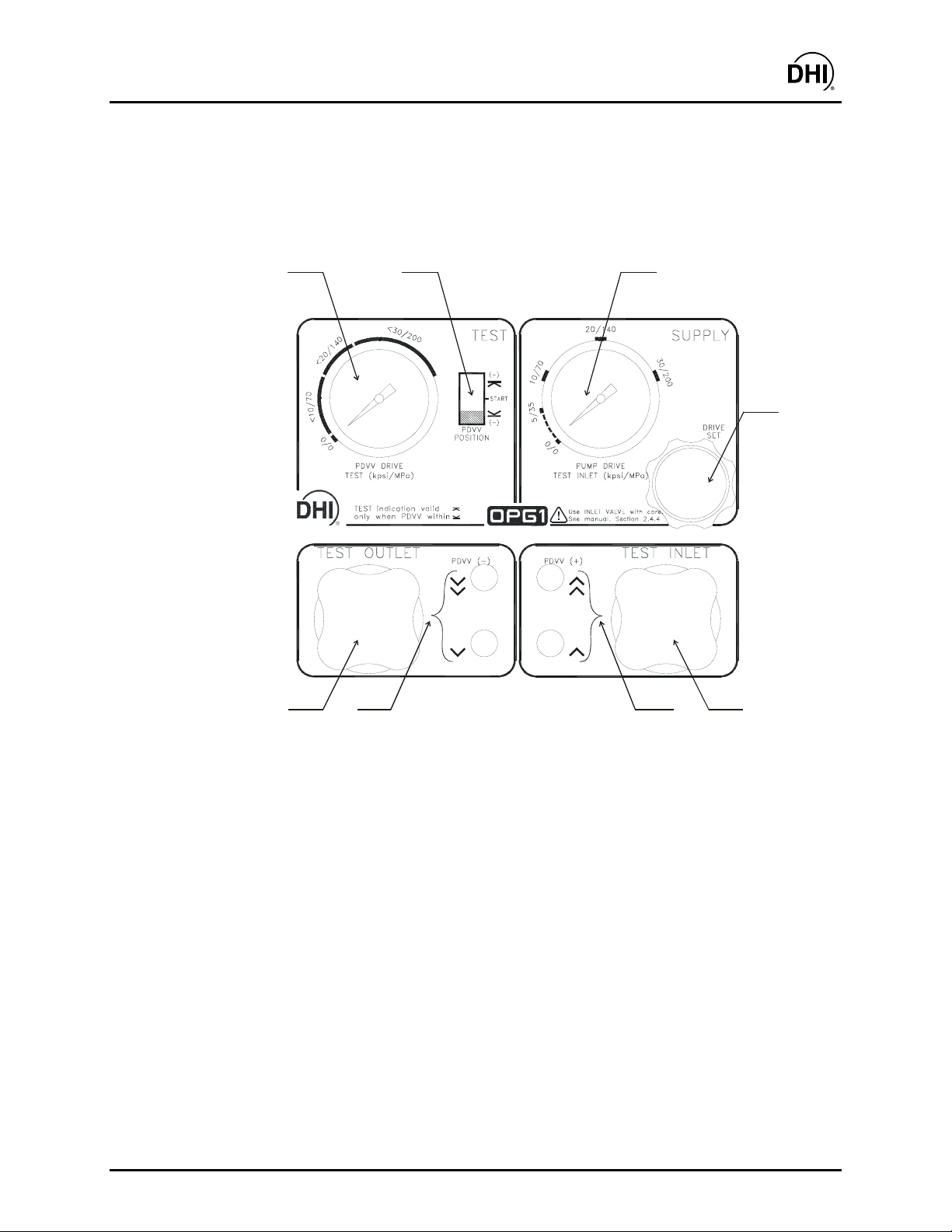
1.3.1 FRONT PANEL
The front panel provides all of the controls and indications needed to set and adjust pressure.
1
2
3
4
8
7
1. PDVV Drive Air/Test Oil Pressure Gauge
2. PDVV Piston Position Indicator
3. Pump Drive Air/Inlet Oil Pressure Gauge
4. Pump Drive Air Set Regulator
5. Test Inlet Valve Knob
6. PDVV Increase Fast and Slow Buttons
7. PDVV Decrease Fast and Slow Buttons
8. Test Outlet Valve Knob
6
5
Figure 1. Front Panel
Page 3 ©2000 DH Instruments, Inc.
Page 10
OPG1™ Operation and Maintenance Manual
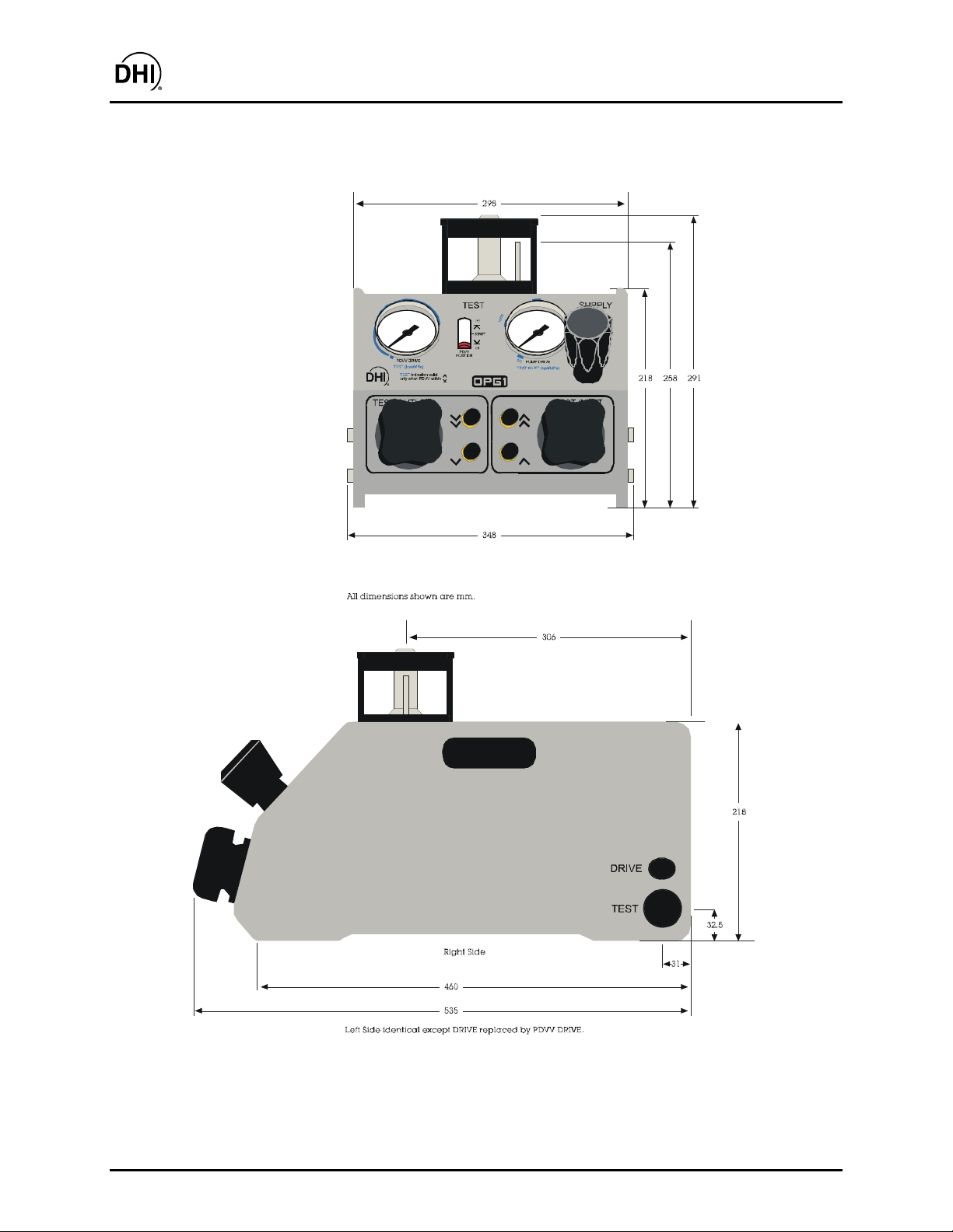
1.3.2 OVERALL DIMENSIONS
Figure 2. Front and Side Views with Dimensions
©2000 DH Instruments, Inc. Page 4
Page 11
OPG1™ Operation and Maintenance Manual
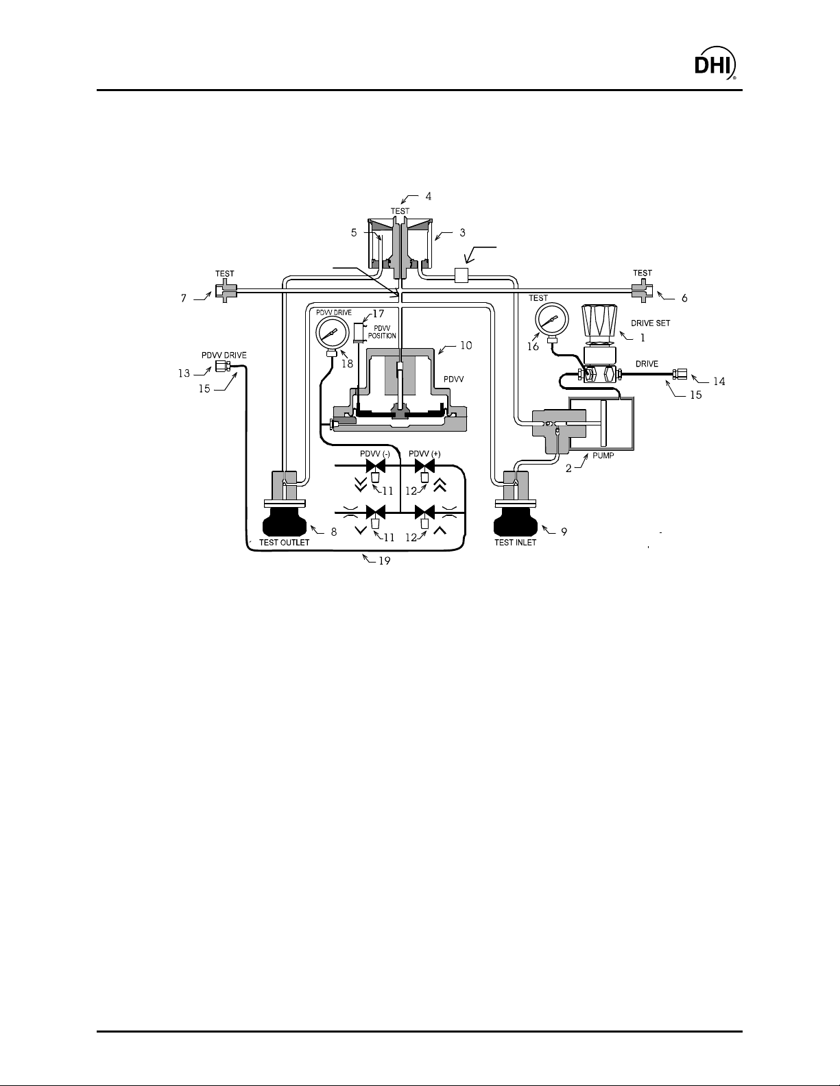
1.3.3 SYSTEM SCHEMATIC
21
20
1. Pump Drive Air Set Regulator 11. Fast and Slow PDVV Decrease Valves
2. Hydropneumatic Pump 12. Fast and Slow PDVV Increase Valves
3. Tank 13. PDVV DRIVE Air Connection
4. Top TEST Connection 14. Common DRIVE Air Connection
5. Oil Return Overflow Tube 15. DRIVE Air Filters
6. Right Side TEST Connection 16. PUMP DRIVE Pressure Gauge
7. Left Side TEST Connection 17. PDVV Plunger Position Indicator
8. Test Outlet Valve 18. PDVV DRIVE Pressure Gauge
9. Test Inlet Valve 19. PDVV DRIVE to PDVV Connection
10. Pneumatically Drive Variable Volume
(PDVV)
20. Oil Filter
Figure 3. System Schematic
Page 5 ©2000 DH Instruments, Inc.
Page 12

OPG1™ Operation and Maintenance Manual
N
N
OOTTEES
S
©2000 DH Instruments, Inc. Page 6
Page 13
OPG1™ Operation and Maintenance Manual
2. INSTALLATION
2.1 UNPACKING AND INSPECTION
2.1.1 REMOVING FROM PACKAGING
OPG1-30000-AF is delivered, along with its standard accessories in a corrugated container
with corrugated and polyurethane inserts to hold it in place.
Remove the OPG1 and its accessories from the shipping container and remove each
element from its protective plastic bag.
Retain the packaging in case of future OPG1 shipments.
2.1.2 INSPECTING CONTENTS
Check that all items are present and have NO visible damage. Verify the items received
against the parts list in Table 1.
Table 1. OPG1-30000-AF Parts List
DESCRIPTION PART NO.
OPG1-30000-AF Instrument 401602
Operation and Maintenance Manual 550114
Accessories: 401580
Mat, Top Surface Protection 122998
Sebacate (synthetic oil), 1 qt. 400503
Syringe, 10 cc 102817
O-ring, Brown Viton, 2-104 102758
Interconnections Kit: 401603
1 ea. Nipple, 2.75 in., DH500 100207
1 ea. Nipple, 6 in., DH500 100208
1 ea. Nipple, 24 in., DH500 100270
1 ea. Elbow, 24 in., DH500 123136
1 ea. Adaptor, DH500 F x 1/4 in. NPT M 102889
1 ea. Adaptor, DH500 F x 1/4 in. NPT F 102820
1 ea. Adaptor, DH500 F x 37 degree (AN4) Mi 102888
2 ea. Gland, DH500 100271
5 ea. Collar, DH500 100201
Page 7 ©2000 DH Instruments, Inc.
Page 14
OPG1™ Operation and Maintenance Manual
2.2 SITE REQUIREMENTS
The OPG1-30000-AF is typically delivered as part of an HGC-30000-AF hydraulic gauge calibrator
that includes an RPM3/HPMS-A30000/A6000-AF that has its own Operation and
Maintenance Manual.
When selecting and preparing a site to set up the OPG1-30000-AF and HGC-30000-AF system, the
following should be considered:
• Bench Stability: The OPG1 weighs about 27 kg (60 lb). The RPM3/HPMS-A30000/A6000-AF
weighs about 10 kg (22 lbs). Consider the combined weight and that of other components,
including possible items to be tested, when selecting a bench.
• Footprint: The HGC-30000-AF system requires a minimum bench space approximately 84 cm
(33 in.) wide and 60 cm (24 in.) deep.
• Location of Other Components: Plan the space required and a convenient layout for the
complete system in which OPG1 is the pressure generation/control component.
If the OPG1 is to be used with an RPM3/HPMS, the OPG1 accessories include the hardware
necessary for setting up in a standard configuration (see Sections 2.1.2, 2.3.1.3). These allow
the RPM3/HPMS to be placed to the right or the left of the OPG1, as desired.
The interconnecting tubing and fittings provided with the OPG1 accessories can also be used to
connect to other systems. If interconnections other than the OPG1 accessories are used, select
tubing and fittings rated to handle the maximum pressures that will be generated. OPG1
hydraulic fittings are all DH500 (equivalent to AE F250C, HIP HF4, etc.). The female DH500
fittings are delivered with gland nuts and plugs installed. Collars are included in the accessory
kit.
If you do not plan to use OPG1’s top TEST port, consider where a device or system under test
(DUT) will be connected.
• Pressure Supply: Plan the pneumatic power to OPG1. This requires two separate sources:
a) 850 kPa (120 psi) from an N2 or Air bottle connected to the rear left of the OPG1; b) 620 kPa
(90 psi) non-lubricated compressed air connected to the rear right of the OPG1 (see
Section 2.3.1.2). The connections are 1/4 in. NPT female.
• System Interconnections: Plan the interconnections between OPG1 and other components in
the system. Minimizing the volume and maximizing the mass of all interconnecting elements will
reduce pressure generation and stabilization time. An extra nipple is provided in the OPG1
interconnection accessories for possible connection to an existing oil/air separator (see
Section 2.3.1.3).
ALWAYS use external tubing and fittings rated for pressures equal to or greater than the
maximum pressure OPG1 will be used to generate.
©2000 DH Instruments, Inc. Page 8
Page 15

OPG1™ Operation and Maintenance Manual
2.3 INITIAL SETUP
2.3.1 PREPARING FOR OPERATION
Before setting up the OPG1, see Section 2.2 for general information on site requirements.
To prepare an OPG1 for check out and operation:
Set up the OPG1 (see Section 2.3.1.1).
Connect pneumatic power (see Section 2.3.1.2).
Make the system hydraulic pressure interconnections (see Section 2.3.1.3).
2.3.1.1 SET UP THE OPG1-30000-AF
To set up the OPG1, proceed as follows:
Place the OPG1 platform on the site table in the proper orientation with the front
panel controls conveniently accessible.
Fill tank with oil if necessary. Back off the tank cover until a gap for oil passage
can be seen between the DUT connection shaft and the cover. Pour in oil to just
under the overflow tube (see Section 4.2).
Leave tank cover open to allow oil to drain from the DUT connection and air to
escape when venting oil back to tank.
Install the mat delivered with accessories on top front of OPG1 around oil tank.
2.3.1.2 CONNECT PNEUMATIC POWER (DRIVE AIR)
OPG1 requires pneumatic power to drive two different components:
the hydropneumatic pump and the pneumatically driven variable volume (PDVV)
(see Section 3.1, Figure 6).
The drive air supply to the two components requires two independent connections
(see Section 3.1, Figure 6). The requirements for the two different components are
summarized in Table 2.
Page 9 ©2000 DH Instruments, Inc.
Page 16

OPG1™ Operation and Maintenance Manual
Make the two drive air connections as follows (but do not supply the air before
reading Section 2.4.3.2):
“DRIVE” connection (right side, rear): Connect a regulated air supply meeting
the requirements of Table 2 to the 1/4 in. NPT F “DRIVE” connection. This is
usually a shop air supply.
The maximum output pressure of the hydropneumatic pump is the drive air
pressure x 400. To avoid accidentally generating greater pressure than desired,
do not supply more pressure than necessary to the “DRIVE” connection.
“PDVV DRIVE” connection (left side, read): Connect a regulated air supply
meeting the requirements of Table 2 to the 1/4 in. NPT F “PDVV
DRIVE” connection. This is usually supplied from an N2 or Air “K” bottle.
The OPG1 “PDVV DRIVE” connection must be supplied with NON-LUBRICATED
drive air. The internal components are permanently lubricated. The oil in
lubricated air can contaminate the small diameter tubing inside OPG1 and lead
to erratic behavior requiring difficult and costly cleaning. Install a filter/dryer on
the drive air line if necessary.
CONNECTION
DRIVE
(right side,
rear)
PDVV DRIVE
(left side, rear)
FITTING
1/4 in.
NPT F
1/4 in.
NPT F
Table 2. Pneumatic Power (Drive Air) Requirements
INTERNAL
COMPONENT
SUPPLIED
Hydropneumatic
Pump
PDVV For 70 MPa (10 000 psi)
DRIVE AIR PRESSURE
620 kPa (90 psig) 50 slm
oil pressure:
550 kPa (80 psi)
For 140 Mpa (20 000 psi)
oil pressure:
700 kPa (100 psi)
For 200 Mpa (30 000 psi)
oil pressure:
850 kPa (120 psi)
NEEDED
MINIMUM
FLOW
(1.8 scfm)
*This is fairly
high flow.
200 sccm
(< 0.01 scfm)
*This is very low
flow.
LUBRICATED
No No
No
(must be dry)
CLEANLINESS
CRITICAL
Yes
©2000 DH Instruments, Inc. Page 10
Page 17

OPG1™ Operation and Maintenance Manual
6
3
2
2.3.1.3 MAKE HYDRAULIC PRESSURE INTERCONNECTIONS
CONNECTING TO THE RPM3/HPMS-A30000/A6000-AF
OPG1-30000-AF is delivered with a fittings accessory kit (see Section 2.1.2, Table 1).
This kit includes the high pressure hardware necessary to connect OPG1-30000-AF
to the RPM3/HPMS-A30000/A6000-AF. See Figure 4 for the recommended layout
and to identify the parts used from the interconnection kit. Figure 4 shows the
RPM3/HPMS installed to the right of the OPG1. It may be installed on either side
using either one of OPG1’s rear side test connections.
1
4
5
7
1. Optional connection to an existing oil/air interface or other device
(use 24 in. DH500 nipple P/N 100270)
2. OPG1-30000-AF
3. OPG1 TEST connection (DH500)
4. OPG1 to RPM3/HPMS connection (use 24 in. DH500 elbow P/N 123136)
5. RPM3/HPMS TEST connection (DH500)
6. RPM3/HPMS-A30000/A6000-AF
7. OPG1 connection for device under test
Figure 4. Connecting OPG1-30000-AF to an RPM3/HPMS
Page 11 ©2000 DH Instruments, Inc.
Page 18

OPG1™ Operation and Maintenance Manual
Always use external tubings and fittings rated for pressure equal to or greater than
the maximum pressure the OPG1 will be used to generate.
When planning system interconnections, consider that the time required to generate
and stabilize a pressure is a direct function of the test volume and the mechanical
stability of the test tubing and vessels. Always minimize volume to the extent
possible and use thick walled, high pressure tubing and vessels.
When planning a DUT or other fitting make and break point external to OPG1, consider
that if the point is lower than the OPG1 oil tank, oil will run out of the tank through
the open point when OPG1’s OUTLET valve is open.
The fluid head reference level of OPG1 when vented (OUTLET valve open), is the top of
the tank’s oil return overflow tube (see Section 3.2.6).
2.3.1.4 CONNECTING TO A DEVICE UNDER TEST
In an HGC-30000-AF system, the device under test (DUT) is intended to be
connected on the top of the OPG1 at the center of the oil tank (see Figures 6
and 10).
The top TEST connection is a DH500 F (DH500 is a gland and collar type fitting for
1/4 in. (6.35 mm) coned and left hand threaded tube. DH500 is equivalent to
AE F250C, HIP HF4, etc.
The OPG1-30000-AF fittings accessory kit includes adaptors to convert the DH500 F
TEST connection to other commonly used fittings. The adaptors are made by
combining a DH500 F adaptor with a 2.75 in. or 6 in. DH500 nipple. The nipple/adaptor
assembly is then installed on the DUT. Finally, the nipple/adaptor/DUT assembly is
installed on the OPG1’s DH500 F test connection. Note that the gland nut on the
adaptor/nipple assembly can be tightened into the DH500 F connection without rotating
the nipple or DUT. Adaptors available are:
• 1/4 in. NPT F
• 1/4 in. NPT M
• 37 degree flare M (AN4 M)
The test connection is a DH500.
©2000 DH Instruments, Inc. Page 12
Page 19

OPG1™ Operation and Maintenance Manual
The DH500 test connection can be converted to 1/8 in. NPT M or 1/4 in. NPT M
using the 2.75 in. (7 mm) tube and DH500 F x 1/8 in. NPT M or DH500 F x 1/4 in.
NPT M adaptor supplied in the OPG1 accessories. Install the tube into the adaptor.
Any device connected to the OPG1 and/or HGC-30000-AF system should be purged
of air to the extent possible prior to being connected to the system (see
Section 3.2.5).
OPG1 covers a very wide range of pressures all the way up to 200 MPa (30 000 psi).
It is the user’s responsibility to assure that fittings and devices connected to OPG1
are rated for the pressures at which they will be used.
If the DUT connection is lower than the OPG1 oil tank, when the OUTLET valve is open
and the DUT connection is open, oil will run out of the tank through the
DUT connection.
2.4 POWER UP AND VERIFICATION
2.4.1 APPLY PNEUMATIC POWER (DRIVE AIR)
Proceed as follows (numerical references refer to Section 3.2, Figure 7):
Fully back off the DRIVE SET regulator (4).
Close the TEST INLET valve (5).
Open the TEST OUTLET valve (8).
Connect the drive air supplies to the DRIVE and PDVV DRIVE ports, if you haven’t
already done so (see Section 2.3.1.2).
Adjust the external drive air regulator(s) to apply the appropriate level of pressure to the
DRIVE and PDVV DRIVE ports (see Section 2.3.1.2, Table 2).
Page 13 ©2000 DH Instruments, Inc.
Page 20

OPG1™ Operation and Maintenance Manual
2.4.2 ADJUST HYDROPNEUMATIC PUMP DRIVE AIR PRESSURE
This section assumes that the OPG1-30000-AF system has already been set up, including
pressure interconnection (see Section 2.3).
OGP1 hydraulic output pressure is directly proportional to pump DRIVE pressure. When the
OPG1 INLET valve is opened, the full pump pressure may be applied to the test system
very rapidly. ALWAYS adjust the pump pneumatic drive pressure low enough so that the
maximum pump output does not exceed the maximum pressure rating of the devices to which
OPG1 is connected.
Turn the DRIVE SET Regulator CW and observe the PUMP DRIVE Gauge to set the drive
air pressure to the desired level (the BLUE indication on outside of gauge gives the
approximate maximum oil pressure that will be generated).
2.4.3 CHECK PROPER OPERATION OF HYDROPNEUMATIC PUMP AND LEAK CHECK
Checking the proper operation of the hydropneumatic pump and leak checking has two
steps. The first step is purging air from the pump hydraulic circuit. The second step is
generating high pressures.
2.4.3.1 STEP ONE: PURGING AIR FROM THE HYDRAULIC PUMP CIRCUIT
Proceed as follows (numerical references refer to Section 3.1, Figure 6):
Verify that there is oil in the tank and verify that all test connections are plugged
or dead ended.
Open the OUTLET valve (8) fully.
Open the INLET valve (9) fully.
If drive pressure has been properly connected and set (see Section 2.4.2), pump
should begin cycling.
©2000 DH Instruments, Inc. Page 14
Page 21

OPG1™ Operation and Maintenance Manual
Observe tank oil return overflow tube (5). Continue allowing pump to cycle until
bubble free oil flows regularly from the tube. If no oil appears, or bubbles
continue to appear, a cavitated pump priming procedure must be used
(see Section 4.4).
If hydropneumatic pump is filled with air (cavitated), closing inlet valve will not
stop pump from operating. To stop pump, turn AIR DRIVE regulator (1) fully CCW
to stop air flow. See Section 4.4 for information on priming the pump if it
is cavitated.
After a successful purge, close the INLET valve (8), then the OUTLET valve (9)
and proceed to Step o (see Section 2.4.3.2) of hydropneumatic pump
operation checkout.
2.4.3.2 STEP TWO: GENERATING A PRESSURE
Before applying pressure to the OPG1 and/or the system connected to it, be sure
that all pressure vessels and connections are rated for the pressure levels that will
be applied and that all connections have been properly tightened.
OGP1 hydraulic output pressure is directly proportional to pump DRIVE pressure.
When the OPG1 INLET valve is opened, the full pump pressure may be applied to the
test system very rapidly. ALWAYS adjust pump drive air pressure low enough so that
the maximum pump output does not exceed the maximum pressure rating of the
devices to which OPG1 is connected (see Sections 2.4.2 and 3.2.1).
Proceed as follows (numerical references refer to Section 3.1, Figure 6):
Verify that there is oil in the tank.
Connect a high pressure indicating device to one of the OPG1 TEST ports (4, 6, 7).
Plug all other TEST ports (4, 6, 7).
There are three TEST ports on OPG1: One on each lower, rear side and one on the
top in the middle of the tank.
Fully close the OUTLET valve (8).
Slowly open INLET valve (9).
Page 15 ©2000 DH Instruments, Inc.
Page 22

OPG1™ Operation and Maintenance Manual
The pump should begin to cycle and the pressure indicated on the high pressure
device should increase. If the pump does not cycle, the drive pressure is set too
low or the pump is not operating correctly. If the pump cycles but the pressure
does not increase:
• The pump is not properly primed (see Section 2.4.3.1).
• There is a leak in the system to which the OPG1 is connected or in the
OPG1 itself.
• Air flow to the pump is too low.
• The pump is not operating properly.
Keep INLET valve (9) open until the desired oil pressure is set.
Fully close INLET valve (9).
Leak Check: The pressure indicated by the high pressure device connected to
the TEST port should stabilize and hold. If it does not, there is a leak in the
system to which OPG1 is connected or in OPG1 itself.
The time required for pressure to stabilize after the pressure has been changed
is directly proportional to the volume connected to OPG1 and the mechanical
stability of the volume's connections and vessels. To reduce stabilization time,
go beyond the pressure set point and return. Be sure the pressure has had time
to stabilize before concluding there is a leak in the system.
When leak checking is complete, slowly open the OUTLET valve (8) to remove
pressure and vent to atmosphere.
2.4.4 PRECAUTIONS TO TAKE BEFORE GENERATING PRESSURE/SAFETY CONSIDERATIONS
Before using the OPG1 to generate and adjust pressure, consider the following:
• Check that all connections, vessels and DUTs connected to OPG1 are rated for the
pressure to be generated and that all fittings are properly tightened.
• If the OPG1 is being used with an RPM3/HPMS, be sure that the HPMS valve is set to
shut off the low RPT of the RPM3 if pressure greater than 400 MPa (6 000 psi) will
be generated.
©2000 DH Instruments, Inc. Page 16
Page 23

OPG1™ Operation and Maintenance Manual
• Opening the INLET valve opens the test system to the output of the
hydropneumatic pump. As long as the INLET valve is open, the pump will cycle until
it stalls. To avoid accidental overpressure of the items to which OPG1 is connected,
always adjust the DRIVE SET regulator so that the hydropneumatic pump output will be
lower than the maximum desired pressure BEFORE opening the INLET valve
(see Sections 2.4.2 and 3.2.1).
Always adjust the DRIVE SET regulator so that the hydropneumatic pump output is not
higher than the maximum desired pressure BEFORE opening the INLET valve. Failure to
adjust the DRIVE SET regulator increases the chances of accidental overpressure of the
system connected to OGP1.
• When using INLET valve, pressure rate of rise may increase very rapidly after system
is primed. Exercise extra caution when setting the first pressure coming off zero.
When test is < 400 MPa (6 000 psi), consider using INLET valve to prime only (only until
pressure starts rising), then use PDVV for all pressure control.
• The
and push button valves can increase pressure very quickly. Observe pressure
evolution carefully when operating these valves (see Section 3.2.3).
• Check oil tank level before operating and regularly during operation. Operating with an
empty oil tank will cause the hydropneumatic pump to draw air and require priming it (see
Section 4.4).
• Put the PDVV in the START position when starting a calibration or test sequence (see
Section 3.2.3).
• Systems and DUTs connected to OPG1 should be purged of air before they are
pressurized (see Section 3.2.5).
• If there is an open point in the system to which OPG1 is connected that is lower than the
OPG1 tank, oil will run out of the OPG1 tank through this point when the OUTLET valve
is open. Close the OUTLET valve when a point lower than the tank is open.
• The fluid head reference level of OPG1 when the OUTLET valve is open is the top of the
tank return overflow tube. Consider the difference between this reference level and the
reference measuring device reference level to avoid zero gauge points that are
inconsistent with other pressure points (see Section 3.2.6).
Page 17 ©2000 DH Instruments, Inc.
Page 24

OPG1™ Operation and Maintenance Manual
2.5 SHORT TERM SHUT-DOWN
When leaving OPG1 at rest but still set up for operation:
Fully close the INLET valve.
Release hydraulic pressure by fully opening the OUTLET valve.
Plug any open point in the hydraulic test system connected to OPG1 that is lower than the OPG1
tank or the oil will run out of the tank through the open point.
Release pump drive pressure by fully backing off the DRIVE SET regulator.
2.6 LONG TERM STORAGE AND SHIPPING
To prepare OPG1 for long term storage or shipping:
Release hydraulic pressure by fully opening the OUTLET valve.
Release pump drive pressure by fully backing off DRIVE SET regulator.
Release pneumatic drive pressure and disconnect the DRIVE and PDVV DRIVE pressure
connection(s). Cap both ports with plastic caps if available.
Close the OUTLET valve and INLET valve.
Disconnect all hydraulic pressure connections and plug the connections using DH500 plugs held
by gland nuts (DH500 plugs were delivered with OPG1-30000-AF). There are three hydraulic
connections: one on either side labeled TEST and one on top at the center of the tank cover.
Screw the tank cover firmly shut. Oil may be left in the tank.
When shipping OPG1, use the original shipping materials, if possible. When using alternate
materials (If the original shipping materials are not available) take care to assure that: a) the
front panel controls and indicators are protected; b) the top mounted oil reservoir is not
subjected to shock or load; c) the tubing and components exposed through OPG1’s open bottom
are protected. OPG1 must carry its weight on its four feet - NOT on its internal components.
©2000 DH Instruments, Inc. Page 18
Page 25

OPG1™ Operation and Maintenance Manual
3. GENERAL OPERATION
3.1 OPERATING PRINCIPLE
Numerical references in this section refer to Section 3.1, Figure 5.
OPG1-30000-AF is a self-contained system designed to generate and adjust pressure from
atmosphere (zero gauge) to 200 MPa (30 000 psi) in and HGC-30000-AF Hydraulic Gauge
Calibrator System. OPG1 combines the capability to fill the system with oil and execute large
pressure changes very rapidly with very fine pressure adjustment around a point.
OPG1 uses two different techniques to generate and adjust pressure.
The first means of generating and adjusting pressure is the hydropneumatic pump (2) combined
with the oil tank (3), DRIVE SET regulator (1), INLET valve (9) and OUTLET valve (8).
This combination is used for filling the system under test, large pressure changes and rough
pressure control. The valves are Belleville spring loaded, highly progressive, half-turn needle
valves. The pump is a pneumatically powered, gate valve controlled, piston pump similar to a
double-acting pneumatic cylinder. There is a ratio of 400:1 between the pneumatic piston and
hydraulic plunger. The pump will operate continuously until the pneumatic drive pressure on the
pneumatic piston is in equilibrium with the oil pressure on the oil plunger. For example, if the
pneumatic drive pressure is 500 kPa (75 psi), the pump will cycle until the oil pressure reaches
200 MPa (30 000 psi). The pump draws oil from the oil tank on top of OPG1. The DRIVE SET
regulator (1) is used to set the pneumatic drive pressure to the pump and thus the oil output
pressure. The pump oil output is connected to the INLET valve (9). Opening the INLET valve
connects the pump output to the test system causing the pump (2) to cycle, drawing oil from the tank
as needed and pressurizing the system. Opening the OUTLET valve (8) returns oil to the tank (3),
depressurizing the system.
The second means of generating and adjusting pressure is the Pneumatically Controlled Variable
Volume (PDVV) (10) combined with the PDVV (+) valves (12) and PDVV (-) valves (11).
This combination is used for smaller pressure changes and fine pressure control. The PDVV
is a pneumatically actuated variable volume. A piston or plunger in a cylinder is exposed to the
oil pressure. The other end of the plunger is connected to a dome loaded pneumatic actuator.
Changing the pneumatic pressure on the dome loaded actuator causes the plunger to move,
increasing or decreasing oil pressure. A spring returns the plunger to its minimum stroke position
when there is no pressure on it. A mechanical system tracks movement of the plunger and an
indicator (17) displays the plunger position on the front panel. The PDVV (+) valves (12) and PDVV (-)
valves (11) are momentary, poppet valves that open when pressed. The (+) valves (12) admit drive
air pressure to the PDVV actuator causing the PDVV piston to move forward compressing the oil and
increasing the pressure. The (-) valves (11) have the opposite effect causing pressure to decrease.
Page 19 ©2000 DH Instruments, Inc.
Page 26

OPG1™ Operation and Maintenance Manual
20
21
1. Pump Drive Air Set Regulator 11. Fast and Slow PDVV Decrease Valves
2. Hydropneumatic Pump 12. Fast and Slow PDVV Increase Valves
3. Tank 13. PDVV DRIVE Air Connection
4. Top TEST Connection 14. Common DRIVE Air Connection
5. Oil Return Overflow Tube 15. DRIVE Air Filters
6. Right Side TEST Connection 16. PUMP DRIVE Pressure Gauge
7. Left Side TEST Connection 17. PDVV Plunger Position Indicator
8. Test Outlet Valve 18. PDVV DRIVE Pressure Gauge
9. Test Inlet Valve 19. PDVV DRIVE to PDVV Connection
10. Pneumatically Drive Variable
Volume (PDVV)
20. Oil Filter
Figure 5. System Schematic
©2000 DH Instruments, Inc. Page 20
Page 27

OPG1™ Operation and Maintenance Manual
3.2 OPERATIONAL FUNCTIONS
All OPG1 operational functions are accessed from the instrument front panel. Sections 3.2.1 to 3.2.6
detail the various functions.
1
2
3
1. PDVV Drive Air/Test Oil Pressure Gauge
4
2. PDVV Piston Position Indicator
3. Pump Drive Air/Inlet Oil Pressure Gauge
4. Pump Drive Air Set Regulator
5. Test Inlet Valve Knob
6. PDVV Increase Fast and Slow Buttons
7. PDVV Decrease Fast and Slow Buttons
8. Test Outlet Valve Knob
8
7
6
5
Figure 6. Front Panel
3.2.1 SETTING INLET PRESSURE, DRIVE SET REGULATOR ADJUSTMENT
Numerical references in this section refer to Section 3.2, Figure 6.
The DRIVE SET regulator (4) is a self venting regulator that sets the pneumatic drive
pressure to the hydropneumatic pump. This determines the oil pressure that the pump will
generate before stalling and that is available on demand when the INLET valve (5)
is opened.
The PUMP DRIVE gauge (3) indicates the pump drive pressure on its inner dial and the
corresponding pump output oil pressure on its outer dial (BLUE numbers). Use the outer
BLUE indication to predict the maximum pressure that will be generated when the inlet valve
is opened.
Page 21 ©2000 DH Instruments, Inc.
Page 28

OPG1™ Operation and Maintenance Manual
With the INLET valve (5) closed, use the DRIVE SET regulator (4) and the PUMP DRIVE
gauge (3) indication to set the desired maximum pump output pressure. This is generally
done at the beginning of a test or calibration based on the maximum pressure of
the calibration. It is good practice to set the pump output pressure below the maximum
pressure desired to avoid accidental overpressure. The PDVV can then be used for the final
pressure adjustment at the maximum pressure (see Section 3.2.3).
The DRIVE SET regulator sets the oil pressure output of the hydropneumatic pump. When the
INLET valve is opened, this pressure can be generated very rapidly in the system connected
to OPG1. Use caution in setting the pump drive pressure and always check the setting and
adjust if necessary before using the INLET valve (see Sections 2.4.2 and 3.2.1).
3.2.2 ROUGH PRESSURE GENERATION/CONTROL, INLET AND OUTLET VALVE OPERATION
Numerical references in this section refer to Section 3.2, Figure 6.
The INLET valve (5) and OUTLET valve (8) are high pressure needle valves.
Their operation is highly progressive over a half-turn with mechanical stops at each end so
they cannot be overtightened. The valve is turned CW to close and CCW to open. A WHITE
dot on the handle body indicates its current open/close position.
The INLET valve (5) controls the flow of oil from the hydropneumatic pump into the
test system. When the INLET valve is closed, the pump is shut off from the test system and
dead ended. When the INLET valve is open, the pump output is connected to the test
system and can fill and generate pressure into the system.
The OUTLET valve (8) controls the flow of oil from the test system back to the tank. When it
is closed, the test system is shut off from the tank. When the OUTLET valve is open, the
system returns oil to the tank and is opened to atmospheric pressure.
The INLET valve (5) and OUTLET valve (8) are used to execute large pressure changes in
the test system and for rough pressure control. The INLET valve is used to connect to the
pump to purge and prime the test system at the beginning of a test or calibration.
The OUTLET valve, when fully opened, is the means of opening the test to atmosphere and
setting zero pressure. The INLET valve and OUTLET valve are not generally used for
ON/OFF action but progressively to roughly set the desired pressure. Exercise caution when
operating the valves to not open them too quickly which may cause pressure in the system to
change much more rapidly than desired.
The INLET valve connects the output of the hydropneumatic pump to the test system.
When the INLET valve is opened, high pressure can be generated very rapidly in the system
connected to OPG1. Use caution in opening the INLET valve and always check the PUMP DRIVE
gauge before doing so (see Sections 2.4.2 and 3.2.1).
©2000 DH Instruments, Inc. Page 22
Page 29

OPG1™ Operation and Maintenance Manual
3.2.3 FINE PRESSURE ADJUSTMENT, PDVV (+) AND (-) VALVE OPERATION
Numerical references in this section refer to Section 3.2, Figure 6 except where
specified otherwise.
The PDVV (+) valves (6) and PDVV (-) valves (7) are push button, poppet valves that
control the supply and exhaust of drive air pressure to the PDVV actuator (see Section 3.1).
When the push button is pressed, the valve opens. When the push button is released the
valve closes.
The valves labeled
to back off and oil pressure to decrease. The valves labeled
and release gas from the PDVV actuator causing the PDVV plunger
and admit gas to the
PDVV actuator causing the PDVV plunger to move forward and oil pressure to increase. The
and valves are for high speed PDVV operation. The and valves are for slow speed
PDVV operation.
The PDVV (+) valves (6) and PDVV (-) valves (7) are used to make small pressure changes
and for fine pressure control. Brief momentary action on the
and valves is used to
bump or jog pressure in very small amounts around a pressure point.
The actual rate of pressure change caused by the PDVV (+) valves and PDVV (-) valves is
dependent on the test volume that is connected to OPG1. Increasing the test volume lowers
the rates and pressure step size. The maximum pressure that can be generated by the
PDVV (+) valves is dependent on the drive air supply (see Section 2.3.1.2, Table 2).
The position of the PDVV plunger is indicated by the PDVV POSITION indicator (2). The
RED index (Figure 7, Ref 4) on the indicator tracks the movement of the PDVV plunger.
Minimum and maximum end of stroke positions (Figure 7, Refs 3 and 1) as well as a
recommended start position (Figure 7, Ref 2) are indicated. The full stroke displacement of
the PDVV plunger from maximum to minimum end of stroke is 1 cc (0.06 in.).
START
PDVV
POSITION
1. PDVV Plunger Maximum End of Stroke
2. PDVV Plunger Recommended Start Position
3. PDVV Plunger Minimum End of Stroke
4. PDVV Plunger Current Position (red/white line)
Figure 7. PDDV Position Indicator
The current air drive pressure on the PDVV actuator and approximate corresponding oil test
pressure are indicated by the PDVV DRIVE gauge (1). The oil test pressure indication is
highly approximate and only valid when the PDVV plunger is NOT at an end of
stroke position.
Page 23 ©2000 DH Instruments, Inc.
Page 30

OPG1™ Operation and Maintenance Manual
For the PDVV (+) valves (6) and PDVV (-) valves (7) to have an effect, the PDVV plunger
must have stroke available. If the PDVV is at its end of stroke (Figure 7, Ref 1 or 3), the
plunger cannot move to change pressure. The recommended PDVV START position
(Figure 8, Ref 2) puts the plunger at the middle of its stroke so 50 % of PDVV displacement is
available in either direction. The PDVV plunger can be positioned without affecting oil
pressure using the
and valves when the OUTLET valve is open (oil pressure vented).
The plunger is returned to minimum end of stroke position by a spring. The PDVV plunger is
usually set to the desired position at the start of a calibration or test.
If the PDVV plunger reaches end of stroke during a calibration or test, used the INLET valve
and/or OUTLET valve to increase or decrease the pressure, as needed.
The PDVV (+) valves (6), generate pressure indefinitely when opened. Use caution not
to generate more pressure than desired when using these valves.
3.2.4 CONNECTING A DEVICE UNDER TEST (DUT)
See Section 2.3.1.4.
OPG1 covers a very wide range of pressures all the way up to 200 MPa (30 000 psi). It is the
user’s responsibility to assure that fittings and devices connected to OPG1 are rated for the
pressures at which they will be used.
If the DUT connection is lower than the OPG1 oil tank, when the OUTLET valve is open and the
DUT connection is open, oil will run out of the tank through the DUT connection.
3.2.5 PURGING AIR FROM THE DUT/SYSTEM UNDER TEST
Air is highly compressible. Oil is not. To the extent possible, air should be purged from the
system and devices that are connected to OPG1 prior to applying pressure to them.
Leaving air in the DUT reduces OPG1 efficiency, increases the time required to generate
pressures, increases the dangers associated with high pressure operation and makes it more
difficult to set a valid zero point.
The system and/or DUTs that are connected to OPG1 can be filled with oil prior to connecting
them or they can be purged using OPG1. To purge air using OPG1, open the system or DUT
at the highest point possible. Close the OPG1 OUTLET valve. Then carefully open the
INLET valve causing oil to be drawn from the tank and pumped into the system. Observe
the oil level at the purge point. Close the INLET valve when oil is present at the purge point.
While purging, watch the tank oil level carefully to be sure it is filled. Do not run the
hydropneumatic pump without oil in the reservoir.
©2000 DH Instruments, Inc. Page 24
Page 31

OPG1™ Operation and Maintenance Manual
3.2.6 MEASUREMENT REFERENCE LEVEL WHEN VENTED
Generally, the test or calibration system is opened to atmosphere (zero gauge pressure) by
opening the OPG1 OUTLET valve.
The fluid head reference level when the OUTLET valve is open is the top of the tank return
overflow tube. This point is 258 mm (10.15 in.) above the surface on which OPG1 is sitting
(see Figure 8).
Figure 8. Fluid Head Level When Vented, INLET Valve Open
When the OUTLET valve is closed, the fluid head reference level is at the device being used
as the measurement reference. Consider the possible difference in fluid head between the
two conditions or incorrect fluid head corrections will be applied and the zero point will be
inconsistent with other measurements.
See the RPM3/HPMS-A30000/A6000-AF Operation and Maintenance Manual for
recommendations on setting zero and handling fluid heads when using OPG1 in an
HGC-30000-AF system.
OPG1 is designed so that the top of the oil tank return overflow tube aligns with the
measurement reference level of a PG7302 oil operated piston gauge. This assures that, when
using a PG7302 piston gauge, the nominal reference level is the same at zero with the OPG1
vented and when pressures are defined by the piston gauge.
\
When the OPG1 OUTLET valve is open, the test system is connected to the OPG1 oil tank.
If there is an open point in the test system below the oil level in the oil tank, oil will run from
the tank and out of the open point in the test system.
Page 25 ©2000 DH Instruments, Inc.
Page 32

OPG1™ Operation and Maintenance Manual
3.3 TYPICAL OPERATING SEQUENCE FOR A COMPLETE CALIBRATION OR TEST
OPG1-A30000-AF is most often used to generate and adjust pressures to a reference measuring
device and a DUT when performing a test or calibration. In an HGC-30000-AF the reference
measuring device is an RPM3/HPMS-A30000/A6000-AF.
The typical operational sequence for a complete calibration or test when using the OPG1-A30000-AF
in an HGC-30000-AF system is as follows (numerical references refer to Section 3.2, Figure 6):
Connect the DUT to the OPG1 TEST port on the top of the OPG1 tank (see Section 2.3.1.4).
Position the PDVV plunger: Open the OUTLET valve (8). Use the PDVV (+) valves (6) and
PDVV (-) valves (7) and the PDVV POSITION indicator (2) to position the PDVV plunger at the
START position or at another desired position (for example near the minimum end of stroke if the
PDVV is to be used extensively for pressure generation).
p Set the pump drive pressure: Adjust the DRIVE SET regulator (4) and observe the pressure
on the PUMP DRIVE gauge (3). Set the pressure so that the pump oil pressure output will be
just under the maximum pressure to be reached in the test.
Take the starting zero reading on the DUT: With the OUTLET valve (8) open, the pressure in
the test system is zero gauge and the fluid head reference level is the top of the oil tank return
overflow tube. Loosen the TEST connection fitting if desired to be sure no back pressure is
applied to the DUT when checking the DUT zero point.
Initialize the test on the RPM3/HPMS-A30000/A6000-AF (see the RPM3/HPMS Operation
and Maintenance Manual): Press [ENTER] on the keypad of the RPM3 and initialize the test.
Set ascending test pressures: Carefully open the INLET valve (5) and control the oil input
from the pump to set the pressure in the test system just under the desired test point. Then use
the PDVV (+) valves (6) and PDVV (-) valves (7) to adjust the pressure to the pressure desired
as indicated by the DUT. Repeat this process for all of the ascending increments. If the
increments are small enough for the PDVV displacement to generate the pressure, only the
PDVV (+) valves may be needed to generate the next pressure. If the PDVV runs out of stroke,
use the INLET valve to generate pressure.
Set descending test pressures: Very carefully open the OUTLET valve (8) and control the oil
return to the tank to set the pressure in the test system just over the desired test point. Then use
the PDVV (+) valves (6) and PDVV (-) valves (7) to adjust the pressure to the exact test
pressure desired as indicated by the DUT. Repeat this process for all of the descending
increments. If the increments are small enough for the PDVV displacement to generate the
pressure, only the PDVV (-) valves
runs out of stroke, use the OUTLET valve to reduce pressure.
Vent the system and disconnect the DUT: Open the OUTLET valve (8) fully.
Disconnect the DUT. If the test port is lower than the oil level in the oil tank, be sure to close the
OUTLET valve so that oil does not run out of the tank through the test port.
may be needed to generate the next pressure. If the PDVV
©2000 DH Instruments, Inc. Page 26
Page 33

OPG1™ Operation and Maintenance Manual
4. MAINTENANCE
ADJUSTMENTS AND
CALIBRATION
4.1 OVERVIEW
OPG1 was designed for maintenance free operation. The hydropneumatic pump and PDVV are
permanently lubricated. No maintenance is required other than:
• Maintain oil level in tank: Replace lost oil to never allow the tank to empty which would cause
the pump to run without oil (see Section 4.2).
• Replace oil and purge hydraulic system when oil becomes dirty: Over time, contamination
from the system to which OPG1 is connected may cause the oil to become contaminated.
It should then be replaced and the OPG1 hydraulic system purged (see Section 4.3).
• Prime hydropneumatic pump if it becomes cavitated: If the hydropneumatic pump is run
without oil in the tank, it may fill with air and become cavitated. If this occurs, the pump will no
longer draw oil and generate pressure. To correct the situation, the pump must be primed (see
Section 4.4).
• Clean/replace filter elements on PDVV and hydropneumatic pump drive air filters:
The filters may become contaminated and restrict the free flow of drive air pressure. They should
then be cleaned or replaced (see Section 4.5).
Maintenance and repair services for OPG1 are offered by authorized DHI Authorized Service
Providers (see Section 6.1, Table 4).
Page 27 ©2000 DH Instruments, Inc.
Page 34

OPG1™ Operation and Maintenance Manual
OPG1 is a sophisticated pressure generation and adjusting instrument with advanced features
and functions. Before assuming that unexpected behavior is caused by a system defect or
breakdown, use this manual and other training facilities to become thoroughly familiar with
OPG1 operation. For rapid troubleshooting assistance in specific situations, see Section 5.
Standard, commercial OPG1s are covered by a limited 1 year warranty (see Section 6.1).
OPG1-30000-AFs delivered under F33660-99-C7003 are covered by a limited, 5 year
worldwide warranty. The warranty start and finished dates are marked on each unit.
Unauthorized service or repair during the warranty period is undertaken at the owner's risk and
may cause damage that is NOT covered under the product warranty and/or may void the
product warranty.
4.2 FILLING THE TANK
The oil level in the OPG1 tank should be maintained at all times. Opening the INLET valve and
operating the hydropneumatic pump when the tank is empty will cause the pump to draw air and lose
its prime.
To fill the oil tank, proceed as follows (numerical references refer to Figure 9):
Unscrew the tank cover/oil fill funnel (2) until a gap for oil passage can be seen between the
TEST port shaft (1) and the cover.
Using the tank cover as a funnel, pour oil into the tank to just under the top of the overflow
tube (3). DO NOT bring the oil level in the tank above the top of the overflow tube.
Leave the tank cover open to allow oil to drain from the cover into the tank when swapping DUTs
and to allow air to escape from the tank when venting oil back into the tank.
1. TEST Port
2. Tank Cover/Oil Fill Funnel (screws off)
3. Oil Return Overflow Tube (oil return)
4. Pump Draw (oil outlet)
Figure 9. Oil Tank
©2000 DH Instruments, Inc. Page 28
Page 35

OPG1™ Operation and Maintenance Manual
4.3 REPLACING OIL AND PURGING CONTAMINATED OIL
If OPG1 is used to generate and adjust pressure into test systems and DUTs that are not clean, the
oil returned to OPG1 will become contaminated.
Observe the oil in the OPG1 tank. If its color is significantly different from the color of clean oil or if
any particulate contamination can be observed, replace the oil in the oil tank and purge the OPG1
oil system.
To replace the oil in the oil tank proceed as follows:
Fully remove the oil tank cover by unscrewing it (rotating CCW) and removing it completely.
Remove the oil from the tank with a suction bulb or similar device.
Clean out the tank with paper towels or rags. Remove all particulates that may be present.
Refill the tank with fresh oil to just under the overflow tube.
To purge OPG1 of dirty oil proceed as follows:
Fill the oil tank with clean oil (see Section 4.2).
Open one of the side TEST ports and put a cup under the port.
Close the OUTLET valve. Open the INLET valve causing the pump to cycle and oil to be drawn
from the tank and expelled from the open TEST port. Observe the oil coming out of the test port
until it runs clean. TAKE CARE to not allow the oil level in the tank to run out or the pump will
draw air and lose its prime, requiring it to be primed (see Section 4.4). When the oil coming out
the TEST port is running clean, close the INLET valve.
Repeat from Step , if necessary, until the oil running out the TEST port runs clean and the oil in
the tank is clean.
Page 29 ©2000 DH Instruments, Inc.
Page 36

OPG1™ Operation and Maintenance Manual
4.4 PRIMING THE HYDROPNEUMATIC PUMP
If hydropneumatic pump is filled with air (cavitated), if will pump continuously when drive air is applied
without drawing oil from the tank or generating oil pressure. If you believe the pump may be
cavitated, first attempt to purge it following the procedure described in Section 2.4.3.1. If the pump
cannot be purged, use the priming by syringe injection procedure described in Section 4.4.1. If the
syringe injection procedure is not successful, consider using the internal priming procedure described
in Section 4.4.2.
4.4.1 PRIMING THE HYDROPNEUMATIC PUMP BY SYRINGE INJECTION
The hydropneumatic pump injection priming procedure is only required if the regular purge
procedure fails (see Section 2.4.3.1).
Numerical references in this section refer to Section 4.2, Figure 9.
To prime the pump with the syringe proceed as follows:
Back off the OPG1 DRIVE SET regulator to zero by turning it fully CCW.
Open INLET valve and OUTLET valve.
Remove oil tank cover (2).
Install 2-104 O-ring on tip of 10 cc syringe (both supplied in OPG1 accessory kit, see
Section 2.1.2).
Fill syringe with oil from the tank.
Insert the tip of the syringe into the tank pump draw port (4) and press so that the O-ring
seals against bottom of tank.
Increase pump drive air pressure by rotating DRIVE SET regulator CW until the pump
begins to cycle. When pump begins to cycle, press syringe plunger, injecting oil
into pump. Continue until oil returning through the tank oil return overflow tube (3) is free
of air bubbles. Note that in some cases, air free oil will return before trapped gas is
expelled from the pump.
©2000 DH Instruments, Inc. Page 30
Page 37

OPG1™ Operation and Maintenance Manual
4.4.2 INTERNAL PURGE OF HYDROPNEUMATIC PUMP
The hydropneumatic pump internal purge procedure is only required if the regular purge
procedure fails (see Section 2.4.3.1) and a syringe is not available to perform the injection
priming procedure (see Section 4.4.1).
To purge the hydropneumatic pump internally, proceed as follows (see Figure 10):
Figure 10. Hydropneumatic Pump
Verify that there is oil in the tank.
Back off DRIVE SET regulator to zero.
Position the OPG1 so that you can access the hydraulic output pressure connection (1)
of the hydropneumatic pump while keeping the OPG1 in its normal, horizontal
operating position. This is accomplished by placing either end on separate tables and
accessing the pump from beneath OPG1 or by slightly lifting the front of the OPG1.
1. Hydraulic Output Pressure Connection
Open the INLET valve fully.
Use a wrench to turn the hydraulic output pressure connection gland (1) 1/8 turn CCW.
This cracks the connection so that output oil from the pump can escape through the
safety weep hole.
Slightly adjust DRIVE SET regulator CW until the pump starts cycling.
Allow the pump to cycle until clear, bubble free oil flows regularly from the weep hole.
If this does not occur, the pump may require service. Contact your DHI Authorized
Service Provider (see Section 6.1).
Retighten the hydraulic output pressure connection (1) by turning the gland nut
approximately 1/8 turn CW.
Go to Section 2.4.3.1 and proceed with the normal purge procedure.
Page 31 ©2000 DH Instruments, Inc.
Page 38

OPG1™ Operation and Maintenance Manual
4.5 CLEANING/REPLACING DRIVE AIR FILTER ELEMENTS
There are filters on the OPG1 drive air inlet ports, one on the PDVV DRIVE port and the other on the
DRIVE port. If the drive air supplied is excessively dirty, the filters may become contaminated and
restrict air flow to the PDVV and/or hydropneumatic pump (see Section 3.1, Figure 6).
The drive air filters are filter bodies with scintered elements. To clean or replace the drive air filters,
the filter body must be removed from OPG1.
To remove and reinstall the drive air filters, proceed as follows:
Close the OPG1 tank cover fully and plug all hydraulic ports. Ensure that tank is filled to just
under oil return tube.
Place the OPG1 back down on the bench, so that the front panel is up with the open bottom
towards you.
Disconnect the filter connection fittings (2, 4) for the PDVV DRIVE filter (3) and (8, 10) for DRIVE
filter (9). Remove the filter (3) and/or (9).
To reinstall the filter, make the filter connections (2) and (4) or (8) and (10). Take care to insure
that the filter is oriented in the correct direction (determined by the arrow on the filter body).
The two filters are identical.
Connect recommended pressures (see Section 2.3.1.2, Table 2) to the PDVV DRIVE port and
DRIVE port. Check new connections for leaks using a liquid leak detector. Correct leaks,
if present.
The filters may be replaced completely, cleaned by back flushing or disassembled and the filter
element cleaned or replaced.
To disassemble the filter body, open the body by unscrewing the filter body cap CCW. Once the filter
body cap is removed, the scintered filter element can be removed.
1. PDVV DRIVE Port 5. Cap 9. DRIVE Filter
2. PDVV DRIVE Filter Upstream 6. PFA PDVV Supply Tube 10. DRIVE Filter Upstream
Connection 7. DRIVE Tee PDVV Connection Connection
3. PDVV DRIVE Filter 8. DRIVE Filter Downstream 11. DRIVE Port
4. PDVV DRIVE Filter Downstream Connection
Connection
Figure 11. Drive Air Filters
©2000 DH Instruments, Inc. Page 32
Page 39

OPG1™ Operation and Maintenance Manual
5. TROUBLESHOOTING
PG1 is a sophisticated pressuring generating and adjusting instrument with advanced features
and functions. Before assuming that unexpected behavior is caused by a system defect or
breakdown, the operator should use this manual and other training facilities to become thoroughly
familiar with OPG1 operation. This troubleshooting guide is intended as an aid in identifying the
cause of unexpected OPG1 behavior and determining whether the behavior is due to normal
operation or an internal or external problem.
Identify the symptom or unexpected behavior you are observing from the Symptoms listed in
Table 3. A Probable Cause is provided and a Solution is proposed including references to manual
sections that provide information that may be of assistance.
Table 3. OPG1 Troubleshooting Checklist
SYMPTOM PROBABLE CAUSE SOLUTION
Test pressure continuously
increases even with all valves
closed.
Test pressure continuously
decreases even with all valves
closed.
Test pressure takes too long to
stabilize or will never stabilize.
Leak in INLET valve or leak in
PDVV (+) valve(s).
Leak in OUTLET valve, leak in
PDVV (-) valve(s) or
pneumatic circuit, leak in
OPG1 hydraulic circuit or leak
in test volume to which OPG1
is connected.
You are observing normal
evolution of pressure in an
uncontrolled static volume,
excess gas in hydraulic circuit.
Isolate leak to INLET valve or PDVV
(+) valve(s) by checking whether
pressure continues to increase when
PDVV (-) valves are opened or PDVV
is at end of stoke. Replace or repair
valve(s) if qualified to do so. Contact
DHI Authorized Service Provider.
(6.1)
Identify and correct leak in test volume
if present. Isolate leak to OUTLET
valve or PDVV (-) valve(s) by
checking if pressure continues to
decrease when PDVV is in minimum
end of stroke position. Replace or
repair valve(s) if qualified to do so.
Contact DHI Authorized Service
Provider. (6.1)
Reduce test volume. Increase
stability of test tubings and vessels.
Wait longer for stability. Overshoot
test point and return to reduce
stabilization time. Reduce reference
reading resolution to appropriate level.
Page 33 ©2000 DH Instruments, Inc.
Page 40

OPG1™ Operation and Maintenance Manual
Table 3. OPG1 Troubleshooting Checklist (Continued)
SYMPTOM PROBABLE CAUSE SOLUTION
PDVV will not increase pressure. PDVV is at maximum end of
stroke position, PDVV supply
pressure is not high enough, or
PDVV supply plugged.
PDVV will not decrease
pressure.
Opening INLET valve does not
increase pressure.
Pump cycles continuously
without generating pressure.
Pump cycles continuously
without generating pressure.
Pump cycles continuously
without generating pressure.
Pump cycles excessively before
beginning to generate pressure.
PDVV is at minimum end of
stroke position.
Pump drive pressure too low. Adjust pump drive pressure, increase
The pump has lost its prime,
oil tank empty.
OUTLET valve is open. Close OUTLET valve. (3.2.2)
There is a large leak in the test
system to which OPG1 is
connected.
The test volume to which
OPG1 is connected has not
been purged of air and pump
is filling test volume and
compressing air.
Verify PDVV piston position and
readjust if necessary. Use INLET
valve to increase pressure. Increase
pneumatic supply pressure. Clean
filter. (3.2.3, 4.5)
Verify PDVV piston position and
readjust if necessary. Use OUTLET
valve to decrease pressure. (3.2.3)
pneumatic supply pressure if
necessary. (3.2.1, 2.3.1.2, Table 2)
Purge and prime pump. (4.4)
Identify and correct leak in test
system.
Purge air from test system before
generating pressure. (3.2.5)
Oil is leaking out of an open point
in the test system.
Pressure is not returning to zero
when the OUTLET valve is
opened.
The open point in the test
system is below the OPG1
tank and the OUTLET valve is
open so oil is running out from
the tank .
There is air in the OPG1
and/or system under test.
©2000 DH Instruments, Inc. Page 34
Operation is normal. Be sure to keep
the OUTLET valve closed when any
point at a lower height than the OPG1
tank is open. (2.3.1.4)
Purge air from the OPG1 and/or
system under test. Disconnect the
DUT at the test port to zero the DUT.
(3.2.5)
Page 41

OPG1™ Operation and Maintenance Manual
6. APPENDIX
6.1 WARRANTY STATEMENT
Except to the extent limited or otherwise provided herein, DH Instruments, Inc. warrants for one year
from purchase (five years for OPG1-A30000-AF units purchased under AFMETCAL Contract
F33660-99-C7003, as labeled on the instrument rear panel), each new product sold by it or one of its
authorized distributors, only against defects in workmanship and/or materials under normal service
and use. Products which have been changed or altered in any manner from their original design, or
which are improperly or defectively installed, serviced or used are NOT covered by this warranty.
DH Instruments, Inc. and any of its authorized service providers’ obligations with respect to this
warranty are limited to the repair or replacement of defective products after their inspection and
verification of such defects. All products to be considered for repair or replacement are to be
returned to DH Instruments or its authorized service provider after receiving authorization from
DH Instruments or its authorized service provider. The buyer assumes all liability vis-à-vis third
parties in respect of its acts or omissions involving use of the products. In NO event shall
DH Instruments be liable to purchaser for any unforeseeable or indirect damage, it being expressly
stated that, for the purpose of this warranty, such indirect damage includes, but is NOT limited to,
loss of production, profits, revenue, or goodwill, even if DH Instruments has been advised of the
possibility thereof, and regardless of whether such products are used individually or as components
in other products.
The provisions of this warranty and limitation may NOT be modified in any respect except in writing
signed by a duly authorized officer of DH Instruments, Inc.
The above warranty and the obligations and liability of DH Instruments, Inc. and its authorized
service providers exclude any other warranties or liabilities of any kind.
The 5 year warranty provided on purchases made under AFMETCAL Contract F33660-99-C7003
extends the 1 year commercial warranty defined above. This warranty provides for remedy of defects in
material, workmanship, manufacturing and design only. It is NOT an extended service contract.
Units returned for service not covered under the warranty terms are subject to normal service charges
including charges for evaluation and/or analysis of warranty claims when no defect is found.
Page 35 ©2000 DH Instruments, Inc.
Page 42

OPG1™ Operation and Maintenance Manual
Table 4. DHI Authorized Service Providers
DH INSTRUMENTS, INC.
AUTHORIZED SERVICE PROVIDERS
2000 JAN
COMPANY
DH Instruments, Inc. 4765 East Beautiful Lane
Phoenix AZ 85044-5318
USA
Minerva I.P.&M. B.V. Handelsweg 13
Postbus 76-1270
AB Huizen
NETHERLANDS
Nippon CalService, Inc. 2-9-1 Sengen, Tsukuba-Shi
Ibaraki Prefecture 305
JAPAN
ADDRESS
TELEPHONE, FAX
EMAIL
Tel 602.431.9100
Fax 602.431.9559
jbaines@dhinstruments.com
Tel 31/35.52.54.887
Fax 31/35.52.64.560
minervaipm@compuserve.com
Tel 0298-55-8778
Fax 0298-55-8700
aohte@ohtegiken.co.jp
NORMAL
SUPPORT
REGION
Worldwide
European Union
Japan/Asia
©2000 DH Instruments, Inc. Page 36
Page 43

OPG1™ Operation and Maintenance Manual
G
G
, Fast and slow , PDVV (-) valves. Used to decrease pressure and
, Fast and slow , PDVV (+) valves. Used to increase pressure and
CW Clockwise
CCW Counter-clockwise
Collar The DH500 fitting element that is threaded onto the tube and provides a
DH500 High pressure, gland and collar type fitting for 1/4 in. (6mm) coned and
DRIVE SET Regulator Self venting regulator used to regulate the drive air (pneumatic power) to
DUT Device or System Under Test. The device that is connected to OPG1 to
OSSSSAARRYY
LLO
for fine pressure adjustment.
for fine pressure adjustment.
surface for the gland to push against.
left hand threaded, stainless steel, tubes. DH500 is equivalent to AE
F250C, HIP HF4, etc.
the hydropneumatic pump. Sets maximum inlet pressure.
be tested or calibrated.
Gland The “jam nut” in a DH500 fitting that pushes the collar on the tube into the
seat.
Hydropneumatic
Pump
INLET Valve Progressive, half-turn, needle valve used to admit oil from the
OUTLET Valve Progressive, half-turn, needle valve used to return oil from the test
PDVV (Pneumatically
Driven Variable
Volume)
Page 37 ©2000 DH Instruments, Inc.
Pneumatically operated, gate valve controlled, piston pump used to
supply high pressure oil to the INLET valve.
hydropneumatic pump into the test system. Used to generate pressure
and for rough pressure adjustment.
system to the oil tank. Used to release pressure and for rough pressure
adjustment.
A pneumatically actuated plunger in a cylinder used to increase and
decrease the volume of the oil test system and provide fine adjustment
of the test pressure.
Page 44

OPG1™ Operation and Maintenance Manual
PDVV (+) Valves Momentary, push button actuated, poppet valves that admit air drive
pressure to the PDVV actuator causing the PDVV plunger to move
forward, compressing oil and increasing the test pressure. Used to
increase pressure and for fine pressure adjustment.
PDVV (-) Valves Momentary, push button actuated, poppet valves that release air drive
pressure from the PDVV actuator causing the PDVV plunger to move
back, decompressing oil and decreasing the test pressure. Used to
decrease pressure and for fine pressure adjustment.
PDVV DRIVE Gauge Analog gauge that indicates the PDVV actuator air pressure and the
approximate corresponding oil test pressure.
PUMP DRIVE Gauge Analog gauge that indicates the pump drive air pressure and the
approximate corresponding pump oil output pressure.
Test Pressure The oil pressure in the OPG1 PDVV, at its TEST connections and in the
system to which the OPG1 is connected.
©2000 DH Instruments, Inc. Page 38
 Loading...