

Fluke OF-500 OptiFiber User Manual

OF-500 OptiFiber
PN 1779484
September 2002, Rev. 7 10/10
©2002-2010 Fluke Corporation. All rights reserved. Printed in USA.
All product names are trademarks of their respective companies.
®
Certifying OTDR
Users Manual

LIMITED WARRANTY AND LIMITATION OF LIABILITY
Each Fluke Networks product is warranted to be free from defects in material and workmanship under normal use and service.
The warranty period for the mainframe is one year and begins on the date of purchase. Parts, accessories, product repairs and
services are warranted for 90 days, unless otherwise stated. Ni-Cad, Ni-MH and Li-Ion batteries, cables or other peripherals are
all considered parts or accessories. The warranty extends only to the original buyer or end user customer of a Fluke Networks
authorized reseller, and does not apply to any product which, in Fluke Networks’ opinion, has been misused, abused, altered,
neglected, contaminated, or damaged by accident or abnormal conditions of operation or handling. Fluke Networks warrants
that software will operate substantially in accordance with its functional specifications for 90 days and that it has been properly
recorded on non-defective media. Fluke Networks does not warrant that software will be error free or operate without
interruption.
Fluke Networks authorized resellers shall extend this warranty on new and unused products to end-user customers only but
have no authority to extend a greater or different warranty on behalf of Fluke Networks. Warranty support is available only if
product is purchased through a Fluke Networks authorized sales outlet or Buyer has paid the applicable international price.
Fluke Networks reserves the right to invoice Buyer for importation costs of repair/replacement parts when product purchased in
one country is submitted for repair in another country.
Fluke Networks warranty obligation is limited, at Fluke Networks option, to refund of the purchase price, free of charge repair,
or replacement of a defective product which is returned to a Fluke Networks authorized service center within the warranty
period.
To obtain warranty service, contact your nearest Fluke Networks authorized service center to obtain return authorization
information, then send the product to that service center, with a description of the difficulty, postage and insurance prepaid
(FOB destination). Fluke Networks assumes no risk for damage in transit. Following warranty repair, the product will be
returned to Buyer, transportation prepaid (FOB destination). If Fluke Networks determines that failure was caused by neglect,
misuse, contamination, alteration, accident or abnormal condition of operation or handling, or normal wear and tear of
mechanical components, Fluke Networks will provide an estimate of repair costs and obtain authorization before commencing
the work. Following repair, the product will be returned to the Buyer transportation prepaid and the Buyer will be billed for
the repair and return transportation charges (FOB Shipping point).
THIS WARRANTY IS BUYER’S SOLE AND EXCLUSIVE REMEDY AND IS IN LIEU OF ALL OTHER WARRANTIES, EXPRESS OR IMPLIED,
INCLUDING BUT NOT LIMITED TO ANY IMPLIED WARRANTY OR MERCHANTABILITY OR FITNESS FOR A PARTICULAR PURPOSE.
FLUKE NETWORKS SHALL NOT BE LIABLE FOR ANY SPECIAL, INDIRECT, INCIDENTAL OR CONSEQUENTIAL DAMAGES OR LOSSES,
INCLUDING LOSS OF DATA, ARISING FROM ANY CAUSE OR THEORY.
Since some countries or states do not allow limitation of the term of an implied warranty, or exclusion or limitation of
incidental or consequential damages, the limitations and exclusions of this warranty may not apply to every buyer. If any
provision of this Warranty is held invalid or unenforceable by a court or other decision-maker of competent jurisdiction, such
holding will not affect the validity or enforceability of any other provision.
4/04
Fluke Networks
PO Box 777
Everett, WA 98206-0777
USA

SOFTWARE NOTICE
This notice applies to portions of the software used in this product.
Copyright
The Regents of the University of California. All rights reserved.
Redistribution and use in source and binary forms, with or without modification, are permitted provided that the following
conditions are met:
© 1982, 1986, 1990, 1993
1. Redistributions of source code must retain the above copyright notice, this list of conditions, and the following disclaimer.
2. Redistributions in binary form must reproduce the above copyright notice, this list of conditions, and the following disclaimer
in the documentation and/or other materials provided with the distribution.
3. All advertising materials mentioning features or use of this software must display the following acknowledgement:
This product includes software developed by the University of California, Berkeley and its contributors.
4. Neither the name of the University nor the names of its contributors may be used to endorse or promote products derived
from this software without specific prior written permission.
THIS SOFTWARE IS PROVIDED BY THE REGENTS AND CONTRIBUTORS “AS IS” AND ANY EXPRESS OR IMPLIED WARRANTIES,
INCLUDING, BUT NOT LIMITED TO, THE IMPLIED WARRANTIES OF MERCHANTABILITY AND FITNESS FOR A PARTICULAR
PURPOSE ARE DISCLAIMED. IN NO EVENT SHALL THE REGENTS OR CONTRIBUTORS BE LIABLE FOR ANY DIRECT, INDIRECT,
INCIDENTAL, SPECIAL, EXEMPLARY, OR CONSEQUENTIAL DAMAGES (INCLUDING, BUT NOT LIMITED TO, PROCUREMENT OF
SUBSTITUTE GOODS OR SERVICES; LOSS OF USE, DATA, OR PROFITS; OR BUSINESS INTERRUPTION) HOWEVER CAUSED AND ON
ANY THEORY OF LIABILITY, WHETHER IN CONTRACT, STRICT LIABILITY, OR TORT (INCLUDING NEGLIGENCE OR OTHERWISE)
ARISING IN ANY WAY OUT OF THE USE OF THIS SOFTWARE, EVEN IF ADVISED OF THE POSSIBILITY OF SUCH DAMAGE.
'zlib' general purpose compression library
Version 1.1.3, July 9th, 1998
Copyright
© 1995-1998 Jean-loup Gailly and Mark Adler


Contents
Title Page
Overview of Features ................................................................................................... 1
Accessing the Technical Reference Handbook ........................................................... 2
Registration .................................................................................................................. 2
Contacting Fluke Networks ......................................................................................... 3
Unpacking ..................................................................................................................... 4
Model OF-500-01 ..................................................................................................... 4
Model OF-500-02 ..................................................................................................... 4
Model OF-500-03 ..................................................................................................... 5
Model OF-500-10 ..................................................................................................... 5
Model OF-500-13 ..................................................................................................... 6
Model OF-500-15 ..................................................................................................... 6
Model OF-500-35 ..................................................................................................... 7
Model OF-500-45 ..................................................................................................... 8
Safety Information ....................................................................................................... 9
Powering the Tester .................................................................................................... 12
Charging the Battery .............................................................................................. 12
Checking the Battery Status ................................................................................... 12
i

OF-500 OptiFiber Certifying OTDR
Users Manual
Changing the Language .............................................................................................. 14
Removing and Installing the Module ......................................................................... 14
Verifying Operation ..................................................................................................... 15
Basic Features ............................................................................................................... 16
Front Panel Features ............................................................................................... 16
Side and Top Panel Features ................................................................................... 18
The HOME Screen .................................................................................................... 20
Using the Setup Menus ........................................................................................... 22
Using the Online Help ............................................................................................. 24
Fiber ID Options ....................................................................................................... 24
Checking the Tester’s Status ........................................................................................ 25
Preparing to Save Tests ................................................................................................ 26
Cleaning and Inspecting Fiber Connectors and Adapters .......................................... 27
Cleaning Bulkhead Connectors .............................................................................. 27
Cleaning Fiber Adapters ......................................................................................... 27
Cleaning Connector Ends ........................................................................................ 27
Testing Your Reference Test Cords and Launch Fiber ................................................ 28
Using the OTDR ............................................................................................................ 28
About Launch and Receive Fibers .......................................................................... 28
Selecting Auto or Manual OTDR Mode ................................................................. 29
OTDR Connection Quality ....................................................................................... 30
Running the OTDR Test ........................................................................................... 31
Comparing OTDR Traces ......................................................................................... 38
Cleaning the OTDR Connector ............................................................................... 39
Using the ChannelMap Function ................................................................................. 40
Using the FaultMap Function ...................................................................................... 46
Using the FiberInspector Option ................................................................................. 52
Using the Loss/Length Option ..................................................................................... 57
ii

Contents
About Smart Remotes ............................................................................................. 57
Changing the Connector Adapter .......................................................................... 58
Cleaning the Loss/Length Connectors .................................................................... 60
Cleaning the Loss/Length OUTPUT Connector ................................................. 60
Cleaning the Loss/Length and Power Meter INPUT Connector ....................... 60
About Setting the Reference .................................................................................. 61
Setting the Number of Adapters and Splices ........................................................ 62
Using Mandrels for Testing Multimode Fiber ....................................................... 64
Testing in Smart Remote Mode .............................................................................. 66
Testing in Loopback Mode ..................................................................................... 72
Testing in Far End Source Mode ............................................................................. 78
Using the Visual Fault Locator ..................................................................................... 83
Using the Power Meter Option ................................................................................... 86
Overview of Memory Functions .................................................................................. 90
Memory Capacity and Card Sizes Supported ......................................................... 90
Clearing the Internal Memory ................................................................................ 91
About LinkWare and LinkWare Stats Software ......................................................... 91
Maintenance ................................................................................................................. 92
Updating the Tester’s Software ............................................................................. 92
Updating via the USB or Serial Port .................................................................. 93
Updating via a Memory Card Created with LinkWare .................................... 94
Copying Settings Between Testers ......................................................................... 95
Optical Connector Care .......................................................................................... 95
Replacing Reference Test Cords and Launch Fibers .............................................. 95
Replacing the Battery ............................................................................................. 96
Cleaning ................................................................................................................... 96
Storage ..................................................................................................................... 96
Calibration ............................................................................................................... 97
iii

OF-500 OptiFiber Certifying OTDR
Users Manual
Options and Accessories .............................................................................................. 97
If Something Seems Wrong ......................................................................................... 97
Getting Help ............................................................................................................ 97
Signs of a Bad OTDR Connector ............................................................................. 100
Specifications ................................................................................................................ 101
Environmental and Regulatory Specifications ....................................................... 101
OTDR Specifications for OFTM-561xB Multimode Modules ................................. 102
OTDR Specifications for OFTM-573x Singlemode Modules .................................. 105
Power Meter Specifications .................................................................................... 109
Loss/Length Specifications ...................................................................................... 111
Visual Fault Locator Specifications (OFTM-573x Modules) ................................... 115
Power ....................................................................................................................... 116
Traceable Calibration Period .................................................................................. 116
Certifications and Compliance ................................................................................ 116
Memory for Test Results ......................................................................................... 116
Serial Interfaces ....................................................................................................... 117
Keyboard Port .......................................................................................................... 118
Video Port for FiberInspector Probe ...................................................................... 118
Dimensions (with module and battery installed) .................................................. 118
Weight (with module and battery installed) ......................................................... 118
Display ...................................................................................................................... 118
Fan ............................................................................................................................118
FiberInspector Probe Specifications ....................................................................... 119
Regulatory Information .......................................................................................... 120
Index ............................................................................................................................. 121
iv

List of Figures
Figure Title Page
1. Battery Pack Features........................................................................................................... 13
2. Removing the Module ......................................................................................................... 15
3. Front Panel Features ............................................................................................................ 16
4. Side and Top Panel Features................................................................................................ 18
5. Home Screen for OTDR with Loss/Length Option .............................................................. 20
6. The SETUP Screen ................................................................................................................. 22
7. OTDR Port Connection Quality Gauge................................................................................ 30
8. Equipment for OTDR Testing............................................................................................... 31
9. Connecting the OTDR to Installed Fiber (no receive fiber)................................................ 33
10. Connecting the OTDR to Installed Fiber (with receive fiber) ............................................ 34
11. Connecting the OTDR to Spooled Cable............................................................................. 35
12. OTDR Trace Screen ............................................................................................................... 36
13. Cleaning the OTDR Connector ............................................................................................ 39
14. Equipment for ChannelMap Testing................................................................................... 41
15. ChannelMap Test Connections............................................................................................ 43
16. ChannelMap Diagram Features........................................................................................... 44
17. Equipment for FaultMap Testing........................................................................................ 47
v

OF-500 OptiFiber Certifying OTDR
Users Manual
18. FaultMap Test Connections ................................................................................................. 49
19. FaultMap Diagram Features ................................................................................................ 50
20. Equipment for FiberInspector Tests .................................................................................... 53
21. Using the FiberInspector Probe ........................................................................................... 55
22. FiberInspector Image Examples........................................................................................... 56
23. SC, ST, LC, and FC Connector Adapters............................................................................... 58
24. Changing the Connector Adapter....................................................................................... 59
25. Example of How to Determine the NUMBER OF ADAPTERS Setting................................ 63
26. Wrapping a Reference test cord Around a Mandrel.......................................................... 65
27. Equipment for Loss/Length Testing in Smart Remote Mode............................................. 66
28. Smart Remote Mode Reference Connections..................................................................... 69
29. Smart Remote Mode Test Connections............................................................................... 71
30. Equipment for Loss/Length Testing in Loopback Mode..................................................... 73
31. Loopback Mode Reference Connections............................................................................. 75
32. Loopback Mode Test Connections....................................................................................... 77
33. Equipment for Loss Testing in Far End Source Mode......................................................... 78
34. Far End Source Mode Reference Connections.................................................................... 81
35. Far End Source Mode Test Connections.............................................................................. 82
36. Equipment for Using the Visual Fault Locator.................................................................... 83
37. Using the Visual Fault Locator............................................................................................. 85
38. Equipment for Power Meter Tests ...................................................................................... 87
39. Connections for Monitoring Optical Power........................................................................ 89
40. Traces Showing Good and Bad OTDR Connectors.............................................................. 100
41. Event and Attenuation Deadzone Measurement Methods............................................... 106
vi

OF-500 OptiFiber Certifying OTDR
Note
While this manual describes specific operating
procedures for the OptiFiber tester, the fiber test
methods described are provided only as guidelines.
Your test methods may vary.
Overview of Features
The OF-500 OptiFiber® Certifying OTDR (hereafter referred
to as the tester) is a hand-held Optical Time Domain
Reflectometer (OTDR) that locates and characterizes
reflective and loss events in multimode and singlemode
fibers. The tester is optimized for use on the shorter fiber
runs typically installed in premises (building and campus)
networks. Typical test ranges are up to 7 km at 1300 nm for
multimode fiber and up to 60 km for singlemode fiber.
The tester offers the following features:
•
Automated OTDR trace and event analysis help you
identify and locate faults on multimode (850 nm and
1300 nm; 50 µm and 62.5 µm) and singlemode
(1310 nm and 1550 nm; 9 µm) fiber.
•
Displays OTDR results in summary format, as a table of
events, or as an interpretive OTDR trace. PASS/FAIL
results are based on factory-installed limits or limits you
specify.
•
ChannelMap™ function provides an intuitive diagram
of the connectors and segment lengths in a channel.
•
FaultMap™ function provides an intuitive diagram of
connections that might be bad.
•
Optional FiberInspector™ Video Probe lets you inspect
fiber endfaces and save the images.
1

OF-500 OptiFiber Certifying OTDR
Users Manual
•
Optional modules add visual fault locator (OFTM-57xx
only), power meter, and loss/length test set functions to
the standard OTDR.
•
Interchangeable connector adapters on the input ports
of the loss/length modules allow ISO-compliant
reference and test connections with a variety of
connector types.
•
Saves hundreds of test results on a removable memory
card or in internal memory.
•
Context-sensitive online help gives you quick access to
operating instructions and fiber troubleshooting
information.
•
LinkWare™ software lets you upload test results to a PC
and create professional-quality test reports. The
LinkWare Stats option generates browsable, graphical
reports of cable test statistics.
Accessing the Technical Reference Handbook
The OF-500 OptiFiber Technical Reference Handbook
provides additional information on the tester. The handbook
is available on the OptiFiber Product CD included with your
tester and on the OptiFiber product page on the Fluke
Networks website.
Registration
Registering your product with Fluke Networks gives you
access to valuable information on product updates,
troubleshooting tips, and other support services. To register,
fill out the online registration form on the Fluke Networks
website at www.flukenetworks.com/registration.
2

Contacting Fluke Networks
Note
If you contact Fluke Networks about your tester,
the tester's software and hardware version
have
numbers available if possible.
www.flukenetworks.com
support@flukenetworks.com
+1-425-446-4519
•
Australia: 61 (2) 8850-3333 or 61 (3) 9329 0244
•
Beijing: 86 (10) 6512-3435
•
Brazil: 11 3759-7600
•
Canada: 1-800-363-5853
•
Europe: +31-(0) 40 2675 600
•
Hong Kong: 852 2721-3228
•
Japan: 03-6714-3117
•
Korea: 82 2 539-6311
•
Singapore: 65-6799-5566
•
Taiwan: (886) 2-227-83199
•
USA: 1-800-283-5853
Visit our website for a complete list of phone numbers.
Contacting Fluke Networks
3

OF-500 OptiFiber Certifying OTDR
Users Manual
Unpacking
The OF-500 OptiFiber packages come with the accessories
listed below. If something is damaged or missing, contact the
place of purchase immediately.
Model numbers followed by a “/50M” include
50/125 µm accessories instead of 62.5/125 µm accessories
Model OF-500-01
•
OF-500 OptiFiber tester with battery pack
•
OFTM-5610B multimode OTDR module
•
62.5/125 µm multimode launch fiber (gray zipper),
100 m, SC/SC
•
Protective carrying case for tester
•
Carrying strap
•
Memory card
•
USB cable for PC communications
•
AC adapter
•
Users Manual
•
Product Manuals CD
•
LinkWare Software CD
Model OF-500-02
•
OF-500 OptiFiber tester with battery pack
•
OFTM-5611B multimode OTDR module with power
meter option
•
62.5/125 µm multimode launch fiber (gray zipper),
m, SC/SC
100
•
Two 62.5/125 µm multimode duplex reference test
cords, 2 m, SC/SC
•
Two gray mandrels for 62.5/125 µm fiber with 3 mm
jackets
•
Protective carrying case for tester
•
Carrying strap
•
Memory card
•
USB cable for PC communications
•
AC adapter
•
Users Manual
•
Product Manuals CD
•
LinkWare Software CD
4

Unpacking
Model OF-500-03
•
OF-500 OptiFiber tester with battery pack
•
OFTM-5730 singlemode OTDR module
•
9/125 µm singlemode launch fiber (yellow zipper),
130 m, SC/SC
•
Protective carrying case for tester
•
Carrying strap
•
Memory card
•
USB cable for PC communications
•
AC adapter
•
Users Manual
•
Product Manuals CD
•
LinkWare Software CD
Model OF-500-10
•
OF-500 OptiFiber tester with battery pack
•
OFTM-5612B multimode OTDR module with power
meter and loss/length options
•
OFTM-5352 FiberInspector Video Probe (250X/400X)
with adapter tip kit
•
62.5/125 µm multimode launch fiber (gray zipper),
100 m, SC/SC
•
Two 62.5/125 µm multimode duplex reference test
cords, 2 m, SC/SC
•
Two gray mandrels for 62.5/125 µm fiber with 3 mm
jackets
•
Protective carrying case for tester
•
Carrying strap
•
Soft carrying case for accessories
•
Memory card
•
USB memory card reader
•
USB cable for PC communications
•
AC adapter
•
Users Manual
•
Product Manuals CD
•
LinkWare Software CD
5

OF-500 OptiFiber Certifying OTDR
Users Manual
Model OF-500-13
•
OF-500 OptiFiber tester with battery pack
•
OFTM-5732 singlemode OTDR module with power
meter and loss/length options
•
DTX Smart Remote with DTX-SFM2 singlemode fiber
module and interchangeable SC adapter
•
OFTM-5352 FiberInspector Video Probe (250X/400X)
with adapter tip kit
•
9/125 μm singlemode launch fiber (yellow zipper),
130 m, SC/SC
•
Two 9/125 µm singlemode duplex reference test cords,
2 m, SC/SC
•
Carrying strap
•
Hard carrying case for tester
•
Soft carrying case for accessories
•
Memory card
•
USB memory card reader
•
USB cable for PC communications
•
AC adapter
•
Users Manual
•
Product Manuals CD
•
LinkWare Software CD
Model OF-500-15
•
OF-500 OptiFiber tester with battery pack
•
OFTM-5612B multimode OTDR module with power
meter and loss/length options
•
DTX Smart Remote with DTX-MFM2 multimode fiber
module and interchangeable SC adapter
•
OFTM-5352 FiberInspector Video Probe (250X/400X)
with adapter tip kit
•
62.5/125 µm multimode launch fiber (gray zipper),
100 m, SC/SC
•
Two 62.5/125 µm multimode duplex reference test
cords, 2 m, SC/SC
•
Two gray mandrels for 62.5/125 µm fiber with 3 mm
jackets
•
OptiFiber carrying strap
•
Smart Remote carrying strap
•
Soft carrying case for accessories
•
Hard carrying case for tester
•
Memory card
•
USB memory card reader
•
USB cable for PC communications
•
Mini-B USB cable for OptiFiber Smart Remote
6

•
Two AC adapters
•
OptiFiber Users Manual
•
OptiFiber Product Manuals CD
•
Smart Remote Users Manual
•
Smart Remote Product CD
•
LinkWare Software CD
Model OF-500-35
•
OF-500 OptiFiber tester with battery pack
•
OFTM-5612B multimode OTDR module with power
meter and loss/length options
•
OFTM-5732 singlemode OTDR module with power
meter and loss/length options
•
OFTM-5352 FiberInspector Video Probe (250X/400X)
with adapter tip kit
•
62.5/125 µm multimode launch fiber (gray zipper),
100 m, SC/SC
•
9/125 µm singlemode launch fiber (yellow zipper),
130 m, SC/SC
•
Two 62.5/125 µm multimode duplex reference test
cords, 2 m, SC/SC
•
Two gray mandrels for 62.5/125 µm fiber with 3 mm
jackets
Unpacking
•
Two 9/125 µm singlemode duplex reference test cords,
2 m, SC/SC
•
Carrying strap
•
Soft carrying case for accessories
•
Hard carrying case for tester
•
Memory card
•
USB memory card reader
•
USB cable for PC communications
•
AC adapter
•
Users Manual
•
Product Manuals CD
•
LinkWare Software CD
7

OF-500 OptiFiber Certifying OTDR
Users Manual
Model OF-500-45
•
OF-500 OptiFiber tester with battery pack
•
OFTM-5612B multimode OTDR module with power
meter and loss/length options
•
OFTM-5732 singlemode OTDR module with power
meter and loss/length options
•
DTX Smart Remote with DTX-MFM2 multimode fiber
module and interchangeable SC adapter
•
DTX-SFM2 singlemode fiber module and
interchangeable SC adapter
•
OFTM-5352 FiberInspector Video Probe (250X/400X)
with adapter tip kit
•
62.5/125 µm multimode launch fiber (gray zipper),
100 m, SC/SC
•
50/125 µm multimode launch fiber (aqua zipper),
100 m, SC/SC
•
9/125 µm singlemode launch fiber (yellow zipper),
130 m, SC/SC
•
Two 62.5/125 µm multimode duplex reference test
cords, 2 m, SC/SC
•
Two 50/125 µm multimode duplex reference test cords,
2 m, SC/SC
•
Two red mandrels for 62.5/125 µm fiber with 3 mm
jackets
•
Two gray mandrels for 62.5/125 µm fiber with 3 mm
jackets
•
Two 9/125 µm singlemode duplex reference test cords,
2 m, SC/SC
•
Carrying strap
•
Protective carrying case for accessories
•
Hard carrying case for tester
•
Protective carrying case for tester
•
Memory card reader
•
Memory card
•
USB cable for PC communications
•
Two AC adapters
•
Users Manual
•
Product Manuals CD
•
LinkWare Software CD
8

Safety Information
Safety Information
Table 1 shows the international electrical symbols used on
the tester or in this manual.
Table 1. International Electrical Symbols
X
W
*
~
Hg
Warning: Risk of fire, electric shock, or
personal injury.
Warning or Caution: Risk of damage or
destruction to equipment or software. See
explanations in the manuals.
Warning: Class 1 (OUTPUT port) and Class 2
(VFL port) lasers. Risk of eye damage from
hazardous radiation.
Do not put products containing circuit boards
into the garbage. Dispose of circuit boards in
accordance with local regulations.
THIS PRODUCT CONTAINS MERCURY.
DISPOSE OF THIS PRODUCT IN
ACCORDANCE WITH LOCAL
REGULATIONS.
WWarning: Class 1 and Class 2 Laser
Products
To avoid possible eye damage caused by
hazardous radiation and to avoid possible fire,
electric shock, or personal injury:
•
Never look directly into optical connectors. Some
sources produce invisible radiation that can
permanently damage your eyes.
•
Never run any tests that activate the tester’s
outputs unless a fiber is attached to the output.
•
Do not open the case; no user-serviceable parts
are inside.
•
Do not modify the tester.
•
Do not use magnification to view the optical
outputs without proper filtering.
•
Use of controls, adjustments, or procedures not
stated herein might result in hazardous radiation
exposure.
•
Use only the ac adapter provided to charge the
battery or power the tester.
•
Do not use the tester if it is damaged. Inspect
the tester before use.
*
9

OF-500 OptiFiber Certifying OTDR
Users Manual
•
If this equipment is used in a manner not
specified by the manufacturer, the protection
provided by the equipment may be impaired.
WCaution
To avoid damaging the tester or cables under
test and to avoid data loss:
•
Always turn the tester off before removing or
installing a module.
•
Never connect the OTDR port to an optical
source. Doing so can damage the OTDR receiver.
•
Never connect the tester to an active network,
except when using the power meter. Doing so
causes unreliable test results and can disrupt
network operations.
•
If the tester shows an error because the power
reading is too high, immediately disconnect the
source from the tester. The tester is not designed
for measuring higher power levels, such as
produced by CATV, optical amplifiers, and
cellular systems.
•
Avoid touching reflective surfaces (such as
metal) to the end of a fiber cable plugged into
the OTDR when the OTDR is operating. An open
fiber connector end face has about a 4%
reflection. Holding a reflective surface near the
connector end face may cause much greater than
a 4% reflection, which may damage the
photodetector in the OTDR.
•
Use proper cleaning procedures to clean all fiber
connectors before every use. Neglecting this
step or using improper procedures can cause
unreliable test results and may permanently
damage the connectors.
•
Use a Fluke Networks FiberInspector Video
Microscope to periodically inspect the OTDR and
loss/length option’s OUTPUT connectors for
scratches and other damage.
10

•
Read the instructions for splice machines before
using the OTDR to monitor splicing procedures.
The OTDR can interfere with the light injection
detection techniques used by some splicers.
•
To avoid unreliable test results, connect the ac
adapter or replace the battery as soon as the low
battery indication appears.
•
You may use a PC to move or copy test record
(.tst) files from a memory card, but do not
rename the .tst files. Doing so may result in loss
of data.
•
Never remove the memory card while the
memory card’s LED is on. Doing so can corrupt
the data on the card.
•
Memory cards may be lost, damaged, or
accidentally formatted, resulting in data loss.
Therefore, Fluke Networks recommends saving no
more than one day’s worth of test results on a
memory card.
Safety Information
11

OF-500 OptiFiber Certifying OTDR
Users Manual
Powering the Tester
You can power the tester with the ac adapter included or
with the removable lithium ion battery pack.
Press
I to turn the tester on.
Charging the Battery
Before you rely on battery power for the first time, charge
the battery for about 2 hours with the tester turned off.
You can also charge the battery when it is detached from the
tester, as shown in Figure 1.
A fully-charged battery lasts about 8 hours during typical
use. The battery typically takes about 4 hours to fully charge
when the tester is turned off.
Notes
You do not need to fully discharge the battery
before recharging it.
The battery will not charge if its temperature is
outside the range of 32 °F to 113 °F (0 °C to
45 °C).
Checking the Battery Status
Many of the tester’s screens show a battery status icon
( ) near the lower-right corner.
To see more information about the battery status, press
F; then select Battery Status. Press H for detailed
information about the battery status screen.
12
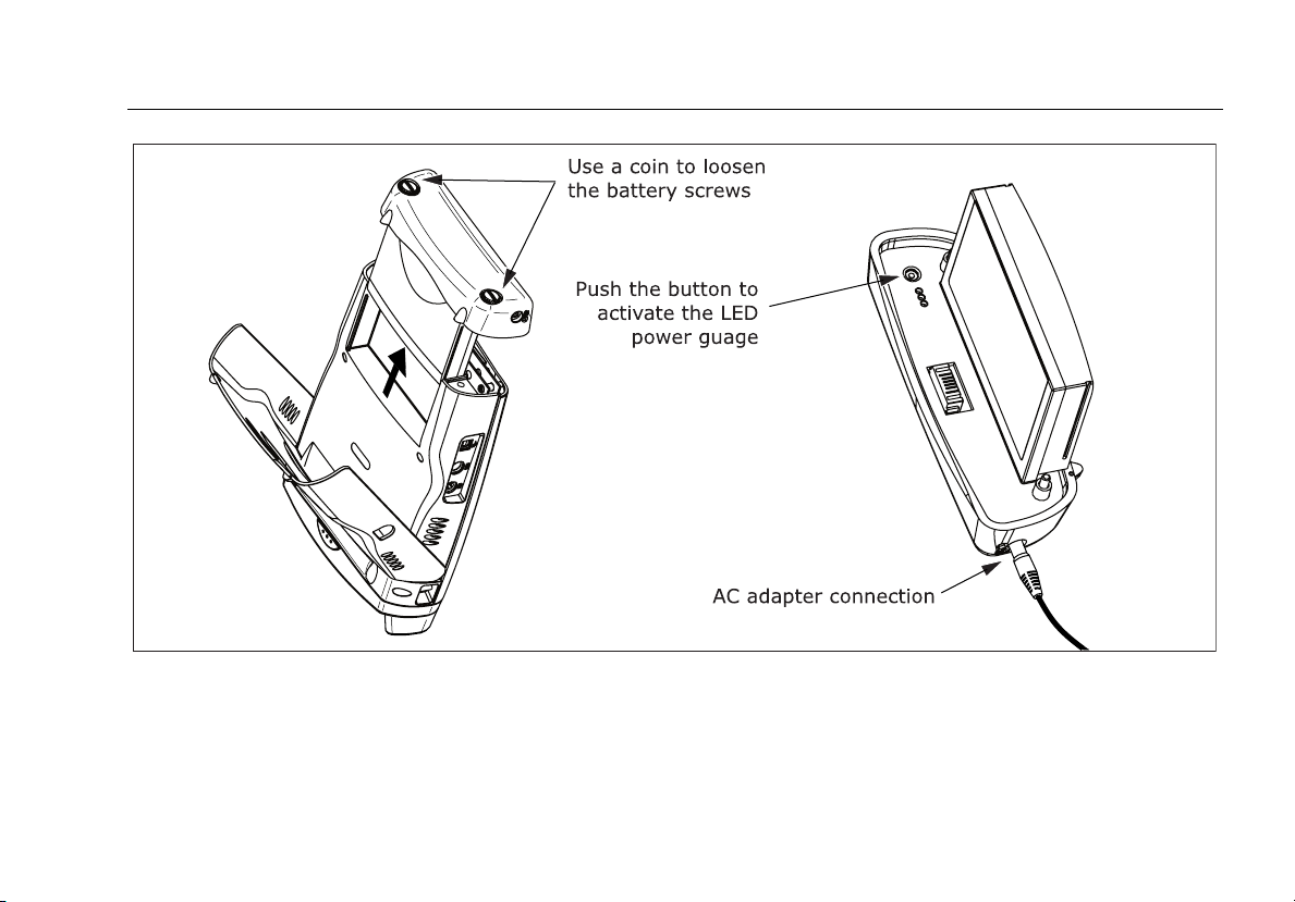
Figure 1. Battery Pack Features
Powering the Tester
ajt20f.eps
13

OF-500 OptiFiber Certifying OTDR
Users Manual
Changing the Language
To change the tester’s language, do the following:
1
Press S.
2
Press N once to select the System tab.
3
Press L to select LANGUAGE; then press t.
4
Use ML to select the desired language; then press
t.
5
Restart the tester to apply the new language.
Additional languages for the tester may be available with
software updates available on the Fluke Networks website.
Use LinkWare software to install or remove languages. See
“Updating the Tester’s Software” on page 92 for details.
Removing and Installing the Module
The tester’s capabilities depend on which test module is
installed. Figure 2 shows how to remove the module.
WCaution
To avoid corrupting the tester's software, always
turn the tester off before removing or installing
a module.
14

Figure 2. Removing the Module
Verifying Operation
Verifying Operation
The tester performs a basic self-test when you turn it on. If
the tester reports an error or does not turn on, refer to “If
Something Seems Wrong” on page 97.
The tester shows the model number of the installed module
in the upper-right corner of the screen. If the screen shows
No Module Installed, Problem with Module, or The module
needs a software update refer to “If Something Seems
Wrong” on page 97.
ajt56f.eps
15
OF-500 OptiFiber Certifying OTDR
Users Manual
Basic Features
The following sections describe the tester's basic features
and introduce the tester's menu system.
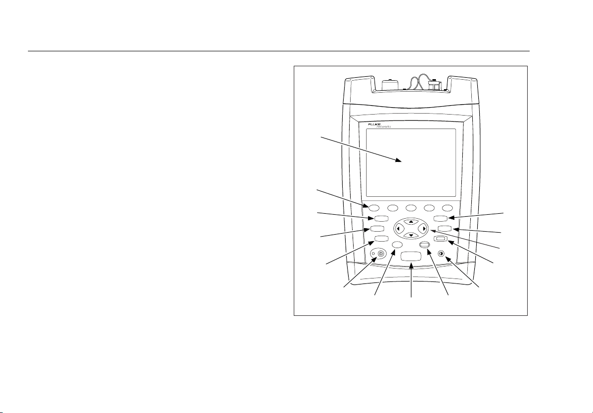
Front Panel Features
Figure 3 describes the tester’s front panel features.
A
N
M
L
K
F1
FUNCTIONS
SETUP
FIBER
INSPECTOR
O
PTIFIBER
F2
HELP
F4 F5
F3
SAVE
VIEW
RECORDS
EXIT
ENTER
TEST
B
C
D
E
16
J
I
Figure 3. Front Panel Features
H
G
F
ajt12f.eps

A
LCD display with backlight and adjustable brightness.
B
s: Saves test results on the removable memory card
or in internal memory.
C
v: Shows the test records saved on the memory card
or in internal memory.
D
K N L M: Navigation keys let you move the cursor or
highlighted area on the screen and increment or
decrement alphanumeric values.
E
e: Exits the current screen.
F
J: Lets you adjust the display brightness.
G
t: Selects the highlighted item on the screen.
H
T: Starts the currently selected fiber test. The test
that will run is shown in the upper-left corner of the
display. To change the test, press
the HOME screen or select a test from the FUNCTIONS
menu.
A Change Test from
Basic Features
I
H: Shows a help topic related to the current screen.
To see the help index, press
J
I: On/off key.
K
f: Activates the optional FiberInspector video probe,
which lets you inspect fiber endfaces and save the images
with test results.
L
F: Shows a list of additional test, configuration, and
status functions.
M
S: Shows the menus you use to configure the tester.
N
A B C D E: The five softkeys provide
functions related to the current screen. The current
functions are shown on the screen above the keys.
H again.
17
OF-500 OptiFiber Certifying OTDR
Users Manual
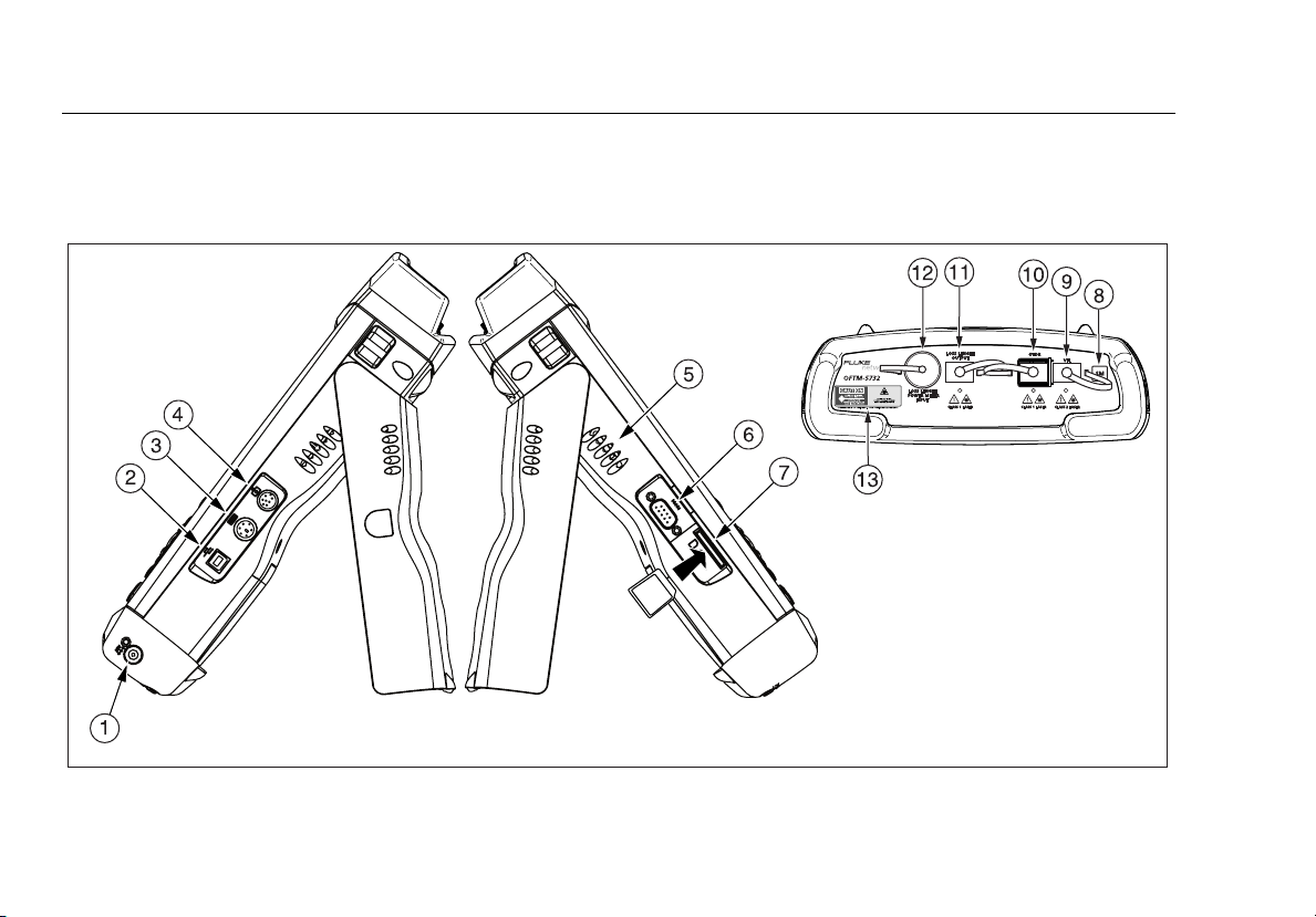
Side and Top Panel Features
Figure 4 describes the tester’s connectors and other features
on the side and top panels.
18
ajt14f.eps
Figure 4. Side and Top Panel Features

A
Connector for the ac adapter. The LED turns on when the
adapter is connected to ac power.
B
USB port for uploading test reports to a PC and downloading
software updates from a PC to the tester. See the LinkWare
documentation for details on using the USB port.
C
Six-pin mini DIN connector for an optional external PS2
keyboard.
D
Eight-pin mini DIN connector for the optional FiberInspector
video probe.
E
Fan vents.
F
RS-232C serial port for uploading test reports to a PC and
downloading software updates from a PC to the tester. See
the LinkWare documentation for details on using the serial
port.
G
Slot for the removable memory card. The LED lights when
the tester is writing to or reading from the memory card.
H
Multimode (MM) or singlemode (SM) label for the module.
Basic Features
I
OFTM-57xx: Connector for the visual fault locator.
J
OTDR connector adapter (SC is standard). The LED
lights when the laser is active.
K
OFTM-5612B/5732: Loss/length output port (SC).
Transmits optical signals for loss/length tests.
L
OFTM-5731/5732/5611B/5612B: Loss/length input port
with interchangeable connector adapter (SC is
standard). Receives optical signals for power
measurements and loss/length tests.
WWarning
Never look directly into optical connectors.
Some sources produce invisible radiation that
can permanently damage your eyes.
M
Laser safety label (shown below).
*
CAUTION
ajt72f.eps
19
OF-500 OptiFiber Certifying OTDR
Users Manual
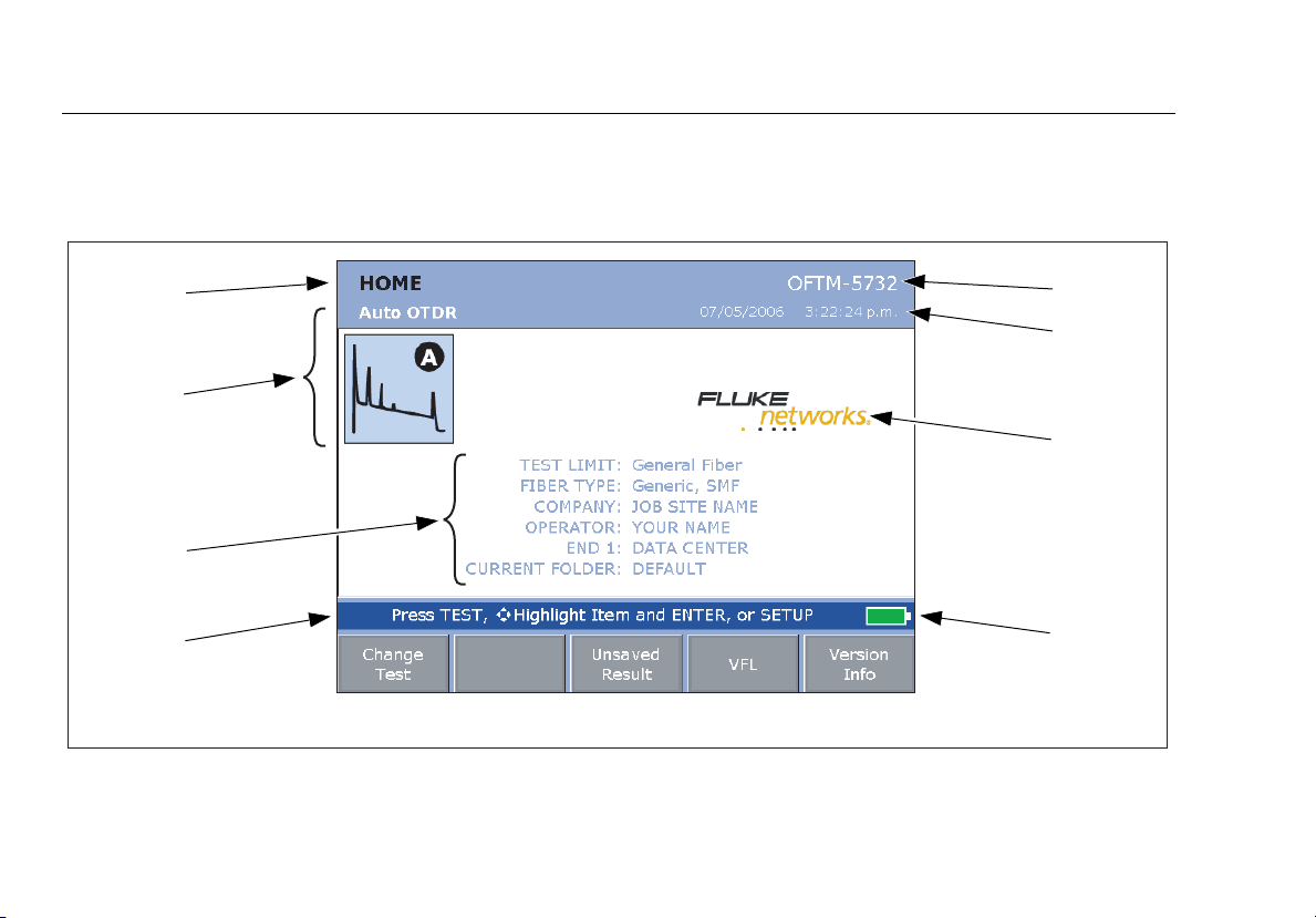
The HOME Screen
The HOME screen shows important test and job settings you
might need to change to configure the tester for your needs.
L
K
J
I
H
Figure 5. Home Screen for OTDR with Loss/Length Option
Figure 5 describes a typical home screen.
G
F
E
A
B
C
D
ajt13f.eps
20
 Loading...