

Page 1

T.O. 33A6-4-30-1
RPM3/HPMS A30000/A 6000-AF
Operation and Maintenance
Manual
NSN 6685-01-470-8667
(2 of 2)
1 August 2000
©2000 DH Instruments, Inc.
Page 2

RPM3/HPMS A30000/ A6000- AF Operation and Mai ntenance Man ual
High pressure liquids and ga ses a re po tentially haza rdous. Energy stored in these liquids and gas es can
be released unexpectedly and with extreme force. High pressure systems should be assembled and
operated only by p ers o nnel who have b een instructed in prop er s a fety pra ctices.
© 2000 DH Instruments, Inc. All rights reserved.
Information in this document is subject to change without notice. No part of this document may be repr oduced or
transmitted in any form or by any means, electronic or mechanical, for any purpose, without the express written
permission of DH Instruments, I nc. 4765 East Beaut iful Lane Phoenix AZ 85044-5318 USA.
DH Instruments makes sincere efforts to ensure accuracy and quality of its published materials; however, no
warranty, expressed or implied, is provided. DH Instruments disclaims any responsibility or liability for any direct or
indirect damages resulting from t he use of the information in this manual or product s descr ibed in it. M ent ion of any
product does not constitute an endorsement by DH Instruments of that product. This manual was originally
composed in English and was subsequently translated into other languages. The fidelity of the t ranslation cannot
be guaranteed. In case of conflict between the English version and other language versions, t he English version
predominates.
DH Instruments, DH, DHI, AutoZ, CalTool, HGC, HPMS, OPG1, PPC, PPC2+, RPM3, SDS (Self Defense System)
are trademarks, r egister ed and ot herwise.
LabVIEW is a registered trademar k of Nat ional Inst r um ent s Corpor at ion.
Document No. 550115
000124
Printed in the USA.
©2000 DH Instruments, Inc.
Page 3

RPM3/HPMS A30000/ A6000- AF Operation and Mai ntenance Man ual
T
AABBLLEE O
T
TABLE OF CONTENTS ................................................................................i
TABLES.................................................................................................... v
FIGURES ................................................................................................. vi
ABOUT THIS MANUAL ............................................................................. vii
1. INTRODUCTION .................................................................................... 1
1.1 PRODUCT OVERVIEW .......................................................................................................................1
1.2 SPECIFICATIONS...............................................................................................................................2
1.2.1 GENERAL SPECIFICATIONS............................................................................................................................... 2
1.2.2 PRESSURE MEASUREMENT SPECIFICATIONS...............................................................................................2
1.2.2.1 RPT MEASUREMENT SPECIFICATIONS (% FS OF ACTIVE RANGE)............................................3
1.2.2.2 ON-BOARD BAROMETER ...................................................................................................................4
2. INSTALLATION.....................................................................................5
2.1 UNPACKING AND INSPECTION .........................................................................................................5
2.1.1 REM OVING FROM PACKAGING.........................................................................................................................5
2.1.2 INSPECTING CONTENTS.....................................................................................................................................5
2.2 SITE REQUIREMENTS........................................................................................................................6
2.3 INITIAL SETUP ...................................................................................................................................6
2.3.1 PREPARING F OR OPERATION...........................................................................................................................6
2.3.2 RPM3/HPMS FRONT AND REAR PANEL S.........................................................................................................7
2.3.2.1 FRONT PANEL......................................................................................................................................7
2.3.2.2 REAR PANEL........................................................................................................................................8
2.3.3 RPM3 FRONT AND REAR PANELS....................................................................................................................9
2.3.4 POWER CONNECTION.......................................................................................................................................10
2.3.5 FOOT SW ITCH CONNECTION........................................................................................................................... 11
2.3.6 TEST PORT CONNE CTION................................................................................................................................11
2.3.7 SETTING UP FILE SEQUENCES .......................................................................................................................12
2.4 POWER UP AND VERIFICATION .....................................................................................................12
2.4.1 APPLY POWER ...................................................................................................................................................12
2.4.2 CHECK PROPER PRESS URE MEASUREMENT OPERATION.......................................................................12
2.5 SHORT TERM STORAGE.................................................................................................................13
2.6 LONG TERM STORAGE AND SHIPPING .........................................................................................13
2.3.2.3 SIDE VIEW ............................................................................................................................................8
2.3.3.1 FRONT PANEL......................................................................................................................................9
2.3.3.2 REAR PANEL......................................................................................................................................10
2.3.6.1 THE RPM3 ATM PORT.......................................................................................................................11
2.4.2.1 CHECKING A B S OLUTE MODE PRESSURE MEASUREMENT.......................................................12
2.4.2. 2 CHECKIN G GA UGE MODE PRESSURE MEA S UREMENT.............................................................13
OFF
C
C
O
O
NTTEE
N
NTTSS
N
3. OPERATION ....................................................................................... 15
3.1 GENERAL/MANUAL OPERATION....................................................................................................15
3.1.1 KEYPAD LAY OUT AND PROTOCOL................................................................................................................15
3.1.2 MAIN RUN SCREE N............................................................................................................................................16
3.1.3 SOUNDS...............................................................................................................................................................17
3.1.4 SOFT [ON/OFF] KEY...........................................................................................................................................17
3.1.5 PRESSURE READY <*>/NOT READY (<↑
↑> OR <↓↓↓↓>) INDICATION................................................................18
↑↑
Page i ©2000 DH Instruments, Inc.
Page 4

RPM3/HPMS A30000/ A6000- AF Operation and Mai ntenance Man ual
3.1.6 MULT IPLE PRESSURE RANGES......................................................................................................................18
3.1.7 AUTOMATE D TEST/CALIBRATION SE QUE NCE S.......................................................................................... 19
3.1.8 HPMS (HIGH PRESSURE MOUNTING SYSTEM)............................................................................................. 20
3.2 DIRECT FUNCTIO N KEYS ................................................................................................................22
3.2.1 DIRECT FUNCTION KEYS SUMMARY.............................................................................................................. 22
3.2.2 [RANGE]...............................................................................................................................................................24
3.2.3 [UNIT] ...................................................................................................................................................................26
3.2.4 [MODE].................................................................................................................................................................27
3.2.5 [UL] (UPPER LIMIT) ............................................................................................................................................ 28
3.2.6 [RES] (RESOLUTION).........................................................................................................................................31
3.2.7 [DISPLAY]............................................................................................................................................................ 33
3.2.8 [HEAD].................................................................................................................................................................41
3.2.9 [SDS] (SELF DEFENSE SYSTEM).....................................................................................................................44
3.2.10 [AUTOZ] ............................................................................................................................................................... 44
3.2.11 [ENTER] RUN TEST SEQUENCE......................................................................................................................49
3.3 [SETUP] MENU KEY.........................................................................................................................54
3.3.1 HEAD....................................................................................................................................................................54
3.3.2 PRESU..................................................................................................................................................................55
3.3.3 READRT (READ RATE)...................................................................................................................................... 56
3.3.4 STAB (STABILI TY)..............................................................................................................................................57
3.3.5 LEAK (LEAK CHECK).........................................................................................................................................59
3.3.6 SEQ....................................................................................................................................................................... 60
3.4 [SPECIAL] MENU KEY......................................................................................................................65
3.4.1 AUTOZ..................................................................................................................................................................66
3.4.2 SDS.......................................................................................................................................................................70
3.4.3 ATM ......................................................................................................................................................................70
3.4.4 REMOTE...............................................................................................................................................................71
3.4.5 RESET..................................................................................................................................................................72
3.4.6 CAL.......................................................................................................................................................................75
3.4.7 INTERN.................................................................................................................................................................75
3.4.8 LEVEL...................................................................................................................................................................78
3.4.9 LOG ......................................................................................................................................................................81
3.1.6.1 RANGES AND IDENTIFICATION....................................................................................................... 19
3.2.5.1 OVER-PRESSURE FUNCT I ON (<PMAX!>)......................................................................................30
3.2.5.2 LO RPT PROTECTION (<!!LO RPT ACTIVE!!> )................................................................................31
3.2.7.1 AVG (AVERAGE) ................................................................................................................................34
3.2.7.2 RATE....................................................................................................................................................36
3.2.7.3 DEV (DEVIATION)...............................................................................................................................36
3.2.7.4 RPT......................................................................................................................................................37
3.2.7.5 HI/LO.................................................................................................................................................... 39
3.2.7.6 FREEZE...............................................................................................................................................39
3.2.7.7 CLEAN.................................................................................................................................................40
3.2.10.1 RUNNING AUTOZ IN GAUGE MEASUREMENT MODE..................................................................44
3.2.10.2 RUNNING AUTOZ IN ABSOLUTE MEASUREMENT MODE............................................................45
3.2.11.1 TEST INITIALIZATION (QUICK SEQUENCE) ...................................................................................51
3.2.11 .2 TEST EXECUTION (QUICK SEQUENCE AND FIL E S E QUENCE )..................................................52
3.3.6.1 SEQUENCE, DA TA.............................................................................................................................61
3.3.6.2 SEQUENCE, FILESEQ .......................................................................................................................62
3.4.1.1 AUTOZ ON/OFF..................................................................................................................................69
3.4.1.2 VIEW AUTOZ.......................................................................................................................................69
3.4.1.3 EDIT AUTOZ........................................................................................................................................70
3.4.5.1 RESET - SETS ....................................................................................................................................73
3.4.5.2 RESET - UNITS...................................................................................................................................74
3.4.5.3 RESET - SEQ......................................................................................................................................74
3.4.5.4 RESET - CAL.......................................................................................................................................74
3.4.5.5 RESET - ALL .......................................................................................................................................75
3.4.7.1 SCRSAV ..............................................................................................................................................76
3.4.7.2 SOUND................................................................................................................................................76
3.4.7.3 TIME.....................................................................................................................................................77
3.4.7.4 ID..........................................................................................................................................................77
4. REMOTE OPE RATION .........................................................................82
4.1 OVERVIEW .......................................................................................................................................82
4.2 INTERFACING ..................................................................................................................................82
4.2.1 RS-232 INTERFACE ............................................................................................................................................82
©2000 DH Instruments, Inc. Page ii
Page 5

RPM3/HPMS A30000/ A6000- AF Operation and Mai ntenance Man ual
4.2.1.1 COM1...................................................................................................................................................82
4.2.2 IEEE-488 (GPIB) ..................................................................................................................................................83
4.3 REMOTE COMMAND SYNTAX AND STYLE.....................................................................................83
4.3.1 LOCAL AND REM OTE SETTING.......................................................................................................................83
4.3.2 COMM AND S YNTAX........................................................................................................................................... 84
4.3.3 QUERIES AND REPL IES....................................................................................................................................84
4.3.4 MULT IPLE COMMANDS..................................................................................................................................... 84
4.3.5 COMMAND P ARAMETERS................................................................................................................................85
4.3.6 SUFFIXES ............................................................................................................................................................ 85
4.3.7 PROGRAMMING TIPS........................................................................................................................................ 85
4.4 COMMANDS .....................................................................................................................................89
4.4.1 ERROR MESSAGES ...........................................................................................................................................92
4.4.2 COMMAND DE S CRIPTIONS.............................................................................................................................. 94
4.5 STATUS SYSTEM...........................................................................................................................124
4.5.1 STATUS REPORTING SYSTEM.......................................................................................................................124
4.5.2 STATUS SUBSYSTEM......................................................................................................................................129
4.2.1.2 COM2...................................................................................................................................................83
4.3.7.1 SCPI AND IEEE-488.2 ........................................................................................................................85
4.3.7. 2 PROGRAMMING TECHNIQUE.......................................................................................................... 86
4.4.2.1 IEEE STD. 488.2 COMMON AND STATUS COMMANDS.................................................................94
4.4.2.2 MEASUREMENT SUBSYSTEM.........................................................................................................97
4.4.2.3 CALCULATE SUBSYSTEM.............................................................................................................. 102
4.4.2.4 CALIBRATION SUBSYSTEM ...........................................................................................................103
4.4.2.5 DISPLAY SUBSYSTEM....................................................................................................................105
4.4.2.6 SENSE SUBSYSTEM.......................................................................................................................106
4.4.2.7 STATUS SUBSYSTEM.....................................................................................................................108
4.4.2.8 SYSTEM SUBSYSTEM.....................................................................................................................116
4.4.2.9 UNIT SUBSYSTEM........................................................................................................................... 122
4.5.1.1 SCPI STATUS SUBSYSTEM............................................................................................................ 124
4.5.1.2 ERROR QUEUE................................................................................................................................124
4.5.1.3 STATUS BYTE REGISTER...............................................................................................................125
4.5.1. 4 STANDARD EVENT REGISTER...................................................................................................... 127
4.5.1.5 RPT READY STATUS REGISTER...................................................................................................128
4.5.2.1 OPERAT ION REGISTER STRUCTURE..........................................................................................129
4.5.2.2 QUESTIONABLE REGISTER ST RUCTURE...................................................................................132
5. MAINTENANCE, CALIBRATIO N AND REPAIR ...................................... 136
5.1 INTRODUCTION .............................................................................................................................136
5.2 RPM3 MAINTE NANCE....................................................................................................................137
5.2.1 AUTOZER O OF RPTS.......................................................................................................................................137
5.2.1.1 GAUGE MODE OPERATION ...........................................................................................................137
5.2.2 ADJUSTMENT OF ON-BOARD BAROMETE R...............................................................................................138
5.2.3 RPM3 OVERHAUL.............................................................................................................................................138
5.3 RPM3 RPT CALIBRATION..............................................................................................................139
5.3.1 PRINCIPLE.........................................................................................................................................................139
5.3.2 EQUIPMENT REQUIRED ..................................................................................................................................141
5.3.3 SET-UP AND PREPARAT ION.......................................................................................................................... 142
5.3.4 RPT CALI BRATION USING RPM3 CALTOOL SOFTWARE..........................................................................142
5.3.5 EDITING AND V IEWING RPT CALIBRATION INFORMATION...................................................................... 143
5.3.6 SETTING ZNATERR.......................................................................................................................................... 144
5.3.7 RPT CALIBRATION/ADJUSTMENT WITHOUT RPM3 CALTOOL SOFTWARE...........................................145
5.4 RPM3 REPAIR ................................................................................................................................146
5.4.1 REMOVING AND REINSTALLING RP M3 IN THE HPMS................................................................................146
5.4.2 OPENING AND CLOS ING THE RPM3 CASE..................................................................................................147
5.4.3 RELOADING RPM3 EMBEDDED SOFTWARE INTO FLASH MEMORY.......................................................148
5.4.4 RPM3 INTERNAL VIEW.................................................................................................................................... 148
5.2.1.2 ABSOLUTE MODE OPERATION .....................................................................................................137
5.3.1.1 PA/PM COEFFICIENTS.................................................................................................................... 140
5.3.1.2 SETTING ZNATERR......................................................................................................................... 140
5.3.1. 3 ORDER OF OPE R A TIONS...............................................................................................................141
5.3.1.4 AS RECEIVED/AS LEFT DATA........................................................................................................141
5.4.4.1 SDS MODULE ...................................................................................................................................149
5.4.4.2 RPTS..................................................................................................................................................149
5.4.4.3 POWER SUPPLY..............................................................................................................................149
Page iii ©2000 DH Instruments, Inc.
Page 6

RPM3/HPMS A30000/ A6000- AF Operation and Mai ntenance Man ual
5.4.4.4 COOLING FAN..................................................................................................................................149
5.4.4.5 MICRO BOARD.................................................................................................................................149
5.4.4.6 MAIN BOARD....................................................................................................................................149
5.4.4.7 ON-BOARD BAROMETER ...............................................................................................................149
5.4.4.8 DISPLAY............................................................................................................................................149
5.5 HPMS MAINTENANCE....................................................................................................................150
5.5.1 HPMS OV E RHAUL............................................................................................................................................ 150
6. TROUBLESHOOTING......................................................................... 152
6.1 OVERVIEW .....................................................................................................................................152
7. APPENDIX ........................................................................................ 157
7.1 PRESSURE UNIT CONVERSIONS..................................................................................................157
7.2 WARRANTY STATEMENT..............................................................................................................158
8. GLOSSARY....................................................................................... 161
©2000 DH Instruments, Inc. Page iv
Page 7

RPM3/HPMS A30000/ A6000- AF Operation and Mai ntenance Man ual
T
AABBLLEES
T
Table 1. RPM3/HPMS A 30000/A6000-AF Supplied Items...................................................................5
Table 2. RPM3 Range Identific ation Summary..................................................................................19
Table 3. Summary of RPM 3 Dir ect Function Key Operation..............................................................23
Table 4. PresU - Available Units .......................................................................................................56
Table 5. READRT - Display Updat e Rates........................................................................................56
Table 6. Functions - S ec ur ity Levels .................................................................................................79
Table 7. RPM3 COM1 DB-9F P in Designations ................................................................................82
Table 8. IBM PC/XT DB-9F, DB- 9M Connec tions .............................................................................82
Table 9. RPM3 COM2 DB-9M P in Des ignations................................................................................83
Table 10. Quick Programm ing Tips.....................................................................................................88
Table 11. Command Summary ...........................................................................................................89
Table 12. “SYSTEM:ERROR?” QUERY REPLY.................................................................................93
Table 13. 8 Bit Status Byte Register .................................................................................................125
Table 14. Standard Event Regis ter...................................................................................................127
Table 15. 8 Bit RPT Ready Status Register ......................................................................................128
Table 16. Troubleshooting Sym ptom/Probable Cause/S olution List...................................................152
Table 17. Pressure Unit of M eas ur e Conv er s ions .............................................................................157
Table 18. DH Instrument s, Inc. Authorized Service Prov ider s .........................................................159
S
Page v ©2000 DH Instruments, Inc.
Page 8

RPM3/HPMS A30000/ A6000- AF Operation and Mai ntenance Man ual
F
Figure 1. RPM3/HPMS Front P anel .....................................................................................................7
Figure 2. RPM3/HPMS Rear Panel......................................................................................................8
Figure 3. RPM3/HPMS Side View........................................................................................................8
Figure 4. RPM3 Front Panel ................................................................................................................ 9
Figure 5. RPM3 Rear Panel...............................................................................................................10
Figure 6. RPM3 Keypad.....................................................................................................................15
Figure 7. RPM3/HPMS Front P anel ...................................................................................................21
Figure 8. RPM3/HPMS Internal S c hem atic.........................................................................................22
Figure 9. Status Byte Regist er .........................................................................................................125
Figure 10. Illustration of t his S tructure Duplicat ed for Each of the OPERation, INS Trument, and
Figure 11. Relationship of the OPERation Register and It s S uppor t Registers....................................131
Figure 12. Illustration of t his S tructure Duplicat ed for Each of the OPERation, INS Trument, and
Figure 13. Relationship of the QUEStionable Register and It s S uppor t Registers...............................134
Figure 14. RPM3/HPMS Side View....................................................................................................147
Figure 15. RPM3 Internal View..........................................................................................................148
G
IIG
F
ISUMmary Registers.........................................................................................................130
ISUMmary Registers.........................................................................................................133
URREESS
U
©2000 DH Instruments, Inc. Page vi
Page 9

RPM3/HPMS A30000/ A6000- AF Operation and Mai ntenance Man ual
A
A
This manual provides the user with the basic information necessary to operate an RPM3/HPMS
A30000/A6000-AF Reference Pressure Monitor with High Pressure Mounting System. It also
includes a great deal of addit ional information provided to help you opt imize use of t he instrument
and take full advantage of its many features and functions.
Before using this manual, take a moment to f amiliarize yours elf with the T able of Content s struc ture.
All first time users should read Chapter 2. Chapter 3 provides a comprehensive description of
general RPM3/HPMS operating principles. Section 3.1.7 describes the automated Sequence
function used to run calibrations and verifications of typical ins truments under test . This is the way
the instrument is typically used. Chapter 4 is for remote operation from an external computer.
Chapter 5 provides maintenance and calibration information. Chapter 6 is a quick troubleshooting
guide. Use it to troubleshoot unexpected RPM3/HPMS behavior based on the symptoms of that
behavior. Certain words and expr essions hav e specif ic meaning as t hey pert ain to t his produc t. The
Glossary is usef ul as a quick ref erence f or exact definit ion of specif ic words and expr essions as t hey
are used in this manual.
RPM3/HPMS A30000/A6000-AF is usually delivered as part of an HGC-30000-AF system which
includes an OPG1 hydraulic pressure generator/controller. The OPG1 has its own Operation and
Maintenance M a nual.
O
BBO
UTT
U
T
HIISS
H
T
M
M
N
AAN
UAALL
U
FOR THOSE OF YOU W HO “DO N’T RE AD M ANUAL S”, GO DIRE CTL Y T O SEC TION 2 .3 TO SE T UP YOUR
RPM3/HPMS AND THEN 2.4 FOR POWER UP AND VERIFICATION. THIS WILL GET YOU RUNNING
QUICKLY WITH MINIMAL RISK OF CAUSING D AMAGE TO YOURSE LF OR YOUR NE W RPM3. THE N…
WHEN YOU HAVE QUESTIONS OR START TO WONDER ABOUT ALL THE GREAT FEATURES YOU
MIGHT BE MISSING, GET IN TO THE M ANUAL!
Manual Conventions
(CAUTION) is us ed throughout the m a nua l to identify user w a rnings a nd cautions.
(NOTE) is used throughout the manual to identify operating and applications advice and
additional explanations.
[ ] indicates direct function keys (for example [RANGE]).
< > indicates RPM3 scr een dis play s ( for example <1yes>).
Page vii ©2000 DH Instruments, Inc.
Page 10

RPM3/HPMS A30000/ A6000- AF Operation and Mai ntenance Man ual
N
N
OOTTEES
S
©2000 DH Instruments, Inc. Page viii
Page 11

RPM3/HPMS A30000/ A6000- AF Operation and Mai ntenance Man ual
1. INTRODUCTION
1.1 PRODUCT OVERVIEW
RPM3/HPMS A30000/A6000-AF is the combination of an RPM3 A5000/A6000-AF reference
pressure monitor and an HPMS High Pressure Mounting System. The combination of an
RPM3/HPMS A30000/A6000-AF and an OPG1-AF oil pressure generator make up the
HGC-30000-AF hydraulic gauge calibrator. The OPG1-AF has it s own Operation and Maintenance
manual.
RPM3 A30000/A6000-AF is a stand-alone, microprocessor driven, reference pressure monitor
intended to accurat ely measure oil pressure in a variety of pressure calibr ation, measurement and
testing applications . It has been designed t o provide very high perfor mance and extensiv e features
combined with maximum v er s atility and ease of use. RPM3 A30000/A6000-AF is a special version of
the standard DHI RPM3 product configured specifically for the USAF HGC-30000-AF hydraulic
gauge calibrator.
The HPMS mounts the RPM3 at a conv enient viewing angle and c ontains t he hardware t o isolat e the
RPM3’s low pressure tr ans ducer (A6000) when the high press ure transducer (A30000) is in use.
RPM3 A30000/A6000-AF uses tw o high accurac y ref erence pres sure t ransduc ers (RP Ts) and an onboard barometer t o m eas ur e pr es s ur e.
RPM3 A30000/A6000-AF is controlled locally by the operator using its front panel display, keypad
and foot pedal or remot ely by a computer using ASCI I character command strings over its RS-232
and IEEE-488 interfaces.
RPM3 A30000/A6000-AF has s ix pressure m easurement r anges from 0 t o 2 000 psi (7 MPa) t o 0 to
30 000 psi (200 MPa) in gauge and absolut e m eas ur em ent modes.
RPM3/HPMS A30000/A6000-AF is usually delivered as part of an HGC-30000-AF system which
includes an OPG1 hydraulic pressure generator/controller. The OPG1 has its own Operation and
Maintenance M a nual.
Page 1 ©2000 DH Instruments, Inc.
Page 12

RPM3/HPMS A30000/ A6000- AF Operation and Mai ntenance Man ual
1.2 SPECIFICATIONS
1.2.1 GENERAL SPECIFICATIONS
Power Requirements: 85 to 264 VAC, 47 to 440 Hz , 18 VA max consumption
Operating Temperature Range: 15 to 45 °C
Storage Temper ature Range: -20 to 70 °C
Weight: RPM3: 3.5 kg ( 7.7 lb)
Dimensions: 21.5 cm H x 29 cm W x 38 cm D
Microprocessor: Motorola 68302, 16 MHz
Communication Port s : RS-232 (COM1), RS-232 (COM2), I EEE-488
Pressure Ranges: 2 000 psi (14 MPa), 4 000 ps i ( 28 M P a) , 6 000 psi
Operating Medium: Oil (Di-ethyl hexy l s ebac ate)
Pressure Connections:
Test port (RPT > 10 000 psi): DH500 (gland and c ollar type for coned and left hand
Pressure Limits:
Maximum working pressure:
Maximum pressur e w/o damage:
HPMS: 5.8 kg (12.8 lb)
RPM3/HPMS: 9.3 kg (20.5 lb)
(8.5 in. x 11.5 in. x 15.0 in.) approx .
(42 MPa), 10 000 psi ( 70 M P a) , 18 000 psi (126 MPa),
30 000 psi (200 MPa) gauge and absolut e.
threaded tube, equivalent to AE F250C, HIP HF4, etc.)
30 000 psi (214 MPa)
37 000 psi (255 MPa)
1.2.2 PRESSURE MEASUREMENT SPECI FICATIONS
RPM3 A30000/A6000-AF is configured with two reference pressure transducers (RPT).
Each transducer has three ranges. The RPTs are of the absolute pressure type with an
evacuated, permanently sealed reference. Absolute RPTs measure both absolute and
gauge pressure. Gauge pressures are defined by offsetting atmospheric pressure
dynamically with compensation for atmos pher ic c hanges us ing an on board barometer.
©2000 DH Instruments, Inc. Page 2
Page 13

RPM3/HPMS A30000/ A6000- AF Operation and Mai ntenance Man ual
1.2.2.1 RPT MEASUREMENT SPECIFICATIONS (% FS OF ACTIVE RANGE)
Transducer Type: Oscillating quart z resonator
Warm Up Time: 30 minutes for operation within s pec ifications
Resolution: To 1 ppm, user settable by individual range
Overpressur e Lim its:
Without effect on calibration:
Without perm anent damage:
Temperature E ffect: ± 0.008 % max imum temper ature eff ect in normal
Acceleration Affect: ± 0.008 % /g maximum, worst axis
Precision
Stability
1
: Range: H3: 0.0150 %
2
:
Gauge Mode (w/Autozero):
Absolute Mode (w/ A utozero):
Measurement Uncer tainty
3
:
Gauge Mode (w/Autozero):
Absolute Mode (w/ A utozero):
115 % of Range 3
125 % of Range 3
ambient operating range of 15 to 45 °C
Ranges H1, H2: 0.0125 %
Ranges L1, L2, L3: 0. 010 %
All Ranges
0.008 %
0.008 %
H3 H2, H1
0.017 % 0.015 % 0.013 %
0.017 % 0.015 % 0.013 %
L1, L2, L3
1 Precision: Combined linearity, hysteresis, r epeatability of measurement s made by the
reference pressure transducer. When using an absolute RPT for gauge mode
measurement add
account the resolution and short term stability of the on-board barometer used for
dynamic atmospheric pressure compensation.
2 Stability: Maximum change in zero and span over 180 days for t ypical tr ansducer us ed
under typical conditions. As stability can only be predicted and varies from transducer to
transducer, stability for a specif ic RPT should be established from exper ience.
3 Measurement Uncertainty: Combined precision, st ability, temperature effect.
± 2.5 Pa (0.00035 psi) to the precision specification to take into
Page 3 ©2000 DH Instruments, Inc.
Page 14

RPM3/HPMS A30000/ A6000- AF Operation and Mai ntenance Man ual
1.2.2.2 ON-BOARD BAROMETER
Sensor Technology: Micro-machined silicon
Warm Up Time: None required
Resolution: 1.25 Pa (0.00018 psi)
The on-board barom eter is NOT used as a so urce of absolute accuracy. It is used
only to measure changes in atmospheric pressure for dynamic compensation of the
atmospheric pressure offset when using an absolute reference pressure transducer
to make gauge pressure measurements (see Section 3.4.1, Gauge Mode with an
Absolute RPT, Dynamic Compensation for Atmospheric Pressure).
©2000 DH Instruments, Inc. Page 4
Page 15
RPM3/HPMS A30000/ A6000- AF Operation and Mai ntenance Man ual
2. INSTALLATION
2.1 UNPACKING AND INSPECTION
RPM3/HPMS A30000/A6000-AF is usually delivered as part of an HGC-30000-AF system which
includes an OPG1 hydraulic pressure generator/controller. The OPG1-3000-AF is shipped in a
separate corrugated conta ine r a nd ha s its O p er a tio n a nd Maintenance Manual.
2.1.1 REMOVING FROM PACKAGING
RPM3/HPMS A30000/A6000-AF is delivered, along with its accessories, in a reusable
molded plastic, shipping c ontainer with polyurethane ins er ts to hold it in place.
Remove the RPM3/H P M S A 30000/A6000-AF and its ac c es s ories from the shipping container
and remove each element from its protec tive plastic bag.
Retain the shipping conta iner for repacking the RPM3/HPMS A3 0000/A6000-AF when it is
shipped for recalib ration of repair.
2.1.2 INSPECTING CONTENTS
Check that all item s are present and have NO vis ible dam age.
A standard RPM3/ HP M S A 30000/A6000-AF includes all items listed in Table 1.
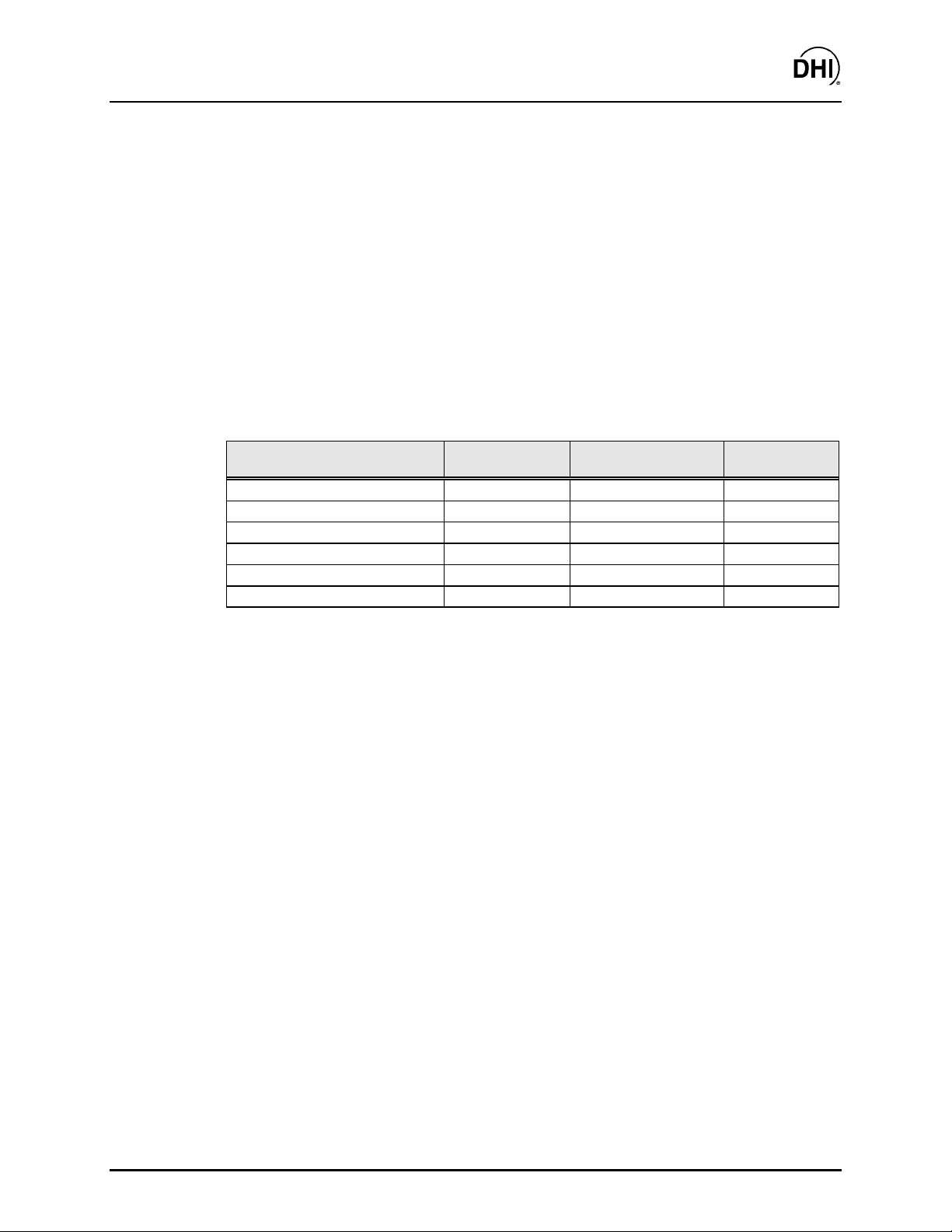
Table 1. RPM3/HPMS A30000/A6000-AF Supplied Items
DESCRIPTION PART NO.
RPM3/HPMS A30000/A6000-AF Reference Pressure Monitor/ High Pressure
Mounting System
Transport case (with inserts) ( used f or or iginal shipment) 123122
Foot Switch Assembly 401613
Operation and Maintenance Manual, RPM3/HPMS A30000/A6000 550115
Calibration Certificate 550100
Test Report, HGC-30000-AF ( if RPM3/ HPMS delivered as par t of HG C-30000- AF
system)
Accessories: 401605
Power Cord (7.5 ft.) 100770
General Accessories Disk (Important: I ncludes syst em suppor t sof t war e and
documentation)
RPM3 CalTool Manual 550106
401604
550116
102987
Page 5 ©2000 DH Instruments, Inc.
Page 16

RPM3/HPMS A30000/ A6000- AF Operation and Mai ntenance Man ual
2.2 SITE REQUIREMENTS
The RPM3/HPMS A30000/A6000-AF is typically delivered as part of an HGC-30000-AF hydraulic
gauge calibrator that includes an OPG1-30000-AF that has its own Operation and
Maintenance Manual. See the OPG1-30000- AF Operation and Maint enance Manual for infor mation
on site requirement s for the HGC-30000-AF.
Install RPM3/HPM S A30000/A6000-AF on any stable surface at a convenient height. Consider t he
placement of the FOOT SWITCH which may need to be accessed frequently while
running calibrations.
Support facilities required f or RPM3/HPMS A30000/A6000- AF include an electrical power sour ce of
85 to 264 VAC, 47 to 440 Hz .
2.3 INITIAL SETUP
2.3.1 PREPARING FOR OPERATION
To prepare RPM3/ HP M S A 30000/A6000-AF for c hec k out and operation:
• Remove the plastic plug from the RPM3/HPMS A30000/A6000-AF rear panel
TEST connection.
• Remove the protective plastic sheet from the RPM3 f r ont panel display.
• Familiarize yourself briefly with the RPM3 and HPMS f ront and rear panels ( see Sect ions
2.3.2, 2.3.3).
©2000 DH Instruments, Inc. Page 6
Page 17
RPM3/HPMS A30000/ A6000- AF Operation and Mai ntenance Man ual
2.3.2 RPM3/HPMS FRONT AND REAR PANELS
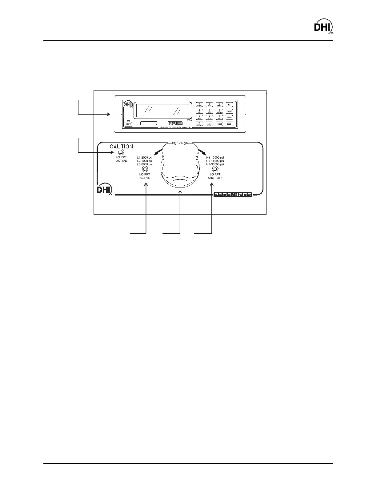
2.3.2.1 FRONT PANEL
5
4
3
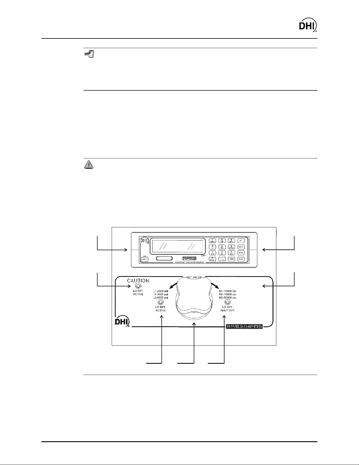
1. Lo RPT Shut Off Valve Position LED
2. Lo RPT Shut Off Valve Knob
3. Lo RPT Active Valve Position LED
4. Caution Lo RPT Active LED
5. RPM3 A30000/A6000-AF Reference Pressure Monitor
2
1
Figure 1. RPM3/HPMS Front Panel
Page 7 ©2000 DH Instruments, Inc.
Page 18
RPM3/HPMS A30000/ A6000- AF Operation and Mai ntenance Man ual
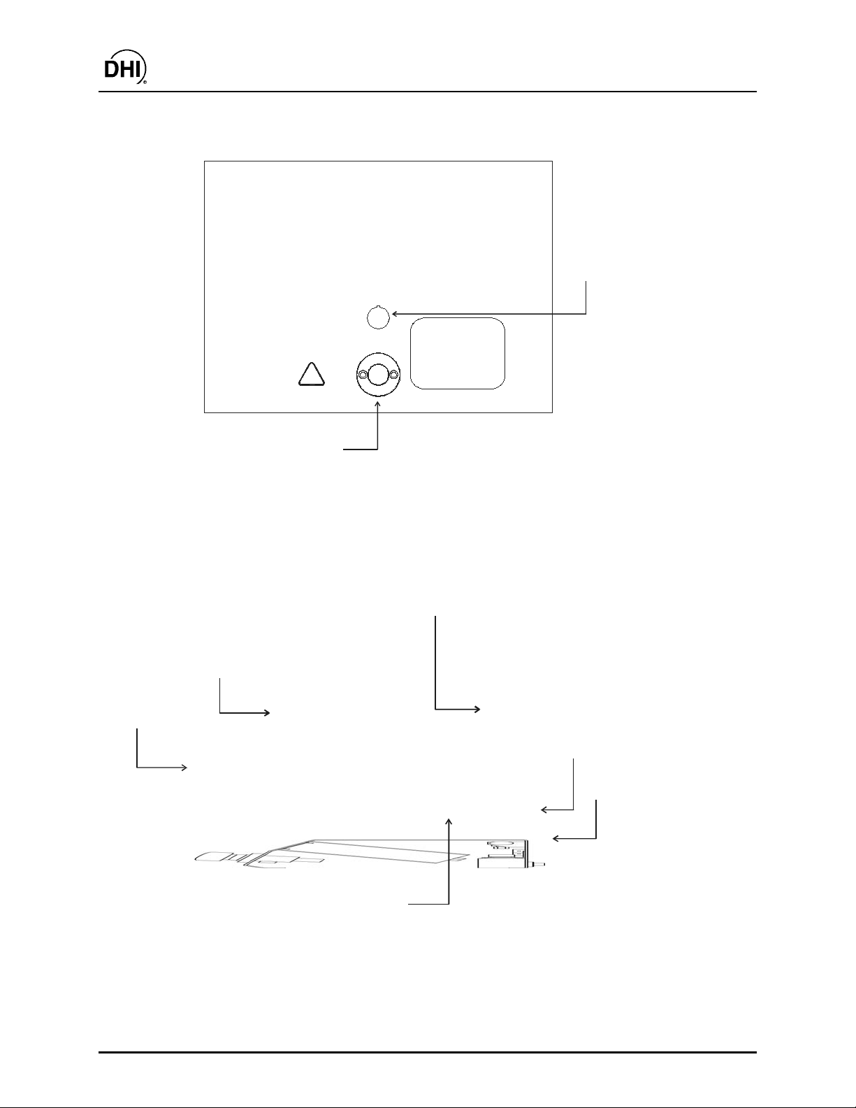
2.3.2.2 REAR PANEL
DH Instrume nts, Inc.
4765 East Beautiful Lane
Phoenix AZ 85044- 5318
USA
Tel 602.431.9100
Fax 602.431.9559
dhi@dhinstruments.com
www.dhinstruments.com
Made in USA
!
1. Foot switch (Remote [ENTER]) cable connection
2. TEST port (DH500 F)
Figure 2. RPM3/HPMS Rear Panel
2.3.2.3 SIDE VIEW
2
DO NOT
EXCEED
30000 psi
(200 MPa)
2
FOOT
SWITCH
TEST
1
3
1
6, 7
1. Lo RPT Isolation Valve Control Knob 5. TEST port (DH500 F)
2. RPM3 A30000/A6000-AF Reference Pressure Monitor 6. Electrical Power Connector (IEC320-C13)
3. Lo RPT Pressure Relief Valve 7. Foot switch (remote [ENTER]) connector
4. Oil Collection Cup (from Relief Valve)
Figure 3. RPM3/HPMS Side View
©2000 DH Instruments, Inc. Page 8
4
5
Page 19
RPM3/HPMS A30000/ A6000- AF Operation and Mai ntenance Man ual
2.3.3 RPM3 FRONT AND REAR PANELS
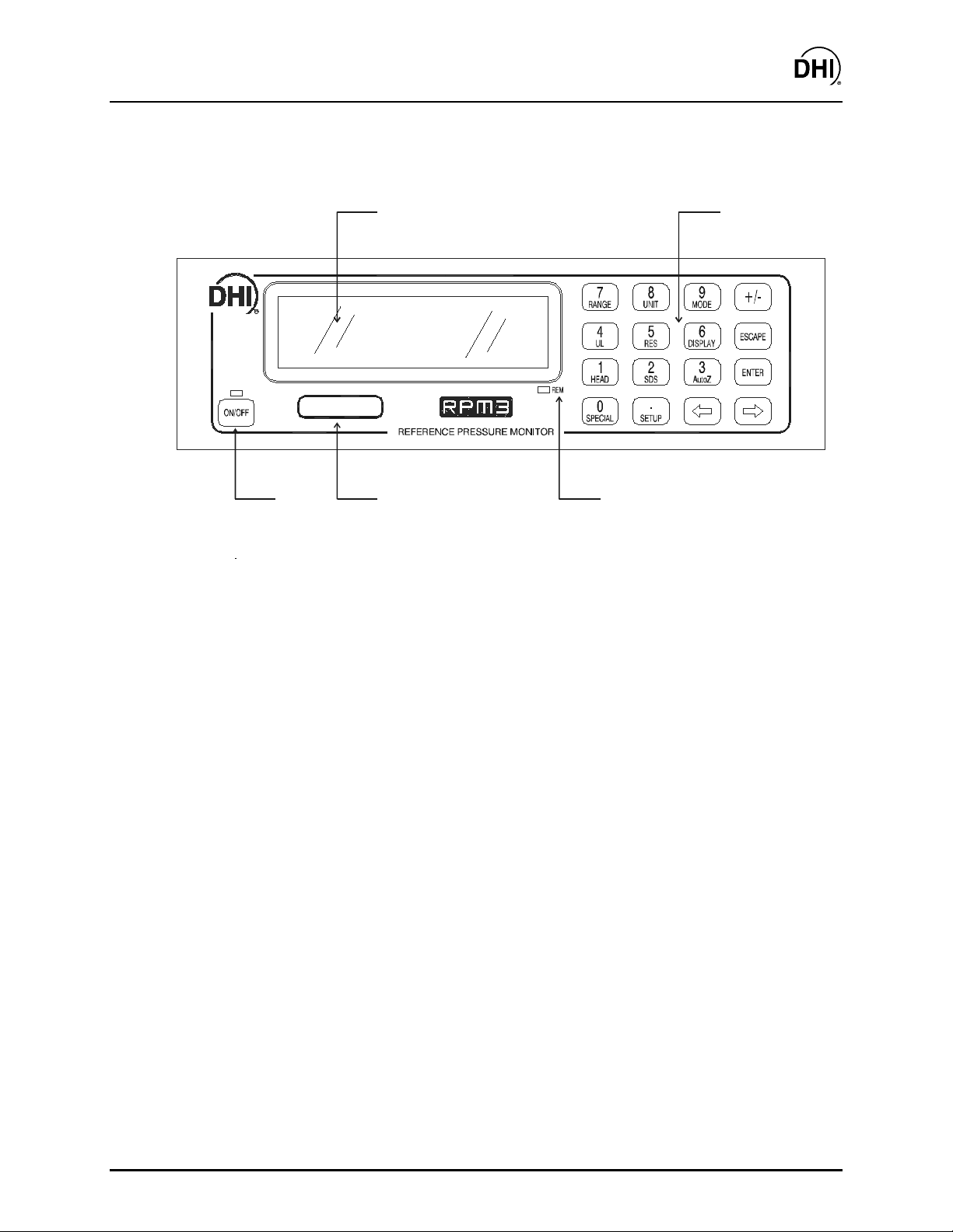
2.3.3.1 FRONT PANEL
1
2
345
1. Display 4. RPT designator label
2. Multi-Function Keypad 5. Soft ON/OFF key and indicator
3. Remote Indicator
Figure 4. RPM3 Front Panel
Page 9 ©2000 DH Instruments, Inc.
Page 20
RPM3/HPMS A30000/ A6000- AF Operation and Mai ntenance Man ual
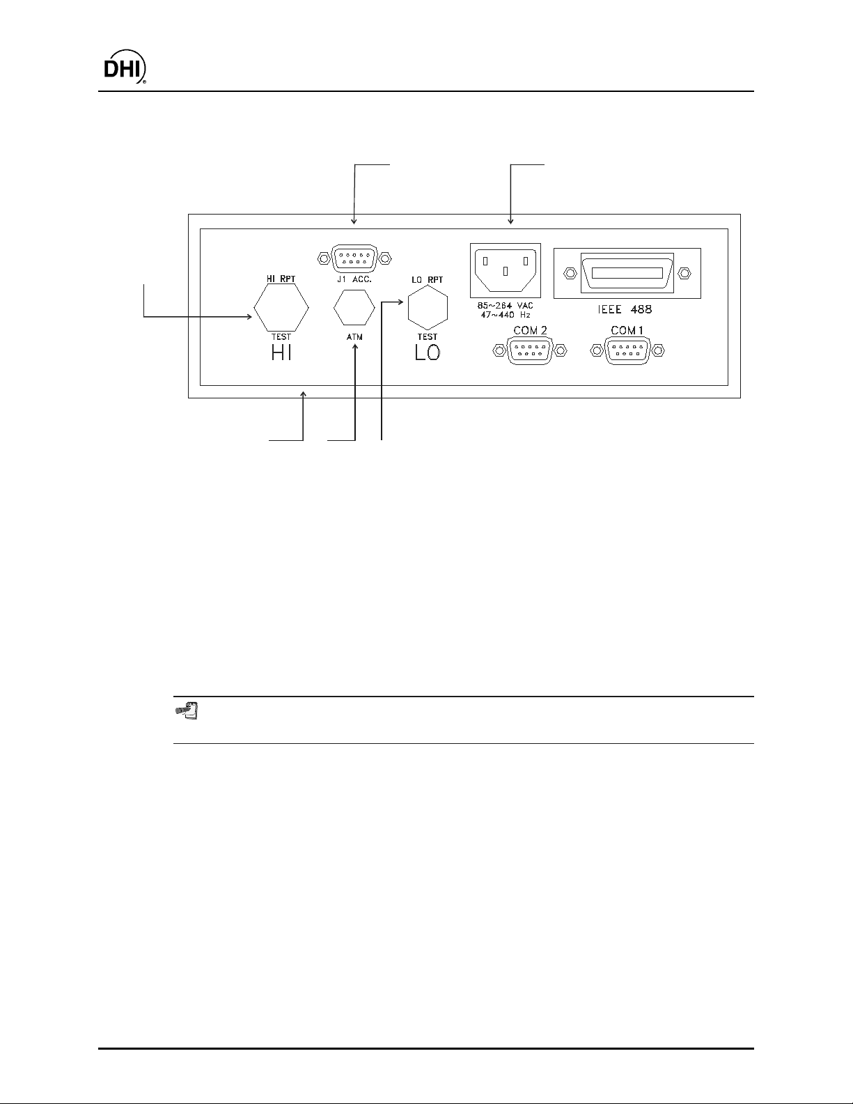
2.3.3.2 REAR PANEL
1
6
5
1. Accessories Connection Cable (connects to HPMS 4. ATM Post (On-Board Barometer)
Rear panel FOOT SWITCH and HPMS LEDs) (10-32 UNF)
2. Electrical Power Connector (IEC320-C13) 5. Label, Product (on bottom of case)
3. LO TEST Port (A5000 RPT) (1/8 in. NPT F) 6. HI TEST Port (A30000 RPT) (DH500 F)
4
3
2
Figure 5. RPM3 Rear Panel
2.3.4 POWER CONNECTION
• Connect the power cable t o the RPM3 rear panel electr ic al power connector.
• Do NOT connect the other end of the power c able to a power source yet.
RPM3 is always powered and active when power is supplied through the rear panel
power co nne ctor. The front p a nel O N/OFF key co ntrols a soft O N /O F F (s e e Se ctio n 3.1.4).
©2000 DH Instruments, Inc. Page 10
Page 21

RPM3/HPMS A30000/ A6000- AF Operation and Mai ntenance Man ual
2.3.5 FOOT SWITCH CONNECTION
Connect the foot switch supplied in the RPM3/HPMS ac cessories to the HPMS rear panel
electrical connection labeled FOOT SWITCH. Place the foot switch on the floor at a
convenient location. The FOOT SWITCH function is equivalent to the RPM3 front panel
[ENTER] key and may be used fr equently while running tests and c alibr ations.
2.3.6 TEST PORT CONNECTION
A single high pressure TEST port is prov ided on the rear panel of the HPM S .
The test port connection is a DH500 F. DH500 is a gland and collar ty pe fitting f or 1/4 in.
(6 mm) coned and left hand threaded tube. DH500 is equivalent to AE F250C, HIP HF4, etc.
Connecti on to OP G1 if the RPM3/HPMS is Part of an HGC-30000-AF S yst em
If the RPM3/HPMS was delivered as part of an HG C-30000-AF Hydraulic G auge Calibrator,
an OPG1 Oil Pressure Generator/Controller was delivered with it. The OPG1 includes a
fittings kit with the necessary fittings to interconnect the RPM3/HPMS and OPG1 and
instructions on making the connection. S ee the OPG1-30000-A F manual.
USE THE CORRECT PRESSURE CONNECTORS: The RPM3/HPMS TEST port fitting is a
DH500 F (see Section 1.2.1). It is NOT a 1/8 in. NPT F . Never use fittings other than the
correspo nding male fittings in these connec tors. D amage to the connecto rs and d angerous
failure under pressure co uld res ult from using incorrect fittings.
DO NOT AP PLY PRESSURE UN TIL YOU ARE FAM ILIAR WITH OPERATION : The RPM3/HPMS
rear panel test port connects internally to both the RPM3’s 6 000 psi (40 MPa) and
30 000 psi (200 M Pa)RPTs. T he valve on the front o f the HPMS isolate s the low press ure
RPT when the high pressure RPT is in use. Do not app ly pressure to the RPM3/HPMS until
you are familiar with its operation and know how to protect the low pressure RPT from
overpressure (see Section 3.1.8). FAILURE TO PROTECT THE LOW PRESSURE RPT FROM
OVERPRESSURE MAY DESTROY IT. DAMAGE D UE T O RP T OV ERPRESSURE IS NO T COVERE D
BY THE PRODUCT WARRANTY.
2.3.6.1 THE RPM3 AT M PORT
The ATM pass through on the RPM3 rear panel is connected to the RPM3’s onboard barometer. This connection assures that the on-board barometer measures
ambient atmospher ic pressure rather than the press ure inside the RPM3 case that
may vary slightly from ambient pressure. The ATM port should be left open
and unobstructed.
NEVE R plug or obs truct the ATM pas s through as this ma y adverse ly affect gauge
mode operation and autozeroing on an absolute transducer.
Page 11 ©2000 DH Instruments, Inc.
Page 22

RPM3/HPMS A30000/ A6000- AF Operation and Mai ntenance Man ual
2.3.7 SETTING UP FILE SEQUENCES
RPM3 supports automated test/calibration sequences. Sequence parameters for testing
specific DUTs can be stored in Sequence Files and recalled when a Sequence is run.
Consider setting up Sequence Files for frequently t ested DUTs as part of t he RPM3 set up
process (see Section 3.3.6).
2.4 POWER UP AND VERIFICATION
2.4.1 APPLY POWER
Connect the RPM3 power cable to an electric supply of 85 to 264 VAC (47 to 440 Hz).
Observe the front panel display as RPM3 initializes, error checks and goes to the main run
screen (see Sect ion 3.1. 2). Check t hat one of the t wo green Valve St atus LEDs on t he front
panel of the HPMS is lit (the red LED should NO T be ON).
RPM3 is always powered and active when power is supplied through the rear panel
power connector. The front panel ON/OFF key controls a soft ON/OFF function (see
Section 3.1. 4).
If the RPM3 fails to reac h the main run sc reen, servic e is required. Recor d the sequence of
operation and displays observed and contact a DHI Authorized Service Center (see
Section 7.2, Table 18).
If neither of the green LEDs on the HPMS front panel lights, check that the 9-pin D-Sub
accessory cable at the rear of the RPM3 itself is properly connected to the ACC. J1
connector.
The active range o n power up is the sam e as the range that was active at the last power
down (see Section 3.1.6).
2.4.2 CHECK PROPER PRESSURE MEASUREMENT OPERATION
2.4.2.1 CHECKING ABSO L UT E MODE PRESSURE MEASUREMENT
Check that the RP M 3 RP Ts operate properly in abs olute mode.
Open the RPM3/HP MS TES T port t o atmosphere. Put the valv e knob in the HPMS
front panel into the Lo RPT Active position. This opens the Lo RPT t o the HPMS
TEST port.
Press [MODE] on the RPM3 and select absolute. Change the pressure unit of
measure using [UNIT] if desired (see Sec tion 3.2.3).
Observe the RPM3 indicated pressure. Check that t he value is equal to at mospheric
pressure
[RANGE] and [ENTER] to change ranges. Check that the values of atmospheric
pressure measured by the different ranges agree with each other within RPM3
measurement tolerances (see Section 1.2.2.1). If they do NOT agree within
©2000 DH Instruments, Inc. Page 12
± 5 psi. Repeat this process for all the ranges on both RPTs using
Page 23

RPM3/HPMS A30000/ A6000- AF Operation and Mai ntenance Man ual
tolerances, RPM3 may need calibration or repair.
2.4.2.2 CHECKING GAUGE MODE PRESSURE MEASUREM ENT
Open the RPM3/HP MS TES T port t o atmosphere. Put the valv e knob in the HPMS
front panel into t he Lo RPT Active position. This opens the Lo RPT t o the TEST
port.
Press [MODE] on the RPM3 and select gauge. Change the pressure unit of
measure using [UNIT] if desired (see Sec tion 3.2.3).
The value indicated should be near z ero (
then press [AutoZ]. This runs AutoZ to zero the range (see S ection 3.2.10). Upon
return to the m ain run screen, observe that the indication of m easured pr essure has
zeroed.
Use [RANGE] and [ENTER] to change ranges (see Section 3.2.2) and repeat the
zeroing process for each range (the two minute wait does not need to be repeated
each time).
If a range fails to zero properly, RP M 3 m ay need r epair .
It is normal for RP M3 to indicate a value o ther than zero when vented when gauge
mode is first entered or ra nges are changed, especially if Auto Z is OFF, RPM3 ha s
been OFF for so me time, its location ha s changed or the fluid head to which it is
connected has changed.
± 5 psi, 35 kPa). W ait two minutes and
2.5 SHORT TERM STORAGE
The following is recomm ended for short ter m s torage of RPM3/HPM S :
• Vent the RPM3/ H P M S TEST port.
• Disconnect the power s upply .
When RPM3 will NOT be us ed for some t ime, it m ay be left powered, but use the soft ON/OFF key
to turn OFF the display.
2.6 LONG TERM STORAGE AND SHIPPING
The following is recommended for long term storage and or shipping of RPM3/HPMS:
• Plug the HPMS TE S T port.
• Place the RPM3/HPMS in a plastic bag.
Place the RPM3/HP M S in the custom shipping/ s torage container in which it was deliv er ed.
Page 13 ©2000 DH Instruments, Inc.
Page 24

RPM3/HPMS A30000/ A6000- AF Operation and Mai ntenance Man ual
N
N
OOTTEES
S
©2000 DH Instruments, Inc. Page 14
Page 25
RPM3/HPMS A30000/ A6000- AF Operation and Mai ntenance Man ual
3. OPERATION
3.1 GENERAL/MANUAL OPERATION
RPM3/HPMS is designed to offer the optimum balance bet ween simple, str aight forward operation
and the availability of a wide v ar iety of funct ions with a high level of operator disc r etion if desired.
The RPM3 provides the local operator interface is through a front panel 2 x 20 character alphanumeric display, a 4 x 4 multi-function k ey pad and an [ENTER] foot switch.
The HPMS mounts the RPM3 at a convenient viewing angle and includes a valve and visual
indicators to isolat e and protect the RP M3’s 6 000 psi RPT (Ranges L1, L2, L3) when using t he 30
000 psi RPT (Ranges H1, H2, H3) (see Section 3.1.6).
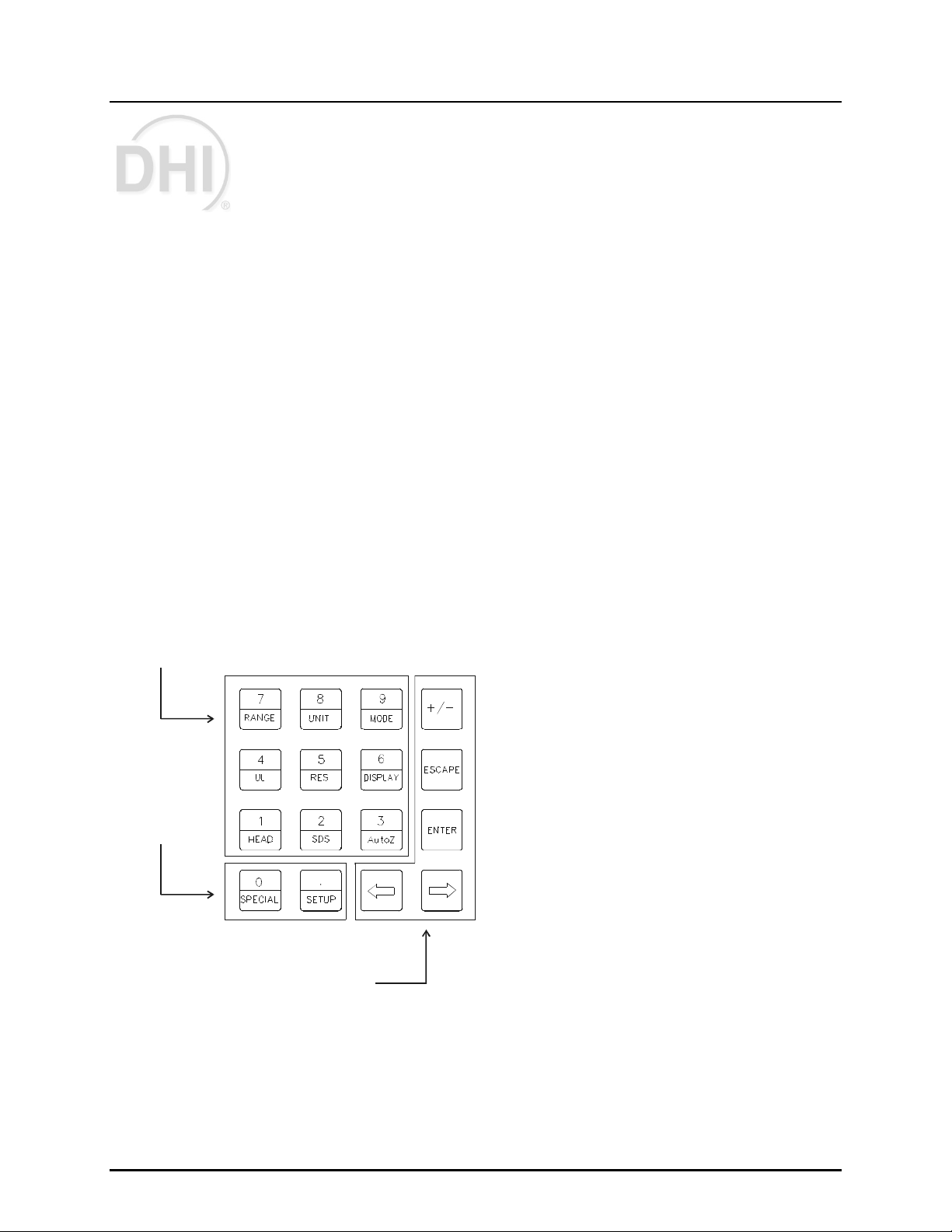
3.1.1 KEYPAD LAYOUT AND PROTOCOL
The RPM3 has a 4 x 4 keypad and an [ENTER] foot switc h for loc al operator access to dir ect
functions, function menus and for data entry.
3
1. The Editing and Execution keys are for
execution, suspending execution, backing up
in menus and editing entries.
The Menu/Data keys provide access to
2.
function menus from the main run screen.
The menu name is on the bottom half of
the key. The SETUP menu is for more
frequently used functions (see Section 3.3).
2
1
The SPECIAL menu is for functions that are
NOT generally used as a part of day to day
operation (see Section 3.4). These keys enter
numerical values when editing.
The Function/Data keys allow very
3.
commonly used functions to be accessed
directly from the main run screen by a single
keystroke. The name of the function is on the
bottom half of the key (see Section 3.2.1).
These keys enter numerical values when
editing.
[ENTER] Foot Switch (not shown) acts in exactly the same manner as t he keypad [ENTER]
4.
key. It serves as a remot e [ENTER] key to be used when the operat or’s hands are occupied or
touching the RPM3 front panel is not convenient.
Figure 6. RPM3 Keypad
Page 15 ©2000 DH Instruments, Inc.
Page 26
RPM3/HPMS A30000/ A6000- AF Operation and Mai ntenance Man ual
Key press confirmation is provided by both tactile and audible feedback. A single tone
confirms a valid entry, a descending t wo note t one signals an invalid ent ry. The audible v alid
entry feedback can be suppressed or modified by pressing [SPECIAL] and selecting
<7Intern>, <2sound> (see S ection 3.4.7.2) .
Pressing the [ENTER] key or foot swit ch generally c auses exec ution or f orwar d movement in
the menu tree.
Pressing the [ESCAPE] key moves back in the menu tree and/or causes execution to c ease
or suspend without changes being implemented. Pressing [ESCAPE] repeatedly event ually
returns to the main run screen. From the main run screen, pressing [ESCAPE] allows
momentary viewing of the RPM3 introduction screen.
Pressing the [+/ -] key changes a numerical sign when editing. It also toggles through
multiple screens when available.
Pressing the [
←←←←] and [→→→→] keys allow reverse and forward cursor movement when editing
data entry. These keys are also used to scroll through choic es .
Some screens go beyond the two lines provided by the display. This is ind icated b y a flashing
arrow in the second line of the displa y. Use [←←←←] and [→→→→] to mo ve the cursor to access the
lines that are NOT visible or directly enter the number of the hidden menu choice if yo u know
it.
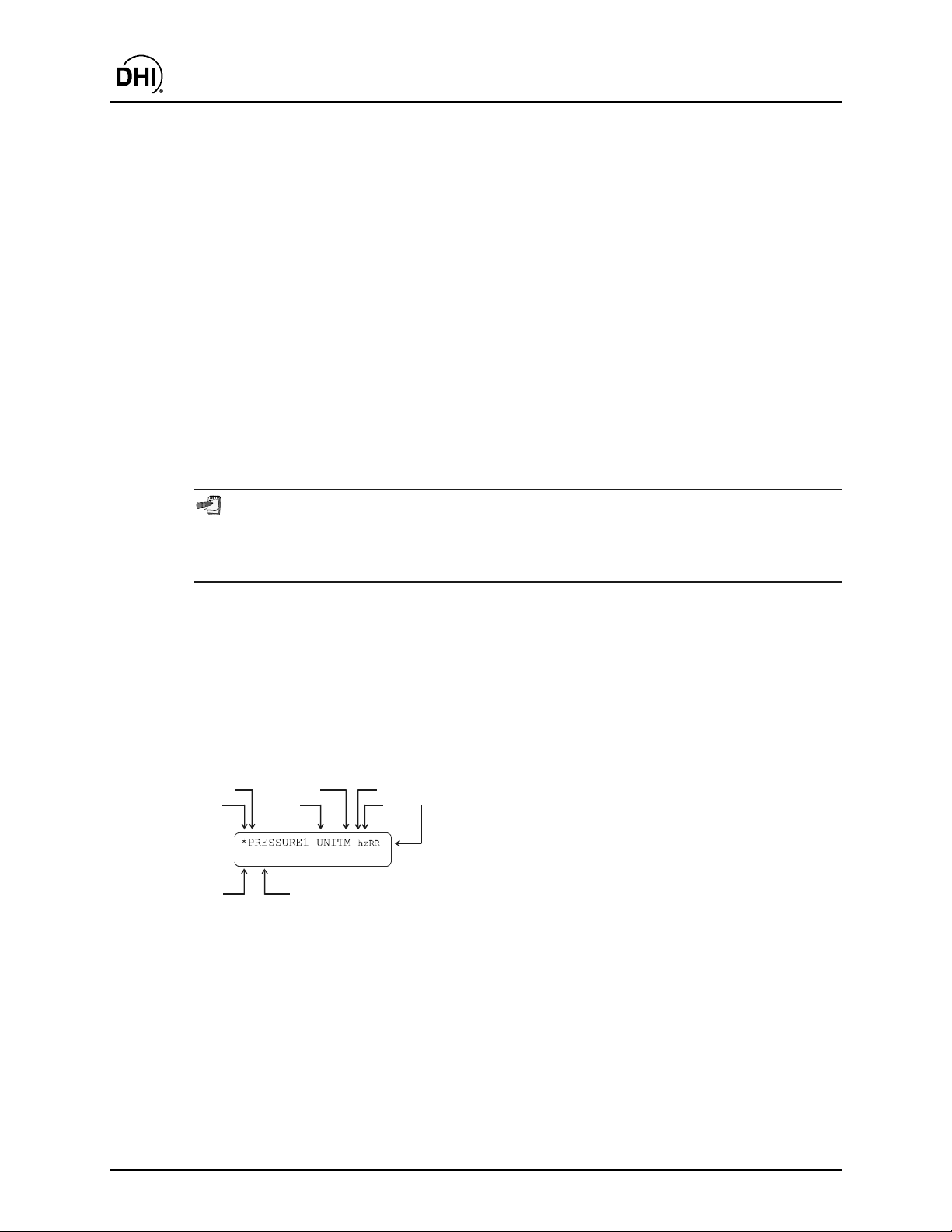
3.1.2 MAIN RUN SCREEN
The RPM3 main run scr een is its home display that is reac hed on power up and from which
other functions and menus are accessed. It is the top level of all menu struct ur es .
The main run screen is where the RPM3 is left in normal operation. It display s the current
measured pressure as well as a v ar iety of additional information if desired.
2
1
D DISPLAY FUNCTION
9
4. <M>: Pressure measurement mode: <g> for gauge, <a> for absolute (see Section 3.2.4).
5. <h>: Indicates whether a head correction is applied. <h> if applied, blank if NOT (see Section 3.2.8).
6. <z>: Indicates whether the autozero function is ON or OFF. <z> if ON; blank if OFF (see Section 3.4.1).
7. <RR>: Indicates active RPT (<H> = high, <L> = low) and range (<1> = low, <2> = mid, <3> = hi) (see
Section 3.2.2).
8. <DISPLAY FUNCTION>: Information displayed depends on current display function.
9. <D>: Indication of w hat is being displayed on the bottom line of the display as set by the DISP LAY func tion (see
Section 3.2.7). Choices include:
• <σσσσ>: Current DISPLAY mode is average (see Section 3.2.7.1).
• <R>: Current DI SPLA Y mode is rate (s ee Sec tion 3. 2.7.2); or if <n avg > is in the bottom r ight hand c or ner of
the display, c urrent DISPLAY mode is average and this is the instantaneous reading average screen (s ee
Section 3.2.7.1).
• <H>: Current DISPLAY mode is hi/lo (see Section 3.2.7.5).
4
3
8
5
7
6
1. <•> Ready/Not Ready indication, <•> when Ready,
↑↑↑↑> or <↓↓↓↓> indicating direction of measur ed pressure
<
evolution when Not Ready (see Section 3.1.5).
2. <PRESSURE1>: Numerical value and sign of
pressure meas ur ed by ac tiv e R PT and r ange. S hows
result of last average in average display
mode (see Section 3.2.7.1).
3. <UNIT>: Current unit of measure (see Section 3.2.3).
©2000 DH Instruments, Inc. Page 16
Page 27

RPM3/HPMS A30000/ A6000- AF Operation and Mai ntenance Man ual
• <D>: Current DISPLAY mode is deviation (see Section 3.2.7.3).
• <✳✳✳✳>, <↑↑↑↑> or <↓↓↓↓>: Current DISPLAY mode is RPT (see Section 3.2.7.4).
• <F>: Current DISPLAY mode is freeze (see Section 3.2.7.6).
• Blank, NO character: Current DISPLAY mode is clean (see Section 3.2.7.7).
RPM3 has a screen saver function that causes the display to dim if NO key is pressed for
10 minutes. Pressing a key restores full power to the display. The screen saver activation
time can be changed or screen sa ving can be co m pletely suppressed (see Sectio n 3.4.7.1).
3.1.3 SOUNDS
RPM3 is equipped with a variable frequency tone device to provide audible feedback
and alarms. The beeper is us ed for the following indications :
• Valid key press: Brief beep. Choice between three frequencies or NO sound is
available (see Section 3. 4.7.2).
• Invalid key press or out of tolerance reading when running an automated
test sequence: Descending two tone blurp (see Section 3.2.11.2).
• In tolerance reading when running an automated test sequence: Ascending three
tone fanfare (see Section 3.2.11.2).
• Leak check rout ine compl et ed: Three two sec ond beeps ( s ee S ec tion 3.3.5).
• UL (upper limit) exceeded: Intermittent one s ec ond beeps (see Section 3.2.5).
• Pmax! (overpressure limit) exceeded: Eight second high frequency beep (see
Section 3.2.5.1).
• Lo RPT is active but a Hi RPT range is selected: Intermittent two second high
frequency beep. T he audible alarm is combined wit h flashing of t he red, Lo RPT Active
LED on the HPMS (see Section 3.2.5. 2) .
3.1.4 SOFT [ON/OFF] KEY
RPM3 is equipped with a soft [ON/OFF] key and indicator LED on the bottom left hand
corner of the front panel. The purpose of the soft ON/OFF key is to put RPM3 into a
dormant mode in which the dis play is turned OFF but power is still s upplied and overpres s ur e
functions are still active. When RPM3 is ON, the ON/OFF indicator is ON continuously.
When RPM3 is soft OFF, the ON/OFF indicator blinks ever y five seconds.
The soft [ON/OFF] key can also be used to reset from an overpressure condition (see
Section 3.2.5.1).
When RPM3 is soft OFF, r ec eiv ing a r em ote command turns it ON.
Page 17 ©2000 DH Instruments, Inc.
Page 28

RPM3/HPMS A30000/ A6000- AF Operation and Mai ntenance Man ual
3.1.5 PRESSURE READY <*>/NOT READY (<↑↑↑↑> OR <↓↓↓↓>) INDICATION
The character to the left of the measured pressure on the main run screen provides a
pressure Ready <*>/Not Ready (<
provide the user with a clear and objective indication of when a stable pressure has
been achieved. Ready <*> is indicated when the current stability (rate of change) of
pressure is less t han the stability limit. The user can set the stability limit (see Section 3.3.4) .
The Ready indicat ion is often used when c omparing the RPM3 and a t est dev ice to indicate
when a valid reading can be made.
↓↓↓↓> or <↑↑↑↑>) indication. This indication is intended to
Ready <*>/Not Ready (<
• <*>: Pressure Ready (stable).
• <↓↓↓↓>: Pressure Not Ready (unstable) and dec r eas ing.
• <↑↑↑↑>: Pressure Not Ready (unstable) and inc r eas ing.
↓↓↓↓> or <↑↑↑↑>) character indications are:
3.1.6 MULTIPLE PRESSURE RANGES
RPM3 A30000/A6000-AF has t wo ref erence pres sure t ransducer s (RP Ts) eac h of which has
three ranges for a total of six pressure ranges. This multi-ranging feature allows
measurement uncertaint y to be optimized for the range of pressur e in which you ar e working.
Generally, the bes t range to select ( see Section 3.2.2) is that whose full scale is closest t o,
but greater than, the maximum pressure of the device or system under test.
RPM3 handles all of the dat a operat ions needed to mak e r ange c hanges occur t ranspar ently
to the user when the RA NGE f unct ion is used f or range s election. For a range change t o be
executed, the current pressur e applied to the RPT on which the r ange is being select ed must
be lower than the current upper limit (UL) of that range (see Section 3.2.5). The RPM3
Sequence feature automatically selects the most appropriate range based on the range of
the device under test (see Section 3. 2.11).
When the range is changed, the upper limit automatically changes to the default for that
range or to the last upper limit set for that range. In addition, most other functions and
settings are range specific (see Section 3.2.2).
RPM3 A30000/A6 000- AF ha s s ix ranges. In general, s ettings and operationa l adjustments
are specific to the range currently in use, as if you had six instruments rather than one.
The DISP LAY function, HEAD functions and AUTO RE ADRT function are NOT range specific.
In remote mode, m ost settings are RPT specific rather than range specific (see Section 4.3 ).
©2000 DH Instruments, Inc. Page 18
Page 29
RPM3/HPMS A30000/ A6000- AF Operation and Mai ntenance Man ual
3.1.6.1 RANGES AND IDENTIFICATION
The active RPT and range is cont inuously indic ated in t he upper right hand cor ner of
the main run screen and m os t other screens.
Hi RPT: The A30000 RPT whose maximum range is 30 000 psi (200 MPa) is
referred to as the Hi RPT.
Lo RPT: The A6000 RPT whose maximum r ange is 6 000 psi (40 MPa) is referred
to as the Lo RPT.
Range 1, 2 or 3: The three ranges of each RPT are r eferred to as 1 = lo range,
2 = mid range, 3 = hi range. The Lo RPT ranges, low to high, are L1, L2, L3.
The high PRT ranges, low to high, are H1, H2, H3.
Table 2. RPM3 Range Identification Summar y
REFERENCE PRESSURE
TRANSDUCER AND RANGE DESIGNATION DISPLAY SYMBOL *
Lo RPT, Lo range Lo, 1 L1 2 000 ( 14)
Lo RPT, Mid range Lo, 2 L2 4 000 (28)
Lo RPT, Hi range Lo, 3 L3 6 000 ( 42)
Hi RPT, Lo range Hi, 1 H1 10 000 (70)
Hi RPT, Mid range Hi, 2 H2 18 000 (125)
Hi RPT, Hi range Hi, 3 H3 30 000 (200)
* The display symbol is included in the upper, right hand corner of most RPM3 menu displays as
a convenient indicator of active range.
RANGE
PSI (MPa)
3.1.7 AUTOMATED TEST/CALIBRATION SEQUENCES
The RPM3 SEQUE NCE function supports “quick” and “file” automated calibrati on sequences.
These automatically set the appropriate RPM3 range, resolution and stability limit based on
the characteristics of the device under test. They also prompt the user through the
increments of the calibration sequence and log calibrat ion data. The SEQUENCE funct ion
should be used for most common calibration tasks, especially calibration of analog pressure
gauges (see Section 3. 2.11).
Page 19 ©2000 DH Instruments, Inc.
Page 30

RPM3/HPMS A30000/ A6000- AF Operation and Mai ntenance Man ual
3.1.8 HPMS (HIGH PRESSURE MOUNTING SYSTEM)
The HPMS (high pressure mount ing system) holds the RPM3 at a convenient viewing angle
and includes a valve and visual indicat ors to isolate and prot ect the RPM3’s 6 000 psi RPT
(Ranges L1, L2, L3) when us ing the 30 000 psi RPT (Ranges H1, H2, H3).
m
m OPERATION
mm
Numerical references in this Section ref er to Figure 1.
In normal use, t he operator’s only interaction wit h the HPMS is t o operate the isolation
valve knob to connect and disconnect the Lo RPT from the TEST port. The valve’s
operation is prompt ed by the Valve Posit ion LEDs ( 1, 3).
The Lo RPT isolation valve (2) isolates and protects t he Lo RPT from the TES T port
when it is closed (knob f ully CCW) and opens the Lo RPT to the T EST port when it is
open (knob fully CW).
The Valve Position LEDs (1, 3) indicate the position in which the valve knob s hould be
set based on the current range selection on t he RP M 3. If a range on the Hi RPT (H1, H2
or H3) is selected, the LO RPT SHUT OFF LED (1) is lit indicating that t he valve knob
should be turned fully CW to close t he valve, prot ecting the Lo RPT from high pressur e.
If a range on the Lo RPT (L1, L2 or L3) is selected, t he LO RPT ACTIVE LE D (3) is lit
indicating that the valve knob should be turned fully CCW to open t he valve, connect ing
the Lo RPT to t he test pressure.
The HPMS isolatio n va lve (2) must always b e in the clo s ed position (knob fully CCW) when
operating a t p re ss ure grea te r tha n 6 000 psi (40 MPa ).
The CAUTIO N LO RPT ACTIVE LED (4) is used to indicate t hat the Lo RPT is active
and provide a warning when the Lo RPT is active but a Hi RPT range is selected on
the RPM3.
The CAUTION LO RPT ACTIVE LED (4) is driven by the value of pressure currently
measured by the Lo RPT, it is not driven by the valve posit ion as there is no sensing of
the valve position.
The CAUTION LO RPT ACT IVE LED (4) has three possible conditions:
• LED is OFF: The Lo RPT is NOT act ive. The Lo RP T is considered ac tive when it
measures a pressur e gr eater than 30 psig (200 kPa) .
• LED ON continuously: The Lo RPT IS active and a Lo RPT range is selected on
the RPM3. The LED is lit as a reminder that the Lo RPT is act ive and press ure over
its maximum wor k ing pr es s ur e of 6 600 (46 MPa) should not be applied.
• LED is flashing on accompanied by high frequency beeps and <!!!LO RPT
ACTIVE!!!> disp layed by RPM3: Lo RPT IS ac tive and a Hi RP T range is s elected
on RPM3. The Lo RPT should NOT be active when a Hi RPT range is in use.
Hi RPT ranges will overpres s ur e and dam age the Lo RPT.
©2000 DH Instruments, Inc. Page 20
Page 31
RPM3/HPMS A30000/ A6000- AF Operation and Mai ntenance Man ual
If a Hi RPT range is selected w ith the Lo RPT active, RP M3 go es into an alarm condition
to avoid accidental overpressure of the Lo RPT while using a Hi RP T range. The pressure
on the Lo RPT must be reduced to less than 30 psig (200 kPa) so that the CAUTION LO
RPT ACTIVE LE D is O FF b efore shutting the L o RP T is olatio n valve and selecting a Hi RPT
range.
The pressure rel ief valve (6) is set to open at 110 % of the RPM3 range L3 ( 46 Mpa;
6 600 psi). When the pr essure applied to the Lo RPT reaches approximately 6 600 psi
(46 MP a), the pressure relief valve (6) will open reducing pressur e and bleeding oil into
the pressure relief run off cup (7). Prior to opening the pr essure relief valve, the RPM3
will have gone into an overpressure condition (see Sect ion 3.2.5.1). If an overpressure
condition occurs, reduce pressure as soon as possible. The pressure relief valve will
reseat automatically when pressure is reduc ed.
Do NOT overpressure the Lo RPT. The Lo RPT may be da m aged beyond repair by pressure
greater than 6 600 psi (4 6 MPa ). RPT dam age from o verpress ure is lo gged in user and
factory maintenance pages and is not covered by the product warranty. The HPMS
pressure relief valve should only be considered a last resort means of protecting the
Lo RPT. Following proper operating procedures, the Lo RPT should never be
7
6
5
34
overpressured.
1. Lo RPT Pressure Relief Valve (not shown) 5. Lo RPT Active Valve Position LED
2. Lo RPT Relief Oil Run-Off Cup (not shown) 6. Caution Lo RPT Active LED
3. Lo RPT Shut OFF Valve Position LED 7. RPM3 Reference Pressure Monitor
4. Lo RPT Isolation Valve
1
2
Figure 7. RPM3/HPMS Front Panel
Page 21 ©2000 DH Instruments, Inc.
Page 32

RPM3/HPMS A30000/ A6000- AF Operation and Mai ntenance Man ual
1
7
6
2
3
4
5
1. HPMS TEST port (DH500 F) 5. Lo RPT Isolation Valve
2. Connection to RPM3 Hi RPT (A30000) 6. RPM3 Reference Pressure Monitor
3. Lo RPT Pressure Relief Valve (6 600 psi) 7. Connection to RPM3 Lo RPT (A6000)
4. Pressure Relief Valve Oil Run Off Cup
Figure 8. RPM3/HPMS Internal Schematic
3.2 DIRECT FUNCTION KEYS
3.2.1 DIRECT FUNCTION KEYS SUMMARY
Local operation of RPM3 is through the 4 x 4 pressure sensitive k eypad and an [ENTER]
foot switch. To minimize the us e of multi-layered menu s tructure, the 4 x 4 keypad numerical
keys also provide direct access to the most commonly used functions. The function
accessed is labeled on the bottom half of the k eys. Direct func tion key s are act ive whenever
RPM3 is in its main run screen. Table 3 summarizes the operation of the direct function
keys.
Table 3 provides a brief summary of direct function key operation. It may be useful to keep a
copy of this summary near the RPM3/HPMS, especially when first becoming acquainted with
its operatio n.
©2000 DH Instruments, Inc. Page 22
Page 33

RPM3/HPMS A30000/ A6000- AF Operation and Mai ntenance Man ual
Table 3. Summary of RPM3
Direct Funct ion K ey Operation
Direct Function Keys are active from the MAIN run screen
See corresponding manual secti ons for fu ll detail .
.
SETUP
0
SPECIAL
1
HEAD
2
SDS
3
AutoZ
4
UL
5
RES
Menu of commonly used setup features including run LEAK CHECK.
Menu of less frequently used internal func tions and settings.
Set fluid head height.
SDS function is not used on RPM3 A30000/A6000- A F.
Runs AutoZ to rezero active range. In gauge mode, should only be used
after assuring the system is vent ed and waiting two minutes.
View/adjust upper pres s ur e lim it alarm.
Adjust display resolution of measured press ur e and other indications and
settings.
6
DISPLAY
7
RANGE
8
UNIT
9
MODE
10
ENTER
Select [DISPLAY] function for sec ond line of RPM3 display. Choices
include <average>, <rate>, <other RP T>, <Hi /Lo>, <Deviation>,
<Freeze>, <Clean>.
View/Select ranges . Shows active range and then toggles through
available ranges. Pressing [ENTER] on a range activates it.
Change pressure measurem ent unit. Choice of unit s c an be c us tomized.
Change pressure measurem ent mode (<gauge>, <absolute>).
ENTER data and/or run automated tes t/calibration sequenc e from MAIN
RUN screen.
Page 23 ©2000 DH Instruments, Inc.
Page 34

3.2.2 [RANGE]
m
m PURPOSE
mm
To view and/or change the active pressure m eas urement range.
m
m PRINCIPLE
mm
RPM3 A30000/A6000 has six ranges (see Section 3. 1.6).
The [RANGE] key allows the range values to be viewed and a range selection to
be made.
Most RPM3 settings such as pressure unit of measure (UNIT) and measur ement mode
(MODE), are range specific . Changes made while in one range apply t o that range only
and do NOT affec t the other ranges ( s ee S ec tion 3.2.2).
m
m OPERATION
mm
Pressing [RANGE] activates the range viewing and selecting function.
Pressing [RANGE] again or [+/-] while in the RANGE funct ion steps through display s of
available ranges: Lo to Hi.
RPM3/HPMS A30000/ A6000- AF Operation and Mai ntenance Man ual
When [RANGE] is first pressed, the active reference pressure transducer (RPT) and
range are displayed:
2
1
psi 30000g/30000a
5
4
3
1. Identifies active RPT (Lo or Hi).
Identifies active range (1, 2 or 3) of t he act ive RPT.
2.
Range designator.
3.
Full scale pressure value in the current units for the
4.
RPT and range when used in gauge (g) or absolute
(a) mode.
Pressure unit of measure (the unit of measure
5.
currently active for t his range) .
©2000 DH Instruments, Inc. Page 24
Page 35

RPM3/HPMS A30000/ A6000- AF Operation and Mai ntenance Man ual
Pressing [RANGE] again or [+/-] causes t he screen to step through t he other available
ranges in sequence Lo to Hi:
2
1
psi 6000g/6000a
5
4
3
1. Identifies RPT (Lo or Hi).
Identifies range of the RPT (1, 2 or 3) .
2.
Range designator.
3.
Full scale pressure value in the active units of
4.
measure for the RPT and range number when used
in gauge (g) or absolute (a) mode.
Units of measure (the unit of measure currently
5.
active for the range).
Range full scale limits are given in the pressure unit that is currently active for that
range.
Pressing [ENTER] while in the RANGE f unction causes the RPM 3 to attempt to change
the active range t o the range currently displayed. The pressur e currently applied to the
RPT with the new range m ust be lower than upper limit (UL) of t he new range for t he
range change to be completed (see Section 3.2. 5) .
Any time a range change causes the active RPT to change, the HP MS Lo RPT I solation
Valve must be operated to connect or disconnect the Lo RPT from the TEST port.
The green Lo RPT Valve Position LEDs indicate the correct posit ion of t he Lo RPT Valve
Isolation Knob based on t he RP M 3 range currently in use (s ee S ec tion 3.1.8).
Pressing [ESCAPE] while in the range funct ion returns to the main run screen without
changing ranges.
The HPMS Lo RPT Isolation Valve protects the Lo RPT (6 000 psi max) from
overpressure when the Hi RPT is in use. Familiarize yourself w ith HPMS operation (s ee
Section 3.1.8) before changing ranges and applying pressures. Always turn the Lo RPT
Isolation Va lve fully in the directio n o f the lighted green L E D before app lying p res s ure.
For a range change to occur, the pressure currently measured by the new range RPT
must be less than the current up per limit (see Section 3.2.5) of the new ra nge. If this
condition is N OT m et w hen a ra nge cha nge is attem p ted , a wa rning message is disp la yed
and the range change is NOT co mpleted. Reduce the pressure app lied to the T EST p ort
and reattempt the range change.
Running an automated test SEQUE NCE may change the ac tive range. The SEQUEN CE
function autom a tica lly s ets the a ctive ra nge to the m o s t approp ria te ra nge based on full
scale of the device under test (see Section 3.2.11).
Page 25 ©2000 DH Instruments, Inc.
Page 36

RPM3/HPMS A30000/ A6000- AF Operation and Mai ntenance Man ual
Range Specific Functions and Settings
In general, RPM3 functions and sett ings ar e r ange s pec ific. They are s et and stored f or each
range so that changing settings when in one range does NOT change settings in the
other ranges. When returning to a range, settings are the same as they were when the
range was left.
Functions and set tings that are NO T range specific are:
• Functions: HEAD (see Section 3.2.8), DISPLAY (see S ec tion 3.2.7).
• Setup Menu: <3ReadRt> (see Section 3. 3.3).
Running an automated test SEQUENCE may change the active range and the UNIT,
STABILITY and RESOLUTION settings for the range. The SEQUENCE function
automatically sets these parameters to the most appropriate values based on the
characteristics of device under test (see Section 3.2.11).
In remote mode, most settings are RPT specific rather than range specific (see
Section 4.3 ).
3.2.3 [UNIT]
m
m PURPOSE
mm
To specify t he pr es sure unit of measure for the active r ange.
See also Section 3.2.4.
m
m PRINCIPLE
mm
RPM3 allows the pressure measurement unit for a range to be changed.
Internally, RPM3 always operates in Pascal (Pa), the SI unit of pressure. Values of
pressure are repres ented in other units by t he applic ation of conversion f ac tors to c onv er t
from Pa (see S ec tion 7.1).
The pressure measurement unit selection (e.g., psi, kPa, etc.) is separate from the
pressure measurement mode selection (gauge or absolute). See Section 3.2.4 for
information on changing the measurement mode.
©2000 DH Instruments, Inc. Page 26
Page 37

RPM3/HPMS A30000/ A6000- AF Operation and Mai ntenance Man ual
m
m OPERATION
mm
To change the pressure measurement unit for the
active range, press the [UNIT] function key.
The display is:
The cursor is on the number corresponding to the active unit for the active range.
The active range is indic ated in the upper right hand cor ner . To change the pressur e unit
for the active range, select the desired unit. The display returns to the main run screen
with the selected unit active.
The pressure measurement unit selected is range specific. When in a given range, all
functions and settings are represented in the current measurement unit for that range.
However, c erta i n interna l and/or metro logical functions (e.g., RPT ca lib ration coe fficie nts )
are always represented in Pa rega rd less o f the active range unit.
See Section 7.1 for tables of the conversion factors used b y RP M 3 .
The UNIT function provides rapid access to a choice o f six units. The choice o f units can
be customized by the user from a wider selection (see Section 3.3.2 ). To return the six
units of the UNIT function key to defa ult, see Section 3.4.5 . 2.
4bar
3.2.4 [MODE]
m
m PURPOSE
mm
To set the meas urement mode (gauge or absolut e) for the activ e r ange.
See also Section 3.2.3.
m
m PRINCIPLE
mm
The RPM3 A30000/A6000 RP Ts have an evacuated and sealed ref erence so that they
always measure absolute pr essure. RPM3 suppor ts extensive on-boar d measurement s
and logic to precisely subtrac t at mospher ic press ure fr om absolut e press ure when gauge
pressure measurements are desired. A separate on-board barometer and unique
atmospheric compensation system are used to assure highly accurate gauge pressure
values are provided even if atmospheric pressur e c hanges between zer oing opportunities
(see Section 3.4.1, Gauge Mode with an Absolute RPT, Dynamic Compensation for
Atmospheric Pressure). This allows simple, one step switching between gauge and
absolute measurement modes without special pr oc edur es or hardware.
Page 27 ©2000 DH Instruments, Inc.
Page 38

RPM3/HPMS A30000/ A6000- AF Operation and Mai ntenance Man ual
m
m OPERATION
mm
To change the pressure meas urement mode for t he
active range, pr es s [MODE]. The display is:
The cursor is on the number corresponding to the current m eas ur ement mode. Making a
measurement mode selection returns to the main run screen with the selected
mode active.
When going from absolute to gauge measurement mo de, the AutoZ function should be
used to update the atmosp heric p ress ure offset (see Sections 3.2.10, 3.4. 1).
3.2.5 [UL] (UPPER LI MIT)
m
m PURPOSE
mm
To set the upper pressure limit value f or the active range and measur em ent mode.
m
m PRINCIPLE
mm
1absolute 2gauge
The UPPER LIMIT function provides the user with a settable pressure limit at which an
alarm will sound.
When the upper limit is r eac hed the RPM3’s beeper sounds inter m ittently.
The UPPER LIMIT function has two purposes. First, when UL is set t o its default value,
it serves as a warning that the maximum pressure of the active range is about to
be exceeded. Second, UL can be set by the us er to a lower value t han the default value
to provide an alarm that a specific pressure limit has been exceeded. This feature is
often used to help protect an external device or system to which RPM3 is connected.
For example, UL might be set just over t he full sc ale of a device under tes t (DUT ) that is
being calibrated. The UPPER limit is set automatically by the SEQUENCE function when
a sequence is run to protect the device under test from overpressure (see Section
3.2.11).
Upper limit settings are specific to each range and measurement mode (gauge
or absolute).
The UL function is separate and different from the over-pressure (Pmax!) function.
The Pma x! function is NOT adjustable a nd activates regardless o f UL setting when the
maximum acceptable pressure for the active RPT range has been exceeded (see
Section 3.2 .5.1).
.
©2000 DH Instruments, Inc. Page 28
Page 39

RPM3/HPMS A30000/ A6000- AF Operation and Mai ntenance Man ual
m
m OPERATION
mm
When [UL] is pressed from the main run sc reen the display is:
1. Edit field to view current upper limit value and modif y
30600 psi g
1
if desired. The value is always in the current unit of
measure.
Enter the desired upper limit value and RPM3 returns t o the main run screen with the
new upper limit value activ e.
When the upper limit has been exceeded, the display of cur rent pr essure f lashes and t he
beeper sounds at two second intervals. Reduce the pressure applied to the RPT to
lower than the upper limit to return to norm al oper ation.
Default upper limit values are 105 % of the range full scale for ranges 1 and 2 and 102 %
FS for range 3. Upper lim it values m a y be ad justed b y the user. The a djusted value must
be lower than or equal to the default value and higher than the current measured
pressure.
Upper limit values are specific to ea ch range AND measurement mode. Do NOT assume
that the upper limit se t in o ne m ea s urem ent mode will ap p ly to the other. Fo r example, if
you set 3 000 ps i as the upper lim it in ga uge m o d e , the up per limit will NOT b e 3 000 psi
in absolute m ode. The up per limit setting in o ne mode has NO affect on the up per lim it
setting in another m o d e .
[RANGE] is disabled so ra nge changes ca nnot b e m a de w hen the upper lim it is ex ceed ed .
Running an automa te d te s t SE QUENCE with the SE QUENCE function a utomatically sets
the UPPER LIMIT bas ed on the full scale of the device under te st. I t may b e neces sa ry to
readjust the UPP ER LIMIT a fter running a SEQUENC E (see Section 3.2.11).
Page 29 ©2000 DH Instruments, Inc.
Page 40

RPM3/HPMS A30000/ A6000- AF Operation and Mai ntenance Man ual
3.2.5.1 OVER-PRESSURE FUNCTION (<PMAX!>)
m
m PRINCIPLE
mm
In addition to the UL (Upper Limit) function, RPM3 has an over-pressure
function (Pmax!). Whereas the UL function is a settable alarm to assist the
operator in monitoring a pressure limit, Pmax! is a fixed limit intended as a
warning that the max imum pressure accept able for a range has been exceeded
and damage to the RPM3 may be imminent. The Pmax ! f unction ac tivat es when
the maximum acceptable pressure for the c urrent range on t he active or inac tive
RPT has been exceeded.
m
m OPERATION
mm
When the overpres s ur e function activates because Pmax! has been ex c eeded:
• The beeper sounds continuously at high frequency for 8 seconds.
<Rng “RR” RPT EXCEEDED PMAX> and overpressure value display
toggles with normal run screen ( RR identifies the range that has exc eeded
Pmax! (e.g., L1, H3).
• <!!!Pmax!!!> displays in the main run screen instead of the measured
pressure so long as the pressure read by the active RPT exceeds P m ax !.
• The [RANGE] key is disabled.
• The overpressur e c ondition is logged.
To recover from an overpressure c ondition, remov e the over pressur e source and
then clear the overpressure condition by cycling RPM3 power using the soft
[ON/OFF] key (see Section 3.1.4) or by disconnecting and reconnecting the
power cable. The overpressure message will continue to display until the
overpressure condition has been cleared by cycling power.
The overpressure function monitors both the active a nd inactive RPT. When a n
overpressure occurs, check the <Rng “RR” RPT exceeded> message to determine
which RPT and range has been overpressured.
Pmax! values are 110 % of the range full scale for ranges 1 and 2 and 104 % of the
range full scale for range 3.
When Pmax! is exceeded, <!!!Pmax!!!> displays on the RPM3 display top line
where the current pressure is normally displayed because the actual pressure
applied can NO longer be indicated relia b ly.
©2000 DH Instruments, Inc. Page 30
Page 41

RPM3/HPMS A30000/ A6000- AF Operation and Mai ntenance Man ual
3.2.5.2 LO RPT PROTECTION (<!!LO RPT ACTIVE!!>)
m
m PRINCIPLE
mm
RPM3/HPMS A30000/A6000-AF has a special warning system to reduce the risk
of overpressure to the Lo RPT. The warning system int errupts operat ion when a
range on the Hi RPT is selected but the Lo RPT appears to be active (i.e.,
connected to the t est port). Since all the Hi RPT ranges include pressures that
are high enough to overpressure and damage t he Lo RPT, if a Hi RPT range is
selected, the Lo RP T should be shut off from t he TEST port by the HPMS Lo
RPT Isolation V alv e.
If the RPM3 Lo RPT measures a pressure greater than 30 ps ig (200 kPa) AND a
Hi RPT range (H1, H2, H3) is currently selected, t he Lo RPT is assumed to be
active (connect ed to the TEST por t). If the Lo RPT is active and a HI RP T range
is selected, the Lo RPT Active warning system activates. The Lo RPT Active
warning system prevents further operation until pressure on the Lo RPT has
been reduced to less than 30 ps ig (200 kPa).
m
m OPERATION
mm
If the Lo RPT is ac tive and a range of the Hi RPT (H1, H2, H3) is selec ted:
• The RPM3 displays <!!LO RPT ACTIVE!!> and sounds two second
intermittent beeps.
• The red, Lo RPT A c tive WARNING LE D on the HPMS front panel flashes.
To cancel the warning condition, reduce pressure on the Lo RPT to less than
30 psig (200 kPa). Operation returns to normal.
See Section 3.1. 8.
The Lo RPT Active Warning may occur when the HPMS Lo RPT Isolation Valve
is closed. If this o ccurs , there may be a leak thro ugh the Is o la tio n V a lve.
3.2.6 [RES] (RESOLUTION)
m
m PURPOSE
mm
To set the res olution with which measured pressures and other indic ations and s ettings
are displayed.
Page 31 ©2000 DH Instruments, Inc.
Page 42

RPM3/HPMS A30000/ A6000- AF Operation and Mai ntenance Man ual
m
m PRINCIPLE
mm
The resolution with which the pressure meas ured by RPM 3 is displayed c an be adjusted.
This feature c an be used to reduce the resolution when lower precision measurem ents
are being made and additional digits m ight confuse or distr ac t the operator.
The resolution setting det ermines the number of digits with which press ure is displayed.
The desired resolution is calculated based on the full scale of the range and then
rounded down to the nearest digit. For example, resolution of 0.01 % on a range of
18 000 psi is 18 000 x 0.01 % = 1.8 which is rounded down to 1 psi.
The default resolution setting is 0.001 % for each range. The maximum resolution
setting is 0.0001 %.
m
m OPERATION
mm
To access the resolution function, press [RES].
The display is:
Use the [
←←←←] and [→→→→] keys to select the desired level of resolution. Press [ENTER] to set
the resolution and return to the main run sc reen.
The resolution setting affects the display of the measured pressure as well as other
indications and settings, such as quantities shown by DISPLAY functions (see
Section 3.2. 7), the reading of the on-b oard barom e ter, etc.
The resolution setting is range specific. A resolution setting made in one range does
NOT affect other ranges.
Running an automa te d te s t SE QUENCE with the SE QUENCE function a utomatically sets
the RESOLUTION to the most appropriate value based on the characteristics of the
device under test. It may be necessary to readjust the RESOLUTION after running a
SEQUEN CE (see Sectio n 3 . 2.11).
©2000 DH Instruments, Inc. Page 32
Page 43

RPM3/HPMS A30000/ A6000- AF Operation and Mai ntenance Man ual
3.2.7 [DISPLAY]
m
m PURPOSE
mm
To select, from a variety of c hoices, the inform ation that is displayed on t he second line
of the RPM3 display.
m
m PRINCIPLE
mm
RPM3 supports a variety of advanced pressure measurement functions that are
displayed on the second (bot tom) line of the RPM3 display . In summary, the available
display functions inc luded ar e:
• AVERAGE: Calculates the aver age pressur e measur ed over a user specif ied period
of time and displays the average, the standard deviation about the mean and a
countdown in seconds to the next average (see Section 3.2.7.1). This function is
often used to filter out pressure noise in an unstable system. The magnitude of the
noise is quantified by t he standard deviat ion about the mean. A sec ond Avg screen
allows the instantaneous pressure values to be viewed during an averaging cycle.
• RATE: Calculates and displays the current rate of change of pressure in current
pressure units/ second (see Section 3.2.7.2) . This function is a useful indication of
the stability of the pressure being measured. It is often used as an indication of
positive or negative leak rat e and as a go/NO go crit erion of when t o t ake data when
comparing RPM3 and a device under test , f or exam ple in a calibrat ion. Rat e is us ed
by the Ready <*>/Not Ready (<
condition exists ( s ee S ection 3.1.5).
↑↑↑↑> or <↓↓↓↓>) funct ion to det ermine when a Ready <*>
• DEVIATION: Calculates and displays the difference between the pressure
measured by RPM3 and a target pressure def ined by the user (s ee Section 3.2. 7.3).
This function is useful in monitoring the evolution of pressure around and/or away
from a desired set point.
• RPT: Allows the pressure measured by both the Lo and Hi RPT to be displayed
simultaneously (see Section 3.2.7. 4) .
• HI/LO: Records and displays maximum and minimum pressures measured (see
Section 3.2.7.5). This f unction is used to keep t rack of the minim um and maxim um
pressure observed in a system over a period of time or to monitor whether a
pressure min/m ax lim it has been exceeded.
• FREEZE: Captures and displays the pressure measured by the active range of
RPM3 when the [ENTER] key is pressed (see Section 3.2.7.6). This function is
useful to record the pressure present at the time of an operator observed trigger
event, for example when the needle of an analog gauge was on the nominal point or
when a switch activates.
• CLEAN: Blanks out the second line of the display (see Section 3.2.7.7).
This function is used when a simple display of pressure measured by the RPM3
active range without additional information is des ir ed.
RPM3 also includes a lea k check function (see Section 3.3 . 5).
Page 33 ©2000 DH Instruments, Inc.
Page 44

RPM3/HPMS A30000/ A6000- AF Operation and Mai ntenance Man ual
m
m OPERATION
mm
To set the DI S P LA Y function press [DISPLAY] f r om the main run screen.
The display is:
The cursor is on the active DISPLA Y f unction. Select ing a display f unct ion retur ns to t he
main run screen with the selected funct ion ac tive.
See Sections 3.2.7.1 to 3.2. 7.7 for details on each DI S P LA Y function.
The DISPLAY s election is NOT range specific. A DISP LAY selection ma de in one range
applies to a ll ra nges.
The default DISPLAY function is Rate which causes the second line of the display to
show “R” followed by the current rate of change of pressure in current pressure units
per second.
3.2.7.1 Avg (Average)
m
m PURPOSE
mm
To activate the Average DISPLAY and/or adjust the period of time over which
averaging occurs.
See Section 3.2.7, PRINCIPLE.
m
m OPERATION
mm
To access the Average DISPLAY, press [DISPLAY] and select <1Avg>.
The display is:
1
Edit the averaging time period if des ired. Press ing [ENTER] returns to the main
run screen with the Average DISPLAY ac tive.
1. Edit field for averaging period in seconds.
Default is 20. Minimum 1, maximum 999.
©2000 DH Instruments, Inc. Page 34
Page 45

RPM3/HPMS A30000/ A6000- AF Operation and Mai ntenance Man ual
With the Average DISPLAY act iv e the main run screen is:
1
1. Average measured over last completed
* 5001.6 psi g zH3
σ
0.07 18Avg
averaging period.
Countdown in seconds until completion of
2.
on-going averaging period.
3
2
Standard deviation of last completed
3.
averaging period.
The Average DISPLAY has a second screen that allows the instantaneous
pressure readings to be viewed while an averaging cycle is running.
The instantaneous A v er age screen is:
1
1. Instantaneous pressure values at RPM3s
normal integration rate.
Countdown in seconds until completion of
* 5001.4 psi g zH3
2.
on-going averaging period.
Current rate of change of pressure in
3.
3
2
pressure units/second.
The [+/-] key toggles between the main run Average screen and the
instantaneous values A v er age s c reen.
In the Average DISPLAY the Ready <*>/Not Ready (<↑↑↑↑> or <↓↓↓↓>) indication
applies to the result of the previo us avera ging p eriod . Ready <*> indicates that
all readings during the p revious averaging p eriod met the sta bility criterion (see
Section 3.3.4). Not Ready (<↑↑↑↑> or <↓↓↓↓>) indicates that one or more readings
were outside of the sta b ility criterio n (See Section 3.1.5).
Changing the pressure unit o f meas ure, mea surement m od e (ga uge o r a bso lute)
or range while the averaging sc reen is a c tive, s tarts a new a vera ging p eriod.
Pressing [ENTER] while in the Average DISPLAY aborts the current averaging
period and causes a new one to begin. Pressing [ENTE R] can thus be use to
trigger a new averaging perio d on demand.
To go to a DISPLAY other than Average, press [DISPLAY] and make a new
DISPLAY choice (s ee Sectio n 3 . 2 . 7).
Page 35 ©2000 DH Instruments, Inc.
Page 46

3.2.7.2 Rate
m
m PURPOSE
mm
To activate the Rate DISPLAY.
See Section 3.2.7, PRINCIPLE.
m
m OPERATION
mm
To activate the Rate DISPLAY press [DISPLAY] and select <2Rate>.
Selecting <2Rate> returns to the main run scr een with the Rate DISP LA Y ac tive.
With the Rate DISPLAY activ e the main run screen is:
RPM3/HPMS A30000/ A6000- AF Operation and Mai ntenance Man ual
* 9999.75 psi g zH3
1
1. Current rate of change of pressure in
current pressure units per second.
The Rate DISPLAY is different and sepa rate from the stability setting w hich is
used to set the sta bility criterion on which the Ready <*>/Not Ready (<↑↑↑↑> or
<↓↓↓↓>) indication is b ase d (see Sectio ns 3. 3. 4 and 3 .1. 5). The Ra te D ISPL AY only
causes the current rate of change to be displayed and has NO affect on the
stability setting or the Ready <*>/Not Ready (<↑↑↑↑> or <↓↓↓↓>) condition.
\
To go to a DISPLAY other than Rate, press [DISPLAY] and make a new DISPLAY
choice (see Section 3.2. 7).
3.2.7.3 Dev (Deviation)
m
m PURPOSE
mm
To activate the Deviation DISPLA Y and/or set the deviat ion target value.
See Section 3.2.7, PRINCIPLE.
m
m OPERATION
mm
To activate the Deviation DISPLAY press
[DISPLAY] and select <3Dev>. The
display is:
©2000 DH Instruments, Inc. Page 36
Target:
Page 47

RPM3/HPMS A30000/ A6000- AF Operation and Mai ntenance Man ual
Edit the desired t arget value. Pressing [ENTER] returns to the m ain run screen
with the Deviation DI S P LA Y ac tive using the entered target value.
The target value is the value from which deviations (D) are measured by the
Deviation D ISP LAY following:
D = current pressure - target pressure
With the Deviat ion DISPLAY activ e the main run screen is:
* 9999.85 psi g zH3
Pressing [ENTER] from the main run screen when the Deviation DISPLAY is
active goes directly to the T arget editing s creen. This a llow s the ta rget va lue to
be changed witho ut go ing through the DISPLAY m e nu.
If the pressure measurem ent unit or mod e (gauge or ab solute) is changed while
the Deviation DISP LAY is a ctive the target value remains a t the same num erical
value. It is NOT converted.
To go to a DISPLAY other than Deviation, press [DISPLAY] and make a new
DISPLAY choice (s ee Sectio n 3 . 2 . 7).
3.2.7.4 RPT
m
m PURPOSE
mm
1. Target value.
Deviation of current pressure from the target
2.
12
value.
To activate the RPT DISPLAY.
See Section 3.2.7, PRINCIPLE.
Page 37 ©2000 DH Instruments, Inc.
Page 48

RPM3/HPMS A30000/ A6000- AF Operation and Mai ntenance Man ual
m
m OPERATION
mm
For the sake of clarity, when describing the RPT DISPLAY, the active RPM3 range
when the RPT function is selected is referred to as the “active” range. This is the
range that is displayed on the first line of the display. The other RPT and the
range to be displayed on the second (bottom) line of the RPM3 display are
referred to as the “inactive” RPT and range. It is “inactive” in the sense that all
RPM3 functions and settings such as UNIT and RES still apply to the
“active” RPT. To make changes to the “inactive” RPT, for example to change its
measurement units, it must be made the active RPT by a conventional range
change (see Section 3.2. 2 ).
The RPT display function can only be used effectively when the active range is a
range on the Lo RPT. If the Hi RPT is the active RPT, the “Lo RPT Active Warning”
will interfere as soon as pressure is increased on the Lo RPT (see
Section 3.2.5.2).
To activate the RPT DISPLAY, press [DISPLAY] and select <4RPT>.
The display is:
1
Select Hi RPT range:
1. Lo or Hi - whichever RPT is currently inactive.
Select the desired range of the inactive RP T. M ak ing the range selection returns
to the main run scr een with the RPT DIS P LA Y ac tive.
With the RPT DISPLAY activ e the main run screen is:
1
* 2900.65 psi g zL3
2
1. Active RPT display.
Inactive RPT display.
2.
With the RPT display active, executing a range change to a ra nge on the inactive
RPT causes the range change to occur ma king the inactive RPT the active RPT.
The DISPL AY defaults b a ck to Rate.
To go to a DISPLAY other than RPT, press [DISPLAY ] and make a new DISPLAY
choice (see Section 3.2. 7).
©2000 DH Instruments, Inc. Page 38
Page 49

RPM3/HPMS A30000/ A6000- AF Operation and Mai ntenance Man ual
3.2.7.5 Hi/Lo
m
m PURPOSE
mm
To activate the Hi/Lo DISPLAY.
See Section 3.2.7, PRINCIPLE.
m
m OPERATION
mm
To activate the Hi/Lo DISPLAY press [DISPLAY] and select <5Hi/Lo>.
Selecting <5Hi/Lo> resets the Hi/Lo values and returns to the m ain run screen
with the Hi/Lo DIS P LA Y ac tive.
With the Hi/Lo DISPLAY activ e the main run screen is:
* 8456.95 psi g zL2
2
The Hi/Lo values change each time a new Hi or Lo pressure is obs er v ed.
The Hi/Lo record can be res et at any time by pressing [EN TER]. This allows a
Hi/Lo reset without going bac k through the DISPL AY m e nu.
If the pressure measurem ent unit, mode (gauge o r a b s o lute) o r ra nge is changed
while the Hi/Lo D I SP L AY is active, Hi/Lo resets.
To go to a DISPLAY other than Hi/Lo, press [DISPLAY] and make a new DISPLAY
choice (see Section 3.2. 7).
3.2.7.6 Freeze
m
m PURPOSE
mm
1. Lowest pressure observed since Hi/Lo
reset.
2. Highest pressure observed since Hi/Lo
1
reset.
To activate the Freeze DISP LA Y .
See Section 3.2.7, PRINCIPLE.
Page 39 ©2000 DH Instruments, Inc.
Page 50

RPM3/HPMS A30000/ A6000- AF Operation and Mai ntenance Man ual
m
m OPERATION
mm
To activate the Freeze DISPLAY press [DISPLAY] and select <6Freez>.
Selecting <6Freez> returns to the main run screen with the Freeze
DISPLAY active.
With the Freeze DISPLAY active the main run scr een is :
1. Pressure measured by active range of
* 9999.13 psi g zH3
1
RPM3 when [ENTER] was pressed in the
current pressure units (displays 0.00 by
default when Freeze DISPLAY is first
activated).
Pressing [ENTER] causes the cur rent pressure measured by the active RPM 3
range to be captured and displayed.
If the pressure measurem ent unit, mode (gauge o r a b s o lute) o r ra nge is changed
while the Freeze DISPLAY is active, the Freeze value defaults back to zero .
To go to a DISPLAY other than Freeze, press [DISPLAY] and make a new
DISPLAY choice (s ee Sectio n 3 . 2 . 7).
3.2.7.7 Clean
m
m PURPOSE
mm
To activate the Clean DISPLAY.
See Section 3.2.7 PRINCIPLE.
m
m OPERATION
mm
To activate the Clean DISPLAY press [DISPLAY] and select <7Clean>.
Selecting <7Clean> returns to the main run screen with the Clean
DISPLAY active.
With the Clean DIS P LA Y active the main run s c r een is :
1
* 25486.7 psi g zH3
1. Conventional main run screen first line.
“Clean” second line.
2.
2
To go to a DISPLAY other than Clean, press [DISPLAY] and make a new DISPLAY
choice (see Section 3.2. 7).
©2000 DH Instruments, Inc. Page 40
Page 51

RPM3/HPMS A30000/ A6000- AF Operation and Mai ntenance Man ual
3.2.8 [HEAD]
m
m PURPOSE
mm
To cause a pressure value representing a difference in height to be added to the
pressure measured by the RPM3 reference pr es s ur e transducer (RPT ) .
m
m PRINCIPLE
mm
RPM3’s RPTs measure gauge or absolute pressure at the height of the rear panel
TEST port. F r equent ly, when performing a calibration or test, t he device or system under
test is at a different height than the RPM3’s TEST port. This difference in height,
frequently called head, can cause a significant difference between the pressure
measured by the RPM3 at its TEST por t height and the pressur e actually applied to the
device under test loc ated at a differ ent height. In t his case, it is usef ul to m ake a head
correction to the pressure measured by the RPM3 RPT at its TEST port in order to
accurately predict t he pressur e actually applied at a dif ferent height. T he HEAD f unction
allows head corrections to be applied automatically for a variety of fluids based on
operator entry of the nature of t he pr es s urized fluid and the height dif ference.
RPM3 can accurately determine head pressures f or gas (nitrogen, helium and air) and
liquids (oil, water) as the press urized medium. In calculating the head value, standard
gravity (9.80665 m/s
correcting for temperature of 20°C and the measured pressure using the gas’s
compressibility factor to 1 500 psi (10 MPa) and extrapolated above 1 500 psi.
Above 1 500 psi, gas heads should be minimized to minimize uncertainties due to
head corrections. Oil density is taken at 850 k g/m
at 20°C. Wat er density is t aken at 998.2321 k g/m
also be specified.
2
) is used. Gas densities are calculated from standard density
3
, the density of typical calibration oils
3
(20°C). A custom liquid density may
The [HEAD] funct ion key is used to specify t he difference in height between the RP M3
TEST port and the test . The height units and the head fluid ar e specified by pressing
[SETTINGS] and selecting <1Head> (see Sec tion 3.3.1).
Use of the HEAD function to assure in tolerance measurem ents is particularly critical
when a liquid is the tes t fluid due to the high density of liquids. To determ ine when, and
how precisely, a head correction for liquids m ust be m ade, 0.03 psi/inch (90 P a/cm) m ay
be used as an estimation o f the liquid head value.
Page 41 ©2000 DH Instruments, Inc.
Page 52

RPM3/HPMS A30000/ A6000- AF Operation and Mai ntenance Man ual
Recommended Gauge Mode Head Settin g Procedure i n HGC 30000-AF
When using RPM3 A30000/A6000-AF in an HGC-30000-AF calibrat ion syst em operating
in gauge mode, the recom m ended z er oing and head s etting procedure is as follows:
Vent the syst em by opening the OPG 1 Exhaust Valve. This set s the oil head in the
system at the top of the OPG1 tank return tube (see the OPG1 Operation and
Maintenance Manual).
Wait at least two minutes for complete system stabilization and to be sure the
system is fully vented.
Press [AutoZ] on the RPM3 keypad. This z eros t he RPM3 m easurement range and
sets the ref erence level to the top of the OPG1 t ank return tube.
Measure the differ ence in height between the OP G1 tank r eturn tube and t he device
under test (DUT). Following the instructions under OPERAT ION imm ediately below,
use this value as the head height. The head height is pos itive if the DUT is above
the reference level and negative if below.
m
m OPERATION
mm
To access the HE A D function, press [HEAD]. The display is :
Edit head height:
2
1
1. Test fluid currently specified for the head
correction.
Entry field for head height (1 to 999 cm or in).
2.
Enter a positive value if the device under test is above t he ref erence lev el and a negative
value if it is below the reference level. Entering a value of zero turns the HEAD
function O FF. Entering a value other than zero turns t he HEAD function on using the
height entered. Pr essing [ESCAPE] returns to the main run screen with NO change to
the current head setting.
To change units of head height b etween inches a nd
centimeters and to change the test fluid, press
[SETUP] and select <1Head > (see Sectio n 3 . 3 . 1).
Reference
Level
(TEST Port or
AutoZ Level)
The head height should be entered as a po sitive value if the device or system under test
is higher than the RPM3 a nd negative if it is low er. See the Recom mended Hea d Setting
Procedure above for head setting in an HGC-30000-AF system (using an OPG1 oil
pressure generator/co ntro ller.
The HEAD function is NOT range specific. The HEAD ON or OFF status remains the
same as ranges are changed; edits made to the head specificatio ns are independent of
range.
©2000 DH Instruments, Inc. Page 42
Page 53

RPM3/HPMS A30000/ A6000- AF Operation and Mai ntenance Man ual
When the HEAD function is ON (head value different from zero), this is indicated by <h>
in the right side of the top line of the main run screen (see Section 3.1.2). When the
HEAD function is OFF, the <h> is NOT shown.
Page 43 ©2000 DH Instruments, Inc.
Page 54
RPM3/HPMS A30000/ A6000- AF Operation and Mai ntenance Man ual
3.2.9 [SDS] (SELF DEFENSE SYST EM)
m
m PURPOSE
mm
SDS is not present on RPM3 A30000/A6000-AF. It is only us ed on RPM3s wit h RPT s of
A1500 or lower.
3.2.10 [AutoZ]
m
m PURPOSE
mm
To run the AutoZ function that rezeros the acti v e r ange.
See Section 3.4.1, PRIN C I PLE for an explanatio n o f AutoZ principles.
To assure operation within “with autozero” measurement accuracy specifications (see
Section 1.2.2.1), AutoZ should be run regularly to update the value of ZOFFSET.
For absolute measurement mode, it is recommended that AutoZ be run at least every 30
days or when RPM3 has been exposed to tempera ture changes exceeding ± 20 ºC (36
ºF). Absolute AutoZ doesn’t need to be used if the RPM3 is not used for absolute
mode measurements. For gauge measurement mode, it is recommended that AutoZ be
run approximately once a day.
m
m PRINCIPLE
mm
Run AutoZ is the f unct ion by which t he curr ent RPT r eading is c ompared to Z STD and a
new value of ZOFFSET representing RPT zero drift is determined and applied (see
Section 3.4.1) .
m
m OPERATION
mm
To run AutoZ, press [AutoZ] from the main run screen. I f t he measurem ent mode of the
active range is gauge, ZSTD is atmospheric pressure (zero gauge) and AutoZ runs
automatically (see Section 3.2.10.1). If the measurement mode of the active range is
absolute, the source of ZSTD must be specified when AutoZ is run (See Section
3.2.10.2).
Run AutoZ and the value of ZOFFSET that it updates are specific to each range and
operating mo d e (gauge or abso lute).
3.2.10.1 RUNNING AUTOZ IN GAUGE MEASUREMENT MODE
m
m PURPOSE
mm
To rezero the active RPT and range in gauge measurement m ode.
See Section 3.4.1 for an ex p la natio n o f AutoZ principles.
©2000 DH Instruments, Inc. Page 44
Page 55

RPM3/HPMS A30000/ A6000- AF Operation and Mai ntenance Man ual
m
m OPERATION
mm
If you are using RPM3 A30000/A6000 in an HGC-30000-AF system with an
OPG1 oil pressure generation/controller, see Section 3.2.8, PRINCIPLE,
Recommend ed Gauge Mode Head Se tting Procedure in HGC- 30000-AF before
using the AutoZ function in gauge mode.
For the AutoZ function key to run AutoZ, AutoZ must be turned ON for the
active range and measurement mode. AutoZ ON is indicated by <z> displaying
to the left of the range designator on the first line of the main run screen.
AutoZ ON and OFF is set by pres sing [SPECIAL] and selecting <1AutoZ> (see
Sections 3.4.1 and 3.4.1.1). If AutoZ is OFF for the active range, and
measurement mode, <AutoZ dis a b led> is d isp la yed w hen [AutoZ] is press ed .
To run AutoZ in gauge m easurem ent mode, press the [AutoZ] function key fr om
the main run screen. <Running gauge AutoZ> is displayed briefly before
returning to the main run screen.
Before running AutoZ in gauge mode, ensure that the pressure applied to the
RPT is truly zero gauge (atmospheric pressure) and wait two minutes for full
system stabilization. If running AutoZ in gauge mode results in a zero offset
that RPM3 cons iders unusually large, <Confirm 0 gauge P !> is displayed w hen
[AutoZ] is pressed. Check that the TEST port is fully open to atmosphere and
press [E NTER] to continue or [ESC APE] to a bort. Running AutoZ without z ero
pressure applied to the RP T m a y re s ult in o ut o f to le ra nce m ea s ure m ents .
If a HEAD correctio n is active a s indica ted by <h> in the first line of the d ispla y,
RPM3 may NOT indicate zero even right after running AutoZ in gauge mode.
The head correction is momentarily disabled when AutoZ is run. The value
displayed just a fter RPM3 is zeroed is the va lue of the current head correction
which is the p ressure ap plied a t the head height when the pressure at the RPM3
reference level is zero gauge (see Section 3 . 2 . 8 ).
3.2.10.2 RUNNING AUTOZ IN ABSOLUTE MEASUREMENT MO DE
m
m PURPOSE
mm
To rezero (redetermine ZOFFSET) for the active RPT and range in absolute
measurement mode.
See Section 3.4.1 for an ex p la natio n o f AutoZ principles.
Page 45 ©2000 DH Instruments, Inc.
Page 56

RPM3/HPMS A30000/ A6000- AF Operation and Mai ntenance Man ual
m
m OPERATION
mm
For the AutoZ function key to run AutoZ, AutoZ must be turned ON for the
active range and measurement mode. AutoZ ON is indicated by <z> displaying
to the left of the range designator on the first line of the main run screen.
AutoZ ON and OFF is set by pres sing [SPECIAL] and selecting <1AutoZ> (see
Section 3. 4.1.1). If AutoZ is OFF for the active range, and measurement mo de,
<AutoZ disabled> is displayed when [AutoZ] is pressed.
To run AutoZ in absolute measurement mode, press [AutoZ] from the main
run screen. The display is:
12
AutoZ H3 abs by:
1Entry 2COM2 3RngL3
3
1. Active range.
Current measurement mode ( gauge or abs
2.
for absolute).
Selection of source of ZSTD for ZOFFSET
3.
determination.
Selecting <1Entry> allows the value of Z STD to be ent ered from t he front panel
keypad (see Section 3.2.10.2).
Selecting <2COM2> allows the value of ZSTD t o be read automatically f rom an
RPM1, RPM2 or RPM3 connected to RPM3’s COM2 serial port (see
Section 3.2.10.2).
Selecting <3RngL3> allows the value of ZSTD to be read autom atically f rom t he
Lo RPT Range 3 (available only if the active RP T is a Hi abs olute RPT and ther e
is a Lo absolute RPT) (see Section 3.2. 10.2).
Allow the RPM3 to stabilize at atmos pheric pressure and am bient temperature
for 5 to 10 mi nutes before running AutoZ in a b s olute mode.
If running AutoZ results in values o f ZOFFSET that are greater than ± 0.015 %
FS of the active RPM3 measurement range, the RPM3 and/or the source of
ZSTD may be out of tolerance or the AutoZ process may have been faulty.
Before activating a new ZOFFSE T greater than ± 0. 01 % FS o f the active RPM3
range, check to be sure that both the RPM3 and the source of ZSTD were in
good working order, properly vented to stable atmospheric pressure, at the
same reference height, a nd reading in the sam e pres sure units when Auto Z was
run.
©2000 DH Instruments, Inc. Page 46
Page 57

RPM3/HPMS A30000/ A6000- AF Operation and Mai ntenance Man ual
When the run AutoZ selection is m ade, if a HEAD co rrection is currently active
(see Section 3.2.8), the head correction is temporarily disabled to avoid
“zeroing out” the hea d correction.
The value of ZOFFSE T in absolute mo de is NOT necessa rily exactly equal to the
difference between the current reading and ZSTD if ZNATERR is N OT zero (see
Section 3.4.1). For the same reason, RPM3 may NOT read exactly the same
value as ZSTD even right after AutoZ has been run.
Run AutoZ by Entry
AutoZ by entr y allows t he value of Z ST D (see S ection 3. 4.1) to be ent ered manually.
This provides a simple way of autozeroing relative to an independent reference
device such as a house barometer that does NO T interface directly with RPM3.
To access run AutoZ by entry press [AutoZ] from the main run screen while in
absolute measurement mode. Then select <1Entry>. The display is:
1
14.14 psi a H3
3
Enter the value of ZSTD in the current units.
The next display is:
2
1. Pressure reading, units and mode of the
active RPT range.
Active range indicator.
2.
Entry field for the value of ZSTD.
3.
Old ZOFFSET: 0.0 Pa
The old ZOFFSET is the ZOFFSET currently used.
The new ZOFFSET is the ZOFFSET resulting from this execution of r un A utoZ.
Press [ENTER] to activate t he new ZOFFSE T and return to the m ain r un s c r een.
Press [ESCAPE] to maintain the old ZOFFSET and r eturn to the main run s c r een.
The value of ZOFFSET is always displayed and entered in Pascal (Pa).
The value of ZSTD must be entered in the current pressure units or the calculation o f
ZOFFSET will b e inco rrect.
Page 47 ©2000 DH Instruments, Inc.
Page 58

RPM3/HPMS A30000/ A6000- AF Operation and Mai ntenance Man ual
Run AutoZ by COM2
AutoZ by COM2 allows the value of ZSTD (see Section 3.4.1) to be read
automatically f rom a DHI RPM1, RP M2 or RPM3 connected by RS-232 interface t o
the RPM3 COM2 port.
To access <run AutoZ by COM2>, press [AutoZ] from the main r un screen while in
absolute measurement mode. Then select <2COM2>. The display is:
1
14.14 psi a H3
3
When ready, press [ENTER]. The next
2
1. Pressure reading, units and mode of the active
RPT range.
Active range indicator.
2.
Pressure reading of the RPM connected to RPM3’s
3.
COM2 port.
Old ZOFFSET: 0.0 Pa
display is:
The old ZOFFSET is the ZOFFSET currently used.
The new ZOFFSET is the ZOFFSET resulting from this execution of r un A utoZ.
Press [ENTER] to activate t he new ZOFFSE T and return to the m ain r un s c r een.
Press [ESCAPE] to maintain the old ZOFFSET and r eturn to the main run s c r een.
For RPM3 to co mm unicate w ith an RP M co nnected to its C OM2 po rt, the RP M3 and
the RPM RS-232 interfaces must be set up properly (see Section 3.4.4). If, the
RPM3 is unable to locate an RPM ON COM2 when running AutoZ by COM2, it times
out after 6 seconds and displays <RPM NOT detected>.
The value of ZOFFSET is always displayed and entered in Pascal (Pa).
Run AutoZ by RngL3
Run AutoZ by RngL3 allows AutoZ to be run on a Hi RP T range us ing Lo RPT r ange
3 (L3) as the source of ZSTD (see Section 3.4.1). This offsets the A30000 RPT
ranges to agree the r ange L3 of the A6000 RPT.
To access <run AutoZ by RngL3>, press [AutoZ] from the main run screen while in
absolute measurement mode. Then select [3RngL3]. The display is:
1
14.1 psi a H3
3
©2000 DH Instruments, Inc. Page 48
2
1. Pressure reading, units and mode of the active Hi
Active range indicator.
2.
Pressure reading of Lo RPT range 3 (L3).
3.
RPT range.
Page 59

RPM3/HPMS A30000/ A6000- AF Operation and Mai ntenance Man ual
When ready, press [ENTER]. The next
display is:
The old ZOFFSET is the ZOFFSET currently used.
The new ZOFFSET is the ZOFFSET resulting from this execution of r un A utoZ.
Press [ENTER] to activate t he new ZOFFSE T and return to the m ain r un s c r een.
Press [ESCAPE] to maintain the old ZO FFSET and ret ur n to the main run screen.
Before running AutoZ by Lo RP T, be sure that range L3 of the Lo RPT is correctly
calibrated and autozeroed. Also assure that the HPMS Lo RPT isolation valve is
open so that both RPTs are open to a common pressure.
If you are running AutoZ on the Hi and Lo RPTs of an RPM3 and using run AutoZ by
RngL3 to a uto ze ro the Hi RP T , be sure to run Auto Z on the Lo RPT firs t.
The value of ZOFFSET is always displayed and entered in Pa.
3.2.11 [ENTER] RUN TEST SEQUENCE
Old ZOFFSET: 0.0 Pa
m
m PURPOSE
mm
To run an automated test or calibrat ion s equenc e ( Quick Sequence or File S equenc e) .
m
m PRINCIPLE
mm
RPM3 supports automated Sequences to assist in the testing or calibration of analog
gauges and other pressur e s ens itive devices.
The Sequence funct ion is intended:
• To facilitate setting the RPM3 range, resolution, stability test and upper limit
appropriately for the DUT being tested.
• To step the operator through a planned sequence of test pressure increments
if desired.
• To alert the operator to possible out of tolerance conditions as each test point
is taken.
• To log test dat a in RP M 3 that can be viewed following t he test.
There are two t y pes of Sequences: Quick S equenc es and File Sequences.
• Quick Sequences: The DUT and t est paramet ers are enter ed “on the fly” during t he
initialization of t he test, then the test is executed if desired.
• File Sequence: The DUT and test parameters are stored in a file (see
Section 3.3.6.2) and retrieved when a DUT is to be tested.
Page 49 ©2000 DH Instruments, Inc.
Page 60

RPM3/HPMS A30000/ A6000- AF Operation and Mai ntenance Man ual
Sequences operation is oriented towards running t ests in which the pr essure is set t o the
DUT cardinal point indicat ion and then the actual ref er enc e pressure pr es ent is r ead from
the RPM3.
Sequence Settings and Calculations
The data required to init ialize a s equence is either ent ered “on the f ly” (Quick Sequence)
or retrieved f r om a file (File Sequence). The data items required are:
• Pressure measur em ent mode (gauge or absolute).
• Pressure unit of measure.
• DUT full scale in press ur e unit of measure.
• DUT tolerance in ± % FS ( full scale).
• Test increment in % FS (Quick Sequence) or number of test increments and the
value of each increment in the pressure unit of measure (File Sequenc e) .
• Test point sequenc e: ascending, descending or both (Quick Sequence only) .
The initialization data is used to det ermine and automatically s et the RPM3 for t he DUT
and test to be run. At the end of the sequence initialization, the RPM3 is set as f ollows:
• Range: The lowest range that is greater than the maximum pressure in
the Sequence.
• Pressure measur em ent mode and unit: As spec ified in the Sequence initialization.
• Display resolution: The DUT tolerance, divided by 10 and rounded to the
nearest digit.
• Stability tes t: The DUT t oler anc e, divided by 10 (see Section 3.3.4).
• Upper limit (UL): The DUT full scale plus 5 %, or maximum UL, whichever is less
(see Section 3.2.5).
To make the RPM3 adjus tments but not execut e a test s equence, the Sequenc e can be
aborted just aft er the initialization. T hen the proper settings f or the DUT are made but
the Sequence increments don’t execute.
See OPERATION in this S ec tion for information on running a Quick or F ile S equenc e.
See Section 3.3. 6.2 for information on setting up File Sequenc e files.
See Section 3.3.6.1 for information on viewing the data files that result from running
a Sequence.
©2000 DH Instruments, Inc. Page 50
Page 61

RPM3/HPMS A30000/ A6000- AF Operation and Mai ntenance Man ual
m OPERATION
To run a Sequence, pres s [ENTER] from the Rate,
Run sequence:
RPT or Clean run scr een; display m odes that do not
use [ENTER] (see Section 3.2.7). The dis play is :
Select <1QukSeq> t o run a Quick S equence or <2FileSeq> to run a file sequence (see
PRINCIPLE above in this Sect ion) .
If <2FileSequence> is selected, the F ile Sequence file number m ust be specif ied (see
Section 3.3.6.2). The test is initialized automatically using the information in the File
Sequence file and test execut ion begins with the < SET VALVE FOR RNG> scr een (see
Section 3.2.11.2).
If <1QukSeq> is selected, test initialization begins with the <Measurement mode?>
screen (see Section 3.2.11.1).
3.2.11.1 TEST INITI AL IZATION (QUICK SEQUE NCE)
When running a File Sequence, the t est init ializat ion inf ormat ion is obtained fr om the
file selected. Operation proceeds direc tly to test ex ec ution (see Section 3. 2.11.2).
When a 2QukSeq is selected to run a Quick Sequence, the test initialization
information must be entered. The information is entered in successive screens
as follows:
• <Measurement mode?>: Select <1gauge> or <2absolute> depending on the
measurement mode of the DUT being test ed.
• <Pressure un its of measure?>: The units of measure scr een from the [UNIT]
function key is presented. Select the desired pressure unit of measure for
the Sequence. The c hoic e of units may be modif ied ( s ee S ec tions 3.2.3, 3.3.2).
• <DUT full scale?>: Enter the full scale pressure (maximum pressure) of the
DUT in the measurem ent mode and pressure units that have been specified in
the previous two steps.
• <DUT tolerance?>: Enter the DUT measurement uncertainty, accuracy or
precision specification as desired in
± % FS (percent of full scale). T his value will
be used to determine proper RPM3 resolution and stability test settings (see
Section 3.2.11, PRINCIPLE).
• <Test increment?>: Enter the test increment in % FS of the DUT.
When executing the test, the test increments will be from zero to the DUT full
scale, dividing by the v alue of the increment. If a non- even increment v alue is
entered, the actual increments will be rounded to the lower number of
increments. F or example, if the DUT full scale is 10 000 psi and t he increment
specified is 42 %, the Sequence will run points of 0, 5 000 and 10 000 psi
because 42 % goes into 100 less t han three but more than two times.
Page 51 ©2000 DH Instruments, Inc.
Page 62

RPM3/HPMS A30000/ A6000- AF Operation and Mai ntenance Man ual
• <Test point sequence?>: Select <1up> for the Sequence to run fr om zero to
the DUT full scale; select <2up&down> for the Sequence to run from z er o to t he
DUT full scale and back to zero; select <3down> for the Sequence to star t at the
DUT full scale and run down t o z er o.
Following Sequence initializat ion, t he RPM3 changes RPM3 set tings bas ed upon t he
DUT characteris tics (see Sect ion 3.2.11, PRINCIPLE) and the Sequence proceeds
to text exec ution (see Section 3. 2.11.2).
3.2.11.2 TEST EXECUTION (QUICK SEQUENCE AND FILE SEQUENCE)
Following test init ializ ation (see Section 3. 2.11.1), test execution begins.
The first step of test execution is to set the
HPMS Lo RPT isolation valve correctly for the
SET VALVE FOR RNG H1
RPT and range that will be used by the test ( see
Section 3.1.8) . The RPM3 display is:
Set the HPMS is olation valve to s hut off or use the RPM3’s Lo RPT as indicated by
the HPMS valve indicator LED (see Sect ion 3.1.8). Tur n the valve knob completely
to its stop towards the lit valve indicator LED. If using an OPG1 to generate and
adjust pressure, set the O PG1 dr ive regulat or so t he hydropneumat ic pump out put is
lower that the DUT full scale (see the OPG1 O peration and Maintenance Manual).
Press [ENTER] when ready to proceed with t he test.
Press [E SCAPE] from the <SET VALVE FOR RANGE …> to abort the tes t but use
the RPM3 with the settings for the DUT that wa s initialized. T his can be useful fo r
setting up the RPM3 to make DUT adjustments or run tests other than the one
defined by the Sequence.
The display is:
*0.00 psi g zL3
The top line is the standard RPM3 run screen indicating the current measured
pressure (see Section 3.1.2). Exercise the DUT if desired using the top line
indication of the measured pressure and press [ENTER] when com plete.
The display is:
1
*0.00 psi g zL3
4
©2000 DH Instruments, Inc. Page 52
2
3
1. Conventional RPM3 main run screen indicating
current measured pr essur e ( see Section 3. 1. 2) .
Number of this test point/the total number of
2.
test points in the sequence.
<QS> indicating a Quick Sequence is being run
3.
or <FS> indicating a File Sequence is being
run.
Pressure to set for this increment in current
4.
pressure unit of measure and measurement
mode.
Page 63

RPM3/HPMS A30000/ A6000- AF Operation and Mai ntenance Man ual
Adjust the press ure to the <Set nnnn> value indicated. Set the pressure so th at
the DUT, NOT the RPM3, indicates the <Set nnnn> value.
Once the desired pressure has been set, press [ENTER]. If the RPM3 pressure
reading is in Not Ready condition (see Sect ion 3.1.5), the RPM3 makes an invalid
entry sound and displays <Pressure NOT READY, TRY AGAIN>. Correct the
conditions that ar e causing the RPM3 reading t o be excessively unstable and press
[ENTER] again. If the RPM3 pressure reading is in Ready condition, the RPM3
makes a valid entry sound and the display is:
1
* 2998.25 psi g zL3
5
4. <OT> present only if the captured RPM3 r eading was out of t olerance ( def inition of out of
tolerance is Set point - RPM3 reading > DUT tolerance).
5. <F> to indicate freeze (see Section 3.2.7. 6) followed by the RPM3 pressure reading in
current units of measure captured when [ENTER] was pressed in the previous
<Set> screen. This is the ref erence pressure that was present on the DUT when the
DUT indicated the cardinal point. The frozen pressure value flashes if the reading was
out of tolerance (definition of out of tolerance is: Set point - RPM3 reading > DUT
tolerance).
4
3
1. Conventional RPM3 main run screen indicating
current measured pr essur e ( see Section 3. 1. 2) .
2. Number of this test point/t he total num ber of t est
points in the Sequence.
3. <QS> indicating a Quick Sequence is being run
2
or <FS> indicating a File Sequence is being run.
Press [ENTER] to acc ept this t est point and proc eed to the next test point or [←
←] to
←←
repeat the point.
Repeat the set pressure, take reading and accept dat a procedure until all points in
the sequence have been accept ed.
After the las t pressure point in the sequence has
been accepted the display is :
Sequence complete:
Select <1data> to view the data collec ted in the Sequence that was just completed
(see Section 3.3.6.1).
Select <2new> to run a new Quick or File Sequence.
Select <3repeat> to r epeat the sequence that was jus t completed.
Press [ESCAPE] to return to the main run screen.
Page 53 ©2000 DH Instruments, Inc.
Page 64

RPM3/HPMS A30000/ A6000- AF Operation and Mai ntenance Man ual
3.3 [SETUP] MENU KEY
m
m PURPOSE
mm
The [SETUP] key accesses a menu of commonly used RPM3 functions and features that do
NOT have direct function keys.
• <Head> - To change the height units and fluid (see Section 3.3.1).
• <PresU> - To customize the choices available under [UNIT] and to set up User Defined
Units (see Sect ion 3.3.2).
• <ReadRt> - To turn ON and OFF RPM3’s automated, rate of change dependent, reading
integration time feature (see Section 3.3.3).
• <Stab> - To view and adjust the stabilit y limit that is the criterion for the Ready/No t Ready
condition (see Sections 3.3.4 and 3.1. 5) .
• <Leak> - To run an automated leak c hec k ing function (see Section 3.3.5).
• <Seq> - To view data collected fr om a Sequence run and/or to view and edit F ile Sequence
files (see Sect ion 3.3.6 and 3.2.11).
m
m OPERATION
mm
To access the S ETUP menu, press [SETUP] from the m ain
run screen. The display is:
Select the desired S E TUP function.
Select <1Head> to s elec t head unit of measure and fluid (see Section 3.3.1).
Select <2PresU> to cust om iz e the UNIT function (see Section 3.3.2).
Select <3ReadRt> t o turn the automat ed r ead r ated function ON and OFF (see Section 3.3.3).
Select <4Stab> to adjust the stability limit (s ee S ec tion 3.3.4).
Select <5Leak> to r un a leak test (see Section 3.3.5).
Select <6Seq> to read Sequence data or create/edit a File Sequence file (s ee S ec tion 3.3.6).
1Head 2PresU 3ReadRt
3.3.1 HEAD
m
m PURPOSE
mm
To specify t he c onfiguration of the HE A D function (see Section 3.2.8) inc luding the length
unit of measure for head height entry and t he test fluid for head pr es s ur e c alc ulations.
©2000 DH Instruments, Inc. Page 54
Page 65

RPM3/HPMS A30000/ A6000- AF Operation and Mai ntenance Man ual
m
m OPERATION
mm
From the main run screen, press [SETUP] and
select <1Head>. The display is:
Select the desired head height unit. The next
display is:
If <1Gas> is selected, the display offers t he choice
of three gasses. Making a gas selec tion returns to
the main run screen with that gas active for the
HEAD function.
If <2Liquid> is selected the display offers the
choice of oil, water or a user defined liquid. If the
user defined liquid is selected, its density must be
specified. Making a liquid selection returns to the
main run screen with that liquid active for the
HEAD function.
3.3.2 PresU
m
m PURPOSE
mm
To customize the selection of pressure units that are available for selection from the
UNIT funct ion k ey .
Head height unit:
Head medium:
Gas type:
Liquid type:
m
m PRINCIPLE
mm
The [UNIT] function key makes available a choice of five default pressure units (see
Section 3.2.3). RPM3 also supports many commonly used units in addition to those
included in the default set up. These units can be made av ailable for act ive selection by
customizing the UNI T funct ion by pressing [SETUP] and selecting <2PresU>. Up to six
units may be set up. This allows RPM3 to offer a very wide selection of units while
simplifying day to day operation.
m
m OPERATION
mm
To customize the UNIT function key, from the main run screen press [SETUP] and
select <2PresU>. T he dis play is :
1
Setupuserunit#6
Enter the number of the unit pos ition that you would
1. Entry field to select which unit position (1 - 6) of
the UNIT function key menu is to be changed.
Unit#6 1SI 2other
like to change. The dis play bec omes:
Select the desired pr essur e unit cat egory ( see Table 4) , t hen select the desir ed unit f rom
the unit menu.
Page 55 ©2000 DH Instruments, Inc.
Page 66

RPM3/HPMS A30000/ A6000- AF Operation and Mai ntenance Man ual
Table 4. PresU - Available Units
<1SI> <2other> <4user>
<1Pa>
<2kPa>
<3mPa>
<4mbar>
<5bar>
<6mmHg>
<7mmWa>
<1psi>
<2psf>
<3inHg>
<4inWa>
<5kcm2>
<1user>
See Section 7.1 for the pressure unit conversion factors used by RPM 3.
If <4user> is s elec ted, the user unit m us t be defined. The display is :
Define user unit:
1
Enter the number of user units per Pascal (Pa) in the entry field. Pressing [ENTER]
defines the user unit and returns to the <Set up unit #> screen.
The user defined unit can be assigned a user defined la bel using the UNIT: USER remote
command (see Sectio n 4 . 4 .2.).
3.3.3 READRT (READ RATE)
m
m PURPOSE
mm
To turn ON and O FF RPM3’s automat ed, rate of c hange dependent, reading integrat ion
rate feature.
m
m PRINCIPLE
mm
To obtain maximum resolution from RPM 3 RPT pressure measurements, an integrat ion
time of about 1 second per r eading is used. In most situations , maximum precision is
needed when pressures are stable so a relatively slow reading rate presents
no disadvantage. However, when pressure is changing quickly, more rapid pressure
updates are usually more important than obtaining maximum resolution on
individual readings. The RPM3 read rate function automatically adjusts pressure
measurement integration time depending on the rate of change of pressure.
When pressure is c hanging r apidly , reading rate is increased. When press ur e is evolving
slowly, reading rate is dec r eas ed.
1. Entry field.
When the automat ed read rate f unction is ON, three press ure rate of change dependent
read rates are used. The result is t hr ee dis play update rates (see T able 5) .
Table 5. READRT - Display Update Rates
©2000 DH Instruments, Inc. Page 56
Page 67

RPM3/HPMS A30000/ A6000- AF Operation and Mai ntenance Man ual
PRESSURE
RATE OF CHANGE
> 3 % FS/s
Between > 0.5 and < 3 % FS/s
< 0.5 % FS/s
DISPLAY
UPDATE
≈0.2 s
≈0.5 s
≈1 s
For situations in which changes in the reading rate are NOT desired, the RPM3
automated read rate function can be tur ned OFF. I n this cas e, the reading rate is always
the high resolution rate of about 1 reading per second.
Auto read rate should always be left ON in normal operation.
m
m OPERATION
mm
To turn the automated read rate function ON or OFF press [SETUP] and
select <3ReadRt>.
The display is:
Auto read rate: H3
1on 2off
The cursor is on the current select ion.
Selecting <1on> activates the automated reading rate and returns to the main run
screen. Select ing <2off> turns OFF the automat ed reading rate and ret urns to t he main
run screen.
The default RPM3 c ondition is auto read rate ON.
Auto read rate ON/OF F is NOT ra nge specific. Turning a uto read rate ON o r OFF in o ne
range turns it ON or OF F fo r a ll RPM3 ranges.
3.3.4 STAB (STABILITY)
m
m PURPOSE
mm
To view and/or adjust the stability test that is the Ready <*>/Not Ready (<
criterion for the active RPT and range.
See Section 3.1.5.
↑↑↑↑> or <↓↓↓↓>)
Page 57 ©2000 DH Instruments, Inc.
Page 68

RPM3/HPMS A30000/ A6000- AF Operation and Mai ntenance Man ual
m
m PRINCIPLE
mm
RPM3 continuously monitors the rate of c hange of pres sure meas ured by t he activ e RPT
and range and compares this r ate to the stabilit y limit to make a Ready <*>/Not Ready
(<
↑↑↑↑> or <↓↓↓↓>) determ ination (s ee Sect ion 3.1. 5). T he st ability f unction allows t he s tabilit y
limit to be adjusted by the user to inc rease or dec rease t he stabilit y requir ed for a Ready
<*> condition to occur.
The default stability lim it is ±±±± 0.005 % F S of the active range.
The stability limit is separate and different from the Rate DISPLAY function (see
Section 3.2. 7.2) which allows the current ra te o f cha nge o f p ress ure to b e d is p la yed .
m
m OPERATION
mm
To adjust the stability limit pres s [SETUP] and select <4Stab>. The display is:
Stability limit: H3
1
1. Entry field for setting the desired stability limit.
Recalls the default stability limit or the last
custom stability limit for the active range in the
current pressure units f or that range.
Edit the desired st ability limit setting if desired. Pres sing [ENTER] activat es the stability
limit for the range and returns to t he m ain run screen.
The stability setting is range s pecific. Changes made in o ne range do NOT affect any
other range.
Running an automa ted test se quence using the SEQUE NCE function autom atically sets
the stability limit based on the characteristics of the device under test. After running a
sequence, the stability lim it m a y need to b e rea djus ted (see Section 3.2.11).
©2000 DH Instruments, Inc. Page 58
Page 69

RPM3/HPMS A30000/ A6000- AF Operation and Mai ntenance Man ual
3.3.5 LEAK (LEAK CHECK)
m
m PURPOSE
mm
To run an automated leak check routine using RPM3 to measure the total pressure
change and average rate of change over a period of time; to edit the leak c hec k time.
m
m PRINCIPLE
mm
The Leak Check function is provided to assist in using RPM3 to measure leaks by
measuring pressure r is e or dec ay .
The principle of the leak check function is the measurement of pressure increase
or decrease. The Leak Check function allows a leak check time to be set. The total
pressure change and the aver age rat e of change ov er the leak check t ime are c alculated
and displayed.
Changing the pressure in a tes t system ca uses adiabatic tem perature changes in the
gas that must have dissipated before a valid leak mea surement ca n be m ade. In general,
a 0.5 to 1 minute wait before running a leak check is adequate to allow the adiabatic
temperature change to dissipate and valid leak measurements to be made.
However, stabilization time may be much longer with liquid test media, as volumes
increase and as pressures increase.
m
m OPERATION
mm
To access the LEAK function press [SETUP] and
select <5Leak>.
Leak Check H3
The display is:
1run 2view
Select <2view> to view the results of the last leak check executed. Results screen
displays <Data NOT availab le> brief ly and returns to main run scr een if NO leak check
data is stored (e.g., if t he RP M 3 has nev er run a leak test or a reset has cleared previous
leak test results). Pressing [ENTER] or [ESCAPE] returns to the main run screen.
Leak check is range specific in the sense that the leak check is run using the active range.
However, only o ne set of leak check results is ma intained in memory and each leak test
completed overwrites the last results. View leak check always shows the results of the
last leak check run regardless of the range that is now active. The results screen
includes the range indicator to indicate the range in which the leak check was run.
Select <1run> to run a leak check and/or to edit the leak check time. The display is:
Set leak check time:
1. Edit field for leak check time in seconds (1 min,
999 max).
1
Page 59 ©2000 DH Instruments, Inc.
Page 70

RPM3/HPMS A30000/ A6000- AF Operation and Mai ntenance Man ual
Edit the leak check time if desired. P r es s [ENTER] to run leak test. The display is:
1
9995.7 psi g zH3
2
1. Standard main run screen first line.
Indication that leak test is running and
2.
countdown of time remaining.
Pressing [ESCAPE] during the countdown offers a leak check abort option to return to
the main run screen or continue leak test. Pressing [ENTER] during the leak check
countdown causes the c ountdown to reset.
Once the leak check c ountdown has completed, the results screen is displayed:
1
P -0.3 psi H3
∆
3
2
1. Net change in pressure over the leak check t ime
period.
Indicator of range in which leak check was run.
2.
Average rate of change of pressure over the
3.
leak check time period.
Pressing [ENTER] from the leak check results screen following execution of a leak c hec k
starts a new leak check routine directly without having to go through the leak check
menu. Pressing [ESCAPE] ret ur ns to the main run screen.
Pressing [ENTE R] while counting down a lea k check or w hen in leak check results screen
starts a new leak check sequence.
3.3.6 SEQ
m
m PURPOSE
mm
To view data collected from running a Sequence and/or to view and edit File
Sequence files.
See Section 3.2. 11, PRINCIPLE for information on the SEQUENCE function.
m
m OPERATION
mm
To access the S E Q menu press [SETUP] and select <6Seq>. The display is :
Select <1data> to view a Sequence data file (see
Section 3.3.6.1).
Select <2FileSeq> to view or edit a File S equence
file (see Section 3.3.6.2).
Sequence:
1data 2FileSeq
©2000 DH Instruments, Inc. Page 60
Page 71

RPM3/HPMS A30000/ A6000- AF Operation and Mai ntenance Man ual
3.3.6.1 Sequence, Data
m
m PURPOSE
mm
To view the data f iles that are created when a S equenc e is r un.
m
m PRINCIPLE
mm
RPM3 supports automated Test Sequences (see Section 3.2.11). When a
Sequence is run, the RP M3 pressure m easurement accepted by t he operat or at
each point is logged. The logged pressure measurements and an identifying
header are stored in a data file. The data file can be viewed immediately
following the last point of the sequence by selecting <1data>. In addition, the
last ten data files recorded can be viewed anytime by pressing [SETUP] and
selecting <6Seq>, <1data>.
Data File Protocol
Up to ten data files are buffered, ten at a time, in RPM3 m emory. When a new
Sequence run is completed, its data file goes to front of t he queue and the oldest
data file is deleted.
Data files are identif ied by a header whose first line is the full sc ale of t he DUT
and the number of test points in the Sequence. The second line is the date
(YYYYMMDD) and time (HH:MM:SS) at which the last point of the sequence
was accepted.
Following the data file header, eac h test point is recorded including t he pressure
reading of the RPM3 wit h head, AutoZ and range stat us as well as an indication
of whether the reading was out of tolerance and the test point number over the
total number of test points in t he S equenc e.
m
m OPERATION
mm
To access the Sequence data file viewing function press [SETUP] and select
<6Seq>, <1data>.
The first display is the data file header which can be used to toggle through
data files:
1
10000 psi g 6/6
3
2
1. Full scale of the Sequence DUT with
pressure unit of measure and
measurement mode.
Number of test points executed/total
2.
number of points in the Sequence.
Date and time that the last point in the
3.
Sequence was executed.
Page 61 ©2000 DH Instruments, Inc.
Page 72

RPM3/HPMS A30000/ A6000- AF Operation and Mai ntenance Man ual
Press [+/-] or [→
→] to scroll through the headers of the other Sequence data
→→
files available. RPM3 stores up t o ten Sequence dat a files in order of exec ution
with a new data file pushing all the files back and deleting the oldest one.
When the header of the Sequence data file you would like to view appears , press
[ENTER] to view the first point of the ident ified Sequence.
The display is:
1
0.000 psi g hzL3
5
4. <QS> indicating that the Sequence was a Quick Sequence or <FS> indicating a
File Sequence. This is preceded by <OT> if the test point was out of tolerance
(definition of out of t olerance is Set point – RPM3 r eading > DUT tolerance).
5. Indication that this is a Sequence data file view screen.
2
4
3
Press [ENTER] to move to the next data point. Pressing [←
1. RPM3 reading logged for the test point.
2. Head, AutoZ and range indicator (same
as in the RPM3 main run screen) (see
Section 3.1.2).
3. Number of this test point or target
pressure over total number of points in
the Sequence.
←] or [→→→→] allows
←←
scrolling backward and forward t hrough the test points. The data file header is
between the first point and the last point.
Press [ESCAPE] to exit the data file. Confirm ation is required to exit the data
view function.
Up to ten data files are b uffered, ten at a tim e, in RPM3 memory. W hen a new
Sequence run is completed, its data file goes to front of the queue and the
oldest data file is deleted.
3.3.6.2 Sequence, FileSeq
m
m PURPOSE
mm
To view and edit File Sequenc e definition files.
m
m PRINCIPLE
mm
RPM3 supports automated Sequences (see Section 3.2.11, PRINCIPLE).
There are two t y pes of Sequences:
• Quick Sequences in which t he DUT and t est par amet ers are enter ed “on t he
fly” during the initialization of t he test.
• File Sequences in which the DUT and test parameters are stored in a file
and retrieved when the file is selected to run a File Sequence.
©2000 DH Instruments, Inc. Page 62
Page 73

RPM3/HPMS A30000/ A6000- AF Operation and Mai ntenance Man ual
File Sequence parameters are stored in Sequence definition files.
Pressing [SETUP] and selecting <6FileSeq>, <2FileSeq> allows File Sequenc e
definition files t o be viewed and edited. Up to 40 File Sequence definition files
with up to 21 test points in each file can be created.
A File Sequence definit ion file defines:
• The identifying number of the File Sequence definition file.
• Pressure measur em ent mode (gauge or absolute).
• Pressure unit of measure.
• DUT full scale in press ure unit of measure and meas ur ement mode.
• Number of test points or pressure targets to include in the Sequence.
• Numerical value of each test point or press ur e target.
See Section 3.2.11, OPERATION for information on running a Quick or
File Sequence.
See Section 3.3.6.1 for information on viewing the data files that result from
running a Sequence.
m
m OPERATION
mm
See Section 3.2.11, OPERATION, for information on RUNNING a Quick or
File Sequence.
To access the S equence definition viewing and editing functions press [SETUP]
and select <6Seq>, <2FileSeq>. Select <1view> to view a Sequence def inition
file. Select <2edit> t o edit a S equence def inition f ile. When <2edit> is selected
the display is:
Select FileSeq #:
Enter the number ( 1 - 40) of the FileSeq to be edited.
The display is:
Measurement mode:
Select the desired pressure measurement mode for the Sequence (see
Section 3.2.4) .
The display is:
1psi 2MPa 3kPa FS
Page 63 ©2000 DH Instruments, Inc.
Page 74
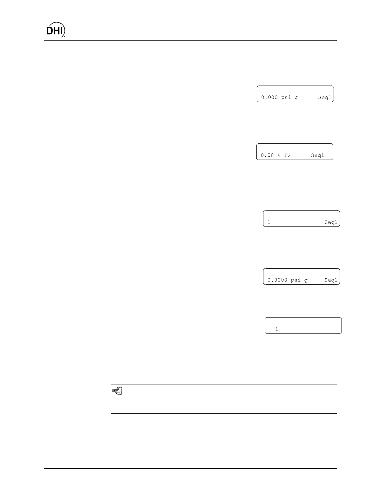
RPM3/HPMS A30000/ A6000- AF Operation and Mai ntenance Man ual
Select the desired pressure unit of measure for the Sequence. The unit of
measure selection screen is the current [UNIT] selection screen (see
Section 3.2.3) . Select the desir ed pr es s ur e measurement unit f or the Sequence.
The display is:
DUT full scale?
Enter the full s cale press ure of t he DUT t o be calibrat ed with t his File Sequenc e.
The value entered will be used along wit h the DUT toleranc e to det ermine RPM 3
function settings when the Sequence is run ( s ee S ec tion 3.2.11, PRINCIPLE).
The display is:
DUT tolerance?
Enter the tolerance (measurement uncertainty, pr ecision or accur acy as desired)
in % of full scale press ure of the DUT to be calibrated using t his F ile Sequence.
The value entered will be used along with the DUT full scale t o determine RPM 3
function settings when the Sequence is run ( s ee S ec tion 3.2.11, PRINCIPLE).
The display is:
Number of targets?
Enter the total number of pressure points or target pressures to be included in
the S equence. The maximum number of points is 21. If data is to be t aken at
“zero” pressure, include the “zero” points in the point count.
The display is:
Pressure target N:
Enter the numer ical value of the target pressure point <N>. Repeat until all of
the points in the Sequenc e hav e been defined.
After entering the last target pressure, the
Save as FileSeq #:
display is:
Enter the identifying number under which this Sequence definition file should
be saved. A confir mation is required to over wr ite and existing sequence.
Press [ESCAPE] to abandon the File Sequence f ile edits.
To create a Sequence File similar to a n exis ting Sequence F ile, w ithout reentering
all the Sequence information, edit an existing Sequence File and at the end o f
the editing process, s a ve it und er a d ifferent Sequence File number.
©2000 DH Instruments, Inc. Page 64
Page 75

RPM3/HPMS A30000/ A6000- AF Operation and Mai ntenance Man ual
3.4 [SPECIAL] MENU KEY
m
m PURPOSE
mm
Pressing [SPECIAL] accesses a menu of RPM3 functions and set tings that are less c ommonly
or NOT normally us ed in r egular oper ation. These include:
• <AutoZ> - Turn AutoZ O N/OFF, v iew and edit ZOFF S E T values (see Section 3.4.1).
• <SDS> - SDS is not used in RPM3 A30000/A6000- A F.
• <ATM> - View the current reading of the on-board baromet er ( s ee S ec tion 3.4.3).
• <Remote> - Set up RPM3 RS-232 (COM) and IEEE-488 (GPIB) interfaces (see
Section 3.4.4) .
• <Reset> - Ac c ess and execute a number if r es et options (see Section 3.4.5).
• <Cal> - View and adjust RPM3 RPT and barometer calibration coefficients (see
Sections 5.3, 5.2.2).
• <Intern> - View and set screen saver, keypad sounds, time and ID features (see
Section 3.4.7) .
• <Level> - View and change User Level prot ec tion of RPM3 functions (see Section 3. 4.8).
• <Log> - View the RPM3 incident log and run time clock ( s ee S ec tion 3.4.9).
m
m OPERATION
mm
To access the SPECIAL menu, press [SPECIAL] f r om the main run screen.
This display is:
1AutoZ 2SDS 3ATM
7Intern 8Level 9Log
Some screens, such as the SPEC IAL menu go beyo nd the two lines provided by the display. This
is indicated by a flashing a rrow in the second line o f the display. Use the [←←←←] and [→→→→] keys to
move the cursor to access the lines that are NOT visible or directly enter the number of the
hidden menu choice if you know it.
Select <1AutoZ> to turn the AutoZ func tion ON/OFF and view /edit ZOFFSET ( s ee
Section 3.4.1) .
↓
<2SDS> is not activ e as RP M3-30000/A6000 does not include the SDS function.
Select <3Atm> to view the current r eading of the on-board baromet er (see Section 3.4.3).
Select <4Remote> to set and adjust RPM3 remot e c om m unic ation interfaces ( s ee S ec tion
3.4.4).
Page 65 ©2000 DH Instruments, Inc.
Page 76

RPM3/HPMS A30000/ A6000- AF Operation and Mai ntenance Man ual
Select <5Reset> to use r es et functions (s ee S ec tion 3.4.5).
Select <6Cal> to view/edit RPT and barometer c alibr ations (see Section 3.4.6).
Select <7Intern> to change user operating preferences (see Sec tion 3.4.7).
Select <8Level> to change the securit y lev el ( s ee S ec tion 3.4.8).
Select <9Log> to view the incident log and run time clock (see Sect ion 3.4.9).
3.4.1 AutoZ
m
m PURPOSE
mm
To manage the AutoZ function for the active RPT and range including turning AutoZ
ON/OFF, viewing and editing Aut oZ values.
To run AutoZ (rezero the RPT range), use the [AutoZ] direct function key (see
Section 3.2 .10).
m
m PRINCIPLE
mm
How Auto Z Works
The main component of the change over time of the RPM3 RPT s is z ero drift or off set,
independent of span. Rezeroing RPM3 RPTs relative to a stable reference between
recalibrations allows lower measurement uncertainty specificat ions to be maintained wit h
a longer interval between full recalibrations. The RPM3 autozero function (AutoZ)
provides full on-board support for the rezeroing process to simplify its application by
the user.
The autozeroing func tion uses four parameters:
1) ZSTD: T he value of the aut ozero refer ence pressure as indicated by the r eference
autozero device.
For absolute RPTs in absolute measurement mode: The autozero pressure is
always atmospheric pressure and the ZSTD value can be supplied either:
• By manual entry.
• From a DHI RPM c onnec ted to the RPM3 CO M 2 por t.
• from the Lo RPT (A6000) for the Hi RP T (A30000).
For gauge RPTs or absolute RPTs in gauge measurement mode: The autozero
pressure is always zero (atmospher ic pressure) which is available by definition any time
the RPT is vent ed to atmosphere.
©2000 DH Instruments, Inc. Page 66
Page 77

RPM3/HPMS A30000/ A6000- AF Operation and Mai ntenance Man ual
2) ZCURERR: The difference between ZSTD and t he RPT indication at the autozero
pressure at some time after the RPT has been calibrated (ZCURERR = RPT
reading w/out ZO FFSET- ZSTD).
3) ZNATERR: The difference between Z STD and the RPT indic ation at the autozer o
pressure ju st aft er the RP T h as been cali brated (Z NATE RR = RP T reading w/ out
ZOFFSET - ZSTD). This value, when measured just after RPT calibration, is
referred to as the natural error at the autozero pressure. Because NO RPT is
perfectly linear and Z ST D is NOT perf ectly accurat e, the disagr eement bet ween the
RPT reading and ZSTD at the autozero pressure is unlikely t o ever be zero (exc ept
for gauge RPTs f or whic h the zero point is forced at calibration).
4) ZOFFSET: ZCURERR corrected for ZNATERR, represents the drift of the RPT
relative to the reference (ZOFFSET = ZCURERR - ZNATERR). The active RPT
reading, adjusted by ZOFFSET, is the autozeroed RPT reading (e.g., the RPT
reading corrected for zero drift since it was calibrated). F or an absolute RPT us ed
in gauge mode, ZOFFS ET also includes the value of at mospheric pressure that is
being subtracted t o arrive at gauge pressure.
The AutoZ function manages the determination, storage and application of ZNATERR
and ZOFFS ET individually for each RPM3 range and measur ement mode. ZNATERR
error is determined at the time of calibration (see Section 5.3.1.2). ZCURRERR and
ZOFFSET between calibrations are determined by running AutoZ using the [AutoZ]
direct funct ion k ey (see Section 3.2. 10) .
AutoZ On/Off
The AutoZ function can be turned ON and OFF. When AutoZ is ON, ZOFFSET is
always applied to the press ure meas ured by RPM 3 and new values of ZO FF SET c an be
determined by running AutoZ using the [AutoZ] key. When AutoZ is OFF, ZOFFSE T
is NOT applied (except for an absolut e RPT in gauge mode for which ZO FFSET is the
current value of atmospheric pressure which is always subtracted to achieve gauge
pressure) and Aut oZ cannot be run (s ee Sect ion 3.4. 1.1). In gauge m ode, t urning Aut oZ
OFF turns OFF the dynamic compensation for changes in atmospheric pressure (see
immediately below).
Gauge Mode with an Absolute RPT, Dynamic Compensation for
Atmospheri c P ressure
RPM3 supports gauge pr essure measurem ents with an absolut e RPT by subt racting t he
value of atmosphere (tare) from the RPT’s absolute measurement to arrive at a
gauge value. The appropriate tare value changes with the natural evolution of
atmospheric pres s ur e at a given location. For this reason, the v alue of the tare should be
redetermined by running AutoZ (see Section 3.2.10) when the RPT is vented to
atmospheric pressure. However, if atmos pheric pressure changes signif icantly between
running AutoZ, these changes in atmospher ic pressure are NOT eliminat ed by retaring.
To compensate for changes in atmospheric pressure between autozeroing (taring)
opportunities, dynamic atmospheric pressure compensation is used.
Page 67 ©2000 DH Instruments, Inc.
Page 78

RPM3/HPMS A30000/ A6000- AF Operation and Mai ntenance Man ual
RPM3’s on-board barometer measures atmospheric pressure independently from
the RPT. Between opportunities to update t he tare value by autoz eroing, the differ ence
between the on-board barometer reading at the t ime of the last t are and the current onboard barometer reading is used to compensate the tare value. This difference,
designated ATMO FFSET, is subtracted f rom the tare value. This dynamic atm ospheric
compensation technique r elies only on the resolution and s hort term stability of the onboard barometer, NOT its absolute accuracy or long term stability.
Dynamic compensation for atmospheric pressure, allows gauge measurements with an
absolute RPT with an additional uncertainty due to possible changes in atmospheric
pressure of only ± 0.00035 psi (2.5 Pa) without requiring an accurate
barometric reference.
Recommendations for the Use of the AutoZ Function
The AutoZ function provides a powerful and easy to use tool for improving the
measurement uncertainty specifications of an RPM3 and reducing the RPM3
recalibration interval by compensating for zero drift between full recalibrations. The
following simple recommendations will help assure that you use this feature to best
advantage.
• Always leave AutoZ ON when oper ating in t he gauge measurem ent mode. T he only
possible exception is in t he c as e of a malfunction of the on-board barometer.
• Be sure the RPM3 RPT is t ruly vent ed to at mospher e and allow at least t wo minutes
for full system stabilization before running AutoZ in or gauge mode.
• Always leave AutoZ ON when operating in the absolute measurement mode if
ZNATERR was set properly at calibration and the AutoZ routine using a valid
atmospheric reference has been run regularly.
• Execute the run AutoZ routine in absolute mode only when a reference whose
measurement uncertainty is known to be significantly lower than that of the RPM3
RPT is available. Keep range ratios in mind when comparing
measurement uncertainty. A ± 0.05 % FS barometer has roughly 37 times lower
measurement uncertainty than a ± 0.013 % FS 2 000 psi (1 MPa) RPT range
because the RPT/ baromet er range r atio is 10: 1. T herefor e, a
± 0.05 % barometer is
more than adequate to us e as an absolute mode AutoZ ref erence for any range of
RPM3 A30000/A6000-AF.
m
m OPERATION
mm
The AutoZ function and values are range AND mode (gauge or a bs o lute) sp ecific.
To access the RPM3 AutoZ function press
1off 2view H3
[SPECIAL] and select <1AutoZ>. The display is:
The menu applies to the c urrently active r ange and m eas urement mode.
Select <1off> (or <1on>) to change the AutoZ status for the active range and
measurement mode from ON to OFF or vice-ver s a (see Section 3.4. 1.1).
©2000 DH Instruments, Inc. Page 68
Page 79

RPM3/HPMS A30000/ A6000- AF Operation and Mai ntenance Man ual
Selecting <2view> allows the current value of ZOFFSET for the active range and
measurement mode to be viewed.
Selecting <3edit> allows the current value of ZOFFSET for the active range and
measurement mode to be edited.
3.4.1.1 AUTOZ ON/OFF
To turn AutoZ ON/OFF for the current range and measurement mode, press
[SPECIAL] and select <1AutoZ>.
If AutoZ is OFF f or the c urrent range and meas urement mode, <1on> is display ed in
the menu accessed by pr essing [SPECIAL] and s electing <1AutoZ>. Select <1on>
to turn AutoZ ON and return t o the main run screen.
If AutoZ is ON for the current range and measurement mode, <1off> is displayed in
the menu accessed by pr essing [SPECIAL] and s electing <1AutoZ>. Select <1off>
to turn AutoZ OFF and return to the main run s c r een.
AutoZ ON is indicated by a <z> displaying in the main run screen, top line, third
character from the right. When AutoZ is O F F , the cha racter is blank.
In absolute m ode, when AutoZ is OFF , the [AutoZ] key is disab led and ZOFF SET is
NOT applied .
In gauge mode, when AutoZ is OFF, the [AutoZ] key is disabled and “dynamic
compensatio n for atmospheric pressure” is OF F. ZOFFSET is still a pplied to tare
out atmospheric pressure.
3.4.1.2 VIEW AUTOZ
To view the curr ent ZOFFSET f or the active range and measurement mode press
[SPECIAL] and select <1AutoZ>, <2view>. The display is:
1
ZOFFSET absolute H3
3
ZOFFSET should be zero in absolute mode when the RPM3 is new or has just been
calibrated. ZOFFSET should be roughly equal to atmospheric pressure in gauge
mode.
2
1. Current measurement m ode.
Active range.
2.
Display field of current value of ZOFFSET.
3.
The value of ZOFFSET is alw ays displayed and entered in Pascal (Pa) regardless of
the current RPM3 measurement unit as RPM3’s internal operations are in Pa.
Page 69 ©2000 DH Instruments, Inc.
Page 80

RPM3/HPMS A30000/ A6000- AF Operation and Mai ntenance Man ual
3.4.1.3 EDIT AutoZ
The edit AutoZ function should be used with caution as entering inapprop riate values and
turning ON AutoZ may result in incorrect autozeroing and out of tolerance
measurements. In norma l operatio n, the value of ZOFF SET should be changed using the
run AutoZ function (see Sec tio n 3.2.10).
To edit ZOF FSET for the act ive range and measurement mode press [SPECIAL] and
select <1AutoZ>, <3edit>. The dis play is :
1
ZOFFSET absolute H3
3
The value of ZOFFSE T is always displayed and entered in Pascal (Pa) rega rdless of the
current RPM3 measurement unit. In gauge mod e, the value of ZOFFSE T is ap prox imately
atmospheric pressure.
3.4.2 SDS
m
m PURPOSE
mm
SDS is not used in RPM3 A30000/A6000-AF.
3.4.3 ATM
m
m PURPOSE
mm
To view the value of atmospheric pressur e as m easured by the on-board barometer.
2
1. Current measurement m ode.
Active range.
2.
Edit field for value of ZOFFSET.
3.
m
m PRINCIPLE
mm
RPM3 has an independent on-board bar ometer connect ed to t he ATM port on t he RPM3
rear panel. The atmospher ic pressure measurement s made by the on-board bar ometer
are only used for dynam ic compensation of atmospheric pres sure in gauge mode (see
Section 3.4.1) .
See Sections 1.2.2.2 and 5.2.2.
The on-board barometer is used only for measuring changes in atmospheric pressure
over short periods of time in gauge measurement mode. RPM3 measurement
uncertainty doe s not dep end on the abso lute meas urement unc ertainty o f the on-bo ard
barometer, only o n its resolutio n and s hort term rep eata bility (see Sectio n 3.4 .1, Ga uge
Mode with an Absolute RPT, Dynamic Compensation for Atmospheric Pressure).
©2000 DH Instruments, Inc. Page 70
Page 81

RPM3/HPMS A30000/ A6000- AF Operation and Mai ntenance Man ual
m
m OPERATION
mm
To view the current reading of the on-board barometer press [SPECIAL] and select
<4Internal>, <7Atm>. The display is in the current press ure units and curr ent res olution
setting of t he ac tive RPM3 range.
3.4.4 REMOTE
m
m PURPOSE
mm
To configure the RPM3 COM1, COM2 and IEEE-488 (GPIB) communication ports.
To test CO M 1 and COM2 communications .
m
m PRINCIPLE
mm
The RPM3 has two RS-232 communications ports refer red to as COM1 and COM 2 and
a single IEEE-488 (GPIB) port. CO M1 or the IEEE-488 port is f or communicating with a
host computer (see Chapter 4), and COM2 is reserved for communicating with an
external device (e.g., a multimeter, RPM, etc.). These ports can be set up from the
RPM3 front panel.
A self- test is supplied f or RS- 232 communic ations. T he self- test allows verif ication t hat
the RPM3 RS-232 ports (COM1 and COM2) are operating properly and that a valid
interface cable is being used. The test has two steps. In the first, COM1 sends a
message to COM2 and in t he second COM 2 sends a message t o COM1. I n each step,
RPM3 checks the message received at the receiving CO M port. If the receiving COM
port times out or receives an incorrec t message, that step of the t es t fails.
m
m OPERATION
mm
To access the port configurations press [SPECIAL] and select <4Remote>.
Select <1COM1>, <2COM2>, or <3IEEE-488> to view and edit that port’s settings.
Press [SPECIAL] and select <4Remote>, <4RS232test to ac c es s the RS-232 self tes t.
1) COM 1 and 2COM2
The COMx ports can be set for the specific settings required by the user.
These settings ar e baud, parity, lengt h and s top bit. The available opt ions are:
Baud: 300, 600, 1 200, 2 400, 4 800, 9 600, 19 200
Parity: NONE, ODD or EVEN
Length: 7 or 8
Stop Bit: 1 or 2
The default is 2 400, E , 7,1 for COM 1 and COM2.
The RPM3 appends a carriage return and a line feed to all messages that are s ent
out of the COM1 port to t he host . I t looks for a c arriage ret urn t o ter minate inc oming
messages and ignores line feeds . T he user M UST wait for a reply t o each mess age
sent to the RPM 3 before sending another mess age to it.
Page 71 ©2000 DH Instruments, Inc.
Page 82

RPM3/HPMS A30000/ A6000- AF Operation and Mai ntenance Man ual
2) IEEE-488
The IEEE-488 port address can be specified f r om 1 to 31.
The RPM3 sends a line feed and asserts the EOI line at the end of all
transmitted messages. It looks for a line feed and/or assertion of the EOI line to
terminate incom ing m es s ages .
3) RS-232 S elf-Test
The RS-232 Self Test is provided to check the RPM3 CO M ports and the interf ace
cable independently of an ext ernal device or computer. If you are having difficulty
communicating with RPM3 by RS-232 from a computer, the RS-232 self test can
help establish that t he RPM3 CO M1 port you are t rying t o com municat e with and the
interface cable you are using are good.
To run a self test of the RS-232 ports (COM1 and COM2) press [SPECIAL] and
select <4Remote>, <4RS232test>.
The display prompts you to connect COM1 to COM2 using the appropriate cable
(see Section 4.2.1).
Once the connect ion has been made, press [ENTER] to run the self test. The test is
first executed in the COM1
direction. If the COM1
proceeds to COM2
briefly followed by t he c onc lusion, <RPM3 RS232 test has PASSED> . If a test fails,
execution is suspended unt il [ENTER] is pressed.
The RPM3 RS-232 test can fail for three reasons: 1) The RS-232 cab le being used is
incorrect (see Section 4.2. 1 for inform a tio n o n the correct cab le); 2 ) COM1 a nd COM2
do NOT have the same serial communications settings and therefore cannot
communica te together (see Section 3.4. 4 to set the COM ports); 3) COM 1 or CO M2
is defective. The reason for failed communications is almost always a cable or
RS-232 interface settings problem. Be sure that these are correct before
concluding that a CO M port is defective.
3.4.5 RESET
m
m PURPOSE
mm
To reset various RPM3 settings to default or fac tory values.
RPM3 stores its user definable settings in non-v olatile memory. T he reset menu allows
the user to select ively or com pletely reset these sett ings to fac tory defaults. T his clear s
out any settings that the user has set up, and should be used only t o restore the RP M3
to a known state. RPM3 will go through its reboot routine after any type of reset is
selected.
→COM2 direction and then in the COM2→COM1
→COM2 test passes, <PASSED> dis plays brief ly and t he test
→COM1. If COM2→COM1 passes <PASSED> is displayed
©2000 DH Instruments, Inc. Page 72
Page 83

RPM3/HPMS A30000/ A6000- AF Operation and Mai ntenance Man ual
m
m OPERATION
mm
To access the reset choices, select <5Reset> under
the [SPECIAL] menu. T he display is:
3.4.5.1 RESET - SETS
m
m PURPOSE
mm
Clears all of the norm al us er s ettings for pres s ur e m eas ur em ents. This includes :
• Head settings set to disabled with <cm> as the height unit and <N2> as the
medium (see Sect ions 3.2.8 and 3.3.1).
• Sets the upper limits (UL) to fac tory defaults ( s ee S ec tion 3.2.5).
• Set the stability limits to ± 0. 005 % FS (see Section 3.3.4).
• Sets the auto zero ATMSTART measurement to 101.325 kPaa (see
Section 3.4.1) .
• Enables the auto read rate feature (see S ec tion 3.2.3).
• Sets the resolution to factor y defaults (see Sect ion 3.2.6).
• Sets the pressure units to <psi> (see Section 3.3.3).
1sets 2units 3seq
• Sets the measurement mode to <absolute> for ranges on absolute RPTs
and <gauge> for ranges on gauge RPTs ( s ee S ec tion 3.2.4).
• Enables auto zero for all ranges and measurement modes (see
Section 3.2.10) .
• Sets the range t o <H3> (see Section 3.2.2).
• Sets the beeper on valid k ey entry to <mid> (see Sect ion 3.4.7.2).
• Sets the Scr een s av er period to 10 minutes (see Section 3.4.7.1).
• Clears the previous leak check results (s ee S ec tion 3.3.5).
Page 73 ©2000 DH Instruments, Inc.
Page 84

RPM3/HPMS A30000/ A6000- AF Operation and Mai ntenance Man ual
3.4.5.2 Reset - units
m
m PURPOSE
mm
Resets unit and mode settings to defaults:
• Sets the six pressure unit selectable from [UNIT] to defaults (see
Section 3.2.3) .
• Sets the ref erence temperature for inches of water to 4 °C.
• Sets the user unit coefficient to 1.00/Pa (see S ec tion 3.3.2).
• Sets the act iv e pr essure unit to psi f or all r anges (see Section 3.2. 3) .
• Sets the act iv e measurement mode to default (see Sect ion 3.2.4).
3.4.5.3 Reset - seq
m
m PURPOSE
mm
Resets all Sequence relat ed v alues (see Section 3.2. 11) :
• Clears all File Sequence files ( s ee S ec tion 3.3.6.2).
• Resets the Quic k S equenc e s ettings (see Section 3.2.11.1) t o default values.
• Clears all Sequence data files (see Section 3.3. 6.2).
3.4.5.4 Reset - cal
m
m PURPOSE
mm
Use caution with this res et a s critica l ca lib ration data m a y b e d eleted .
This clears the user calibrations information, which affects the calibration of
the unit:
• Clears the user defined RP T calibrat ion coefficient s. PA/ PM to 0 (zer o) and
1 (see Section 5.3. 1.1).
• Clears the user defined barometer calibration. S ets P A/P M to 0 (z ero) and 1
(see Section 5.2.2).
• Clears the ZNAT E RR and ZOFFSE T values to 0 (zero) (see Section 3. 2.10).
©2000 DH Instruments, Inc. Page 74
Page 85

RPM3/HPMS A30000/ A6000- AF Operation and Mai ntenance Man ual
3.4.5.5 Reset - all
m
m PURPOSE
mm
To return RPM3 to the as delivered original f ac tory condition.
• Performs the functions of the Sets, Units, Seq, Cal resets (see Section
3.4.5).
• Resets the user s ec ur ity level to low (see Sec tion 3.4.8).
• Resets communicat ions port settings: COM1 and COM2 set to 2400,E,7,1
using <CR> and <LF> as the terminating characters. The IEEE-488
interface address is set to <10> (see Section 3. 4.4).
3.4.6 CAL
To calibrate the RP M3 Hi and Lo RPT s and adjust the on- board baromet er. T hese f unctions
are considered part of RPM3 maintenance and are therefore covered in the maintenance
section of this m anual (see Sections 5.3 and 5.2.2).
3.4.7 INTERN
m
m PURPOSE
mm
To access a menu of RP M3 internal operating pref erences and functions.
• Select <ScrSvr> - View and change the screen saver f unc tion (see Section 3. 4.7.1).
• Select <sounds> - View and change valid entry keypad sound settings (see
Section 3.4.7.2).
• Select <time> - View and edit the internal time and date settings (see
Section 3.4.7.3).
• Select <ID> - View the RPM3 serial number, view and edit the ID number (see
Section 3.4.7.4).
m
m OPERATION
mm
To access the Intern menu press [SPECIAL], and
select <7Intern>. The display is:
Select <1ScrSvr> to access the screen saver activation time menu ( s ee S ec tion 3.4.7.1).
Select <2sound> to access the keypad sounds choic es (see Section 3.4.7.2).
1ScrSav 2sound 3time
Select <3time> to access the tim e and date view/edit (see S ec tion 3.4.7.3).
Select <4ID> to access the S/N view and t he ID view/edit (see S ec tion 3.4.7.4).
Page 75 ©2000 DH Instruments, Inc.
Page 86

3.4.7.1 ScrSav
m
m PURPOSE
mm
To adjust the RPM 3 s c reen saver function.
m
m PRINCIPLE
mm
RPM3 has a screen saver function whic h causes t he display to dim aft er a front
panel key is NOT pressed f or a certain amount of time. This f unction is fact ory
set to activ ate after 10 minut es of inactivity but can be adjusted by the user .
m
m OPERATION
mm
To access the screen saver function press [SPECIAL] and select
<7Intern>, <1ScrSav>. Edit the tim e in minutes, after which screen s aver will
turn ON.
Setting screen saver time to zero eliminates the screen saver function so that
the display remains permanently at full brightness. The display may also be
completed sup p r ess ed us ing the s o ft [ON /OF F ] ke y (s ee Sectio n 3 . 1.4).
RPM3/HPMS A30000/ A6000- AF Operation and Mai ntenance Man ual
3.4.7.2 Sound
m
m PURPOSE
mm
To adjust or suppress the RPM3 keypad valid k ey pr es s s ounds .
m
m PRINCIPLE
mm
RPM3 provides audible feedback by a brief beep when a valid key press
is executed. T he frequency of this beep m ay be s elec ted from three choices or it
may be completely suppressed. Invalid key presses are indicated by a
descending two tone blurp which cannot be s uppr es sed (see Section 3.1.3).
m
m OPERATION
mm
To access the k eypad sound adjustment f unction press [SPECIAL] and select
<7Intern>, <2sound>.
Select between <2lo>, <3mid> or <4hi> to adjust the valid key press
tone frequency.
Select <1none> to suppress the valid key press s ound.
The sound function only affects the va lid key press tone.
©2000 DH Instruments, Inc. Page 76
Page 87

RPM3/HPMS A30000/ A6000- AF Operation and Mai ntenance Man ual
3.4.7.3 Time
m
m PURPOSE
mm
To view and edit the RPM 3 internal time and date settings.
m
m OPERATION
mm
To access the time function press
[SPECIAL] and select <7Intern>, <3time>.
The display is:
Select <1time> to edit the time. Edit hours, then minutes, then am/pm by
pressing [ENTER] at each ent ry. Seconds go to z er o when m inutes are entered.
Select <2date> to edit the date. The date must be specified in
YYYYMMDD format.
3.4.7.4 ID
m
m PURPOSE
mm
To view the RPM3 serial number (SN) and to view or edit the ID number.
m
m PRINCIPLE
mm
RPM3 has a factor y programmed serial number that is included on the product
label on the bottom of the case and can be viewed in the I D m enu.
Edit: 1time 2date
The RPM3 d ate and time a re set to United States M ountain Stand ard Time in
the final test and inspection pr ocess at the fa ctory. If desired, used the date
function to set your local time and date.
RPM3 also allows the user to store a unique alpha numeric ID number.
This feature is frequently used to assign an or ganizational contr ol ID such as an
asset number, t ool number , st andard number , et c. T he ID funct ion allows t he ID
number to be viewed and edited.
m
m OPERATION
mm
To access the I D func tion pr ess [SPECIAL] and selec t <7Intern>, <4Keypad>.
Select <1view> to view the current ID and serial number (SN).
Select <2edit> to edit the ID.
Page 77 ©2000 DH Instruments, Inc.
Page 88

RPM3/HPMS A30000/ A6000- AF Operation and Mai ntenance Man ual
The ID has twelve c haract ers. When t he edit sc reen is enter ed, the cur sor is on
the first c haracter. Numerical values can be ent ered directly from the keypad.
In addition, the [
available alpha numeric characters. Holding the key slews through the
characters. Character order going up ([
case letters, upper case let ters, num bers. Press [ENTER] t o select a character
and move to the next c haracter.
When a character is s elec ted the cursor moves to the next charac ter. T o leave a
blank character, [ENTER] with t he field f or that charac ter blank . Use this f or the
trailing characters if the ID being ent er ed is les s than 12 characters.
After the las t of the t welve charact ers has been enter ed, the < Save ID?> option
is offered. Select <1no> t o return t o the ID edit screen. Selec t <2yes> to save
the edited ID.
The ID can also be set remotely from a computer which is quite a bit more
convenient than writing it from the keyboard (see Section 4.4 .2 .8 ). ID ca nnot b e
cleared or reset by user commands.
←←←←] and [→→→→] keys can be used to toggle through a list of
→→→→]) is: blank space, symbols, lower
3.4.8 LEVEL
m
m PURPOSE
mm
To set user protection levels to restrict access to certain functions and to edit the
password required for c hanging us er lev els .
m
m PRINCIPLE
mm
RPM3’s front panel user interface provides the means to access all RPM3 user defined
data, settings and functions including calibration data. Inadvertent, uninformed or
unauthorized altering or deleting of data, sett ings and functions could require extens ive
reconfiguration by the user and might cause invalid readings or damage t o the system.
For these reasons , depending upon the applicat ion in which RPM3 is being used, it m ay
be desirable to restrict access to certain functions for certain users. The user level
function provides a m eans of rest rict ing access to cer tain f unctions . F our diff erent lev els
of security are available.
Access to changing s ec ur ity levels can be left open, or be protected by a pas s wor d.
Security Levels
The security lev els ar e s tructured to s uppor t typical operating envir onm ents as follows:
None This level is intended for use only by the system manager and/or
calibration facility. It allows access and editing in all areas including critical
metrological inform ation.
Low This level of security is designed to protect the specific metrological
information and system diagnostic and maintenance f unctions of the system.
It is intended for an advanced operator performing many different tasks.
©2000 DH Instruments, Inc. Page 78
Page 89

RPM3/HPMS A30000/ A6000- AF Operation and Mai ntenance Man ual
Medium This level of security is des igned to protect specific metr ological infor mation in
the system and to assure that the RPM3 is operated using consistent
operational parameter s .
High This level of security is designed to protect all operating parameters. It is
intended to minimize operator choices, for example to perform repeated
identical tests under c ons is tent conditions.
RPM3 is delivered with the security level set at low to avoid inadvertent altering of
critical internal settings but w ith access to changing security levels unrestricted. It is
recommended tha t the low security level b e maintained a t all times. If there is a risk of
unauthorized changing of the security level, changing authority should be password
protected (see Section 3.4. 8 ).
The high security level disables remote com municatio ns and returns a n error mes sage to
all remote commands. All other security levels have NO effect on
remote communications.
The security levels are structured to support typical levels of operation and to prevent
execution of the X ’d f unc tions as shown in Table 6.
Table 6. Functions - Security Levels
FUNCTION LOW MEDIUM HIGH
[RANGE]
[UNIT]
[MODE]
[UPPER LIMIT] ( c hange set t ing)
[RES]
[RES] (change sett ing)
[DISPLAY]
[HEAD]
[SDS]
[AutoZ] (in absolute mode)
[ENTER], <1QukSeq> or <2Fi l eSeq> )
[ENTER], <1QukSeq> or <2Fi l eSeq> ( m ake changes)
[SETUP], <1Head>
[SETUP], <2PresU>
[SETUP], <3ReadRt> (change stat us)
[SETUP], <4Stab> (change set ting)
[SETUP], <6Seq>
[SPECIAL], <1AutoZ>
[SPECIAL], <1AutoZ>, <1on/OFF>
[SPECIAL], <1AutoZ>, <3edit>
[SPECIAL], <2SDS>
[SPECIAL], <3Atm>
[SPECIAL], <4Remote> ( access)
[SPECIAL], <4Remote> ( m ake changes)
[SPECIAL], <5Reset>
XX
XX
XX
XX
XX
XX
XX
XX
XX
XX
XX
XX
XX
X
X
X
X
X
X
X
X
X
X
X
X
Page 79 ©2000 DH Instruments, Inc.
Page 90

RPM3/HPMS A30000/ A6000- AF Operation and Mai ntenance Man ual
Table 6. Functions - Security Levels (Continued)
FUNCTION LOW MEDIUM HIGH
[SPECIAL], <5Reset>, <3com>
[SPECIAL], <5Reset>, <4cal>
[SPECIAL], <5Reset>, <5all>
[SPECIAL], <6Cal>
[SPECIAL], <6Cal>, <1RPT>, <2edit>
[SPECIAL], <6Cal>, <1RPT>, <3run ZNATERR>
[SPECIAL], <6Cal>, <2barometer>, <2edit>
[SPECIAL], <7Intern>
[SPECIAL], <7Intern>, <3Time> (make changes)
[SPECIAL], <7Intern>, <4ID>, <2edit>
[SPECIAL], <9Log> (v ie w)
[SPECIAL], <9Log> (clear log)
[SPECIAL], <9Log> (clear r un t im e)
Remote communications disabled X
m
m OPERATION
mm
XXX
XXX
XXX
XX
XXX
XXX
XXX
X
XXX
XXX
X
XXX
XXX
RPM3 is delivered with NO active password so access to t he User Level menu is open.
The user level is set to <1Low>. User levels can be changed freely unt il a password has
been created.
To access the User Level function, press [SPECIAL] and select <8Level>. If NO
password yet exists or if the cor r ec t password has been entered.
The display is:
Selecting <1change> user level brings up the
1change user level
Restriction: 1none
restriction m enu. The display is:
You can then select the current restriction level, or [ESCAPE] back to the main
run screen.
Selecting <2edit password> displays the user
password and allows it to be edited. Pass words c an
Password:
pppppp
be up to six numbers in lengt h and cannot st art with
a zero.
Once a password has been entered, the user level cannot be changed without reentering
the password.
If 0 (zero) is ent ered, then the password is made inac tive and a password will NOT be
required to access the user level menu. This is the factory def ault with a security level
of <2low>.
©2000 DH Instruments, Inc. Page 80
Page 91

RPM3/HPMS A30000/ A6000- AF Operation and Mai ntenance Man ual
If there is an active password, the RPM3
password entry screen appears. The user must
enter the user defined password or the factory
secondary passwor d to proceed any furt her :
The first field <nnnn> is the s erial number of t he RPM3, followed by a s econd field <xx>
that represents the number of times that a secondary password has been used.
This second field increments each time a secondary password is used. T he third field,
<pppppp>, is for nor m al pas s wor d entry.
The factory secondary password is available in case the user’s password has been
misplaced or forgotten. It can be obtained by contacting a DHI Authorized Service
Center. The factory secondary passwo rd is different for all RPM3’s and changes each
time it is used.
3.4.9 LOG
m
m PURPOSE
mm
To view and/or clear the RPM3 event log; to view the RPM3 run-time clock.
m
m PRINCIPLE
mm
RPM3 SN
nnnn-xx
pppppp
RPM3 records t o a log eac h time one of the following events occurs:
• Pmax! is exceeded (see Section 3.2. 5.1).
• A memory fault occurs.
The log may be viewed. The information can be useful in diagnosing an
overpressure event. RPM3 accumulat es power -on time.
RPM3 also maintains a run-time clock. The clock accumulates time that the RPM3 is
under line power. Soft OFF tim e c ounts as run time (s ee S ec tion 3.1.4).
m
m OPERATION
mm
To view the event log or run-time clock pres s [SPECIAL] and select <9Log>.
Select <1log> to view the event log.
The oldest logged event appears. P ressing [ENTER] steps thr ough the logged events
from the oldest to the most recent and ending with the option to clear the log.
Select <YES> or <NO>. If NO ev ents have been logged, <End of log> displays.
RPM3 suppo rts a d uplica te facto ry lo g that cannot b e viewed or cleared by the user.
Select <2runtime> to view the run-time clock.
The total accumulated run-time is displayed. The unit of measure is hours with
0.1 hour resolution.
Page 81 ©2000 DH Instruments, Inc.
Page 92

RPM3/HPMS A30000/ A6000- AF Operation and Mai ntenance Man ual
4. REMOTE OPE RATION
4.1 OVERVIEW
Most of the RP M3 front panel functions can also be executed by c om m ands from a remote computer .
The host computer can communicate to the RPM3 using the RPM3 COM1 RS-232 port or the
IEEE-488 port.
4.2 INTERFACING
Sending a message to the RP M3 places it in rem ote mode. T he remot e indicator t o the bott om right
of the display lights when the RPM3 is in remote mode. It will also flicker when a message is
received. The menus usually accessed from the front panel are locked out while in remote.
[ESCAPE] returns the RPM3 to local operation unless the SYST EM:KLO CL O N command was us ed
to lock out keypad oper ation.
4.2.1 RS-232 INTERFACE
4.2.1.1 COM1
The RPM3 COM1 RS- 232 interf ace is loc ated on t he r ear panel. It is a 9- pin f emale
DB-9F connector configured as a DCE device. Data is transmitted out of RPM3
using pin 2 and is received on pin 3. This allows a norm al pin-to-pin DB-9M to DB-
9F RS-232 cable to be used to connect to a DTE host. Handshaking is NOT
required or supported.
Table 7. RPM3 COM1 DB-9F Pin Designations
PIN # FUNCTION DESCRIPTION
2 TxD This pin transmits serial data from t he RPM3 t o t he host.
3 RxD This pin accepts serial data from the host computer.
5 Grn This pin is the common return for the TxD and RxD signals.
Table 8. IBM PC/XT DB-9F, DB-9M Connections
IBM PC/XT DB-9F CONNECTIONS
DB-25M DB-9F DB-9M DB-9F
2333
3222
7555
IBM PC/XT DB-9M TO RPM 3 DB9F
CONNECTION
Page 82 ©2000 DH Instruments, Inc.
Page 93

RPM3/HPMS A30000/ A6000- AF Operation and Mai ntenance Man ual
4.2.1.2 COM2
The RPM3 COM2 RS-232 interface is located on the rear panel. It is a 9-pin male
DB-9M connector configured as a DTE devic e. Data is t ransmitt ed out of the RP M3
using pin 3 and is received on pin 2. This allows a normal pin-to-pin DB-9F to
DB-9M RS-232 cable to be used to connect to a DCE slave. Handshaking is NOT
required or supported. COM2 can be used to allow c ommunication to other RPM3s
by connecting the Host port to the first RPM3’s COM1 port, and then connecting
COM1 of the sec ond RP M 3 to the COM2 port of the first RP M 3. This method can be
used to chain multiple RPM3s together using t he SYS:COMM:THRU command.
Table 9. RPM3 COM2 DB-9M Pin Designations
PIN # FUNCTION DESCRIPTION
2 RxD This pin accepts ser ial data f r om anot her RPM3 or anot her device.
3 TxD This pin transmits serial data from the RPM3 to another RPM3 or
another device.
5 Grn This pin is the common return for t he TxD and RxD signals.
4.2.2 IEEE-488 (GPIB)
The RPM3 IEEE-488 interface is located on the rear panel. The physical and electrical
interface conforms to IEEE Std 488.1-1987 Subset E2 and IEEE Std. 488.2-1992. You
should NOT attempt to communicate with the IEEE-488 interface while using the COM1
interface. The IEEE-488 receive buffer is 250 bytes deep. The RPM3 will hold off release of
the NRFD handshake line until it can service and empty the receive buffer. This keeps the
buffer from overflowing.
4.3 REMOTE COMMAND SYNTAX AND STYLE
4.3.1 LOCAL AND REMOTE SETTING
When in local mode, each of the three ranges of each of t he (up to) two RPTs has it s own
settings (unit , mode, resolution, stabilit y) (see Section 3.2.2) t hat are set range specifically
and remain with the range. When ranges are changed, the settings change to those that
were last set in t hat range. Sett ings c hange as r anges are changed. In r emote, each RPT is
treated as a channel and the settings are common to all t he ranges of one RPT. The only
range specific set tings are calibr ation and AutoZ settings. When you change ranges on one
RPT the sett ings rem ain the sam e. Changes m ade t o the set tings while in remot e mode will
remain when operation is swit c hed bac k to local mode.
Page 83 ©2000 DH Instruments, Inc.
Page 94

RPM3/HPMS A30000/ A6000- AF Operation and Mai ntenance Man ual
4.3.2 COMMAND SYNTAX
The remote command set for the RPM3 uses SCPI, 1992.0 (Standard Communications
Protocol for Instruments) syntax and f ormat. Commands are grouped into subsyst ems that
contain related keywords in a hierarchic al str uctur e in a comm and tree. These keywor ds are
strung together to c reate a c ommand. A colon (:) is a header separ ator that separates eac h
keyword as you move down eac h level or node of the command tree. The beginning of a
command message does NOT require a colon (:), but one is allowed.
Each keyword has a long form and a short form. The short form is always shown in
uppercase, while the remaining lower case letter s indicat e the long f orm. Either long or shor t
form use is allowed and the RP M 3 is c as e ins ens itive to these com m ands . Brackets ([ ]) ar e
used to identify optional keywords that ar e the default keyword for a particular node.
4.3.3 QUERIES AND REPLIES
Many commands require additional parameters, some r equire NO additional param eters , and
many also have a query form. Some commands are only queries. A question mark (?)
immediately following a command spec ifies a query. Commands for t he COM1 port and the
IEEE-488 port use the same style and syntax, but differ slightly in their responses from
RPM3. When using the IEEE-488 port , only queries generate a reply from the RPM3. When
using the COM1 port, every command gener ates a reply, and the user mus t wait for the reply
before sending another com mand. For COM1 non-query c ommands, t he RPM3 replies with
an <OK> or <ERROR>. This maintains s y nc between the host and the RP M 3.
4.3.4 MULTIPLE COMMANDS
Multiple commands may be sent within a single message to the RPM3 if desired.
These commands m us t be separated by a semicolon (;) and t he tot al mess age length cannot
exceed 80 characters. E ach command mus t be preceded by a colon (:) ( unless you wish to
reference the previous command node (discussed later)). Query replies to such messages
are returned in a single reply message with eac h reply separated by a semic olon (;). If you
send multiple commands in a single message to the COM1 port, each query generates a
reply and each non-query command generates an <OK> response, with a semicolon (;)
separating each reply within the reply message.
Example:
PC
RPM3
PC → RPM3 (COM1): “SYST:VER?;:DISP:BLAN 10;:ABOR”
RPM3
→ RPM3 (GPIB): “SYST:VER?;:DISP:BLAN 10;:ABOR”
→ PC (GPIB): “1992.2”
→ PC (COM1): “1992.2;OK;OK”
©2000 DH Instruments, Inc. Page 84
Page 95

RPM3/HPMS A30000/ A6000- AF Operation and Mai ntenance Man ual
When using multiple commands, you may reference the previous command level by NOT
preceding the command with a colon (:). RPM3 interprets the command starting at the
command level defined by the preceding command in the message. This level must be
established by the f ir s t command of a mess age.
Example:
To set the RPM 3 COM1 port to 2 400 baud, even parity, 7 bit word length and one
stop bit, you c ould s end:
“COMM:SERIAL:TRAN:BAUD 2400;PAR EVEN;BITS 7;STOP 1”
Because this mess age actually cont ains four com mands, the r eply from t he RPM3 if
using the RPM3 COM1 por t would be:
“OK;OK;OK;OK”
4.3.5 COMMAND PARAMETERS
Command parameters can be required or optional. There must be at least one space
preceding the first parameter. Additional parameters are preceded by a comma (,).
Parameters which depend on a unit of measure (e.g., pressure or head height) are
interpreted in the c urrent def ault unit unless a unit suf fix f ollows t he paramet er separ ated by
at least a space. Wher e indicat ed, spec ific k eywords c an be used in place of paramet ers f or
MIN, MAX and DEFAULT paramet er v alues that are det er m ined by the RPM3. B r ac k ets ([ ])
are used to identify optional parameters. In some cases, quer ies m ay allow par am eters.
4.3.6 SUFFIXES
In some cases, a numeric suffix can follow a keyword t o differentiate between the Hi RPT
and the Lo RPT. 1 accesses the Hi RPT , and is the ass umed RPT if a suff ix is NOT given.
2 accesses t he Lo RP T (if present) . The comm and descriptions indicate an optional suffix by
the use of [n] where n can be 1 or 2.
4.3.7 PROGRAMMING TIPS
4.3.7.1 SCPI AND IEEE-488.2
The RPM3 uses a rem ote command syntax and format based on the S CP I (Standard
Commands for Programmable Ins truments) language (see Section 4. 3). SCPI has
been adopted because it provides the benefits of a standardiz ed logical st r uc ture and
common command syntax for users of programm able test instruments . Those that
have developed programs for other SCPI c ompliant instruments will find t he RPM3
command set familiar and eas y to understand. Firs t time SCPI users need to take
some time to becom e familiar with the hierar chical SCPI commands . At f irst, these
will seem complex, espec ially when compared with the simple linear command set
used with older DHI products. In fact, they offer gr eater versatilit y and commonality
with other program m able test instrum ents.
Page 85 ©2000 DH Instruments, Inc.
Page 96

RPM3/HPMS A30000/ A6000- AF Operation and Mai ntenance Man ual
RPM3 also supports IEEE-488.2 common and stat us commands.
LabVIEW® drivers are available for the RPM3. These drivers allow users of the
®
National Instruments’ LabVIEW
more RPM3s using LabVIEW
commands directly. The RPM3 LabVIE W
environment to create systems that include one or
®
virtual instruments instead of using the remote
®
drivers are an abstraction of the remote
commands into a consistent set of common and specific instrument functions.
The drivers can be obtained at NO charge from the DHI web site
www.dhinstruments.com.
4.3.7.2 PROGRAMMING TECHNIQUE
The following six step procedure can be used to create a program which acquires
pressure data over the RPM3’s remote interface.
Establish communications with the RPM3 via RS-232 or IEEE488:
RS-232 (COM1): To establish serial communicat ions, the PC and RPM3 must
be configured to have mat ching baud rates , parity, data bits, and st op bits. The
PC’s COM port must be connected to the RPM3’s CO M1 port using a straightthrough DB9M-to- DB9F cable (see Section 4.2.1). The RPM3 COM1 port can
be configured locally from the f ront panel by pressing [SPECIAL] and select ing
<4Remote> (see Section 3.4.4).
RPM3 supports an independent RS-232 self test to verify that the RPM3
RS-232 p orts a re op erating correctly a nd the interface cab le being used is va lid.
Use this self test to trouble sheet if you are having difficulty establishing
communications over RP M 3 C OM1 (see Section 3.4.4 ).
IEEE-488: To establish IEEE-488 communications, the PC must have an
IEEE-488 card and the RPM3 must be correctly addressed (see Section 4.2.2).
The RPM3’s IEEE-488 address can be set locally from the front panel by
pressing [SPECIAL] and selecting <4Remote> (see Section 3.4.4). An IEEE-
488 interface cable must be used.
Send the command “*IDN?” and read the response (see Section 4.4.2.1).
Scan the response for the string “RPM3”. This verifies that communications
have been successfully established and t hat t he instr ument connect ed is act ually
an RPM3.
When in high security user level (see Section 3.4.8), remote commands are
locked out. This mode is set from the front panel. Any attempt to
communicate remotely when locked out by the user level results in an error. The
error query remote command (see Section 4.4.2.8) is the only remote command
that will function when remote co m m a nd s a re lo ck ed o ut b y the us er level.
©2000 DH Instruments, Inc. Page 86
Page 97

RPM3/HPMS A30000/ A6000- AF Operation and Mai ntenance Man ual
Set the pressure units for the desired RPT:
Send the command “UNIT[n] P
RESUNIT” (where n equals 1 to select the Hi RPT
and 2 to select t he Lo RPT). F or example, to set t he measurement unit s on the
lo RPT to psi, send the command “UNIT:PRESsure2 PSI”. Note that the
keyword “PRESsure” is optional for this command, so the command “UNIT2
PSI” would have the same effect (see Section 4.4.2.9).
Set the pressure measurem ent mode for the desir ed RP T:
Send the command “UNIT[n]:P
RPT and 2 to select t he Lo RPT . W here P
RESMODE” (where n equals 1 to select the Hi
RESMODE equals A to select absolute
and G to select gauge. For ex ample, to set the measur ement mode on the Lo
RPT to gauge, send the command “UNIT:PRESsure:MODE G” (see Section
4.4.2.9).
Star t and get a new pressure meas ur em ent:
Send the command “MEASure[n]? Lo|Mid|Hi” (where n equals 1 to select the
Hi RPT and 2 to select the Lo RPT). This com mand allows the RPT range and
resolution for a pressur e measurement to be def ined. For example, to read the
pressure using Range 2 (the Mid range) of the Lo RPT send the command
“MEASure2:PRESsure? MID”. Note that the resolution is an optional
parameter and was NO T sent in this example ( s ee S ec tion 4.4.2.2).
Obtain information related to the last measurement cycle:
Use the “FETCh[n]?” command. The “FETCh[n]?” command does NOT
initiate a new pressure reading cycle and therefore can be used to quickly obtain
previously initiated pr essur e readings. For ex ample, t o read the pr essure rat e of
change that was associated with the measurement cycle of Step
above, send
the command “FETCh2:Rate?” (see Section 4.4.2.).
Read the pres s ur e Ready status associated with the last measurement cycle:
Use the “CALCulate:STABility[n]:LIMIT:FAIL?”. This command allows the
Ready/Not Ready status of the previous pressure measurement to be
determined (see Section 3.1.2). For example, send the command
“CALCulate:STABility2:LIMIT:FAIL?” to read the stability dependent r
Ready/Not Ready value associated with the reading made in Step
above
(<0> if Ready, <1> if Not Ready) ( s ee S ec tion 4.4.2.3).
The preceding procedure utilizing the “MEASure” command is recommended for
single pressure readings. This command is simple to use since it allows the
selection of RPT, range and resolution, initiates a pressure measurement cycle and
reads the result all in a single command. The drawback of combining all these
functions in a single command is that it takes several seconds to execute and
includes functions that are NOT necessary when repeating measurements. The
preferred method when taking repeated readings from a specif ic RPT and range is t o
first use the “CONFigure” command to set the range and resolution and then to
repeatedly use the “READ” command to start and get the pressure measur ements
on the current range. The following comm ands could be used t o perform the sam e
test as described above instead of using the measure command: “CONFigure2
Mid” followed by “READ2?” ( s ee S ec tion 4.4.2.2).
Page 87 ©2000 DH Instruments, Inc.
Page 98

RPM3/HPMS A30000/ A6000- AF Operation and Mai ntenance Man ual
In fact, if RPM3 is already set up as needed for the measurements t o be made, the
only command that is needed to collect data is the READ[n]? command. For the
test above, the command to send to read pressure from the current range is
“READ2?”.
Table 10. Quick Programming Tips
IN ORDER TO: USE COMMAND NOTES
Set the pressure units. UNIT[n] PRESUNIT Use UNIT:MODE to set gauge or
absolute measurement mode.
Read the pressure using the
current range of the specified
READ[n]?] Remember to turn SDS OFF, if
present, prior to t aking a reading.
RPT, in current measurement
units and resolution.
Turn SDS OFF or ON for the
specified RPT.
Set the RPT and range and
read the pressure.
SDS[n] OFF|ON SDS is not present on RPM3
A30000/A6000-AF.
CONF[n] L o | Mid|Hi followe d
by READ1[n]?
As an alternate, Meas[n]?
Lo|Mid|Hi also works but contains
redundant functions when used
repeatedly on the same range.
Determine the pressure
stability rate dependent
Ready/Not Ready condition
CALC:STAB[n]:LIMIT:FAIL?
Returns <0> when previous
reading was Ready (within
stability criterion).
for a pressure reading.
Read the pressure rate of
change associated with a prior
FETC[n]:RATE? Fetch can also be used to reread
the last pressure.
pressure reading.
Set the head height. CALC:HEAD:HEIGht HEIGHT Send UNIT:HEIGht IN|CM pr ior to
setting the head height.
Turn ON AutoZ for the
specified RPT.
CAL[n]:ZERO:STATe ON This enables AutoZ on t he current
range. The setting applies to
other ranges on the same RPT
when the range is changed.
Run AutoZ on a specified RPT
and range to specify the value
CAL[n]:ZERO:AUTO
NCE,ZSTD]
[O
of ZSTD and determine a new
ZOFFSET for a given range
and measurement mode.
Check if the upper limit was
SENS[n]:PROT:TRIP? SENS[n]:PROT:CLE is used to
exceeded.
See if any errors have
SYST:ERR?
occurred.
Have the RPM3 screen
CONF[n]:R
correspond to a specific RPT
and range.
©2000 DH Instruments, Inc. Page 88
Prior to executing this command
the range must be selected using
the CONF command and the
measurement mode must be
selected using the UNIT:MODE
command.
clear this flag.
ANGE This command affects the
display. READ and MEAS
commands do NOT.
Page 99

RPM3/HPMS A30000/ A6000- AF Operation and Mai ntenance Man ual
4.4 COMMANDS
Table 11. Com mand Summary
Items inside brackets [ ] are optional. A ‘|’ character signifies a logical ‘or’.
[n] specifies the RPT channel (‘1’ Hi, ‘2’ Lo. Default is ‘1’).
[nn] specifies the optional RPT range from 1 to 3 (default is ‘1’).
COMMAND PARAMETERS NOTES
*CLS
*ESE
*ESR?
*IDN?
*OPC
*OPT?
*RSE
*RSR?
*RST
*SRE
*STB?
*TST?
Command only
0..255
Query only
Query only
None
Query only
0..255
Query only
Command only
0..255
0..255
Query only
Clears the queues and status registers
Event status enable register
Event status register
Identify software ver sion and hardwar e
Operation complete
Operation identification
RPT ready status enable register
RPT ready status event register
Reset to default settings
Service request register
Status byte
System self test results
:ABORt
:CALCulat e
:HEAD
:HEIGht
:MEDium
:DENSity
:STABility[ n]
:LIMIT
:FAIL?
:CALibra tion[n]
:AMBient
[:PRESsure]
:DATE
:RPT[nn]
:DATE
:ZERO
:STATe
:AUTO
:OFFSet[nn]
:ABSolute
:GAUGe
:NATerr[nn]
:CONFigure[n]
[:PRESsure]
Halt current measurement cycle
HeadHeight
N2|He|Air|Oil|H20|User
Density
Stability
Query only
Adder, Multiplier
YYYY,MM,DD
Adder, Multiplier
YYYY,MM,DD
0 |1 |OFF|ON
ONCE
Absolute ZOFFSET
Gauge ZOFFSET
ZNATERR
range, resolution Configure RPT for range and resolution.
Height difference of RPM3 and DUT
The pressure medium
The user defined pressure medium density
Stability limit
Stability limit Ready status
Baromet er PA/PM
Barometer calibration date
RPT range PA/PM
RPT range calibration date
AutoZ on/OFF
Run AutoZ
ZOFFSET for absolute mode
ZOFFSET for gauge mode
ZNATERR (absolute mode only)
:DISPlay
BLANking
PAGE
RPT?
:FETCh[n]
:[PRESsure]?
:RATE?
…...
0..99 min
1..7
Query only
……
Query only
Query only
…...
Screen saver period
Changes the DISPLAY function
Gets all 3 of the RPT range values
…...
Press result from a previous measur em ent
Rate result from a previous measur em ent
Page 89 ©2000 DH Instruments, Inc.
Page 100

COMMAND PARAMETERS NOTES
:INITiate[ n]
[:IMMediat e]
:CONTinuous
RPM3/HPMS A30000/ A6000- AF Operation and Mai ntenance Man ual
Table 11. Com mand Summary (Cont inued)
Items inside brackets [ ] are optional. A ‘|’ character signifies a logical ‘or’.
[n] specifies the RPT channel (‘1’ Hi, ‘2’ Lo. Default is ‘1’).
[nn] specifies the optional RPT range from 1 to 3 (default is ‘1’).
…...
Command only
0|1|OFF|ON
…...
Starts a new single measurement cycle
Disable/Enable continuous measurement
:MEASure[ n]
[:PRESsure]?
:RATE?
SENSe[n]
[:PRESsure]
:PROTection
:LEVel
:TRIPped?
:CLEar
:AVERage
:COUNt
:AUTO
:READ[n]
[:PRESsure]?
:RATE?
:STATus
:OPERatio n
:CONDition?
:NTRAnsition
:PTRAnsition
[:EVENt]
:ENABle
:INSTrument
:CONDition?
:NTRAnsition
:PTRAnsition
[:EVENt]
:ENABle
:ISUMmary[n]
:ABSolute
:GAUGe
:CONDition?
:NTRAnsition
:PTRAnsition
[:EVENt]
:ENABle
…...
range, resolution
range, resolution
…...
Upper Limit
Upper Limit
Query only
Command only
0..10
0 |1|OFF|ON
…...
Query only
Query only
Query Only
0..32767
0..32767
0..32767
0..32767
Query Only
0..32767
0..32767
0..32767
0..32767
Query Only
0..32767
0..32767
0..32767
0..32767
…...
Start and get new pressure m easur em ent
Start and get new rate m easur em ent
......
The absolute mode upper limit (UL) alarm
The gauge mode limit (UL) alarm
Check if UL has been exceeded
Clears the “TRIPped” flag
The # of measurements t o aver age
Disable/enable the auto read rate
…...
Start and get new pressure m easur em ent
Start and get new rate m easur em ent
Read the condition register
Reads or sets the negative transition f ilter
Reads or sets the positive transition filter
Reads or sets the event register
Reads or sets the event enable
Read the condition register
Reads or sets the negative transition f ilter
Reads or sets the positive transition filter
Reads or sets the event register
Reads or sets the event enable
Read the condition register
Reads or sets the negative transition f ilter
Reads or sets the positive transition filter
Reads or sets the event register
Reads or sets the event enable
©2000 DH Instruments, Inc. Page 90
 Loading...