

Page 1

Hand Held Controller
PN 2671068
July 2006
© 2006 Fluke Corporation. All rights reserved. Printed in USA
All product names are trademarks of their respective companies.
HHC3
Users Manual
Page 2

Warranty and Product Support
Fluke Biomedical warrants this instrument against defects in materials and
workmanship for one full year from the date of original purchase. During the
warranty period, we will repair or, at our option, replace at no charge a product
that proves to be defective, provided you return the product, shipping prepaid,
to Fluke Biomedical. This warranty does not apply if the product has been
damaged by accident or misuse or as the result of service or modification by
other than Fluke Biomedical. IN NO EVENT SHALL FLUKE BIOMEDICAL
BE LIABLE FOR CONSEQUENTIAL DAMAGES.
Only serialized products and their accessory items (those products and items
bearing a distinct serial number tag) are covered under this one–year warranty.
PHYSICAL DAMAGE CAUSED BY MISUSE OR PHYSICAL ABUSE IS
NOT COVERED UNDER THE WARRANTY. Items such as cables and nonserialized modules are not covered under this warranty.
Recalibration of instruments is not covered under the warranty.
This warranty gives you specific legal rights, and you may also have other
rights, which vary from state to state, province to province, or country to country. This warranty is limited to repairing the instrument to Fluke Biomedical’s
specifications.
Warranty Disclaimer
Should you elect to have your instrument serviced and/or calibrated by someone other than Fluke Biomedical, please be advised that the original warranty
covering your product becomes void when the tamper-resistant Quality Seal is
removed or broken without proper factory authorization. We strongly recommend, therefore, that you send your instrument to Fluke Biomedical for factory
service and calibration, especially during the original warranty period.
Page 3

Notices
All Rights Reserved
Copyright 2006, Fluke Biomedical. No part of this publication may be reproduced, transmitted, transcribed, stored in a retrieval system, or translated into any language without the written
permission of Fluke Biomedical.
Copyright Release
Fluke Biomedical agrees to a limited copyright release that allows you to reproduce manuals and
other printed materials for use in service training programs and other technical publications. If
you would like other reproductions or distributions, submit a written request to Fluke Biomedical.
Unpacking and Inspection
Follow standard receiving practices upon receipt of the instrument. Check the shipping carton for
damage. If damage is found, stop unpacking the instrument. Notify the carrier and ask for an
agent to be present while the instrument is unpacked. There are no special unpacking instructions,
but be careful not to damage the instrument when unpacking it. Inspect the instrument for physical damage such as bent or broken parts, dents, or scratches.
Technical Support
For application support or answers to technical questions, either email
techservices@flukebiomedical.com
Claims
Our routine method of shipment is via common carrier, FOB origin. Upon delivery, if physical
damage is found, retain all packing materials in their original condition and contact the carrier
immediately to file a claim. If the instrument is delivered in good physical condition but does not
operate within specifications, or if there are any other problems not caused by shipping damage,
please contact Fluke Biomedical or your local sales representative.
or call 1-800- 648-7942 or 1-425-446-6945.
Page 4

Standard Terms and Conditions
Refunds and Credits
Please note that only serialized products and their accessory items (i.e., products and
items bearing a distinct serial number tag) are eligible for partial refund and/or credit.
Nonserialized parts and accessory items (e.g., cables, carrying cases, auxiliary modules,
etc.) are not eligible for return or refund. Only products returned within 90 days from the date
of original purchase are eligible for refund/credit. In order to receive a partial refund/credit of a
product purchase price on a serialized product, the product must not have been damaged by the
customer or by the carrier chosen by the customer to return the goods, and the product must be
returned complete (meaning with all manuals, cables, accessories, etc.) and in “as new” and resalable condition. Products not returned within 90 days of purchase, or products which are not in
“as new” and resalable condition, are not eligible for credit return and will be returned to the customer. The Return Procedure (see below) must be followed to assure prompt refund/credit.
Restocking Charges
Products returned within 30 days of original purchase are subject to a minimum restocking fee of 15 %. Products returned in excess of 30 days after purchase, but prior to 90
days, are subject to a minimum restocking fee of 20 %. Additional charges for damage
and/or missing parts and accessories will be applied to all returns.
Return Procedure
All items being returned (including all warranty-claim shipments) must be sent freight-prepaid to
our factory location. When you return an instrument to Fluke Biomedical, we recommend using
United Parcel Service, Federal Express, or Air Parcel Post. We also recommend that you insure
your shipment for its actual replacement cost. Fluke Biomedical will not be responsible for lost
shipments or instruments that are received in damaged condition due to improper packaging or
handling.
Use the original carton and packaging material for shipment. If they are not available, we recommend the following guide for repackaging:
Use a double-walled carton of sufficient strength for the weight being shipped.
Use heavy paper or cardboard to protect all instrument surfaces. Use nonabrasive
material around all projecting parts.
Use at least four inches of tightly packed, industry-approved, shock-absorbent
material around the instrument.
Page 5

Returns for partial refund/credit:
Every product returned for refund/credit must be accompanied by a Return Material Authorization (RMA) number, obtained from our Order Entry Group at 1-800-648-7952 or 1-425-446-
6945.
Repair and calibration:
To find the nearest service center, go to www.flukebiomedical.com/service
In the U.S.A.:
Cleveland Calibration Lab
Tel: 1-800-850-4606
Email: globalcal@flukebiomedical.com
Everett Calibration Lab
Tel: 1-800-850-4606
Email: service.status@fluke.com
In Europe, Middle East, and Africa:
Eindhoven Calibration Lab
Tel: +31-402-675300
Email: ServiceDesk@fluke.com
In Asia:
Everett Calibration Lab
Tel: +425-446-6945
Email: service.international@fluke.com
Certification
This instrument was thoroughly tested and inspected. It was found to meet Fluke Biomedical’s
manufacturing specifications when it was shipped from the factory. Calibration measurements
are traceable to the National Institute of Standards and Technology (NIST). Devices for which
there are no NIST calibration standards are measured against in-house performance standards using accepted test procedures.
or
WARNING
Unauthorized user modifications or application beyond the published specifications may result in
electrical shock hazards or improper operation. Fluke Biomedical will not be responsible for any
injuries sustained due to unauthorized equipment modifications.
Restrictions and Liabilities
Information in this document is subject to change and does not represent a commitment
by Fluke Biomedical. Changes made to the information in this document will be incorporated in new editions of the publication. No responsibility is assumed by Fluke Biomedical for the use or reliability of software or equipment that is not supplied by Fluke Biomedical, or by its affiliated dealers.
Manufacturing Location
The HHC3 Hand Held Controller is manufactured in India for Fluke Biomedical, 6920 Seaway Blvd.,
Everett, WA, U.S.A.
Page 6

Page 7

Table of Contents
Chapter Title Page
1 Introduction and Specifications.............................................. 1-1
Introduction .......................................................................................... 1-1
Safety.................................................................................................... 1-1
Specifications........................................................................................ 1-3
2 Using the Controller................................................................. 2-1
Controls and Connectors....................................................................... 2-1
Connecting the Controller to a Simulator ............................................. 2-1
Connecting the Controller to a PC........................................................ 2-1
Powering the Controller........................................................................ 2-7
Adjusting the Beeper Level............................................................... 2-7
Adjusting the Viewing Angle ........................................................... 2-7
Command Types................................................................................... 2-8
Single-Key and Dual-Key Commands.............................................. 2-8
Immediate Commands ...................................................................... 2-10
Stepped Commands .......................................................................... 2-10
Factory Sequences ................................................................................ 2-11
User Sequences..................................................................................... 2-11
Replacing the Batteries ......................................................................... 2-12
3 Programming User Sequences ............................................... 3-1
Entering User Defined Mode................................................................ 3-1
Defining User Sequences...................................................................... 3-2
Specifying the Advance Technique .................................................. 3-5
Viewing and Editing User Sequences............................................... 3-7
Deleting Commands...................................................................... 3-9
Editing Commands........................................................................ 3-10
Skipping Command Editing.......................................................... 3-16
Adding Commands ....................................................................... 3-20
Deleting All User Sequences ............................................................ 3-23
Running a Factory or User Sequence.................................................... 3-24
4 Using the Application Software .............................................. 4-1
Introduction .......................................................................................... 4-1
Installing the HHC-Utility Software..................................................... 4-1
Connecting the Controller to a PC........................................................ 4-5
i
Page 8

HHC3
Users Manual
Testing the Connection......................................................................... 4-6
Downloading User Sequences.............................................................. 4-7
Uploading User Sequences................................................................... 4-8
Error Messages..................................................................................... 4-10
Appendices
A Dual-Key Commands ................................................................... A-1
B Factory Sequences........................................................................ B-1
ii
Page 9

List of Tables
Table Title Page
1-1. Symbols............................................................................ 1-2
2-1. Controls and Connectors .................................................. 2-3
2-2. Start Up Sequence ............................................................ 2-7
2-3. Single-Key Commands..................................................... 2-8
A-1. Dual-Key Commands ....................................................... A-1
B-1. Factory Sequences (medSim 300B) ................................. B-1
B-2. Factory Sequences (MPS450 and Marq III)..................... B-5
List of Figures
Figure Title Page
2-1. Controls and Connectors .................................................. 2-2
2-2. Back Panel........................................................................ 2-3
2-3. Connecting the Controller to a Simulator......................... 2-6
2-4. Replacing the Batteries..................................................... 2-12
4-1. Connecting the Controller to a PC.................................... 4-5
iii
Page 10

HHC3
Users Manual
iv
Page 11

Chapter 1
Introduction and Specifications
Introduction
The HHC3 Hand-Held Controller (hereafter called the “Controller”) facilitates
the direct selection of parameters for the Fluke Biomedical medSim 300B,
MPS450, and Marq III simulators. The Controller uses telephone receiver
cable for connection to a simulator. The Controller provides for single-key
commands, dual-key commands, factory-defined sequences, or easy
programming of user-defined sequences. It displays the current waveform
selection and the user prompt on the alphanumeric display.
Safety
WXWarning. Read before using the Controller.
To avoid personal injury, follow these guidelines:
• Do not use in any manner not specified in the Users
Manual. Otherwise, the protection provided by this product
may be impaired.
• Always press power off on the Controller and unplug the
Battery Eliminator before cleaning the outer surface.
• Inspect the product. If the Controller appears damaged or
appears to operate in a manner not specified in the
manual, DO NOT CONTINUE USE. Return for service.
• Avoid spilling liquids on the Controller; fluid seepage into
internal components creates corrosion and a potential
shock hazard. Do not operate the instrument if internal
components are exposed to fluid.
Do not open this product. There are no user replaceable
parts.
1-1
Page 12

HHC3
Users Manual
WCaution
Calibrate the Controller annually. Only qualified technical
personnel should perform troubleshooting and service
procedures on the Controller.
Do not expose the Controller to temperature extremes.
Ambient operating temperatures should remain between
15 and 35 °C. Temperature fluctuation above or below this
range may adverse affect the Controller.
Refer to Table 1-1 for descriptions of symbols found on the Controller.
Table 1-1. Symbols
Symbol Description
W See Users Manual.
X
P
"
~
Caution risk of electric shock
Manufacturer’s declaration of
product compliance with applicable
EU directives
Battery Eliminator Port
Do not mix with solid waste stream.
Dispose of using a qualified recycler
or hazardous material handler.
1-2
Page 13

Introduction and Specifications
Specifications
1
Specifications
Size......................................................................... Height: 16.00 cm (6.30 in); Width: 8.10
Weight (with batteries) ......................................... 0.36 kg (0.8 lbs)
Environmental....................................................... Indoor use
Temperature, Operating ....................................... 15 to 35
Temperature, Storage........................................... 0 to 50
Maximum Humidity, Operating ........................... 80 % relative humidity up to 31
Maximum Humidity, Storage .............................. 95 %
Altitude .................................................................. Up to 2000 m
Power
medSim 300B .....................................................RS232 cable supplied
MPS450, Marq III................................................ Four AA Alkaline batteries or battery
Battery Power Supply
Four alkaline AA cells, non-rechargeable
Voltage ............................................................... 1.5 x 4 VDC
Battery Life (continuous use) .............................. 60 hours
Battery Eliminator Supply
Output Voltage ................................................... 9 VDC
Output Current ................................................... 50 mA
Display ................................................................... 2 x 16 LCD, adjustable viewing angle
Controls ................................................................. 20 control keys and ON/OFF power
Interface ................................................................ RS232 bi-directional interface. Auto
cm (3.19 in); Depth: 3.58 cm (1.41 in)
°C (59 to 95 °F)
°C (32 to 122 °F)
°C
°F), decreasing linearly to 50 %
(88
relative humidity at 40
eliminator
switch. Embossed keys in 4x5 matrix
connect to Simulator parameters.
°C (104 °F).
1-3
Page 14

HHC3
Users Manual
Standard Accessories
Users Manual ..................................................... PN 2671068
CD (Users Manual, Application SW) .................. PN 2671031
Serial Interface Cable (medSim 300B) ............... PN 2712829
Serial Interface Cable (MPS450, Marq III).......... PN 2702279
Serial Adapter Cable .......................................... PN 2702287
AA Alkaline Batteries (4)..................................... Duracell MN1500 LR8 1.5 Volts (or
Instruction Cards
medSim 300B .................................................. PN 2671046
MPS450 and Marq III....................................... PN 2671022
Optional Accessories
Battery Eliminator ............................................... PN 2720054
Compatible Simulators
medSim 300B Base Model
medSim 300B w/CO Option
medSim 300B w/Option 1 Options
medSim 300B w/CO and Option 1 Options
MPS450 Base Model
MPS450 w/ CO Option
MPS450 w/ Fetal/Maternal ECG/IUP Option
MPS450 w/CO and Fetal/Maternal ECG/IUP Options
Marq III (GE Medical Systems OEM based upon the MPS450)
Modes of Operation
Single Key
Dual Key
Factory Sequence
User Sequence
equivalent)
1-4
Page 15

Chapter 2
Using the Controller
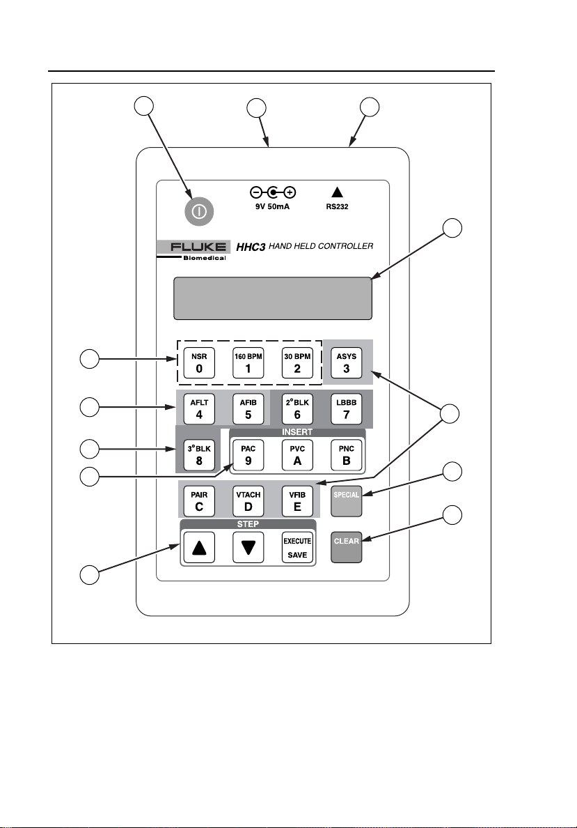
Controls and Connectors
Refer to Figures 2-1 and 2-2 and Table 2-1 for an introduction to the controls
and connectors.
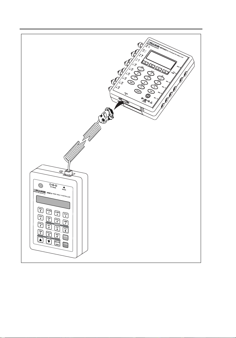
Connecting the Controller to a Simulator
Use the Serial Interface Cable (PN 2712829) for connecting to the medSim
300B simulator. Use the Serial Interface Cable (PN 2702279) for connecting to
the MPS450 or Marq III simulator. Refer to Figure 2-3 for a sample view of
the connection to the MPS450.
Connecting the Controller to a PC
Chapter 4 describes software installation and hardware connections for
uploading and downloading files.
2-1
Page 16
HHC3
Users Manual
12
11
10
1
9
2
3
4
5
6
2-2
7
8
ems001f.eps
Figure 2-1. Controls and Connectors
Page 17
Using the Controller
Connecting the Controller to a PC
13
14
Figure 2-2. Back Panel
2
ems034f.eps
Table 2-1. Controls and Connectors
Item Name Description
A A Power on/off key. Press on, press off.
B Battery eliminator connector. For use when connected to the
MPS450 or Marq III simulator.
C RS232 serial port connector. Telephone style connector to attach the
RS232 cable from the simulator.
D Display LCD, 2x16, adjustable viewing angle.
2-3
Page 18

HHC3
Users Manual
Table 2-1. Controls and Connectors (cont.)
Item Name Description
E Ventricular Arrhythmias E immediately commands asystole.
N immediately commands a pair of
PVCs.
O immediately commands
ventricular tachycardia.
P immediately commands
ventricular fibrillation.
F Q Initiates selection of dual-key
commands.
G U Stops execution of dual-key command
and returns to the previous menu
screen.
STEP keys S moves to the next selection.
R moves to the previous selection.
T sends the stepped command to
the simulator.
I INSERT keys K immediately commands a PAC.
L immediately commands a PVC.
M immediately commands a PNC.
J Conduction Arrhythmias H immediately commands a second
degree A-V block, type 1.
I immediately commands a left
bundle branch block.
J immediately commands a third
degree A-V block.
2-4
Page 19

Using the Controller
Connecting the Controller to a PC
Table 2-1. Controls and Connectors (cont.)
Item Name Description
2
K Supra Ventricular
Arrhythmias
G immediately commands coarse
atrial fibrillation.
F immediately commands atrial
flutter.
L NSR Rate B accesses series of NSR rates.
Press
R or S to navigate, T to
send command.
C immediately commands an NSR
rate of 160 BPM (Sinus Tachycardia)
D immediately commands an NSR
rate of 30 BPM (Sinus Bradycardia)
M Instruction Cards Lists of dual-key selections. One list
documents dual-key commands sent to
the medSim 300B. A second list
documents commands sent to the
MPS450 and Marq III.
N Battery Compartment Four AA alkaline batteries.
2-5
Page 20
HHC3
Users Manual
HHC3
MPS450
2-6
Figure 2-3. Connecting the Controller to a Simulator
ems032f.eps
Page 21
Using the Controller
Powering the Controller
2
Powering the Controller
With the medSim 300B, the Controller receives power via the RS232 cable.
With the MPS450 and Marq III, use four alkaline batteries or the Battery
Eliminator (PN 2720054).
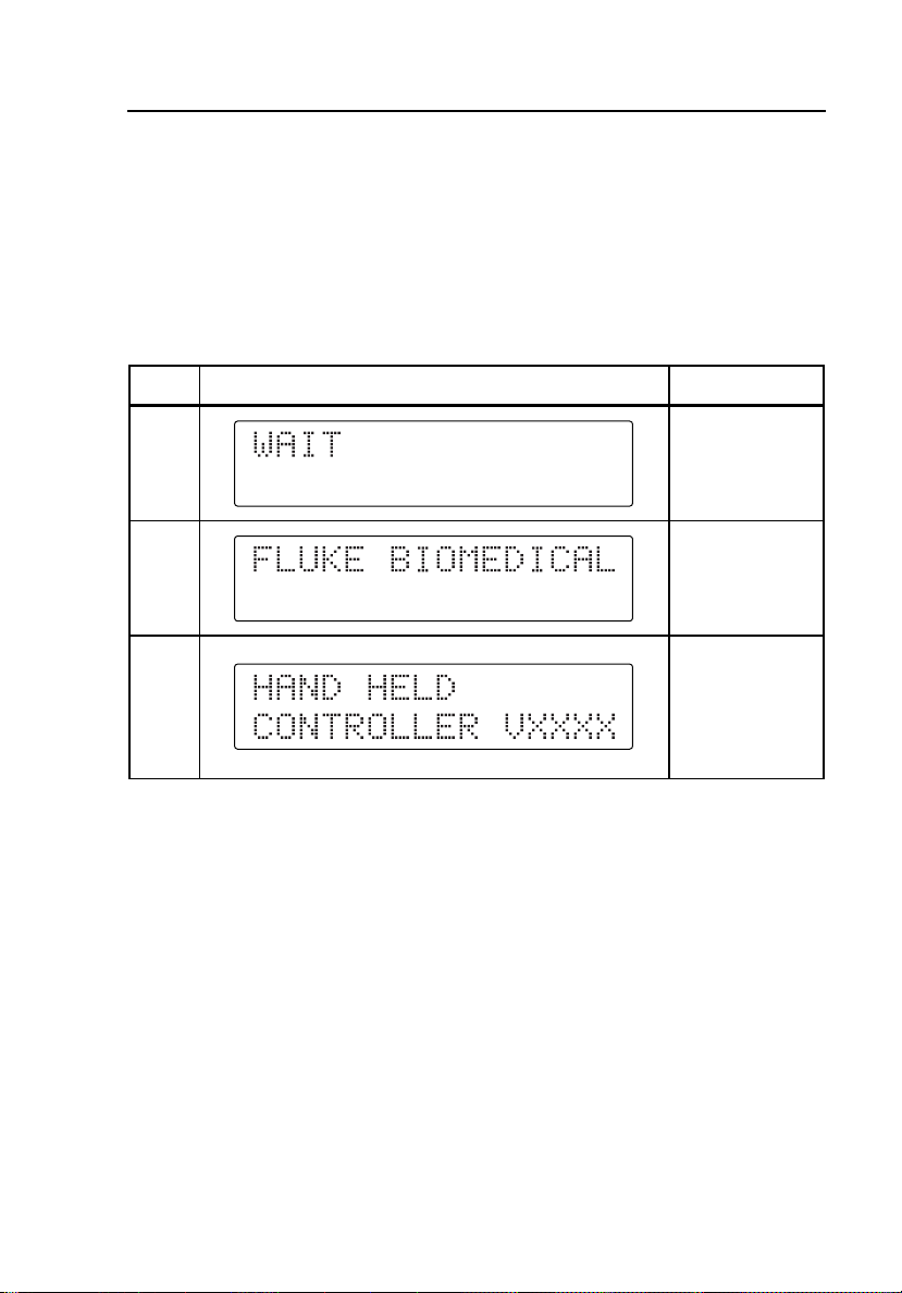
Press A to power on the Controller. Refer to Table 2-2 for the sequence of
keys and display screens you will encounter during the power-on process.
Table 2-2. Start Up Sequence
Press Display Notes
2 second delay
A
2 second delay
Firmware
number,
2 second delay
Adjusting the Beeper Level
The Controller emits a single beep at power on and after any valid key press.
An invalid key press yields a double beep. Begin adjusting the Controller
beeper level by pressing Q I N. Then press R or S to select a
new level.
Adjusting the Viewing Angle
Begin adjusting the Controller viewing angle by pressing Q I E.
Then press R or S to select a new angle.
2-7
Page 22

HHC3
Users Manual
Command Types
Single-Key and Dual-Key Commands
There are 15 single-digit keys (0-E) on the Controller. Each command appears
on its respective key. Most single-digit keys act immediately: the Controller
sends the command when you press the key. However, the B key requires
that you also take at least one more step with the Sor R key, and then
press T.
Key
B
S
R
T
C
D
Refer to Table 2-3 for descriptions of the single-key commands.
Table 2-3. Single-Key Commands
Description
NSR Rate (Stepped)
NSR Rate 30 BPM NSB30 NSR30 NSR30
NSR Rate 40 BPM NSR40 NSR40
NSR Rate 45 BPM NSR45 NSR45
NSR Rate 60 BPM NSB60 NSR60 NSR60
NSR Rate 80 BPM NSB80 NSR80 NSR80
NSR Rate 90 BPM NSR90 NSR90
NSR Rate 100 BPM NSR100 NSR100
NSR Rate 120 BPM NSB120 NSR120 NSR120
NSR Rate 140 BPM NSR140 NSR140
NSR Rate 160 BPM NSB160 NSR160 NSR160
NSR Rate 180 BPM NSR180 NSR180
NSR Rate 200 BPM NSB20 NSR200 NSR200
NSR Rate 220 BPM NSR220 NSR220
NSR Rate 240 BPM NSB240 NSR240 NSR240
NSR Rate 260 BPM NSR260 NSR260
NSR Rate 280 BPM NSR280 NSR280
NSR Rate 300 BPM NSB300 NSR300 NSR300
NSR Rate 160 BPM
Sinus Tachycardia
NSR Rate 30 BPM
Sinus Bradycardia
NSB160
NSB30
Command Sent on Serial Port to Simulator
medSim
300B
MPS450
NSR160
NSR30
Marq III
NSR160
NSR30
2-8
Page 23

Using the Controller
Command Types
Table 2-3. Single-Key Commands (cont.)
Key
G
F
O
P
E
N
H
I
J
K
L
M
Description
Supra Ventricular Arrhythmias
Atrial Fibrillation, coarse
Atrial Flutter
Ventricular Arrhythmias
Ventricular Tachycardia VTC
Ventricular Fibrillation VFB1
Asystole
Pair of PVCs
Conduction Arrhythmias
Second degree A-V
block, type1
Left Bundle Branch
Block
Third degree A-V block
Premature Beat
Insert PAC
Insert PVC
Insert PNC
Command Sent on Serial Port to Simulator
medSim
300B
AF1
AFL
ASYS
PAIR
2DB1
LBB
3DB
IPAC
IPVC
IPNC
MPS450
AF1
AFL
VTC
VFB1
ASY
PAIR
2DB1
LBB
3DB
PAC
PVC1S, PVC2S PVC1S, PVC2S
PNC
AF1
AFL
VTC
VFB1
ASY
PAIR
2DB1
LBB
3DB
PAC
PNC
2
Marq III
Start a dual-key command by pressing Q, followed by the two keys for the
command (for example, B and C.) If this dual-key command offers no
further selections, the Controller sends it to the simulator immediately. With
other dual-key commands, you will need to take at least one more step by
pressing S or R to make a selection from a list of commands. Send the
selected command by pressing T. Refer to Appendix A for descriptions of
dual-key commands.
2-9
Page 24
HHC3
Users Manual
Immediate Commands
The Controller will act upon single-key and dual-key commands either
immediately or after you complete at least one additional step.
The Controller sends many commands as soon as you press a single key or
complete a dual-key sequence. These are immediate commands: no other
selection is necessary. The Controller display identifies each immediate
command.
All single-digit commands except B are immediate. For a dual-key
immediate command example, press Q B K, which yields the
following display:
The Controller sends this command to the simulator without further action.
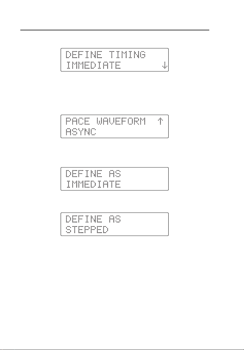
Stepped Commands
Pressing a single-key or selecting the second key in a dual-key sequence can
require a secondary selection. These are stepped commands: additional
selections may be required. The display identifies such a command with up and
down arrow symbols. You press R or S to make the stepped command
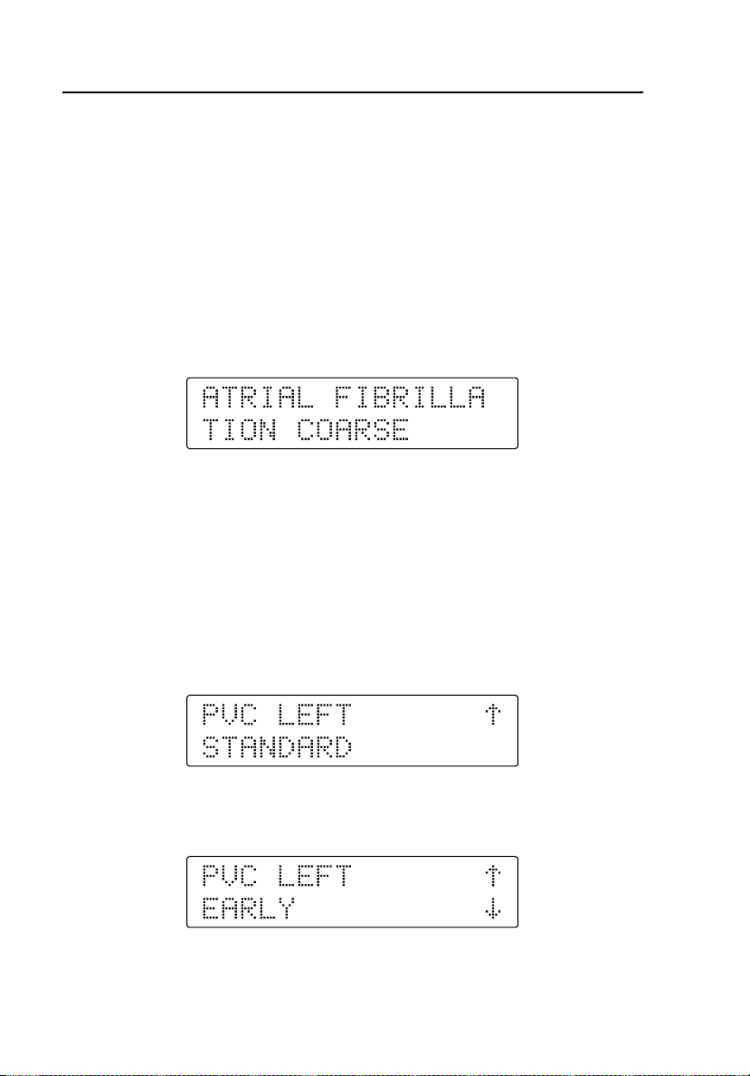
selection. For example, pressing Q C G yields the following display:
Pressing R at this point accesses the next selection for this stepped
command, as follows:
With the required selection displayed, press T to send the command to the
simulator.
2-10
Page 25

Using the Controller
Factory Sequences
2
Factory Sequences
The Controller features several pre-programmed common test sequences
referred to as factory sequences. Start a factory sequence by pressing Q,
followed by the two keys for the sequence. Access factory sequences for the
medSim 300B by using dual keys G J through H E. Access
factory sequences for the MPS450 or Marq III by using dual keys L G
through M D. Factory sequences are immediate commands. The display
changes to identify each part of the sequence.
Note
With the Controller connected to the medSim 300B, you can also
access four user-defined sequences programmed on that simulator.
Access these sequences with keys H F through H I.
Refer to Appendix B for descriptions of factory sequences for the medSim
300B and MPS450/Marq III simulators.
User Sequences
User sequences allow you to set up test programs using the Controller’s
keypad. You will be able to program the user-defined command by selecting
up to 100 steps involving existing single- or dual-key commands and userentered delay times and termination techniques. You can set up user sequences
for dual keys K B through L F. Refer to Chapter 3 for a detailed
discussion of these user sequences.
2-11
Page 26
HHC3
Users Manual
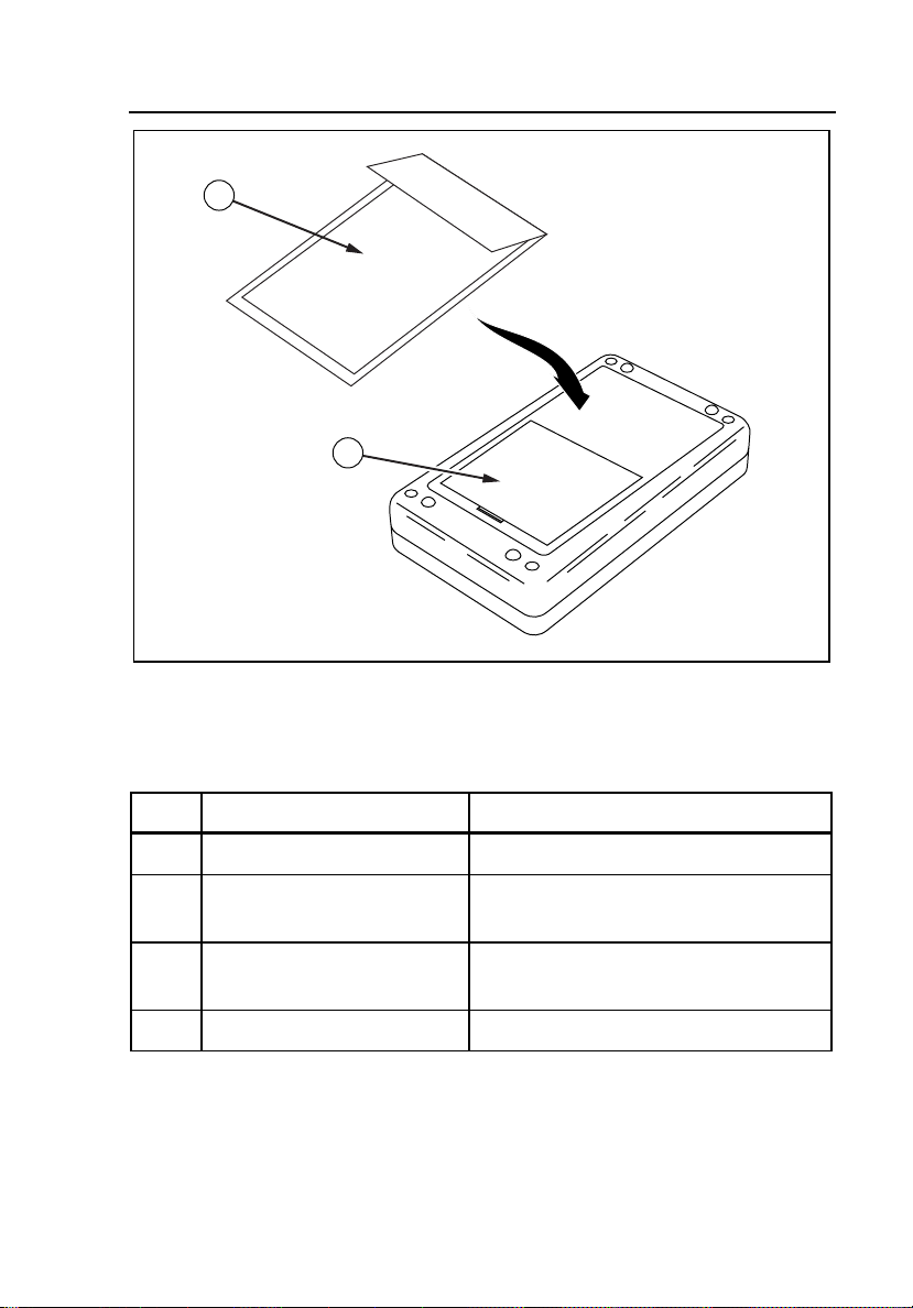
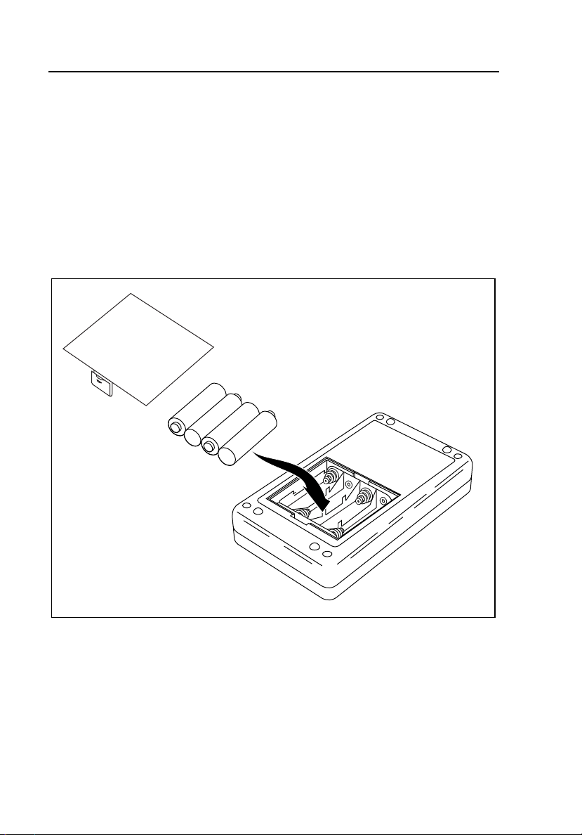
Replacing the Batteries
If you are using the Controller with the MPS450 or Marq III simulator, either a
battery or a battery eliminator will be required. Refer to Figure 2-4 when
removing and installing the batteries. The battery eliminator connects at the top
of the Controller.
Note
Use the battery eliminator whenever possible, especially when
running long-term test sequences.
2-12
Figure 2-4. Replacing the Batteries
ems002f.eps
Page 27

Chapter 3
Programming User Sequences
Entering User Defined Mode
You can define user sequences for the dual keys from 90 to A4. These user
sequences form a set of dual-key commands existing for each simulator. You
can define these sequences with different types of intermediate delays between
each command in the sequence.
Note
Press U to go to the previous menu.
Use these steps to define user sequences:
1. Turn off the Simulator and the Controller.
2. Connect the Controller and any one of the simulators (medSim 300B,
MPS450, Marq III) and then switch the Simulator on.
3. While holding down the T on the Controller, switch ON the Controller.
4. Continue to hold T until the display shows WAIT. After the Power up
display appears, the Controller displays the menu for the Start up mode:
5. You have three choices for defining user sequences at this point:
DEFINE
VIEW/EDIT (allows for Deleting, Editing, Skipping Editing, and Adding)
DELETE ALL
3-1
Page 28
HHC3
Users Manual
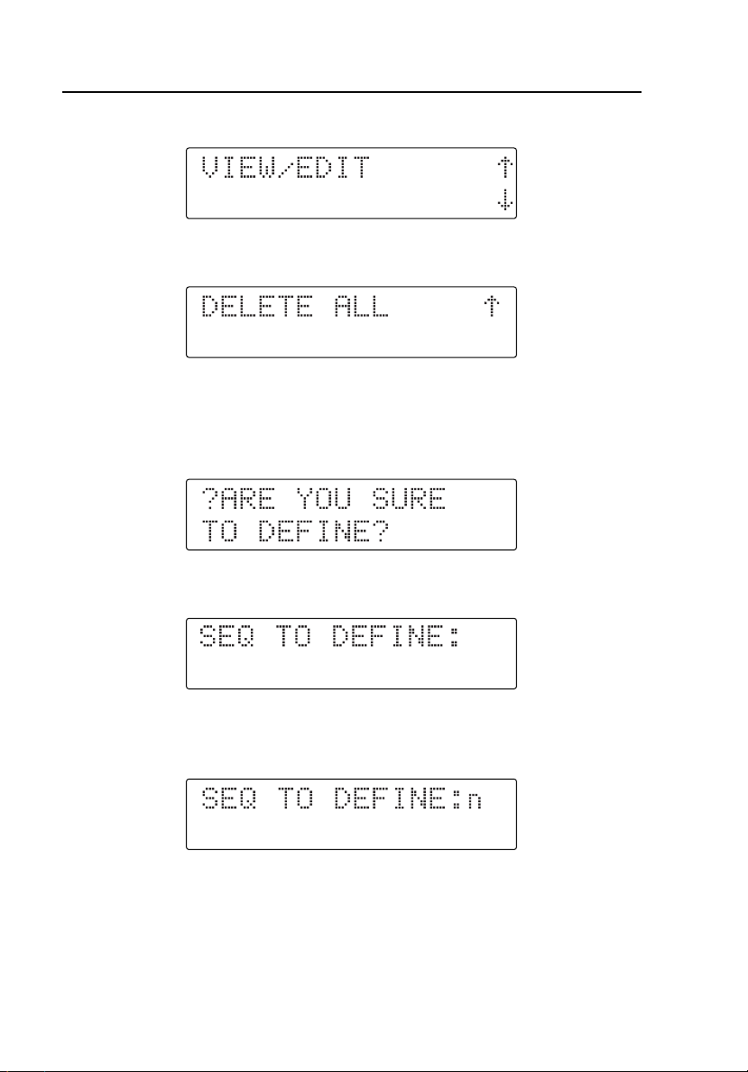
Press T to enter Define, or press S for View/Edit; the display shows:
Press R for Define or press S for Delete All; the display shows:
Defining User Sequences
1. Press T at the DEFINE menu. The display shows:
2. Press T to confirm. The display shows:
3. Press the first digit of the user-programmable dual keys (from K B
to L F). The display shows:
3-2
Page 29
Programming User Sequences
Defining User Sequences
3
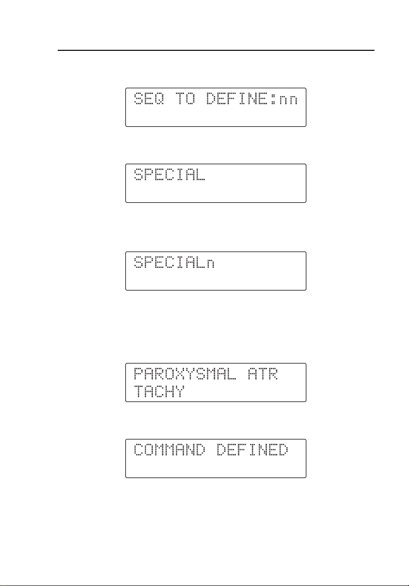
4. Press the second digit of the user-programmable dual keys. The display
shows:
5. Press Q to begin entering the dual key command. The display shows:
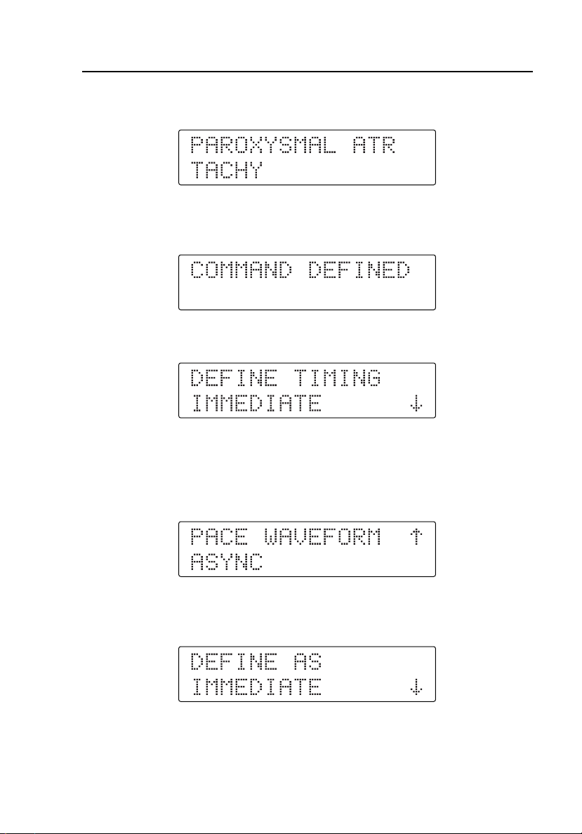
6. Press the first digit (from B to J) of the chosen two-digit waveform.
The display shows:
7. Press the second digit (from B to P) for the chosen two-digit
waveform. If the two-digit waveform number just entered is an immediate
command, the display shows the corresponding command description. For
example, if you pressed the dual keys C B, the display changes to:
8. Press T to define the new user sequence. The display changes to:
3-3
Page 30
HHC3
Users Manual
9. After two seconds, the display changes to:
10. If the two-digit waveform number just entered is a stepped command, the
display shows the corresponding command description of the selection
value along with the arrows. For example, if you pressed the dual keys
D P, the display changes to:
11. Press R or S to select one of the values, and then press T. The
display shows:
12. Press S to scroll through the menu. The display shows:
If you press T at the DEFINE AS IMMEDIATE menu, the Controller
defines the new selection as an immediate command with the selected
value of the stepped command.
3-4
Page 31

Programming User Sequences
Defining User Sequences
Specifying the Advance Technique
Alternatively, if you press T at the DEFINE AS STEPPED menu, the
C
ontroller defines the new user command as a stepped command. The display
th
en shows:
After two seconds, the display changes to:
1.
Press R or S to scroll through the menu for selecting the type of
delay. Press S, and the display changes to:
3
2.
Press S, and the display changes to:
3.
At this point, you can select any of these types of delay and press T. If
the delay type selected is DEFINE TIMING DELAY, the display changes
to:
3-5
Page 32

HHC3
Users Manual
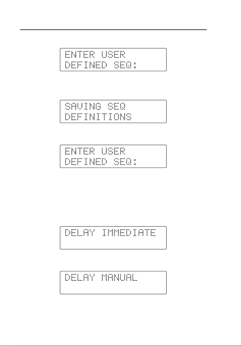
4. Enter the time delay after the command in hours, minutes, seconds (HH
MM SS) format. For example:
5. Press T, even if the delay type is DEFINE TIMING IMMEDIATE or
DEFINE TIMING MANUAL. The display shows:
6. Press R or S to scroll through the menu to define more commands,
or to end the command definition and define the ACTION AFTER LAST
COMMAND, as shown below:
7. Press T at the DEFINE MORE COMMANDS menu to define the next
command and its corresponding delay. The display then returns to:
8. Alternatively, press T at the ACTION AFTER LAST COMMAND
menu to end the defining of commands for that user sequence and define
the ACTION AFTER LAST CMD. The display then shows the menu:
3-6
Page 33

Programming User Sequences
Defining User Sequences
9. Press S or R to scroll through the menu. The display then shows:
10. Press T at ACTION AFTER LAST CMD - STOP. The Controller then
defines the action after executing the last command in the sequence as
STOP; the execution stops. Alternatively, if you press T at ACTION
AFTER LAST CMD - RPT, the Controller defines the action after
executing the last command in the sequence as REPEAT; the sequence
execution repeats again from the first command in the sequence. The
display then shows:
3
Viewing and Editing User Sequences
1. Press T at the VIEW/EDIT menu. The display then shows:
2. Press T to confirm. The display changes to:
3-7
Page 34

HHC3
Users Manual
3. Press the first digit of the user-programmed dual keys (from K B to
L F). The display shows:
4. Press the second digit of the user-programmed dual keys. The display
shows:
5. Press T to select that user-programmed dual keys, which then displays
the command defined for those keys. For example, if you pressed the dual
keys K B, the display changes to:
Press R or S to scroll for any of the commands defined for that key.
6. Press T to select any of the commands, and the display changes to:
3-8
Page 35

Programming User Sequences
Defining User Sequences
7. Press R or S to scroll through the menu for the following options:
Deleting Commands
1. Press T to select one of the options. If you press T when DELETE
COMMAND displays, the Controller deletes the selected command, and
the display shows:
3
2. Press T; the display now shows the next existing command defined for
that sequence. For example:
From here forward, the same procedure follows with the options for
deleting or editing the command if you press T.
3-9
Page 36

HHC3
Users Manual
Editing Commands
1. If you press T when EDIT COMMAND displays, you can edit the
selected command; the display then shows:
2. Press the first digit (from B to J) of the chosen two-digit waveform.
3. Press the second digit (from B to P) of the chosen two-digit
waveform. If the two-digit waveform number just entered is an immediate
command, the display shows the corresponding command description. For
example, if you press the dual keys C B, the display shows:
4. Press T to edit one of the selected user commands. The display changes
to:
3-10
Page 37

Programming User Sequences
Defining User Sequences
3
After two seconds, the display changes to display the type of delay defined
previously for that command. If DELAY was IMMEDIATE, the display
shows:
If DELAY was MANUAL, the display shows:
If you defined the Delay as Timed, the display shows:
5. If the two-digit waveform number just entered is a stepped command, the
display shows the corresponding command description of the default
selection value along with the arrows. For example, if you press the dual
keys D P, the display shows:
6. Press R or S to select one of the values, and then press T. The
display then shows this menu:
3-11
Page 38

HHC3
Users Manual
7. Press S to scroll through the menu:
8. At this point, two choices are available. If you press T at the DEFINE
AS IMMEDIATE menu, the Controller defines the new user sequence as
an immediate command with the selected value of the stepped command.
Alternatively, if you press T at the DEFINE AS STEPPED menu, the
Controller defines the new user sequence as a stepped command. The
display then shows:
After two seconds, the display changes to show the type of delay defined
previously for that command.
If the defined DELAY was IMMEDIATE, the display shows:
If the defined DELAY was MANUAL, the display shows:
If you defined the DELAY as TIMED, the display shows:
3-12
Page 39

Programming User Sequences
Defining User Sequences
9. Press T to proceed with the next display, which shows:
3
10. Press S to scroll through the menu for the next option, which displays:
11. Press T to select one of the options. If you press T at EDIT
DELAY, the display changes to:
12. Press R or S to scroll through the delay selection menu. Press S,
and the display changes to:
13. Press S, and the display changes to:
3-13
Page 40

HHC3
Users Manual
14. At this point, you can select any of these types of delay and press T. If
the delay type selected is DEFINE TIMING DELAY, the display changes
to:
15. Enter the time delay after the command in hours, minutes, seconds (HH
MM SS) format. For example:
16. Press T after you define the delay. The display changes to:
After 2 seconds (if the defined ACTION was STOP), the display shows:
If you press T at the SKIP EDIT DELAY option, the Controller also
shows the following display:
3-14
Page 41

Programming User Sequences
Defining User Sequences
Alternatively, if the defined Action was REPEAT, the display shows:
17. Press T to proceed with the next display, which shows:
18. Press S to scroll the menu for the next option, which displays:
19. Press T to select the option. If you press T at EDIT ACTION
AFTER LAST CMD, the display changes to:
3
20. Press S to scroll to the next option, which displays:
21. Press T to select any of the above options. The display changes to:
3-15
Page 42
HHC3
Users Manual
After two seconds, the display returns to:
22. If you press T at SKIP ACTION AFTER LAST CMD, the display
changes to:
After two seconds, the display returns to:
Skipping Command Editing
If you press T at SKIP EDIT COMMAND, you cannot edit the selected
command. However, you can edit the corresponding defined delay for that
command with the new type of delay. If the defined DELAY was
IMMEDIATE, the display shows:
If the defined DELAY was MANUAL, the display shows:
3-16
Page 43

Programming User Sequences
Defining User Sequences
3
If you defined the DELAY as TIMED, the display shows:
1. Press T to proceed with the next display, which shows:
2. Press S to scroll through the menu for the next option, which displays:
3. Press T to select one of the options. If you press T at EDIT
DELAY, the display changes to:
4. Press R or S to scroll through the menu for selecting the type of
delay. Press S, and the display changes to:
3-17
Page 44

HHC3
Users Manual
5. Press S, and the display changes to:
6. At this point, you can select any of these types of delay and press T. If
the delay type selected is DEFINE TIMING DELAY, the display changes
to:
7. Enter the time delay to execute after the command in hours, minutes,
seconds (HH MM SS) format. For example:
8. Press T after you define the delay. The display changes to display the
type of action after the last command that was previously defined for that
command.
After 2 seconds (if the defined Action was STOP), the display shows:
If you pressed T at SKIP EDIT DELAY, the Controller also shows the
above display.
3-18
Page 45

Programming User Sequences
Defining User Sequences
3
Alternatively, if the defined Action was REPEAT, the display shows:
9. Press T to proceed with the next display, which shows:
10. Press S to scroll through the menu for the next option, which displays:
11. Press T to select the option. If you press T at EDIT ACTION
AFTER LAST CMD, the display changes to:
12. Press S to scroll to the next option, which displays:
13. Press T to select any of the above options. The display changes to:
3-19
Page 46
HHC3
Users Manual
After two seconds, the display returns to:
14. If you press T at SKIP ACTION AFTER LAST CMD, the display
changes to:
After two seconds, the display returns to:
Adding Commands
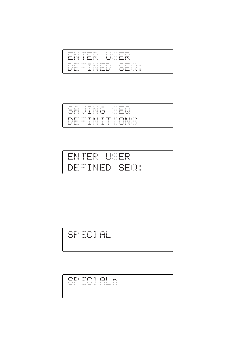
If you pressed T at ADD COMMAND, the Controller adds a new command
at the end of all the commands in the sequence. You will be defining the new
command and the corresponding delay. The display shows:
1. Press the first digit (from B to J) of the chosen two-digit waveform.
2. Press the second digit (from B to P) of the chosen two-digit
waveform. If the two-digit waveform number just entered is an immediate
3-20
Page 47
Programming User Sequences
Defining User Sequences
3
command, the display shows the corresponding command description. For
example, if you press the dual keys C B, the display changes to:
3. Press T to add the command for the existing user sequence. The display
changes to:
After two seconds, the display changes to:
4. If the two-digit waveform number just entered is a stepped command, the
display shows the corresponding command description of the default
selection value along with the arrows. For example, if you pressed the dual
keys D P, the display changes to:
5. Press R or S to select one of the values, and then press T. The
display then shows this menu:
3-21
Page 48

HHC3
Users Manual
6. Press S to scroll through the menu:
7. At this point, two choices are available. If you pressed T at the
DEFINE AS IMMEDIATE menu, the Controller defines the command as
a stepped command and adds it to the existing sequence. Alternatively, if
you pressed T at the DEFINE AS STEPPED menu, the Controller
defines the new user sequence as a stepped command. The display then
shows:
After two seconds, the display changes to:
8. Press R or S to scroll through the menu for selecting the type of
delay. Press S, and the display changes to:
9. At this point, you can select any of these types of delay and press T. If
the delay type selected is DEFINE TIMING DELAY, the display changes
to:
3-22
Page 49

Programming User Sequences
Defining User Sequences
10. Enter the time delay after the command in hours, minutes, seconds (HH
MM SS) format. For example:
11. Press T after you define the delay. The display returns to the initial
display, which again repeats in the same way as for other user-defined
sequences. The display shows:
After 2 seconds, the display returns to the initial screen:
3
Deleting All User Sequences
1. Press T to select DELETE ALL, which deletes the commands defined
for all the user sequences. Then the Controller display shows:
2. If you press T at this display, the Controller deletes all the user
sequences and shows:
3-23
Page 50

HHC3
Users Manual
3. Press T to return to the Start-up mode, which displays:
Running a Factory or User Sequence
Invoking Factory or User sequences resembles dual-key operation.
There are 13 Factory sequences, corresponding to the dual keys from
L G to M D. There can be up to 20 User sequences, corresponding
to the dual keys from K B to L F.
These sequences consist of a set of commands that execute one after the other
in the order defined by the user, with an intermediate delay between
commands. These delays can be immediate (with a default minimum delay of 2
seconds), timed (where the user defines the specific time), or manual (where
you have to use S to proceed to the next command in the sequence.)
If the delay is immediate, the Controller executes the command, waits for the
default 2-second delay, and automatically proceeds to the next command. If the
delay is timed, the Controller executes the command, waits for the defined
delay, and proceeds to the next command automatically.
If you defined the timed delay for an immediate command, the Controller
displays the corresponding command description. After two seconds, the
Controller shows the following display until the defined delay elapses:
3-24
Page 51

Programming User Sequences
Running a Factory or User Sequence
If the delay type is manual, the Controller sends the command to the simulator
immediately. The Controller displays the command description. After two
seconds, the display shows:
Press S to exit this command and proceed with the next command in the
sequence.
For stepped commands, you can scroll through the stepped command selection
values and press T to execute that command. At this stage, you can press
R or S to select any other selection value and execute or you can press
and hold S to exit this stepped command and proceed with the next
command in the sequence.
At the end of the sequence execution, if you defined the action after last
command as STOP, the Controller displays:
3
Alternatively, if you defined the action after last command as REPEAT, the
Controller continues executing the same sequence from the beginning.
3-25
Page 52

HHC3
Users Manual
3-26 4-1
Page 53

Chapter 4
Using the Application Software
Introduction
Use the HHC-Utility software to upload and download user-defined sequences
from and to a PC. Upload gets the user-defined sequences defined in the
Controller and saves them in a text file on the PC. Download sends the userdefined sequences saved in a text file on the PC to the Controller.
Installing the HHC-Utility Software
Note
Install the software prior to connecting the hardware.
Select Start | Run | SetUp.exe to install the HHC-Utility software. Soon after
the installation starts, click the Next > button; a window appears as follows:
ems027s.bmp
Page 54

HHC3
Users Manual
1. Enter the user name and the organization name. Next, click “Anyone who
uses this computer (all users)” or “Only for me.” Then click the Next >
button. The following window now appears:
ems028s.bmp
4-2
Page 55

Using the Application Software
Installing the HHC-Utility Software
2. Next, select the path for installing the application on the PC. The default
path is C:\Program Files\FLUKE\HHC-Utility Software. To proceed,
click the Next > button. The software displays all the details you require
for installation as follows:
ems029s.bmp
4
3. Click the Next > button in the preceding window: installation of the HHC
– PC Utility software will now proceed.
4-3
Page 56

HHC3
Users Manual
4. When installation is complete, a window appears as follows:
ems031s.bmp
5. Uncheck the box if you do not want to launch the application immediately.
Then click the Finish button.
6. To run the application, go to Start → Programs → FLUKE →
HHC-Utility Software and select HHC-Utility Software. A short cut for
the executable file will appear on the desktop with the name "HHC-Utility
Software." Run the application by double clicking on the short cut.
7. To uninstall the software, go to Start → Programs→ FLUKE →
HHC-Utility Software and select Uninstall HHC-Utility Software.
4-4
Page 57

Using the Application Software
Connecting the Controller to a PC
4
Connecting the Controller to a PC
Note
Install the software prior to connecting the hardware.
Connect the Controller to a PC using the MPS450/Marq III Serial Interface
Cable (PN 2702279) and the Serial Adapter Cable (2702287.) Refer to Figure
4-1 for a view of Controller-to-PC connections.
PC
HHC3
Figure 4-1. Connecting the Controller to a PC
4-5
ems033f.eps
Page 58

HHC3
Users Manual
Testing the Connection
Soon after the application starts, the HHC–Utility software displays:
ems006s.bmp
Launch the HHC-Utility software and select the Serial Port or USB Port to
which the Controller is connected.
Select the Serial Port radio button if the Controller connects to the PC via an
RS232 cable, and then select the appropriate COM Port. Select USB if the
Controller connects to the PC via a USB-to-RS-232 converter cable. Select the
appropriate COM Port.
4-6
Page 59

Using the Application Software
Downloading User Sequences
Click the CONNECTION button. If the connection is successful, the software
enables all controls on the PC Utility screen except the CONNECTION
button and the Communication Port section, as shown below:
4
ems007s.bmp
Downloading User Sequences
During this process, the text files from the PC will automatically download
into the Controller. The DOWNLOAD button and other controls go active
after the connection between the Controller and the PC is successful.
Follow the procedure mentioned earlier to successfully connect and
communicate between the Controller and the PC.
Select the type of simulator to receive a text file download. The text file
contains the user-defined sequences.
Double click on the required directory; this in turn will display the available
text files of that directory in a file list box.
4-7
Page 60
HHC3
Users Manual
You can select a text file from the list box by clicking on the corresponding
text file. The selected file appears in the text box.
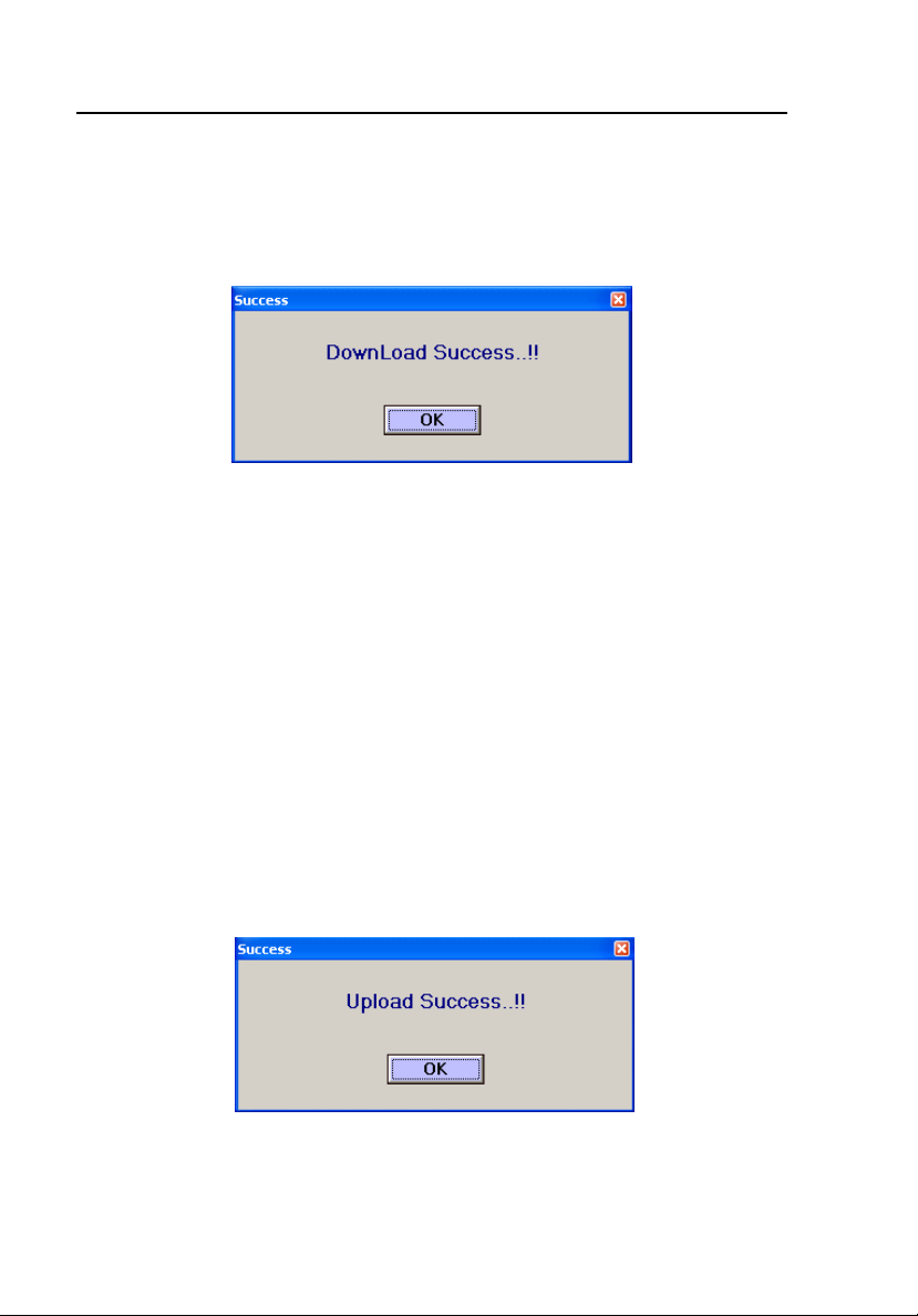
Then click the DOWNLOAD button. The following message appears if the
download process is successful:
ems008s.bmp
Uploading User Sequences
During this process, user-defined sequences upload from the Controller into
the PC.
Follow the procedure mentioned earlier to connect the Controller and the PC.
Select the type of simulator to upload the user-defined sequences.
Click the UPLOAD button. If the PC receives all the user-defined sequences,
an Upload success message appears as follows:
Note
The PC creates the folder “HHC Commands Back Up” in the
application folder. Text file name will contain the simulator name.
ems009s.bmp
The received data automatically saves to a folder named “HHC Commands
Back Up.”
4-8
Page 61

Using the Application Software
Uploading User Sequences
Note
If you upload and download the same file several times between the
PC and the attached HHC3, the program will create duplicate files.
While this condition does not cause any damage to the program, it
makes it difficult to both locate the original files and easily manage
the required files.
To delete duplicate files from the HHC3 Program installed on your PC, you
must directly access the files via the My Computer icon. To perform this task,
open the HHC-Utility software and proceed as follows:
1. Double-click on the displayed folder: HHC Commands Back Up
2. Double click on and then copy the entire displayed file path in the above
window. A default setting example is as follows:
c:\Program Files\FLUKE\HHC - Utility Software\HHC Commands
Back Up
3. Double click on the My Computer icon on your PC screen.
4. Copy the file on to the Address line and then click Go.
5. Highlight and then delete the duplicated files created by the multiple
uploads and downloads.
4
6. Return to the HHC-Utility software.
7. Refresh the displayed "Select Data Base File" by double clicking the
above "HHC- Utility Folder" and then return to the HHC Commands Back
Up folder by double clicking on it. The deleted files are now removed
from the list.
4-9
Page 62

HHC3
Users Manual
Error Messages
If you have not selected and clicked one of the ports on the CONNECTION
button, an error message appears as follows:
ems010s.bmp
Click the OK button and select a serial or USB port.
A warning message appears as follows soon after USB port selection.
ems011s.bmp
Click the OK button and select the COM port allocated for USB.
If you have clicked the CONNECTION button but have not selected a COM
port, an error message appears as follows:
ems012s.bmp
Click the OK button and select the COM port.
4-10
Page 63

Using the Application Software
Error Messages
The last available COM port will be the port allocated to USB. If you have not
selected the last port, an error message appears as follows:
4
Click the OK button and select the last COM port.
If the connection between the Controller and the PC is not successful, a
message appears on the PC Utility screen as follows:
Click the OK button, restart the Controller, select the appropriate COM port,
and click the CONNECTION button again.
If you have clicked the DOWNLOAD button but have not selected the
required parameters, an error message appears as follows:
ems013s.bmp
ems014s.bmp
Click the OK button and select the required parameters.
4-11
ems015s.bmp
Page 64

HHC3
Users Manual
If there is any problem with accessing the user-selected port, an error message
appears as follows:
ems016s.bmp
Click the OK button and select a valid COM port.
If there is any mismatch between the text file and the simulator selected, an
error message appears as follows:
ems017s.bmp
The same error message appears if the received data does not match with the
simulator selected. Click the OK button and try uploading and downloading
files again.
If there is any error in accessing the user-selected text file, a message appears
as follows:
Click the OK button and select a valid file.
4-12
ems018s.bmp
Page 65

Using the Application Software
Error Messages
If the “Number of packets“ value read from the file or port is more than the
“Maximum packets” or equal to zero, an error message appears as follows:
4
Click the OK button and try uploading and downloading files again.
If the software does not receive a positive acknowledgement for the download
or upload process initialization, an error message appears as follows:
Click the OK button and try uploading and downloading files again.
If the software does not receive a positive acknowledgement for the packet
transmitted during download, an error message appears as follows:
ems019s.bmp
ems020s.bmp
Click the OK button and try downloading again.
4-13
ems021s.bmp
Page 66

HHC3
Users Manual
If you have clicked the UPLOAD button but have not selected the required
parameters, an error message appears as follows:
ems022s.bmp
Click the OK button and select the required parameters.
If the software does not receive the “number of packets” value or a complete
packet within the given time, an error message appears as follows:
ems023s.bmp
Click the OK button and try uploading again.
If data read from the port is not of the valid format, an error message appears
as follows:
Click the OK button and try uploading again.
4-14
ems024s.bmp
Page 67

Using the Application Software
Error Messages
If the Packet Size received is more than the “Maximum packet Size” or equal
to zero, an error message appears as follows:
4
Click the OK button and try uploading again.
If there is a checksum error even after re-reception of the same packet twice
from the Controller, an error message appears as follows:
Click the OK button and try uploading again.
ems025s.bmp
ems026s.bmp
4-15
Page 68

HHC3
Users Manual
4-16
Page 69

Appendix A
Dual-Key Commands
Introduction
BP1, BP2, BP3, or BP4 are set to normal values by sending command P1LV,
P2ART, P3PA, or P4RV, respectively, for all three simulators. Follow this
with one of the commands shown in Table A-1.
Table A-1. Dual-Key Commands
Keys Command Description medSim 300B MPS450 Marq III
B
B
B
C
NSR
NSR Rate
Normal sinus ECG at 30 BPM NSB30 (Step) NSR30 (Step) NSR30 (Step)
Normal sinus ECG at 40 BPM NSR40 NSR40
Normal sinus ECG at 45 BPM NSR45 NSR45
Normal sinus ECG at 60 BPM NSB60 NSR60 NSR60
Normal sinus ECG at 80 BPM NSB80 NSR80 NSR80
Normal sinus ECG at 90 BPM NSR90 NSR90
Normal sinus ECG at 100 BPM NSR100 NSR100
Normal sinus ECG at 120 BPM NSB120 NSR120 NSR120
Normal sinus ECG at 140 BPM NSR140 NSR140
Normal sinus ECG at 160 BPM NSB160 NSR160 NSR160
Normal sinus ECG at 180 BPM NSR180 NSR180
Normal sinus ECG at 200 BPM NSB200 NSR200 NSR200
Normal sinus ECG at 220 BPM NSR220 NSR220
Normal sinus ECG at 240 BPM NSB240 NSR240 NSR240
Normal sinus ECG at 260 BPM NSR260 NSR260
Normal sinus ECG at 280 BPM NSR280 NSR280
Normal sinus ECG at 300 BPM NSB300 NSR300 NSR300
NSR
NSR
NSR
A-1
Page 70

HHC3
Users Manual
Table A-1. Dual-Key Commands (cont.)
Keys Command Description medSim 300B MPS450 Marq III
B
D
J
B
ECG Amplitude
ECG Amplitude 0.05 mV NSA0.05 (Step) NSA0.05 (Step) NSA0.05 (Step)
ECG Amplitude 0.10 mV NSA0.10 NSA0.10 NSA0.10
ECG Amplitude 0.15 mV NSA0.15 NSA0.15 NSA0.15
ECG Amplitude 0.20 mV NSA0.20 NSA0.20 NSA0.20
ECG Amplitude 0.25 mV NSA0.25 NSA0.25 NSA0.25
ECG Amplitude 0.30 mV NSA0.30 NSA0.30 NSA0.30
ECG Amplitude 0.35 mV NSA0.35 NSA0.35 NSA0.35
ECG Amplitude 0.40 mV NSA0.40 NSA0.40 NSA0.40
ECG Amplitude 0.45 mV NSA0.45 NSA0.45 NSA0.45
ECG Amplitude 0.50 mV NSA0.50 NSA0.50 NSA0.50
ECG Amplitude 0.75 mV NSA0.75
ECG Amplitude 1.00 mV NSA1.00 NSA1.00 NSA1.00
ECG Amplitude 1.25 mV NSA1.25
ECG Amplitude 1.50 mV NSA1.50 NSA1.50 NSA1.50
ECG Amplitude 1.75 mV NSA1.75
ECG Amplitude 2.00 mV NSA2.00 NSA2.00 NSA2.00
ECG Amplitude 2.25 mV NSA2.25
ECG Amplitude 2.50 mV NSA2.50 NSA2.50 NSA2.50
ECG Amplitude 2.75 mV NSA2.75
ECG Amplitude 3.00 mV NSA3.00 NSA3.00 NSA3.00
ECG Amplitude 3.25 mV NSA3.25
ECG Amplitude 3.50 mV NSA3.50 NSA3.50 NSA3.50
ECG Amplitude 3.75 mV NSA3.75
ECG Amplitude 4.00 mV NSA4.00 NSA4.00 NSA4.00
ECG Amplitude 4.25 mV NSA4.25
ECG Amplitude 4.50 mV NSA4.50 NSA4.50 NSA4.50
ECG Amplitude 4.75 mV NSA4.75
ECG Amplitude 5.00 mV NSA5.00 NSA5.00 NSA5.00
ECG Amplitude 5.25 mV NSA5.25
ECG Amplitude 5.50 mV NSA5.50 NSA5.50 NSA5.50
Patient type
Set patient type to Adult ADULT (Step) ADULT (Step)
Set patient type to Pediatric PEDS PEDS
A-2
Page 71

Dual-Key Commands
Introduction
Table A-1. Dual-Key Commands (cont.)
Keys Command Description medSim 300B MPS450 Marq III
B
E
B
F
B
G
B
S-T Segment deviation
S-T Segment deviation -0.8 mV STD-0.8 (Step) STD-0.8
S-T Segment deviation -0.7 mV STD-0.7 STD-0.7 STD-0.7
S-T Segment deviation -0.6 mV STD-0.6 STD-0.6 STD-0.6
S-T Segment deviation -0.5 mV STD-0.5 STD-0.5 STD-0.5
S-T Segment deviation -0.4 mV STD-0.4 STD-0.4 STD-0.4
S-T Segment deviation -0.3 mV STD-0.3 STD-0.3 STD-0.3
S-T Segment deviation -0.2 mV STD-0.2 STD-0.2 STD-0.2
S-T Segment deviation -0.1 mV STD-0.1 STD-0.1 STD-0.1
S-T Segment deviation -0.05 mV STD-0.05 STD-0.05 STD-0.05
S-T Segment deviation 0.0 mV STD0 STD0.0 STD0.0
S-T Segment deviation +0.05 mV STD+0.05 STD+0.05 STD+0.05
S-T Segment deviation +0.1 mV STD+0.1 STD+0.1 STD+0.1
S-T Segment deviation +0.2 mV STD+0.2 STD+0.2 STD+0.2
S-T Segment deviation +0.3 mV STD+0.3 STD+0.3 STD+0.3
S-T Segment deviation +0.4 mV STD+0.4 STD+0.4 STD+0.4
S-T Segment deviation +0.5 mV STD+0.5 STD+0.5 STD+0.5
S-T Segment deviation +0.6 mV STD+0.6 STD+0.6 STD+0.6
S-T Segment deviation +0.7 mV STD+0.7 STD+0.7 STD+0.7
S-T Segment deviation +0.8 mV STD+0.8 STD+0.8 STD+0.8
Axis deviation
Normal AXNRM (Step)
Horizontal AXHRZ
Vertical AXVER
Neonatal ECG
Neonatal ECG OFF NEOOFF
Neonatal ECG ON NEOON
(Immed)
(Immed)
(Step)
STD-0.8 (Step)
A
H
A-3
Page 72

HHC3
Users Manual
Table A-1. Dual-Key Commands (cont.)
Keys Command Description medSim 300B MPS450 Marq III
B
I
B
J
Performance waveform
Zero o/p performance waveform ZERO (Step)
Pulse 4 sec performance waveform PUL
2 Hz square performance wave
0.125 Hz square performance wave
2 Hz triangle performance wave
2.5 Hz triangle performance wave
30 BPM pulse performance waveform
60 BPM pulse performance waveform
0.05 Hz sine performance wave
0.5 Hz sine performance wave
1 Hz sine performance wave
5 Hz sine performance wave
10 Hz sine performance wave
25 Hz sine performance wave
30 Hz sine performance wave
40 Hz sine performance wave
50 Hz sine performance wave
60 Hz sine performance wave
100 Hz sine performance wave
R wave detection width
R wave detection width 8 ms RW8 (Step)
R wave detection width 12 ms RW12
R wave detection width 20 ms RW20
R wave detection width 40 ms RW40
R wave detection width 80 ms RW80
R wave detection width 100 ms
R wave detection width 120 ms
R wave detection width 140 ms
R wave detection width 160 ms
R wave detection width 200 ms
SQU
TRI
SIN0.05
SIN0.5
SIN1
SIN10
SIN25
SIN30
SIN40
SIN50
SIN60
SIN100
RW100
RW120
RW140
RW160
RW200
SQU2 (Step) SQU2 (Step)
SQU0.125 SQU0.125
TRI2 TRI2
TRI2.5 TRI2.5
PUL30 PUL30
PUL60 PUL60
SIN0.5 SIN0.5
SIN5 SIN5
SIN10 SIN10
SIN40 SIN40
SIN50 SIN50
SIN60 SIN60
SIN100 SIN100
A-4
Page 73

Dual-Key Commands
Introduction
Table A-1. Dual-Key Commands (cont.)
Keys Command Description medSim 300B MPS450 Marq III
R wave detection width
J
I
B
R wave detection width 8 ms RWW8 (Step) RWW8 (Step)
R wave detection width 10 ms RWW10 RWW10
R wave detection width 12 ms RWW12 RWW12
R wave detection width 20 ms RWW20 RWW20
R wave detection width 30 ms RWW30 RWW30
R wave detection width 40 ms RWW40 RWW40
R wave detection width 50 ms RWW50 RWW50
R wave detection width 60 ms RWW60 RWW60
R wave detection width 70 ms RWW70 RWW70
R wave detection width 80 ms RWW80 RWW80
R wave detection width 90 ms RWW90 RWW90
R wave detection width 100 ms RWW100 RWW100
R wave detection width 110 ms RWW110 RWW110
R wave detection width 120 ms RWW120 RWW120
R wave detection width 130 ms RWW130 RWW130
R wave detection width 140 ms RWW140 RWW140
R wave detection width 150 ms RWW150 RWW150
R wave detection width 160 ms RWW160 RWW160
R wave detection width 170 ms RWW170 RWW170
R wave detection width 180 ms RWW180 RWW180
R wave detection width 190 ms RWW190 RWW190
R wave detection width 200 ms RWW200 RWW200
Supra ventricular Arrhythmias
Atrial Fibrillation, coarse AF1 (Immed) AF1 (Immed) AF1 (Immed)
A
K
B
L
B
M
B
N
Atrial Fibrillation, fine AF2 (Immed) AF2 (Immed) AF2 (Immed)
Atrial Flutter AFL (Immed) AFL (Immed) AFL (Immed)
Sinus Arrhythmia SINA (Immed) SINA (Immed) SINA (Immed)
A-5
Page 74

HHC3
Users Manual
Table A-1. Dual-Key Commands (cont.)
Keys Command Description medSim 300B MPS450 Marq III
B
Missed Beat at 80 BPM MB80 (Immed) MB80 (Immed) MB80 (Immed)
O
B
Missed Beat at 120 BPM MB120
(Immed)
P
C
Paroxysmal Atrial Tachycardia PAT (Immed) PAT (Immed) PAT (Immed)
B
C
Nodal rhythm NOD (Immed) NOD (Immed) NOD (Immed)
C
C
Supra ventricular tachycardia SVT (Immed) SVT (Immed) SVT (Immed)
D
Premature contraction
C
Premature Atrial contraction PAC (Immed) PAC PAC
E
C
Premature nodal contraction PNC (Immed) PNC (Immed) PNC (Immed)
F
C
G
C
H
A-6
Premature ventricular contraction left,
standard
Premature ventricular contraction left,
early
Premature ventricular contraction left,
R onT
Premature ventricular contraction
right, standard
Premature ventricular contraction
right, early
Premature ventricular contraction
right, R onT
Multi focal PVCs (medSim 300B)
Multi focal PVCs 1 (MPS 450)
PVC (Immed) PVC1S (Step) PVC1S (Step)
PVC1E PVC1E
PVC1R PVC1R
PVC2S PVC2S
PVC2E PVC2E
PVC2R PVC2R
MF1 (Step) MF (Immed) MF (Immed)
Page 75

Dual-Key Commands
Introduction
Table A-1. Dual-Key Commands (cont.)
Keys Command Description medSim 300B MPS450 Marq III
C
Multi focal PVCs 2 MF2
A
I
C
J
C
Multi focal PVCs 3
MF3
Ventricular Arrhythmias
Ventricular rhythm VNT (Immed)
K
C
Ventricular Tachycardia VTC (Immed) VTC (Immed) VTC (Immed)
L
C
M
C
Ventricular Fibrillation VFB1 (Immed) VFB1 (Step) VFB1 (Step)
VFB2 VFB2
Atrial Tachycardia ATC (Immed) ATC (Immed)
N
C
Electromotive disassociation EMD (Immed)
O
C
P
D
B
D
C
D
D
D
E
Asystole ASY (Immed) ASY (Immed) ASY (Immed)
Bigeminy BIG (Immed) BIG (Immed) BIG (Immed)
Trigeminy TRG (Immed) TRG (Immed) TRG (Immed)
Pair of PVCs PAIR (Immed) PAIR (Immed) PAIR (Immed)
5 PVCs RUN5 (Immed) RUN5
(Immed)
RUN5 (Immed)
A-7
Page 76

HHC3
Users Manual
Table A-1. Dual-Key Commands (cont.)
Keys Command Description medSim 300B MPS450 Marq III
D
F
D
11 PVCs RUN11 (Immed) RUN11 (Step) RUN11 (Step)
PVCs 6 per minute PVC6 PVC6
PVCs 12 per minute PVC12 PVC12
PVCs 24 per minute PVC24 PVC24
Frequent multifocal PVCs FMF FMF
Conduction Arrhythmias
First degree A-V block 1DB (Immed) 1DB (Immed) 1DB (Immed)
G
D
Second degree A-V block, type1 2DB1 (Immed) 2DB1 (Immed) 2DB1 (Immed)
H
D
Second degree A-V block, type2 2DB2 (Immed)
I
D
Third degree A-V block 3DB (Immed) 3DB (Immed) 3DB (Immed)
J
D
Right bundle branch block RBB (Immed) RBB (Immed) RBB (Immed)
K
D
L
D
M
D
N
A-8
Left bundle branch block LBB (Immed) LBB (Immed) LBB (Immed)
PVC Parameters PVC Type
PVC Parameters PVC Type 1 PVCT1 (Step)
PVC Parameters PVC Type 2 PVCT2
PVC Parameters PVC Type 3 PVCT3
PVC Parameters PVC Type 4 PVCT4
PVC Parameters PVC Timing
PVC Timing R on T wave PVCR (Step)
PVC Timing Early PVC PVCE
PVC Timing Standard PVC PVCS
Page 77

Dual-Key Commands
Introduction
Table A-1. Dual-Key Commands (cont.)
Keys Command Description medSim 300B MPS450 Marq III
PVC Parameters PVCs per minute
PVC Parameters PVC/MIN: 0 PVC0 (Step)
PVC Parameters PVC/MIN: 1 PVC1
PVC Parameters PVC/MIN: 2 PVC2
PVC Parameters PVC/MIN: 3 PVC3
D
O
D
P
PVC Parameters PVC/MIN: 4 PVC4
PVC Parameters PVC/MIN: 5 PVC5
PVC Parameters PVC/MIN: 6 PVC6
PVC Parameters PVC/MIN: 7 PVC7
PVC Parameters PVC/MIN: 8 PVC8
PVC Parameters PVC/MIN: 9 PVC9
PVC Parameters PVC/MIN: 10 PVC10
PVC Parameters PVC/MIN: 11 PVC11
PVC Parameters PVC/MIN: 12 PVC12
PVC Parameters PVC/MIN: 13 PVC13
PVC Parameters PVC/MIN: 14 PVC14
PVC Parameters PVC/MIN: 15 PVC15
PVC Parameters PVC/MIN: 16 PVC16
PVC Parameters PVC/MIN: 17 PVC17
PVC Parameters PVC/MIN: 18 PVC18
PVC Parameters PVC/MIN: 19 PVC19
PVC Parameters PVC/MIN: 20 PVC20
PVC Parameters PVC/MIN: 21 PVC21
PVC Parameters PVC/MIN: 22 PVC22
PVC Parameters PVC/MIN: 23 PVC23
PVC Parameters PVC/MIN: 24 PVC24
PVC Parameters PVC/MIN: 25 PVC25
Pacemaker wave
Atrial Pacer wave ATR (Step) ATR (Step)
Asynchronous at 75 BPM ASN (Step) ASN ASN
Demand 1 DM1 DFS DFS
Demand 2 DM2 DOS DOS
Atrial-ventricular sequential AVS AVS AVS
Non-capture pacer NCA NCA NCA
Non-function pacer NFU NFU NFU
A
A-9
Page 78

HHC3
Users Manual
Table A-1. Dual-Key Commands (cont.)
Keys Command Description medSim 300B MPS450 Marq III
E
B
Pacemaker atrial amplitude
Pacemaker atrial amplitude -700 mV AH-700 (Step)
Pacemaker atrial amplitude -500 mV AH-500
Pacemaker atrial amplitude -200 mV AH-200
Pacemaker atrial amplitude -100 mV AH-100
Pacemaker atrial amplitude -50 mV AH-50
Pacemaker atrial amplitude -20 mV AH-20
Pacemaker atrial amplitude -18 mV AH-18
Pacemaker atrial amplitude -16 mV AH-16
Pacemaker atrial amplitude -14 mV AH-14
Pacemaker atrial amplitude -12 mV AH-12
Pacemaker atrial amplitude -10 mV AH-10
Pacemaker atrial amplitude -8 mV AH-8
Pacemaker atrial amplitude -6 mV AH-6
Pacemaker atrial amplitude -4 mV AH-4
Pacemaker atrial amplitude -2 mV AH-2
Pacemaker atrial amplitude 0 mV AH0
Pacemaker atrial amplitude +1 mV
Pacemaker atrial amplitude +2 mV
Pacemaker atrial amplitude +4 mV
Pacemaker atrial amplitude +5 mV
Pacemaker atrial amplitude +6 mV
Pacemaker atrial amplitude +8 mV
Pacemaker atrial amplitude +10 mV
Pacemaker atrial amplitude +12 mV
Pacemaker atrial amplitude +14 mV
Pacemaker atrial amplitude +16 mV
Pacemaker atrial amplitude +18 mV
Pacemaker atrial amplitude +20 mV
Pacemaker atrial amplitude +50 mV
Pacemaker atrial amplitude +100 mV
Pacemaker atrial amplitude +200 mV
Pacemaker atrial amplitude +500 mV
Pacemaker atrial amplitude +700 mV
AH+2
AH+4
AH+6
AH+8
AH+10
AH+12
AH+14
AH+16
AH+18
AH+20
AH+50
AH+100
AH+200
AH+500
AH+700
PA1 (Step) PA1 (Step)
PA2 PA2
PA5 PA5
PA10 PA10
A-10
Page 79

Dual-Key Commands
Introduction
Table A-1. Dual-Key Commands (cont.)
Keys Command Description medSim 300B MPS450 Marq III
E
C
E
D
Pacemaker Atrial width
Pacemaker Atrial width 0.1 ms AW0.1 (Step) PW0.1 (Step) PW0.1 (Step)
Pacemaker Atrial width 0.2 ms AW0.2
Pacemaker Atrial width 0.5 ms AW0.5 PW0.5 PW0.5
Pacemaker Atrial width 1.0 ms AW1.0 PW1.0 PW1.0
Pacemaker Atrial width 1.5 ms PW1.5 PW1.5
Pacemaker Atrial width 2.0 ms AW2.0 PW2.0 PW2.0
Pacemaker ventricular amplitude
Pacemaker ventricular amplitude -700
mV
Pacemaker ventricular amplitude -500
mV
Pacemaker ventricular amplitude -200
mV
Pacemaker ventricular amplitude -100
mV
Pacemaker ventricular amplitude -50 mV VH-50
Pacemaker ventricular amplitude -20 mV VH-20
Pacemaker ventricular amplitude -18 mV VH-18
Pacemaker ventricular amplitude -16 mV VH-16
Pacemaker ventricular amplitude -14 mV VH-14
Pacemaker ventricular amplitude -12 mV VH-12
Pacemaker ventricular amplitude -10 mV VH-10
Pacemaker ventricular amplitude -8 mV VH-8
Pacemaker ventricular amplitude -6 mV VH-6
Pacemaker ventricular amplitude -4 mV VH-4
Pacemaker ventricular amplitude -2 mV VH-2
Pacemaker ventricular amplitude 0 mV VH0
Pacemaker ventricular amplitude +2 mV
Pacemaker ventricular amplitude +4 mV
VH-700 (Step)
VH-500
VH-200
VH-100
VH+2
VH+4
A
A-11
Page 80

HHC3
Users Manual
Keys Command Description medSim 300B MPS450 Marq III
E
E
E
Table A-1. Dual-Key Commands (cont.)
Pacemaker ventricular amplitude
+6 mV VH+6
Pacemaker ventricular amplitude
+8 mV VH+8
Pacemaker ventricular amplitude
+10 mV VH+10
Pacemaker ventricular amplitude
+12 mV
Pacemaker ventricular amplitude
+14 mV VH+14
Pacemaker ventricular amplitude
+16 mV VH+16
Pacemaker ventricular amplitude
+18 mV
Pacemaker ventricular amplitude
+20 mV VH+20
Pacemaker ventricular amplitude
+50 mV VH+50
Pacemaker ventricular amplitude
+100 mV
Pacemaker ventricular amplitude
+200 mV VH+200
Pacemaker ventricular amplitude
+500 mV VH+500
Pacemaker ventricular amplitude
+700 mV
Pacemaker ventricular width
Pacemaker ventricular width 0.1
ms VW0.1 (Step)
Pacemaker ventricular width 0.2
ms VW0.2
Pacemaker ventricular width 0.5
ms
Pacemaker ventricular width 1.0
ms VW1.0
Pacemaker ventricular width 2.0
ms VW2.0
Premature beat
Insert PVC IPVC (Immed)
VH+12
VH+18
VH+100
VH+700
VW0.5
F
A-12
Page 81

Dual-Key Commands
Introduction
A
Keys Command Description medSim 300B MPS450 Marq III
E
Insert PAC IPAC (Immed)
Table A-1. Dual-Key Commands (cont.)
G
E
Insert PNC IPNC (Immed)
H
E
I
E
J
J
C
E
K
Respiration
Respiration waveform normal RNRM (Step)
Respiration waveform ventilator
assisted
Delta impedance (Ohms)
delta impedance (Ohms) 0.0 RO0.0 (Step)
delta impedance (Ohms) 0.1 RO0.1
delta impedance (Ohms) 0.2 RO0.2
delta impedance (Ohms) 0.5 RO0.5
delta impedance (Ohms) 1.0 RO1.0
delta impedance (Ohms) 3.0 RO3.0
Respiration baseline impedance
Baseline impedance 500 ohms RB500 (Step) RB500 (Step)
Baseline impedance 1000 ohms RB1000 RB1000
Baseline impedance 1500 ohms RB1500 RB1500
Baseline impedance 2000 ohms RB2000 RB2000
Store Baseline impedance 500 ohms
Store Baseline impedance 1000 ohms
Store Baseline impedance 1500 ohms
Store Baseline impedance 2000 ohms
Store respiration base RBSTORE RBSTORE
Respiration rate
Respiration rate 0 BrPM RR0 (Step) RR0 (Step)
Respiration rate 15 BrPM RR15 (Step) RR15 RR15
Respiration rate 20 BrPM RR20 RR20 RR20
Respiration rate 30 BrPM RR30 RR30 RR30
Respiration rate 40 BrPM RR40 RR40 RR40
Respiration rate 60 BrPM RR60 RR60 RR60
Respiration rate 80 BrPM RR80 RR80
RVNT
RB500,
RBSTORE
RB1000,
RBSTORE
RB1500,
RBSTORE
RB2000,
RBSTORE
RB500,
RBSTORE
RB1000,
RBSTORE
RB1500,
RBSTORE
RB2000,
RBSTORE
A-13
Page 82

HHC3
Users Manual
Table A-1. Dual-Key Commands (cont.)
Keys Command Description medSim 300B MPS450 Marq III
J
D
E
L
E
M
E
N
E
Respiration rate 100 BrPM RR100 RR100
Respiration rate 120 BrPM RR120 RR120 RR120
Respiration Amplitude
Respiration Amplitude 0.2 ohms RO0.2 (Step) RO0.2 (Step)
Respiration Amplitude 0.5 ohms RO0.5 RO0.5
Respiration Amplitude 1.0 ohms RO1.0 RO1.0
Respiration Amplitude 3.0 ohms RO3.0 RO3.0
Respiration ratio
Respiration ratio 1/1
Respiration ratio 2/1
Respiration ratio 3/1
Respiration ratio 4/1
Respiration ratio 5/1
Respiration apnea
Respiration apnea OFF AOFF (Step) OFF (Step) OFF (Step)
Respiration apnea ON AON ON ON
start Respiration apnea at 12 secs A12 A12 A12
start Respiration apnea at 22 secs A22 A22
start Respiration apnea at 32 secs A32 A32 A32
Respiration baseline
Respiration baseline OFF SFTOFF (Step)
Respiration baseline shift positive
Respiration baseline shift negative R-SFT
Blood pressure channel 1
BP1 atmosphere
RAT1/1 (Step)
RAT2/1
RAT3/1
RAT4/1
RAT5/1
R+SFT
O
E
P
A-14
P1S0 (Immed)
BP1 waveform
atmosphere 0.0 mmHg
arterial 120/80 mmHg P1ART P1ART (Step) P1ART (Step)
P1S0 (Step)
Page 83

Dual-Key Commands
Introduction
Table A-1. Dual-Key Commands (cont.)
Keys Command Description medSim 300B MPS450 Marq III
BP1 radial art dynamic wave 120/80
Left ventricle 120/0 mmHg
F
B
Blood pressure channel 2
F
right ventricle 25/0 mmHg
Pulmonary artery 25/10 mmHg
Pulmonary artery wedge 10/2 mmHg
Central venous pressure 15/10 mmHg
BP1 static pressure
BP1 -10mm Hg P1S-10 (Step) P1S-10 (Step) P1S-10 (Step)
BP1 -5mm Hg P1S-5
BP1 0mm Hg P1S0 P1S0 P1S0
BP1 20mm Hg P1S20
BP1 40mm Hg P1S40
BP1 80mm Hg P1S80 P1S80 P1S80
BP1 100mm Hg P1S100
BP1 160mm Hg P1S160 P1S160
BP1 200mm Hg P1S200
BP1 240mm Hg P1S240 P1S240
BP1 250mm Hg P1S250
BP1 300mm Hg P1S300
BP1 320mm Hg P1S320 P1S320
BP1 400mm Hg P1S400 P1S400
BP2 atmosphere P2S0 (Immed)
P1LV
P1RV
P1PA
P1W
P1CVP
P1RART P1RART
P1LV P1LV
P1RV P1RV
A
C
F
D
BP2 waveform
atmosphere 0.0 mmHg
arterial 120/80 mmHg
BP2 radial art dynamic wave 120/80
Left ventricle 120/0 mmHg
right ventricle 25/0 mmHg
Pulmonary artery 25/10 mmHg
Pulmonary artery wedge 10/2 mmHg
BP2 left atrium dynamic wave 14/4
P2S0 (Step)
P2ART
P2LV
P2RV
P2PA
P2W
P2ART (Step) P2ART (Step)
P2RART P2RART
P2LV P2LV
P2RV P2RV
P2PA P2PA
P2W P2W
P2LA P2LA
A-15
Page 84

HHC3
Users Manual
Keys
F
E
F
Central venous pressure 15/10
mmHg
BP2 static pressure
BP2 -10mm Hg P2S-10 (Step) P2S-10 (Step) P2S-10 (Step)
BP2 -5mm Hg
BP2 0mm Hg
BP2 20mm Hg
BP2 40mm Hg
BP2 50mm Hg
BP2 80mm Hg
BP2 100mm Hg
BP2 150mm Hg
BP2 200mm Hg
BP2 240mm Hg
BP2 250mm Hg
BP2 300mm Hg
Blood pressure channel 3
BP3 atmosphere P3SO (Immed)
Table A-1. Dual-Key Commands (cont.)
Command Description medSim 300B MPS450 Marq III
P2CVP P2CVP P2CVP
P2S-5
P2S0
P2S20
P2S40
P2S80
P2S100
P2S200
P2S250
P2S300
P2S0 P2S0
P2S50 P2S50
P2S100 P2S100
P2S150 P2S150
P2S200 P2S200
P2S240 P2S240
F
F
G
A-16
BP3 waveform
atmosphere 0.0 mmHg P3SO (Step)
BP3 arterial dynamic wave 120/80 P3ART (Step) P3ART (Step)
BP3 radial art dynamic wave 120/80
BP3 left vent dynamic wave 120/0
BP3 right vent dynamic wave 25/0 P3RV P3RV P3RV
BP3 pulmonary art dynamic wave
25/10
BP3 pulmonary art wedge dynamic
wave 10/2
BP3 left atrium dynamic wave 14/4
BP3 right atrium CVP dynamic wave
15/10
P3PA P3PA P3PA
P3W P3W P3W
P3CVP P3CVP P3CVP
P3RART P3RART
P3LV P3LV
P3LA P3LA
Page 85

Dual-Key Commands
Introduction
Table A-1. Dual-Key Commands (cont.)
Keys Command Description medSim 300B MPS450 Marq III
F
H
F
I
F
BP3 static pressure
BP3 -10mm Hg
BP3 -5mm Hg
BP3 0mm Hg
BP3 5mm Hg
BP3 10mm Hg
BP3 20mm Hg
BP3 30mm Hg
BP3 40mm Hg P3S40 P3S40
BP3 60mm Hg P3S60 P3S60
BP3 80mm Hg P3S80 P3S80
BP3 100mm Hg P3S100 P3S100
BP3 Swan- Ganz procedure
Start STSG (Step)
Insert INS
Inflate INF
Deflate DEF
Remove REM
Blood pressure channel 4
BP4 atmosphere P4S0 (Immed)
P3S-10 (Step)
P3S-5
P3S0
P3S5
P3S10
P3S20
P3S30
P3S-5 (Step) P3S-5 (Step)
P3S0 P3S0
P3S20 P3S20
A
J
F
K
BP4 waveform
atmosphere 0.0 mmHg
arterial 120/80 mmHg
Left ventricle 120/0 mmHg
right ventricle 25/0 mmHg
Pulmonary artery 25/10 mmHg
Pulmonary artery wedge 10/2 mmHg
Triangle 30 mmHg
Triangle 300 mmHg
BP4 right atrium CVP dynamic wave
15/10
Start Swan-Ganz auto STSGAUTO STSGAUTO
P4S0 (Step)
P4ART
P4LV
P4RV
P4PA
P4W
P4T30
P4T300
P4CVP P4CVP
P4RV (Step) P4RV (Step)
P4PA P4PA
P4W P4W
A-17
Page 86

HHC3
Users Manual
Table A-1. Dual-Key Commands (cont.)
Keys Command Description medSim 300B MPS450 Marq III
F
L
F
M
F
Start Swan-Ganz manual STSG STSG
Insert INS INS
Inflate INF INF
Deflate DEF DEF
pullback PLBK PLBK
BP4 static pressure
BP4 -10mm Hg
BP4 -5mm Hg
BP4 0mm Hg
BP4 20mm Hg
BP4 40mm Hg
BP4 60mm Hg
BP4 80mm Hg
BP4 100mm Hg
BP4 200mm Hg
BP4 250mm Hg
BP4 300mm Hg
Temperature variable
0 deg C T0 (Step) T0 (Step)
24 deg C T24 T24
34 deg C fixed
37 deg C fixed
40 deg C fixed
Hyperthermia
Hypothermia
Spike
Cardiac output
Wave form/ blood temperature reset CRSET
P4S-10 (Step)
P4S-5
P4S0
P4S20
P4S40
P4S80
P4S100
P4S200
P4S250
P4S300
T34 (Step)
T37
T40
THYPR
THYPO
TSPK
(Immed)
P4S-5 (Step) P4S-5 (Step)
P4S0 P4S0
P4S20 P4S20
P4S40 P4S40
P4S60 P4S60
P4S80 P4S80
P4S100 P4S100
T34 T34
T40 T40
N
A-18
Page 87

Dual-Key Commands
Introduction
Table A-1. Dual-Key Commands (cont.)
Keys Command Description medSim 300B MPS450 Marq III
F
O
F
P
G
B
J
P
Cardiac output Baseline temperature
36 deg C
37 deg C
38 deg C
User adjusted
Cardiac output Waveform
Reset
3 L/M flow rate
5 L/M flow rate
7 L/M flow rate
Interrupted injectate
Left ventricular shunt
Slow injectate
Cardiac output Trend
Start sequence thru selected trend
Normal sequence
Sequence with interrupted injectate
Sequence with slow injectate
Cardiac Output Injectate / Wave Form
Turn CO wave off.
Run CO wave 0 degrees C at (2.5l/min) 2.7 l/min.
Run CO wave 0 degrees C at 5.0 l/min.
Run CO wave 0 degrees C (10.0l/min) 9.9 l/min.
Run CO wave 24 degrees C at 2.5 l/min.
Run CO wave 24 degrees C at 5.0 l/min.
Run CO wave 24 degrees C at (10.0l/min) 10.4
l/min.
Run CO wave faulty injectate 0 degrees C.
Run CO wave faulty injectate 24 degrees C.
Run CO wave left/right shunt 0 degrees C.
Run CO wave left/right shunt 24 degrees C.
Run CO wave cal pulse 0 degrees C.
Run CO wave cal pulse 24 degrees C.
COB36 (Step)
COB37
COB38
COBUSR
CRSET (Step)
COW3
COW5
COW7
COWINT
COWLVS
COWSLW
COTSTRT
(Step)
COTNRM
COTINT
COTSLO
CRSET CRSET
COI0, COW2.5
(Step)
COI0, COW5.0 COI0, COW5.0
COI0, COW10.0 COI0, COW10.0
COI24, COW2.5 COI24, COW2.5
COI24, COW5.0 COI24, COW5.0
COI24, COW10.0 COI24, COW10.0
COI0, COWFLT COI0, COWFLT
COI24, COWFLT COI24, COWFLT
COI0, COWLRS COI0, COWLRS
COI24, COWLRS COI24, COWLRS
COI0, COWCAL COI0, COWCAL
COI24, COWCAL COI24, COWCAL
COI0, COW2.5
(Step)
A
A-19
Page 88

HHC3
Users Manual
Table A-1. Dual-Key Commands (cont.)
Keys Command Description medSim 300B MPS450 Marq III
G
Start sequence thru selected trend
COTSTRT (Immed)
C
G
D
G
E
G
F
G
G
G
H
G
I
ECG artifact
ECG artifact OFF
ECG artifact Wave Form
ECG artifact OFF
ECG artifact 50Hz Sine EA50 EA50 EA50
ECG artifact 60Hz Sine EA60 EA60 EA60
ECG artifact muscular EAMSC EAMSC EAMSC
ECG artifact baseline wander EAWNDR EAWNDR EAWNDR
ECG artifact respiration EARESP EARESP
ECG artifact lead
All Leads
RA only
LA only
LL only
V1 only
Lead size
Lead size 0.25
Lead size 0.5
Lead size 1.0
BP/R artifact OFF
BP/R artifact amplitude
BP/R artifact amplitude off
BP/R artifact amplitude 5% or
5mmHg PA5
BP/R artifact amplitude 10% or
10mmHg PA10
EAOFF (Immed)
EAOFF (Step)
EALALL (Step)
EALRA
EALLA
EALLL
EALV1
EAAX.25 (Step)
EAAX.50
EAAX1.0
PAOFF (Immed)
PAOFF (Step)
EAOFF
(Immed)
EAOFF
(Step)
EAOFF (Immed)
EAOFF (Step)
A-20
Page 89

Dual-Key Commands
Introduction
Table A-1. Dual-Key Commands (cont.)
Keys Command Description medSim 300B MPS450 Marq III
J
E
J
F
J
G
J
H
G
BP1 Artifact
BP1 artifact OFF P1AOFF (Step) P1AOFF (Step)
BP1 artifact ON P1AON P1AON
BP2 Artifact
BP2 artifact OFF
BP2 artifact ON P2AON P2AON
BP3 Artifact
BP3 artifact OFF P3AOFF (Step) P3AOFF (Step)
BP3 artifact ON P3AON P3AON
BP4 Artifact
BP4 artifact OFF P4AOFF (Step) P4AOFF (Step)
BP4 artifact ON P4AON P4AON
Sequences
Cardiac failure series FAIL (Immed)
P2AOFF (Step) P2AOFF (Step)
A
J
G
Ventricular series VNT1 (Immed)
K
G
Conduction defect series COND (Immed)
L
G
Respiration apnea/
cardiovascular series
RESP (Immed)
M
G
Ventricular series 2 VNT2 (Immed)
N
G
Monitor test series TEST (Immed)
O
G
Monitor setup series SETUP
(Immed)
P
A-21
Page 90

HHC3
Users Manual
Table A-1. Dual-Key Commands (cont.)
Keys Command Description medSim 300B MPS450 Marq III
H
Monitor start series STRTUP (Immed)
B
H
CCU series CCU (Immed)
C
H
Holter series HOLT (Immed)
D
H
Pacemaker series PACE (Immed)
E
H
User sequence series 1 USEQ1 (Immed)
F
H
User sequence series 2 USEQ2 (Immed)
G
H
User sequence series 3 USEQ3 (Immed)
H
H
I
H
J
H
K
H
L
H
M
A-22
User sequence series 4 USEQ4 (Immed)
Defibrillator
Start emergency 1 series STDEF1 (Immed)
Start emergency 2 series STDEF2 (Immed)
Start electro cardio version STCARD (Immed)
Simulate a defibrillation DEFIB (Immed)
Page 91

Dual-Key Commands
Introduction
Table A-1. Dual-Key Commands (cont.)
Keys Command Description medSim 300B MPS450 Marq III
H
Simulate a late defibrillation LATE (Immed)
A
N
H
Simulate a synchronized
defibrillation
SYNC (Immed)
O
H
Disable defibrillator input DFOFF (Immed)
P
I
Enable defibrillator input DFON (Immed)
B
I
Miscellaneous
Disable keyboard KOFF (Immed)
C
I
Enable keyboard KON (Immed)
D
I
E
I
F
I
G
Adjust controller display
viewing angle
Toggle between standard keys
and user sequences
Zero all blood pressure levels ZALL (Immed) ZALL (Immed) ZALL (Immed)
N/A (Immed)
N/A (Immed)
A-23
Page 92

HHC3
Users Manual
Table A-1. Dual-Key Commands (cont.)
Keys Command Description medSim 300B MPS450 Marq III
I
H
I
I
I
J
Fetal/ Maternal ECG with intrauterine pressure
Fetal Heart rate OFF
Fetal Heart rate 60 BPM
Fetal Heart rate 90 BPM
Fetal Heart rate 120 BPM
Fetal Heart rate 140 BPM
Fetal Heart rate 150 BPM
Fetal Heart rate 210 BPM
Fetal Heart rate 240 BPM
IUP wave OFF IUPOFF IUPOFF
Early deceleration FEDEC FEDEC FEDEC
Late deceleration FLDEC FLDEC FLDEC
Uniform deceleration FUDEC FUDEC FUDEC
Uniform acceleration FUACC FUACC FUACC
Intrauterine pressure
IUP wave OFF P4S0 (Step)
One IUP waveform at key press IUP1 IUP1 (Step) IUP1 (Step)
Two IUP waveform per minute IUP2M IUP2M IUP2M
Three IUP waveform per minute IUP3M IUP3M IUP3M
Five IUP waveforms per minute IUP5M IUP5M IUP5M
Cardiac catheterization
Aortic valve simulation CAORT (Step)
Catheter pull back Catheter
insertion
Catheter Insertion
LV pressure-120/0 mmHg CA120
LV pressure-126/0 mmHg CA126
LV pressure-132/0 mmHg CA132
LV pressure-138/0 mmHg CA138
LV pressure-144/0 mmHg CA144
FOFF (Step)
F60
F90
F120
F140
F150
F210
F240
CPLBK
CINS
F60 (Step) F60 (Step)
F90 F90
F120 F120
F140 F140
F150 F150
F210 F210
F240 F240
A-24
Page 93

Dual-Key Commands
Introduction
Table A-1. Dual-Key Commands (cont.)
Keys Command Description medSim 300B MPS450 Marq III
LV pressure-180/0 mmHg CA180
I
K
I
L
I
M
Mitral valve simulation
PAW pressure =10/2 mmHg CMPAW (Step)
PAW pressure =25/10 mmHg CMPA
PAW pressure =10/2 mmHg CM10
PAW pressure =26/18 mmHg CM26
PAW pressure =29/19 mmHg CM29
PAW pressure =31/21 mmHg CM31
PAW pressure =34/22 mmHg CM34
PAW pressure =36/24 mmHg CM36
Pulmonary valve simulation
Catheter pullback CPLBK (Step)
Catheter insertion CINS
RV pressure 25/0 mmHg CP25
RV pressure 26/0 mmHg CP26
RV pressure 27.5/0 mmHg CP27.5
RV pressure 29/0 mmHg CP29
RV pressure 30/0 mmHg CP30
RV pressure 37.5/0 mmHg CP37.5
Intra aortic balloon pump simulation
NSR at 30 BPM
NSR at 60 BPM
NSR at 80 BPM
NSR at 120 BPM
Atrial fibrillation
6 PVCs per minute
5 PVCs
11 PVCs
Asynchronous pacer at 75 BPM
Paced on demand
IABP30 (Step)
IABP60
IABP80
IABP120
IABPAFB
IABP6/M
IABPR5
IABPR11
IABPASN
IABPD1
A
A-25
Page 94

HHC3
Users Manual
Table A-1. Dual-Key Commands (cont.)
Keys Command Description medSim 300B MPS450 Marq III
J
J
J
K
J
L
R-wave rate
R-wave rate 30 BPM RWR30 (Step) RWR30 (Step)
R-wave rate 60 BPM RWR60 RWR60
R-wave rate 80 BPM RWR80 RWR80
R-wave rate 120 BPM RWR120 RWR120
R-wave rate 200 BPM RWR200 RWR200
R-wave rate 250 BPM RWR250 RWR250
R- wave Amplitude
R- wave Amplitude 0.05 mV RWA0.05 (Step) RWA0.05 (Step)
R- wave Amplitude 0.10 mV RWA0.10 RWA0.10
R- wave Amplitude 0.15 mV RWA0.15 RWA0.15
R- wave Amplitude 0.20 mV RWA0.20 RWA0.20
R- wave Amplitude 0.25 mV RWA0.25 RWA0.25
R- wave Amplitude 0.30 mV RWA0.30 RWA0.30
R- wave Amplitude 035 mV RWA0.35 RWA0.35
R- wave Amplitude 0.40 mV RWA0.40 RWA0.40
R- wave Amplitude 0.45 mV RWA0.45 RWA0.45
R- wave Amplitude 0.50 mV RWA0.50 RWA0.50
R- wave Amplitude 1.0 mV RWA1.0 RWA1.0
R- wave Amplitude 1.5 mV RWA1.5 RWA1.5
R- wave Amplitude 2.0 mV RWA2.0 RWA2.0
R- wave Amplitude 2.5 mV RWA2.5 RWA2.5
R- wave Amplitude 3.0 mV RWA3.0 RWA3.0
R- wave Amplitude 3.5 mV RWA3.5 RWA3.5
R- wave Amplitude 4.0 mV RWA4.0 RWA4.0
R- wave Amplitude 4.5 mV RWA4.5 RWA4.5
R- wave Amplitude 5.0 mV RWA5.0 RWA5.0
R- wave Amplitude 5.5 mV RWA5.5 RWA5.5
Respiration Lead
Store the Respiration Lead RLSTORE (Step) RLSTORE (Step)
Respiration Lead- LA RLLA RLLA
Respiration Lead- LL RLLL RLLL
Store Respiration Lead- LA RLLA RLLA
Store Respiration Lead- LL RLLL RLLL
A-26
Page 95

Dual-Key Commands
Introduction
Table A-1. Dual-Key Commands (cont.)
A
Keys Command Description medSim
J
M
J
N
J
O
Blood pressure sensitivity
Blood pressure sensitivity- 5uv/v mmHg BPSNS5 (Step) BPSNS5 (Step)
Blood pressure sensitivity- 40uv/v mmHg BPSNS40 BPSNS40
Store Blood pressure sensitivity- 5uv/v
mmHg
Store Blood pressure sensitivity- 40uv/v
mmHg
Store Blood pressure sensitivity BPSNSSTRORE BPSNSSTRORE
View angle
Set viewing angle 1 V1 (Step) V1 (Step)
Set viewing angle 2 V2 V2
Set viewing angle 3 V3 V3
Set viewing angle 4 V4 V4
Set viewing angle 5 V5 V5
Set viewing angle 6 V6 V6
Set viewing angle 7 V7 V7
Set viewing angle 8 V8 V8
Store viewing angle VSTORE VSTORE
Beeper
Beep the Beeper BEEP (Step) BEEP (Step)
Set Beeper OFF BEEPOFF BEEPOFF
Set Beeper short BEEPSHORT BEEPSHORT
Set Beeper long BEEPLONG BEEPLONG
Store Beeper BEEPSTORE BEEPSTORE
300B
BPSNS5,
BPSNS40,
BPSNSSTRORE
BPSNSSTRORE
MPS450 Marq III
BPSNS5,
BPSNSSTRORE
BPSNS40,
BPSNSSTRORE
A-27
Page 96

HHC3
Users Manual
A-28
Page 97

Appendix B
Factory Sequences
Introduction
This Appendix discusses factory-set procedures (factory sequences).
Sequences available for the medSim 300B Simulator appear in Table B-1.
Sequences available for the MPS450 and Marq III simulators appear in Table
B-2.
Table B-1. Factory Sequences (medSim 300B)
Dual
Keys Sequence
Q
Cardiac
Failure
G
J
Q
Ventricular
Series 1
G
K
Q
Conduction
Defects
G
L
Segments/Selections
ECG BPM 80 0:01:00 FAIL
PVCs 12/min 0:00:12
PVCs 0/min 0:00:00
Ventricular tachycardia 0:00:12
Ventricular fibrillation II 0:00:12
Asystole continuous
STOP
ECG BPM 80 0:01:00 VNT1
PVCs 12/min 0:00:30
PVCs 0/min 0:00:00
Bigeminy 0:00:30
REPEAT
ECG BPM 80 0:00:12 COND
1° block 0:00:30
2° block type 1 0:01:00
3° block continuous
STOP
Run Times Serial Command
B-1
Page 98

HHC3
Users Manual
Table B-1. Factory Sequences (medSim 300B) (cont.)
Dual
Keys Sequence
Q
Respiration
Series
G
M
Q
Ventricular
Series 2
G
N
Q
Monitor Test
G
O
Segments/Selections
Respiration ohms 1.0
ECG BPM 80
Respiration rate 60
ECG BPM 120
Respiration rate 120
ECG BPM 80
Respiration rate 60
Respiration ohms 0.5
Respiration rate 120
Respiration ohms 1.0
Respiration rate 60
Apnea 12 s 0:01:00
REPEAT
ECG BPM 80 0:01:00 VNT2
PVC type 1
PVCs 12/min
PVCs 0/min
PVC type 2
Run 11 PVCs
Multifocal 1 0:01:00
Run 11 PVCs 0:01:00
REPEAT
ECG BPM 80
Respiration rate 20
BP1 atmosphere
BP2 atmosphere
BP3 atmosphere
BP4 atmosphere
Respiration rate 120
ECG BPM 240
BP1 300
BP2 300
BP3 30
BP4 300
Run Times Serial Command
0:01:00 RESP
0:01:00
0:01:00
0:00:18
0:01:42
0:01:00
0:01:00
0:00:12 TEST
0:00:30
B-2
Page 99

Factory Sequences
Introduction
Table B-1. Factory Sequences (medSim 300B) (cont.)
Dual
Keys Sequence
Q
Monitor Setup
G
P
Q
Monitor Start
H
B
Q
CCU Series
H
C
Segments/Selections
ECG BPM 80
Respiration rate 20
BP1 atmosphere
BP2 atmosphere
BP3 atmosphere
BP4 atmosphere
STOP
Blood pressure/artifact off
ECG BPM 80
Respiration rate 20
BP1 atmosphere
BP2 atmosphere
BP3 atmosphere
BP4 atmosphere
STOP
ECG BPM 80
Respiration rate 20
BP1 artifact
BP2 pulmonary artery
BP3 central venous pressure
BP3 left ventricle
STOP
BP1 artifact
BP2 pulmonary artery
BP3 central venous pressure
BP4 left ventricle BP/R artifact 10
Respiration wave normal
Respiration rate 20
ECG BPM 80
PVCs 6/min 0:09:00
PVCs 12/min 0:10:00
PVCs 24/min 0:01:00
PVCs 0/min
ECG BPM 80
Pair PVCs 0:01:00
ECG BPM 60 0:19:00
Paroxysmal atrial tachycardia 0:10:00
REPEAT
Run Times Serial Command
continuous
continuous SETUP
continuous STRTUP
0:01:00 CCU
0:09:00
B
B-3
Page 100

HHC3
Users Manual
Table B-1. Factory Sequences (medSim 300B) (cont.)
Dual
Keys Sequence
Holter ECG
Q
Series
H
D
Pacemaker
Q
Series
H
E
User 1 Programmed using the medSim
Q
H
Segments/Selections
ECG BPM 80 0:30:00 HOLT
PVCs 6/min
ECG muscular artifact on
PVCs 12/min
ECG muscular artifact off
PVCs 0/min
ECG BPM 80
PVCs 12/min 0:01:00
PVCs 0/min
ECG BPM 80
ECG BPM 60 1:00:00
ECG BPM 60 1:00:00
ECG BPM 60 1:00:00
PVCs 6/min 1:00:00
PVCs 0/min
Pair PVCs
Run 5 PVCs 0:01:00
ECG BPM 80 0:58:00
REPEAT
Demand 1 0:10:00 PACE
Non-capture 0:09:00
Non-function 0:01:00
Demand 2 0:10:00
REPEAT
300B
Run Times Serial Command
0:01:00
0:29:00
1:30:00
1:29:00
0:01:00
USEQ1
F
User 2 Programmed using the medSim
Q
300B
USEQ2
H
G
B-4
 Loading...