

Page 1

GB-152-AF™
Gas Booster With Control Kit
Operation and Maintenance Manual
NSN 6685-01-529-6990 RN
(3 of 3)
© 2007 DH Instruments, a Fluke Company
Page 2
GB-152-AF™ OPERATION AND MAINTENANCE MANUAL
This equipment described in this manual is designed and manufactured for the intended purpose of
generating high pressure gas. Certain precautions need to be followed during installation and operation of this
device. Reading and understanding this material is essential to the safe and correct operation of the unit.
Pressurized equipment is potentially dangerous. The equipment described in this manual generates and
controls very high gas pressures. It should not be operated by anyone who has not become thoroughly familiar
with this manual. Additional training in general and pressure specific safety procedures will help assure
protection from harm or damage to personnel or property. Responsibility for the proper and safe operation of
this instrument rests with the user.
High pressure liquids and gases are potentially hazardous. Energy stored in these liquids and gases
can be released unexpectedly and with extreme force. High pressure systems should be assembled and
operated only by personnel who have been instructed in proper safety practices.
This instrument is not to be operated in any other manner than that specified by the manufacturer.
© 2007 DH Instruments, a Fluke Company All rights reserved.
Information in this document is subject to change without notice. No part of this document may be reproduced or transmitted in any
form or by any means, electronic or mechanical, for any purpose, without the express written permission of DH Instruments 4765
East Beautiful Lane Phoenix AZ 85044-5318 USA.
DH Instruments makes every effort to ensure the accuracy and quality of its published materials; however, no warranty, expressed
or implied, is provided. DH Instruments disclaims any responsibility or liability for any direct or indirect damages resulting from the
use of the information in this manual or products described in it. Mention of any product or brand does not constitute an
endorsement by DH Instruments of that product or brand. This manual was originally composed in English and was subsequently
translated into other languages. The fidelity of subsequent translations cannot be guaranteed. In case of conflict between the
English version and another language version, the English version takes precedence.
Products described in this manual are manufactured under international patents and one or more of the following U.S. patents:
5,142,483; 5,257,640; 5,331,838; 5,445,035. Other U.S. and international patents pending.
DH Instruments, DH, DHI, PGC, PPC, PPC3, RPM4, GPC1 and CalTool are trademarks, registered and otherwise.
Swagelok is a registered trademark of the Swagelok Company.
Teflon is a registered trademark of the 3M Corporation.
Document No. 550137b-01
070628
Printed in the USA
© 2007 DH Instruments, a Fluke Company
Page 3

TABLE OF CONTENTS
T
AABBLLEE
T
TABLE OF CONTENTS ...............................................................I
TABLES.................................................................................III
FIGURES................................................................................III
ABOUT THIS MANUAL.............................................................. V
1. INTRODUCTION ................................................................. 1
1.1 PRODUCT OVERVIEW ...........................................................................................................................1
1.2 LOCATION AND DESCRIPTION OF THE COMPONENTS....................................................................2
1.3 SPECIFICATIONS ...................................................................................................................................4
2. INSTALLATION .................................................................. 5
2.1 UNPACKING AND INSPECTION ............................................................................................................5
2.2 PGC-10000-AF SYSTEM.........................................................................................................................6
2.3 SITE REQUIREMENTS............................................................................................................................7
2.4 INSTALLATION AND INITIAL SETUP....................................................................................................8
2.5 INITIAL START UP................................................................................................................................12
O
O
1.2.1 GAS BOOSTER.............................................................................................................................................2
1.2.2 DRIVE AIR CONTROL KIT............................................................................................................................3
2.3.1 SITE................................................................................................................................................................7
2.3.2 GAS SUPPLIES.............................................................................................................................................7
2.3.2.1 DRIVE AIR SUPPLY ..................................................................................................................................7
2.3.2.2 HIGH PRESSURE INSTRUMENT GAS.....................................................................................................7
2.4.1 GENERAL CONSIDERATIONS.....................................................................................................................8
2.4.2 INSTALLATION.............................................................................................................................................8
2.4.2.1 BOOSTER INSTALLATION .......................................................................................................................9
2.4.2.2 DRIVE AIR CONTROL KIT INSTALLATION..............................................................................................9
2.4.2.3 BOOSTER HIGH PRESSURE INSTRUMENT GAS SUPPLY CONNECTION........................................10
2.4.2.4 BOOSTER HIGH PRESSURE OUTPUT CONNECTION........................................................................10
FF
C
OONNTTEENNTTS
C
S
3. OPERATION..................................................................... 13
3.1 GENERAL OPERATING PRINCIPLE AND INFORMATION.................................................................13
3.2 OPERATION..........................................................................................................................................14
3.2.1 SETTING THE BOOSTER OUTPUT PRESSURE ......................................................................................14
3.2.2 TURNING THE BOOSTER ON AND OFF...................................................................................................15
4. MAINTENANCE AND ADJUSTMENTS .................................. 17
4.1 MAINTENANCE.....................................................................................................................................17
4.2 ILLUSTRATED PARTS BREAKDOWN.................................................................................................17
Page I © 2007 DH Instruments, a Fluke Company
Page 4

GB-152-AF™ OPERATION AND MAINTENANCE MANUAL
5. TROUBLESHOOTING ........................................................ 19
5.1 GENERAL INFORMATION....................................................................................................................19
5.2 BOOSTER WILL NOT RUN...................................................................................................................19
5.3 BOOSTER RUNS TOO SLOWLY .........................................................................................................20
5.4 PRESSURE GENERATES TOO SLOWLY OR NOT AT ALL...............................................................20
5.5 BOOSTER RUNS (CYCLES) CONTINUOUSLY...................................................................................21
5.6 CANNOT ACHIEVE DESIRED PRESSURE..........................................................................................21
5.7 LEAKS ...................................................................................................................................................22
5.8 GAS CONTINUOUSLY VENTS THROUGH EXHAUST MUFFLER......................................................22
6. WARRANTY STATEMENT .................................................. 23
6.1 WARRANTY STATEMENT....................................................................................................................23
© 2007 DH Instruments, a Fluke Company Page II
Page 5

TABLES & FIGURES
T
AABBLLEES
T
Table 1. GB-152-AF Parts List.....................................................................................................................5
Table 2. GB-152-AF Assembly Illustrated Parts Breakdown.....................................................................17
Table 3. DHI Authorized Service Providers ...............................................................................................23
F
IIGGUURREES
F
Figure 1. GB-152-AF Gas Booster...............................................................................................................2
Figure 2. Drive air control kit........................................................................................................................3
Figure 3. System schematic.........................................................................................................................3
Figure 4. Typical PGC-10000-AF installation layout....................................................................................6
Figure 5. Connection of GB-152-AF high pressure OUT port to GPC1-10000-AF SUPPLY port ..................11
S
S
Page III © 2007 DH Instruments, a Fluke Company
Page 6

GB-152-AF™ OPERATION AND MAINTENANCE MANUAL
N
N
OOTTEES
S
© 2007 DH Instruments, a Fluke Company Page IV
Page 7
ABOUT THIS MANUAL
A
BBOOUUTT
A
GB-152-AF is usually delivered as part of an PGC-10000-AF system which also includes an
RPM4 A70M/A20M-AF reference pressure monitor and a GPC1-1000-AF pressure controller. The RPM4/HPMS
and GPC1 have their own Operation and Maintenance Manuals.
(CAUTION) is used in throughout the manual to identify user warnings and cautions.
(NOTE) is used throughout the manual to identify operating and applications advice and
additional explanations.
T
T
HHIISS
M
AANNUUAAL
M
L
Manual Conventions
Page V © 2007 DH Instruments, a Fluke Company
Page 8

GB-152-AF™ OPERATION AND MAINTENANCE MANUAL
N
N
OOTTEES
S
© 2007 DH Instruments, a Fluke Company Page VI
Page 9

1. INTRODUCTION
.
11.
1.1 PRODUCT OVERVIEW
The GB-152-AF gas booster with control kit is intended to provide very high pressure gas supply in a
PGC-10000-AF Pneumatic Gauge Calibration System.
The GB-152-AF includes a pneumatically driven, piston type, self-cycling gas booster. The gas booster
boosts a lower pressure, generally supplied from a bottle (300 psi (20 MPa) minimum), to higher
pressure. The booster is powered by drive air. The high pressure output is approximately equal to the
drive air input times the nominal boosting ratio of 152. In the PGC-10000-AF system, the high pressure
output is connected to the SUPPLY port of a GPC1-10000-AF Gas Pressure Controller.
The GB-152 also includes a drive air control kit and interconnecting tubing. The kit is on a bracket that
can be mounted at a convenient location remote from the booster itself.
I
NNTTRROODDUUCCTTIIOON
I
N
Page 1 © 2007 DH Instruments, a Fluke Company
Page 10
GB-152-AF™ OPERATION AND MAINTENANCE MANUAL
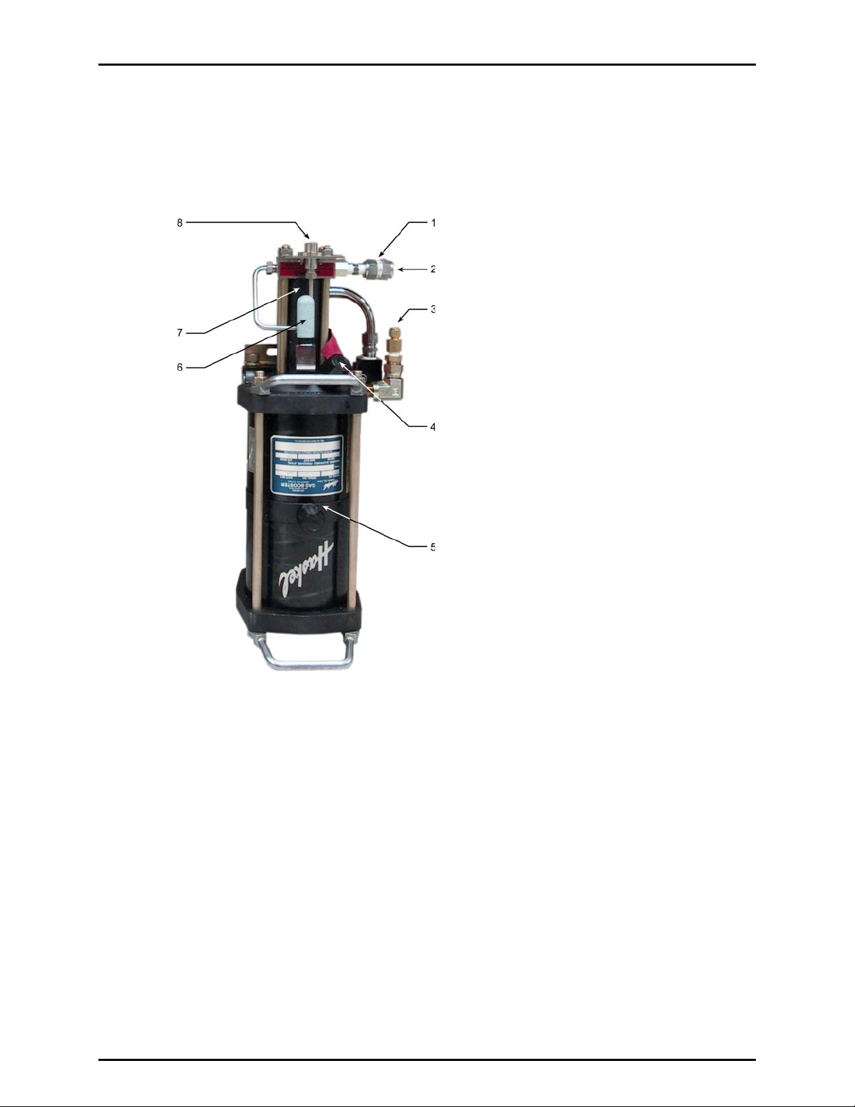
1.2 LOCATION AND DESCRIPTION OF THE COMPONENTS
1.2.1 GAS BOOSTER
1. High pressure instrument gas filter
2. High pressure instrument gas supply port
3. Drive air supply port (from Drive Air Control Kit)
4. Breather port
5. Low pressure piston body
6. Muffler
7. High pressure piston body
8. High pressure output port
Figure 1. GB-152-AF Gas Booster
© 2007 DH Instruments, a Fluke Company Page 2
Page 11

1. INTRODUCTION
1.2.2 DRIVE AIR CONTROL KIT
1. Drive air supply connection (not visible)
2. Drive pressure adjust regulator
3. Drive pressure indication gauge
4. Drive air shut off valve
5. Drive air out connection, to booster (not visible)
Figure 2. Drive air control kit
1. Drive pressure adjust regulator
2 Drive pressure indicator gauge
3. Drive air shutoff valve
4. High pressure instrument gas
supply port
Figure 3. System schematic
5. High pressure outlet port (to
GPC1-10000-AF SUPPLY port)
6. Booster pump
7. 1/4 in. PFA tubing
8. Drive air inlet port
Page 3 © 2007 DH Instruments, a Fluke Company
Page 12

GB-152-AF™ OPERATION AND MAINTENANCE MANUAL
1.3 SPECIFICATIONS
Dimensions:
GB-152 Booster: 584 mm H x 241 mm W x 241 mm D (23 in. x 9.5 in. x 9.5 in.)
Weight:
Pressure Supply
Pressure Range:
Supply Flow Rates:
Pressure
Connections:
Nominal Booster
Piston Ratio:
PGC-10000-AF SYSTEM
Temperature:
GB-152 Booster:
Drive Air Control Kit:
Shop Drive Air:
High Pressure Supply
Shop Drive Air:
High Pressure Supply
Drive Air Supply Inlet:
High Pressure Gas
Supply Inlet:
High Pressure Outlet:
GB-152 Booster: 152:1
16.4 kg (36 lbs)
1.8 kg (4 lbs)
75 psi (500 kPa)
Maximum high pressure output is drive air pressure
times 152
400 to 3 000 psi (3 to 20 MPa)
Maximum high pressure output is high pressure supply
Gas:
times 25
15 to 75
Gas:
scfm (425 to 2 125 slm)
5 to 20 scfm (140 to 560 slm)
1/4 in. NPT female
1/4 in. NPT female
DH 500 female (DH500 F is a gland and collar type fitting for
coned and left hand threaded 1/4 in. (6 mm) OD tube,
equivalent to AE F250C, HIP HF4, etc.)
Operating: 18 to 28 °C
Relative Humidity:
Storage: -20 to 70 °C
Operating: 15 to 70%RH (non-condensing)
Storage: 10 to 90%RH (non-condensing)
© 2007 DH Instruments, a Fluke Company Page 4
Page 13

2. INSTALLATION
.
22.
I
NNSSTTAALLLLAATTIIOON
I
N
2.1 UNPACKING AND INSPECTION
The GB-152-AF booster is delivered enclosed in plastic bag and secured by foam in place in a
corrugated box. The Drive Air Control Kit and Interconnections Kit are included in the same box.
Remove all parts from the shipping box and plastic bag. Be sure not to lose or discard the Drive Air
Control Kit and Interconnections Kit.
Inspect all parts for damage. If damage is noted, report it to your Receiving Department for appropriate
action.
A new GB-152-AF includes all items listed in Table 1.
Table 1. GB-152-AF Parts List
DESCRIPTION PART NO.
GB-152-AF Gas Booster 402163
ACCESSORIES
1 ea.
1 ea. Drive Air Control Kit 400998
INTERCONNECTIONS KIT:
2 m (6ft) 1/4 in. PFA tubing 101450-Z
1 ea. Union, DH500 100295
1 ea. Elbow, DH500 100168
1 ea. Nipple, 6 in. (152 mm), DH500 100208
1 ea. Nipple, 60 in. (1524 mm) x 1/8 in. (3 mm) with DH500 tips (coiled) 124199
PGC-10000-AF Documentation Disk including:
• RPM4/HPMS A70M/A20M-AF Operation and Maintenance
Manual, p/n 550136
• GPC1-10000-AF Operation and Maintenance Manual,
p/n 550135
• GB-152-AF Operation and Maintenance Manual, p/n 550137
402189
(Shipped with
RPM4/HPMS
accessories
in transport
case)
402162
Page 5 © 2007 DH Instruments, a Fluke Company
Page 14

GB-152-AF™ OPERATION AND MAINTENANCE MANUAL
2.2 PGC-10000-AF SYSTEM
GB-152-AF is usually delivered as the high pressure gas supply component of a PGC-10000-AF
Pneumatic Gauge Calibration System. The PGC-10000-AF system includes:
• RPM4/HPMS A70M/A20M-AF: Reference pressure monitor and high pressure mounting system used
as the pressure measuring reference of the calibration system.
• GPC1-10000-AF: Gas pressure controller used to set and adjust high pressure gas in the calibration
system.
• GB-152-AF: Gas booster package used to supply gas pressure up to 10 000 psi (70 MPa) to the
GPC1-10000-AF pressure controller.
Each of the three components of the PGC-10000-AF system has its own Operation and Maintenance
Manual and individual setup and start up instructions. Figure 4 shows the typical setup configuration of
the complete PGC-10000-AF system.
RPM4/HPMS A70M/A20M Reference Pressure Monitor
RPM4/HPMS A70M/A20M Reference Pressure Monitor
Remote ENTER
Remote ENTER
Footswitch
Footswitch
CAUTION
CAUTION
GB152-AF
GB152-AF
Drive Air Control Kit
Drive Air Control Kit
GB152-AF
GB152-AF
Gas Booster
Gas Booster
GPC1-10000-AF
GPC1-10000-AF
Gas Pressure Control ler
Gas Pressure Control ler
Drive air
Drive air
connection
connection
High pressure
High pressure
instrument gas
instrument gas
connection
connection
Figure 4. Typical PGC-10000-AF installation layout
© 2007 DH Instruments, a Fluke Company Page 6
Page 15

2. INSTALLATION
2.3 SITE REQUIREMENTS
2.3.1 SITE
There are no special site requirements.
The GB-152-AF gas booster system is divided into two parts: the Gas Booster itself and the
Drive Air Control Kit. The two parts are separated so that they may be installed separately.
The gas booster, which is large and relatively noisy, does not need to be accessed regularly.
It is generally mounted out of the way, for example under and behind a work bench.
The booster may be set horizontally or vertically.
Connections of gas supplies and output need to be considered carefully when selecting the
installation site.
See Sections 2.2 and 2.4 for additional recommendations.
2.3.2 GAS SUPPLIES
Two sources of gas pressure are required to operate the gas booster. They are drive air
(see Section 2.3.2.1) and high pressure instrument gas (see Section 2.3.2.2).
2.3.2.1 DRIVE AIR SUPPLY
The drive air supply provides power to operate the booster. The booster’s very
high pressure output is approximately the drive air pressure multiplied by 152.
This supply is usually “shop” or “factory” air.
Drive air requirements are:
Flow rate: 15 scfm (425 slm) minimum
Cleanliness: Not critical, use 60 micron filter
Humidity: 20 to 50 % RH. Do not use dry gas
Pressure: 75 psi (500 kPa)
Depending on the drive pressure set by the DRIVE ADJUST regulator,
GB-152-AF may generate pressure over 70 MPa (10 000 psi). To limit the maximum
pressure that can be generated by the booster, limit the drive air supply to the Drive
Air Control Kit to 75 psi (500 kPa) (see Section 2.3.2.1).
2.3.2.2 HIGH PRESSURE INSTRUMENT GAS
High pressure instrument gas is boosted by the booster and output from the
booster high pressure OUT port.
High pressure instrument gas supply requirements are:
Flow rate: 5 scfm (140 slm) minimum
Cleanliness: Use clean, dry instrument grade gases only.
Pressure: 400 to 3 000 psi (2 to 20 MPa)
Maximum boosted pressure output is high pressure supply
times 25.
Page 7 © 2007 DH Instruments, a Fluke Company
Page 16

GB-152-AF™ OPERATION AND MAINTENANCE MANUAL
2.4 INSTALLATION AND INITIAL SETUP
2.4.1 GENERAL CONSIDERATIONS
If the GB-151-AF is being installed as part of a PGC-10000-AF Pneumatic Gauge Calibration
System, see Section 2.2.
The GB-152-AF gas booster system is divided into two parts: the gas booster itself and the
Drive Air Control Kit. The two parts are separate so that they may be installed separately.
The gas booster, which is large and relatively noisy, does not need to be accessed regularly.
It is generally mounted out of the way, for example under and behind a work bench.
The booster may be set horizontally or vertically.
The Drive Air Control Kit allows local control of booster operation. The output pressure of the
booster can be set by adjusting the drive air pressure and the SHUTOFF valve turns the
booster ON and OFF. The Drive Air Control Kit is a bracket meant to be mounted at a
location convenient to the operator, for example on the front of a work bench.
When selecting the site for installation of the GB-152-AF gas booster system, carefully
consider access for the connections that need to be made (drive air to the Drive Air Control
Kit, high pressure instrument gas to the booster, very high pressure gas output from the
booster to the GPC1-10000-AF Gas Pressure Controller). Figure 4 presents a typical layout
of a complete PGC-10000-AF system, including the GB-152-AF gas booster system.
The orientation of the booster is of no consequence to its operation. It may be installed vertically,
horizontally or any combination of the two with no affect on performance or maintenance.
A variety of factors must be considered when determining where to locate the gas booster
and the Drive Air Control Kit. Factors include, but are not limited to:
• If control over booster operation (ON/OFF, setting output pressure) by the operator is
desired, locate the Drive Air Control Kit where it can be easily accessed.
• The high gas pressure being generated and associated safety concerns.
• The source of gas supplies (drive air supply and high pressure instrument gas supply).
• Point of use of output pressures.
• Noise levels. The booster operation is noisy.
• Vibration during use.
2.4.2 INSTALLATION
The installation of the gas booster system is broken down into four parts:
• Installation of the gas booster (see Section 2.4.2.1)
• Installation and connection of the Drive Air Control Kit (see Section 2.4.2.2)
• Connection of the booster high pressure instrument gas supply (see Section 2.4.2.3)
• Connection of the booster high pressure output (see Section 2.4.2.4)
© 2007 DH Instruments, a Fluke Company Page 8
Page 17

2. INSTALLATION
2.4.2.1 BOOSTER INSTALLATION
To install the gas booster system, follow the steps below:
Place the gas booster in the appropriate location (see Section 2.4.1).
Consider the booster high pressure instrument gas supply and high pressure
output connections. The booster may sit vertically or horizontally.
Orientation does not affect operation.
Use the mounting brackets attached to the booster to secure the booster to a
fixed location if desired.
Due to the reciprocating nature of the booster, it is advised that shock
mounts be used when rigidly mounting the booster.
2.4.2.2 DRIVE AIR CONTROL KIT INSTALLATION
To install the Drive Air Control Kit, follow the steps below:
Identify an appropriate location for the Drive Air Control Kit bracket (see Section
2.4.1). Consider the routing of the tubing to the Control kit from the drive air
supply and from the Control Kit bracket to the booster when selecting a location.
The kit bracket is often mounted on the front bottom surface of a work bench.
Figure 4 shows a typical installation configuration for a complete PGC-10000-AF
system.
Mount the Drive Air Control Kit bracket onto the desired location using the
bracket mounting holes provided.
Back off (rotate counterclockwise) the DRIVE ADJUST regulator and put the
SHUTOFF valve in the OFF position.
Connect the drive air supply to the 1/4 in. NPT F connection on the DRIVE
ADJUST regulator. Use tubing rated for at least 150 psi (1 MPa) working
pressure. See Section 2.3.2.1 for information on drive air supply
requirements.
Maximum input pressure to the DRIVE ADJUST regulator is 150 psi (1 MPa).
Pressures above this level may result in a failure that could damage the instrument
and/or cause personal injury.
Connect the Drive Air Supply Kit SHUTOFF valve output to the booster
DRIVE AIR INPUT port using the 6 ft (2 m) length of 1/4 in. PFA tubing
provided in the GB-152-AF accessories. Both fittings are 1/4 in. swage.
Page 9 © 2007 DH Instruments, a Fluke Company
Page 18

GB-152-AF™ OPERATION AND MAINTENANCE MANUAL
2.4.2.3 BOOSTER HIGH PRESSURE INSTRUMENT GAS SUPPLY
CONNECTION
Connect a high pressure gas supply to the gas booster high pressure IN port.
The IN port is a 1/4 in. NPT F fitting on the high pressure gas filter. Use a thread
sealer to seal the connection. The high pressure gas supply should not exceed
3 000 psi (200 MPa). See Section 2.3.2.2 for additional information on high
pressure gas supply requirements.
Pressure present at the High Pressure IN port will be present at the high
pressure OUT port. Do not supply pressure to the high pressure IN port unless you
are prepared for an equivalent pressure to be supplied to the high pressure OUT port.
2.4.2.4 BOOSTER HIGH PRESSURE OUTPUT CONNECTION
If the GB-152-AF is part of a PGC-10000-AF Pneumatic Gauge Calibration
System, the booster high pressure OUT port is connected to a GPC1-10000-AF
Gas Pressure Controller SUPPLY port (see the GPC1-10000-AF Operation and
Maintenance Manual). The GB-152-AF includes an interconnection kit with
fittings necessary to connect the high pressure OUT port to a GPC1.
To connect the GB-152-AF high pressure OUT port to the GCP1 SUPPLY port,
proceed as follows:
n Remove the orange plastic dummy plug from the DH500 fitting in the GB-152
OUT port. Retain the collar that is on the plug.
Remove the orange plastic dummy plug from the DH500 fitting in the
GPC1-10000-AF SUPPLY port.
Refer to Figure 5. Use the tubing and fittings supplied in the GB-152-AF
interconnections kit (see Table 1):
• Connect the DH500 2.75 in. (70 mm) nipple to the DH500 elbow.
• Connect the DH500 6 in. (152 mm) nipple to the DH500 union.
• Connect the union/6 in. nipple assembly to the open connection on the
elbow/2.75 in nipple assembly.
• Connect the 2.75 in. nipple end of the just completed assembly to the
GPC1 SUPPLY port.
• Connect the 60 in. (1524 mm) x 1/8 in. nipple with DH500 tips to the
open connection on the DH500 union of the assembly that is already
connected to the GPC1.
• Connect the other end of the 60 in. x 1/8 nipple to the high pressure OUT
port of the GB-152-AF.
Test that all fittings tightened before applying pressure.
© 2007 DH Instruments, a Fluke Company Page 10
Page 19

2. INSTALLATION
1. 60 in. x 1/8 in. nipple with DH500 tips
(to GB-152-AF high pressure OUT port)
2. DH500 union
3. 6 in. DH500 nipple
Figure 5. Connection of GB-152-AF high pressure OUT port to
GPC1-10000-AF SUPPLY port
4. DH500 elbow
5. 2.75 in. DH500 nipple
6. GPC1-10000-AF SUPPLY port
7. GPC1-10000-AF
Depending on the drive pressure set by the DRIVE ADJUST regulator,
GB-152-AF may generate pressure over 70 MPa (10 000 psi). To limit the maximum
pressure that can be generated by the booster, limit the drive air supply to the Drive
Air Control Kit to 75 psi (500 kPa) (see Section 2.3.2.1). Be sure to connect the
booster high pressure output using fittings and tubing rated for the maximum
expected pressure that is to be output from the booster. Always use a DH500 or
equivalent tube on the DH500 F high pressure OUT port connection.
Page 11 © 2007 DH Instruments, a Fluke Company
Page 20

GB-152-AF™ OPERATION AND MAINTENANCE MANUAL
2.5 INITIAL START UP
After installing the gas booster (see Section 2.4.2), perform the initial start up as follows:
Supply drive air: Check that the Drive Air Control Kit SHUTOFF valve is in the OFF position and that
the DRIVE ADJUST regulator is set to zero (fully counterclockwise). Apply drive pressure to the
SHUTOFF valve (see Section 2.3.2.1 for information on drive air supply requirements).
Depending on the drive pressure set by the DRIVE ADJUST regulator, GB-152-AF may generate pressure
over 70 MPa (10 000 psi). To limit the maximum pressure that can be generated by the booster, limit the drive
air supply to the Drive Air Control Kit to 75 psi (500 kPa) (see Section 2.3.2.1).
Supply high pressure instrument gas: Check that all connections to the high pressure IN and OUT
ports are secure. Apply high pressure gas to the high pressure IN port (see Section 2.3.2.2 for
information on high pressure instrument gas).
Ensure the high pressure supply does not exceed 3 000 psi (20 MPa). Pressure above this may result in
a failure that could damage the instrument and/or cause personal injury.
Adjust the DRIVE ADJUST regulator: Rotate the DRIVE ADJUST regulator knob (clockwise)
while observing the set pressure on the DRIVE gauge. Set the drive pressure to the maximum
desired high pressure output divided by the booster ratio (152 for GB-152-AF). Do not set the
regulator to more than 65 psi (450 kPa). Remember that when the SHUTOFF valve is in the ON
position, the booster will operate until the high pressure output is equal to the drive air setting times
the booster ratio.
The DRIVE ADJUST regulator is NOT self venting so it cannot be used to set pressure lower than the
current pressure when the SHUTOFF valve is OFF. If you overshoot the desired set point, set the SHUTOFF
valve to ON until the DRIVE pressure is lower than your desired setting. Then set the SHUTOFF valve to OFF
and use the regulator to adjust the pressure in the ascending direction.
Generate high pressure: Check that the booster high pressure output is properly connected. If it is
connected to a GPC1-10000-AF, be sure the GPC1’s INLET valve is closed. Set the SHUTOFF valve to
the ON position. The booster will begin to cycle and will continue to cycle until it stalls. When it stalls, the
high pressure output is roughly equal to the drive pressure setting times the booster's ratio (152:1).
© 2007 DH Instruments, a Fluke Company Page 12
Page 21

3. OPERATION
.
33.
O
PPEERRAATTIIOON
O
N
3.1 GENERAL OPERATING PRINCIPLE AND INFORMATION
The purpose of the GB-152-AF booster is to automatically boost gas pressure to very high pressure. The
value of very high pressure that is generated depends on the drive air pressure setting. The unit generates
high pressure using a Pneumatically Operated Gas Booster Pump and a Drive Air Control Kit.
GAS BOOSTER PUMP
The booster pump is a Pascal press utilizing two pistons connected together on the same axis having a
normal area ratio of 152:1. The booster is a two-stroke, single stage reciprocating pump that generates
gas pressure 152 times greater than the shop drive air applied to the pump. The pump operates
automatically, provided drive air is supplied to the DRIVE ADJUST regulator and the regulator is set to at
least 140 kPa (20 psig). Operation is continuous until the outlet pressure is 152 times the shop drive air
pressure. Then, the opposing forces within the pump are in equilibrium and the pump stalls.
For example, using a GB-152-AF with the drive air pressure set to 45 psi (300 kPa), the pump will run
until the high pressure output reaches approximately 152 x 45 = 6840 psi.
The drive air (low pressure) section of the booster consists of a piston, cylinder, air cycling valve, pilot
valve and vent section. This section provides the reciprocating action and compression force needed to
operate the booster and generate the high pressure gas. Drive air is channeled to the appropriate side of
the piston (compression or suction stroke) by the air cycling valve. When the piston reaches full stroke, a
pilot valve is mechanically activated causing the air cycling valve to change position. Shop drive air is
routed to the opposite side of the piston reversing piston direction where a second pilot valve is activated
repeating the process.
The high pressure section of the booster consists of a small piston and an inlet/outlet check valve
assembly. The small piston moves forward and backward with the air drive piston. During the suction
stroke (backward movement), the outlet check valve closes and the inlet check valve opens letting supply
high pressure gas enter the compression chamber. During the compression stroke, the inlet check valve
closes and the outlet check valve opens letting boosted gas out of the pump.
The compression ratio of the high pressure piston is 25:1 (for both models). Maximum output pressure is
limited by the instrument gas supply pressure. For example, with 300 psi applied, maximum output
pressure cannot exceed 300 x 25 = 7 500 psi.
Page 13 © 2007 DH Instruments, a Fluke Company
Page 22

GB-152-AF™ OPERATION AND MAINTENANCE MANUAL
3.2 OPERATION
Once the gas booster has been set up and the initial start up is completed, operation is very simple.
There are two possible operator actions:
• Setting the booster output pressure (see Section 3.2.1).
• Turning the booster ON and OFF (see Section 3.2.2).
3.2.1 SETTING THE BOOSTER OUTPUT PRESSURE
Depending on the drive pressure set by the DRIVE ADJUST regulator, GB-152-AF may
generate pressure over 70 MPa (10 000 psi). To limit the maximum pressure that can be
generated by the booster, limit the drive air supply to the Drive Air Control Kit to 75 psi (500 kPa)
(see Section 2.3.2.1).
The booster output pressure is determined by the value of the drive air pressure. The
approximate booster output will be the drive air pressure times 152.
To set the drive air pressure, adjust the DRIVE ADJUST regulator:
With the SHUTOFF valve in the ON position, adjust the regulator counterclockwise while
observing the DRIVE gauge to decrease pressure to a value lower than the desired set
pressure. This is necessary because the regulator is not self-venting.
Put the SHUTOFF valve in the OFF position.
Rotate the DRIVE ADJUST regulator knob clockwise while observing the set pressure on
the DRIVE gauge. Set the drive pressure to the maximum desired high pressure output
divided by the booster ratio (152:1). For example, if the desired high pressure output of
the GB-152-AF is 10 000 psi, set the drive air pressure to 10000/152 = 66 psi.
Remember that when the SHUTOFF valve is in the ON position, the booster will operate
until the high pressure output is equal to the drive air setting times the booster ratio.
To correctly set the pressure, gas flow must not occur. If flow is present in the circuit when
the regulator is adjusted, the pressure will increase when flow is reduced. If the setpoint is
exceeded, see Section 3.2.2.
The booster will run automatically, continuously until the high pressure output is equal to
the drive pressure times 152. Set the drive pressure very carefully to avoid generating higher
output pressures than desired which could be dangerous. Do not apply more than 10 000 psi (70
MPa) to the GPC1-10000-AF SUPPLY port.
© 2007 DH Instruments, a Fluke Company Page 14
Page 23

3. OPERATION
3.2.2 TURNING THE BOOSTER ON AND OFF
The booster is turned ON and OFF using the SHUTOFF valve of the Drive Air Control Kit.
The SHUTOFF valve controls the supply of drive pressure to the booster.
Set the SHUTOFF valve to the ON position to supply drive pressure to the booster and cause
it to operate.
Set the SHUTOFF valve to the OFF position to interrupt drive pressure to the booster and
stop its operation.
When the booster is OFF, the high pressure supply is still present at the high pressure gas
OUT port. This feature makes it easy to operate using the high pressure supply only when the
booster is not needed.
Emergency shut-down of the gas booster pump can be performed at any time by closing the
Drive Air Control Kit SHUTOFF Valve. This will prevent further generation of gas pressure by the
pump but WILL NOT NECESSARILY reduce pressure to high pressure point-of-use.
Page 15 © 2007 DH Instruments, a Fluke Company
Page 24

GB-152-AF™ OPERATION AND MAINTENANCE MANUAL
N
N
OOTTE
E
© 2007 DH Instruments, a Fluke Company Page 16
Page 25

4. MAINTENANCE
44..
M
AAIINNTTEENNAANNCCEE
M
AANNDD
A
DDJJUUSSTTMMEENNTTS
A
S
4.1 MAINTENANCE
GB-152-AF gas booster packages require no routine maintenance or adjustments.
4.2 ILLUSTRATED PARTS BREAKDOWN
Table 2. GB-152-AF Assembly Illustrated Parts Breakdown
# REQUIRED
1 Gas Booster AG152
1 High pressure gas filter 4205T-2PP
1 Nipple, 1/4 inch 4NP-316
1 Reducer 28-223
1 Adaptor 4CF4
1 Boss 6-1/4F50G
1 DH500 bulkhead 123812-01
3 DH500 gland 60-2HM4-316
3 DH500 collar 60-2H4-316
1 Tube, SS 20-9M4-316
1 Mounting plate 123492
1 Drive air control panel 123571
1 Regulator 44-2213-242-009
1 Pressure gauge 25.120, 300PSI
1 Shutoff valve B-42S4
1 Adaptor, straight 101477
1 Adaptor, Elbow 2LM4
1 Adaptor, Elbow 4SLP
1 Plug 28-094
1 Tube, SS, 1/8 inch OD 304-F1-125X028-S
1 Tube, PFA, 1/4 inch OD 0317-037
1 Adaptor 2CF4-BR
DESCRIPTION
PART NO.
Page 17 © 2007 DH Instruments, a Fluke Company
Page 26

GB-152-AF™ OPERATION AND MAINTENANCE MANUAL
© 2007 DH Instruments, a Fluke Company Page 18
Page 27

5. 8BTROUBLESHOOTING
.
55.
T
RROOUUBBLLEESSHHOOOOTTIINNG
T
G
5.1 GENERAL INFORMATION
Before using this trouble shooting section, the operator should be thoroughly familiar with the AG-152-
AF gas booster system.
For problems not covered in this section or direct technical assistance, please contact a DHI Authorized
Service Provider (see Section 6, Table 2).
5.2 BOOSTER WILL NOT RUN
The booster is a pneumatically operated pump. The reciprocating action is caused by an imbalance of forces
within the pump due to the opposing drive air pressure and the high pressure gas supply that is being
boosted. If the booster is not operating, it means that all forces are equal or that the pistons are seized.
• Check that the Drive Air Control Kit SHUTOFF valve is in the ON position. If not, set the valve fully to
the ON position.
• Check that drive air pressure supply is actually present at the DRIVE ADJUST regulator inlet
connection. If not, ensure drive air is supplied at the proper pressure and flow value (see Section
2.3.2.1).
• Check that the DRIVE ADJUST regulator is set to a pressure of 20 psig (150 kPa) or higher and that
minimum flow requirements are met (see Section 2.3.2.2).
• Check that there are no gas leaks in the drive air circuit supplying the DRIVE ADJUST regulator.
Repair any existing leaks.
• Check that gas is not continuously venting from the exhaust muffler. If gas is venting through the
muffler, see Section 5.8.
• Check that the booster is not in a stalled state. If the booster is stalled, determine the reason and
remedy. A stalled state occurs when the pressure in the high pressure section of the booster is equal
to the pressure in the low pressure section times the ratio (152). A stall can only occur if the high
pressure circuit is plugged.
Page 19 © 2007 DH Instruments, a Fluke Company
Page 28

GB-152-AF™ OPERATION AND MAINTENANCE MANUAL
5.3 BOOSTER RUNS TOO SLOWLY
A slow running booster means that the pump itself is running slowly which also causes the pressure to be
generated slowly.
• Check that the drive air SHUTOFF valve is in the ON position. If not, set the valve fully to the
ON position.
• Check that the DRIVE ADJUST regulator is set to a pressure of 20 psig (150 kPa) or higher and that
minimum flow requirements are met (see Section 2.3.2.2).
• Check that there are no restrictions in the shop drive air supply circuit that would prevent adequate
air flow (see section 2.3.2.1). Remove any restrictions. If a filter is installed on the shop drive air
circuit, it may cause an excessive flow restriction.
• Check that there are no leaks in the shop drive air circuit. Repair any existing leaks.
5.4 PRESSURE GENERATES TOO SLOWLY OR NOT AT ALL
A slow running booster will cause the pressure to be generated slowly. Ensure that the booster is
running properly (see Section 5.3). Then follow the sequential steps below:
• Check that the high pressure gas supply is not below 300 psi (2 MPa). If the supply is too low,
increase supply pressure. Speed of booster pressure generation is directly related to the pressure of
the high pressure instrument gas supply. For example, pressure will be generated twice as fast with
instrument gas supply of 2 000 psi (14 MPa) than with 1 000 psi (7 MPa).
• Check that there are no restrictions in the high pressure gas supply line to the booster. If a restriction
exists, remove it. Restriction may be a valve not fully opened, a regulator with a low flow constant
(CV), an inline filter, small diameter tubing, etc.
• Check that there are no leaks in the high pressure line from the booster OUT port to the point-of-use.
Repair any leaks.
• Check that the inlet and outlet check valves in the high pressure booster piston are
operating properly. Make sure the high pressure gas supply to the booster IN port is 300 psi (2 MPa)
or greater and the drive air is set to at least 60 psi (400 kPa). Close the drive air SHUTOFF valve.
Shutoff the high pressure OUT port near the port or, better yet, plug the port directly with a DH500
plug.
Open the drive air SHUTOFF valve. The booster should cycle several times then stall. If the booster
does not stall, a failure of the booster check valves is the most likely cause. In this case, the booster
needs service. Contact a DHI Authorized Service Provider.
© 2007 DH Instruments, a Fluke Company Page 20
Page 29

5. 8BTROUBLESHOOTING
5.5 BOOSTER RUNS (CYCLES) CONTINUOUSLY
The booster is a pneumatically operated pump. The reciprocating action is caused by an imbalance of
forces within the pump due to the opposing drive air pressure and the high pressure instrument gas
supply that is being boosted. If the booster runs continuously, and there is no problem with the check
valves (see Section 5.4), it means that the forces do not equalize.
• Check that the high pressure supply to the booster IN port is at least 300 psi (2 MPa). If not, ensure
that supply meets required specifications (see Section 2.3.2.2).
• Check that the high pressure circuit connected to the booster OUT port is not open to atmosphere or
doesn’t have a severe leak.
• If the shop drive air supply pressure is above 40 psig (250 kPa), adjust to below this limit. If the
booster stops running, increase high pressure supply to IN port instrument gas supply and try again.
5.6 CANNOT ACHIEVE DESIRED PRESSURE
• Check that the high pressure gas supply to the booster IN port is set above 300 psi (2 MPa)
(the minimum value). In some cases, the minimum pressure supply is 600 psi (40 MPa). If in doubt,
increase instrument gas supply to 600 psi (40 MPa).
• Check that the drive air is set at the correct value and that it is supplied to the booster. See Section
2.3.2.1.
• Check that no leaks exist in any of the pressure circuits. Repair any existing leaks.
Page 21 © 2007 DH Instruments, a Fluke Company
Page 30

GB-152-AF™ OPERATION AND MAINTENANCE MANUAL
5.7 LEAKS
Pressure leaks are the most common problem found in pressure handling equipment. Normally, the first
step is to determine if the leak is within the booster or outside of the unit.
• To determine if the leak is within the unit, disconnect at the booster high pressure OUT port and
plug it. Establish similar conditions under which the leak was observed and determine if the leak is
still present. For small leaks, it may be necessary to install an appropriate pressure sensing device
at the OUT port. In some cases, it is useful to perform simple leak checks on the most common
outside sources before disconnecting the test system. Note that leaks inside the booster are unusual
unless there has been some disassembly.
• More than one leak can exist in a system. Fixing one leak does not guarantee a leak tight system.
Therefore, continue executing the troubleshooting procedures until all leaks are located
and corrected. Since it is impractical to produce a troubleshooting guide that will cover every
conceivable leak, the source of your leak may not be covered in this guide.
• Check all fittings and components for leaks. Use leak detection fluid for small leaks. Tighten loose
fittings or replace damaged fittings. Repair or replace leaking regulators.
Never tighten a fitting while it is under pressure. If pressure is in the system and the fitting should fail
while being tightened, you or those around you may be injured.
Do not over-torque the DH500 fittings that are inside the booster. To do so will damage them,
requiring their replacement. Recommended torque on a DH500 fitting gland is 15 Nm.
It is possible that a leak exists in the high pressure section of the gas booster. These leaks are very difficult to
isolate and detect. If no leaks can be found following the above procedures, it is likely the problem is within
the booster. Contact a DHI Authorized Service Provider for assistance (Section 6, Table 2).
5.8 GAS CONTINUOUSLY VENTS THROUGH
EXHAUST MUFFLER
When the booster does not run and gas is venting through the muffler, the boosters air cycling valve
(spool valve) is stuck between its toggle points. This is normally caused by a low gas flow rate.
There are two methods for restoring proper operation. It is recommended to perform them in the
order below:
• Put the drive air SHUTOFF valve in the OFF position. Plug the booster high pressure OUT port.
Increase drive air pressure, using the DRIVE ADJUST regulator, to 65 (450 kPa). Put the drive air
SHUTOFF valve into the ON position quickly. If the booster begins to operate normally, set the drive
air SHUTOFF valve to OFF and reset the regulator to previous settings. Repeat the process until the
booster begins normal operation.
• Put the drive air SHUTOFF valve in the OFF position. Plug the booster high pressure OUT port.
Increase drive air pressure using the DRIVE ADJUST regulator to 65 (450 kPa). Remove the
exhaust muffler and use your hand to plug the vent port. Put the drive air SHUTOFF valve into the
ON position quickly. When the build-up of pressure begins to leak past your hand, quickly
remove it. If the booster begins to operate normally, set the drive air SHUTOFF valve to OFF,
reinstall the muffler and reset regulators to previous settings. Repeat the process until the booster
begins normal operation.
If normal operation cannot be restored, contact a DHI Authorized Service Provider.
© 2007 DH Instruments, a Fluke Company Page 22
Page 31

6. 9BWARRANTY STATEMENT
.
66.
W
AARRRRAANNTTYY
W
S
TTAATTEEMMEENNT
S
T
6.1 WARRANTY STATEMENT
Except to the extent limited or otherwise provided herein, DH Instruments (DHI) warrants for one year
from purchase, each new product sold by it or one of its authorized distributors, only against defects in
workmanship and/or materials under normal service and use. Products which have been changed or
altered in any manner from their original design, or which are improperly or defectively installed, serviced
or used are not covered by this warranty.
DHI and any of its Authorized Service Providers’ obligations with respect to this warranty are limited to
the repair or replacement of defective products after their inspection and verification of such defects.
All products to be considered for repair or replacement are to be returned to DHI, or its Authorized
Service Provider, freight prepaid, after receiving authorization from DHI or its Authorized
Service Provider.
The buyer assumes all liability vis-à-vis third parties with respect to its acts or omissions involving use of
the products. In no event shall DHI be liable to purchaser for any unforeseeable or indirect damage,
it being expressly stated that, for the purpose of this warranty, such indirect damage includes, but is not
limited to, loss of production, profits, revenue, or goodwill, even if DHI has been advised of
the possibility thereof, and regardless of whether such products are used individually or as components
in other products.
Items returned to DHI under warranty claim but determined to not have a defect covered under warranty
or to not have a defect at all are subject to an evaluation and shipping charge as well as applicable repair
and/or calibration costs.
The provisions of this warranty and limitation may not be modified in any respect except in writing signed
by a duly authorized officer of DHI.
The above warranty and the obligations and liability of DHI and its Authorized Service Providers exclude
any other warranties or liabilities of any kind.
Table 3. DHI Authorized Service Providers
DH INSTRUMENTS, A FLUKE COMPANY
AUTHORIZED SERVICE PROVIDERS
COMPANY
DH Instruments, a Fluke
Company
Minerva Meettechniek B.V. Chrysantstraat 1
Ohte Giken, Inc.
Technology Center
4765 East Beautiful Lane
Phoenix AZ 85044-5318
USA
3812 WX Amersfoort
the NETHERLANDS
258-1, Nakadai
Kasumigaura-machi,
Niihari-Gun,
Ibaraki 300-0133
ADDRESS
TELEPHONE,
FAX & EMAIL
Tel 602.431.9100
Fax 602.431.9559
cal.repair@dhinstruments.com
Tel (+31) 33.46.22.000
Fax (+31) 33.46.22.218
info@minervaipm.com
Tel 81/29.840.9111
Fax 81/29.840.9100
tech@ohtegiken.co.jp
NORMAL SUPPORT
REGION
Worldwide
European Union
Japan/Asia
Page 23 © 2007 DH Instruments, a Fluke Company
 Loading...